Embed Size (px)
Citation preview

Microelectronic Engineering 88 (2011) 3087–3093
Contents lists available at ScienceDirect
Microelectronic Engineering
journal homepage: www.elsevier .com/locate /mee
Photosensitive sacrificial polymer with low residue
Yu-Chun Chen, Paul A. Kohl ⇑School of Chemical and Biomolecular Engineering, Georgia Institute of Technology, Atlanta, GA 30332-0100, United States
a r t i c l e i n f o a b s t r a c t
Article history:Received 21 February 2011Received in revised form 28 May 2011Accepted 31 May 2011Available online 25 June 2011
Keywords:Sacrifical polymerPolypropylene carbonate
0167-9317/$ - see front matter � 2011 Elsevier B.V. Adoi:10.1016/j.mee.2011.05.034
⇑ Corresponding author.E-mail address: [email protected] (P.A. Kohl).
In this study, a technique is described to achieve enclosed air-cavities using a photosensitive sacrificialpolymer with significantly lower residue. The residual residue after decomposition of the sacrificial poly-mer originates primarily from the photoacid generator used for patterning the polymer. In the two-layertechnique, the photoacid is added only to the top layer resulting in significantly lower overall PAG load-ing. During decomposition, the photoacid used to decompose the polymer in the top layer then diffusesinto the acid-free region promoting decomposition in the otherwise non-photosensitive layer. Thisapproach significantly lowered the amount of residue produced. These results also showed that the acidgenerated from the PAG after UV radiation was not consumed by the polymer in the layer from which itoriginated. Rather, the acid was reused in other layers. The patterns fabricated from the two-layer struc-ture used less PAG, had higher spatial resolution, and less line edge roughness. When the thickness of thetop PAG-loaded layer was decreased, a lower UV exposure dose was required to achieve patterning.
� 2011 Elsevier B.V. All rights reserved.
1. Introduction
The decomposition of a sacrificial polymer in an enclosed spaceoffers a simple method to create air cavities for electronic, mechan-ical, or release layer functions [1]. Air cavities created after thedecomposition of a sacrificial polymer have a wide variety of wa-fer-level applications, including formation of micro- and nano-scale air channels [2–4], microelectromechanical system (MEMS)packaging [5], and as a low-K dielectric for microelectronic devices[6]. Previously used sacrificial polymers include polynorbornene[3], polycaprolactone [7], and polycarbonate [4,8,9]. The optimummethod for patterning the sacrificial polymer depends on the de-sired feature size, spatial resolution, polymer thickness, purity(residue) requirements, and cost. The sacrificial polymer can bemade photosensitive by the addition of a photo-active compound[3,10,11]. Sacrificial polymers such as poly(propylene carbonate)(PPC) can also be patterned via reactive ion etching.
Pure PPC decomposes by chain scission and unzipping creatinggaseous products including carbon dioxide and acetone [12–16].The decomposition of PPC can be catalyzed by the addition of astrong acid resulting in lowering the decomposition temperature[16]. The change in the decomposition temperature can bephoto-initiated by the addition of a photo acid generator (PAG)[11,17]. Upon irradiation of the PAG with ultraviolet (UV) radiationproduces an acid which causes the decomposition temperature todecrease [8,11,18], thus making the polymer photo-sensitive forpatterning [1,5,7,11,19,20]. A previous study has described the
ll rights reserved.
decomposition mechanism for diphenyliodonium (DPI) cationand conjugate base of a strong acid, as shown in Fig. 1 [11]. The cat-ion dissociates into two radicals after UV photo-excitation andheating. Both radical species are stabilized by the benzyl groups.A proton is generated which together with the conjugate baseforms a strong acid after reacting with the residual solvent or poly-mer [11].
Some acids have a significantly high vapor pressure at the pro-cessing temperatures leading to evaporation of the generated acidfrom the polymer matrix. Acids with low vapor pressure lead to ahigh concentration of the acid in the polycarbonate as the filmdecomposes. These nonvolatile PAG salts precipitate when thepolycarbonate decomposes into a gas and leaves. The residue pro-duced can be seen after decomposition of the PPC [11]. While theaddition of a PAG to PPC makes the sacrificial polymer photosensi-tive, a highly valuable attribute, it nevertheless results in the addi-tion of a low volatility component to the PPC mixture.
It has been found that greater than 3 wt.% PAG [11] is requiredin the PPC in order to achieve full photo-patterning capability. Anencapsulated air channel can be created by first photo-patterningthe PPC followed by overcoating with a dielectric material. ThePPC serves as a temporary space holder during deposition of theovercoat material. The sequence involves first spin-coating thephoto-sensitive PPC on a substrate, soft-baking, and UV-exposingthe PPC through a photo-mask. The acid created within the ex-posed PPC decomposes at a lower temperature than the unexposedarea, and the PPC converts into a gas leaving the unexposed PPC.The overcoat material on the patterned PPC provides mechanicalsupport to the air-cavity. The PPC space holder within the dielectricsuperstructure decomposes at a higher temperature, usually while
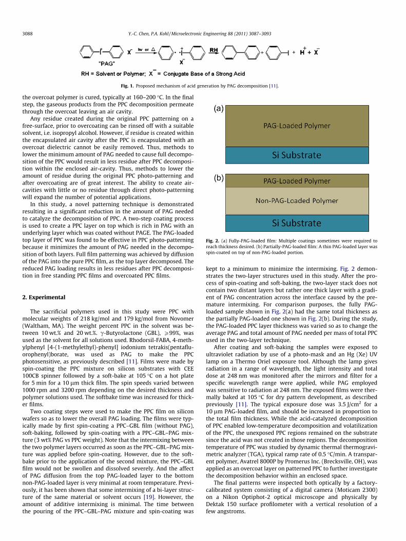
Fig. 1. Proposed mechanism of acid generation by PAG decomposition [11].
Fig. 2. (a) Fully-PAG-loaded film: Multiple coatings sometimes were required toreach thickness desired. (b) Partially-PAG-loaded film: A thin PAG-loaded layer wasspin-coated on top of non-PAG-loaded portion.
3088 Y.-C. Chen, P.A. Kohl / Microelectronic Engineering 88 (2011) 3087–3093
the overcoat polymer is cured, typically at 160–200 �C. In the finalstep, the gaseous products from the PPC decomposition permeatethrough the overcoat leaving an air cavity.
Any residue created during the original PPC patterning on afree-surface, prior to overcoating can be rinsed off with a suitablesolvent, i.e. isopropyl alcohol. However, if residue is created withinthe encapsulated air cavity after the PPC is encapsulated with anovercoat dielectric cannot be easily removed. Thus, methods tolower the minimum amount of PAG needed to cause full decompo-sition of the PPC would result in less residue after PPC decomposi-tion within the enclosed air-cavity. Thus, methods to lower theamount of residue during the original PPC photo-patterning andafter overcoating are of great interest. The ability to create air-cavities with little or no residue through direct photo-patterningwill expand the number of potential applications.
In this study, a novel patterning technique is demonstratedresulting in a significant reduction in the amount of PAG neededto catalyze the decomposition of PPC. A two-step coating processis used to create a PPC layer on top which is rich in PAG with anunderlying layer which was coated without PAGE. The PAG-loadedtop layer of PPC was found to be effective in PPC photo-patterningbecause it minimizes the amount of PAG needed in the decompo-sition of both layers. Full film patterning was achieved by diffusionof the PAG into the pure PPC film, as the top layer decomposed. Thereduced PAG loading results in less residues after PPC decomposi-tion in free standing PPC films and overcoated PPC films.
2. Experimental
The sacrificial polymers used in this study were PPC withmolecular weights of 218 kg/mol and 179 kg/mol from Novomer(Waltham, MA). The weight percent PPC in the solvent was be-tween 10 wt.% and 20 wt.%. c-Butyrolactone (GBL), P99%, wasused as the solvent for all solutions used. Rhodorsil-FABA, 4-meth-ylphenyl [4-(1-methylethyl)-phenyl] iodonium tetrakis(pentaflu-orophenyl)borate, was used as PAG to make the PPCphotosensitive, as previously described [11]. Films were made byspin-coating the PPC mixture on silicon substrates with CEE100CB spinner followed by a soft-bake at 105 �C on a hot platefor 5 min for a 10 lm thick film. The spin speeds varied between1000 rpm and 3200 rpm depending on the desired thickness andpolymer solutions used. The softbake time was increased for thick-er films.
Two coating steps were used to make the PPC film on siliconwafers so as to lower the overall PAG loading. The films were typ-ically made by first spin-coating a PPC–GBL film (without PAG),soft-baking, followed by spin-coating with a PPC–GBL–PAG mix-ture (3 wt% PAG vs PPC weight). Note that the intermixing betweenthe two polymer layers occurred as soon as the PPC–GBL–PAG mix-ture was applied before spin-coating. However, due to the soft-bake prior to the application of the second mixture, the PPC–GBLfilm would not be swollen and dissolved severely. And the affectof PAG diffusion from the top PAG-loaded layer to the bottomnon-PAG-loaded layer is very minimal at room temperature. Previ-ously, it has been shown that some intermixing of a bi-layer struc-ture of the same material or solvent occurs [19]. However, theamount of additive intermixing is minimal. The time betweenthe pouring of the PPC–GBL–PAG mixture and spin-coating was
kept to a minimum to minimize the intermixing. Fig. 2 demon-strates the two-layer structures used in this study. After the pro-cess of spin-coating and soft-baking, the two-layer stack does notcontain two distant layers but rather one thick layer with a gradi-ent of PAG concentration across the interface caused by the pre-mature intermixing. For comparison purposes, the fully PAG-loaded sample shown in Fig. 2(a) had the same total thickness asthe partially PAG-loaded one shown in Fig. 2(b). During the study,the PAG-loaded PPC layer thickness was varied so as to change theaverage PAG and total amount of PAG needed per mass of total PPCused in the two-layer technique.
After coating and soft-baking the samples were exposed toultraviolet radiation by use of a photo-mask and an Hg (Xe) UVlamp on a Thermo Oriel exposure tool. Although the lamp givesradiation in a range of wavelength, the light intensity and totaldose at 248 nm was monitored after the mirrors and filter for aspecific wavelength range were applied, while PAG employedwas sensitive to radiation at 248 nm. The exposed films were ther-mally baked at 105 �C for dry pattern development, as describedpreviously [11]. The typical exposure dose was 3.5 J/cm2 for a10 lm PAG-loaded film, and should be increased in proportion tothe total film thickness. While the acid-catalyzed decompositionof PPC enabled low-temperature decomposition and volatilizationof the PPC, the unexposed PPC regions remained on the substratesince the acid was not created in those regions. The decompositiontemperature of PPC was studied by dynamic thermal thermogravi-metric analyzer (TGA), typical ramp rate of 0.5 �C/min. A transpar-ent polymer, Avatrel 8000P by Promerus Inc. (Brecksville, OH), wasapplied as an overcoat layer on patterned PPC to further investigatethe decomposition behavior within an enclosed space.
The final patterns were inspected both optically by a factory-calibrated system consisting of a digital camera (Moticam 2300)on a Nikon Optiphot-2 optical microscope and physically byDektak 150 surface profilometer with a vertical resolution of afew angstroms.

Y.-C. Chen, P.A. Kohl / Microelectronic Engineering 88 (2011) 3087–3093 3089
3. Results and discussion
The decomposition temperature of PPC can be changed by theaddition of a photo acid catalyst (3 wt% PAG) followed by exposureto UV radiation, as shown by the TGA in Fig. 3. The PPC sample ex-posed to UV radiation had a decomposition temperature of ca.80 �C (50% decomposition temperature) while the unexposed sam-ple had a decomposition temperature of ca. 170 �C.
Fig. 3. Dynamic TGA plots of PAG-loaded PPC with and without UV exposure.
Fig. 4. Optical images of the photo-patterned structures: (a) Structure made of fullyPAG-loaded PPC and (b) structure made of partially PAG-loaded PPC.
The spatial resolution of the photosensitive, PAG-loaded PPC isshown in Fig. 4. The fully PAG-loaded polymer film was made byspin-coating a PPC–PAG mixture in solvent onto a silicon waferwith the final thickness of 32.2 lm. The partially PAG-loaded sam-ple with a total thickness of 32.7 lm was prepared by first spin-coating the silicon wafer with a PAG-free PPC layer to a thicknessof 26.4 lm followed by spin-coating a 6.3 lm thick layer of PAG-loaded PPC. This corresponds to an overall PAG loading of only20% of the normal PAG loading for the single layer PAG-loadedsample of the same thickness. Although the first layer spin-coatedonto the silicon wafer was PAG-free, there is a limited amount ofinteraction for the solvent, polymer, and PAG between the firstand second layers, as discussed previously in coating multi-layerpolymer films [21]. Both samples were exposed to UV radiationthrough a light-field lithographic mask that was encoded with ser-pentine patterns. The two wafers were baked on a hotplate at110 �C to decompose the exposed PPC patterns. The decompositiontime for the fully PAG-loaded film (3 wt% PAG) of such thicknesswas typically 4 min, and the decomposition time for the partiallyPAG-loaded film was typically about 13 min. The square, serpen-tine patterns on the mask were 600 lm wide. The spatial dimen-sions of the fully-PAG loaded PPC film, Fig. 4(a), were smallerthan the dimensions on the mask and showed considerable distor-tion and high line edge roughness. The partially PAG loaded, two-layer film, Fig. 4(b), had much tighter line width control andshowed much smoother line edge roughness.
It is clear from Fig. 4 that the line width control of the fully PAGloaded PPC film, Fig. 4(a), was severely degraded compared to thepartially PAG loaded film, Fig. 4(b). The pattern in Fig. 4(b) using
Fig. 5. Closer top view of the photo-patterned structures: (a) Fully PAG-loaded PPCand (b) partially PAG-loaded PPC. Please note the measurements of line width weredone at the bottom edges of the structures.

Fig. 6. Residue patterns after PPC decomposition: (a) Fully PAG-loaded PPC and (b)partially PAG-loaded PPC.
Fig. 7. Optical images taken after the overcoat was cured and PPC was decomposedsimultaneously: (a) Fully PAG-loaded PPC and (b) partially PAG-loaded PPC.
3090 Y.-C. Chen, P.A. Kohl / Microelectronic Engineering 88 (2011) 3087–3093
partially-PAG-loaded PPC used about 20% of PAG used in the fullyPAG loaded sample in Fig. 4(a). The excess PAG in fully loaded PPC,Fig. 4(a), distorts the unexposed PPC film causing decomposition ofthe PPC in the geometric shadow. Higher magnification images ofthe two samples in Fig. 4 are shown in Fig. 5. When the line widthon the photo mask was 600 lm, the line width of the fully PAG-loaded sample was only 446 lm due to the lateral diffusion ofthe photo-acid into the geometric shadow. The line width frompartially PAG-loaded was 621 lm, much closer to the mask dimen-sions. The lower total PAG content in the two-layer structure less-ened the diffusion of the activated PAG into the unexposed region.The line-width of the partially loaded sample was slightly greaterthan the opaque region on the mask most likely because the aciddiffused from the edge of the exposed region laterally into theunexposed region, its concentration dropped below the critical va-lue (i.e. 3%) needed for initiating decomposition.
The dark regions along the edge of the structures in Fig. 5 aredue to the sloped walls of the patterned PPC. The sloped side wallsof the partially PAG-loaded structures in Fig. 5(b) make coating inlater process steps, such as metallization, easier. The thicknesses ofthe two structures in Fig. 5(a) and (b) were 28.5 lm and 30.6 lm,respectively. A limited amount of interdiffusion of the polymer,solvent and additives occurs in a multi-layered sample made byspin-coating [21]. This interdiffusion likely plays a role in the spa-tial resolution of the multi-layered structure. The intermixing ofthe two layers is currently under investigation and may be the sub-ject of a future investigation.
The two PPC films from Fig. 4 were decomposed in nitrogenambient at 210 �C for 1 h without prior exposure to UV radiation.Traces of residue could be clearly seen, as shown in the optical
photographs in Fig. 6. The thermal decomposition of pure PPC,without PAG, leaves a very slight residue. The residue seen inFig. 6 is primarily due to the presence of PAG in the two samples.The thickness of the residue was evaluated by scanning acrossthe line using a surface profilometer and taking the measurementsas a function of distance. The residue from the fully PAG-loadedstructure, Fig. 6(a), was not uniformly distributed and was as muchas more than 3600 Å in thickness at some local areas. The residuepattern from the partially PAG-loaded sample, Fig. 6(b), was lessand had an average thickness of in the range of less than 600 Å.Although the line width of the fully PAG-loaded sample, Fig. 4(a),was smaller than the sample, Fig. 4(b), by the two-layer technique,the amount of residue was substantially reduced by lowering thetotal PAG loading in the PPC film shown in Fig. 4(b).
Duplicate patterns from Fig. 4 were coated with a second per-manent dielectric polymer, Avatrel 8000P, prior to PPC decomposi-tion followed by heating in the nitrogen ambient at 210 �C for 1 h.The heating cycle cured the Avatrel 8000P dielectric and decom-posed the unexposed PPC at the same time. The gaseous productsfrom the PPC decomposition permeated through the Avatrel over-coat creating an air cavity within the Avatrel superstructure.
An optical picture of the overcoated and decomposed samplesfrom Fig. 4 are shown in Fig. 7. Avatrel 8000P is a transparentmaterial so that the silicon surface will appear bright if the surfaceis clean and could reflect light. The overcoated channels in Fig. 7(a)appear dark because light is scattered from the particle-laden sili-con surface of the fully PAG-loaded sample. The residue amountwas reduced on the partially PAG-loaded sample, and light fromthe optical microscope was reflected off the silicon surface throughthe transparent overcoat layer, Fig. 7(b). Upon closer inspection, it

Fig. 8. Comparison of amount of residue between (a) fully PAG-loaded PPC and (b)partially PAG-loaded PPC.
Fig. 9. Structures made of partially PAG-loaded PPC: (a) After photo-patterning; (b)profile of the structure shown in (a); and (c) after thermal decomposition.
Y.-C. Chen, P.A. Kohl / Microelectronic Engineering 88 (2011) 3087–3093 3091
was found that the residue from partially-PAG loaded PPC decom-position tended to adhere to the Avatrel overcoat surfaces withinthe interior of the air channel, thus leaving a clean silicon surfaceat the bottom of the air channel.
This finding is important in the use of sacrificial polymers forcreating air-channels, such as in MEMs packaging, because thecomponent at the bottom surface of the cavity generally needs tobe free from debris. In other cases, the PPC does not need to bePAG loaded for patterning. When reactive ion etching can be usedto pattern pure PPC, it is not as convenient as with direct photopat-terning. The two-layer PPC technique presented here provides anoption for direct photopatterning, which is faster, simpler, and oflower cost.
The thin layer of PAG-loaded PPC (on top of pure PPC) catalyzesthe decomposition of the PPC followed by the diffusion of the acidinto the pure PPC layer. This is more effective than simply loadingthe PPC with a lower level of PAG because a minimum concentra-tion of acid is needed [11]. This brings into question what is theminimum amount of PAG-loaded PPC necessary to accomplishthe decomposition of thick pure PPC films.
A series of experiments were performed to reduce the thicknessof the PAG loaded PPC film in the two-coating method. Differentthicknesses of PAG-load PPC was used on top of pure PPC so asto alter the total overall PAG loading in the composite film and stillmaintain full patterning capacity. Fig. 8 shows the comparison ofthe amount of residue between fully PAG-loaded PPC with a thick-ness of 29.9 lm and partially PAG-loaded PPC with a total thick-ness of 30.6 lm, where the thickness of the PAG-loaded film was5.1 lm on the 25.5 lm of non-PAG-loaded PPC. This correspondsto 17% of the normal PAG loading. In Fig. 8(b), the thickness of
the residue was as little as approximately 560 Å in average, whichis less than that for the sample shown in Fig. 6(b).
The thickness of the PAG-loaded PPC layer of the proposed two-layer technique was further reduced to 2.7 lm on 25.9 lm ofnon-PAG-loaded PPC, which corresponds to 9% of the normalPAG loading of a 28.6 lm PPC film. When the total overall PAGloading was reduced to 9%, the photo acid generated in the toplayer was still sufficient to perform full photo-patterning. Theexposure dose was also reduced to 1 J/cm2 to activate the PAG inthe thin top PAG-loaded layer. The patterned PPC structure createdfrom the partially PAG-loaded film had sharp edges, as shown inFig. 9(a). The structure created from fully PAG-loaded film re-mained rough at the edges, similar to Fig. 6(a). The line width ofthe two-layer structure was 668 lm, Fig. 9(a), for the 600 lm

Fig. 10. (a) Trench patterns with even width and spacing of 50 lm (the bottomarray), made of partially PAG-loaded PPC and (b) profile of the structure.
Fig. 11. (a) Trenches patterned with a 3.8 lm partially PAG-loaded PPC. Goodfeature definition was obtained and (b) profile of the structure in the bottom array.
3092 Y.-C. Chen, P.A. Kohl / Microelectronic Engineering 88 (2011) 3087–3093
pattern. The surface profile of the structure in Fig. 9(a) is shown inFig. 9(b). The sloped walls could be seen in the figure. After thethermal decomposition of the samples, the partially PAG-loadedsample had even less residue, Fig. 9(c). The residue pattern wasnot uniform and concentrated on the center of the pattern area.It is expected that the total amount of PAG could be further low-ered resulting in lower residues. The results of experiments men-tioned above are summarized in Table 1.
The spatial resolution of the PAG-loaded PPC films was charac-terized to investigate the patterning capability of this technique. A19.9 lm film of pure PPC was coated with 1.9 lm of PAG-loadedPPC resulting in a total thickness of 21.8 lm and exposed throughthe lithographic mask with varying lines and spaces. 50 lm linesand spaces could be defined. The sloped side walls could easilybe identified, Fig. 10(a). The surface profile of the 50 lm structureis shown in Fig. 10(b).
Table 1Summary of experimental results. (⁄) represents the thickness of the bottom non-PAG-loadtwo-layer process. The approximate average thickness of residue was given in this table to buniformly distributed on the substrate surface.
Sample Total filmthickness (u.m)
UV expotime (s)
1 Fully-PAG-loaded 32.2 320Partially-PAG-loaded 32.7 320
26.4⁄ 6.3⁄⁄
2 Fully-PAG-loaded 29.9 310Partially-PAG-loaded 30.6 310
25.5⁄ 5.1⁄⁄
3 Fully-PAG-loaded 28.6 290Partially-PAG-loaded 28.6 30
25.9⁄ 2.7⁄⁄
The spatial resolution of thinner films was also investigated. A1.5 lm thick PAG-loaded film was deposited on top of a 2.3 lmthick layer of non-PAG-loaded PPC. The profile of the 50 lm linesand space patter is shown in Fig. 11. Due to the less photo acidin the even thinner PAG-loaded layer, the lateral propagation ofacid was reduced and that results in patterns with sharper edges.The sample was clean where the PPC was decomposed and didnot require an isopropanol rinse after decomposition.
4. Summary
A minimum of 3 wt.% PAG loading is required in the sacrificialpolymer for full photo-lithographic patterning, resulting in PPCand PAG residue that is a concern for applications that require
ed PPC layer and (⁄⁄) represents the thickness of the top PAG-loaded PPC layer in theetter reflect the observation of amount of residue, while that of some samples was not
sure Final patternthickness (u.m)
Final patternwidth (u.m)
Average residuethickness (A)
28.5 446.1 �160030.6 621.3 �600
29.5 454.5 �140030.3 659.5 �560
28.3 472.7 �140028.2 667.8 �360

Y.-C. Chen, P.A. Kohl / Microelectronic Engineering 88 (2011) 3087–3093 3093
clean cavities. In this study, a two-coating technique is describedthat requires less than 10% of the normal amount of PAG loadingto achieve full PPC patterning capability for layers up to 32.7 lmthick. The two-layer structure maintains the minimum PAG load-ing (ca. 3 wt.%) in the top layer during decomposition. AlthoughPAG from the PPC–GBL–PAG solution would propagate slightlywhile the intermixing occurred, the concentration of the PAG inthe bottom layer was expected to be less than 3 wt.%. Therefore,the PAG from the top PPC–GBL–PAG layer was still responsiblefor the photo-patterning capability. During decomposition, thePAG diffuses into the PAG-free region promoting decompositionin the otherwise non-photosensitive layer. This approach signifi-cantly lowered the amount of residue produced in the decomposedPPC because the overall amount of PAG used was lowered. Theseresults also showed that the acid generated from the PAG afterUV radiation was not consumed by the polymer in the patterningprocess. Rather, the high concentration of acid propagated fromthe top layer to the bottom region. The patterns fabricated fromthe two-layer structure using less PAG had higher spatial resolu-tion and less line edge roughness. When the thickness of the topPAG-loaded layer was decreased, a lower UV exposure dose was re-quired to achieve patterning.
References
[1] D. Bhusari, H.A. Reed, M. Wedlake, A.M. Padovani, S.A. Bidstrup Allen, P.A. Kohl,Journal of Microelectromechanical Systems 10 (3) (2001) 400–408.
[2] B. Dang, P. Joseph, M. Bakir, T. Spencer, P. Kohl, J. Meindl, Wafer-levelmicrofluidic cooling interconnects for GSI, in: IEEE – International InterconnectTechnology Conference (IITC), San Francisco, CA, 2005, pp. 180–182.
[3] N.R. Devlin, D.K. Brown, P.A. Kohl, Journal of Vacuum Science and Technology B27 (6) (2009) 2508–2511.
[4] H.A. Reed, C.E. White, V. Rao, S.A. Bidstrup Allen, C.L. Henderson, P.A. Kohl,Journal of Micromechanics and Microengineering 11 (6) (2001) 733–737.
[5] P. Jayachandran Joseph, P. Monajemi, F. Ayazi, P.A. Kohl, IEEE Transactions onAdvanced Packaging 30 (1) (2007) 19–26.
[6] L.G. Gosset, F. Gaillard, D. Bouchu, R. Gras, J. de Pontcharra, S. Orain, O. Cueto,Ph. Lyan, O. Louveau, G. Passemard, J. Torres, in: IEEE InternationalInterconnect Technology Conference, Burlingame, CA, 2007, pp. 58–60.
[7] J. Williamson, C.P. Wang, in: International Symposium on Advanced PackagingMaterials, Braselton, GA, 2000, pp. 319–325.
[8] T.J. Spencer, P.A. Kohl, Polymer Degradation and Stability 96 (4) (2011) 686–702.
[9] W. Li, J.O. Tegenfeldt, L. Chen, R.H. Austin, S.Y. Chou, P.A. Kohl, J. Krotine, J.C.Sturm, Nanotechnology 14 (6) (2003) 578–583.
[10] X. Wu, H.A. Reed, L.F. Rhodes, E. Elce, R. Ravikiran, R.A. Shick, C.L. Henderson,S.A. Bidstrup Allen, P.A. Kohl, Journal of the Electrochemical Society 149 (10)(2002) 555–561.
[11] M.G. Cupta, P. Jayachandran Joseph, P.A. Kohl, Journal of Applied PolymerScience 105 (5) (2007) 2655–2662.
[12] L.C. Du, Y.Z. Meng, S.J. Wang, S.C. Tjong, Journal of Applied Polymer Science 92(3) (2004) 1840–1846.
[13] B. Liu, X. Zhao, X. Wang, F. Wang, Journal of Applied Polymer Science 90 (4)(2003) 947–953.
[14] G.A. Luinstra, F. Molnar, Macromolecular Symposia 259 (1) (2007) 203–209.[15] X.H. Li, Y.Z. Meng, Q. Zhu, S.C. Tjong, Polymer Degradation and Stability 81 (1)
(2003) 157–165.[16] S. Peng, Y. An, C. Chen, B. Fei, Y. Zhuang, L. Dong, Polymer Degradation and
Stability 80 (1) (2003) 141–147.[17] X. Wu, H.A. Reed, L.F. Rhodes, E. Elce, R. Ravikiran, R.A. Shick, C.L. Henderson,
S.A. Bidstrup Allen, P.A. Kohl, Journal of Applied Polymer Science 88 (2003)1186–1195.
[18] J. Abdallah, M. Silver, S.A. Bidstrup Allen, P.A. Kohl, Journal of MaterialsChemistry 17 (2007) 873–885.
[19] T.J. Spencer, P.J. Joseph, T.H. Kim, M. Swaminathan, P.A. Kohl, IEEE Transactionson Microwave Theory and Techniques 55 (9) (2007) 1919–1925.
[20] P. Jayachandran Joseph, H.A. Reed, H. Zhen, L.F. Rhodes, C.L. Henderson, S.A.Bidstrup Allen, P.A. Kohl, Journal of Microelectromechanical Systems 12 (2)(2003) 147–159.
[21] P. Chiniwalla, R. Manepalli, K. Farnsworth, M. Boatman, B. Dusch, P.A. Kohl, S.A.Bidstrup-Allen, IEEE Transactions on Advanced Packaging 24 (1) (2001) 41–53.