Embed Size (px)
Citation preview
Photonic Integrated Circuit BasedPhotonic Integrated Circuit Based Coherent Receivers:
A New Paradigm For Optical Components
G F i Li bG. Ferris LipscombECOC Market FocusSeptember 20, 2010
Agenda
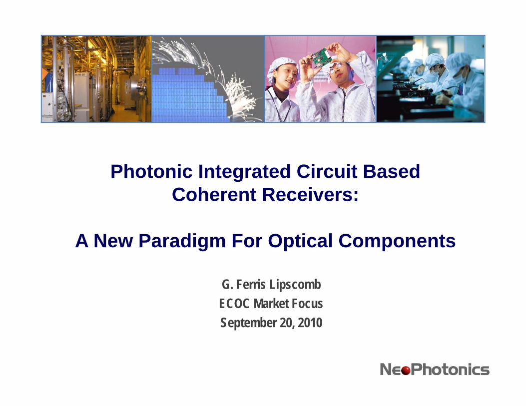
• Advanced Coding Schemes Use Phase Encoding To Allow Multiple Bits Per Symbol–DQPSK–Coherent (DP QPSK)
• Phase Decoding Requires High Performance Interferometers ase ecod g equ es g e o a ce te e o ete sWithin Receivers
• Photonic Integration Is Well Suited To Mass Produce The Required Precision Optical Systemsq p y–PIC DQPSK Demodulators–PIC 90° Hybrids For Coherent Systems
• Hybrid Photonic Integration Based Integrated Receivers• Hybrid Photonic Integration Based Integrated Receivers–Limit Skew Between Optical Paths–High Performance In A Compact Package
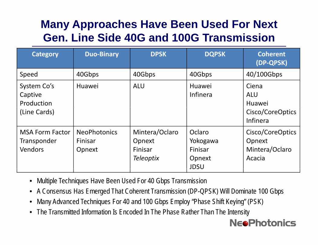
Many Approaches Have Been Used For Next Gen. Line Side 40G and 100G Transmission
Category Duo‐Binary DPSK DQPSK Coherent(DP‐QPSK)
Speed 40Gbps 40Gbps 40Gbps 40/100GbpsSpeed 40Gbps 40Gbps 40Gbps 40/100Gbps
System Co’sCaptive Production
Huawei ALU HuaweiInfinera
CienaALUHuawei
(Line Cards) Cisco/CoreOpticsInfinera
MSA Form Factor NeoPhotonics Mintera/Oclaro Oclaro Cisco/CoreOpticsTransponder Vendors
FinisarOpnext
OpnextFinisarTeleoptix
YokogawaFinisarOpnextJDSU
OpnextMintera/OclaroAcacia
JDSU
• Multiple Techniques Have Been Used For 40 Gbps Transmission• A Consensus Has Emerged That Coherent Transmission (DP-QPSK) Will Dominate 100 Gbps
M Ad d T h i F 40 d 100 Gb E l “Ph Shift K i ” (PSK)• Many Advanced Techniques For 40 and 100 Gbps Employ “Phase Shift Keying” (PSK)• The Transmitted Information Is Encoded In The Phase Rather Than The Intensity
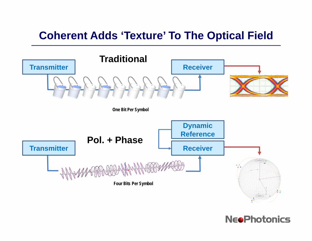
Coherent Adds ‘Texture’ To The Optical Field
Transmitter ReceiverTraditional
DynamicReference
One Bit Per Symbol
Transmitter Receiver
ReferencePol. + Phase
Four Bits Per Symbol
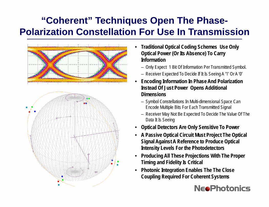
“Coherent” Techniques Open The Phase-Polarization Constellation For Use In Transmission
• Traditional Optical Coding Schemes Use Only Optical Power (Or Its Absence) To Carry Information– Only Expect 1 Bit Of Information Per Transmitted Symbol.– Receiver Expected To Decide If It Is Seeing A ‘1’ Or A ‘0’
• Encoding Information In Phase And Polarization Instead Of Just Power Opens Additional pDimensions – Symbol Constellations In Multi-dimensional Space Can
Encode Multiple Bits For Each Transmitted Signal– Receiver May Not Be Expected To Decide The Value Of The y
Data It Is Seeing• Optical Detectors Are Only Sensitive To Power• A Passive Optical Circuit Must Project The Optical
Signal Against A Reference to Produce Optical Signal Against A Reference to Produce Optical Intensity Levels For the Photodetectors
• Producing All These Projections With The Proper Timing and Fidelity Is CriticalPh t i I t ti E bl Th Th Cl • Photonic Integration Enables The The Close Coupling Required For Coherent Systems
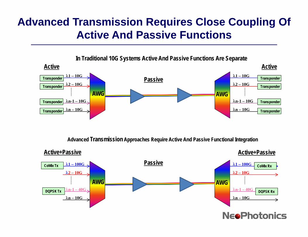
Advanced Transmission Requires Close Coupling Of Active And Passive Functions
ActiveIn Traditional 10G Systems Active And Passive Functions Are Separate
Active
Passive λ1 – 10G
λ2 – 10G
λn-1 – 10G
λ1 – 10G
λ2 – 10G
λn-1 – 10GAWG AWG
Transponder
Transponder
Transponder
Transponder
Transponder
Transponder
λn – 10Gλn – 10G
p
Transponder
p
Transponder
λ1 100Gλ1 100G
Advanced Transmission Approaches Require Active And Passive Functional Integration
PassiveActive+Passive Active+Passive
λ1 – 100G
λ2 – 10G
λn-1 – 40G
λ1 – 100G
λ2 – 10G
λn-1 – 40GAWG AWG
CoMix Rx
DQPSK Rx
PassiveCoMix Tx
DQPSK Txλn – 10Gλn – 10G
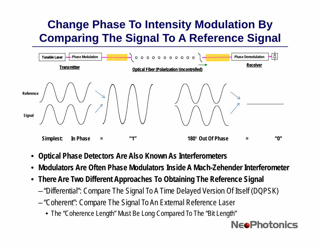
Change Phase To Intensity Modulation By Comparing The Signal To A Reference Signal
Tunable Laser Phase Modulation
Transmitter Receiver
Phase Demodulation
Optical Fiber (Polarization Uncontrolled)
Tunable Laser Phase Modulation
Transmitter Receiver
Phase Demodulation
Optical Fiber (Polarization Uncontrolled)
Reference
Signal
Simplest: In Phase = “1” 180° Out Of Phase = “0”
• Optical Phase Detectors Are Also Known As Interferometers• Modulators Are Often Phase Modulators Inside A Mach-Zehender Interferometer
Simplest: In Phase = 1 180 Out Of Phase = 0
odu ato s e O te ase odu ato s s de ac e e de te e o ete• There Are Two Different Approaches To Obtaining The Reference Signal
– “Differential”: Compare The Signal To A Time Delayed Version Of Itself (DQPSK)“Coherent”: Compare The Signal To An External Reference Laser– Coherent : Compare The Signal To An External Reference Laser• The “Coherence Length” Must Be Long Compared To The “Bit Length”
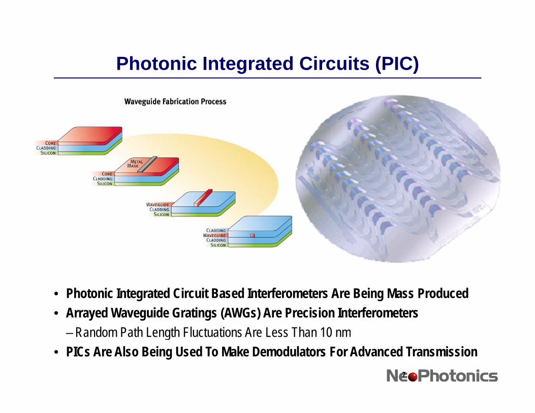
Photonic Integrated Circuits (PIC)
• Photonic Integrated Circuit Based Interferometers Are Being Mass Produced• Arrayed Waveguide Gratings (AWGs) Are Precision Interferometers
–Random Path Length Fluctuations Are Less Than 10 nmRandom Path Length Fluctuations Are Less Than 10 nm• PICs Are Also Being Used To Make Demodulators For Advanced Transmission
7
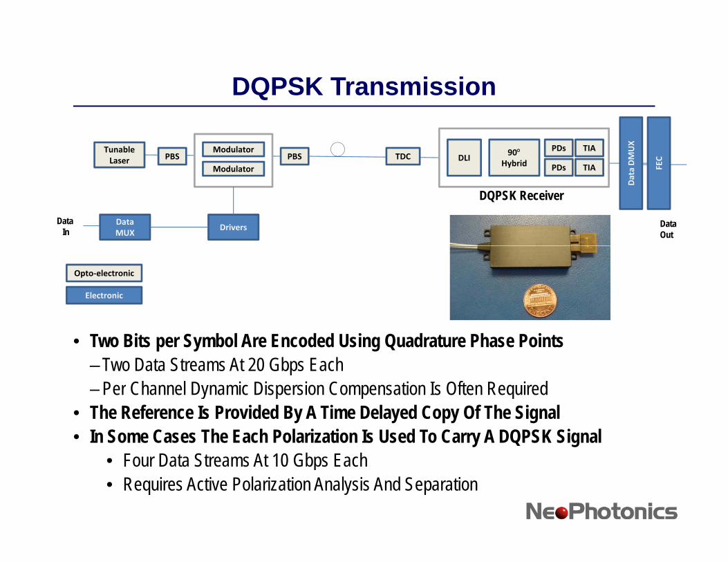
DQPSK Transmission
Tunable Laser
Modulator
ModulatorPBS PBS TDC 90°
Hybrid
PDs
PDs
TIA
TIADLI
FEC
ta DMUX
Data MUX
Drivers
DQPSK Receiver
Data In
Data Out
Dat
Opto‐electronic
Electronic
• Two Bits per Symbol Are Encoded Using Quadrature Phase Points–Two Data Streams At 20 Gbps Each
Per Channel Dynamic Dispersion Compensation Is Often Required–Per Channel Dynamic Dispersion Compensation Is Often Required• The Reference Is Provided By A Time Delayed Copy Of The Signal• In Some Cases The Each Polarization Is Used To Carry A DQPSK Signal
• Four Data Streams At 10 Gbps Each• Four Data Streams At 10 Gbps Each• Requires Active Polarization Analysis And Separation
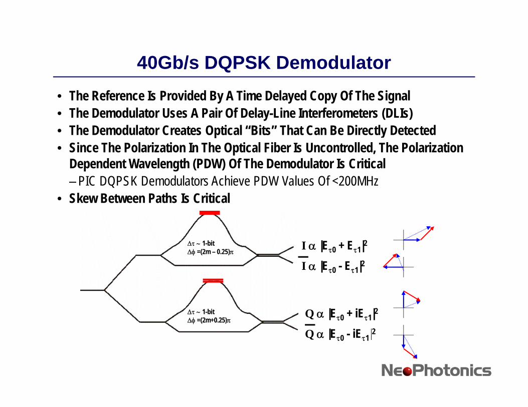
40Gb/s DQPSK Demodulator• The Reference Is Provided By A Time Delayed Copy Of The Signal• The Demodulator Uses A Pair Of Delay-Line Interferometers (DLIs)
Th D d l t C t O ti l “Bit ” Th t C B Di tl D t t d• The Demodulator Creates Optical “Bits” That Can Be Directly Detected• Since The Polarization In The Optical Fiber Is Uncontrolled, The Polarization
Dependent Wavelength (PDW) Of The Demodulator Is CriticalPIC DQPSK D d l t A hi PDW V l Of <200MH–PIC DQPSK Demodulators Achieve PDW Values Of <200MHz
• Skew Between Paths Is Critical
Δτ ∼ 1-bitΔφ =(2m – 0.25)π I α |Eτ0 + Eτ1|2
I α |Eτ0 - Eτ1|2
Δτ ∼ 1-bitΔφ =(2m+0.25)π
Q α |Eτ0 + iEτ1|2
Q |E iE |2Q α |Eτ0 - iEτ1|2
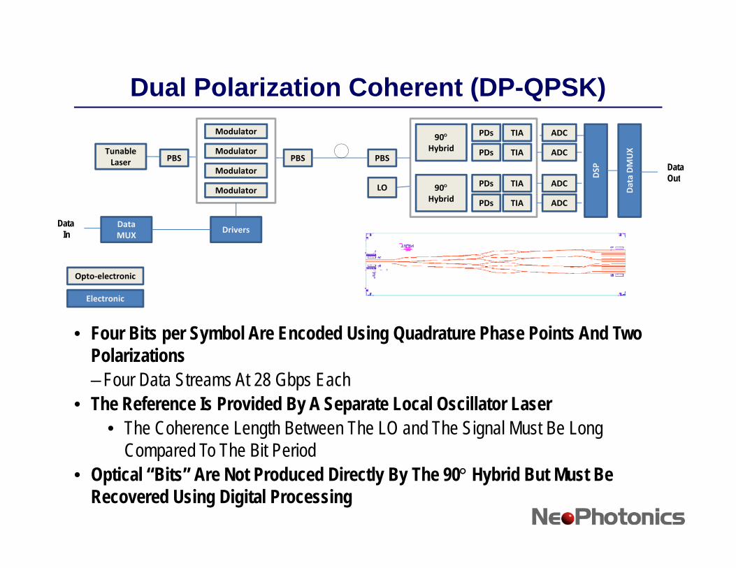
Dual Polarization Coherent (DP-QPSK)
Tunable Laser
Modulator
Modulator
ModulatorPBS PBS PBS
DSP
a DMUX
90°Hybrid
PDs
PDs
TIA
TIA
ADC
ADC
Data Out
Modulator
Data MUX
Drivers
LO
D
Data
90°Hybrid
PDs
PDs
TIA
TIA
ADC
ADC
Data In
Out
Opto‐electronic
Electronic
• Four Bits per Symbol Are Encoded Using Quadrature Phase Points And Two Polarizations–Four Data Streams At 28 Gbps Each
• The Reference Is Provided By A Separate Local Oscillator Laser• The Coherence Length Between The LO and The Signal Must Be Long
Compared To The Bit Period• Optical “Bits” Are Not Produced Directly By The 90° Hybrid But Must Be
Recovered Using Digital Processing
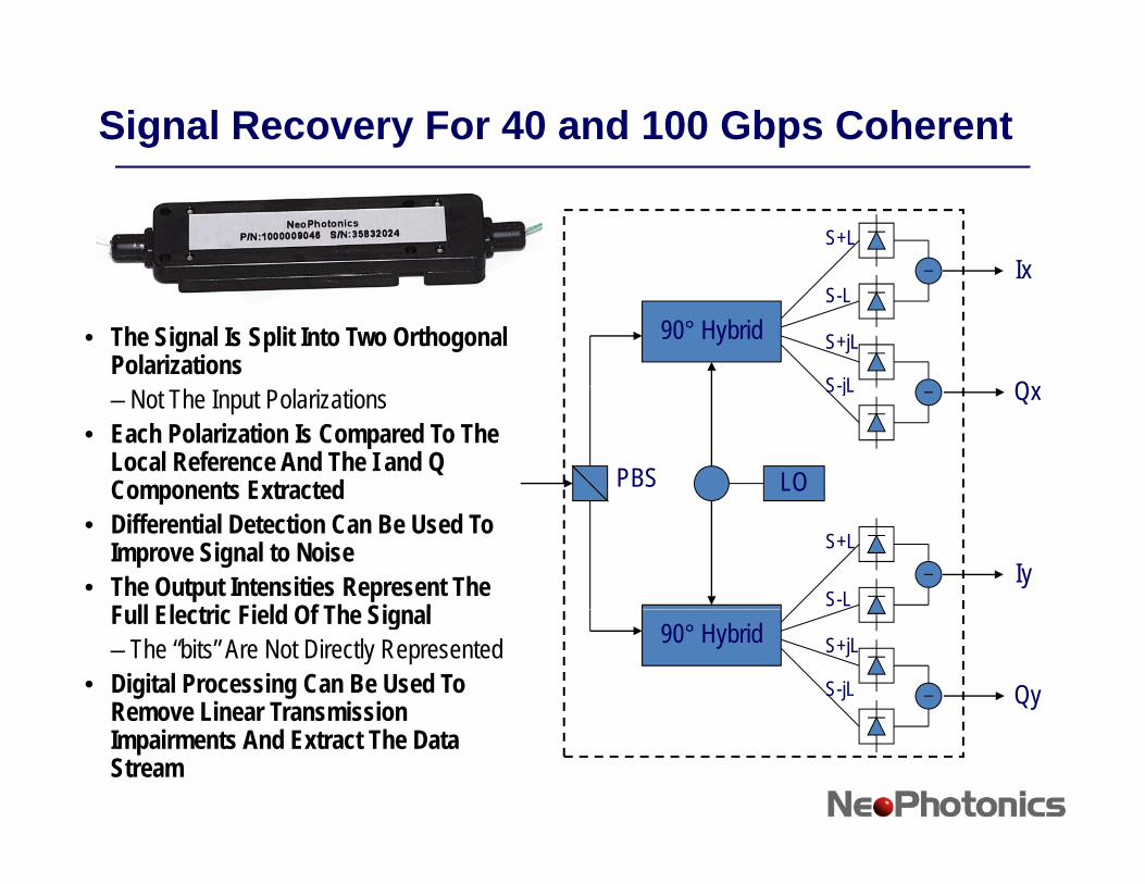
Signal Recovery For 40 and 100 Gbps Coherent
S+LIx
• The Signal Is Split Into Two Orthogonal Polarizations
90° HybridS-L
S+jL
S-jL
Ix
Qx– Not The Input Polarizations• Each Polarization Is Compared To The
Local Reference And The I and Q Components Extracted
S-jL Qx
PBS LOComponents Extracted• Differential Detection Can Be Used To
Improve Signal to Noise• The Output Intensities Represent The
F ll El t i Fi ld Of Th Si l
S+L
S-LIy
Full Electric Field Of The Signal– The “bits” Are Not Directly Represented
• Digital Processing Can Be Used To Remove Linear Transmission
90° Hybrid S+jL
S-jL Qye o e ea a s ss oImpairments And Extract The Data Stream
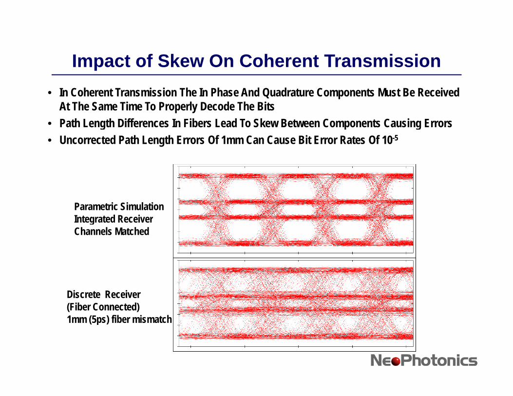
Impact of Skew On Coherent Transmission• In Coherent Transmission The In Phase And Quadrature Components Must Be Received
At The Same Time To Properly Decode The Bits• Path Length Differences In Fibers Lead To Skew Between Components Causing Errors• Path Length Differences In Fibers Lead To Skew Between Components Causing Errors• Uncorrected Path Length Errors Of 1mm Can Cause Bit Error Rates Of 10-5
Parametric SimulationIntegrated ReceivergChannels Matched
Discrete Receiver(Fiber Connected)1mm (5ps) fiber mismatch( p )
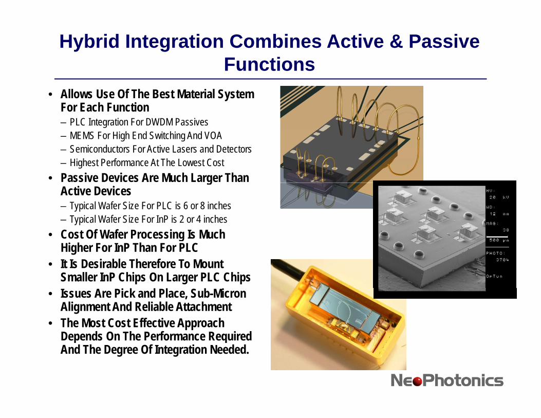
Hybrid Integration Combines Active & Passive Functions
• Allows Use Of The Best Material System For Each Function– PLC Integration For DWDM Passives– MEMS For High End Switching And VOA– Semiconductors For Active Lasers and Detectors– Highest Performance At The Lowest Cost
• Passive Devices Are Much Larger Than gActive Devices– Typical Wafer Size For PLC is 6 or 8 inches– Typical Wafer Size For InP is 2 or 4 inches
• Cost Of Wafer Processing Is Much • Cost Of Wafer Processing Is Much Higher For InP Than For PLC
• It Is Desirable Therefore To Mount Smaller InP Chips On Larger PLC Chips
• Issues Are Pick and Place, Sub-Micron Alignment And Reliable Attachment
• The Most Cost Effective Approach Depends On The Performance Required p qAnd The Degree Of Integration Needed.
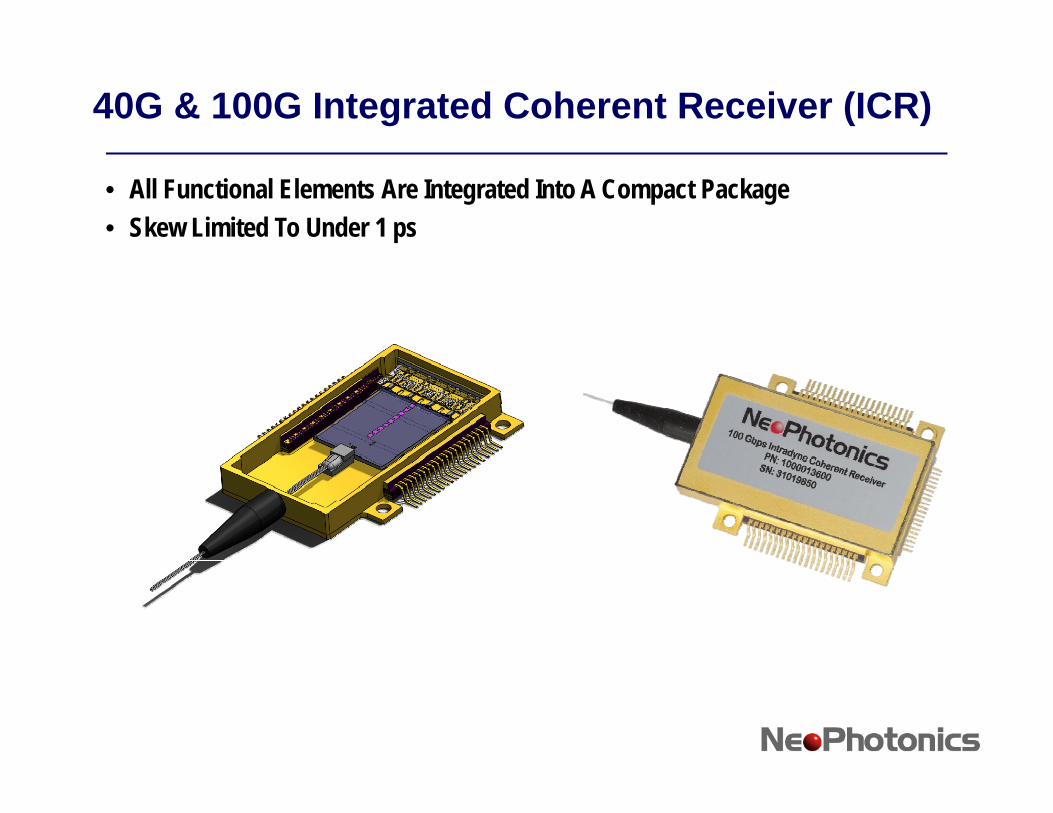
40G & 100G Integrated Coherent Receiver (ICR)
• All Functional Elements Are Integrated Into A Compact Package• Skew Limited To Under 1 ps
Conclusions
• Advanced Coding Schemes Use Phase Encoding To Allow Multiple Bits Per Symbol–DQPSK–Coherent (DP QPSK)
• Phase Decoding Requires High Performance Interferometers ase ecod g equ es g e o a ce te e o ete sWithin Receivers
• Photonic Integration Is Well Suited To Mass Produce The Required Precision Optical Systemsq p y–PIC DQPSK Demodulators–PIC 90° Hybrids For Coherent Systems
• Hybrid Photonic Integration Based Integrated Receivers• Hybrid Photonic Integration Based Integrated Receivers–Limit Skew Between Optical Paths–High Performance In A Compact Package


![Silicon Photonics Circuit Design: Methods, Tools and ... · tlenecks [2,56]. Photonic-electronic co-integration and co-design will make it possible to create integrated photonic-electronic-software](https://img.dokumen.tips/doc/110x75/5e95fd09160d7b469b489eee/silicon-photonics-circuit-design-methods-tools-and-tlenecks-256-photonic-electronic.jpg)