Embed Size (px)
Citation preview

Photon tunneling in a uniaxial crystal film
Wie Quan Zhang
A method for studying photon tunneling in uniaxial crystal films is presented. The complex refractiveindex and the complex angle of refraction of the evanescent wave in a crystal are calculated for the mostgeneral case. The reflectance and transmittance resulting from the tunneling effect in crystal films arediscussed, and the relations among these coefficients and the optical parameters of crystal are found.These relations provide a theoretical basis for characterizing crystal films by means of photon tunneling.© 1998 Optical Society of America
OCIS codes: 170.5280, 310.2790, 310.3840.
1. Introduction
Recently a new technology known as photon-tunnelingmicroscopy was presented. Photon-tunneling micros-copy has high lateral and vertical resolutions. It iswidely used for imaging surfaces of dielectric samples.Zhu1 described the photon-tunneling effect with quan-tum mechanical formalism. Guerra2–4 proposed thetechnology for characterizing the surface of anisotropic-medium film.
In this paper, I discuss the photon-tunneling effectof an anisotropic-medium film. First, using the for-mulas published by Zhang,5,6 I study the complexrefractive index and the complex angle of refractionin a uniaxial crystal for the most general case. Sec-ond, I discuss the complex fields of an evanescentwave. Finally, using the boundary conditions forelectromagnetic fields at the interfaces of the crystalfilm, I find the reflectance and the transmittance forthe tunneling effect, the relations among these coef-ficients, and the thickness and principal refractiveindices of the crystal film.
2. Evanescent Waves in a Uniaxial Crystal
A. Evanescent e-Wave
In Fig. 1, P1 is the interface, I is the incidence plane, OY1is the normal of the interface, ~X1, Y1, Z2! is the incidence-plane coordinate, Z is the optical axis, ~X, Y, Z! is theprincipal-axis coordinate of the crystal, and P2 is the prin-cipal section. The terms a and b are the Eulerian an-
The author is with the Zhejiang Institute of Silk Textiles, Wen yiRoad 88, Hangzhou Zhejiang 310033, China.
Received 27 March 1997; revised manuscript received 21 July1997.
0003-6935y98y010079-05$10.00y0© 1998 Optical Society of America
gles between two coordinates. The direction cosines ofthe refracted e-wave vector and the refractive index canbe found from the following formulas5,6:
n1 sin u1 5 n sin f, (1)
1yn2 5 1yne2 1 ~1yno
2 2 1yne2!S2z, (2)
Sx 5 sin f sin a,
Sy 5 2sin f~cos a sin b 1 cos b cot f!,
Sz 5 sin f~cos a cos b 2 sin b cot f!, (3)
where f and u1 are the angles of refraction and inci-dence, respectively, and n1 is the refractive index ofthe incidence medium.
At total reflection, cot f is complex. Let cot f 5u 1 iv. Equations ~3! become
Sy 5 2sin f~cos a sin b 1 u cos b 1 iv cos b!
5 sin f~sy11 isy2
! 5 sin f sy,
Sz 5 sin f~cos a cos b 2 u sin b 2 iv sin b!
5 sin f~sz11 isz2
! 5 sin f sz, (4)
where sin2 f 5 1y~1 1 cot2 f! 5 1y@1 1 ~u 1 iv!2#.Substituting Eqs. ~4! into Eqs. ~1! and ~2!, whichmakes the real and imaginary parts in Eq. ~1! equal,we get two equations. Simultaneously solving thetwo equations, we get the complex angle cot f ~i.e.,u 1 iv! of refraction and the complex refractive indexn:
u 5 b cos a cos b sin by~1 1 b sin2 b!
vn1 sin u1 5 ne@n12 sin2 u1~cos2 b sin2 a!yne
2
1 ~cos2 a cos2 b 1 sin2 b!yno2
2 ~1 1 b sin2 b!#1y2y~1 1 b sin2 b!, (5)
1 January 1998 y Vol. 37, No. 1 y APPLIED OPTICS 79

where b 5 ~neyno!2 2 1. The electrovector is ε 5 E
exp~ic!, where c is the phase angle. Because Sx1 50, Sy1 5 2cos f, and Sz2 5 sin f,
c 5 konS z r 2 vt 5 kon~Sz2Z2 1 Sy1Y1! 2 vt
5 kon1 sin u1Z2 2 kon1 sin u1~u 1 iv!Y1 2 vt,
where ko 5 2pyl. The first term represents propa-gation parallel to the interface. The second termcorresponds to the propagation of the wave perpen-dicular to the interface ~see Fig. 2!. The third termrepresents the attenuation of the wave perpendicularto the interface ~where Y1 is negative!. The attenu-ation coefficient is kon1v sin u1.
The E vector of the principal-axis coordinate is7
Ek 5 n2Sk~E z S!y~n2 2 nk2!
5 sin fnsk~E z S!y~n2 2 nk2!, k 5 x, y, z, (6)
For the uniaxial crystal nx 5 ny 5 no, nz 5 ne. Equa-tion ~6! becomes
Ex 5 ne2sxszA~E z S!, Ey 5 ne
2syszA~E z S!,
Ez 5 2no2~sx
2 1 sy2!A~E z S!, (7)
Fig. 1. Transformation between two coordinates in a uniaxialcrystal.
Fig. 2. Wave vector, wave front, and ray of an e-evanescent wavein total internal reflection.
80 APPLIED OPTICS y Vol. 37, No. 1 y 1 January 1998
where A 5 1y~ne2 2 n0
2!yszy~sx2 1 sy
2!ysin f. LetA~E z S! 5 Fe1 1 iFe2. The matrix of the electric fieldis
@Ee# 5 @Ae#@Fe1 1 iFe2#. (8)
The magnetic vector is H 5 n S 3 E. In theX–Y–Z coordinate system it is
@H# 5 nF 0Sz
2 Sy
2 Sz0
Sx
Sy2 Sx
0G @E#
5 n sin fF 0sz
2 sy
2 sz
0sx
sy
2 sx
0G @Ae#@Fe1 1 iFe2#
5 n1 sin u1@Be9#@Fe1 1 iFe2#
5 @Be#@Fe1 1 iFe2#, (9)
where @Ae# and @Be# are all complex matrices.
B. Evanescent o-Wave
The direction cosines of the refracted o-wave So in the~X1, Y1, Z2! system are
Sx1 5 0, Sy1 5 2cos f 5 2i~sin2 f 2 1!1y2,
Sz2 5 sin f. (10)
The transformation matrix @L# between the ~X, Y, Z!and ~X1, Y1, Z2! systems is
FXYZG 5 F1
00
0cos bsin b
02sin bcos b
GF cos a0
2sin a
010
sin a0
cos aGFX1
Y1
Z2
G .
(11)
Using Eq. ~11!, we transform So from the ~X1, Y1, Z2!system into the ~X, Y, Z! system. Since E z S 5 0,n Þ nz in Eq. ~6!, so Ez 5 0 and the electrovector is
@Eo# 5 F 2 ~S9y 1 iS0y!yN~S9x 1 iS0x!yN
0G@Eo1 1 iEo2# 5 @Ao#@Eo#,
(12)
where N 5 ~Sx 1 Sy!1y2. Because Sy1 is imaginary,Sy and Sx are all complex. Similarly, we can get thematrix of magnetic field
@Ho# 5 @Bo#@Eo#, (13)
where @Ao# and @Bo# are also complex.
3. Photon-Tunneling Effect in a Uniaxial Crystal Film
There are isotropic media on both sides of the crystalfilm with refractive indices n1 and n3, respectively.In the medium of incidence, the fields of the incidentand reflected waves are Eis, Eip, Ers 5 Ers1 1 iErs2and Erp 5 Erp1 1 iErp2, respectively. For totalinternal reflection the latter are complex. The com-
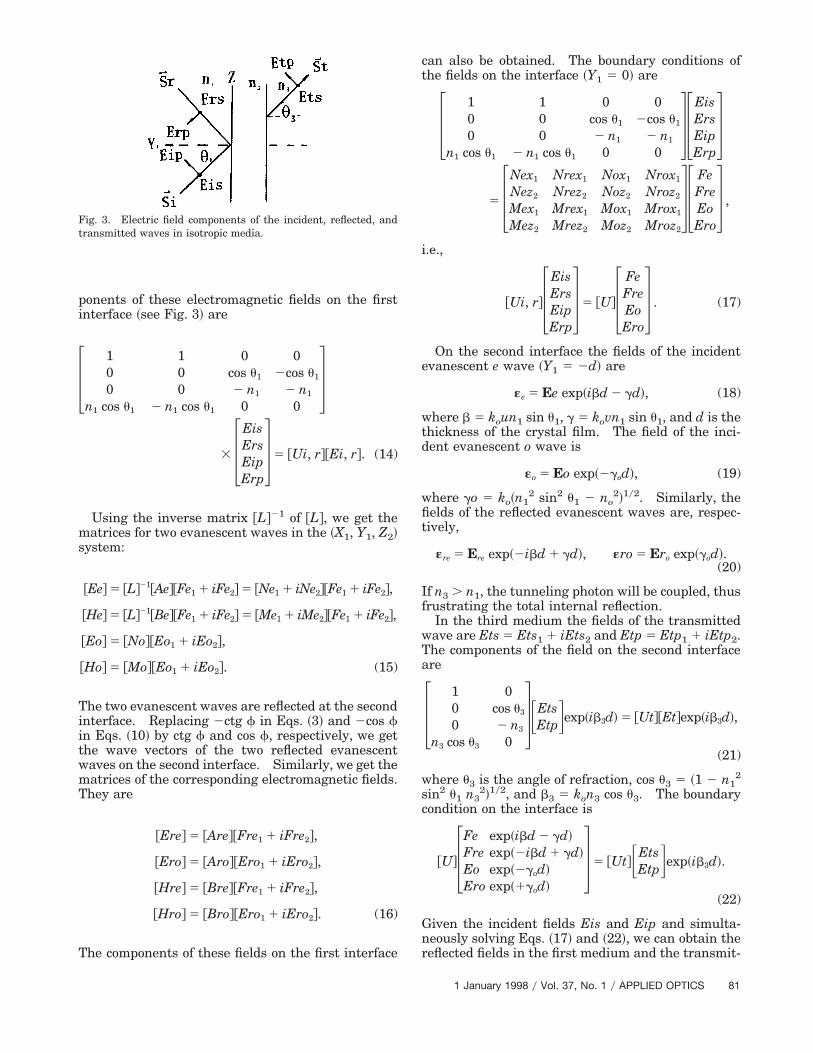
ponents of these electromagnetic fields on the firstinterface ~see Fig. 3! are
3100
n1 cos u1
100
2 n1 cos u1
0cos u1
2 n1
0
02cos u1
2 n1
04
3 3EisErsEipErp
4 5 @Ui, r#@Ei, r#. (14)
Using the inverse matrix @L#21 of @L#, we get thematrices for two evanescent waves in the ~X1, Y1, Z2!system:
@Ee# 5 @L#21@Ae#@Fe1 1 iFe2# 5 @Ne1 1 iNe2#@Fe1 1 iFe2#,
@He# 5 @L#21@Be#@Fe1 1 iFe2# 5 @Me1 1 iMe2#@Fe1 1 iFe2#,
@Eo# 5 @No#@Eo1 1 iEo2#,
@Ho# 5 @Mo#@Eo1 1 iEo2#. (15)
The two evanescent waves are reflected at the secondinterface. Replacing 2ctg f in Eqs. ~3! and 2cos fin Eqs. ~10! by ctg f and cos f, respectively, we getthe wave vectors of the two reflected evanescentwaves on the second interface. Similarly, we get thematrices of the corresponding electromagnetic fields.They are
@Ere# 5 @Are#@Fre1 1 iFre2#,
@Ero# 5 @Aro#@Ero1 1 iEro2#,
@Hre# 5 @Bre#@Fre1 1 iFre2#,
@Hro# 5 @Bro#@Ero1 1 iEro2#. (16)
The components of these fields on the first interface
Fig. 3. Electric field components of the incident, reflected, andtransmitted waves in isotropic media.
can also be obtained. The boundary conditions ofthe fields on the interface ~Y1 5 0! are
3100
n1 cos u1
100
2 n1 cos u1
0cos u1
2 n1
0
02cos u1
2 n1
043
EisErsEipErp
45 3
Nex1
Nez2
Mex1
Mez2
Nrex1
Nrez2
Mrex1
Mrez2
Nox1
Noz2
Mox1
Moz2
Nrox1
Nroz2
Mrox1
Mroz2
43FeFreEoEro
4 ,
i.e.,
@Ui, r#3EisErsEipErp
4 5 @U#3FeFreEoEro
4 . (17)
On the second interface the fields of the incidentevanescent e wave ~Y1 5 2d! are
«e 5 Ee exp~ibd 2 gd!, (18)
where b 5 koun1 sin u1, g 5 kovn1 sin u1, and d is thethickness of the crystal film. The field of the inci-dent evanescent o wave is
«o 5 Eo exp~2god!, (19)
where go 5 ko~n12 sin2 u1 2 no
2!1y2. Similarly, thefields of the reflected evanescent waves are, respec-tively,
«re 5 Ere exp~2ibd 1 gd!, «ro 5 Ero exp~god!.(20)
If n3 . n1, the tunneling photon will be coupled, thusfrustrating the total internal reflection.
In the third medium the fields of the transmittedwave are Ets 5 Ets1 1 iEts2 and Etp 5 Etp1 1 iEtp2.The components of the field on the second interfaceare
3100
n3 cos u3
0cos u3
2 n3
04FEts
EtpGexp~ib3d! 5 @Ut#@Et#exp~ib3d!,
(21)
where u3 is the angle of refraction, cos u3 5 ~1 2 n12
sin2 u1 n32!1y2, and b3 5 kon3 cos u3. The boundary
condition on the interface is
@U#3Fe exp~ibd 2 gd!Fre exp~2ibd 1 gd!Eo exp~2god!Ero exp~1god!
4 5 @Ut#FEtsEtpGexp~ib3d!.
(22)
Given the incident fields Eis and Eip and simulta-neously solving Eqs. ~17! and ~22!, we can obtain thereflected fields in the first medium and the transmit-
1 January 1998 y Vol. 37, No. 1 y APPLIED OPTICS 81

Fig. 4. Relations among the reflectances and transmittances and the thickness d of crystal films ~a! for a CeF3–calcite–CeF3 film ~solidcurve, u1 5 63°; dashed curve, u1 5 80°!, and ~b! for a SiO2–calcite–SiO2 film with u1 5 80.2°.
ted fields in the third medium. The Poynting vectoris
W 5 Re~E 3 H!*. (23)
We can obtain the reflectances ~Rs, Rp! and thetransmittances ~Ts, Tp! of the film for the tunnelingeffect.
As an example, let us calculate the reflectances andtransmittances of CeF3~ZnS!–calcite–CeF3~ZnS! andSiO2–calcite–SiO2 films. For CeF3~ZnS!, the refrac-tive index is n 5 2.4; for calcite, no 5 1.6584 and ne 51.486; for SiO2, n 5 1.7. Assume that the Eulerianangles of both crystals are a 5 0° and b 5 40.1°. Thelimiting angles of the o wave are uT 5 43.7° ~for theformer! and uT 5 77.3° ~for the latter!. Because no .ne, at an incident angle of u1 . uT the e wave is alsoan evanescent wave. Figure 4 shows ~Rs, Rp! and~Ts, Tp! plotted versus dyl for the former at u1 5 63°and u1 5 80° @Fig. 4~a!# and for the latter at u1 5 80.2°@Fig. 4~b!#.
4. Conclusion
I have presented a method for studying photon tun-neling in uniaxial crystal films. The following canbe concluded: ~1! Given the direction cosines of the
82 APPLIED OPTICS y Vol. 37, No. 1 y 1 January 1998
incident wave vector and the optical parameters ofthe crystal film ~the principal refractive indices, theEulerian angles, and the thickness of the crystalfilm!, we can obtain the amplitudes for all evanes-cent fields in the uniaxial crystal for the most gen-eral case. ~2! Using the matrix method, we canobtain the reflectances and transmittances of thefilm for the tunneling effect. In the matrix theelements of the evanescent wave are complex. Wecan find the relation between these coefficients andthe parameters of the crystal film. The penetra-tion depth decreases with an increasing incidentangle and the difference between the refractive in-dex of the crystal and the refractive indices of theisotropic media ~see Fig. 4!. ~3! The sum of thesecoefficients is unity. This result corresponds to thelaw of conservation of energy. These provide a the-oretical base for characterizing a crystal film bymeans of the photon-tunneling effect.
References1. S. Zhu, “Frustrated total internal reflection: a demonstration
and review,” Am. J. Phys. 7, 801–607 ~1986!.2. J. M. Guerra, “Super-resolution through illumination by
diffraction-born evanescent waves,” Appl. Phys. Lett. 66, 3555–3557 ~1995!.
3. J. M. Guerra, “Photon tunneling microscopy of polymeric sur-faces,” Science 262, 1395–1400 ~1993!.
4. J. M. Guerra, “Photon tunneling microscopy,” Appl. Opt. 29,3741–3752 ~1990!.
5. W.-Q. Zhang, “General ray-tracing formulas for crystal,” Appl.Opt. 31, 7328–7331 ~1992!.
6. W.-Q. Zhang and Y.-M. Zhuo, “Design and application of a bi-focus lens,” Appl. Opt. 32, 4204–4208 ~1993!.
7. W.-Q. Zhang, “Reflectance, transmittance and total internal reflec-tion in biaxial crystal,” Optik ~Stuttgart! 104, 67–71 ~1997!.
1 January 1998 y Vol. 37, No. 1 y APPLIED OPTICS 83