Embed Size (px)
Citation preview

Service ManualPhilips Domestic Appliances and Personal Care
Published by Philips Domestic Appliances and Personal Care Printed in the Netherlands © Copyright reserved Subject to modification
Wardrobe Care
GC9920
07/01
PRODUCT INFORMATION
Safety Information- This product meets the requirements regarding
interference suppression on radio & TV.- After the product has been repaired, it should function
properly and has to meet the safety requirements & legal regulations as laid down & officially established at this moment.
FeaturesIron- Careeza soleplate with pointed tip- Power on switch cum iron ready lamp- Iron ready in 2 mins- Auto shut off in 5 mins- Suction & blowing button for active board- Steam trigger- Heel rest- Iron hose cord 1.6 m
Steamer- Internal heating element- Power on switch cum steamer ready lamp- Steamer ready in 2 mins- Auto shut off in 5 mins- Suction & blowing button for active board- Steam trigger- Steamer hose cord 1.8 m
Ironing Board- Non-scorch board cover- Active & passive boards (Longer portion is the Active
board)- Special shape on Active board for shirt & blouse- Refresh button on Active board for refresh mode
(Auto shut off in 10 mins)- Heater on Active board- Bi-directional fan on Active board for blowing & suction- Board tilting mechanism- Board folding & locking strap for storage & transport- Height adjustment for board 0.75 m to 1.00 m in
22 intermediate steps- Rod hanger for steamer mode
Stand- Automatic calc-cleaning system (2 mins to complete)- Boiler 4.5 bar- Heat resistant storage compartment for iron & steamer- Retractable auto cord-winder 3.5 m effective length- Wheels for ease of mobility- Detachable water tank 2.5 L- Detachable rinse tank 0.85 L- LED lamp for power-on, water tank & rinse tank

GC9920
2-17
TECHNICAL INFORMATION
- Power Maximum : 2400 W at 240 V, 10 A Boiler : 1200 W Iron : 800 W Steamer : 500 W Board heater : 400 W Fan : 40 W
- Voltage : 230 V
- Frequency : 50 - 60 Hz
- Weight (product) : 20 kg
- Weight (with package) : 24 kg
- Product dimensions : 500 x 480 x 760 mm (L x W x H)in storage mode
Start-up timeApproximate 2 minsApproximate 5 mins if automatic calc-cleaning is required
Board coverThe non-scorch cover can withstand 230 deg C continuously for 45 mins. This allows iron to be rested horizontally on the cover during ironing.
Board heatingHeater is provided only in the active board. On the board cover, the feeling is warmth (< 60 deg C) & not scalding hot. For optimized performance of the appliance, the heater is permanently on during steamer & refresh mode while switches with iron during ironing mode.
Active ironing boardThe ironing board has 2 portions: Passive & Active board. The longer portion is the Active board. The Active board is specially shaped for shirt or blouse during ironing, steamer & refresh mode. It also has a bi-directional fan & board heater that offers suction or blowing & board heating during use. For optimized performance of the appliance, fan is permanently on during use.
Refresh modeDuring refresh mode, warm air blows out from the air vent at the side of the active board housing. The refresh mode runs for 10 mins & then switches off automatically. You can repeat the refreshing by pressing the refresh button again.
Automatic calc-cleaning systemWhen the power-on light blinks, automatic calc-cleaning is active. Wait 2 mins for the appliance to complete the calc-cleaning process. After calc-cleaning is completed, the rinse tray light blinks & a few beeps can be heard. Empty the rinse tray & re-insert it. The 0.85 L detachable rinse tank has suffi cient capacity for 1 rinse (rinse volume 0.55 L) with buffer to avoid spillage while transporting to empty the contents.During automatic calc-cleaning, the appliance is disabled until the process is completed.
Indicator lamp
All switch-cum-lamps on the appliance use blue LED. For the iron & steamer light, the LED fl ashes during heat up & burn steadily when ready. The power-on light on stand will remain lit as long as the appliance is plugged in & the main switch is on.
Appliance power management schemePlease take note that the following combinations cannot be operated simultaneously:Iron mode + Steamer modeIron mode + Refresh mode
GC9920
3-17
DISASSEMBLY ADVICE - IRONING BOARD
FAN GRILLE 3
FAN GASKET 4
FAN ASSY 5
Remove bolts A1 - A4Disassemble FAN GRILLE 3Disconnect 4-pole cable of FAN ASSY 5Disassemble FAN ASSY 5Disassemble FAN GASKET 4
Reassembly tip:Ensure fan assy orientation - light blue colour fan label to face board frame
BOARD HOUSING ACTIVE 7
Remove BOARD STICKER 14 (on active board)Remove screws B1 - B20Remove board plugs C1 - C3Disassemble BOARD HOUSING ACTIVE 7
Reassembly tip:Adjust board plug C1, C2, C3 clockwise & counter-clockwise to align screw holes between board frame & board housing before screwing.C1: adjustment B1 - B6C2: adjustment B7 - B12C3: adjustment B13 - B14
Reassembly tip:Replace with new BOARD STICKER 14 after reassembling BOARD HOUSING ACTIVE 7
BOARD HEATER 1
BOARD TCO/FUSE 2
Remove heater terminal connections D1, D2Unbend heater tabs E1 - E7Disassemble Board heater
Disassembly tip:Do not over-bend heater tabs to prevent breakage
Reassembly tip:The slot holes on the heater tab & board frame are for riveting. Use rivets SUS dia 3.2 x 6.35 & rivet gun when reassembling BOARD HEATER 1
Remove rivets F1, F2Disassemble BOARD TCO/FUSE 2
Reassembly tip:Use rivets SUS dia 3.2 x 6.35 & rivet gun when reassembling BOARD TCO/FUSE 2
KNOB FLAP 10
KNOB 11
Remove screws G1, G2Disassemble KNOB FLAP 10Disassemble KNOB 11
COVER BUTTON REFRESH 12
BUTTON REFRESH ASSY 13
Disassemble COVER BUTTON REFRESH 12 (rotate anticlockwise)Remove screws H1, H2Remove wire studDisconnect 2-pole cable of BUTTON REFRESH ASSY 13Disassemble BUTTON REFRESH ASSY 13
PARTS LIST - IRONING BOARD
Pos Service code Description Remark
123
4
567
8
9101112
1314
55
4239 010 096904239 017 100804239 026 228204239 026 259104239 015 56230
4239 017 100904239 017 101004239 026 227504239 026 258704239 026 22830
4239 010 097504239 026 228404239 026 227604239 026 227804239 026 25880
4239 021 332804239 026 228104239 026 259004239 016 82220
Board heaterTCO/Fuse boardFan grille (purple)Fan grille (blue)Fan gasket
Fan assyBoard coverBoard housing active (purple)Board housing active (blue)Button tilt (dark grey)
Rod hangerKnob fl ap (dark grey)Flap (dark grey)Cover button refresh (purple)Cover button refresh (blue)
Button refresh assyBoard sticker (purple)Board sticker (grey)Board heater rivet
By orderBy order

GC9920
4-17
EXPLODED VIEW - IRONING BOARD
2
1
11
14
9
12
7
6
8
4
5
3
D1
C3
C1
B12B11
B10
B9B8
B7
F2F1 B15
B16B17
B18B19
B20
Heater tab positions
C2
A1 - A4H1
G2
G1
H2
D2
E1
E7
E3
E5
E2
E4
E6B6B5
B4
B13
B14
B3B2
B1
13
10
GC9920
5-17
DISASSEMBLY ADVICE - MOVING COLUMN
MOVING COLUMN ASSY 15
PLATE PIVOT FLANGE LEFT 16
PLATE PIVOT FLANGE RIGHT 17
HANDLE LIFT LEFT 18
HANDLE LIFT RIGHT 19
Remove screws M1 - M4Disassemble BACK COVER TOP 21Remove screw S1Remove screws T1, T2, T9, T10Disassemble PANEL LEFT ASSY 24Disconnect 4-pole cable W4, 2-pole cable W5, Quick-connectors L3, N3 & Earth (Board heater) on STAND LECTRONICS 37
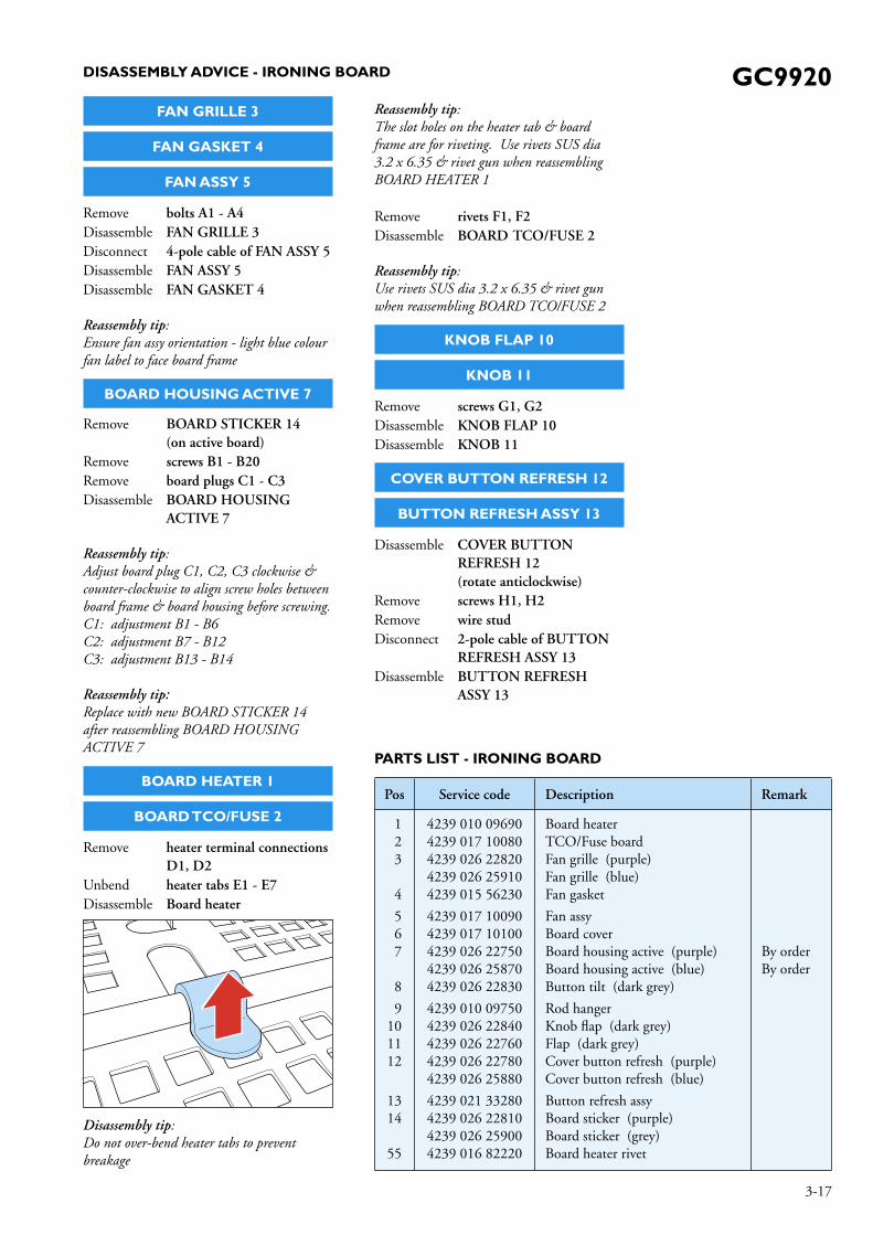
Undress the disconnected wires so that their ends are hanging freely from position Loc 1:
Loc 1
Remove screw M5Press HANDLE LIFT LEFT 18 & HANDLE LIFT RIGHT 19Pull upwards IRONING BOARD-MOVING COLUMN assy, detaching completely from the Stand.Place IRONING BOARD-MOVING COLUMN upside down, lying fl at on ironing board surface as follows:
Unhook 2x straps from the springs as follows:
Strap 1
Strap 2
Spring 1
Spring 2

GC9920
6-17
DISASSEMBLY ADVICE - MOVING COLUMN
Remove screws J1, J2Disassemble PLATE PIVOT FLANGE LEFT 16Disassemble PLATE PIVOT FLANGE RIGHT 17Remove screws K1, K2Disassemble HANDLE LIFT LEFT 18Disassemble HANDLE LIFT RIGHT 19Remove T10 Torx screws L1 - L8Cut 3x cable ties to free the wires on MOVING COLUMN ASSY 15
Disassemble MOVING COLUMN ASSY 15

GC9920
7-17
EXPLODED VIEW & PARTS LIST - MOVING COLUMN
15
19
17
18
16
J2K2
K1L1
L2
L4 L3
J1
L5
L8
L6
L7
Pos Service code Description Remark
1516171819
4239 020 013504239 026 229204239 026 229304239 026 229404239 026 22950
Moving column assyPlate pivot fl ange left (dark grey)Plate pivot fl ange right (dark grey)Handle lift left (dark grey)Handle lift right (dark grey)
By order

GC9920
8-17
DISASSEMBLY ADVICE - STAND
WHEEL ASSY 31
CAP WHEEL PAINTED 32
E-RING 33
Disassemble CAP WHEEL PAINTED 32Disassemble E-RING 33Disassemble WHEEL ASSY 31
BACK COVER TOP 21
BACK COVER BOTTOM 22
AUTO CORD WINDER 38
Remove screws M1 - M4Disassemble BACK COVER TOP 21Remove screws N1 - N6Disassemble BACK COVER BOTTOM 22Remove screws P1, P2, P3Disconnect quick-connectors E, L, N at the back of AUTO CORD WINDER 38Disassemble AUTO CORD WINDER 38
SPRING LIFT COLUMN ASSY 27
Remove IRONING BOARD-MOVING COLUMN assy (refer DISASSEMBLY ADVICE- MOVING COLUMN)Remove screws Q1, Q2Disassemble SPRING LIFT COLUMN ASSY 27
FOOT ASSY 28
Remove screws R1 - R4Disassemble FOOT ASSY
PANEL LEFT ASSY 24
SMPS 36
STAND ELECTRONICS 37
WIRE ASSY LED - STANDBY 39
WIRE ASSY LED - WATER TANK 41
Remove screw S1Remove screws T1, T2, T9, T10Disassemble PANEL LEFT ASSY 24Disconnect quick-connector W7 on STAND ELECTRONICS 37Remove LED coverDisassemble WIRE ASSY LED - STANDBY 39Disconnect quick-connector W8 on STAND ELECTRONICS 37Disassemble WIRE ASSY LED - WATER TANK 41Remove screw UDisconnect quick-connectors L4, N4 & 4-pole cable W3 on STAND ELECTRONICS 37Disassemble SMPS 36Remove screw VDisconnect all connectors on STAND ELECTRONICS 37Disassemble STAND ELECTRONICS 37

GC9920
9-17
WIRE LABELS ON STAND ELECTRONICS 37
AB
C
GF
D
E
SteamerLive
Brown (L2)
SteamerComm
Black (W2)
RefreshSwitch
PCB (W5)
BoardHE-Fuse
Brown (L3)
BoardHE-FuseBlue (N3)
SMPSLive
Brown (L4)
SMPSNeutral
Blue (N4)
Rinse tank switchBlack andGray (W9)
Water tank LEDYellow andBlack (W8)
Rinse tank LEDRed and Black (W6)
ReedSwitch
White (W10)
SteamerNeutral
Blue (N2)
IronNeutral
Blue (N1)
IronLive
Brown (L1)
IronComm
Black (W1)
ThermistorBlue and
Orange (W11)
Fan4x wire
Red (W4)
Standby LEDBlue and
Black (W7)
Cord winderNeutral
Blue (N5)
Cord winderLive
Brown (L5)
SMPS 24V/5V4 x wire
Black (W3)
ABC (brown, red, and blue) is a 3 pole connector toconnect to boiler side. (W12)DEFG (white, blue, yellow and black) is a 4 pole connto connect to boiler side (W13)
NOTE :
GC9920
10-17
PANEL RIGHT ASSY 25
REED SWITCH ASSY 29
IRON SLIDING TRAY ASSY 30
STEAMER ASSY 47
Remove screw S2Remove screws T3, T4, T11, T12Disassemble PANEL RIGHT ASSY 25Disconnect quick-connector W10 on STAND ELECTRONICS 37Disassemble REED SWITCH ASSY 29Release catch at bottom of IRON SLIDING TRAY ASSY 30Pull out completely IRON SLIDING TRAY ASSY 30Remove T5, T6, T7, T8Disassemble Boiler compartmentDisconnect steam hose of HOSE CORD STEAMER 48 on EV1Disconnect steamer Earth & quick-connectors L2, N2, W2 on STAND ELECTRONICS 37Disassemble STEAMER ASSY 47
IRON ASSY 43
HOSE CORD IRON 46
Remove screw WDisassemble BackplateDisconnect quick-connectors of HOSE CORD IRON 46 at iron rearDisassemble IRON ASSY 43
SOLEPLATE ASSY 44
IRON ELECTRONICS 45
Disassemble InlayRemove screws X1 - X3Disassemble IRON ELECTRONICS 45Remove screws Y1 - Y3Disassemble HousingRemove screws Z1 - Z3Disassemble CoverDisassemble SOLEPLATE ASSY 44
PANEL FRONT BOTTOM 26
WIRE ASSYLED - RINSE TANK 40
WIRE ASSYRINSE TANK SWITCH 42
CHASSIS BOILER ASSY 49
PUMP ASSY 50
ELECROVAVLE 51
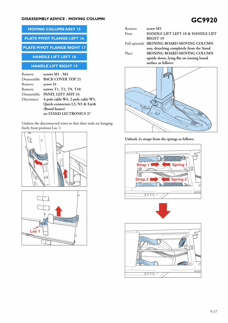
Remove RINSE TANK ASSY 35Disassemble PANEL FRONT BOTTOM
Disassembly tip:Release 2x catches at the bottom of boiler chassis by inserting 2x screws (M4x8) into the holes located at Loc 2 & Loc 3
Refer following diagram.
Lock 2
Lock 3Boiler chassis
Disconnect 3-pole cable W12 and 4-pole cable W13Disconnect boiler Earth, W6, W9, W11Disconnect steam hoses & connections on ELECTROVALVE 51 (EV1, EV2, EV3)Disconnect De-air tube, Inlet tube, Safety capRemove Screws a1 & a2Release 2x catches at the Boiler chassis
Releasecatch
Releasecatch
Pull outchassis
Boilerchassis
a1
a2
Pull out CHASSIS BOILER ASSY 49Disassemble WIRE ASSY LED - RINSE TANK 40Disassemble WIRE ASSY RINSE TANK SWITCH 42Disassemble PUMP ASSY 50Disassemble ELECTROVALVE 51
DISASSEMBLY ADVICE - STAND

GC9920
11-17
1. Due to the high wattage of the product, only the specifi ed cordset must be used.
2. When replacing the ELECTROVALVE 51, please be reminded to apply loctite at the joints for good sealing.
3. After the product is repaired, it should function properly & must meet the safety requirements & legal regulations as laid down & offi cially established at this moment.
4. Basic checks for the STAND ELECTRONICS 37 as follows:
4.1 Check for incoming AC voltage measured at L5 and N5 (220 - 240 V AC)
220 - 240 V ACN5
L5
4.2 Check for output of 24 V DC and 5 V DC from switch mode power supply.To check 24 V DC : Probe at 24 V test point and N1/N2/N3.
24V
24 V DCN3
N2
N1
REPAIR INSTRUCTIONS
To check 5 V DC :1) Probe at 5 V test point and N1/N2/N3. or2) Probe at connector 9019 between VDD and GND
5 V DC2)
5 V DC1)
N3
N2
N1
4.3 Check for AC power supply to Iron unit between L1 and N1 (220 - 240 V AC)
4.4 Check for AC power supply to Steamer unit between L2 and N2 (220 - 240 V AC)
Steamer220 - 240 V AC
N2
N1
L1L2
Iron220 - 240 V AC
5.1 The calc clean process will automatically activate after 3.5 hrs of steaming. In terms of product usage time, it would depend on how often the consumer uses steam when he/she uses the product.
5.2 It is possible for service center to manually activate Auto Calc Clean process before time is due.The steps involved are as follows: - Unplug cordset from mains socket. - Allow boiler to cool down.
(Boiler temperature must be < 50 Deg C for auto calc clean to take place)
- Press & hold refresh button when plugging into the mains socket.
- Release refresh button when power-on light starts blinking, indicating that calc clean process is active.

GC9920
12-17
PARTS LIST - STAND, IRON ASSY, STEAMER & BOILER
BLOCK DIAGRAM
STAND ELECTRONICSCONTROLLER
IRON
BOILER
STEAMER
SMPS
FAN
BOARDHEATER
PUMP
IRON E-VALVE
STEAMER E-VALVE
RINSE E-VALVE
MAINSPLUG
24 V DC, GND,DIR Sig, PWM Sig
STEAMER CORDL,N,E,COMM4x Conductor
IRON CORDL,N,E,COMM4x Conductor
24 V DC, 5 V DC, 2x GND4x Conductor
L,N2x Conductor
4x Conductor
L, N
2x Conductor
3x Conductor
Note: CONN means Signal wire
Pos Service code Description
2021222324
2526272829
3031323334
3536
37
4239 016 818804239 026 230904239 026 231004239 021 342304239 021 33550
4239 021 335604239 026 230804239 021 338404239 021 334704239 017 74040
4239 021 335304239 026 228504239 021 342204239 016 818904239 021 33570
4239 021 384204239 021 336004239 021 34370
4239 021 34350
Boiler strapBack cover top (grey)Back cover bottom (dark grey)Steamer door hot foiledPanel left assy
Panel right assyPanel front bottom (grey)Spring lift column assyFoot assyReed switch assy
Iron sliding trayWheelCap wheel paintedE-ring ID 10Water tank assy (purple)
Water tank assy (blue)Rinse tank assy24 V SMPS(Switch Mode Power Supply)Stand electronics
Pos Service code Description
38
3940
414243
44
454647
48
4950515253
54
4239 021 335204239 021 383704239 021 383804239 017 742204239 017 74210
4239 017 742304239 017 742404239 020 013804239 020 018104239 021 34630
4239 021 338604239 021 342704239 020 013304239 020 016104239 021 34290
4239 020 013204239 017 098804239 017 098904239 026 229104239 015 56700
4239 026 23020
Auto cord winder (EU)Auto cord winder (Swiss)Auto cord winder (UK/SIN)Wire assy LED - StandbyWire assy LED - Rinse tank
Wire assy LED - Water tankWire assy rinse tank switchIron assy (without hose cord iron)Iron assy BlueSoleplate assy 230 V / 800 W
Iron electronicsHose cord ironSteamer assySteamer assy BlueHose cord steamer
Chassis boiler assyPump service packElectrovalveFoot padWheel tread
Boiler compartment cover
= changed
GC9920
13-17
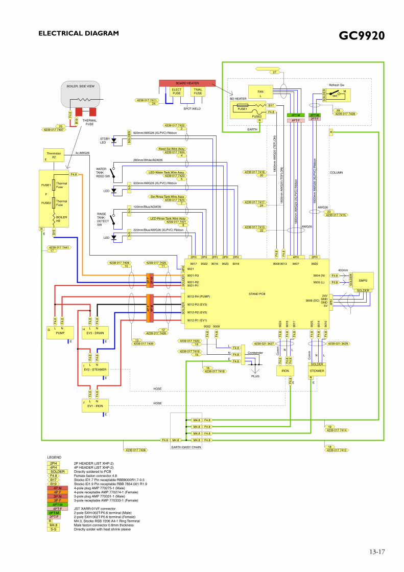
ELECTRICAL DIAGRAM
F4.8F
4.8
224239 017 7413
24
F4.8
B17
4239 017 7417
204239 017 7416
27
COLUMN
HOSE
HOSE
AWG26
AWG26
F4.
8
400mm
N
EE
E
N
LL
Com
m
N L
Com
m
SOLDER
STEAMERIRON
PLUG
LEGEND
4P HEADER (JST XHP-2)Directly soldered to PCBFemale faston connector 4.8Stocko ID1.7 Pin receptable RBB8000R1.7-0.5Stocko ID1.9 Pin receptable RBB 7854.001 R1.94-pole plug AMP 770275-1 (Male)4-pole receptable AMP 770274-1 (Female)3-pole plug AMP 770331-1 (Male)3-pole receptable AMP 770333-1 (Female)
JST XARR-01VF connector2-pole SXH-002T-P0.6 terminal (Male)2-pole SXH-002T-P0.6 terminal (Female)M4.3, Stocko RSB 7206 A4-1 Ring TerminalMale faston connector 0.8mm thicknessDirectly solder with heat shrink sleeve
2P HEADER (JST XHP-2)
Cordwinder
SMPS
SOLDER
SO
LDE
R
SO
LDE
R
4PH
4PT-M 2PT-M
4PT-F2PT-F
1800
mm
AW
G20
(T
EF
LON
)
1800
mm
AW
G20
(T
EF
LON
)
1800
mm
AW
G24
(X
LPV
C)
Rib
bon
1600
mm
AW
G26
(X
LPV
C)
Rib
bon
F4.8F
4.8
F4.
8
B19
F4.
8
F4.
8
F4.
8
F4.
8F
4.8
F4.
8F
4.8
F4.
8
F4.
8
F4.
8
2PH4PH2PH 2PH 2PH 2PH 2PH
9024
9015
9011
9025
9014
9010
24VGND9006 (DC)
9005 (L)
9004 (N)
GND5V
902090079008
9021
9002 9009
9001-R3
9001-R29001-R1
9012-R4 (PUMP)
9012-R3 (EV3)
9012-R2 (EV2)
9012-R1 (EV1)
9017 9022 9016 9023 9018
STAND PCB
9013
4239 017 7415
4239 021 34294239 021 3427
R
Refresh Sw
R
EARTH
BD HEATER
23
4239 017 741816
4239 017 741218
4239 017 7406
4239 017 742828
M
tact
FUSE1
FUSE2
FANL
SO
LDE
RS
OLD
ER
4PH
F4.8
F4.8
F4.8
F4.8
F4.8
144239 017 7420
154239 017 7419
M4.8
M4.8
EARTH DAISY CHAIN
F4.8M4.8
F4.8M4.8
F4.8M4.8
R
ELECTFUSE
T'MALFUSE
BOARD HEATER
24
SPOT WELD
4239 017 7411
4239 017 741419
4239 017 74254239 017 740811
4239 017 742612
10
4239 017 744117
SO
LDE
R
STDBYLED
620mm/AWG26 (XLPVC) Ribbon
4x AWG26
4239 017 7422S
-S
WATERTANKREED SW
LED
500mm/AWG26 (XLPVC) Ribbon
280mm/White/AGW26
4239 017 7423LED-Water Tank Wire Assy
5
4239 017 7404Reed Sw Wire Assy
4
2S
-SS
-S
RINSETANKDETECTSW
LED
220mm/Blue/AWG26 (XLPVC) Ribbon
100mm/Blue/AGW26
4239 017 7421LED-Rinse Tank Wire Assy
8
4239 017 7424Sw-Rinse Tank Wire Assy
7
F4.
8
F4.
8
L N
E
PUMPG
F4.
8
F4.
8
LH N
E
EV3 - DRAIN
F4.
8
F4.
8
LI N
E
EV2 - STEAMER
ThermalFuse
BOILERHE
FUSE2
F
FUSE1ThermalFuse
ThermistorX2
E
F4.8
R
E
3P F
3P M
4P F
4P M
F4.
8
F4.
8
LJ N
E
EV1 - IRON
4239 017 740913
BOILER, SIDE VIEW
B19
F4.
8
4239 017 740725
THERMALFUSE
F4.8B17B19
4PH
RM4.8S-S
2PH
SOLDER
4P M4P F3P M3P F
4PT-M4PT-F
2PT-M2PT-F

GC9920
14-17
EXPLODED VIEW - STAND
21
39
36
37
30
35
52
54
23
27
24
26
34
29
LED cover
U
V
R1R2
R3 R4
32
31
33
53
38
22
28
25
Q1
Q2S2
M1
M2
N2
N1
T6
T5
T11
T12
N4
N6N5
N3
M3
M4
T3
T1T2
T4
T8
T7
T10
T9
41
P1
P3
P2
S1
M5

GC9920
15-17
EXPLODED VIEW - IRON ASSY
Inlay
45
44
43
46
Cover
X2X3
Y2
Y3
WX1
Z3
Z2
Y1
Backplate
Housing
Z1

GC9920
16-17
EXPLODED VIEW - STEAMER
48
47

GC9920
17-17
EXPLODED VIEW - BOILER
51
20
49
50
40
42
Safetycap Inlet tube
EV3
EV2
EV1
Rinseoutlettube
De-air tube
Braidedtube


![Untitled-1 [] · Truva KONÖNAL 000 EPETL . LltLi Masas / Ironing Board Optima KONÖNAL oo o . Lltü Masas / Ironing Board Simge KONÖNAL eee EPETL [ltü Msasast / Ironing Electra](https://img.dokumen.tips/doc/110x75/6024c5ed25ccc9167a48fc73/untitled-1-truva-konnal-000-epetl-lltli-masas-ironing-board-optima-konnal.jpg)