Embed Size (px)
Citation preview
PHD2 v2.6.5
User Guide
April 30, 2018
24556677788899
10101111111212121313151515161718191919192021212222232427282929313131343434343535363738383838383943
Table of Contents
Table of ContentsIntroductionMain Screen
Basic controlMenusStatus Bar
Using PHD2 GuidingEquipment Connection
Camera SelectionSupport for SBIG Dual-chip CamerasASCOM Camera PropertiesMultiple Cameras of the Same TypeMount SelectionAux Mount SelectionBenefits of Using ASCOM (or INDI) connectionsAdaptive Optics and Rotator SelectionsSimulatorsEquipment ProfilesNew-Profile-Wizard
Exposure Time and Star SelectionAutomatic Calibration
Conventional MountsAdaptive Optics Devices
GuidingDark Frames and Bad-pixel Maps
IntroductionDark FramesBad-pixel Maps (Defect Maps)
Step-by-Step Guide to Refining a Bad-pixel MapReusing Dark Frames and Bad-pixel Maps
Visualization ToolsOverlaysGraphical DisplayStatsStar Profile and Target DisplaysAdaptive Optics (AO) GraphDockable/Moveable Graphical Windows
Advanced SettingsGlobal TabCamera TabGuiding TabAlgorithms Tab
Declination Backlash CompensationUni-directional Declination Guiding
Other Devices TabGuide Algorithms
Guiding TheoryGuide Algorithm Parameters
Tools and UtilitiesManual GuideAuto-Select StarCalibration DetailsPHD2 ServerDitheringLogging and Debug OutputPolar Alignment ToolsDrift Alignment ToolStatic Polar Alignment ToolPolar Drift Alignment ToolLock PositionsComet TrackingGuiding AssistantStar-Cross Tool
2

43434445454546
474848515152525253535454555555606262
6262656869
Managing Equipment ProfilesAux-Mount Connection using "Ask for coordinates"Advanced Settings for the SimulatorsMultiple Program ExecutionsKeyboard ShortcutsSoftware Update
Checking for updatesTable of PHD2 keyboard shortcutsTrouble-shooting and Analysis
Calibration and Mount Control ProblemsDisplay Window ProblemsHot-pixel ProblemsRestoring a Working BaselineCamera Timeout and Download ProblemsPoor Guiding PerformanceAlert MessagesLog Analysis
Guiding Log ContentsProblem Reporting
PHD2 Drift Alignment ToolPreparationAzimuth AlignmentAltitude Alignment
Using BookmarksNotes about ASCOM
PHD2 Static Polar Alignment (SPA) ToolAutomated ModeManual ModeUsing the Polar Alignment Overlay
PHD2 Polar Drift Alignment Tool
3

Introduction
PHD2 is the second generation of Craig Stark's original PHD application. PHD has become a fixture of the amateur astronomy community withmore than a quarter million downloads. From its inception, it has successfully embraced three seemingly conflicting objectives:
1. For the beginning or casual imager, to deliver ease of use and good guiding performance "out of the box" 2. For the experienced imager, to deliver sophisticated guiding algorithms, extensive options for tuning, and broad support for imaging
equipment 3. For all users, to consistently exhibit a commercial level of quality while being available free of charge
In order to extend PHD to more platforms and further expand its capabilities, Craig released his program to the open-source community, andPHD2 is the direct result of that generosity. It has been substantially restructured to make it more extensible and supportable going forward. Now, after over 5 years of independent development, PHD2 includes a substantial number of new features and refinements, many of which focuson helping you achieve better guiding results. Users of PHD2 can be confident it will remain committed to the three objectives that made theoriginal application so successful.
4
Main Screen
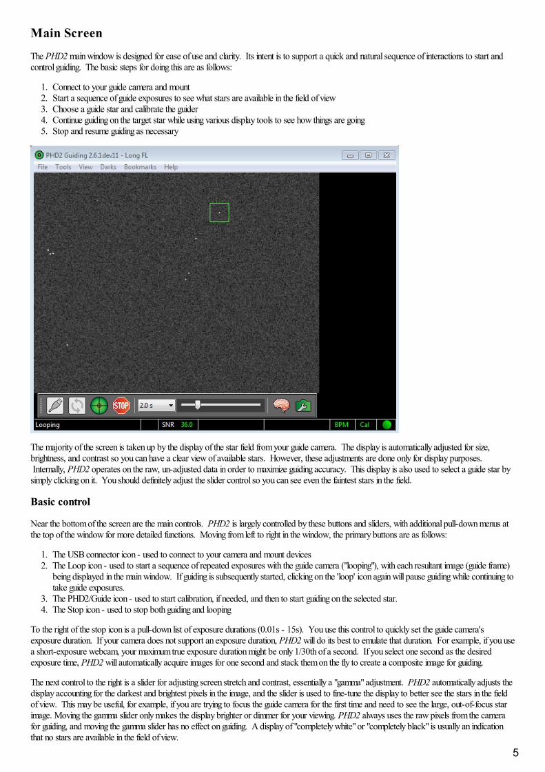
The PHD2 main window is designed for ease of use and clarity. Its intent is to support a quick and natural sequence of interactions to start andcontrol guiding. The basic steps for doing this are as follows:
1. Connect to your guide camera and mount2. Start a sequence of guide exposures to see what stars are available in the field of view3. Choose a guide star and calibrate the guider4. Continue guiding on the target star while using various display tools to see how things are going5. Stop and resume guiding as necessary
The majority of the screen is taken up by the display of the star field from your guide camera. The display is automatically adjusted for size,brightness, and contrast so you can have a clear view of available stars. However, these adjustments are done only for display purposes. Internally, PHD2 operates on the raw, un-adjusted data in order to maximize guiding accuracy. This display is also used to select a guide star bysimply clicking on it. You should definitely adjust the slider control so you can see even the faintest stars in the field.
Basic control
Near the bottom of the screen are the main controls. PHD2 is largely controlled by these buttons and sliders, with additional pull-down menus atthe top of the window for more detailed functions. Moving from left to right in the window, the primary buttons are as follows:
1. The USB connector icon - used to connect to your camera and mount devices2. The Loop icon - used to start a sequence of repeated exposures with the guide camera ("looping"), with each resultant image (guide frame)
being displayed in the main window. If guiding is subsequently started, clicking on the 'loop' icon again will pause guiding while continuing totake guide exposures.
3. The PHD2/Guide icon - used to start calibration, if needed, and then to start guiding on the selected star. 4. The Stop icon - used to stop both guiding and looping
To the right of the stop icon is a pull-down list of exposure durations (0.01s - 15s). You use this control to quickly set the guide camera'sexposure duration. If your camera does not support an exposure duration, PHD2 will do its best to emulate that duration. For example, if you usea short-exposure webcam, your maximum true exposure duration might be only 1/30th of a second. If you select one second as the desiredexposure time, PHD2 will automatically acquire images for one second and stack them on the fly to create a composite image for guiding.
The next control to the right is a slider for adjusting screen stretch and contrast, essentially a "gamma" adjustment. PHD2 automatically adjusts thedisplay accounting for the darkest and brightest pixels in the image, and the slider is used to fine-tune the display to better see the stars in the fieldof view. This may be useful, for example, if you are trying to focus the guide camera for the first time and need to see the large, out-of-focus starimage. Moving the gamma slider only makes the display brighter or dimmer for your viewing. PHD2 always uses the raw pixels from the camerafor guiding, and moving the gamma slider has no effect on guiding. A display of "completely white" or "completely black" is usually an indicationthat no stars are available in the field of view.
5

Next to the gamma slider is the "brain button." This button brings up an Advanced Dialog for making detailed adjustments to PHD2's guidingoperations. An important design goal of the program is to minimize your need to change these parameters, but "the brain" is nothing to be feared -there are adjustments available here that can significantly improve your guiding results and make your life easier. Over a period of time, you shouldtake a look at this dialog and learn what it can do for you.
The rightmost control in this row is a "camera properties" button. Depending on the particular camera, this button may be enabled to provideaccess to a configuration dialog unique to the camera. However, common camera properties such as gain and binning will normally be set in the'Camera' tab of the PHD2 Advanced Dialog. If the button is disabled, any available properties can be set in the PHD2 Advanced Dialog..
Menus
The pull-down menus above the main guider display are used to access a variety of functions. These are described in the Darks, Tools andUtilities, and Visualization sections of this help document.
Status Bar
The status bar at the bottom of the main window is used to display messages and status information that will help you keep track of guidingoperations.
Near the center of the status bar are fields showing the current state of the guide star. If the SNR value drops below 10, its value will be shown inyellow as a warning that you may encounter some 'lost-star' events. If the guide star is saturated, the field to the left of SNR will show 'Saturated'in a red typeface.
To the right of the star status fields are two text fields showing the latest RA and Dec guide commands. These show the size of the guide pulse, thecorrection amount in pixels, and an arrow showing the direction. The arrows follow the usual compass conventions: Dec up/down corresponds tonorth/south, RA left/right corresponds to west/east. All of this information is captured in the log files and displayed in the various graphical tools,and those are what you should use for visualizing your guide performance. But these status fields may give you a quick visual clue when somethingis behaving unusally.
The rightmost panels in the status bar show icons that give you visual clues about the current state of PHD2:. These icons are color-coded to giveyou a dashboard view of current status and have the following meanings:
'Dark' - red means neither a dark library nor a bad-pixel map is being used, green means one or the other is in-use. If you're using a bad-pixelmap, the text will say 'BPM' rather than 'Dark'
'Cal' - shows the state of calibration. Red means the mount is currently uncalibrated, while yellow means there is a calibration but it isn't beingadjusted automatically to account for scope pointing position. This will happen when you aren't using either an ASCOM or 'aux' mount connectionin PHD2. If the icon is yellow, you will generally need to recalibrate when you move the scope to different declination positions.
"The Ball" - shows whether all the equipment in your profile has been successfully connected. If the ball is yellow, some components are notconnected, while green means everything is connected.
If you hover the mouse cursor over any of these status icons, you'll see details about the current state.
6
Using PHD2 Guiding
There are five basic steps to start guiding.
1. Press the USB-icon button and connect to your guide camera and mount.2. Pick an exposure duration from the drop-down list.3. Hit the loop button and look at the available stars, adjusting focus if necessary. Move the mount or adjust the exposure duration as needed
to find a suitable guide star.4. Click on a non-saturated star that's not very near an edge for use as the guide star.5. Press the PHD2 Guide button.
Details of these operations will be described in the sections below.
Equipment ConnectionExposure Time and Star SelectionCalibrationGuiding
Equipment Connection
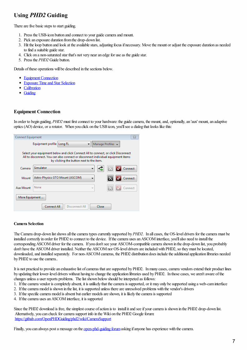
In order to begin guiding, PHD2 must first connect to your hardware: the guide camera, the mount, and, optionally, an 'aux' mount, an adaptiveoptics (AO) device, or a rotator. When you click on the USB icon, you'll see a dialog that looks like this:
Camera Selection
The Camera drop-down list shows all the camera types currently supported by PHD2. In all cases, the OS-level drivers for the camera must beinstalled correctly in order for PHD2 to connect to the device. If the camera uses an ASCOM interface, you'll also need to install thecorresponding ASCOM driver for the camera. If you don't see your ASCOM-compatible camera shown in the drop-down list, you probablydon't have the ASCOM driver installed. Neither the ASCOM nor OS-level drivers are included with PHD2, so they must be located,downloaded, and installed separately. For non-ASCOM cameras, the PHD2 distribution does include the additional application libraries neededby PHD2 to use the camera..
It is not practical to provide an exhaustive list of cameras that are supported by PHD2. In many cases, camera vendors extend their product linesby updating their lower-level drivers without having to change the application libraries used by PHD2. In those cases, we aren't aware of thechanges unless a user reports problems. The list shown below should be interpeted as follows:1. If the camera vendor is completely absent, it is unlikely that the camera is supported, or it may only be supported using a web-cam interface2. If the camera model is shown in the list, it is supported unless there are unresolved problems with the vendor's drivers3. If the specific camera model is absent but earlier models are shown, it is likely the camera is supported4. If the camera uses an ASCOM interface, it is supported
Since the PHD2 download is free, the simplest course of action is to install it and see if your camera is shown in the PHD2 drop-down list. Alternatively, you can check for camera support info in the Wiki on the PHD2 Google forum: https://github.com/OpenPHDGuiding/phd2/wiki/CameraSupport
Finally, you can always post a message on the open-phd-guiding forum asking if anyone has experience with the camera.
7
Baseline list of supported cameras:
Windows:
ASCOM v5/6 compliant camerasAtik 16 series, color or monochromeAtik Gen 3 color or monochromeCCD-Labs Q-GuiderFishcamp StarfishiNova PLC-MMagZero MZ-5Meade DSI series: I-III, color and monochromeOrion StarShoot DSCI Orion Starshoot AutoguiderOrion Starshoot Planetary Imager and AutoguiderQHY 5-IIQHY 5L-IISAC4-2SBIGSBIG rotatorStarlight Xpress SXF / SXVF / LodestarWebcams (LXUSB, parallel, serial, OpenCV, WDM)ZWO ASI
Mac:
Fishcamp StarfishKWIQGuiderMeade DSI series: I-III, color and monochromeOrion Starshoot AutoguiderSBIGStarlight XPress SXVThe Imaging Source (DCAM Firewire)ZWO ASI
Support for SBIG Dual-chip Cameras
Many cameras from the Santa Barbara Instrument Group (SBIG) have two sensors - a primary one for imaging and a second, smaller one forguiding. While the two sensors are physically separate, they share electronics inside the camera and more importantly, share a single USB datalink to the computer. This means that downloading of data from the two sensors must be coordinated - you can't retrieve a guider image while animage from the main sensor is being downloaded. Beyond that, Windows will only allow one application at a time to connect to the camera overthe single USB link. These are physical and architectural restrictions that can't be circumvented by PHD2. However, it is possible for the camera-controlling (image capture) application to implement an interface for PHD2 to get data from the guide chip - essentially, a "side door" mechanismthat won't violate any of the above rules. With this arrangement, the image capture application is acting as a traffic cop to coordinate access to thetwo camera sensors. At the time of this writing (October 2015), the only imaging application that does this is Sequence Generator Pro (SGP). Ifyou use SGP as your main imaging application, you can also use their "SGP API Guider" module, which allows PHD2 to access the guide chip onthe SBIG camera.
ASCOM Camera Properties
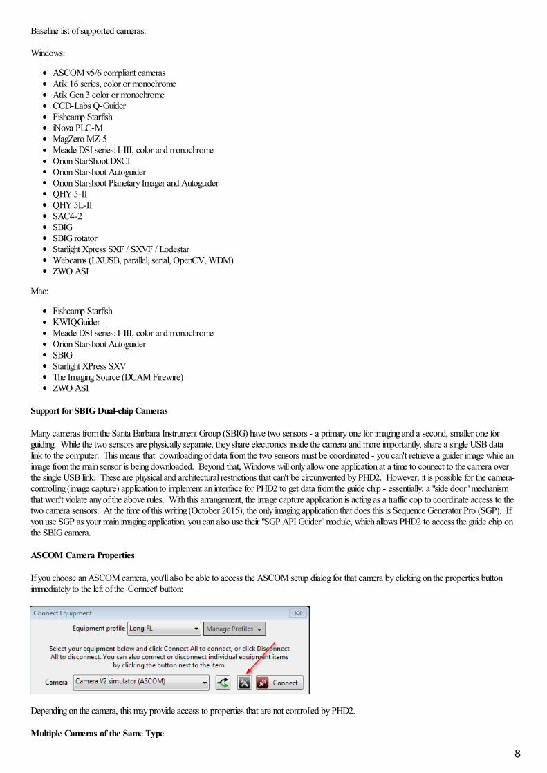
If you choose an ASCOM camera, you'll also be able to access the ASCOM setup dialog for that camera by clicking on the properties buttonimmediately to the left of the 'Connect' button:
Depending on the camera, this may provide access to properties that are not controlled by PHD2.
Multiple Cameras of the Same Type
8
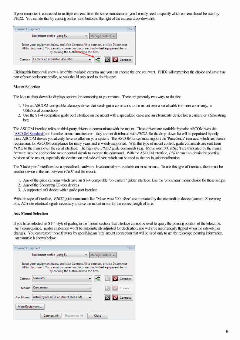
If your computer is connected to multiple cameras from the same manufacturer, you'll usually need to specify which camera should be used byPHD2. You can do that by clicking on the 'fork' button to the right of the camera drop-down list:
Clicking this button will show a list of the available cameras and you can choose the one you want. PHD2 will remember the choice and save it aspart of your equipment profile, so you should only need to do this once.
Mount Selection
The Mount drop-down list displays options for connecting to your mount. There are generally two ways to do this:
1. Use an ASCOM-compatible telescope driver that sends guide commands to the mount over a serial cable (or more commonly, aUSB/Serial connection)
2. Use the ST-4 compatible guide port interface on the mount with a specialized cable and an intermdiate device like a camera or a Shoestringbox
The ASCOM interface relies on third-party drivers to communicate with the mount. These drivers are available from the ASCOM web site(ASCOM Standards) or from the mount manufacturer - they are not distributed with PHD2. So the drop-down list will be populated by onlythose ASCOM drivers you already have installed on your system. The ASCOM driver must support the 'PulseGuide' interface, which has been arequirement for ASCOM compliance for many years and is widely supported. With this type of mount control, guide commands are sent fromPHD2 to the mount over the serial interface. The high-level PHD2 guide commands (e.g. "Move west 500 mSec") are translated by the mountfirmware into the appropriate motor control signals to execute the command. With the ASCOM interface, PHD2 can also obtain the pointingposition of the mount, especially the declination and side-of-pier, which can be used as factors in guider calibration.
The "Guide-port" interfaces use a specialized, hardware-level control port available on most mounts. To use this type of interface, there must beanother device in the link between PHD2 and the mount:
1. Any of the guide cameras which have an ST-4 compatible "on-camera" guider interface. Use the 'on camera' mount choice for these setups.2. Any of the Shoestring GP-xxx devices3. A supported AO device with a guide port interface
With this style of interface, PHD2 guide commands like "Move west 500 mSec" are translated by the intermediate device (camera, Shoestringbox, AO) into electrical signals necessary to drive the mount motor for the correct length of time.
Aux Mount Selection
If you have selected an ST-4 style of guiding in the 'mount' section, that interface cannot be used to query the pointing position of the telescope. As a consequence, guider calibration won't be automatically adjusted for declination, nor will it be automatically flipped when the side-of-pierchanges. You can restore these features by specifying an "aux" mount connection that will be used only to get the telescope pointing information. An example is shown below:
9
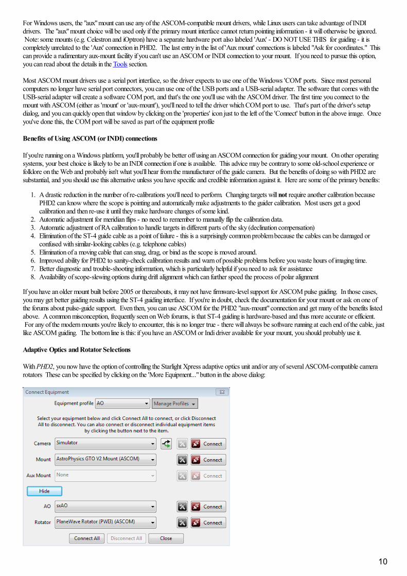
For Windows users, the "aux" mount can use any of the ASCOM-compatible mount drivers, while Linux users can take advantage of INDIdrivers. The "aux" mount choice will be used only if the primary mount interface cannot return pointing information - it will otherwise be ignored. Note: some mounts (e.g. Celestron and iOptron) have a separate hardware port also labeled 'Aux' - DO NOT USE THIS for guiding - it iscompletely unrelated to the 'Aux' connection in PHD2. The last entry in the list of 'Aux mount' connections is labeled "Ask for coordinates." Thiscan provide a rudimentary aux-mount facility if you can't use an ASCOM or INDI connection to your mount. If you need to pursue this option,you can read about the details in the Tools section.
Most ASCOM mount drivers use a serial port interface, so the driver expects to use one of the Windows 'COM' ports. Since most personalcomputers no longer have serial port connectors, you can use one of the USB ports and a USB-serial adapter. The software that comes with theUSB-serial adapter will create a software COM port, and that's the one you'll use with the ASCOM driver. The first time you connect to themount with ASCOM (either as 'mount' or 'aux-mount'), you'll need to tell the driver which COM port to use. That's part of the driver's setupdialog, and you can quickly open that window by clicking on the 'properties' icon just to the left of the 'Connect' button in the above image. Onceyou've done this, the COM port will be saved as part of the equipment profile
Benefits of Using ASCOM (or INDI) connections
If you're running on a Windows platform, you'll probably be better off using an ASCOM connection for guiding your mount. On other operatingsystems, your best choice is likely to be an INDI connection if one is available. This advice may be contrary to some old-school experience orfolklore on the Web and probably isn't what you'll hear from the manufacturer of the guide camera. But the benefits of doing so with PHD2 aresubstantial, and you should use this alternative unless you have specific and credible information against it. Here are some of the primary benefits:
1. A drastic reduction in the number of re-calibrations you'll need to perform. Changing targets will not require another calibration becausePHD2 can know where the scope is pointing and automatically make adjustments to the guider calibration. Most users get a goodcalibration and then re-use it until they make hardware changes of some kind.
2. Automatic adjustment for meridian flips - no need to remember to manually flip the calibration data.3. Automatic adjustment of RA calibration to handle targets in different parts of the sky (declination compensation)4. Elimination of the ST-4 guide cable as a point of failure - this is a surprisingly common problem because the cables can be damaged or
confused with similar-looking cables (e.g. telephone cables)5. Elimination of a moving cable that can snag, drag, or bind as the scope is moved around.6. Improved ability for PHD2 to sanity-check calibration results and warn of possible problems before you waste hours of imaging time.7. Better diagnostic and trouble-shooting information, which is particularly helpful if you need to ask for assistance8. Availability of scope-slewing options during drift alignment which can further speed the process of polar alignment
If you have an older mount built before 2005 or thereabouts, it may not have firmware-level support for ASCOM pulse guiding. In those cases,you may get better guiding results using the ST-4 guiding interface. If you're in doubt, check the documentation for your mount or ask on one ofthe forums about pulse-guide support. Even then, you can use ASCOM for the PHD2 "aux-mount" connection and get many of the benefits listedabove. A common misconception, frequently seen on Web forums, is that ST-4 guiding is hardware-based and thus more accurate or efficient. For any of the modern mounts you're likely to encounter, this is no longer true - there will always be software running at each end of the cable, justlike ASCOM guiding. The bottom line is this: if you have an ASCOM or Indi driver available for your mount, you should probably use it.
Adaptive Optics and Rotator Selections
With PHD2, you now have the option of controlling the Starlight Xpress adaptive optics unit and/or any of several ASCOM-compatible camerarotators These can be specified by clicking on the 'More Equipment..." button in the above dialog:
10
If you don't have these devices, just leave the selections at 'None.' If these devices are connected, you'll see additional tabs in the 'AdvancedSettings' dialog that provide access to various device-related properties. PHD2 does not control a rotator, but it will read the current angle settingfrom the rotator and adjust the guiding calibration if needed.
Simulators
All of the PHD2 devices - camera, mount, AO, rotator - include built-in simulators. Don't confuse these with any of the ASCOM simulatorswhich may be installed on your system - those will have 'ASCOM' in their names. Although you can connect to the ASCOM simulators, theydon't provide the necessary feedback to PHD2 for guiding and calibration. As a result, they're only useful for limited types of testing andexperimentation. But you can use the built-in simulators to explore how PHD2 works and to decide how you want to use the program. There'sno reason to waste valuable dark-sky time learning to use PHD2! Virtually all of PHD2's features, including full calibration and all the graphicaldisplay options, will work properly when the built-in device simulators are used. You'll even see fairly realistic guiding performance to give yousome idea of what to expect in the field. To get started using the simulators, choose 'Simulator' for the camera type and 'On-camera' for theMount type.
That said, the simulators are not useful for trouble-shooting any problems you encounter with your real mount. Both the camera and the mountmust be real devices in order to diagnose problems or otherwise get your gear calibrated and working. In that sense, what you see when using thesimulators is realistic but "fake" behavior. The simulators can be useful in some cases for reproducing PHD2 application problems, but not foranything having to do with your actual guiding equipment.
Equipment Profiles
At the top of the 'Connect Equipment' dialog are some additional controls for managing equipment profiles. All of the guider settings in PHD2,default or otherwise, are automatically stored as part of an equipment profile. If you have only one guiding setup - you use the same camera andguide scope combination each time - you will only need one profile; and you can just use the default profile. But you may have multiple equipmentconfigurations - for example, an off-axis-guiding arrangement for a long focal length scope and a separate guide scope/camera configuration for ashorter focal length imaging scope. The PHD2 guide settings for those configurations are likely to be different, so you would want to use separateequipment profiles The controls at the top of the 'Connect Equipment' dialog let you choose the profile you want to use and to create/edit/removeprofiles as you see fit. When you select a profile and connect to its associated equipment, all of the settings last used with that profile areautomatically reloaded. Once you've established the profiles you need - perhaps only the default one - you can simply click on the 'Connect All'button and you're ready to move ahead. If you already have a suitable default equipment profile and you simply want to connect to theequipment just as before, you can do a <shift>-click on the main screen 'USB' button and PHD2 will automatically re-connect to your hardware.
New-Profile-Wizard
The best way to create a new profile is to use the "Wizard" capability. The wizard takes you through a sequence of windows that explain thevarious settings and help you decide how to set them. It will also calculate baseline algorithm settings that are likely to work reasonably well foryour set-up. Creating a profile this way is faster and less error-prone than doing it by hand in the 'Connect Equipment' dialog. When you runPHD2 for the first time on your system, this wizard will be automatically launched. Subsequently, you can use the new-profile wizard by clickingon the 'Manage Profiles' field in the 'Connect Equipment' dialog, then choosing 'New using wizard...'.
The wizard asks a number of questions that are important for getting your profile built correctly. The explanatory text in each pane of the wizardshould make clear what is being asked and what needs to be done. But here are some additional tips to help you through the process:
1. Connection Options: As you make selections for the various devices, you will usually see a prompt asking if the device is alreadyconnected and ready to communicate with PHD2. If you say 'yes', PHD2 will try to connect and then fill in some of the data fields withinformation read from the device. Saying 'no' simply means you'll have to enter the data by hand. If PHD2 tries to connect with the deviceand fails, you'll still be able to proceed by just entering the data manually. Device-connection in the wizard is basically a conveniencefeature that makes it easier to fill in the fields with accurate values. You won't see the prompt if PHD2 already knows the device can't returnuseful information - for example, if the mount choice is 'on-camera.'2. Camera connection pane: unbinned pixel size. If you said 'yes' to the connection prompt, this information will usually be filled inautomatically and the control will be disabled. If you said 'no' or if the device doesn't report its pixel-size, you'll need to enter the value byhand. You should be able to get the unbinned pixel size from the camera spec sheet or the manufacturer's web site. If the pixels aren'tsquare, just specify the larger dimension or the average value if you prefer. This won't have any effect on your actual guidng results, but itwill allow PHD2 to know the image-scale for your set-up. This is used for setting baseline guiding parameters, doing sanity-checks oncalibrations, and reporting guiding performance.3. Camera connection pane: binning level. If your guide camera supports binning (many do not), you can specify what level of binningyou want to use for this equipment profile. If you want to use the same equipment set-up with different binning levels, it's best to createseparate profiles for each binning value. 4. Camera connection pane: guide scope focal length. This seems to be a common place for mistakes, so it's worth being careful andgetting it right. The correct value is not the aperture of the guide scope, it is the focal length. So, for example, if you're guiding with a50mm finder scope, the focal length willl not be 50mm - it will probably be something closer to 150-175mm. A 60-80mm refractor guidescope will probably have a focal length in the range of 240-500mm, not 60-80mm. Similarly, if you're guidng with an OAG on your mainimaging scope, the focal length will be that of the main scope. In some cases, you may be using a small threaded focal reducer on the guidecamera, so that must also be taken into account. Like the pixel-size entry, the focal length doesn't demand a great deal of precision, but you
11
should get as close as you can. Otherwise, the performance numbers may not reflect your actual results and the baseline guiding parametersmay be sub-optimal.5. Mount connection pane: mount guide speed. This is another area that seems to cause confusion. The guide speed is a parameterset in the mount or in the mount driver, it's not something controlled by PHD2. PHD2 never sets the mount guide speed, it only reads it. It is usually expressed as a multiple of the sidereal rate and is typically in the range of 0.5x - 1x sidereal. Despite what you may readelsewhere, it's generally best to use guide speeds in this range rather than much lower speeds. Higher guide speeds can help to clearbacklash more quickly and may help to overcome stiction problems. If you say 'yes' to the connection option prompt, PHD2 will attempt toread the current guide speed from the mount. If this fails for some reason, you'll need to enter the guide speed manually. PHD2 uses thisvalue to automatically set the calibration step-size and to aid in checking calibration results; but the guide speed information is not importantfor the actual guiding. If you're using different guide speeds on the RA and Dec axes, enter the larger value. If you really can't determinewhat the guide speed settings are in the mount, leave the setting at the default value of 0.5X.
In the last pane of the wizard dialog, you're given the option to build a dark library for the profile, You should always do this unless you alreadyhave a compatible dark library that you're going to import from a different profile. If you are changing cameras and want to keep the dark librariesand bad-pixel maps associated with the old camera, you should create a separate profile for the new camera. When a camera selection is changedin an existing profile, the previously built dark library and bad-pixel map data will no longer be usable. That also applies to using the same camerawith different binning values. Setups using different binning factors should be kept in separate profiles because the dark library and bad-pixel mapsdepend on the binning factor.
Exposure Time and Star Selection
The guide star can be selected (clicked on) while "looping" is active - in fact, this is the recommended method. It can also be selected after loopinghas been stopped, but this opens the possibility that the star might have moved since the last exposure. No great precision is required in clickingon the star - PHD2 will find the star nearest to the cursor. After you do this, a green box will appear to frame the star. If you pick a star that istoo bright (saturated), the status bar will show a red 'SAT' label and you should choose a fainter star. You should adjust the gamma slider to theleft to see fainter stars. Most new users are fooled by this and often choose the brightest star they happen to see in the field of view. But thatchoice is often a saturated star, not a good choice for auto-guiding. The choice of exposure time will depend entirely on your equipment, skyconditions, and the available stars. The exposure time you choose has several implications:
1. It affects the signal strength (brightness) of the selected star - a brighter star will stand out better from the background and will generallyproduce better guiding results so long as it is not saturated.
2. It also determines the frequency with which guide commands are sent to the mount - guide commands cannot be sent any more frequentlythan once for each exposure cycle. Some mounts need frequent small guiding adjustments while others do not - you may need toexperiment to understand what works best for your situation.
3. It has a strong effect on the sensitivity of the guide algorithms to seeing conditions. As the exposure time is increased up through 2-4seconds, the effects of seeing are smoothed out. The camera is essentially averaging out the larger, high-frequency seeing movements, sothe guide algorithms have less difficulty distinguishing "seeing jitter" from actual guide star displacements that need to be corrected. This isparticularly noticeable if you are guiding with a long focal length setup. Of course, the convenience of using longer exposures must be tradedoff against the need for the mount to get frequent corrections.
As a starting point, try using exposure durations in the range of two to three seconds. Rather than choosing the star yourself with a mouse-click,it's better to let PHD2 Auto-select the guide star by using the Alt-S keyboard shortcut after stars are visible in the main display. If you want to de-select a star without choosing another one, you can do a shift-click anywhere on the image display window. If you are just starting with thisequipment set-up, you'll probably need to focus the guide camera - doing so is important for good guiding. You can use the Star Profile tool tohelp with that process. If you're using a small guide scope, like a finder-scope, the focus may react strongly to small adjustments. It's important tospend the time to get a good focus because a poorly focused guide star can lead to many other problems. The camera exposure control displays awide range of pre-set exposure times. Exposure times smaller than one second are intended for use with adaptive optics devices or in otherspecial situations - they are generally not appropriate for use with typical guide camera set-ups. There is also a 'custom' exposure option at thebottom of the list that lets you specify a value not already displayed. Again, this is intended for special applications, for example where anunusually long exposure time is needed.
There is also an Auto exposure time selection available. When exposure is set to Auto, PHD2 will attempt to adjust the exposure to keep theselected guide star at a constant signal-to-noise ratio (SNR) value. This is a specialized measurement used by PHD2 to determine how well thestar can be distinguished from the background - it is similar but not identical to the signal-to-noise ratio used in photometry. The Auto setting isprimarily intended for AO users who want to minimize exposure time without losing the guide star. The settings to control Auto-exposure are onthe Camera Tab of the Advanced Dialog. Non-AO users should probably not use the "Auto' exposure setting because itcomplicates interpretation of the guiding results.
Automatic Calibration
Conventional Mounts
Two things need to be measured by PHD2 as part of guider calibration:
12
1. The angle of the camera relative to the telescope axes 2. The length of the guide pulse needed to move the telescope by a specific amount
PHD2 handles these measurements automatically by sending guide pulses to the mount and watching how far and in which direction the star movesbetween guide camera images. This process begins after you have selected a star and then clicked on the PHD2/Guide icon button. Yellowcross-hairs will appear over the original location of your guide star and PHD2 will start to move the mount in various directions, tracking how thestar moves as a function of what move commands were sent to the mount. The status bar will display the commands as they are sent to the mount,along with the incremental movements of the guide star relative to its starting position. PHD2 will do this on both axes, first moving east and west,then north and south. PHD2 wants to move the star up to 25 pixels in each direction in order to get an accurate calibration. Once this iscomplete, the crosshairs will turn green and guiding will start automatically.
Although PHD2 moves the guide star in all four directions, only the west and north movements are actually used to compute the guide rates andcamera angle. The east and south moves are used only to restore the star roughly to its starting position. Before the north moves are begun, youwill see a sequence of pulses that are intended to clear backlash. PHD2 takes a fairly aggressive approach to clearing this backlash, watching for aclear pattern of movement in a single direction with no reversals. Even so, these pulses may still not clear all the declination backlash in yourmount, particularly if you are significantly affected by seeing conditions. In that case, the computed declination rate may be too low, a situationthat is discussed further in the Tools and Utilities section. You may also see that the south pulses leave the guide star well-short of its startingposition - this is another visual clue that you have significant declination backlash in your mount. If you see evidence of sizable backlash, you canrun the Guiding Assistant tool and measure it directly.
In most cases, calibration will complete automatically without any user involvement. If you get frequent failures during calibration, you shouldconsult the trouble-shooting section.
If you're using an ASCOM (or Indi) connection for either the 'mount' or 'aux-mount', a good calibration can be re-used for a long time, and that isthe preferred way to operate. These connection options allow PHD2 to know where the telescope is pointing, so a calibration done at one pointin the sky will be automatically adjusted as you slew to different targets. The old method of having to re-calibrate whenever you slewed the scopeor switched the side-of-pier is a thing of the past so long as PHD2 has pointing information. With this type of set-up, you would only re-calibrate ifyou rotate the position of the guide camera by more than about 5 degrees or make other major changes to the hardware configuration. In general,the best practice is to get a good calibration within about +/- 20 degrees of the celestrial equator and high enough in the sky to avoid major seeing(turbulence) problems. Since PHD2 has pointing information for this type of configuration, the 'Auto restore calibration' option in the Guiding tabof the Advanced Dialog will be checked automatically. From this point forward, you can simply connect to your gear, choose a guide star, thenbegin guiding immediately. Finally, if you're using an instrument rotator as part of your equipment profile, PHD2 can use the 'Rotator' connectionto adjust the calibration data based on the angular position of the guide camera - one less reason for re-doing a calibration.
You can always review the results of your last calibration by using the 'Tools' menu and clicking on 'Review Calibration Data' That will open adialog that shows a graphical representation of the mount's movements along with the values that were computed for guiding your mount. Thiswindow is described elsewhere in the Calibration Details section of the help file. As a quick quality check, you can open this window and confirmthat 1) the RA and Dec lines are roughly perpendicular and 2) the plotted points are roughly linear with no significant curves, bends, clumping ofpoints, or reversals in direction. If you do see these kinds of odd patterns in the graph, you should probably re-do the calibration. Even withhigh-end mounts, calibrations can occasionally go awry because of environmental conditions, especially wind and bad seeing.
After a calibration is completed, PHD2 will "sanity check" the results to be sure the calculations at least look reasonable. If they don't, you will seean 'alert' message at the top of the main window that describes the calibration result that looks questionable. You can choose to ignore the alert orclick on 'Details' to get more information. It is generally advisable to pay attention to these alerts because there is no point in trying to guide using asignificantly bad calibration.
Adaptive Optics Devices
If you are using an adaptive optics device, there are actually two calibration processes that must complete. The first handles calibration of thetip/tilt mirror in the AO and calculates the magnitude and direction of the adjustments as they relate to displacements of the guide star. The secondcalibration is the one described above, dealing with guide commands that need to be sent to the mount. Known as "bump" commands, these willbe issued when the guide star has moved beyond the range of corrections that can be achieved with the AO alone.
Guiding
Once guiding has begun, diagnostic messages will be displayed in the status bar to show what guide commanda are being sent to the mount. PHD2will continue guiding until you click on the 'Stop' icon. To resume guiding, simply start looping exposures again, select your star, and click on the'Guide' button. You will not need to repeat the calibration in order to resume guiding. In some cases, PHD2 may lose the guide star and you'll bealerted by an audible beep and flashing orange crosshairs. There are several reasons this might occur:
1. Something may be obscuring the star - clouds, the observatory roof, a tree, etc.2. The star may have abruptly moved out of the tracking rectangle because something shifted in the mount/camera/cabling infrastructure -
cable snags can cause this3. The star may have "faded" for some other reason, perhaps because it is overly faint or the camera is not well-focused
13
Obviously, you'll need to identify the source of the problem and fix it. However, it's important to understand that PHD2 will not start moving thetelescope around in an attempt to relocate the guide star. It will simply continue to take exposures and look for the guide star to reappear withinthe bounds of the current tracking rectangle. When you first start guiding, you may see an 'alert' dialog at the top of the window if no dark libraryor bad-pixel map is being used. You can choose to ignore this warning and continue with guiding, but you are likely to get better results if youspend the few minutes needed to construct a dark library for future use.
If you are using a German equatorial mount (GEM), you will usually have to do a "meridian flip" around the time your image target crosses themeridian. This means you will move the telescope around to the opposite side of the pier and then resume imaging. Doing this invalidates theoriginal calibration, typically because the declination directions are now reversed. If you are using an ASCOM (or 'aux' ) mount interface, yourcalibration will be adjusted automatically and you can simply resume guiding (assuming you haven't also rotated the camera or focuser). If youaren't using an interface that returns pointing position, you will need to take action to adjust the guider calibration. You can, of course, simply doanother calibration on the current side of the pier, a process that will typically take only a couple of minutes. Or, you can use the pull-down menuitem under 'Tools/Modify Calibration' to "flip calibration data" and then resume guiding immediately. Note: 'flip calibration data' will have no effectif PHD2 is using an ASCOM or 'aux-mount' connection.
In some cases, you may want to force a re-calibration. For example, you may have rotated the guide camera as part of resolving a cable problem. You can do this by clicking on the 'Brain button', moving to the 'Guiding' tab, and clicking the 'Clear mount calibration' checkbox. Or, you cansimply do a <shift>click on the 'Guide' button on the main screen and PHD2 will start a calibration run.
Once you have started guiding, you will almost certainly want to know how things are going. You can of course watch the star in the guide cameradisplay but in many cases you won't be able to see all the small adjustments that are taking place. But PHD2 provides many tools for measuringand displaying your performance, as described in the Visualization section. Several of the guiding algorithms have limit settings for the maximumguide correction that can be issued with a single command. If these values are smaller than what is needed to correct the mount's position, you willsee an alert dialog at the top of the main window advising you of the situation. If this is a recurring problem, you may want to increase the valuesfor these settings or otherwise solve the underlying problem.
14
Dark Frames and Bad-pixel Maps
Introduction
Cameras used for guiding are typically not temperature-regulated and may produce images that appear quite noisy. As a result, guide exposuresfrequently show obvious defects in the form of hot ("stuck") pixels or regions with spurious brightness levels. If there are too many of thesedefects, you may have trouble identifying and selecting a good guide star - trying to calibrate on a hot pixel is a common problem for beginners. Even after guiding has begun, a spurious hot pixel close to the guide star can disrupt the calculations needed for smooth guiding and may cause thesoftware to "jump" between the real star and the hot pixel. These sorts of problems can be mitigated by using either of two approaches in PHD2:dark frames and bad pixel maps. All functions related to dark frames and bad-pixel maps are located under the top-level 'Darks' menu.
Dark Frames
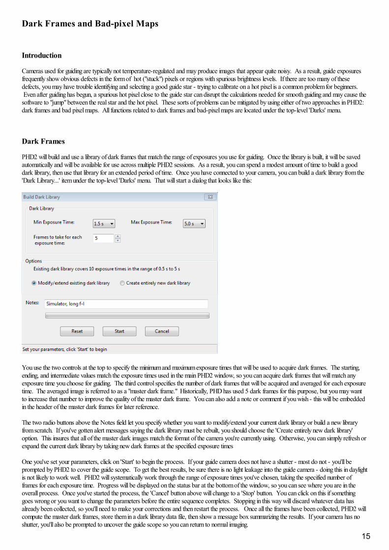
PHD2 will build and use a library of dark frames that match the range of exposures you use for guiding. Once the library is built, it will be savedautomatically and will be available for use across multiple PHD2 sessions. As a result, you can spend a modest amount of time to build a gooddark library, then use that library for an extended period of time. Once you have connected to your camera, you can build a dark library from the'Dark Library...' item under the top-level 'Darks' menu. That will start a dialog that looks like this:
You use the two controls at the top to specify the minimum and maximum exposure times that will be used to acquire dark frames. The starting,ending, and intermediate values match the exposure times used in the main PHD2 window, so you can acquire dark frames that will match anyexposure time you choose for guiding. The third control specifies the number of dark frames that will be acquired and averaged for each exposuretime. The averaged image is referred to as a "master dark frame." Historically, PHD has used 5 dark frames for this purpose, but you may wantto increase that number to improve the quality of the master dark frame. You can also add a note or comment if you wish - this will be embeddedin the header of the master dark frames for later reference.
The two radio buttons above the Notes field let you specify whether you want to modify/extend your current dark library or build a new libraryfrom scratch. If you've gotten alert messages saying the dark library must be rebuilt, you should choose the 'Create entirely new dark library'option. This insures that all of the master dark images match the format of the camera you're currently using. Otherwise, you can simply refresh orexpand the current dark library by taking new dark frames at the specified exposure times
One you've set your parameters, click on 'Start' to begin the process. If your guide camera does not have a shutter - most do not - you'll beprompted by PHD2 to cover the guide scope. To get the best results, be sure there is no light leakage into the guide camera - doing this in daylightis not likely to work well. PHD2 will systematically work through the range of exposure times you've chosen, taking the specified number offrames for each exposure time. Progress will be displayed on the status bar at the bottom of the window, so you can see where you are in theoverall process. Once you've started the process, the 'Cancel' button above will change to a 'Stop' button. You can click on this if somethinggoes wrong or you want to change the parameters before the entire sequence completes. Stopping in this way will discard whatever data hasalready been collected, so you'll need to make your corrections and then restart the process. Once all the frames have been collected, PHD2 willcompute the master dark frames, store them in a dark library data file, then show a message box summarizing the results. If your camera has noshutter, you'll also be prompted to uncover the guide scope so you can return to normal imaging.
15

Once your dark library has been built, you control its use by the 'Use Dark Library' item under the 'Darks' menu. The checkbox on the menu itemwill toggle on or off each time you click on it. The setting of the item is retained across program executions, so if you choose to leave the menuitem checked, PHD2 will automatically load the dark library and resume its use the next time you run the application. The dark library itself isretained on disk until you build a new library, so you can freely change the setting on the 'Use Dark Library' menu item without loss of any data. Ifyou are using a dark library and there is no master dark frame that exactly matches your guide exposure time, PHD2 will use the nearest fit. However, you are encouraged to obtain matching master dark frames for best results. If you have a dark library that has missing exposure times,you can simply acquire the missing data and it will be added to the existing dark library - there is no need to start over. By changing the setting ofthe 'Use Dark Library' menu item, you'll be able to see the effect of using the dark library and determine whether your guider images are sufficientlyimproved.
Remember that a dark library is associated with a particular camera. PHD2 will check to be sure that the dark library matches the camera you arecurrently using. If it does not, you will see an alert message telling you the dark library can't be used and must be rebuilt. This can happen whenyou've changed cameras inside an existing equipment profile, something you shouldn't do unless you have upgraded your guide camera and haveno plan to revert to use of the old camera.
Bad-pixel Maps (Defect Maps)
For some guide cameras, dark frames don't do an adequate job of removing the defective pixels that are visible in the guide frame. In thosesituations, you can probably get better results by building and using a bad-pixel map. This approach directly measures and compensates forspecific areas of the sensor that produce false signal (hot/stuck pixels) or don't respond correctly to incoming light (cold pixels). Such a "map" iscreated by taking a sequence of comparatively long dark exposures (e.g. 15 seconds), averaging them, then statistically analyzing the resultantframe to identify the locations of defective pixels. These pixel locations are saved for future use. During normal guiding, each of these pixellocations on the guide image is replaced by a statistical sample of the surrounding pixels, thus eliminating all or most of the effect of the "bad" pixel. The final result is usually an image with a smoother background and fewer obvious defects. For any defects that remain, PHD2 also provides away for you to manually click on bad pixel locations and add them to the map. This entire process of obtaining and analyzing dark frames ishandled for you by PHD2, so it's easy to build a bad-pixel map.
Building a bad-pixel map is done by clicking on the 'Bad Pixel Map...' item under the top-level 'Darks' menu. If you are doing this for the firsttime, you will be prompted to obtain a sequence of dark frames for analyzing your camera sensor and building the map:
This is a slightly different version of the dialog used for obtaining dark frames, described in the previous section. Because the analysis is based onstatistics, you should use relatively long exposure times (> 10 sec) and at least 10 frames. Since the bad-pixel map can be re-used for fairly longtime periods, you won't have to repeat this operation very often, and it's worth spending some time to get higher quality data.
Once the dark frames have been captured, PHD2 will compute the statistics and identify an initial set of defective or suspect pixel locations. Aftera short delay, you'll then see a dialog that looks something like this:
16
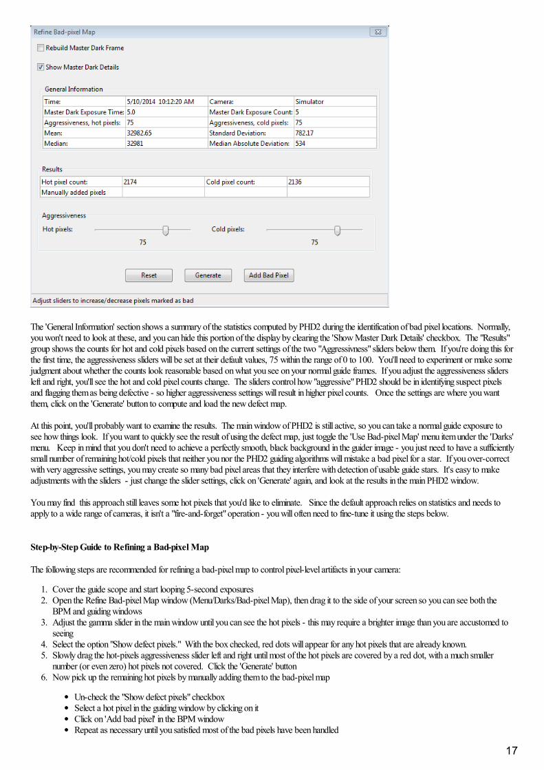
The 'General Information' section shows a summary of the statistics computed by PHD2 during the identification of bad pixel locations. Normally,you won't need to look at these, and you can hide this portion of the display by clearing the 'Show Master Dark Details' checkbox. The "Results"group shows the counts for hot and cold pixels based on the current settings of the two "Aggressivness" sliders below them. If you're doing this forthe first time, the aggressiveness sliders will be set at their default values, 75 within the range of 0 to 100. You'll need to experiment or make somejudgment about whether the counts look reasonable based on what you see on your normal guide frames. If you adjust the aggressiveness slidersleft and right, you'll see the hot and cold pixel counts change. The sliders control how "aggressive" PHD2 should be in identifying suspect pixelsand flagging them as being defective - so higher aggressiveness settings will result in higher pixel counts. Once the settings are where you wantthem, click on the 'Generate' button to compute and load the new defect map.
At this point, you'll probably want to examine the results. The main window of PHD2 is still active, so you can take a normal guide exposure tosee how things look. If you want to quickly see the result of using the defect map, just toggle the 'Use Bad-pixel Map' menu item under the 'Darks'menu. Keep in mind that you don't need to achieve a perfectly smooth, black background in the guider image - you just need to have a sufficientlysmall number of remaining hot/cold pixels that neither you nor the PHD2 guiding algorithms will mistake a bad pixel for a star. If you over-correctwith very aggressive settings, you may create so many bad pixel areas that they interfere with detection of usable guide stars. It's easy to makeadjustments with the sliders - just change the slider settings, click on 'Generate' again, and look at the results in the main PHD2 window.
You may find this approach still leaves some hot pixels that you'd like to eliminate. Since the default approach relies on statistics and needs toapply to a wide range of cameras, it isn't a "fire-and-forget" operation - you will often need to fine-tune it using the steps below.
Step-by-Step Guide to Refining a Bad-pixel Map
The following steps are recommended for refining a bad-pixel map to control pixel-level artifacts in your camera:
1. Cover the guide scope and start looping 5-second exposures2. Open the Refine Bad-pixel Map window (Menu/Darks/Bad-pixel Map), then drag it to the side of your screen so you can see both the
BPM and guiding windows3. Adjust the gamma slider in the main window until you can see the hot pixels - this may require a brighter image than you are accustomed to
seeing4. Select the option "Show defect pixels." With the box checked, red dots will appear for any hot pixels that are already known. 5. Slowly drag the hot-pixels aggressiveness slider left and right until most of the hot pixels are covered by a red dot, with a much smaller
number (or even zero) hot pixels not covered. Click the 'Generate' button6. Now pick up the remaining hot pixels by manually adding them to the bad-pixel map
Un-check the "Show defect pixels" checkboxSelect a hot pixel in the guiding window by clicking on itClick on 'Add bad pixel' in the BPM windowRepeat as necessary until you satisfied most of the bad pixels have been handled
17
Close the BPM window - DO NOT click 'Generate' again because that will undo the manual pixel selection
Once your bad-pixel map has been built, you control its use by the 'Use Bad-pixel Map' item under the 'Darks' menu. This setting is retainedacross program executions, so leaving it checked will tell PHD2 to automatically load the defect map and use it for all guide exposures. Thesettings for 'Use Dark Library' and 'Use Bad-pixel Map' are mutually exclusive - you can use one or neither, but not both at the same time. Aswith the dark library, the bad-pixel map data file is stored permanently, so you can disable its use without losing any data. Both of these datastructures can be used for extended time periods, but it's worth remembering that camera sensors do change over time. As a result, you may wantto rebuild the dark library or bad-pixel maps at periodic intervals or when you start to see a degradation in the appearance of your normal guideimages. In these cases, it is also advisable to click on the checkbox for 'Rebuild Master Dark Frame', which will tell PHD2 to reacquire theunderlying dark frames and recompute a baseline bad-pixel map. You'll then need to refine the map as you did before until you're happy with theresults. There is no reason you should need to interact with either the dark libarary or bad-pixel map data files, but you can find them located inthe 'AppData\Local' logical directory used by your operating system.
Like dark libraries, bad-pixel maps are associated with a particular camera. PHD2 will check to be sure that the bad-pixel map matches thecamera you are currently using. If it does not, you will see an alert message telling you the bad-pixel map can't be used and must be rebuilt. Thiscan happen when you've changed cameras or binning factors inside an existing equipment profile, something you shouldn't do unless you have noneed for the old settings.
Reusing Dark Frames and Bad-pixel Maps
If you're using the same camera in multiple profiles, you may want to re-use the dark libraries or bad-pixel maps you built for that camera. Thiscan be accomplished by importing the camera-related data files into a profile that doesn't already have those files. For example, suppose you builtan original profile - call it Profile1 - that uses your Lodestar guide camera, and you built both a dark library and bad-pixel map for it. Some timelater, you create a new profile, Profile2, that has different mount or focal length properties but still uses the original Lodestar camera. In that case,you would connect your gear using Profile2, then use the 'Import From Profile...' menu item under the top-level 'Darks' menu. You would selectProfile1 as the source of the import function for the dark library, bad-pixel map, or both. You will be shown only those profiles that have a camerawith compatible sensor geometry (size and pixel size). Clicking on 'Ok' will copy the dark/bad-pixel map files and will associated them with yournew profile, Profile2. Since they are copies, changing the data files in one profile will not affect other profiles. Keeping them synchronized, if thatis what you want to do, will require a subsequent 'import' operation.
18
Visualization Tools
PHD2 provides numerous visualization and display tools to help you see how your guider is performing. All of these tools are accessed under the 'View' pull-down menu and aredescribed below.
OverlaysGraphical DisplayStats DisplayStar Profile and Target DisplaysAO GraphDockable Windows
Overlays
The simplest display tools are grid overlays superimposed over the main guider display window. These are quite straightforward and include the following choices:
Bullseye targetFine gridCoarse gridRA/Dec - this shows how the telescope axes are aligned relative to the axes of the camera sensorSpectrograph slit/slit position - for spectroscopy users, this will overlay a spectrograph slit graphic on the main display window. The size, position, and angle of the graphic canbe adusted to match the optical configuration.None
You can just click on the various overlay options under the 'View' menu and choose one that suits you.
Graphical Display
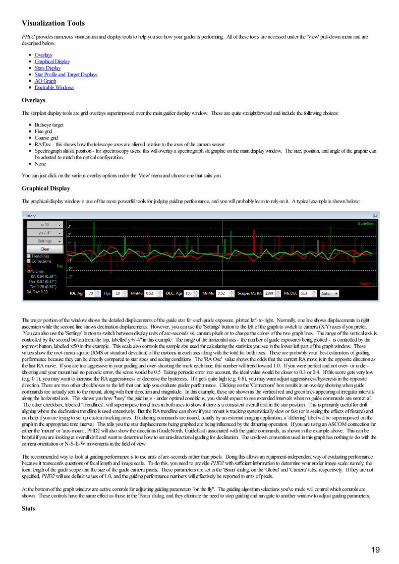
The graphical display window is one of the more powerful tools for judging guiding performance, and you will probably learn to rely on it. A typical example is shown below:
The major portion of the window shows the detailed displacements of the guide star for each guide exposure, plotted left-to-right. Normally, one line shows displacements in rightascension while the second line shows declination displacements. However, you can use the 'Settings' button to the left of the graph to switch to camera (X/Y) axes if you prefer. You can also use the 'Settings' button to switch between display units of arc-seconds vs. camera pixels or to change the colors of the two graph lines. The range of the vertical axis iscontrolled by the second button from the top, labelled y:+/-4" in this example. The range of the horizontal axis - the number of guide exposures being plotted - is controlled by thetopmost button, labelled x:50 in this example. This scale also controls the sample size used for calculating the statistics you see in the lower left part of the graph window. Thesevalues show the root-mean-square (RMS or standard deviation) of the motions in each axis along with the total for both axes. These are probably your best estimators of guidingperformance because they can be directly compared to star sizes and seeing conditions. The 'RA Osc' value shows the odds that the current RA move is in the opposite direction asthe last RA move. If you are too aggressive in your guiding and over-shooting the mark each time, this number will trend toward 1.0. If you were perfect and not over- or under-shooting and your mount had no periodic error, the score would be 0.5 Taking periodic error into account, the ideal value would be closer to 0.3 or 0.4. If this score gets very low(e.g. 0.1), you may want to increase the RA aggressivness or decrease the hysteresis. If it gets quite high (e.g. 0.8), you may want adjust aggressivness/hysteresis in the oppositedirection. There are two other checkboxes to the left that can help you evaluate guider performance. Clicking on the 'Corrections' box results in an overlay showing when guidecommands are actually sent to the mount, along with their direction and magnitude. In this example, these are shown as the vertical red and green lines appearing at irregular intervalsalong the horizontal axis. This shows you how "busy" the guiding is - under optimal conditions, you should expect to see extended intervals when no guide commands are sent at all. The other checkbox, labelled 'Trendlines', will superimpose trend lines in both axes to show if there is a consistent overall drift in the star position. This is primarily useful for driftaligning where the declination trendline is used extensively. But the RA trendline can show if your mount is tracking systematically slow or fast (or is seeing the effects of flexure) andcan help if you are trying to set up custom tracking rates. If dithering commands are issued, usually by an external imaging application, a 'dithering' label will be superimposed on thegraph in the appropriate time interval. This tells you the star displacements being graphed are being influenced by the dithering operation. If you are using an ASCOM connection foreither the 'mount' or 'aux-mount', PHD2 will also show the directions (GuideNorth, GuideEast) associated with the guide commands, as shown in the example above. This can behelpful if you are looking at overall drift and want to determine how to set uni-directional guiding for declination. The up/down convention used in this graph has nothing to do with thecamera orientation or N-S-E-W movements in the field of view.
The recommended way to look at guiding performance is to use units of arc-seconds rather than pixels. Doing this allows an equipment-independent way of evaluating performancebecause it transcends questions of focal length and image scale. To do this, you need to provide PHD2 with sufficient information to determine your guider image scale: namely, thefocal length of the guide scope and the size of the guide camera pixels. These parameters are set in the 'Brain' dialog, on the 'Global' and 'Camera' tabs, respectively. If they are notspecified, PHD2 will use default values of 1.0, and the guiding performance numbers will effectively be reported in units of pixels.
At the bottom of the graph window are active controls for adjusting guiding parameters "on the fly". The guiding algorithm selections you've made will control which controls areshown. These controls have the same effect as those in the 'Brain' dialog, and they eliminate the need to stop guiding and navigate to another window to adjust guiding parameters.
Stats
19
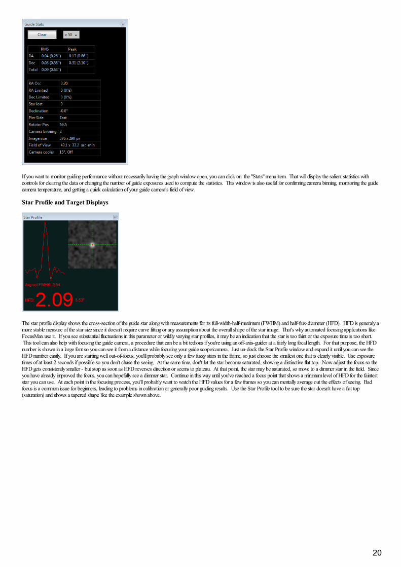
If you want to monitor guiding performance without necessarily having the graph window open, you can click on the "Stats" menu item. That will display the salient statistics withcontrols for clearing the data or changing the number of guide exposures used to compute the statistics. This window is also useful for confirming camera binning, monitoring the guidecamera temperature, and getting a quick calculation of your guide camera's field of view.
Star Profile and Target Displays
The star profile display shows the cross-section of the guide star along with measurements for its full-width-half-maximum (FWHM) and half-flux-diameter (HFD). HFD is generaly amore stable measure of the star size since it doesn't require curve fitting or any assumption about the overall shape of the star image. That's why automated focusing applications likeFocusMax use it. If you see substantial fluctuations in this parameter or wildly varying star profiles, it may be an indication that the star is too faint or the exposure time is too short. This tool can also help with focusing the guide camera, a procedure that can be a bit tedious if you're using an off-axis-guider at a fairly long focal length. For that purpose, the HFDnumber is shown in a large font so you can see it from a distance while focusing your guide scope/camera. Just un-dock the Star Profile window and expand it until you can see theHFD number easily. If you are starting well out-of-focus, you'll probably see only a few fuzzy stars in the frame, so just choose the smallest one that is clearly visible. Use exposuretimes of at least 2 seconds if possible so you don't chase the seeing. At the same time, don't let the star become saturated, showing a distinctive flat top. Now adjust the focus so theHFD gets consistently smaller - but stop as soon as HFD reverses direction or seems to plateau. At that point, the star may be saturated, so move to a dimmer star in the field. Sinceyou have already improved the focus, you can hopefully see a dimmer star. Continue in this way until you've reached a focus point that shows a minimum level of HFD for the fainteststar you can use. At each point in the focusing process, you'll probably want to watch the HFD values for a few frames so you can mentally average out the effects of seeing. Badfocus is a common issue for beginners, leading to problems in calibration or generally poor guiding results. Use the Star Profile tool to be sure the star doesn't have a flat top(saturation) and shows a tapered shape like the example shown above.
20
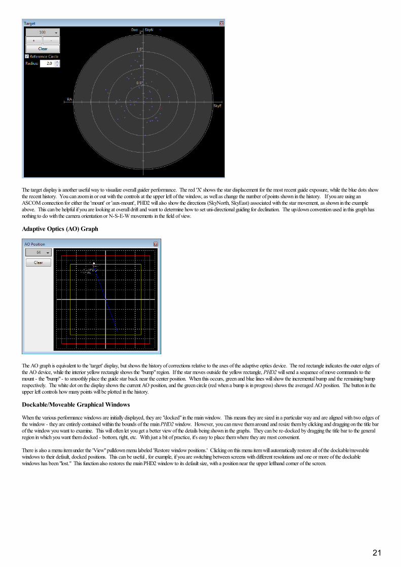
The target display is another useful way to visualize overall guider performance. The red 'X' shows the star displacement for the most recent guide exposure, while the blue dots showthe recent history. You can zoom in or out with the controls at the upper left of the window, as well as change the number of points shown in the history. If you are using anASCOM connection for either the 'mount' or 'aux-mount', PHD2 will also show the directions (SkyNorth, SkyEast) associated with the star movement, as shown in the exampleabove. This can be helpful if you are looking at overall drift and want to determine how to set uni-directional guiding for declination. The up/down convention used in this graph hasnothing to do with the camera orientation or N-S-E-W movements in the field of view.
Adaptive Optics (AO) Graph
The AO graph is equivalent to the 'target' display, but shows the history of corrections relative to the axes of the adaptive optics device. The red rectangle indicates the outer edges ofthe AO device, while the interior yellow rectangle shows the "bump" region. If the star moves outside the yellow rectangle, PHD2 will send a sequence of move commands to themount - the "bump" - to smoothly place the guide star back near the center position. When this occurs, green and blue lines will show the incremental bump and the remaining bumprespectively. The white dot on the display shows the current AO position, and the green circle (red when a bump is in progress) shows the averaged AO position. The button in theupper left controls how many points will be plotted in the history.
Dockable/Moveable Graphical Windows
When the various performance windows are initially displayed, they are "docked" in the main window. This means they are sized in a particular way and are aligned with two edges ofthe window - they are entirely contained within the bounds of the main PHD2 window. However, you can move them around and resize them by clicking and dragging on the title barof the window you want to examine. This will often let you get a better view of the details being shown in the graphs. They can be re-docked by dragging the title bar to the generalregion in which you want them docked - bottom, right, etc. With just a bit of practice, it's easy to place them where they are most convenient.
There is also a menu item under the 'View" pulldown menu labeled 'Restore window positions.' Clicking on this menu item will automatically restore all of the dockable/moveablewindows to their default, docked positions. This can be useful , for example, if you are switching between screens with different resolutions and one or more of the dockablewindows has been "lost." This function also restores the main PHD2 window to its default size, with a position near the upper lefthand corner of the screen.
21
Advanced Settings
Advanced settings are accessed by clicking on the 'Brain button', a feature well-known to users of the original PHD. PHD2 has a considerablylarger set of parameters that can be adjusted to optimize your guiding performance. Although these are called "advanced" settings, they are notparticularly difficult to understand, and you shouldn't hesitate to explore them. All of the fields on these forms include "tool tips", small messagewindows that describe each field in some detail. Simply "hover" the cursor over the field to see the tool-tip. In many cases, this will provide all theinformation you need. Because there are many more settings available, the Advanced Dialog in PHD2 is organized into notebook tabs that areactivated by clicking on the tab names. All of the tabs share a common set of 'Ok' and 'Cancel' buttons at the bottom of the form. Clicking on'Ok' means that changes made to any of the tab fields will be put into effect. Clicking on 'Cancel' discards any changes that were made.
Global TabCamera TabGuiding TabAlgorithms TabOther Devices Tab
Global Tab
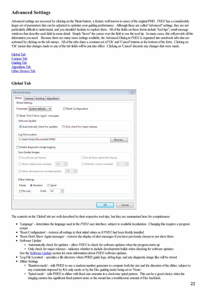
The controls on the 'Global' tab are well-described by their respective tool-tips, but they are summarized here for completeness:
'Language' - determines the language used in the PHD2 user interface, subject to available localization. Changing this requires a programrestart'Reset Configuration' - restores all settings to their initial values as if PHD2 had been freshly installed'Reset Don't Show Again messages' - restores the display of alert messages if you have previously chosen to not show themSoftware Update
Automatically check for updates - allow PHD2 to check for software updates when the program starts upOnly check for major releases - indicates whether to include development builds when checking for software updates.
See the Software Update section for more information about PHD2 software updates.'Log File Location' - specifies a file directory where PHD2 guide logs, debug logs, and any diagnostic image files will be stored.Dither Settings
'Random mode' - tells PHD2 to use a random-number generator to compute both the size and the direction of the dither, subject toany constraints imposed by RA-only mode or by the Dec guiding mode being set to 'None'.'Spiral mode' - tells PHD2 to dither with fixed-size amounts in a clockwise spiral pattern. This can be a good choice when theimaging camera has significant fixed-pattern noise or the mount has a troublesome amount of Dec backlash.
22
'Dither RA only' - tells PHD2 to dither only on the RA axis.'Dither scale' - an optional multiplier used to adjust the maximum-dither amount specified by the image application. See DitheringOperations
'Enable diagnostic image logging' - used primarily for product support and diagnosis of problems dealing with PHD2 star-recognition andmeasurement. However, it can be used to examine and analyze guide frame images for any other purpose as well. Guide frame images arecaptured and logged in a FITs format subject to the filter/trigger controls in the group-box. Images are saved in sub-folders of the PHD2logging directory with the date and time encoded as part of the sub-folder name. Individual guide frames are saved with filenames thatindicate the time the image was captured and the reason the frame was saved. Since the guide frames are saved in a FITs format, theheader will include other useful information such as exposure time. Because the logging function is primarily used for trouble-shooting, theimage sub-folders are automatically removed after 30 days. If you wish to keep the images for your own purposes, you should eitherrename the sub-folders or copy/move them to a different directory. When logging is triggered by one of the "events" - e.g. lost star or largeerrors - a group of images (an image set) will be saved, centered in time on the image that triggered the event. This provides a record ofguider images that will show what the guide star and guide frame looked like both before and after the unusual condition occurred. Thevarious triggering and filtering controls are described below and are also shown in the tooltips for the controls:
'All lost star frames' - logs the image set for any lost-star events, regardless of the reason for the lost star (low SNR, mass-change,etc.)'All auto-select star frames' - logs the image set for any frames used for auto-selection of the star, regardless of outcome. Note thatany failed attempts to auto-select a star will always result in a logged image, regardless of choices made in the user interface.'When relative error exceeds' - logs the image set when the star deflection on the current frame exceeds the running-average error bythe factor chosen in the adjacent spin control. For example, if the average (RMS) error is 0.5 pixels and the current frame's error is1.5 pixels, the relative error is 3.'When absolute error exceeds' - logs the image set when the star deflection exceeds the number of pixels specified in the adjacentspin control.'Until this count is reached' - logs images until the count matches the value of the adjacent spin control. The counter is reset to zerowhen the limit is reached.
Camera Tab
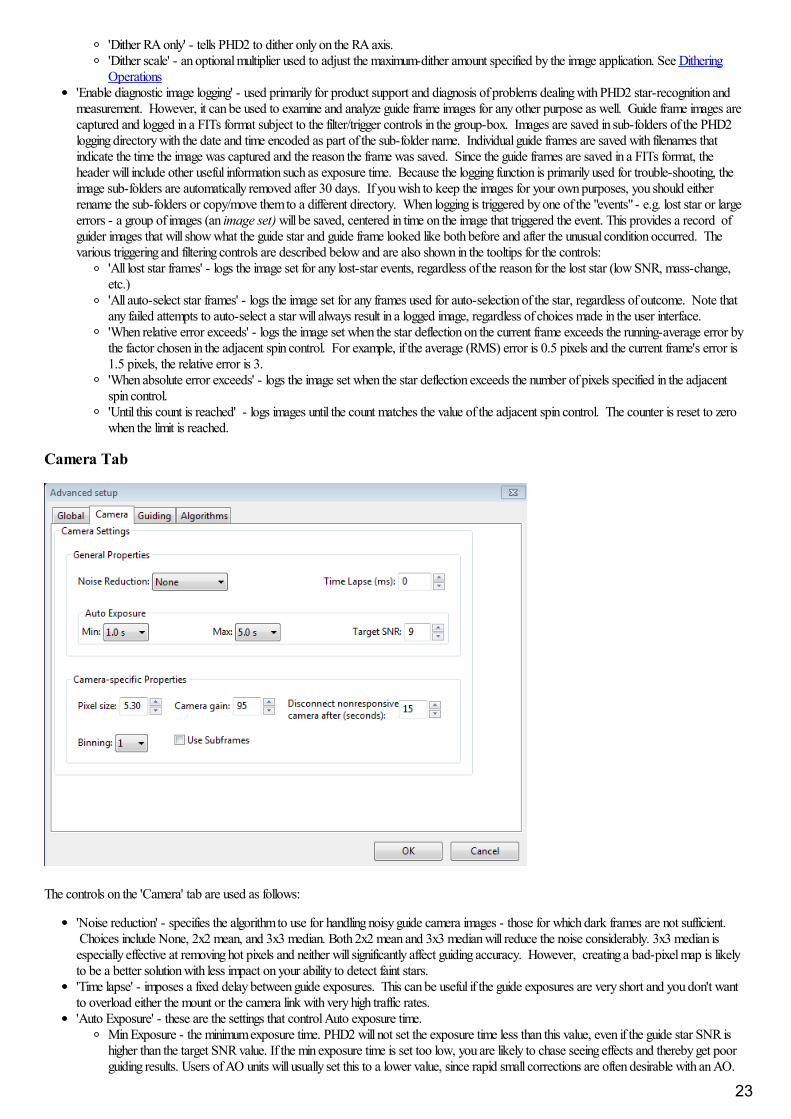
The controls on the 'Camera' tab are used as follows:
'Noise reduction' - specifies the algorithm to use for handling noisy guide camera images - those for which dark frames are not sufficient. Choices include None, 2x2 mean, and 3x3 median. Both 2x2 mean and 3x3 median will reduce the noise considerably. 3x3 median isespecially effective at removing hot pixels and neither will significantly affect guiding accuracy. However, creating a bad-pixel map is likelyto be a better solution with less impact on your ability to detect faint stars.'Time lapse' - imposes a fixed delay between guide exposures. This can be useful if the guide exposures are very short and you don't wantto overload either the mount or the camera link with very high traffic rates.'Auto Exposure' - these are the settings that control Auto exposure time.
Min Exposure - the minimum exposure time. PHD2 will not set the exposure time less than this value, even if the guide star SNR ishigher than the target SNR value. If the min exposure time is set too low, you are likely to chase seeing effects and thereby get poorguiding results. Users of AO units will usually set this to a lower value, since rapid small corrections are often desirable with an AO.
23
Max Exposure - the maximum exposure time. Before a guide star is selected, PHD2 will set the exposure time to the maximum value.Once a guide star is selected, PHD2 will then incrementally decrease the exposure time until the desired SNR is reached.Target SNR - this is the average SNR value that PHD2 will attempt to achieve by adjusting the exposure time. SNR can fluctuatefrom frame to frame even with a fixed exposure duration, so be sure to account for that when choosing a target SNR value. PHD2will reject frames when SNR drops below 3.0. The default value of 6.0 should provide enough of a cushion to prevent fluctuationsfrom causing the SNR to go below 3.0. As mentioned in the 'Basic Use' section, SNR is similar but not identical to the signal-to-noise ratio used in photometry.
'Pixel size' - The guide camera pixel size in microns. This is the second of two parameters needed by PHD2 to compute the guider imagescale and thus report guider statistics in units of arc-seconds. The other parameter required for this is the guide scope focal length, locatedon the 'Guiding' tab. Refer to your camera documentation to determine the correct value for pixel size. If your camera has non-squarepixels, just choose one of the dimensions or input the average of the two. The pixel size has no effect on guiding accuracy, so a smallamount of imprecision in the user interface won't cause any problems. If you're using the binning setting in this dialog to control camerabinning, the pixel size should be the native, un-binned size. Note: this control may be disabled if the camera and camera driver can reportthe pixel size to PHD2. In that case, the value displayed in the disabled control represents the device-reported pixel size - it is what it is. Ifyou're also specifying a binning factor at the camera driver level rather than in PHD2, the reported pixel size may change as a result. It isgenerally better to use PHD2 to set binning (see below).'Camera gain' - Sets the gain level for the many cameras that support this feature. Reducing this parameter can help to reduce the noiselevel or may allow use of a bright star without saturation.'Disconnect nonresponsive camera after (seconds) - Camera malfunctions will sometimes occur, often because of faulty USB connections. In many cases, the camera will not return the requested image data, and PHD2 will appear to "hang." This parameter determines how longPHD2 should wait for a response after the expected exposure time has expired. For example, a timeout value of 5 seconds in conjunctionwith an exposure time of 2 seconds will tell PHD2 to wait up to 7 seconds for a response. If the data are not received within that period,PHD2 will attempt to halt the operation, disconnect the camera, and display an alert message in the main window. Since a hardwareproblem is likely the underlying issue, this recovery attempt won't always succeed. You should be generous with these timeout values toavoid spurious recovery actions. Also, if you are using a guide camera that shares electronics with the main imaging camera, you should setthis timeout to a large value, well above the maximum expected time for a full-frame download from the main imager. This is a considerationfor users of the SBIG driver that is packaged with Sequence Generator Pro. Regardless of whether PHD2 is able to handle the situationgracefully, the underlying problem is almost certainly in the hardware or the camera driver and will need to be resolved before guiding iscontinued.Binning - for those cameras that support on-chip (hardware) binning, you can specify the binning that will be used while taking guideexposures. See below for a more detailed discussion. This control will appear only if the camera is capable of on-chip binning and only ifthe camera is connected to PHD2.'Use subframes' - For cameras that support this feature, PHD2 will download only a subframe of each guide exposure. This is very usefulfor cameras with slow download times, allowing them to be used more effectively for guiding. This feature applies to both calibration andguiding. During initial looping without a selected star, the full frame is downloaded, but once a star is selected, only this small subframe isdownloaded. If you are using subframes but want to see the full frame to select a different star, just shift-click anywhere in the imagedisplay window.
Use of BinningSome of the guide cameras available in PHD2 support hardware-level binning, and this may be helpful in situations where you are guiding at longfocal lengths or have a guide camera with very small pixels. These scenarios often result in having to use faint guide stars, and the guider imagesmay be substantially over-sampled. Over-sampling provides no real benefit, and the projection of a faint star disk onto many small pixels canresult in a low signal-to-noise ratio (SNR). By binning the image, you can reduce the impact of camera read noise and thus improve the SNR; andif you are over-sampled, you won't degrade the accuracy of computing the guide star location. Choosing a binning factor greater than one willhave the following effects:
1. Star images will have a higher SNR and will be easier to detect above the background noise level. This is only beneficial if you are limited toa choice among faint stars (i.e. with SNR values near the threshold of 3).
2. The amount of data downloaded from the camera will be reduced by the square of the binning factor. This can be helpful if you are using acamera that makes heavy use of USB resources even if star brightness and SNR are already reasonable with un-binned images. Of course,using sub-frames can achieve the same result once a star has been selected.
3. The resolution (image scale) of your guider image will be reduced by the binning factor. This is not likely to be a problem if the un-binnedimage scale is below 1 arc-sec/pixel, but your guiding results may suffer if the un-binned image scale is well above 1 arc-sec/pixel. You mayneed to experiment because the results will also depend on the image scale of your main camera system.
Each binning level requires its own dark frames and bad-pixel map - they are not interchangeable, nor can a transform be done automatically. Ifyou foresee the need to switch back and forth between binning settings, you should create separate profiles for each binning value. Then build adark library and a bad-pixel map for each of those profiles. When you want to change binning factors, just switch to the profile that has the settingyou want, and a dark library and/or bad-pixel map will be available. If you want to check that the camera is binning correctly, you can use theStats window to confirm the firame size and current on-camera bin settings.
Guiding Tab
24
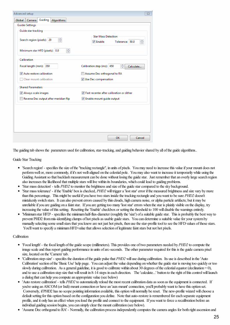
The guiding tab shows the parameters used for calibration, star-tracking, and guiding behavior shared by all of the guide algorithms..
Guide Star Tracking
'Search region' - specifies the size of the "tracking rectangle", in units of pixels. You may need to increase this value if your mount does notperform well or, more commonly, if it's not well-aligned on the celestial pole. You may also want to increase it temporarily while using theGuiding Assistant so that backlash measurement can be done without losing the guide star. Just remember that an overly large search regionalso increases the likelihood that multiple stars will live within its boundaries, which could lead to guiding problems.'Star mass detection' - tells PHD2 to monitor the brightness and size of the guide star compared to the sky background. 'Star mass tolerance' - if the 'Enable' box is checked, PHD2 will trigger a 'lost star' error if the measured brightness and size vary by morethan this percentage. This might be useful if you have two stars inside the tracking rectangle and you want to be sure PHD2 doesn'tmistakenly switch stars. It can also prevent errors caused by thin clouds, high camera noise, or alpha particle artifacts; but it may beunreliable if you are guiding on a faint star. If you are getting too many 'lost star' errors when the star is plainly visible on the display, tryincreasing the value of this setting. Resetting the 'Enable' checkbox or setting the threshold to 100 will disable the warnings entirely.'Minimum star HFD' - specifies the minimum half-flux-diameter (roughtly the 'size') of a suitable guide star. This is probably the best way toprevent PHD2 from mis-identifying clumps of hot pixels as usable guide stars. You can determine a suitable value for your system bymanually selecting some small stars that you know are not just hot pixels, then use the star-profile tool to see the HFD values of those stars. You'll want to specify a minimum HFD value that allows selection of legitimate faint stars but not hot pixels.
Calibration
'Focal length' - the focal length of the guide scope (millimeters). This provides one of two parameters needed by PHD2 to compute theimage scale and thus report guiding performance in units of arc-seconds. The other parameter required for this is the guide camera pixelsize, located on the 'Camera' tab.'Calibration step-size' - specifes the duration of the guide pulse that PHD2 will use during calibration. Its use is described in the 'AutoCalibration' section of the 'Basic Use' help page. You can adjust the value depending on whether the guide star is moving too quickly or tooslowly during calibration. As a general guideline, it is good to calibrate within about 30 degrees of the celestial equator (declination = 0),and to use a calibration step size that will result in 8-14 steps in each direction. The 'calculate...' button to the right of this control will launcha dialog that can help you compute an appropriate value (see below) 'Auto restore calibration' - tells PHD2 to automatically reload the most recent calibration data as soon as the equipment is connected. Ifyou're using an ASCOM (or Indi) mount connection or have an 'aux-mount' connection, you'll probably want to have this option set. Conversely, if PHD2 has no scope pointing information available, this option will normally be reset. The new-profile wizard will choose adefault setting for this option based on the configuration you define. Note that auto-restore is remembered for each separate equipmentprofile, and it only has an effect when you load the profile and connect to the equipment. If you want to force a recalibration before anindividual guiding session begins, you can simply clear the mount calibration (see below).'Assume Dec orthogonal to RA' - Normally, the calibration process independently computes the camera angles for both right ascension and
25
declination. There is no need for great precision on these values, and the default behavior normally works well. However, if your mount hasvery high periodic error or you are dealing with very bad seeing conditions, you may want to force the RA and Declination angles to beperpendicular. If you choose that option, PHD2 will compute the camera angle for RA, then assert a declination angle that is orthogonal toit.'Clear mount calibration' - tells PHD2 you want to clear the calibration data currently being used for the mount and re-calibrate beforeguiding is restarted. You might do this for a variety of reasons - rotating the guide camera or changing the mount guide speed, for example. You can also accomplish the same result by doing a Shift-Click on the PHD2/guiding icon on the main page, which will force a re-calibration.'Use Declination Compensation' - if PHD2 can get pointing information from the mount via an ASCOM connection ('Mount' or 'Aux'), it willautomatically adjust the RA guide rate based on the current declination. This box should normally be left checked except in unusual cases. For example, SiTech mount controllers evidently apply a compensation automatically, in which case the box should be left un-checked. Don't confuse this option with 'Declination backlash compensation', which is an entirely different feature.
Shared Guiding Parameters
'Fast re-center after calibration or dither' - during calibration or dithering, the mount may be moved a significant distance from the initial"lock" position. If you click this checkbox, PHD2 will move the mount back to the lock position as quickly as possible, using the largestguide commands permitted by the 'Max Duration' settings of your guide algorithms and by the size of your tracking region. This is only anoptimization, so the use of this checkbox is completely optional. If you find that calibration often fails because the star is lost during the fastre-center, you should disable this option. That sort of problem may indicate that you have a large polar alignment error or excessiveperiodic error in RA. You can run the Guiding Assistant to help see what's causing the problem.'Reverse Dec output after meridian flip' - tells PHD2 how to adjust the calibration data after a meridian flip. Some mounts track their 'sideof pier' state and automatically reverse the direction of the declination motor. Most mounts do not do this. In either case, PHD2 needs toknow if the mount will automatically change its behavior based on side-of-pier. You may have difficulty finding information about how yourmount behaves in this respect, so it's probably easiest to just run a quick experiment. With the checkbox disabled, calibrate on one side ofthe pier, then move the mount to the other side. If you are guiding via ASCOM or Indi or are using an 'aux mount' connection, just startguiding. If you're guiding only via ST-4 and PHD2 has no scope pointing information, first select 'Flip Calibration' under the 'Tools' menu,and then start guiding. In either case, if the guiding works normally, leave the box un-checked; but if you see run-away in declination,check the box and repeat the entire procedure, including calibration.'Enable mount guide output' - this is normally checked because it tells PHD2 to send guide commands to the mount. But there are somecircumstances where you might want to disable this, usually because you want to observe the uncorrected behavior of the mount. Forexample, you can disable guider output in order to see the general shape and amplitude of your mount's periodic error or to check theamount of drift from polar mis-alignment.'Stop guiding when mount slews' - a diagnostic option for working with ASCOM mount drivers that may report the slewing statusincorrectly. The option should be left checked unless you know the driver for your mount has this problem (highly unlikely). Also, it willgenerally not detect slews that are initiated by the hand-controller. In any case, PHD2 will continue to try to track the guide star, so slewswill typically result in lost-star notifications - beeping and flashing of the PHD2 image window.
Calibration Step Calculator
26

To use the calculator, be sure the topmost three edit controls are correctly filled in. If you have already specified the focal length and the camerapixel size in the 'Global' and 'Camera' tabs respectively, those fields will already be populated in this form. If you are using an ASCOM connectionto your mount, the fields for "Guide speed" and "Calibration declination" will also have the correct values. Otherwise, you'll need to supply themyourself. The guide speed is specified as a multiple of sidereal speed - most mounts will use something like 1X or 0.5X sidereal, but you canchoose something else. You can leave the 'calibration steps' field at the default value of 12, which is likely to result in a good calibration. Use of asignificantly smaller value raises the likelihood that seeing errors or small mount errors will cause calibration errors . As you change the values inthese fields, PHD2 will recalculate your current image scale and a recommended value for the calibration step-size. If you then click on 'Ok', thatvalue will be inserted into the calibration step-size field of the 'Guiding' dialog. Clicking 'Ok' will also populate the focal length and camera pixelsize fields in the 'Guiding' and 'Camera' tabs, so any changes you made in the calculator will be reflected there as well. However, this will not bedone if you click on 'Cancel' in the calculator dialog. Note that PHD2 never changes the guide speed setting in your mount regardless of what maybe entered in the 'Guide Speed' field.
The goal of the calculator is to recommend a step-size that is likely to result in an accurate calibration without wasting too much time. There is nogreat precision involved in any of this, and there is nothing magic about the choice of 12 steps as a target. As long as you are getting successfulcalibrations without alert messages, the calibration step-size is probably good enough.
Algorithms Tab
27
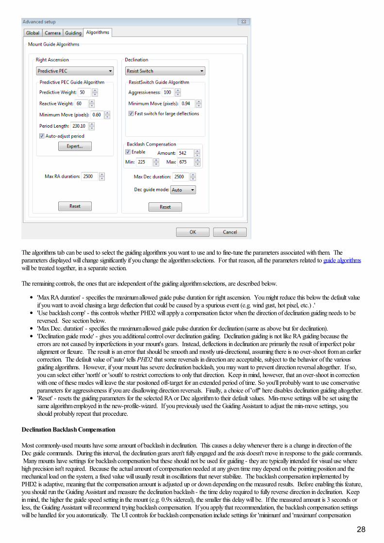
The algorithms tab can be used to select the guiding algorithms you want to use and to fine-tune the parameters associated with them. Theparameters displayed will change significantly if you change the algorithm selections. For that reason, all the parameters related to guide algorithmswill be treated together, in a separate section.
The remaining controls, the ones that are independent of the guiding algorithm selections, are described below.
'Max RA duration' - specifies the maximum allowed guide pulse duration for right ascension. You might reduce this below the default valueif you want to avoid chasing a large deflection that could be caused by a spurious event (e.g. wind gust, hot pixel, etc.) .''Use backlash comp' - this controls whether PHD2 will apply a compensation factor when the direction of declination guiding needs to bereversed. See section below.'Max Dec. duration' - specifies the maximum allowed guide pulse duration for declination (same as above but for declination).'Declination guide mode' - gives you additional control over declination guiding. Declination guiding is not like RA guiding because theerrors are not caused by imperfections in your mount's gears. Instead, deflections in declination are primarily the result of imperfect polaralignment or flexure. The result is an error that should be smooth and mostly uni-directional, assuming there is no over-shoot from an earliercorrection. The default value of 'auto' tells PHD2 that some reversals in direction are acceptable, subject to the behavior of the variousguiding algorithms. However, if your mount has severe declination backlash, you may want to prevent direction reversal altogether. If so,you can select either 'north' or 'south' to restrict corrections to only that direction. Keep in mind, however, that an over-shoot in correctionwith one of these modes will leave the star positoned off-target for an extended period of time. So you'll probably want to use conservativeparameters for aggressiveness if you are disallowing direction reversals. Finally, a choice of 'off'' here disables declination guiding altogether.'Reset' - resets the guiding parameters for the selected RA or Dec algorithm to their default values. Min-move settings will be set using thesame algorithm employed in the new-profile-wizard. If you previously used the Guiding Assistant to adjust the min-move settings, youshould probably repeat that procedure.
Declination Backlash Compensation
Most commonly-used mounts have some amount of backlash in declination. This causes a delay whenever there is a change in direction of theDec guide commands. During this interval, the declination gears aren't fully engaged and the axis doesn't move in response to the guide commands. Many mounts have settings for backlash compensation but these should not be used for guiding - they are typically intended for visual use wherehigh precision isn't required. Because the actual amount of compensation needed at any given time may depend on the pointing position and themechanical load on the system, a fixed value will usually result in oscillations that never stabilize. The backlash compensation implemented byPHD2 is adaptive, meaning that the compensation amount is adjusted up or down depending on the measured results. Before enabling this feature,you should run the Guiding Assistant and measure the declination backlash - the time delay required to fully reverse direction in declination. Keepin mind, the higher the guide speed setting in the mount (e.g. 0.9x sidereal), the smaller this delay will be. If the measured amount is 3 seconds orless, the Guiding Assistant will recommend trying backlash compensation. If you apply that recommendation, the backlash compensation settingswill be handled for you automatically. The UI controls for backlash compensation include settings for 'minimum' and 'maximum' compensation
28

amounts. These effectively limit the range of the adjustments that are made to the starting compensation value. If you're experienced with yourmount's behavior, you can adjust these settings manually to be sure that the compensation stays within a range that you know works well. Otherwise, you should just leave these at their default values. The backlash compensation algorithm will generally work well if the backlash is lessthan a few seconds and the mount doesn't have other significant mechanical problems. You should expect a short period of instability whenguiding starts because the initial state of the Dec gear system is unknown - just let it stabilize before you actually start imaging. If you see recurringperiods of Dec oscillation or the axis won't settle down, disable the compensation feature and submit your debug log file to the PHD2 supportforum.
Uni-directional Declination Guiding
As discussed elsewhere, some mounts have too much declination backlash to support guiding in both north and south directions. This situation canbe mitigated by configuring PHD2 to guide in only one of the directions, what we call uni-directional Dec guiding. This can be a manageablesituation because declination guiding is only intended to correct for slow drift - errors caused by polar misalignment and to a lesser extent,mechanical flexure. Ironically, you might want to de-tune your polar alignment a bit to make it easier to see the drift direction and to reduce thelikelihood that seeing will interfere with uni-directional guiding. Remember that polar mis-alignment, within reason, doesn't usually degrade guidingperformance. Instead, it may introduce field rotation if you're imaging near the pole and have a large camera sensor. A good first step would be topolar align to within a few arc-minutes of the pole before setting up for uni-directional guiding. You can always go back later and check for fieldrotation. Just take a sample image with your main camera at the highest declination you would expect for imaging - perhaps 70 degrees north. Ifyou don't see field rotation there, you can leave the polar alignment where it is. With any amount of polar mis-alignment, the direction of Deccorrections will change at some point in the sky. (Technically, it will reverse directions at two points in the sky but one of those is usually below thehorizon.) The sky location for the reversal depends entirely on how you are mis-aligned on the pole - the relative amounts of azimuth and altitudealignment errors. You may even have a situation where the reversal point is near enough to the horizon that you don't encounter it during normalimaging.
To set up for uni-directional guiding, you can follow these steps:
1. Move to a field with a good guide star and open the Guiding Graph window. Disable Dec guiding entirely by setting the Dec guide mode to'off', then start guiding. Now watch the graph until you can see a clear trend in the way the guide star is drifting either north or south. Onceyou see this, reset the Dec guide mode to issue corrections in the right direction. For example, if the star is drifting north, set the Guidemode to 'south.'
2. Try using the 'LowPass' or 'LowPass2' guiding algorithms for declination and start with a fairly low aggressiveness factor, say 50%. If theaggressiveness is too high, the correction may push the star to the "wrong" side of the lock position, where it will remain until the slow driftrate moves it back. It's better to issue a few consecutive small corrections rather than one larger one in order to minimze this type of over-shoot.
3. Watch the guiding graph to be sure the corrections are being issued in the right direction and the star isn't just steadily drifting off-target. Over the course of minutes or hours, you may notice the amount of drift is decreasing. This means you are slowly approaching the point ofdeclination reversal and you should be prepared to change the Dec guide mode accordingly.
4. If you are dithering, set the dithering parameters to "RA-only" to avoid disrupting the Dec guiding.
Other Devices Tab
29
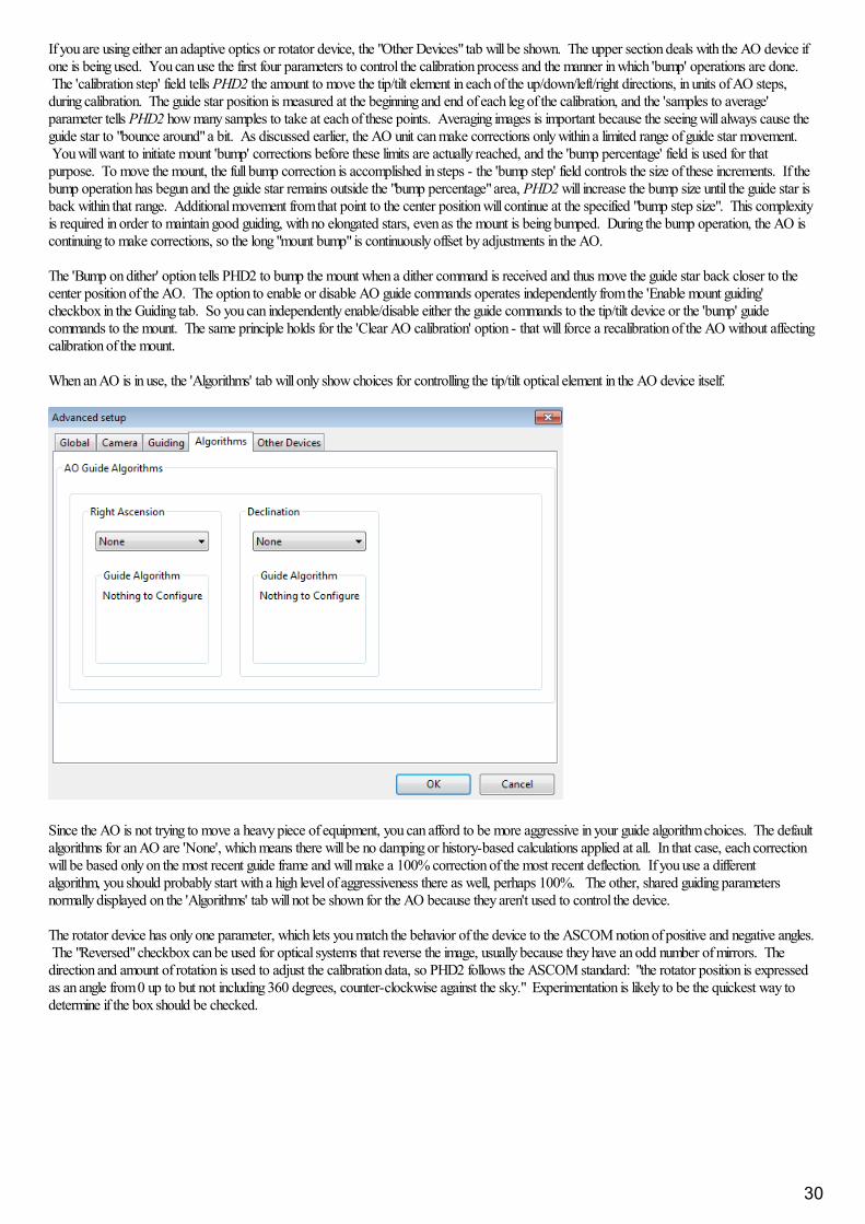
If you are using either an adaptive optics or rotator device, the "Other Devices" tab will be shown. The upper section deals with the AO device ifone is being used. You can use the first four parameters to control the calibration process and the manner in which 'bump' operations are done. The 'calibration step' field tells PHD2 the amount to move the tip/tilt element in each of the up/down/left/right directions, in units of AO steps,during calibration. The guide star position is measured at the beginning and end of each leg of the calibration, and the 'samples to average'parameter tells PHD2 how many samples to take at each of these points. Averaging images is important because the seeing will always cause theguide star to "bounce around" a bit. As discussed earlier, the AO unit can make corrections only within a limited range of guide star movement. You will want to initiate mount 'bump' corrections before these limits are actually reached, and the 'bump percentage' field is used for thatpurpose. To move the mount, the full bump correction is accomplished in steps - the 'bump step' field controls the size of these increments. If thebump operation has begun and the guide star remains outside the "bump percentage" area, PHD2 will increase the bump size until the guide star isback within that range. Additional movement from that point to the center position will continue at the specified "bump step size". This complexityis required in order to maintain good guiding, with no elongated stars, even as the mount is being bumped. During the bump operation, the AO iscontinuing to make corrections, so the long "mount bump" is continuously offset by adjustments in the AO.
The 'Bump on dither' option tells PHD2 to bump the mount when a dither command is received and thus move the guide star back closer to thecenter position of the AO. The option to enable or disable AO guide commands operates independently from the 'Enable mount guiding'checkbox in the Guiding tab. So you can independently enable/disable either the guide commands to the tip/tilt device or the 'bump' guidecommands to the mount. The same principle holds for the 'Clear AO calibration' option - that will force a recalibration of the AO without affectingcalibration of the mount.
When an AO is in use, the 'Algorithms' tab will only show choices for controlling the tip/tilt optical element in the AO device itself.
Since the AO is not trying to move a heavy piece of equipment, you can afford to be more aggressive in your guide algorithm choices. The defaultalgorithms for an AO are 'None', which means there will be no damping or history-based calculations applied at all. In that case, each correctionwill be based only on the most recent guide frame and will make a 100% correction of the most recent deflection. If you use a differentalgorithm, you should probably start with a high level of aggressiveness there as well, perhaps 100%. The other, shared guiding parametersnormally displayed on the 'Algorithms' tab will not be shown for the AO because they aren't used to control the device.
The rotator device has only one parameter, which lets you match the behavior of the device to the ASCOM notion of positive and negative angles. The "Reversed" checkbox can be used for optical systems that reverse the image, usually because they have an odd number of mirrors. Thedirection and amount of rotation is used to adjust the calibration data, so PHD2 follows the ASCOM standard: "the rotator position is expressedas an angle from 0 up to but not including 360 degrees, counter-clockwise against the sky." Experimentation is likely to be the quickest way todetermine if the box should be checked.
30
Guide Algorithms
Guiding TheoryGuide Algorithm Parameters
Guiding Theory
The default guiding algorithms in PHD2 are well-established and should work well for most users. Unless you already have some experience withguiding and understand the basics, you should probably be cautious about changing algorithms. However, you may have some specialcircumstances that require changes or you may simply want to experiment with the different algorithm choices. The Advanced Dialog settings inPHD2 make it easy to do that. Each algorithm has a set of parameters that controls how observed changes in guide star position (star deflections)are translated into guiding commands that are most likely to restore the star to its initial position.
Before discussing the details of these parameters, it is worth reviewing a little guiding theory and looking at what these algorithms are trying toaccomplish. Setting aside adaptive optics devices, which are entirely different, conventional guiding faces enormous challenges. The problem athand is how to move machinery that weighs tens or even hundreds of pounds with a level of precision that will not cause streaked or oblong stars. This type of guiding can only hope to deal with tracking errors that are "slow and steady", not "fast and random." Sources of slow and steady(correctable) errors include the following:
Certain kinds of mechanical imperfections in right ascension gears, including those that cause periodic error.Smalll errors in the sidereal tracking rate of the mountAtmospheric refraction - stars appear to move more slowly as they near the horizonLimited kinds of mechanical deflection and flexure - but not differential flexureMis-alignment of the right ascension axis on the celestial pole
So what isn't included in the above and isn't correctable by conventional guiding? Unfortunately, it's a very long list, of which a few are:
Atmospheric seeing ("turbulence")Gear noise, roughness, and vibrationDifferential flexure - relative movement between the imaging scope and the guide scopeWind gusts, cable snags, grit in the drive gearsAnd lots more...
The common denominator shared by the guide algorithms is the need to somehow react to the slow and steady deflections while ignoring the rest. This is a difficult problem at best because any given guide star deflection is likely to have contributions from many of these sources. And if thatisn't hard enough, remember that real-world mounts are never perfect - so the move you ask for will not be exactly the move you get. Usually, themost important requirement for any algorithm is to avoid over-correcting, wherein the mount is being pushed back and forth and the guiding neverstabilizes. A typical approach in these algorithms is to apply "inertia" or "impedance" to the guiding corrections. That means making correctionsthat follow a pattern and are generally consistent with corrections that have been made before, while being reluctant to make corrections thatrequire a big change in direction or amplitude. Resistance to changes in direction is particularly important in declination, where gear backlash is acommon problem. Hopefully, this background will give you enough insight into the basics of guiding so that the various guiding parameters used inPHD2 will make sense.
Guide Algorithm Parameters
In PHD2, the various guide algorithms can be applied to either the right ascension or declination axes. Most of these algorithms includea minimum move parameter. This is used to avoid making guide corrections that are overly small, are unlikely to have any effect on star shape,and are mostly due to transient seeing effects. These values are entered in units of pixels, so you need to think about them in the context of yourimage scale and the typical size of your guide stars. If you have used the new-profile-wizard to configure your system, the min-move parameterswill be set to values that are likely to work well for the image scale you're using. The Guiding Assistant can also adjust these values based on itsmeasurement of high-frequency seeing disturbances. If you are seeing a high rate of guider corrections and lots of direction reversals, you may be"chasing the seeing" and adjusting the min-move values upward can be a simple way to reduce that. Of all the detailed guiding parametersdiscussed here, the two min-move values are the most likely to warrant adjustment on a nightly basis depending on seeing conditions.
The hysteresis algorithms keep a history of the guiding corrections that have been made in the recent past, and these are used to help computethe next guide correction. The hysteresis parameter, expressed as a percentage, specifies the "weight" that should be given to this history asopposed to looking only at the star deflection in the current guide frame. Consider an example where the hysteresis parameter is 10%. In thatcase, the next guiding correction will be 90% influenced by the star movement seen in the current guide frame and 10% by the corrections thathave been made in the recent past. Increasing the hysteresis value will smooth out the corrections at the risk of being too slow to react to alegitimate change in direction. The hysteresis algorithms also include an aggressiveness parameter, again expressed as a percentage, that is usedto reduce over-correcting. On each frame, PHD2 computes how far it thinks the mount should move and in what direction(s) it should move. Theaggressivness parameter scales this. For example, take a case where the star deflection has been evaluated and a corrective move of 0.5 pixels iswarranted. If the aggressiveness is set to 100%, a guider command will be issued to move the mount the full 0.5 pixels. But if the aggressivenessis set to 60%, the mount will be asked to move only 60% of that amount, or 0.3 pixels. If you find your mount is always overshooting the star,decrease this value slightly (say, by 10% steps). If you find PHD2 always seems to be lagging behind the star's motion, increase this by a little bit.
31
A little can go a long way here.
The ResistSwitch algorithm behaves much as its name implies. Like the hysteresis algorithms, it also maintains a history of past guide corrections,and any change of direction must be "compelling" in order to issue a reversing guide command. This is appropriate for declination guiding, wherereversals in direction are both suspect and likely to trigger backlash in the gears. For that reason, ResistSwitch is the default algorithm fordeclination but not for right ascension, where valid direction reversals are expected. Starting with Release 2.4.1, two additional parameters areavailable for fine-tuning the ResistSwitch algorithm. The first is "aggression", a percentage amount that controls how much of the computed guidecorrection will be issued. Reducing this parameter can help to avoid over-shooting with mounts that have little or no backlash. The secondparameter is a checkbox labeled "Fast switch for large deflections." If this is checked, PHD2 will react immediately to a large change of directionrather than waiting for three consecutive deflections in the new direction, which is the normal behavior. This can help to more quickly recover fromlarge excursions in Dec, perhaps caused by wind, cable snags, or other mechanical shifts The definition of a "large deflection" is 3x the minimum-move value. So if PHD2 is over-reacting to direction changes, you can tune the behavior with the min-move parameter or disable the "fast switch"option altogether. It is worth remembering that "less is usually better" when it comes to Dec guiding, so don't try to over-tune these parameters.
The LowPass algorithms also employ a history of recent guiding corrections in order to compute the next correction. The starting point for thecomputed move is the median value of the guide star deflections that have occurred in recent history. This means that the star deflection seen in thecurrent guide frame has relatively little impact on calculating the next move and the algorithm is very resistant to quick changes. But the historyaccumulation also includes a calculation to determine if deflections are trending in a consistent direction. The slope weight parameter, expressedas a percentage, determines how much influence this should have in calculating the actual guider movement - it is there to keep the algorithm frombeing overly sluggish. If you set a slope weight of zero, the guide pulse will always be just the median value of the recent history. If you set a non-zero slope weight, that median value will be adjusted either upward or downward based on the recent trend of guide star movements. Because thelow-pass algorithm is so resistant to quick changes, it is probably most applicable to declination guiding.
The LowPass2 algorithm is a variation of the original LowPass algorithm with somewhat different behavior. It also maintains a history of guidingcorrections, but the next correction is simply a linear extension of the commands that have come before it (i.e. a slope calculation). This continuesuntil a significant change in direction is seen, at which point the history is cleared. The algorithm has two adjustable properties: minimum-move andaggressiveness. Minimum-move has the same effect as it does in the other guide algorithms, and aggressiveness (percentage) is a way of furtherdampening the size of the guide corrections. LowPass2 is a very conservative, high-impedance algorithm that may be a good choice for users withgood seeing conditions and well-behaved mounts with little or no declination backlash.
PHD2 Predictive PEC Guide Algorithm (PPEC)
Overview
The PPEC algorithm is different from the others in PHD2 because of its modeling and predictive capabilities. The algorithm analyzes the trackingperformance of the mount in real-time and once that analysis is complete, it will compute guiding corrections even before a repetitive error isactually seen. Issuing proactive guiding corrections reduces the time delay inherent in traditional guiding and can significantly improveperformance. With the other algorithms, which are completely reactive, guide corrections are issued only after the error has been seen on thecamera sensor.
Once guiding has begun, the algorithm analyzes the performance of the mount and looks for tracking errors that are repetitive and thus,predictable. The algorithm employs a sophisticated Gaussian process model developed by a research team at the Max Planck Institute inGermany. The mathematical details can be found in a paper referenced here:
http://ieeexplore.ieee.org/document/7105398/?reload=true
The PPEC algorithm will normally be used for RA, where residual periodic error and other gear-related errors often reduce tracking accuracy. The algorithm uses separate time-scales for characterizing the behavior of the system:
· Short-term: for high-frequency errors such as those caused by gear roughness or seeing· Medium-term: for residual periodic errors, typically occurring at intervals less than or equal to the worm period· Longer-term: for steady drift and for lower frequency (longer time interval) harmonics that can be caused by the interaction of multiple gears inthe drive train
The short-term behavior is used to identify the unpredictable noise in the system, which is essentially filtered out in order to identify componentsthat are predictable. For most mounts, the medium-term component is likely to be the most important. If you’re following best practices, you willhave programmed periodic error correction in your mount (assuming that feature is available to you). Doing this reduces the amount of work thatneeds to be done by PHD2, and the PEC correction in the mount is normally saved permanently. This approach is preferable to having tomeasure and infer the periodic error behavior every time you set up your equipment. That said, PEC in the mount is never perfect, and you willoften see residual repetitive errors even when PEC is active. These often arise when the tracking errors occur with a frequency that is not aharmonic (integer fraction) of the mount’s worm period – most PEC implementations can’t deal with those. You can also get residual periodicerrors if they are dependent on the mechanical loading of the mount or if the mount’s behavior has changed since the PEC was programmed. ThePPEC algorithm can be quite effective at identifying and reducing these errors because it doesn’t depend on the worm period and is always doing afresh analysis of the mount’s current behavior.
The PPEC algorithm will also detect and proactively correct for drift errors. Although drift is typically handled well by any of the guide algorithms,
32
the corrections will always lag the error by some amount. For some use cases – perhaps spectroscopy, photometry or comet-tracking – this mightbe a problem, in which case PPEC may deliver better results.
Since PPEC employs a learning process, it will usually take about 2 worm periods to model the mount and become fully effective. During thistraining period, the algorithm will behave more like the ‘hysteresis’ algorithm, so you won’t normally see a performance penalty while the internalmodel is being built. Instead, you’re likely to see a steady improvement in tracking as the model is refined and the algorithm shifts seamlessly fromhysteresis to predictive-mode. This improvement can usually be seen even before the medium-term mount behavior is fully modeled.
Since the PPEC model is implicitly tied to the state of the gear train, it must be re-learned if the mount is slewed to a new target. For the samereason, it can’t be retained across different guiding sessions, which is why conventional PEC is important. However, the PPEC model will remainintact during dither operations and while guiding is paused (via automation) for activities like focusing. For the most common use-case, namelyimaging the same target for multiple hours with periodic dithering, the PPEC model will remain valid. In any case, the learning process andtransition from one mode to the other is handled automatically, so you won’t need to pay it any attention.
Algorithm Details
Once the training period is completed, the PPEC algorithm computes the guide correction using two factors. One is reactive, based on thedisplacement of the guide star in the most recent exposure. The second is predictive, based on the output from the Gaussian process modelconstructed during the training period. Each of these terms includes a separate gain or aggressiveness factor, so the final guide pulse amount is asum:
Guide-correction = (predicted amount * predictive gain) + (recent displacement * reactive gain)
The ‘predictive gain’ and ‘reactive gain’ parameters are exposed in the Advanced Dialog, and their default values for these parameters shouldwork well for most mounts. You should be conservative about changing them because bad choices for these parameters can definitely make yourguiding worse.
During the training period, the algorithm needs to identify periodic errors in the observed guide star movement. For initial trials, you can use theworm period of your mount as the starting point for the ‘period length’. This gives the algorithm a good starting point, but you should also leavethe ‘auto-adjust period’ option checked. This tells the algorithm to adjust the period as needed to better control whatever periodic errors it finds. Once you have run the altorithm multiple times and are happy with the results, you can leave this field set to whatever value was computed in theprevious sessions.
The ‘min-move’ parameter affects only the reactive component of the algorithm. If the measured star displacement is less than this amount, thereactive component will be set to zero. However, the predictive component of the algorithm will still be computed and applied.
33

Tools and Utilities
Manual GuideAuto-Select StarCalibration DetailsPHD2 ServerDithering OperationsLogging and Debug OutputPolar Alignment ToolsLock PositionsComet TrackingGuiding AssistantEquipment ProfilesAsk for Coordinates Aux MountSimulator ParametersMultiple Program InstancesKeyboard ShortcutsSoftware Update
Manual Guide
If you are connecting to a new mount and are encountering calibration problems, you will probably want to be sure that PHD2's commands areactually getting to the mount. Or you may want to nudge the mount or experiment with manual dithering. In the 'Tools' menu, click on 'ManualGuide' and a dialog will appear to let you move the mount at guide speed in any direction. If you have an adaptive optics device attached, you'llsee separate move buttons for both the AO and the secondary mount. Each time you press the button, a pulse of the duration specified in the'Guide Pulse Duration' field will be sent. The default value is the 'calibration step-sze' set in the Advanced Options dialog. If you are debuggingmount/calibration problems in the daytime, listen to (rather than watch) your mount to determine if it is getting the commands from PHD2. The ideahere is just to figure out if the mount is responding to PHD2's signals. You won't be able to see the mount move (it's moving at guide speed) butyou may be able to hear the motors. Other options include watching the motors and gears or attaching a laser pointer to your scope and aiming itat something fairly far away (to amplify your motions). A better approach for nighttime testing is to run the "star-cross" test described here.
Dithering is used primarily with image capture or automation applications through the PHD2 server interface. However, you can do manualdithering or experiment with dither settings using the controls at the bottom of the dialog. The 'dither' amount field at the left controls the amountthe mount will be moved , in units of pixels. You can scale this amount - i.e. multiply it by a constant - by using the 'scale' spin control to the right. These two controls establish a maximum amount of movement that will be used for dithering - the product of 'scale' X 'dither'. When you click onthe 'Dither' button, PHD2 will move the mount by a random amount that is less than or equal to the limit you have set, in one of thenorth/south/east/west directions. The 'RA Only' checkbox will constrain the dither adjustments to only east or west. Obviously, if you are doing amanual dither in this way, you'll want to be sure your imaging camera is not in the middle of an exposure.
Auto-Select Star
Clicking on 'Auto-select Star' under the 'Tools' menu, or using the keyboard shortcut of <Alt>S, tells PHD2 to scan the current guide image andidentify a star suitable for guiding. PHD2 will try to select a star of sufficient brightness that is not saturated, not near another star, and not tooclose to the edge of the frame. The selected star may appear fairly dim on the screen, but that's usually not important - just adjust the gamma slideron the main window. The auto-select function will usually do a better job than you can just looking at the display. In many cases, a star youchoose interactively is at or near saturation and will produce sub-par results. You can use the Star Profile tool to examine the properties of theselected star, however it was chosen. If you want to use Auto-Select, you should definitely use either a bad-pixel map or dark library to reducethe likelihood of PHD2 mistakenly choosing a hot pixel.
Calibration Details34

Most of the calibration-related windows, including calibration sanity-checks, will open a window that looks something like this:
The first thing to look at is the graph to the left, which shows what star movements resulted from the guide pulses that PHD2 sent duringcalibration. The lines represent the RA and Dec guide rates that were computed as a result of the calibration, and these lines should be roughlyperpendicular. The data points will never be perfectly aligned, but they should not have major curves, sharp inflections, or reversals in direction.Particularly with longer focal length scopes, the points will often show considerable scatter around the lines, but this is normal. The solid points(west and north pulses) are used to compute the RA and declination rates, while the hollow points show the "return" paths of the east and southmoves. These can help you see how much fluctuation occurred due to seeing and also whether there is a significant amount of backlash. If you areusing the "fast-recenter" option in the Advanced Settings, there may be many fewer points shown in the east and north paths. The tabularinformation to the right shows what was known about the pointing position of the scope and the various ASCOM settings that relate to guiding. Ifyou are not using an ASCOM mount and don't have an "Aux mount" specified, some of this information will be missing. The table will also showthe expected guiding rates for a "perfect" calibration using the same sky position and guide speed settings you used. You will almost never achievethese ideal values, and you shouldn't worry about them unless your values are very different. If you didn't see an alert message when thecalibration completed, your results are probably good enough. If you want to re-use a calibration for an extended time, it is probably worth afew extra minutes to check this information and confirm that the calibration went reasonably well and produced sensible results. Bad calibrationscan occur even for very experienced imagers using high-end mounts, so it is good to check.
If you are having consistent problems getting alert-free calibrations, you should review the material in the trouble-shooting section .
Other Calibration-Related Menu OptionsCalibration data are saved automatically each time a calibration sequence completes successfully. The use of the calibration data has beendescribed elsewhere (Using PHD Guiding), including options for restoring calibration data from an earlier time or "flipping" it after a meridian flip. You access these functions using the 'Modify Calibration' sub-menu under the 'Tools' menu. Two other calibration-related items are shown there,namely the options to clear the current data or to enter calibration data manually. The "clear" option accomplishes the same thing as the 'Clearcalibration' checkbox in the Advanced Dialog - it will force a recalibration whenever guiding is resumed. The 'Enter calibration data' option shouldbe used only under very unusual circumstances and only if you're sure you know what you're doing; but it is available as a matter of completeness. If you click on the 'Enter calibration data' item, you'll see a dialog box that allows input of relatively low-level calibration data. This data mightcome from a much earlier session, perhaps extracted from the PHD2 guiding log file. Keep in mind, if you are using an ASCOM driver for eitherthe 'mount' or 'aux mount' connections, you should have little need for these calibration data controls.
PHD2 Server
PHD2 supports third-party imaging and automation applications that need to control the guiding process. Stark Labs' Nebulosity program wasthe first to do this, but other applications have subsequently been produced. By using the PHD2 server process, image capture programs cancontrol dithering between exposures or suspend guide exposures while the primary imaging camera is downloading data. To use these capabilitieswith a compatible application, you should click on the 'Enable Server' option under the 'Tools' menu. The server interface has been reworkedsubstantially in PHD2, and it's now possible for an application to control most aspects of PHD2's guiding operations. Documentation for theserver API is available on the PHD2 Wiki.
Dithering
The primary purpose of dithering is to make post-processing easier by removing some kinds of fixed-pattern noise in the images, especially hotpixels. This is almost purely a function of the camera you're using and to a lesser extent, the sophistication of the post-processing software. Forimagers with temperature-regulated, low-noise cameras, dithering is mostly a convenient way to eliminate hot pixels that aren't getting removed by
35
the dark frames. Hot pixel positions change as sensors age, so dark libraries don't usually correct for all of them. Those hot pixels can also be alsoremoved in post-processing, but that becomes tedious if there are lots of them. It's also possible that dithering can help with some other kinds ofsensor behavior such as column defects, and it's particularly helpful if there is no temperature regulation on the sensor and therefore no good wayto use a dark library. DSLR imagers often use aggressive dithering for those reasons. In the PHD2 implementation, automated dithering isaccomplished through the server interface, so make sure you have 'Enable Server' checked under the 'Tools' menu. You first specify a maximumdither size you want to use during the guiding session - this will be set in your imaging application.. Then, when that application issues a dithercommand, PHD2 uses a random number generator to decide how large the dither will actually be for that command. The actual dither mount willbe > 0 and <= the maximum amount allowed. You want to use pseudo-random dither amounts like this to be sure that dithering doesn't follow aconsistent pattern or shift the frame back to a location where it has previously been. But for some of the applications that do PHD2 dithering, youcan't specify the maximum amount directly - you are perhaps limited to choices like small/medium/large and the max dither amounts will havepreset values. For that reason, PHD2 has a dither scaling parameter in the 'Global' tab of the Brain dialog. It is basically a multiplier term that letsyou adjust the range of dither amounts that are possible. So a scale factor of 1 doesn't change the preset value at all, a value of 10 multiplies it by10X, etc. If you're using an app that lets you specify the maximum amount directly (e.g. PHD_Dither), you should leave the dither scale set to1.0. Otherwise, you can adjust the scale factor if you aren't happy with the overall range of dithering you're getting with one of thesmall/medium/large type imaging apps.
There are typically two costs associated with dithering: 1) the extra time and uncertainty required for "settling" and 2) the need to crop the finalstacked frame in order to remove the low-signal margins. Settling is the term used for a period of stabilization after the mount has been moved bya dither command. The imaging app that starts the dither will also decide when the guiding has stabilized enough to continue imaging. The appcan let PHD2 determine this by specifying the settling parameters or the app can do the calculations itself. You'll need to look at yourimaging/dithering app to see what control you have over this process. If the app uses the latest PHD2 server interfaces, it can specify a settlingrequirement that might look like "guiding errors must be less than 1.5 pixels for a period of at least 10 seconds." This is a process that canconsume some time, depending on how tight the requirements are for settling. It is likely to take more time if you are dithering in declination andthe dither forces a change in direction. Most mounts have some declination backlash, so it can take a number of guide commands to get the mountmoving in the right direction, and then more time for the process to converge on the new target location for the guide star. That's why PHD2 alsooffers the option to dither only in right ascension. Again, this is an option on the 'Global' tab, right next to the dither scaling parameter.
If your mount has a substantial amount of declination backlash in the mount, you may be guiding in only the north or south Dec direction. If PHD2receives a command to dither in declination while you're operating in this mode, it will temporarily allow guiding in both Dec directions until thedither and settling are completed. It will then revert to the original north/south-only guiding mode. If you don't want this behavior, you shouldrestrict dithering to 'RA-only' ('Global tab of the Brain dialog).
Logging and Debug Output
PHD2 automatically creates two types of log files: a debug log and a guiding log. Both are very useful for different reasons. The guiding log issimilar to the one produced by PHD, but with extended information. The guide log is intentionally formatted to allow easy interpretation by either ahuman reader or an external application. For example, the very capable PHDLogView application (not part of the PHD2 release) can produce avariety of graphs and summary statistics based on data in the PHD2 guide log. But the log can also be easily imported into Excel or otherapplications for analysis and graphing. When importing into Excel, just specify that a comma should be used as a column separator. The debuglog has a complete record of everything that was done in the PHD2 session, so it is very helpful in isolating any problems you have. It alsoemploys a human-friendly (albeit verbose) text format, so it's not difficult to examine the debug log to see what happened. If you need to report aproblem with the software, you will almost certainly be asked to provide the debug log file. If you have neither log file available, you are unlikely toget any help.
The location for the files is controlled by the 'Log File Location' field in the 'Global' tab of the 'Advanced Settings' dialog. By default, log files arestored in the OS-specific default directory for user documents. In Windows7, for example, the files will be stored in a 'PHD2' sub-folder in the"Documents" directory. This may not be a convenient location, so you can specify a different folder using this edit field. In order to preventexcessive accumulation of log files, PHD2 automatically removes debug logs that are more than 30 days old and guide logs that are more than 60days old. If you want to retain the files for longer periods, you should move or copy them to a different folder location, one not used by PHD2.
In some unusual cases, you may need to capture guide camera images, usually to support debugging and problem resolution. This can be done byclicking the 'Enable Star Imaging Logging' menu item under the 'Tools' menu. The resultant image files will be stored in the same location as theother log files. The format of these image files is controlled from the 'Global' tab of the 'Advanced Settings' dialog. If you are trying to document aproblem you're having, you should choose the 'Raw Fits' format for maximum flexibility.
Automatic Log File Upload
If you need help using PHD2 or improving your guiding results, you'll want to post a request on the Open-PHD-Guiding forum(https://groups.google.com/forum/#!forum/open-phd-guiding). Your question should be accompanied by the PHD log files associated with theguiding session you're talking about. To make that easier, PHD2 has a built-in function to select, compress, and automatically upload the relevantlog files. That function is located on the 'Help' menu. You'll see a dialog box that shows all the available log files, including their timestamps andduration:
36
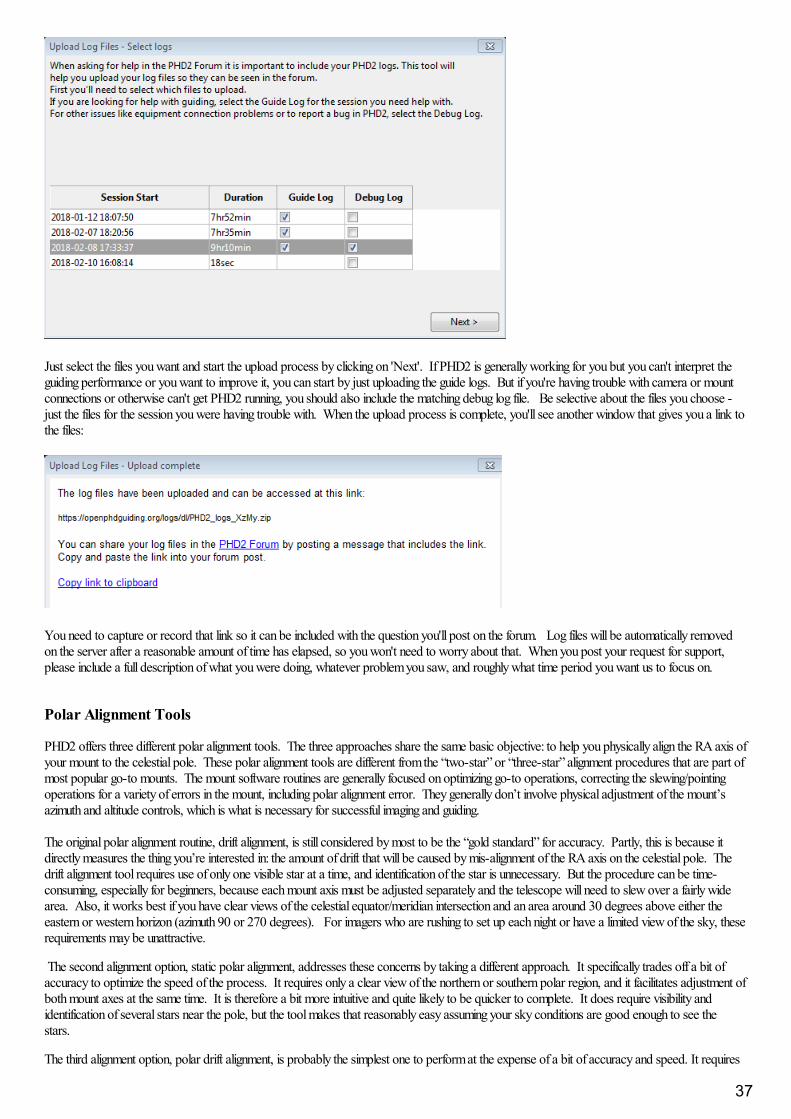
Just select the files you want and start the upload process by clicking on 'Next'. If PHD2 is generally working for you but you can't interpret theguiding performance or you want to improve it, you can start by just uploading the guide logs. But if you're having trouble with camera or mountconnections or otherwise can't get PHD2 running, you should also include the matching debug log file. Be selective about the files you choose -just the files for the session you were having trouble with. When the upload process is complete, you'll see another window that gives you a link tothe files:
You need to capture or record that link so it can be included with the question you'll post on the forum. Log files will be automatically removedon the server after a reasonable amount of time has elapsed, so you won't need to worry about that. When you post your request for support,please include a full description of what you were doing, whatever problem you saw, and roughly what time period you want us to focus on.
Polar Alignment Tools
PHD2 offers three different polar alignment tools. The three approaches share the same basic objective: to help you physically align the RA axis ofyour mount to the celestial pole. These polar alignment tools are different from the “two-star” or “three-star” alignment procedures that are part ofmost popular go-to mounts. The mount software routines are generally focused on optimizing go-to operations, correcting the slewing/pointingoperations for a variety of errors in the mount, including polar alignment error. They generally don’t involve physical adjustment of the mount’sazimuth and altitude controls, which is what is necessary for successful imaging and guiding.
The original polar alignment routine, drift alignment, is still considered by most to be the “gold standard” for accuracy. Partly, this is because itdirectly measures the thing you’re interested in: the amount of drift that will be caused by mis-alignment of the RA axis on the celestial pole. Thedrift alignment tool requires use of only one visible star at a time, and identification of the star is unnecessary. But the procedure can be time-consuming, especially for beginners, because each mount axis must be adjusted separately and the telescope will need to slew over a fairly widearea. Also, it works best if you have clear views of the celestial equator/meridian intersection and an area around 30 degrees above either theeastern or western horizon (azimuth 90 or 270 degrees). For imagers who are rushing to set up each night or have a limited view of the sky, theserequirements may be unattractive.
The second alignment option, static polar alignment, addresses these concerns by taking a different approach. It specifically trades off a bit ofaccuracy to optimize the speed of the process. It requires only a clear view of the northern or southern polar region, and it facilitates adjustment ofboth mount axes at the same time. It is therefore a bit more intuitive and quite likely to be quicker to complete. It does require visibility andidentification of several stars near the pole, but the tool makes that reasonably easy assuming your sky conditions are good enough to see thestars.
The third alignment option, polar drift alignment, is probably the simplest one to perform at the expense of a bit of accuracy and speed. It requires
37

a clear view of the northern or southern polar region, and it facilitates adjustment of both mount axes at the same time. Minimal user input is neededso it is very simple to use.
The three techniques are described in detail in the following sections. Imagers should probably experiment with them and choose the one that bestsuits their needs. The importance of alignment accuracy is often over-emphasized, so users need to keep things in perspective. Most declinationdrift can be well-managed by PHD2 guiding assuming the mount behaves well and doesn’t have a lot of declination backlash. However, at somepoint, the amount of polar alignment error can create field rotation in the images, something that can’t be corrected. The larger the imaging sensorand the closer to the pole the target is, the more field rotation can be an issue. You can compute the expected field rotation using an onlinecalculator such as this one:
http://celestialwonders.com/tools/rotationMaxErrorCalc.html
The calculator can help you decide how much accuracy is “good enough” for your situation. It’s also important to remember that either procedurecan be limited by the precision of the adjustment mechanisms on the mount.
Drift Alignment Tool
Static Polar Alignment Tool
Polar Drift Alignment Tool
Lock Positions
PHD2 normally sets a 'lock position' where the guide star is located at the end of calibration. Depending on the details of the calibration sequence,this may not be exactly where the star was located at the start of calibration - it could be off by a few pixels. If you are trying to precisely centeryour target, you may want to use a 'sticky lock position.' You do this by clicking on your guide star before calibration, then setting the 'StickyLock Position' under the 'Tools' menu. After calibration is complete, PHD2 will continue to move the mount until the star is located at the stickylock position. So you may see an additional delay after the calibration while PHD2 repositions the scope at guide speed. The sticky lock positionwill continue to be used even as guiding is stopped and subsequently resumed. Again, this insures a rigorous positioning of the guide star (andpresumably your image target) at the expense of delays needed for PHD2 to reposition the mount.
If you need to fine-tune the position of the guide star on the camera sensor after guiding has begun, you can use the 'Adjust Lock Position' functionunder the Tools menu:
You can nudge the guide star in small increments (at guide speed) or you can move it by a larger amount by typing in a new lock position andclicking 'Set'. Clicking on the up/down/left/right buttons will cause the lock position to be shifted in the corresponding direction by the amountshown in 'Step', and the revised lock position will be displayed If you type in a new lock position, you run the risk of losing the guide star if thenew position falls outside the current search region. This tool is useful if you need to achieve precise positioning of either the guide star or theimaging target, for example with spectroscopy..
Comet Tracking
One way to image a comet is to have PHD2 use the comet as the guide "star", but this approach may not always work. For example, the head ofthe comet may not present a star-like center suitable for guiding. Or, when using an off-axis guider, the comet may not even be visible in the guidecamera.
PHD2 provides a Comet Tracking tool for use when guiding on the comet itself is not feasible. The idea is to guide on an ordinary star, but togradually shift the lock position to match the comet's motion, or tracking rate.
There are a three different ways to provide the comet tracking rate to PHD2.
Some planetarium applications, like Cartes du Ciel, can send the rate directly to PHD2;You can enter the tracking rate manually, or,You can train the rate in PHD2 by following the comet for a period of time in the imaging camera.
38
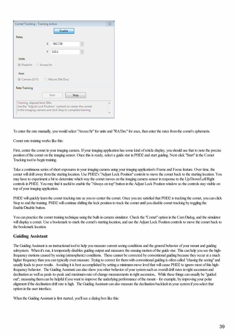
To enter the rate manually, you would select "Arcsec/hr" for units and "RA/Dec" for axes, then enter the rates from the comet's ephemeris.
Comet rate training works like this:
First, center the comet in your imaging camera. If your imaging application has some kind of reticle display, you should use that to note the preciseposition of the comet on the imaging sensor. Once this is ready, select a guide star in PHD2 and start guiding. Next click "Start" in the CometTracking tool to begin training.
Take a continuous series of short exposures in your imaging camera using your imaging application's Frame and Focus feature. Over time, thecomet will drift away from the starting location. Use PHD2's "Adjust Lock Position" controls to move the comet back to the starting location. Youmay have to experiment a bit to determine which way the comet moves on the imaging camera sensor in response to the Up/Down/Left/Rightcontrols in PHD2. You may find it useful to enable the "Always on top" button in the Adjust Lock Position window so the controls stay visible ontop of your imaging application.
PHD2 will quickly learn the comet tracking rate as you re-center the comet. Once you are satisfied that PHD2 is tracking the comet, you can clickStop to end the training. PHD2 will continue shifting the lock position to track the comet until you disable comet tracking by toggling theEnable/Disable button.
You can practice the comet training technique using the built-in camera simulator. Check the "Comet" option in the Cam Dialog, and the simulatorwill display a comet. Use a bookmark to mark the comet's starting location, and use the Adjust Lock Position controls to move the comet back tothe bookmark location.
Guiding Assistant
The Guiding Assistant is an instructional tool to help you measure current seeing conditions and the general behavior of your mount and guidingsubsystem. When it's run, it temporarily disables guiding output and measures the ensuing motion of the guide star. This can help you see the high-frequency motions caused by seeing (atmospheric) conditions. These cannot be corrected by conventional guiding because they occur at a muchhigher frequency than you can typically even measure. Trying to correct for them with conventional guiding is often called "chasing the seeing" andusually leads to poor results. Avoiding it is best accomplished by setting a minimum-move level that will cause PHD2 to ignore most of this high-frequency behavior. The Guiding Assistant can also show you other behavior of your system such as overall drift rates in right ascension anddeclination as well as peak-to-peak and maximum-rate-of-change measurements in right ascension,. While these things can usually be "guidedout", measuring them can be helpful if you want to improve the underlying performance of the mount - for example, by improving your polaralignment if the declination drift rate is high. The Guiding Assistant can also measure the declination backlash in your system if you select thatoption in the user interface.
When the Guiding Assistant is first started, you'll see a dialog box like this:
39
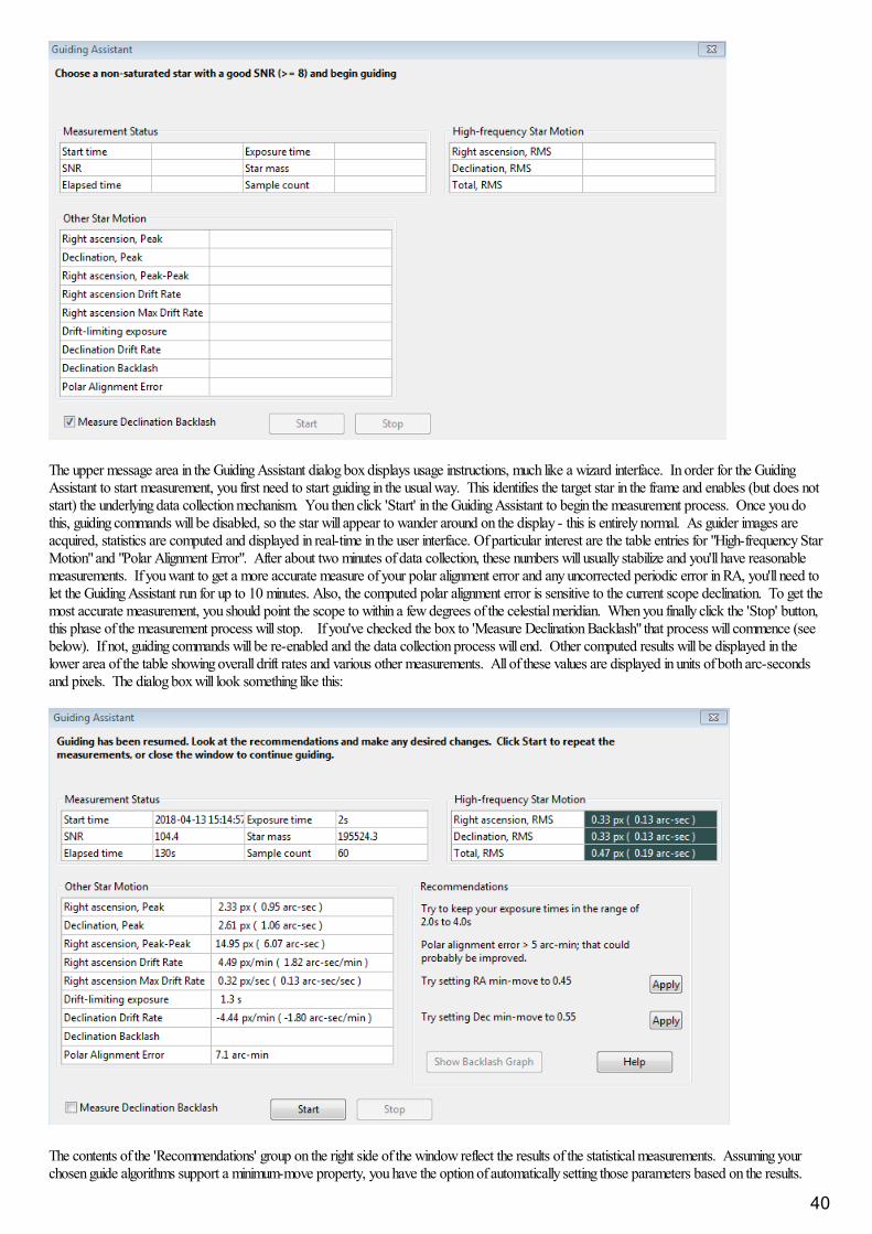
The upper message area in the Guiding Assistant dialog box displays usage instructions, much like a wizard interface. In order for the GuidingAssistant to start measurement, you first need to start guiding in the usual way. This identifies the target star in the frame and enables (but does notstart) the underlying data collection mechanism. You then click 'Start' in the Guiding Assistant to begin the measurement process. Once you dothis, guiding commands will be disabled, so the star will appear to wander around on the display - this is entirely normal. As guider images areacquired, statistics are computed and displayed in real-time in the user interface. Of particular interest are the table entries for "High-frequency StarMotion" and "Polar Alignment Error". After about two minutes of data collection, these numbers will usually stabilize and you'll have reasonablemeasurements. If you want to get a more accurate measure of your polar alignment error and any uncorrected periodic error in RA, you'll need tolet the Guiding Assistant run for up to 10 minutes. Also, the computed polar alignment error is sensitive to the current scope declination. To get themost accurate measurement, you should point the scope to within a few degrees of the celestial meridian. When you finally click the 'Stop' button,this phase of the measurement process will stop. If you've checked the box to 'Measure Declination Backlash" that process will commence (seebelow). If not, guiding commands will be re-enabled and the data collection process will end. Other computed results will be displayed in thelower area of the table showing overall drift rates and various other measurements. All of these values are displayed in units of both arc-secondsand pixels. The dialog box will look something like this:
The contents of the 'Recommendations' group on the right side of the window reflect the results of the statistical measurements. Assuming yourchosen guide algorithms support a minimum-move property, you have the option of automatically setting those parameters based on the results.
40

You can also decide to re-run the measurements or close the dialog box altogether if you want to proceed with normal guiding operations.
Measuring Declination BacklashIf you've checked the box to 'Measure Declination Backlash', that process will begin as soon as the high-frequency measurements are completed. In other words, clicking once on the 'Stop' button halts the high-frequency measurements and begins the measurement of declination backlash. However, if the initial sampling period was less than 2 minutes, a dialog box will appear and the backlash test will continue to sample until the 2-minute period has expired. A new group of status messages will be shown immediately above the 'Start' and 'Stop' buttons so you can see what'sbeing done:
To do backlash measurement, PHD2 will move the star by large amounts, first in the north direction, then back to the south. There is some riskthe star will be lost during this process or the star might already be too close to the north edge of the sensor. You should choose a guide star thathas plenty of room to move north to get the best accuracy. If the star is lost because it's been moved outside the search region, you cantemporarily increase the size of that region from the 'Guiding' tab of the Advanced Settings dialog. A search region size of 20 pixels should workfor most configurations - just be sure you don't have multiple stars inside the search region. The first phase of backlash measurement involves aninitial attempt to clear whatever backlash is present in the north direction. The Guiding Assistant (GA) will continue with these clearing commandsuntil it sees a significant and consistent movement of the guide star in one direction. Once this is done, the GA will issue another sequence ofcommands to continue moving the star north by a large amount. This will take at least 16 seconds and may take longer depending on theconfiguration - you can watch the status update to see what's being done. When the north steps are finished, the GA will issue an identical numberof steps in the south direction. If there's significant backlash in the mount, it may take a long time for the star to start moving south, but that willusually be handled. Once the south steps are done, regardless of how far the star has actually moved, the backlash amount will be computed. However, if the star hasn’t moved at all in the south direction, the computed backlash amount will be too small. At that point, you can know yourdeclination backlash exceeds 8 seconds, which is a very large amount. The Guiding Assistant will then try to move the star back to its startingposition and will re-enable guiding. Again, there is some risk the star may be lost, but this won't affect the calculations - you can simply stop andresume guiding as you normally would. Unlike the first process for measuring high-frequency star movement, you don't need to click on the 'Stop'button once backlash measurement has begun. The measurement process will terminate when all the steps have been completed, and normalguiding will be resumed. However, you can click on the 'Stop' button if something has gone wrong - such as a lost-star condition - and then restartwhen you're ready. When the backlash tests are finished, you'll see the results displayed as before, with the addition of entries for the amount ofdeclination backlash and the measurement uncertainty::
41

Depending on the amount of backlash, you may see a recommendation for setting a backlash compensation factor - 390 ms in the example shownabove. This type of backlash compensation is different from the feature offered in many mount controllers and is described here: PHD2 backlashcompensation If the measured amount is less than 100 ms, no recommendation will be made because such a small amount probably doesn'twarrant any compensation. If the backlash is very large, over 3 seconds, you'll see a different recommendation to use uni-directional guiding indeclination. That's because trying to compensate for such large values probably won't work very well, and the mount will probably not be able toreverse directions quickly enough to support bi-directional guiding. Obviously, you can reach your own conclusions based on your experience withhow the mount behaves. Before doing these measurements, be sure to disable any backlash compensation that's previously been enabled in themount software. If this isn't done, the measurements and any subsequent attempts at compensation by PHD2 will be invalid. If you want to tryuni-directional guiding, you can find instructions here: Uni-directional guiding
You can look at a graphical display of the backlash measurement results to get a better understanding of how the mount performed. Just click onthe 'Show Graph' button to see a graph that might look something like this:
The red points show the measured declination positions, shown left to right, beginning with the north moves and ending with the south (return)moves. The blue points show the south-return behavior for a perfect mount with zero backlash. In this example, there is only a modest amount ofbacklash as evidenced by the flattened top of the red points. However, the flattened top will be much more pronounced when there is significantlymore declination backlash in the mount, as in the following example:
42
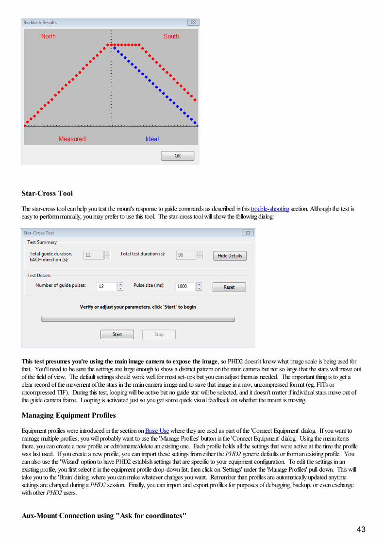
Star-Cross Tool
The star-cross tool can help you test the mount's response to guide commands as described in this trouble-shooting section. Although the test iseasy to perform manually, you may prefer to use this tool. The star-cross tool will show the following dialog:
This test presumes you're using the main image camera to expose the image, so PHD2 doesn't know what image scale is being used forthat. You'll need to be sure the settings are large enough to show a distinct pattern on the main camera but not so large that the stars will move outof the field of view. The default settings should work well for most set-ups but you can adjust them as needed. The important thing is to get aclear record of the movement of the stars in the main camera image and to save that image in a raw, uncompressed format (eg. FITs oruncompressed TIF). During this test, looping will be active but no guide star will be selected, and it doesn't matter if individual stars move out ofthe guide camera frame. Looping is activiated just so you get some quick visual feedback on whether the mount is moving.
Managing Equipment Profiles
Equipment profiles were introduced in the section on Basic Use where they are used as part of the 'Connect Equipment' dialog. If you want tomanage multiple profiles, you will probably want to use the 'Manage Profiles' button in the 'Connect Equipment' dialog. Using the menu itemsthere, you can create a new profile or edit/rename/delete an existing one. Each profile holds all the settings that were active at the time the profilewas last used. If you create a new profile, you can import these settings from either the PHD2 generic defaults or from an existing profile. Youcan also use the 'Wizard' option to have PHD2 establish settings that are specific to your equipment configuration. To edit the settings in anexisting profile, you first select it in the equipment profile drop-down list, then click on 'Settings' under the 'Manage Profiles' pull-down. This willtake you to the 'Brain' dialog, where you can make whatever changes you want. Remember than profiles are automatically updated anytimesettings are changed during a PHD2 session. Finally, you can import and export profiles for purposes of debugging, backup, or even exchangewith other PHD2 users.
Aux-Mount Connection using "Ask for coordinates"
43
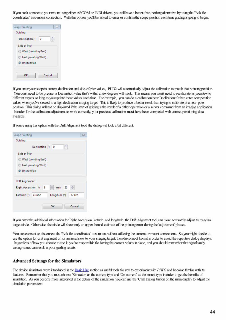
If you can't connect to your mount using either ASCOM or INDI drivers, you still have a better-than-nothing alternative by using the "Ask forcoordinates" aux-mount connection. With this option, you'll be asked to enter or confirm the scope position each time guiding is going to begin::
If you enter your scope's current declination and side-of-pier values, PHD2 will automatically adjust the calibration to match that pointing position. You don't need to be precise, a Declination value that's within a few degrees will work. This means you won't need to recalibrate as you slew todifferent targets so long as you update these values each time. For example, you can do a calibration near Declination=0 then enter new positionvalues when you've slewed to a high declination imaging target. This is likely to produce a better result than trying to calibrate at a near-poleposition. This dialog will not be displayed if the start of guiding is the result of a dither operation or a server command from an imaging application. In order for the calibration adjustment to work correctly, your previous calibration must have been completed with correct positioning dataavailable.
If you're using this option with the Drift Alignment tool, the dialog will look a bit different:
If you enter the additional information for Right Ascension, latitude, and longitude, the Drift Alignment tool can more accurately adjust its magentatarget circle. Otherwise, the circle will show only an upper-bound estimate of the pointing error during the 'adjustment' phases.
You can connect or disconnect the "Ask for coordinates" aux-mount without affecting the camera or mount connections. So you might decide touse the option for drift alignment or for an initial slew to your imaging target, then disconnect from it in order to avoid the repetitive dialog displays. Regardless of how you choose to use it, you're responsible for having the correct values in place, and you should remember that significantlywrong values can result in poor guiding results.
Advanced Settings for the Simulators
The device simulators were introduced in the Basic Use section as useful tools for you to experiment with PHD2 and become famliar with itsfeatures. Remember that you must choose 'Simulator' as the camera type and 'On-camera' as the mount type in order to get the benefits ofsimulation. As you become more interested in the details of the simulation, you can use the 'Cam Dialog' button on the main display to adjust thesimulation parameters:
44
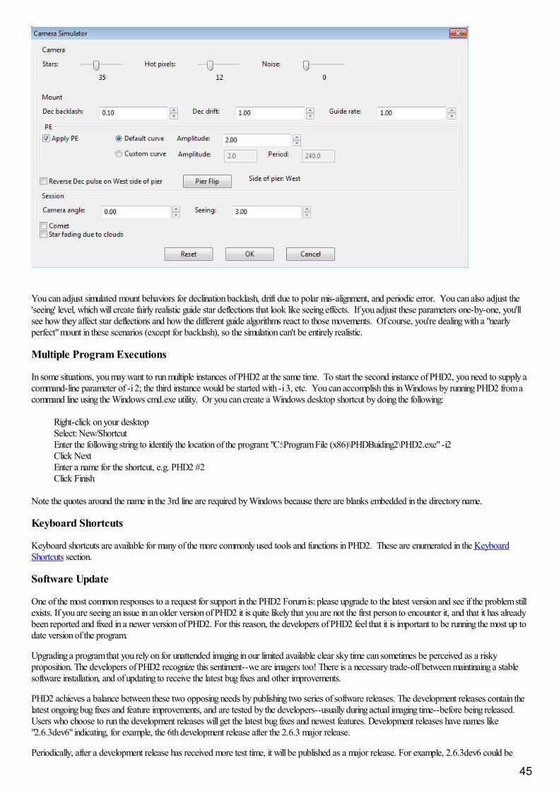
You can adjust simulated mount behaviors for declination backlash, drift due to polar mis-alignment, and periodic error. You can also adjust the'seeing' level, which will create fairly realistic guide star deflections that look like seeing effects. If you adjust these parameters one-by-one, you'llsee how they affect star deflections and how the different guide algorithms react to those movements. Of course, you're dealing with a "nearlyperfect" mount in these scenarios (except for backlash), so the simulation can't be entirely realistic.
Multiple Program Executions
In some situations, you may want to run multiple instances of PHD2 at the same time. To start the second instance of PHD2, you need to supply acommand-line parameter of -i 2; the third instance would be started with -i 3, etc. You can accomplish this in Windows by running PHD2 from acommand line using the Windows cmd.exe utility. Or you can create a Windows desktop shortcut by doing the following:
Right-click on your desktopSelect: New/ShortcutEnter the following string to identify the location of the program: "C:\Program File (x86)\PHDBuiding2\PHD2.exe" -i2Click NextEnter a name for the shortcut, e.g. PHD2 #2Click Finish
Note the quotes around the name in the 3rd line are required by Windows because there are blanks embedded in the directory name.
Keyboard Shortcuts
Keyboard shortcuts are available for many of the more commonly used tools and functions in PHD2. These are enumerated in the KeyboardShortcuts section.
Software Update
One of the most common responses to a request for support in the PHD2 Forum is: please upgrade to the latest version and see if the problem stillexists. If you are seeing an issue in an older version of PHD2 it is quite likely that you are not the first person to encounter it, and that it has alreadybeen reported and fixed in a newer version of PHD2. For this reason, the developers of PHD2 feel that it is important to be running the most up todate version of the program.
Upgrading a program that you rely on for unattended imaging in our limited available clear sky time can sometimes be perceived as a riskyproposition. The developers of PHD2 recognize this sentiment--we are imagers too! There is a necessary trade-off between maintinaing a stablesoftware installation, and of updating to receive the latest bug fixes and other improvements.
PHD2 achieves a balance between these two opposing needs by publishing two series of software releases. The development releases contain thelatest ongoing bug fixes and feature improvements, and are tested by the developers--usually during actual imaging time--before being released.Users who choose to run the development releases will get the latest bug fixes and newest features. Development releases have names like"2.6.3dev6" indicating, for example, the 6th development release after the 2.6.3 major release.
Periodically, after a development release has received more test time, it will be published as a major release. For example, 2.6.3dev6 could be
45

published as major release 2.6.4.
Checking for updates
PHD2 has an option to automatically check for software updates. We recommend enabling this option to help keep your version of PHD2 up todate. When the automatic check option is enabled, PHD2 will quietly check for updates in the background when PHD2 starts. If new updates areavailable, PHD2 will give you the option to install the new version. Enabling the automatic check for updates will not interfere with the ordinaryoperation of PHD2, including automated operation. It is also safe to leave the option enabled if you are imaging in the field without internetconnectivity. If PHD2 cannot check for updates, it will wait until next time it is started before trying to check again.
Regardless of whether you allow PHD2 to automatically check for updates at startup, you can always manually check for updates by clicking"Check for updates" from the Help menu.
46
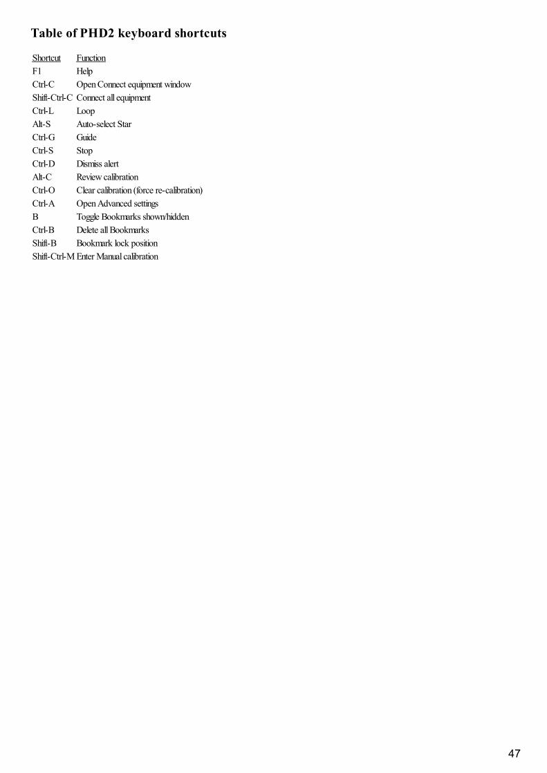
Table of PHD2 keyboard shortcuts
Shortcut FunctionF1 HelpCtrl-C Open Connect equipment windowShift-Ctrl-C Connect all equipmentCtrl-L LoopAlt-S Auto-select StarCtrl-G GuideCtrl-S StopCtrl-D Dismiss alertAlt-C Review calibrationCtrl-O Clear calibration (force re-calibration)Ctrl-A Open Advanced settingsB Toggle Bookmarks shown/hiddenCtrl-B Delete all BookmarksShift-B Bookmark lock positionShift-Ctrl-M Enter Manual calibration
47
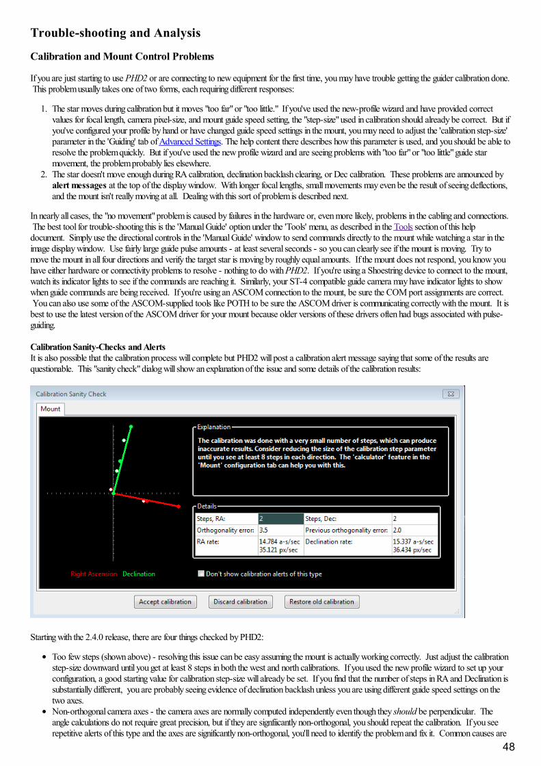
Trouble-shooting and Analysis
Calibration and Mount Control Problems
If you are just starting to use PHD2 or are connecting to new equipment for the first time, you may have trouble getting the guider calibration done. This problem usually takes one of two forms, each requiring different responses:
1. The star moves during calibration but it moves "too far" or "too little." If you've used the new-profile wizard and have provided correctvalues for focal length, camera pixel-size, and mount guide speed setting, the "step-size" used in calibration should already be correct. But ifyou've configured your profile by hand or have changed guide speed settings in the mount, you may need to adjust the 'calibration step-size'parameter in the 'Guiding' tab of Advanced Settings. The help content there describes how this parameter is used, and you should be able toresolve the problem quickly. But if you've used the new profile wizard and are seeing problems with "too far" or "too little" guide starmovement, the problem probably lies elsewhere.
2. The star doesn't move enough during RA calibration, declination backlash clearing, or Dec calibration. These problems are announced byalert messages at the top of the display window. With longer focal lengths, small movements may even be the result of seeing deflections,and the mount isn't really moving at all. Dealing with this sort of problem is described next.
In nearly all cases, the "no movement" problem is caused by failures in the hardware or, even more likely, problems in the cabling and connections. The best tool for trouble-shooting this is the 'Manual Guide' option under the 'Tools' menu, as described in the Tools section of this helpdocument. Simply use the directional controls in the 'Manual Guide' window to send commands directly to the mount while watching a star in theimage display window. Use fairly large guide pulse amounts - at least several seconds - so you can clearly see if the mount is moving. Try tomove the mount in all four directions and verify the target star is moving by roughly equal amounts. If the mount does not respond, you know youhave either hardware or connectivity problems to resolve - nothing to do with PHD2. If you're using a Shoestring device to connect to the mount,watch its indicator lights to see if the commands are reaching it. Similarly, your ST-4 compatible guide camera may have indicator lights to showwhen guide commands are being received. If you're using an ASCOM connection to the mount, be sure the COM port assignments are correct. You can also use some of the ASCOM-supplied tools like POTH to be sure the ASCOM driver is communicating correctly with the mount. It isbest to use the latest version of the ASCOM driver for your mount because older versions of these drivers often had bugs associated with pulse-guiding.
Calibration Sanity-Checks and AlertsIt is also possible that the calibration process will complete but PHD2 will post a calibration alert message saying that some of the results arequestionable. This "sanity check" dialog will show an explanation of the issue and some details of the calibration results:
Starting with the 2.4.0 release, there are four things checked by PHD2:
Too few steps (shown above) - resolving this issue can be easy assuming the mount is actually working correctly. Just adjust the calibrationstep-size downward until you get at least 8 steps in both the west and north calibrations. If you used the new profile wizard to set up yourconfiguration, a good starting value for calibration step-size will already be set. If you find that the number of steps in RA and Declination issubstantially different, you are probably seeing evidence of declination backlash unless you are using different guide speed settings on thetwo axes.Non-orthogonal camera axes - the camera axes are normally computed independently even though they should be perpendicular. Theangle calculations do not require great precision, but if they are signfiicantly non-orthogonal, you should repeat the calibration. If you seerepetitive alerts of this type and the axes are significantly non-orthogonal, you'll need to identify the problem and fix it. Common causes are
48
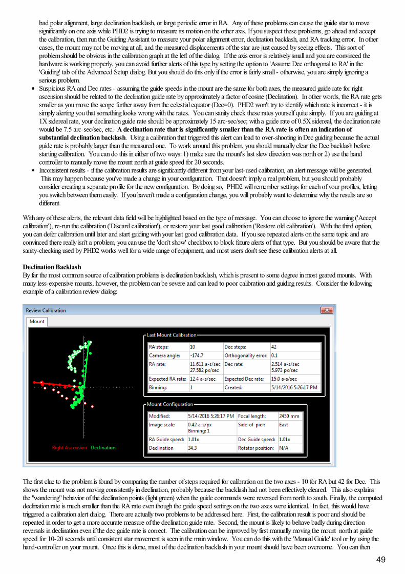
bad polar alignment, large declination backlash, or large periodic error in RA. Any of these problems can cause the guide star to movesignificantly on one axis while PHD2 is trying to measure its motion on the other axis. If you suspect these problems, go ahead and acceptthe calibration, then run the Guiding Assistant to measure your polar alignment error, declination backlash, and RA tracking error. In othercases, the mount may not be moving at all, and the measured displacements of the star are just caused by seeing effects. This sort ofproblem should be obvious in the calibration graph at the left of the dialog. If the axis error is relatively small and you are convinced thehardware is working properly, you can avoid further alerts of this type by setting the option to 'Assume Dec orthogonal to RA' in the'Guiding' tab of the Advanced Setup dialog. But you should do this only if the error is fairly small - otherwise, you are simply ignoring aserious problem. Suspicious RA and Dec rates - assuming the guide speeds in the mount are the same for both axes, the measured guide rate for rightascension should be related to the declination guide rate by approximately a factor of cosine (Declination). In other words, the RA rate getssmaller as you move the scope further away from the celestial equator (Dec=0). PHD2 won't try to identify which rate is incorrect - it issimply alerting you that something looks wrong with the rates. You can sanity check these rates yourself quite simply. If you are guiding at1X sidereal rate, your declination guide rate should be approximately 15 arc-sec/sec; with a guide rate of 0.5X sidereal, the declination ratewould be 7.5 arc-sec/sec, etc. A declination rate that is significantly smaller than the RA rate is often an indication ofsubstantial declination backlash. Using a calibration that triggered this alert can lead to over-shooting in Dec guiding because the actualguide rate is probably larger than the measured one. To work around this problem, you should manually clear the Dec backlash beforestarting calibration. You can do this in either of two ways: 1) make sure the mount's last slew direction was north or 2) use the handcontroller to manually move the mount north at guide speed for 20 seconds. Inconsistent results - if the calibration results are significantly different from your last-used calibration, an alert message will be generated. This may happen because you've made a change in your configuration. That doesn't imply a real problem, but you should probablyconsider creating a separate profile for the new configuration. By doing so, PHD2 will remember settings for each of your profiles, lettingyou switch between them easily. If you haven't made a configuration change, you will probably want to determine why the results are sodifferent.
With any of these alerts, the relevant data field will be highlighted based on the type of message. You can choose to ignore the warning ('Acceptcalibration'), re-run the calibration ('Discard calibration'), or restore your last good calibration ('Restore old calibration'). With the third option,you can defer calibration until later and start guiding with your last good calibration data. If you see repeated alerts on the same topic and areconvinced there really isn't a problem, you can use the 'don't show' checkbox to block future alerts of that type. But you should be aware that thesanity-checking used by PHD2 works well for a wide range of equipment, and most users don't see these calibration alerts at all.
Declination BacklashBy far the most common source of calibration problems is declination backlash, which is present to some degree in most geared mounts. Withmany less-expensive mounts, however, the problem can be severe and can lead to poor calibration and guiding results. Consider the followingexample of a calibration review dialog:
The first clue to the problem is found by comparing the number of steps required for calibration on the two axes - 10 for RA but 42 for Dec. Thisshows the mount was not moving consistently in declination, probably because the backlash had not been effectively cleared. This also explainsthe "wandering" behavior of the declination points (light green) when the guide commands were reversed from north to south. Finally, the computeddeclination rate is much smaller than the RA rate even though the guide speed settings on the two axes were identical. In fact, this would havetriggered a calibration alert dialog. There are actually two problems to be addressed here. First, the calibration result is poor and should berepeated in order to get a more accurate measure of the declination guide rate. Second, the mount is likely to behave badly during directionreversals in declination even if the dec guide rate is correct. The calibration can be improved by first manually moving the mount north at guidespeed for 10-20 seconds until consistent star movement is seen in the main window. You can do this with the 'Manual Guide' tool or by using thehand-controller on your mount. Once this is done, most of the declination backlash in your mount should have been overcome. You can then
49
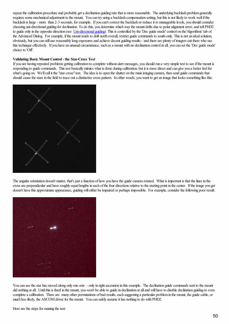
repeat the calibration procedure and probably get a declination guiding rate that is more reasonable. The underlying backlash problem generallyrequires some mechanical adjustment to the mount. You can try using a backlash compensation setting, but this is not likely to work well if thebacklash is large - more than 2-3 seconds, for example. If you can't correct the backlash or reduce it to manageable levels, you should considerchoosing uni-directional guiding for declination. To do this, you determine which way the mount drifts due to polar alignment error, and tell PHD2to guide only in the opposite direction (see Uni-directional guiding). This is controlled by the 'Dec guide mode' control on the'Algorithms' tab ofthe Advanced Dialog. For example, if the mount tends to drift north overall, restrict guide commands to south-only. This is not an ideal solution,obviously, but you can still use reasonably long exposures and achieve decent guiding results - and there are plenty of imagers out there who usethis technique effectively. If you have an unusual circumstance, such as a mount with no declination control at all, you can set the 'Dec guide mode'choice to 'Off'.
Validating Basic Mount Control - the Star-Cross TestIf you are having repeated problems getting calibration to complete without alert messages, you should run a very simple test to see if the mount isresponding to guide commands. This test basically mimics what is done during calibration, but it is more direct and can give you a better feel forwhat's going on. We'll call it the "star-cross" test. The idea is to open the shutter on the main imaging camera, then send guide commands thatshould cause the stars in the field to trace out a distinctive cross pattern. In other words, you want to get an image that looks something like this:
The angular orientation doesn't matter, that's just a function of how you have the guide camera rotated. What is important is that the lines in thecross are perpendicular and have roughly equal lengths in each of the four directions relative to the starting point in the center. If the image you getdoesn't have this approximate appearance, guiding will either be impaired or perhaps impossible. For example, consider the following poor result:
You can see the star has moved along only one axis - only in right ascension in this example. The declination guide commands sent to the mountdid nothing at all. Until this is fixed in the mount, you won't be able to guide in declination at all and will have to disable declination guiding to evencomplete a calibration. There are many other permutations of bad results, each suggesting a particular problem in the mount, the guide cable, ormuch less likely, the ASCOM driver for the mount. You can safely assume it has nothing to do with PHD2.
Here are the steps for running the test:
50

1. Set the mount guide speed to 1X sidereal. Bring up the 'Manual Guide' tool in PHD2 and choose an initial pulse size - start with, say, 5seconds.
2. Start a 60 second exposure on the main camera.3. Send a 5-second pulse west, then two 5-second pulses east, then a final 5-second pulse west. This should return the star to its approximate
starting position. You should wait about 5 seconds after sending each guide pulse to give the command time to complete before sending thenext pulse.
4. Now send a 5 second pulse north, then two 5-second pulses south, then a final 5-second pulse north. This should again return the star to itsstarting position.
5. Wait for the main camera image to download and see what you get.
You can use different pulse lengths if you want, perhaps using smaller values to confirm the mount will respond to them. Just be sure the totalexposure time on the main imaging camera is longer than the total of guide durations plus a margin for error. On most mounts, the star will notreturn to its exact center because of some declination backlash - you can see that in the first example image. But it should be fairly close or you'llneed to look more carefully at how much declination backlash you have in the mount. PHD2 also has a star-cross test tool, descibed here: Star-cross Tool. You can use that to automatically perform the test steps described in 1-5 above.
One benefit to using this test is that it reduces things to the absolute basics: will the mount move as directed or not. It has nothing to do with PHD2guide settings because they aren't involved in the test. You may find it helpful to use the test results to communicate with the mount manufacturer orother users who understand that specific mount and its typical problems.
Measuring the Mount's BehaviorIf you're having trouble getting decent guiding results, your first instinct will probably be to try making wild changes to the guiding parameters in thehope of finding a magic solution. This almost never works, and you're more likely to just make things worse. If the default parameters from thenew-profile-wizard aren't producing reasonable results, the fault is probably with the hardware and you'll need to determine the underlying cause. Once you understand the cause, you can probably improve your guiding results even if no actual repairs can be made - but understanding theunderlying problem is important. To understand what the mount is doing, perform the following steps:
1. Use the new-profile-wizard to create a new equipment profile for the test, being sure the guide scope focal length and camera pixel sizeare correct. Don't guess at them, look them up if you aren't sure. 2. Use an ASCOM connection to the mount if one is available.3. Perform a fresh calibration near Dec=0 with the scope pointing at least 40 degrees above the horizon to minimize seeing effects. 4. Make sure there are no backlash compensation settings active in the mount, and set the mount guide speed to 0.5x - 1x sidereal.5. Run the Guiding Assistant for 10-15 minutes and apply whatever recommendations it makes, particularly with respect to min-movevalues. Let it measure your declination backlash. You may need to use a large tracking region to avoid losing the guide star during this partof the process - just be sure there aren't multiple stars in the tracking rectangle. The backlash test will move the star a long distance north,so choose a guide star that is nearer the southern edge of your camera frame to give yourself plenty of room.6. Do not change any of the guide parameters beyond what is recommended by the Guiding Assistant.7. Take a careful look at the results shown in the Guiding Assistant table. Each entry in the table can tell you something useful about themount's performance. These results are also written to the guiding log, so they are available for later analysis.8. If you got calibration alert messages in step 3, you should probably remedy those problems before proceeding. Guiding with a badcalibration is not likely to produce good results. Also, if your polar alignment error is 10 arc-min or more, you should improve on that andthen repeat the above steps.9. Let PHD2 guide for another 10-15 minutes, just letting it run so long as there aren't gross errors from wind or other "mistakes." DoNOT change any of the guiding parameters while this is being done.
If you want to analyze the results yourself, use the PHDLogView tool and the tutorial on Analyzing PHD2 Guiding Results. You should alsoconsult the document on PHD2 Best Practices. All of these references are available on the OpenPHDGuiding.org web site under the 'News' tab. If you'd like some help understanding the results, post both the guiding and debug log files on the OpenPHD2 Google forum and we'll be glad tohelp you out.
Display Window Problems
New users often complain that the image displayed in the main window is extremely noisy or is almost all-white or all-black. Assuming the camerais functioning and actually downloading images, the display issues are often caused by the absence of any usable stars in the frame. For example,trying to test the camera indoors or in daylight will almost always create these conditions. The appearance of the image display window in thesesituations provides no useful information and should be discounted. PHD2 uses an automatic screen-stretching function that is intended to help yousee real stars under a nightime sky. When no stars are present, the display will be stretched to show the range of minimum-to-maximum brightnessvalues of whatever is in the frame - which is often nothing at all. This is usually what causes the noisy/all-white/all-black display results. You mayalso encounter display problems if the guider is not well-focused. Focusing the guider can be a tedious and frustrating experience but it's critical togetting good guiding results. A good technique is to start with a bright but unsaturated star and try to reach focus with that. Then move tosuccessively fainter stars to fine-tune the focus position.
Hot-pixel Problems
51
Even with some high-quality guide cameras, you may encounter problems where clumps of hot pixels are mistaken by PHD2 as guide stars. Thiscan be especially annoying if you're using automation tools and the 'auto-select' guide star selection is mistakenly choosing hot pixels. For manycameras, a simple dark frame will suffice for reducing or eliminating hot-pixel problems, and dark frames should always be used as a starting-point. But for other cameras, you will need to build a bad-pixel map and update it as necessary when you see changes in the locations and sizes ofdefective pixels. Camera sensors change over time and may react to changing temperatures, so bad-pixel map maintenance is a small task youshould be able to perform. Step-by-step instructions can be found in the Bad-pixel map chapter of this document. These problems are differentfrom transient hot pixels, which can be caused by cosmic ray strikes on the sensor. Although cosmic ray hits can disrupt guiding, there's reallynothing you can do about them.
Restoring a Working Baseline
Despite advice to the contrary, you may have made rapid, uninformed changes to your guiding parameters only to find the performance stayed thesame or even got worse. Before proceeding, you should restore the settings to their default values. If you used the new-profile-wizard to buildyour profiles, the parameters will have been set based on the specifics of your configuration, and they are likely to be pretty close. If youencounter significant guiding problems using those settings, you are probably having issues with the mount or other hardware. Blindly changingguiding parameters almost never solves these problems and quite often makes things worse. You have several options for restoring the settings totheir default values:
1. On the 'Algorithm' tab of the Advanced Dialog, you can individually reset parameters by looking at the tool-tip for each field. Hover yourmouse cursor over the field and the default value will be displayed. Note that this is not accurate for the min-move settings, which dependon your image scale. This approach is best when you want to restore only a few settings.
2. Click the 'reset' buttons on the 'Algorithm' tab for the selected RA and Dec guide algorithms. This is the recommended approach forresetting all the guiding parameters. The min-move settings will be reset to the values originally calculated by the new-profile-wizard. If yousubsequently adjusted those settings by running the Guiding Assistant, you should repeat that process.
3. Run the new-profile-wizard, accessed by clicking on the 'Manage Profiles' button in the 'Connection' dialog. Use the same camera andmount choices you already have and give the profile a new name. If you want to re-use the dark library and bad-pixel map from the oldprofile, connect to the new profile and use the 'Darks' menu to import those files from the old profile. Once you are satisfied with the newprofile settings, you can delete the old one.
Camera Timeout and Download Problems
In some cases, you may experience problems where guider images aren't downloaded or displayed. In extreme cases, this may even cause PHD2or other camera-related applications to be non-responsive (i.e. to "hang"). Again, this is almost always due to hardware, camera driver,or connectivity issues, with one of the most common culprits being a faulty USB cable or device. It is highly unlikely to be caused by anapplication like PHD2, so you should begin your investigation at the lower levels of the system. You can start by confirming that the guide camerais working - try using a short, direct cable from the camera to the computer and taking exposures with the native or test application that came withthe camera. If the camera is functional, you can start looking at USB hubs and cables, swapping them one at a time to see if you can isolate theproblem. It's worth remembering that we work in a hostile environment while doing our imaging, and many of the components we use are notdesigned for cold, outdoor conditions. So something that worked just last week or last month may no longer be reliable.
Starting with the 2.3 release, PHD2 uses a camera timeout property to protect against hang conditions. This property is set in the Camera tabof Advanced Settings. and uses a default value of 15 seconds. This means that PHD2 will wait up to 15 seconds after the completion of theexposure to receive the image from the camera. This is a very generous amount of time and should work well for the majority of cameras. However, some cameras are known to create problems by making large bandwith or power demands on the USB subsystem. If you are gettingtimeouts of this sort and are convinced the camera is working properly, you can increase this timeout value. You can even change it to a very highnumber - even 1000 seconds or more - so that timeout errors are never shown. Doing so leaves you vulnerable to apparent hangs in the userinterface and erratic guiding behavior, but it is a choice you can make for yourself. A larger value for the timeout will not create extra delays duringnormal camera operations - once the image is downloaded from the camera, the timer is cancelled and guiding will proceed immediately.
Poor Guiding Performance
Once you've gotten everything running, you will probably get reasonably good guiding results almost immediately. You will have to decide what"good enough" means, and everyone's standard is likely to be different. But if you find your imaging results are not acceptable because the starsare streaked or elongated, you'll need to take a systematic approach to correcting the problems. It is often tempting to just start blindly adjustingthe various guide parameters in an effort to make things better. There is nothing wrong with adjusting the parameters - that's why they're there -but it should be done carefully based on an understanding of what they do. The PHD2 default settings are carefully chosen to produce reasonableresults for most amateur equipment and locations. Optimal settings are entirely dependent on the image scale, seeing conditions, and behavior ofyour specific mount. In other words, they are unique to your situation - there is no magic "red book" of correct guiding parameters, and settingsyou get from other users may be completely irrelevant to your situation. If you got started by using the New-Profile wizard, the default settings willalready be tuned somewhat to match your image scale. By using the Guiding Assistant, you can get more specifics about your situation - how theseeing conditions look and how you might adjust the minimum-move settings to avoid chasing the seeing. You can also use either the GuidingAssistant or the Manual Guiding tool to see how much backlash is present in your mount, something that can be important to understanding yourdeclination guiding results.
52
Achieving the best possible guiding performance can be a complex task and not something that can be covered here. However, you can get helpon the web from a variety of sources, with the document by Craig Stark being a very good place to start: http://www.cloudynights.com/page/articles/cat/fishing-for-photons/what-to-do-when-phd-guiding-isnt-push-here-dummy-r2677.
Alert Messages
PHD2 will sometimes display alert messages at the top of the main display window. These generally show error or diagnostic information thatwarrant your attention. During normal operation, you probably won't see any of these, but if you do, this section can help you decide what to doabout them.
Dark-library and Bad-pixel Map Alerts
"Use a Dark Library or a Bad-pixel Map" - using a dark library or bad-pixel map reduces the likelihood that PHD2 will mistakenly identifyhot pixels or some other image defect as a star. If you choose to ignore this message, you'll be vulnerable to situations where PHD2 inadvertentlyswitches from the guide star to a hot pixel and no longer guides correctly.
Format/geometry mismatches - dark frames and bad-pixel maps must match the format of the sensor in the camera being used. If you'vechanged the camera in an existing profile, the existing dark/bpm files will not be usable and you'll see this alert message. To avoid seeing themessage, you should instead create a new profile when you change cameras. You'll still need to shoot new darks or bpms, but you can keep theold files for use with the original camera. In very unusual circumstances, you may see this message when either the driver or PHD2 code forhandling the camera has changed. You might also see a format-incompatibility alert message if you have an old dark library that has somehowaccumulated frames with different sensor formats.
In any of these cases, you should rebuild the dark library or bad-pixel map from scratch - more information can be found here: Dark Frames andBad-pixel Maps
ASCOM AlertsWhen you first connect to a mount, camera, or other ASCOM-controlled device, you may see an alert message saying that a required capability isnot supported by the driver. One example would be lack of support for pulse-guiding by an ASCOM telescope/mount driver, something that canoccur with outdated drivers. In these situations, your only recourse is to update the ASCOM driver. These drivers are generally available fromthe ASCOM web site or, in some cases, from the device manufacturer. As a rule, the best practice is to use the latest versions of these drivers soyou don't encounter problems that have already been identified and fixed.
You might also see other alert messages associated with the ASCOM driver for the mount: 1. "PulseGuide command to mount has failed - guiding is likely to be ineffective." This is usually caused by a bug or timing sensitivity in theASCOM mount driver, and there is generally no way to know if the guide command was executed properly or not. If you rarely see thealert and your guiding results are acceptable, you can probably ignore it. Despite the alert condition, PHD2 will continue to issue guidecommands, so you don't need to take any immediate action. If you see the alert frequently, you should send us your debug log so we canunderstand the details of the problem and possibly help you describe it to the author of the ASCOM driver.2. "Guiding stopped: the scope started slewing." This is pretty self-explanatory, but the determination that the scope was slewing issomething reported to PHD2 by the ASCOM mount driver. Whether it was actually slewing isn't known to PHD2. Assuming you didn'tmistakenly slew the scope with guiding active, there is probably a timing problem in the driver. If you want to sidestep the problemtemporarily, you can disable the logic to check for slewing - go into the 'Guiding' tab of the brain dialog, and un-check the box that says"Stop guiding when mount slews." This will let you continue guiding, but the results might be suspect. The debug log should provide thedetails needed to describe the problem to the author of the ASCOM driver.
Camera Timeout AlertsAlert messages associated with camera timing/timeout problems are discussed above: Camera Timeouts
Calibration AlertsA number of alerts may appear during the mount calibration process. These are described here: Calibration Alerts
Maximum-Duration Limit AlertsDuring normal guiding, you may see an alert message saying that your settings for maximum-duration limits in RA or Dec are preventing PHD2from keeping the guide star locked. If you've decreased these parameters from their default values, you should consider increasing them. However, if the limits are well above one second, this alert probably indicates you've encountered a mechanical problem that needs to becorrected. In the simplest cases, you may have suffered a cable snag, wind gust, mount bump, or other external event that caused the guide star tomove by a large amount. In such cases, you simply need to correct the problem if you can and proceed with guiding. But in other cases, the alertmay be triggered by a steadily growing guide star displacement that is not being corrected at all. For example, if PHD2 can't move the mountcorrectly in either the north or south directions, the cumulative uncorrected error will eventually reach a point that triggers the alert. These sorts ofproblems will require careful diagnosis and correction and simply increasing the maximum-duration limits will not help.
Log Analysis
Any sort of problem isolation or tuning will invariably require use of the PHD2 log files. Both are formatted for straightforward interpretation by a
53
human reader, and the guide log is constructed to enable easy import into other applications. As mentioned in the 'Tools' section, applications suchas PHDLogViewer or Excel can be used to visualize overall performance, compute performance statistics, and examine time periods when guidingwas problematic. With Excel or similar applications, simply specify that the guide log uses a comma as a column separator.
Guiding Log Contents
The contents of the guiding log will continue to evolve as new capabilities are added. But the basic content is stable, and considerable care istaken to not "break" applications that parse it. If you wish to analyze the log yourself, the following information will be helpful.
The PHD2 guide log will contain zero or more sequences of calibration and zero or more sequences of guiding. Each of these sections has aheader that provides most of the information about the guiding algorithms being used and the internal parameters used by PHD2 for guiding. At thestart of either a calibration run or a guiding sequence, the last line of the header information defines a set of column headings. The meanings ofthose columns are shown below:
Calibration columns:
dx, dy are offsets from the starting position, in pixels, in the camera coordinate systemx, y are the camera x/y coordinates of the guide star at the end of each calibration stepDist is the total distance moved in the camera coordinate system (dist = sqrt(dx*dx + dy*dy). This is the value used by PHD2 to computethe calibration parameters
Guiding columns:
dx, dy are the same as for calibration - offsets from the "lock position" of the guide star in the camera coordinate system RARawDistance and DECRawDistance - these are the transforms of dx and dy into the mount coordinates - in other words, they use thearbitrary angle of the guide camera to map from X/Y on the camera to RA/Dec on the mount RAGuideDistance and DECGuideDistance - these are the outputs from the various guiding algorithms. The guide algorithms operate on the"raw" distances and decide how far, if any, the telescope position should be adjusted in each axis. For example, with a "minimum move"parameter set, the "guide" distances can be zero even when the "raw" distances are non-zero.RADuration, RADirection, DECDuration, DECDirection - these are the values determined by the two "guide" distances above. The"durations" are the lengths of the guide pulses, in milliseconds, needed to move the mount by the distances specified by RAGuideDistanceand DECGuideDistanceXStep, YStep - step-adjustment durations for the adaptive optics device if one is being usedStarMass - a brightness measure of the guide star imageSNR - an internal "star-detection ratio" used by PHD2 - essentially a measure of how well the star can be distinguished from the skybackgroundErrorCode - an integer value representing the quality of the guide star measurement:
0 - no error1 - star is saturated2 - star has low SNR3 - star mass is too low for accurate measurement4 - star has drifted too near the edge of the frame5 - star mass has changed beyond the specified amount6 - unexpected error
All distance values are in units of pixels. The header for the guiding section will show the image scale as it is known by PHD2, and that can beused to scale the pixel distance values into units of arc-seconds if desired.
Problem Reporting
If you encounter application problems that are specific to PHD2, you are encouraged to report them to the open-phd-guiding Google group:https://groups.google.com/forum/?fromgroups=#!forum/open-phd-guiding. Obviously, the more information you can provide, the morelikely we will be able to resolve the problem. Using the following guidelines will help in that regard:
1. Try to reproduce the problem - if we have a clear set of steps to follow, we are more likely to find a solution quickly. If you can reproduceit, try to reduce things to the minimum number of steps. Remember, we won't have your hardware or computer environment when we try toreproduce it ourselves.
2. Try to be complete about describing your configuration - operating system, equipment types, PHD2 version, etc.3. Attach the PHD2 debug log from the session in which you encountered the problem. You can find the debug log in the PHD2 folder in your
Documents folder. If you can't reproduce the problem, try to estimate the time of day when you first saw it - this could help us find evidencein the debug log without having to sift through hundreds of lines of output. The 'Upload log files' function on the 'Help' menu can help youfind and upload the log files.
54
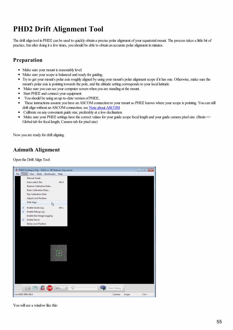
PHD2 Drift Alignment ToolThe drift align tool in PHD2 can be used to quickly obtain a precise polar alignment of your equatorial mount. The process takes a little bit ofpractice, but after doing it a few times, you should be able to obtain an accurate polar alignment in minutes.
Preparation
Make sure your mount is reasonably level.Make sure your scope is balanced and ready for guiding.Try to get your mount's polar axis roughly aligned by using your mount's polar alignment scope if it has one. Otherwise, make sure themount's polar axis is pointing towards the pole, and the altitude setting corresponds to your local latitude. Make sure you can see your computer screen when you are standing at the mount. Start PHD2 and connect your equipment. You should be using an up-to-date version of PHD2.. These instructions assume you have an ASCOM connection to your mount so PHD2 knows where your scope is pointing. You can stilldrift align without an ASCOM connection, see Note about ASCOM. Calibrate on any convenient guide star, preferably at a low declination. Make sure your PHD2 settings have the correct values for your guide scope focal length and your guide camera pixel size. (Brain =>Global tab for focal length, Camera tab for pixel size)
Now you are ready for drift aligning.
Azimuth Alignment
Open the Drift Align Tool:
You will see a window like this:
55
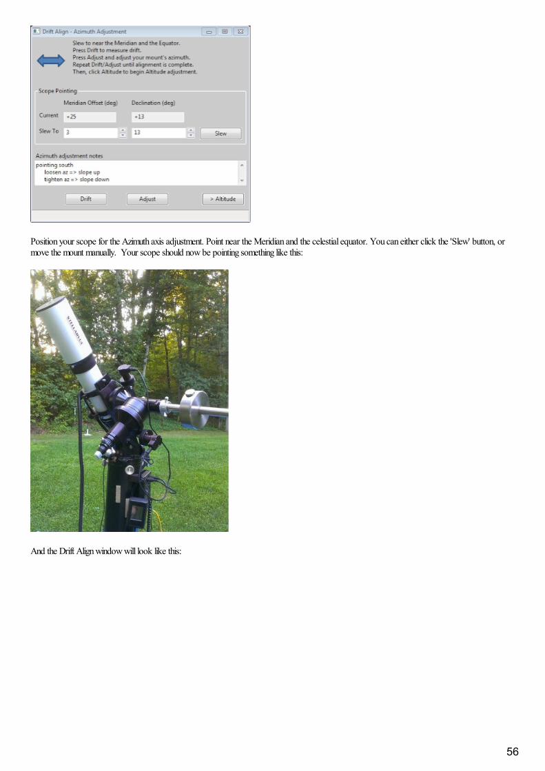
Position your scope for the Azimuth axis adjustment. Point near the Meridian and the celestial equator. You can either click the 'Slew' button, ormove the mount manually. Your scope should now be pointing something like this:
And the Drift Align window will look like this:
56

Notice we are only a few degrees off the meridian ("Meridian offset"), and close to the equator (small value of Declination.)
You are going to alternate between measuring the error ('Drift'), and adjusting the mount ('Adjust'). The rate of declination drift tells us the amountof alignment error. Each adjustment will reduce the error, and you repeat the process as many times as you need to get the error close to zero.
Click 'Drift' to start measuring the declination drift. PHD2 will select a guide star and start guiding. After a few moments you should see somethinglike this:
Pay particular attention to the Declination trend line (Red). At first the Dec trend line will be jumping up and down, but soon the noise should"average out" and the slope of the line will become somewhat stable. When that happens you are ready to adjust the mount's Azimuth.
57
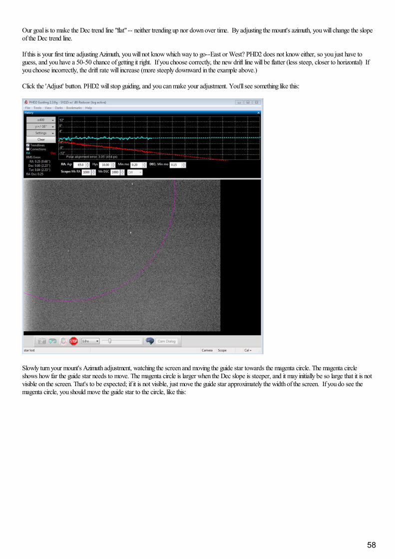
Our goal is to make the Dec trend line "flat" -- neither trending up nor down over time. By adjusting the mount's azimuth, you will change the slopeof the Dec trend line.
If this is your first time adjusting Azimuth, you will not know which way to go--East or West? PHD2 does not know either, so you just have toguess, and you have a 50-50 chance of getting it right. If you choose correctly, the new drift line will be flatter (less steep, closer to horizontal) Ifyou choose incorrectly, the drift rate will increase (more steeply downward in the example above.)
Click the 'Adjust' button. PHD2 will stop guiding, and you can make your adjustment. You'll see something like this:
Slowly turn your mount's Azimuth adjustment, watching the screen and moving the guide star towards the magenta circle. The magenta circleshows how far the guide star needs to move. The magenta circle is larger when the Dec slope is steeper, and it may initially be so large that it is notvisible on the screen. That's to be expected; if it is not visible, just move the guide star approximately the width of the screen. If you do see themagenta circle, you should move the guide star to the circle, like this:
58
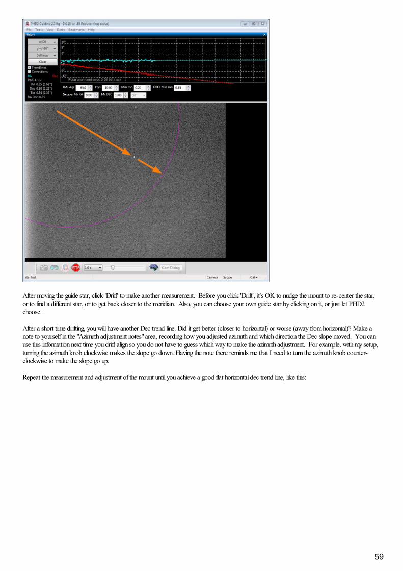
After moving the guide star, click 'Drift' to make another measurement. Before you click 'Drift', it's OK to nudge the mount to re-center the star,or to find a different star, or to get back closer to the meridian. Also, you can choose your own guide star by clicking on it, or just let PHD2choose.
After a short time drifting, you will have another Dec trend line. Did it get better (closer to horizontal) or worse (away from horizontal)? Make anote to yourself in the "Azimuth adjustment notes" area, recording how you adjusted azimuth and which direction the Dec slope moved. You canuse this information next time you drift align so you do not have to guess which way to make the azimuth adjustment. For example, with my setup,turning the azimuth knob clockwise makes the slope go down. Having the note there reminds me that I need to turn the azimuth knob counter-clockwise to make the slope go up.
Repeat the measurement and adjustment of the mount until you achieve a good flat horizontal dec trend line, like this:
59
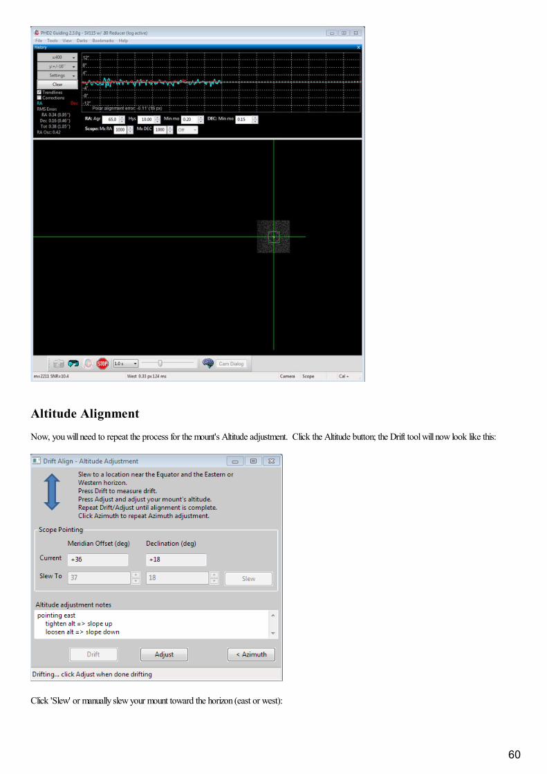
Altitude Alignment
Now, you will need to repeat the process for the mount's Altitude adjustment. Click the Altitude button; the Drift tool will now look like this:
Click 'Slew' or manually slew your mount toward the horizon (east or west):
60

The exact position is not important, but 23-35 degrees above the horizon works well.
Click 'Drift' to start drifting.
Drift until you have a stable Dec slope. Click Adjust, then turn the mount's Altitude adjustment knob. Use your notes recorded in the "Altitudeadjustment notes" area from a previous session to determine which way to turn the knob to move the slope in the desired direction. For example,with my setup I turn the altitude knob clockwise to make the slope go "down".
61
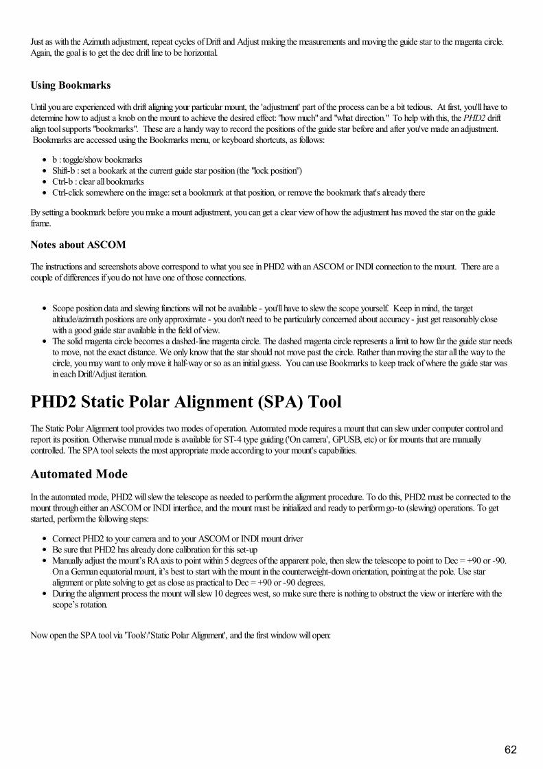
Just as with the Azimuth adjustment, repeat cycles of Drift and Adjust making the measurements and moving the guide star to the magenta circle.Again, the goal is to get the dec drift line to be horizontal.
Using Bookmarks
Until you are experienced with drift aligning your particular mount, the 'adjustment' part of the process can be a bit tedious. At first, you'll have todetermine how to adjust a knob on the mount to achieve the desired effect: "how much" and "what direction." To help with this, the PHD2 driftalign tool supports "bookmarks". These are a handy way to record the positions of the guide star before and after you've made an adjustment. Bookmarks are accessed using the Bookmarks menu, or keyboard shortcuts, as follows:
b : toggle/show bookmarks Shift-b : set a bookark at the current guide star position (the "lock position")Ctrl-b : clear all bookmarks Ctrl-click somewhere on the image: set a bookmark at that position, or remove the bookmark that's already there
By setting a bookmark before you make a mount adjustment, you can get a clear view of how the adjustment has moved the star on the guideframe.
Notes about ASCOM
The instructions and screenshots above correspond to what you see in PHD2 with an ASCOM or INDI connection to the mount. There are acouple of differences if you do not have one of those connections.
Scope position data and slewing functions will not be available - you'll have to slew the scope yourself. Keep in mind, the targetaltitude/azimuth positions are only approximate - you don't need to be particularly concerned about accuracy - just get reasonably closewith a good guide star available in the field of view.The solid magenta circle becomes a dashed-line magenta circle. The dashed magenta circle represents a limit to how far the guide star needsto move, not the exact distance. We only know that the star should not move past the circle. Rather than moving the star all the way to thecircle, you may want to only move it half-way or so as an initial guess. You can use Bookmarks to keep track of where the guide star wasin each Drift/Adjust iteration.
PHD2 Static Polar Alignment (SPA) ToolThe Static Polar Alignment tool provides two modes of operation. Automated mode requires a mount that can slew under computer control andreport its position. Otherwise manual mode is available for ST-4 type guiding ('On camera', GPUSB, etc) or for mounts that are manuallycontrolled. The SPA tool selects the most appropriate mode according to your mount's capabilities.
Automated Mode
In the automated mode, PHD2 will slew the telescope as needed to perform the alignment procedure. To do this, PHD2 must be connected to themount through either an ASCOM or INDI interface, and the mount must be initialized and ready to perform go-to (slewing) operations. To getstarted, perform the following steps:
Connect PHD2 to your camera and to your ASCOM or INDI mount driverBe sure that PHD2 has already done calibration for this set-upManually adjust the mount’s RA axis to point within 5 degrees of the apparent pole, then slew the telescope to point to Dec = +90 or -90.On a German equatorial mount, it’s best to start with the mount in the counterweight-down orientation, pointing at the pole. Use staralignment or plate solving to get as close as practical to Dec = +90 or -90 degrees.During the alignment process the mount will slew 10 degrees west, so make sure there is nothing to obstruct the view or interfere with thescope’s rotation.
Now open the SPA tool via 'Tools'/'Static Polar Alignment', and the first window will open:
62

The PHD2 main display would look like this (southern pole example):
The star map at the top of the SPA window shows the approximate position of the polar stars oriented according to your PHD2 calibration andmount position. You can adjust the ‘Hour Angle’ control or use the ‘Flip Camera’ option to orient the star map to the main display. To pan the star
63
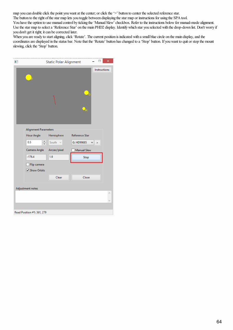
map you can double click the point you want at the center; or click the ‘>’ button to center the selected reference star.The button to the right of the star map lets you toggle between displaying the star map or instructions for using the SPA tool.You have the option to use manual control by ticking the ‘Manual Slew’ checkbox. Refer to the instructions below for manual-mode alignment.Use the star map to select a ‘Reference Star’ on the main PHD2 display. Identify which star you selected with the drop-down list. Don't worry ifyou don't get it right; it can be corrected later.When you are ready to start aligning, click ‘Rotate’. The current position is indicated with a small blue circle on the main display, and thecoordinates are displayed in the status bar. Note that the ‘Rotate’ button has changed to a ‘Stop’ button. If you want to quit or stop the mountslewing, click the ‘Stop’ button.
64
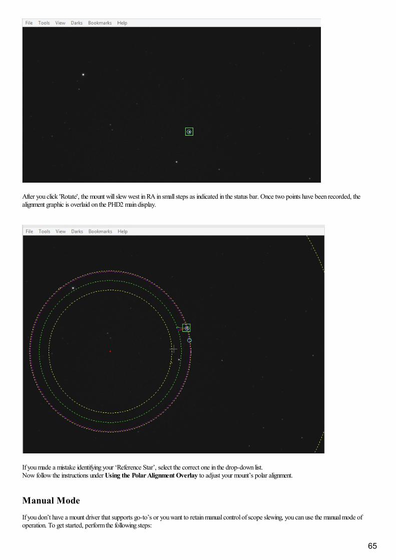
After you click 'Rotate', the mount will slew west in RA in small steps as indicated in the status bar. Once two points have been recorded, thealignment graphic is overlaid on the PHD2 main display.
If you made a mistake identifying your ‘Reference Star’, select the correct one in the drop-down list. Now follow the instructions under Using the Polar Alignment Overlay to adjust your mount’s polar alignment.
Manual Mode
If you don’t have a mount driver that supports go-to’s or you want to retain manual control of scope slewing, you can use the manual mode ofoperation. To get started, perform the following steps:
65
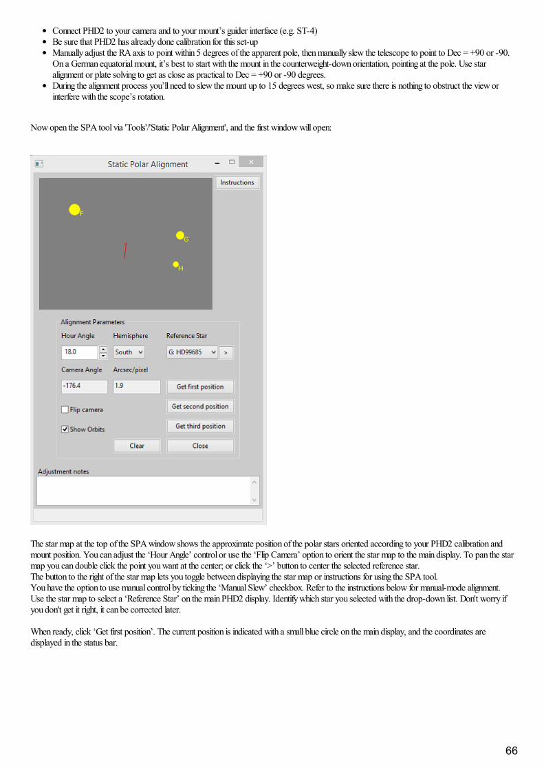
Connect PHD2 to your camera and to your mount’s guider interface (e.g. ST-4)Be sure that PHD2 has already done calibration for this set-upManually adjust the RA axis to point within 5 degrees of the apparent pole, then manually slew the telescope to point to Dec = +90 or -90.On a German equatorial mount, it’s best to start with the mount in the counterweight-down orientation, pointing at the pole. Use staralignment or plate solving to get as close as practical to Dec = +90 or -90 degrees.During the alignment process you’ll need to slew the mount up to 15 degrees west, so make sure there is nothing to obstruct the view orinterfere with the scope’s rotation.
Now open the SPA tool via 'Tools'/'Static Polar Alignment', and the first window will open:
The star map at the top of the SPA window shows the approximate position of the polar stars oriented according to your PHD2 calibration andmount position. You can adjust the ‘Hour Angle’ control or use the ‘Flip Camera’ option to orient the star map to the main display. To pan the starmap you can double click the point you want at the center; or click the ‘>’ button to center the selected reference star.The button to the right of the star map lets you toggle between displaying the star map or instructions for using the SPA tool.You have the option to use manual control by ticking the ‘Manual Slew’ checkbox. Refer to the instructions below for manual-mode alignment.Use the star map to select a ‘Reference Star’ on the main PHD2 display. Identify which star you selected with the drop-down list. Don't worry ifyou don't get it right, it can be corrected later.
When ready, click ‘Get first position’. The current position is indicated with a small blue circle on the main display, and the coordinates aredisplayed in the status bar.
66
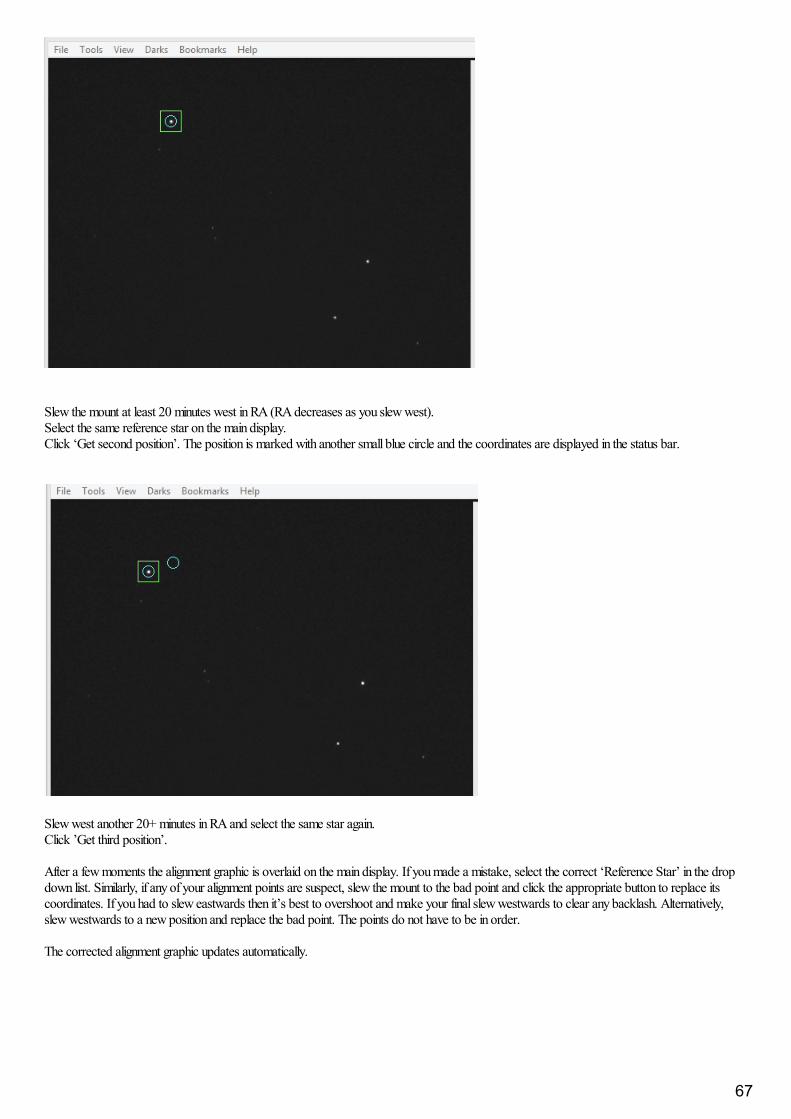
Slew the mount at least 20 minutes west in RA (RA decreases as you slew west). Select the same reference star on the main display. Click ‘Get second position’. The position is marked with another small blue circle and the coordinates are displayed in the status bar.
Slew west another 20+ minutes in RA and select the same star again. Click ’Get third position’.
After a few moments the alignment graphic is overlaid on the main display. If you made a mistake, select the correct ‘Reference Star’ in the dropdown list. Similarly, if any of your alignment points are suspect, slew the mount to the bad point and click the appropriate button to replace itscoordinates. If you had to slew eastwards then it’s best to overshoot and make your final slew westwards to clear any backlash. Alternatively,slew westwards to a new position and replace the bad point. The points do not have to be in order.
The corrected alignment graphic updates automatically.
67
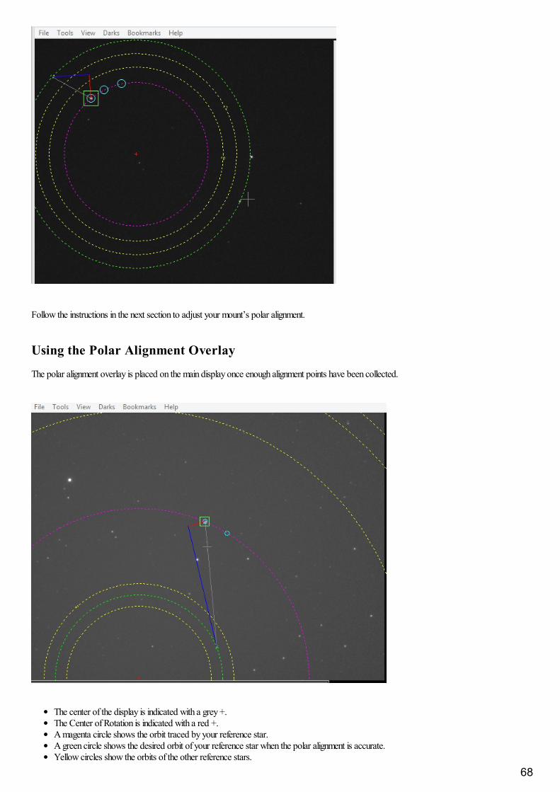
Follow the instructions in the next section to adjust your mount’s polar alignment.
Using the Polar Alignment Overlay
The polar alignment overlay is placed on the main display once enough alignment points have been collected.
The center of the display is indicated with a grey +.The Center of Rotation is indicated with a red +.A magenta circle shows the orbit traced by your reference star.A green circle shows the desired orbit of your reference star when the polar alignment is accurate.Yellow circles show the orbits of the other reference stars.
68
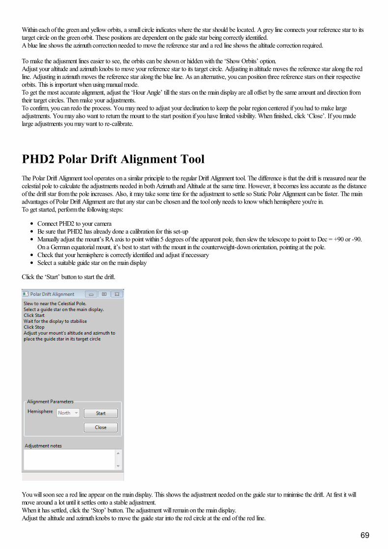
Within each of the green and yellow orbits, a small circle indicates where the star should be located. A grey line connects your reference star to itstarget circle on the green orbit. These positions are dependent on the guide star being correctly identified.A blue line shows the azimuth correction needed to move the reference star and a red line shows the altitude correction required.
To make the adjusment lines easier to see, the orbits can be shown or hidden with the ‘Show Orbits’ option.Adjust your altitude and azimuth knobs to move your reference star to its target circle. Adjusting in altitude moves the reference star along the redline. Adjusting in azimuth moves the reference star along the blue line. As an alternative, you can position three reference stars on their respectiveorbits. This is important when using manual mode.To get the most accurate alignment, adjust the ‘Hour Angle’ till the stars on the main display are all offset by the same amount and direction fromtheir target circles. Then make your adjustments.To confirm, you can redo the process. You may need to adjust your declination to keep the polar region centered if you had to make largeadjustments. You may also want to return the mount to the start position if you have limited visibility. When finished, click ‘Close’. If you madelarge adjustments you may want to re-calibrate.
PHD2 Polar Drift Alignment ToolThe Polar Drift Alignment tool operates on a similar principle to the regular Drift Alignment tool. The difference is that the drift is measured near thecelestial pole to calculate the adjustments needed in both Azimuth and Altitude at the same time. However, it becomes less accurate as the distanceof the drift star from the pole increases. Also, it may take some time for the adjustment to settle so Static Polar Alignment can be faster. The mainadvantages of Polar Drift Alignment are that any star can be chosen and the tool only needs to know which hemisphere you're in.To get started, perform the following steps:
Connect PHD2 to your cameraBe sure that PHD2 has already done a calibration for this set-upManually adjust the mount’s RA axis to point within 5 degrees of the apparent pole, then slew the telescope to point to Dec = +90 or -90.On a German equatorial mount, it’s best to start with the mount in the counterweight-down orientation, pointing at the pole.Check that your hemisphere is correctly identified and adjust if necessarySelect a suitable guide star on the main display
Click the ‘Start’ button to start the drift.
You will soon see a red line appear on the main display. This shows the adjustment needed on the guide star to minimise the drift. At first it willmove around a lot until it settles onto a stable adjustment.When it has settled, click the ‘Stop’ button. The adjustment will remain on the main display.Adjust the altitude and azimuth knobs to move the guide star into the red circle at the end of the red line.
69
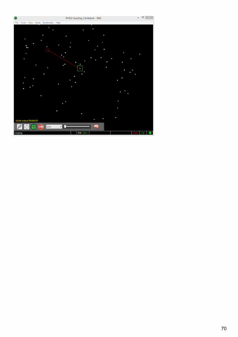
70