Embed Size (px)
Citation preview

English
Phaser 5335Duplex Unit Installation Guide
Thank you for purchasing the duplex unit.This guide is intended for first-time users and gives instructions on installing the product.To ensure safe operation of the printer, be sure to read "Safety Notes" in the ‘User Guide’ before starting the installation.
WARNING• This equipment has been designed to restrict operator access to safe areas only.
Operator access to hazardous areas is restricted with covers or guards, which would require a tool to remove. Never remove these covers or guards.
Important• Before plugging or unplugging the interface cable connector, be sure to switch off the printer or unplug
the power cord from the power outlet. Plugging or unplugging the connector when the printer is on can cause printer failure.
Checking the Package ContentsThe packaging box contains the following items. If you find any items missing, please contact your Customer Support Center or your dealer.
• Duplex unit A • Duplex unit B
• This guide
Part Number: 701P47289 Ver 1.0 December 2007
1
Installation Procedure
1. Switch the power off by pressing the power switch located on the front lower right of the printer to the <O> position.Unplug the power cord from the power outlet and the printer.
2. If paper is loaded in the Tray 1 (Bypass tray), remove the paper.If Tray 1 is not open, open the tray.
3. Open the upper cover.
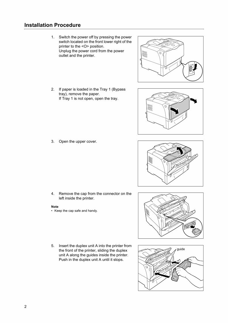
4. Remove the cap from the connector on the left inside the printer.
Note• Keep the cap safe and handy.
5. Insert the duplex unit A into the printer from the front of the printer, sliding the duplex unit A along the guides inside the printer. Push in the duplex unit A until it stops.
guide
2

English
6. Firmly tighten the two screws on both upper front sides of the duplex unit A.
7. Close the upper cover and then Tray 1 (Bypass tray).
8. Pull the front cover release levers on both sides of the printer towards you and open the front cover.
9. Open the top cover.
10. Remove the cap from the connector on the top right of the printer.
Note• Keep the cap safe and handy.
3

11. Align the < > marks on the duplex unit B and the printer, and vertically insert the connector on the duplex unit B into the connector on the printer.When the duplex unit B is securely connected, it is locked.
12. Firmly tighten the screw on top of the duplex unit B.
13. Close the top cover and the front cover.
Important• When closing the front cover, be careful not to get your
fingers caught between (the left, right, top, or bottom edge of) the cover and the printer.
14. Plug in the power cord and switch the power on by pressing the power switch to the <|> position.
The installation is now complete.
Note• You can check whether the duplex unit has been installed correctly by printing out the [Printer Settings]
list. Refer to "Printing the Reports/Lists" in the ‘User Guide’ on how to print the [Printer Settings] list.• After installing the duplex unit, change the accessory configuration on your print driver. For more
information, refer to the online help provided for the print driver.
4

Français
Phaser 5335Guide d'installation de l'unité recto-verso
Nous vous remercions d'avoir choisi cette unité recto-verso.Ce guide est conçu à l'intention des utilisateurs inexpérimentés et fournit des instructions d'installation du produit.Pour assurer l'utilisation en toute sécurité de l'imprimante, veillez à lire les mentions de sécurité du Guide d'utilisation avant de procéder à l'installation.
AVERTISSEMENT• Cet équipement a été conçu pour permettre à l'opérateur d'accéder uniquement aux
zones ne présentant aucun danger. L'accès aux zones dangereuses est restreint par des capots ou protections qu'il est impossible de retirer sans un outil spécifique. Ne retirez jamais ces panneaux ou protections.
Important• Avant de brancher ou de débrancher le connecteur du câble d'interface, veillez à éteindre l'imprimante
ou à débrancher le cordon d'alimentation de la prise électrique. Le branchement ou débranchement de ce connecteur lorsque l'imprimante est sous tension peut provoquer des pannes d'imprimante.
Vérification du contenu de l'emballageLe carton d'emballage doit contenir les éléments suivants : Si l'un de ces éléments est manquant, veuillez contacter le centre de support clientèle ou votre fournisseur.
• Unité recto-verso A • Unité recto-verso B
• Ce guide
Version 1.0 Décembre 2007
5

Procédure d'installation
1. Mettez l'imprimante hors tension en appuyant sur l'interrupteur situé sur la partie inférieure droite de l'imprimante pour le mettre en position <O>.Débranchez le cordon d'alimentation de la prise électrique et de l'imprimante.
2. Si du papier est présent dans le bac 1 (départ manuel), retirez le papier.Si le bac 1 n'est pas déjà ouvert, ouvrez-le.
3. Ouvrez le capot supérieur.
4. Retirez le capuchon du connecteur situé sur le côté gauche à l'intérieur de l'imprimante.
Remarque• Gardez le capuchon à portée de main et dans un
endroit sûr.
5. Insérez l'unité recto-verso A dans l'imprimante en la plaçant à l'avant de l'imprimante et en la faisant glisser le long des guides situés à l'intérieur de l'imprimante. Poussez l'unité recto-verso A jusqu'à ce qu'elle arrive en butée.
guide
6

Français
6. Resserrez fermement les deux vis situées sur les deux côtés supérieurs avant de l'unité recto-verso A.
7. Fermez le capot supérieur et le bac 1 (départ manuel).
8. Ouvrez le panneau avant en tirant vers vous les leviers de dégagement du capot avant situés de chaque côté de l'imprimante.
9. Ouvrez le capot supérieur.
10. Retirez le capuchon du connecteur situé sur la partie supérieure droite de l'imprimante.
Remarque• Gardez le capuchon à portée de main et dans un
endroit sûr.
7

11. Alignez les symboles < > de l'unité recto-verso B sur ceux de l'imprimante et insérez verticalement le connecteur de l'unité recto-verso B dans le connecteur de l'imprimante.Lorsque l'unité recto-verso est connectée correctement, elle est verrouillée.
12. Resserrez fermement la vis située sur la partie supérieure de l'unité recto-verso B.
13. Fermez le capot supérieur et le capot avant.
Important• Lorsque vous fermez le capot avant, prenez soin de
ne pas vous coincer les doigts entre le capot (bord gauche, droit, haut ou bas) et l'imprimante.
14. Branchez le cordon d'alimentation et allumez l'imprimante en mettant l'interrupteur en position <|>.
L'installation est maintenant terminée.
Remarque• Vous pouvez vérifier si l'unité recto-verso est installée correctement en imprimant la liste [Paramètres de
l'imprimante]. Consultez la section consacrée à l'impression des rapports/listes dans le Guide d'utilisation pour savoir comment imprimer la liste [Paramètres de l'imprimante].
• Après avoir installé l'unité recto-verso, changez la configuration des accessoires dans votre pilote d'imprimante. Pour plus d'informations, consultez l'aide en ligne du pilote d'imprimante.
8

Español
Phaser 5335Guía de instalación de la unidad de
impresión a dos carasGracias por comprar la unidad de impresión a dos caras.Esta guía se ha creado para nuevos usuarios e incluye instrucciones para instalar el producto.Para asegurarse de utilizar la impresora de forma segura, no olvide leer las "Notas de seguridad" que aparecen en la ‘Guía del usuario’ antes de comenzar la instalación.
AVISO• Este equipo ha sido diseñado para restringir el acceso del operador únicamente a las
áreas seguras. El acceso del operador a las áreas de peligro se restringe con cubiertas o dispositivos de seguridad, que sólo pueden retirarse con herramientas. Nunca retire estas cubiertas o dispositivos de seguridad.
Importante• Antes de conectar o desconectar el conector del cable de interfaz, asegúrese de apagar la impresora o
desconectar el cable de alimentación del tomacorriente. Si el conector se conecta o desconecta mientras la impresora está encendida, puede producirse un error en la impresora.
Verificación del contenido del paqueteLa caja contiene los siguientes artículos. Si falta alguno de ellos, póngase en contacto con el Centro de asistencia al cliente o el distribuidor de su localidad.
• Unidad de impresión a dos caras A • Unidad de impresión a dos caras B
• Esta guía
Ver. 1.0 Diciembre del 2007
9

Procedimiento de instalación
1. Apague la máquina, pulsando el interruptor de alimentación ubicado al frente de la impresora, en la parte inferior derecha, a la posición <O>.Desenchufe el cable de alimentación del tomacorriente y de la impresora.
2. Si hay papel en la bandeja 1 (bandeja especial), retírelo.Si la bandeja 1 no está abierta, ábrala.
3. Abra la puerta superior.
4. Quite la tapa del conector que está a la izquierda, en el interior de la impresora.
Nota• Guarde esta tapa en un lugar seguro y cercano.
5. Introduzca la unidad de impresión a dos caras A en la impresora por el frente de la impresora, deslizando la unidad por las guías que están en el interior de la impresora. Empuje la unidad de impresión a dos caras A hasta llegar al tope.
Guías
10

Español
6. Apriete firmemente los dos tornillos de la parte superior delantera de la unidad de impresión a dos caras A.
7. Cierre la puerta superior y luego la bandeja 1 (bandeja especial).
8. Tire de las palancas de apertura de la puerta que hay en ambos lados de la impresora hacia usted y abra la puerta frontal.
9. Abra la puerta superior.
10. Quite la tapa del conector que está en la parte superior derecha de la impresora.
Nota• Guarde esta tapa en un lugar seguro y cercano.
11

11. Alinee las marcas < > de la unidad de impresión a dos caras B y la impresora, e introduzca verticalmente el conector de la unidad de impresión a dos caras B en el conector de la impresora.La unidad de impresión a dos caras B quedará sujetada cuando ésta se conecte firmemente.
12. Apriete firmemente el tornillo que hay en la parte superior de la unidad de impresión a dos caras B.
13. Cierre la puerta superior y la puerta frontal.
Importante• Al cerrar la puerta frontal, tenga cuidado de que sus
dedos no queden atrapados entre (el borde izquierdo, derecho, superior o inferior de) la puerta y la impresora.
14. Conecte el cable de alimentación y encienda la máquina, pulsando el interruptor de alimentación a la posición <|>.
Aquí concluye la instalación.
Nota• Puede comprobar si la unidad de impresión a dos caras se ha instalado correctamente, imprimiendo la
lista [Parámetros impresora]. Consulte "Impresión de informes/Listas" en la ‘Guía del usuario’ para averiguar cómo imprimir la lista [Parámetros impresora].
• Después de instalar la unidad de impresión a dos caras, cambie la configuración de accesorios en el controlador de la impresora. Para obtener más información, consulte la ayuda en línea que se proporciona para el controlador de la impresora.
12

Русский
Phaser 5335Руководство по установке блока
двусторонней печатиСпасибо за покупку блока двусторонней печати.Данное руководство предназначено для начинающих пользователей и содержит указания по установке устройства.Для обеспечения безопасной эксплуатации принтера перед началом установки прочтите раздел «Правила техники безопасности» в руководстве пользователя.
ПРЕДУПРЕЖДЕНИЕ• Аппарат спроектирован так, чтобы оператор имел доступ только к безопасным зонам. Доступ к опасным зонам защищен крышками и ограждениями, для открывания которых требуется инструмент. Не снимайте эти крышки и ограждения.
Важная информация• Перед подключением и отключением разъема интерфейсного кабеля выключите принтер или выньте вилку шнура питания из сетевой розетки. Подключение и отключение разъема при выключенном принтере может привести к повреждению аппарата.
Проверка комплекта поставкиДалее перечислено содержимое комплекта поставки. В случае некомплектности обращайтесь в Центр технической поддержки или к дилеру.
• Блок двусторонней печати А • Блок двусторонней печати В
• Руководство (данный документ)
Вер. 1.0, Декабрь 2007 г.
13

Процедура установки
1. Выключите электропитание нажатием выключателя питания, расположенного спереди принтера в нижнем правом углу, в положение <O>.Выньте вилку шнура питания из сетевой розетки и отсоедините шнур от принтера.
2. Если в лоток 1 (обходной) загружена бумага, выньте её.Если лоток 1 закрыт, откройте его.
3. Откройте верхнюю крышку.
4. Снимите заглушку с разъема, расположенного внутри принтера с левой стороны.
Примечание• Уберите заглушку в надежное место рядом с принтером.
5. Вставьте блок двусторонней печати А спереди принтера по внутренним направляющим принтера. Задвиньте блок двусторонней печати А до упора.
руководство
14

Русский
6. Плотно затяните два винта, расположенные по обе стороны вверху блока двусторонней печати А.
7. Закройте верхнюю крышку и лоток 1 (обходной).
8. Потяните на себя рычажки передней крышки, расположенные с обеих сторон принтера, и откройте переднюю крышку.
9. Откройте верхнюю крышку.
10. Снимите заглушку с разъема, расположенного вверху принтера с правой стороны.
Примечание• Уберите заглушку в надежное место рядом с принтером.
15

11. Совместите метки < > на блоке двусторонней печати В и принтере, и вертикально вставьте разъем блока В в разъем принтера.Когда блок двусторонней печати В надежно подсоединен, он должен заблокироваться.
12. Плотно затяните винт вверху блока двусторонней печати В.
13. Закройте верхнюю и переднюю крышки.
Важная информация• При закрывании передней крышки соблюдайте осторожность, чтобы пальцы не попали между крышкой и принтером.
14. Вставьте вилку шнура питания в розетку и включите электропитание нажатием выключателя питания в положение <|>.
Процедура установки завершена.
Примечание• Правильность установки блока двусторонней печати можно проверить, распечатав список
[Настройки принтера]. Описание печати списка [Настройки принтера] см. раздел «Печать отчетов/списков» в руководстве пользователя.
• После установки блока двусторонней печати измените конфигурацию дополнительных устройств в драйвере принтера. Подробнее см. интерактивную справку для драйвера принтера.
16