Embed Size (px)
Citation preview
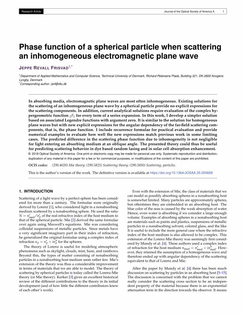
Research Article Journal of the Optical Society of America A 1
Phase function of a spherical particle when scatteringan inhomogeneous electromagnetic plane waveJEPPE REVALL FRISVAD1,*
1Department of Applied Mathematics and Computer Science, Technical University of Denmark, Richard Petersens Plads, Building 321, DK-2800 KongensLyngby, Denmark*Corresponding author: [email protected]
In absorbing media, electromagnetic plane waves are most often inhomogeneous. Existing solutions forthe scattering of an inhomogeneous plane wave by a spherical particle provide no explicit expressions forthe scattering components. In addition, current analytical solutions require evaluation of the complex hy-pergeometric function 2F1 for every term of a series expansion. In this work, I develop a simpler solutionbased on associated Legendre functions with argument zero. It is similar to the solution for homogeneousplane waves but with new explicit expressions for the angular dependency of the far-field scattering com-ponents, that is, the phase function. I include recurrence formulae for practical evaluation and providenumerical examples to evaluate how well the new expressions match previous work in some limitingcases. The predicted difference in the scattering phase function due to inhomogeneity is not negligiblefor light entering an absorbing medium at an oblique angle. The presented theory could thus be usefulfor predicting scattering behavior in dye based random lasing and in solar cell absorption enhancement.© 2018 Optical Society of America. One print or electronic copy may be made for personal use only. Systematic reproduction and distribution,
duplication of any material in this paper for a fee or for commercial purposes, or modifications of the content of this paper are prohibited.
OCIS codes: (290.4020) Mie theory; (290.5825) Scattering theory; (290.5850) Scattering, particles.
This is the author’s version of the work. The definitive version is available at https://doi.org/10.1364/JOSAA.35.000669
1. INTRODUCTION
Scattering of a light wave by a perfect sphere has been consid-ered for more than a century. The formulae were originallyderived by Lorenz [1], who considered light in a nonabsorbingmedium scattered by a nonabsorbing sphere. He used the ratioN = n′med/n′p of the real refractive index of the host medium tothat of the spherical particle. Mie [2] derived the same formulaeover again using Maxwell’s equations. Mie was consideringcolloidal suspensions of metallic particles. Since metals havea very significant imaginary part in their index of refraction,he generalized the original formulae using a complex index ofrefraction np = n′p + in′′p for the spheres.
The theory of Lorenz is useful for modeling atmosphericphenomena such as skylight, clouds, mist, haze, and rainbows.Beyond this, the types of matter consisting of nonabsorbingparticles in a nonabsorbing host medium seem rather few. Mie’sextension of the theory was thus a considerable improvementin terms of materials that we are able to model. The theory ofscattering by spherical particles is today called the Lorenz-Mietheory (or Mie theory). Kerker [3] gives an excellent historicalreview of the different contributions to the theory in its initialdevelopment (and of how little the different contributors knewof each other’s work).
Even with the extension of Mie, the class of materials that wecan model as possibly absorbing spheres in a nonabsorbing hostis somewhat limited. Many particles are approximately spheres,but oftentimes they are embedded in an absorbing host. Theblue color of the seas is caused by the weak absorption of water.Hence, even water is absorbing if we consider a large enoughvolume. Examples of absorbing spheres in a nonabsorbing hostare materials such as paints and plastics, suspensions of metallicparticles in a nonabsorbing solvent, colored glass, and the like.It is useful to include the more general case where the refractiveindex of the host medium is also allowed to be complex. Thisextension of the Lorenz-Mie theory was seemingly first consid-ered by Mundy et al. [4]. These authors used a complex indexof refraction for the host medium nmed = n′med + in′′med. How-ever, they retained the assumption of a homogeneous wave andtherefore ended up with angular dependency of the scatteringequivalent to that of Lorenz and Mie.
After the paper by Mundy et al. [4] there has been muchdiscussion on scattering by particles in an absorbing host [5–15].The discussion is concerned with the problem that we cannotreally consider the scattering cross section to be an indepen-dent property of the material because there is an exponentialattenuation term in the direction towards the observer. It means
Research Article Journal of the Optical Society of America A 2
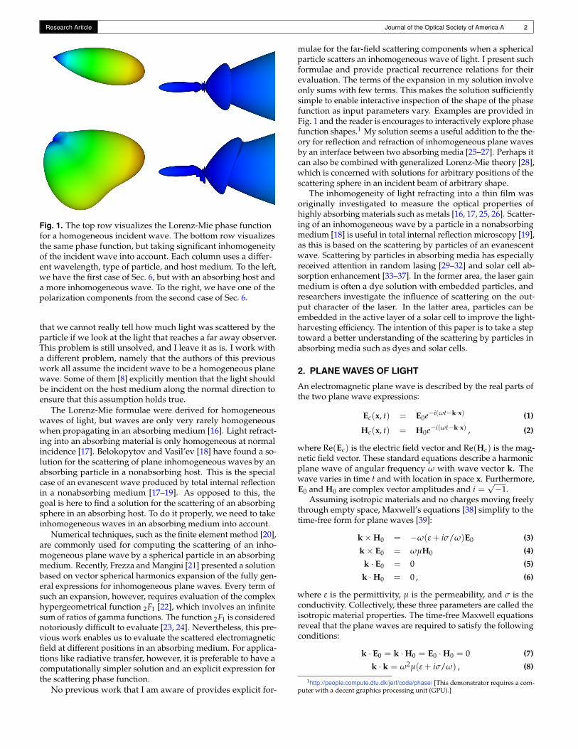
Fig. 1. The top row visualizes the Lorenz-Mie phase functionfor a homogeneous incident wave. The bottom row visualizesthe same phase function, but taking significant inhomogeneityof the incident wave into account. Each column uses a differ-ent wavelength, type of particle, and host medium. To the left,we have the first case of Sec. 6, but with an absorbing host anda more inhomogeneous wave. To the right, we have one of thepolarization components from the second case of Sec. 6.
that we cannot really tell how much light was scattered by theparticle if we look at the light that reaches a far away observer.This problem is still unsolved, and I leave it as is. I work witha different problem, namely that the authors of this previouswork all assume the incident wave to be a homogeneous planewave. Some of them [8] explicitly mention that the light shouldbe incident on the host medium along the normal direction toensure that this assumption holds true.
The Lorenz-Mie formulae were derived for homogeneouswaves of light, but waves are only very rarely homogeneouswhen propagating in an absorbing medium [16]. Light refract-ing into an absorbing material is only homogeneous at normalincidence [17]. Belokopytov and Vasil’ev [18] have found a so-lution for the scattering of plane inhomogeneous waves by anabsorbing particle in a nonabsorbing host. This is the specialcase of an evanescent wave produced by total internal reflectionin a nonabsorbing medium [17–19]. As opposed to this, thegoal is here to find a solution for the scattering of an absorbingsphere in an absorbing host. To do it properly, we need to takeinhomogeneous waves in an absorbing medium into account.
Numerical techniques, such as the finite element method [20],are commonly used for computing the scattering of an inho-mogeneous plane wave by a spherical particle in an absorbingmedium. Recently, Frezza and Mangini [21] presented a solutionbased on vector spherical harmonics expansion of the fully gen-eral expressions for inhomogeneous plane waves. Every term ofsuch an expansion, however, requires evaluation of the complexhypergeometrical function 2F1 [22], which involves an infinitesum of ratios of gamma functions. The function 2F1 is considerednotoriously difficult to evaluate [23, 24]. Nevertheless, this pre-vious work enables us to evaluate the scattered electromagneticfield at different positions in an absorbing medium. For applica-tions like radiative transfer, however, it is preferable to have acomputationally simpler solution and an explicit expression forthe scattering phase function.
No previous work that I am aware of provides explicit for-
mulae for the far-field scattering components when a sphericalparticle scatters an inhomogeneous wave of light. I present suchformulae and provide practical recurrence relations for theirevaluation. The terms of the expansion in my solution involveonly sums with few terms. This makes the solution sufficientlysimple to enable interactive inspection of the shape of the phasefunction as input parameters vary. Examples are provided inFig. 1 and the reader is encourages to interactively explore phasefunction shapes.1 My solution seems a useful addition to the the-ory for reflection and refraction of inhomogeneous plane wavesby an interface between two absorbing media [25–27]. Perhaps itcan also be combined with generalized Lorenz-Mie theory [28],which is concerned with solutions for arbitrary positions of thescattering sphere in an incident beam of arbitrary shape.
The inhomogeneity of light refracting into a thin film wasoriginally investigated to measure the optical properties ofhighly absorbing materials such as metals [16, 17, 25, 26]. Scatter-ing of an inhomogeneous wave by a particle in a nonabsorbingmedium [18] is useful in total internal reflection microscopy [19],as this is based on the scattering by particles of an evanescentwave. Scattering by particles in absorbing media has especiallyreceived attention in random lasing [29–32] and solar cell ab-sorption enhancement [33–37]. In the former area, the laser gainmedium is often a dye solution with embedded particles, andresearchers investigate the influence of scattering on the out-put character of the laser. In the latter area, particles can beembedded in the active layer of a solar cell to improve the light-harvesting efficiency. The intention of this paper is to take a steptoward a better understanding of the scattering by particles inabsorbing media such as dyes and solar cells.
2. PLANE WAVES OF LIGHT
An electromagnetic plane wave is described by the real parts ofthe two plane wave expressions:
Ec(x, t) = E0e−i(ωt−k·x) (1)
Hc(x, t) = H0e−i(ωt−k·x) , (2)
where Re(Ec) is the electric field vector and Re(Hc) is the mag-netic field vector. These standard equations describe a harmonicplane wave of angular frequency ω with wave vector k. Thewave varies in time t and with location in space x. Furthermore,E0 and H0 are complex vector amplitudes and i =
√−1.
Assuming isotropic materials and no charges moving freelythrough empty space, Maxwell’s equations [38] simplify to thetime-free form for plane waves [39]:
k×H0 = −ω(ε + iσ/ω)E0 (3)
k× E0 = ωµH0 (4)
k · E0 = 0 (5)
k ·H0 = 0 , (6)
where ε is the permittivity, µ is the permeability, and σ is theconductivity. Collectively, these three parameters are called theisotropic material properties. The time-free Maxwell equationsreveal that the plane waves are required to satisfy the followingconditions:
k · E0 = k ·H0 = E0 ·H0 = 0 (7)
k · k = ω2µ(ε + iσ/ω) , (8)
1http://people.compute.dtu.dk/jerf/code/phase/ [This demonstrator requires a com-puter with a decent graphics processing unit (GPU).]

Research Article Journal of the Optical Society of America A 3
where all the vectors may be complex and εc = ε+ iσ/ω is some-times called the complex permittivity (or the complex dielectricconstant). The latter equation is particularly interesting as itdescribes the relation between material and wave propagation.
Let us take a look at the real and imaginary parts of the wavevector k. We write
k = k′ + ik′′ = k′~s ′ + ik′′~s ′′ ,
where k′ = |k′| and k′′ = |k′′| such that ~s ′ and ~s ′′ are unitvectors in the directions of the real and imaginary parts of thewave vector, respectively. If the real part of the wave vectork′ is parallel to the imaginary part k′′, the wave is said to behomogeneous. Otherwise, it is inhomogeneous. Of course, k′′ = 0is parallel to any vector, why a wave is homogeneous if k isreal-valued. If k is complex, the exponential term of the planewave expressions (1–2) is as follows
eik·x = eik′·xe−k′′·x .
Here, we may observe that k′ is the vector normal to the surfaceof constant phase and k′′ is normal to the surface of constant am-plitude. The phase velocity is then v = ω/k′ and the amplitudeis damped (or decays) in the direction~s ′′ at the rate k′′. Thus,we have an inhomogeneous wave whenever the damping of thewave is not aligned with its direction of propagation.
The rule for propagation of plane waves in an isotropicmedium (8) indicates the convenience of a phenomenologicalquantity defined by
n = n′ + in′′ = c√
µ(ε + iσ/ω) . (9)
This is the (complex) index of refraction, or refractive index.Multiplication by c, the speed of light in vacuo, ensures that nis a unitless quantity. The index of refraction nicely collects thematerial properties and is a quantity measured as one of the keyoptical properties of materials.
The energy of the field is given by the magnitude of thePoynting vector S [40]. For isotropic materials, we have
|S| = ε0c2µ|Re(Ec)× Re(Hc)| ,
where ε0 is the electric constant (also called the vacuum permit-tivity). The factor ε0c2µ is the relative permeability, which isone if the material is not magnetic. Inserting the plane waveexpressions (1–2), we get
|S| = ε0c2µ e−2k′′~s ′′·x
×∣∣∣Re(E0e−i(ωt−k′·x))× Re(H0e−i(ωt−k′·x))
∣∣∣ .
Since the exponential terms which involve ωt and k′ · x are onlyoscillations, it follows that 2k′′ is the exponential attenuation ofthe energy flux as the wave propagates through the material.This attenuation is called the absorption coefficient and it is oftendenoted by the symbol µa or σa (these should not be confusedwith the permeability µ or the conductivity σ).
The direction of the energy flow in the electromagnetic fieldis generally considered to be the time average of the Poyntingvector over a period of oscillation T = 2π/ω. This is [39]
Savg =ε0c2µ
2Re(Ec ×H∗c ) , (10)
where the asterisk ∗ denotes the complex conjugate.
y
x
z
φ
θ
forw
ard d
irec
tion
scattering plane
particle
r
observer
incident light
Fig. 2. Scattering by a particle.
3. SCATTERING BY A PARTICLE
Consider a particle in an electromagnetic field. To describethe effect, we split the field in two contributions: an incidentfield (Ei, Hi) and a scattered field (Es, Hs). The sum of the twocontributions makes up the total electromagnetic field:
Ec = Ei + Es , Hc = Hi + Hs .
Inserting in Eq. (10) to find the total time-averaged Poyntingvector, we get [39]
Savg = Si + Ss + Sext ,
where Si and Ss describe the incident and scattered fields, eachwith an equation as Eq. (10), but with i or s as subscript insteadof c. The term Sext describes the interaction of the two fields.
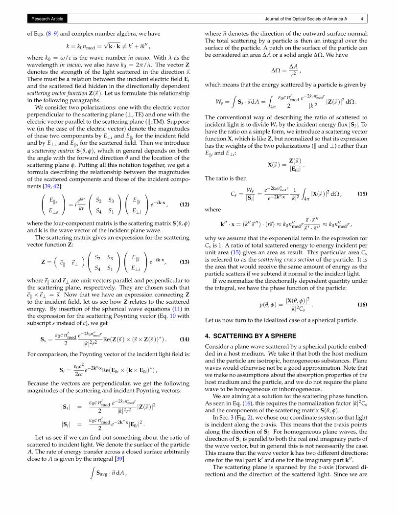
To get an idea about the directions of the different vectors,we introduce a coordinate system; see Fig. 2. The direction ofthe incident light (that is, the direction of Si) defines the axisof incidence. Let us orient our coordinate system so that it hasorigin inside the particle and z-axis along the axis of incidence.The z-axis is then the forward direction. Together the forwarddirection and the direction in which we consider the scatteredlight define the scattering plane. If the two directions are parallel,we may choose any plane containing the axis of incidence. Inthis setting, a spherical coordinate system (r, θ, φ) is orientedsuch that θ is the angle between the forward direction and thescattered direction, while φ is the angle between the x-axis andthe scattering plane. This description of the setup follows thatof Bohren and Huffman [39] (Sec. 3.2).
At a large distance from the particle (in the far field) thescattered field may be expressed as a spherical wave [39, 41]:
Es(x) = ieikr
krZ(~s ) , Hs(x) =
kωµ
ieikr
kr~s× Z(~s ) , (11)
where x = r~s such that r is the distance to the observer and~sis the direction toward the observer, while ω is the angular fre-quency, k is the (complex) wave number, and µ is the permeabil-ity of the medium surrounding the particle. As a consequence
Research Article Journal of the Optical Society of America A 4
of Eqs. (8–9) and complex number algebra, we have
k = k0nmed =√
k · k 6= k′ + ik′′ ,
where k0 = ω/c is the wave number in vacuo. With λ as thewavelength in vacuo, we also have k0 = 2π/λ. The vector Zdenotes the strength of the light scattered in the direction ~s.There must be a relation between the incident electric field Eiand the scattered field hidden in the directionally dependentscattering vector function Z(~s ). Let us formulate this relationshipin the following paragraphs.
We consider two polarizations: one with the electric vectorperpendicular to the scattering plane (⊥, TE) and one with theelectric vector parallel to the scattering plane (‖, TM). Supposewe (in the case of the electric vector) denote the magnitudesof these two components by E⊥i and E‖i for the incident fieldand by E⊥s and E‖s for the scattered field. Then we introducea scattering matrix S(θ, φ), which in general depends on boththe angle with the forward direction θ and the location of thescattering plane φ. Putting all this notation together, we get aformula describing the relationship between the magnitudesof the scattered components and those of the incident compo-nents [39, 42]: E‖s
E⊥s
= ieikr
kr
S2 S3
S4 S1
E‖i
E⊥i
e−ik·x , (12)
where the four-component matrix is the scattering matrix S(θ, φ)and k is the wave vector of the incident plane wave.
The scattering matrix gives an expression for the scatteringvector function Z:
Z =(~e‖ ~e⊥
) S2 S3
S4 S1
E‖i
E⊥i
e−ik·x, (13)
where~e‖ and~e⊥ are unit vectors parallel and perpendicular tothe scattering plane, respectively. They are chosen such that~e‖ ×~e⊥ = ~s. Now that we have an expression connecting Zto the incident field, let us see how Z relates to the scatteredenergy. By insertion of the spherical wave equations (11) inthe expression for the scattering Poynting vector (Eq. 10 withsubscript s instead of c), we get
Ss =ε0c n′med
2e−2k0n′′medr
|k|2r2 Re(Z(~s )× (~s× Z(~s ))∗) . (14)
For comparison, the Poynting vector of the incident light field is:
Si =ε0c2
2ωe−2k′′·xRe(E0i × (k× E0i)
∗) ,
Because the vectors are perpendicular, we get the followingmagnitudes of the scattering and incident Poynting vectors:
|Ss| =ε0c n′med
2e−2k0n′′medr
|k|2r2 |Z(~s )|2
|Si| =ε0c n′med
2e−2k′′·x|E0i|2 .
Let us see if we can find out something about the ratio ofscattered to incident light. We denote the surface of the particleA. The rate of energy transfer across a closed surface arbitrarilyclose to A is given by the integral [39]∫
Savg ·~n dA ,
where ~n denotes the direction of the outward surface normal.The total scattering by a particle is then an integral over thesurface of the particle. A patch on the surface of the particle canbe considered an area ∆A or a solid angle ∆Ω. We have
∆Ω =∆Ar2 ,
which means that the energy scattered by a particle is given by
Ws =∫
Ss ·~s dA =∫
4π
ε0c n′med2
e−2k0n′′medr
|k|2 |Z(~s )|2 dΩ .
The conventional way of describing the ratio of scattered toincident light is to divide Ws by the incident energy flux |Si|. Tohave the ratio on a simple form, we introduce a scattering vectorfunction X, which is like Z, but normalized so that its expressionhas the weights of the two polarizations (‖ and ⊥) rather thanE‖i and E⊥i:
X(~s ) =Z(~s )|E0i|
.
The ratio is then
Cs =Ws
|Si|=
e−2k0n′′medr
e−2k′′·x1|k|2
∫4π|X(~s )|2 dΩ , (15)
where
k′′ · x = (k′′~s ′′) · (r~s) ≈ k0n′′medr~s ·~s ′′~s ′ ·~s ′′ ≈ k0n′′medr ,
why we assume that the exponential term in the expression forCs is 1. A ratio of total scattered energy to energy incident perunit area (15) gives an area as result. This particular area Csis referred to as the scattering cross section of the particle. It isthe area that would receive the same amount of energy as theparticle scatters if we subtend it normal to the incident light.
If we normalize the directionally dependent quantity underthe integral, we have the phase function of the particle:
p(θ, φ) =|X(θ, φ)|2|k|2Cs
. (16)
Let us now turn to the idealized case of a spherical particle.
4. SCATTERING BY A SPHERE
Consider a plane wave scattered by a spherical particle embed-ded in a host medium. We take it that both the host mediumand the particle are isotropic, homogeneous substances. Planewaves would otherwise not be a good approximation. Note thatwe make no assumptions about the absorption properties of thehost medium and the particle, and we do not require the planewave to be homogeneous or inhomogeneous.
We are aiming at a solution for the scattering phase function.As seen in Eq. (16), this requires the normalization factor |k|2Csand the components of the scattering matrix S(θ, φ).
In Sec. 3 (Fig. 2), we chose our coordinate system so that lightis incident along the z-axis. This means that the z-axis pointsalong the direction of Si. For homogeneous plane waves, thedirection of Si is parallel to both the real and imaginary parts ofthe wave vector, but in general this is not necessarily the case.This means that the wave vector k has two different directions:one for the real part k′ and one for the imaginary part k′′.
The scattering plane is spanned by the z-axis (forward di-rection) and the direction of the scattered light. Since we are

Research Article Journal of the Optical Society of America A 5
z
θ
forward direction
incident light
scattering plane
particle
r
observer
α
E
E
i||
i⊥
y
x
k^
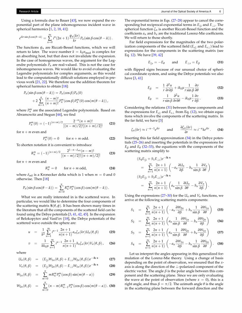
Fig. 3. Scattering by a spherical particle in an absorbing host.
working with a sphere, it is of no consequence with respect toparticle geometry which way we choose to orient the x and yaxes of the coordinate system. We are therefore always allowedto perform a change of basis and choose new directions for the xand y axes. Suppose we choose for any point of observation toalign the yz-plane with the scattering plane through a change ofbasis. We can then find the coordinates of the vectors in the newbasis through projection. In this coordinate system, where theyz-plane is aligned with the scattering plane, it is convenient tospecify an arbitrary incident plane wave by
Ei = E0ie−i(ωt−kx x)ei(kyy+kzz) . (17)
We can think of it as a wave with wave vector k = (0, ky, kz)and amplitude that varies in time and with the location alongthe x-axis. Note that this wave vector corresponds exactly to theprojection of an arbitrary wave vector on the scattering planespanned by the forward direction and the direction toward theobserver. Note also that, in the end, we are only interested inevaluating this wave at the point of observation, where x = 0with our particular choice of basis.
Electromagnetic waves are transverse (due to Maxwell’s equa-tions). Any inhomogeneous transverse plane wave can be de-composed into a transverse electric wave (TE) and a transversemagnetic (TM) wave [26]. We now decompose our incidentwave in this way. As before, we identify TE components with⊥-polarized components and TM components with ‖-polarizedcomponents. The ⊥-polarized component of the electric fieldvector is by definition perpendicular to the scattering plane. The‖-polarized component lies in the scattering plane. We have
Ei = E⊥i~ex + E‖i(a~ey + b~ez) , (18)
where ~ex, ~ey, and ~ez are unit vectors in the directions of thecoordinate axes, E⊥i and E‖i are complex magnitudes of the twopolarization components of Ei, and a and b are the directioncosines of E‖i in the y and z directions, respectively. See Fig. 3.For a homogeneous wave, the direction of E‖i would also beperpendicular to the z-axis, but this is not true in general.
The direction cosines a and b are given by
a = Ey‖i/E‖i and b = Ez‖i/E‖i .
Using that the ‖-polarized component is also transverse mag-netic (TM), we have
Hy‖i = Hz‖i = 0 and Hx‖i = H‖i =√
H‖i ·H‖i .
Inserting this in Eq. (3) and considering the magnitude of the(complex) wave vector (8), we obtain
kz H‖i = −k2
ωµEy‖i and ky H‖i =
k2
ωµEz‖i
from which the following expressions appear:
a = − kzωµ
k2
H‖iE‖i
, b =kyωµ
k2
H‖iE‖i
.
The ratio of the amplitude magnitudes of the (complex) electricand magnetic vectors is obtained from Eqs. (4–5):√
(k× E‖i) · (k× E‖i) = kE‖i = ωµH‖i .
Insertion leads to
a = − kz
k0nmed= − cos α , b =
ky
k0nmed= sin α , (19)
where α is a complex angle denoting the direction of the wavevector in the scattering plane (Fig. 3). In the following, I use aGreek letter with a hat for complex angles.
The structure of the electric vector of the incident wave (17)is quite different from the case of a homogeneous wave, whereonly one spatial coordinate is left in the exponential. For theinhomogeneous wave the scattering is not axially symmetric aroundthe forward direction. This is counterintuitive as the geometry ofthe scatterer is perfectly symmetric. The inhomogeneity of thewave is enough to break the symmetry. As a consequence, wecan use only part of the results of Lorenz and Mie (and manyothers) for inhomogeneous waves. To find a solution, we lookto the work of Belokopytov and Vasil’ev [18].
Suppose we introduce the following slightly unusual set ofspherical coordinates:
x = r cos β
y = r sin β sin θ
z = r sin β cos θ ,
where the x-axis is the polar axis such that the scattering planeis given by sin β = 1 and the forward direction when also θ = 0.The angle θ is shown in Fig. 3. With these spherical coordinates,the expression for our incident field is
Ei = E0ie−i(ωt−kx x)eir(ky sin β sin θ+kz sin β cos θ) .
Using the complex angle α, we can also write it as
Ei = E0ie−i(ωt−kx x)eikr sin β(sin α sin θ+cos α cos θ)
= E0ie−i(ωt−kx x)eikr sin β cos(θ−α) . (20)
This is very close to the form of incident wave for which Be-lokopytov and Vasil’ev found a solution [18]. The generalizationis in the definition of α (which is purely imaginary in their treat-ment). For an inhomogeneous wave, k′ and k′′ are not paralleland a nonabsorbing medium has k · k = k2
0n2med to be a real
number. This can be fulfilled by having kz real and ky purelyimaginary, and then the structure of our incident wave becomesequivalent to the one addressed by Belokopytov and Vasil’ev.
Research Article Journal of the Optical Society of America A 6
Using a formula due to Bauer [43], we now expand the ex-ponential part of the plane inhomogeneous incident wave inspherical harmonics [1, 2, 18, 41]:
eikr sin β cos(θ−α) =∞
∑n=0
in(2n + 1)ψn(kr)
krPn(sin β cos(θ − α)) .
The functions ψn are Riccati-Bessel functions, which we willreturn to later. The wave number k = k0nmed is complex foran absorbing host, but that does not invalidate the expansion.In the case of homogeneous waves, the argument for the Leg-endre polynomials Pn are real-valued. This is not the case forinhomogeneous waves. We would like to avoid evaluating theLegendre polynomials for complex arguments, as this wouldlead to the computationally difficult solutions employed in pre-vious work [21, 22]. We therefore use the addition theorem forspherical harmoics to obtain [18]:
Pn(sin β cos(θ − α)) = Pn(cos β)Pn(0)
+ 2n
∑m=1
(n−m)!(n + m)!
Pmn (cos β)Pm
n (0) cos(m(θ − α)) ,
where Pmn are the associated Legendre polynomials. Based on
Abramowitz and Stegun [44], we find
Pmn (0) = (−1)(n+m)/2 2−n(n + m)!
[(n−m)/2]![(n + m)/2]!(21)
for n + m even and
Pmn (0) = 0 for n + m odd. (22)
To shorten notation it is convenient to introduce
Rmn = (−1)(n+m)/2 21−n−δm0 (n−m)!
[(n−m)/2]![(n + m)/2]!(23)
for n + m even and
Rmn = 0 for n + m odd, (24)
where δm0 is a Kronecker delta which is 1 when m = 0 and 0otherwise. Then [18]
Pn(sin β cos(θ − α)) =n
∑m=0
Rmn Pm
n (cos β) cos(m(θ − α)) .
What we are really interested in is the scattered wave. Inparticular, we would like to determine the four components ofthe scattering matrix S(θ, φ). It has been shown many times inthe literature that all the components of the scattered field can befound using the Debye potentials [3, 41, 42, 45]. In the expansionof Belokopytov and Vasil’ev [18], the Debye potentials of thescattered wave outside the sphere are:
u =1k2
∞
∑n=1
in−1 2n + 1n(n + 1)
anζn(kr)Un(θ, β) (25)
v =1
kk0µ
∞
∑n=1
in−1 2n + 1n(n + 1)
bnζn(kr)Vn(θ, β) , (26)
where
Un(θ, β) = (E‖iW1n(θ, β) + E⊥iW2n(θ, β))e−ik·x (27)
Vn(θ, β) = (E‖iW2n(θ, β)− E⊥iW1n(θ, β))e−ik·x (28)
W1n(θ, β) =n
∑m=0
mRmn Pm
n (cos β) sin(m(θ − α)) (29)
W2n(θ, β) =n
∑m=0
(n−m)Rmn−1Pm
n (cos β) cos(m(θ − α)) . (30)
The exponential terms in Eqs. (27–28) appear to cancel the corre-sponding but reciprocal exponential terms in E‖i and E⊥i. Thespherical function ζn is another Riccati-Bessel function and thecoefficients an and bn are the traditional Lorenz-Mie coefficients.We will return to those shortly.
Far field expressions for the magnitudes of the two polar-ization components of the scattered field (Es‖ and Es⊥) lead toexpressions for the components in the scattering matrix (seeEq. 12). We have [39, 42]
E‖s = −Eθ and E⊥s = Eβ (31)
with flipped signs because of our unusual choice of spheri-cal coordinate system, and using the Debye potentials we alsohave [3, 41]
Eβ =1r
∂2u∂r∂β
+ ik0µ1
r sin β
∂v∂θ
(32)
Eθ =1
r sin β
∂2u∂r∂θ
− ik0µ1r
∂v∂β
. (33)
Considering the relations (31) between these components andthe expressions for Es‖ and Es⊥ from Eq. (12), we obtain equa-tions which involve the components of the scattering matrix. Inthe far field, we have [3]
ζn(kr) ≈ i−n−1eikr and∂ζn(kr)
∂r≈ i−nkeikr . (34)
Inserting this far field approximation (34) in the Debye poten-tials (25–26) and inserting the potentials in the expressions forEβ and Eθ (32–33), the equations with the components of thescattering matrix simplify to
(S4E‖i + S1E⊥i)e−ik·x
=∞
∑n=1
2n + 1n(n + 1)
(−an
∂Un
∂β− bn
1sin β
∂Vn
∂θ
)(S2E‖i + S3E⊥i)e
−ik·x
=∞
∑n=1
2n + 1n(n + 1)
(an
1sin β
∂Un
∂θ− bn
∂Vn
∂β
).
Using the expressions (27–30) for the Un and Vn functions, wearrive at the following scattering matrix components:
S1 =∞
∑n=1
2n + 1n(n + 1)
(−an
∂W2n∂β
+ bn1
sin β
∂W1n∂θ
)(35)
S2 =∞
∑n=1
2n + 1n(n + 1)
(an
1sin β
∂W1n∂θ− bn
∂W2n∂β
)(36)
S3 =∞
∑n=1
2n + 1n(n + 1)
(an
1sin β
∂W2n∂θ
+ bn∂W1n
∂β
)(37)
S4 =∞
∑n=1
2n + 1n(n + 1)
(−an
∂W1n∂β− bn
1sin β
∂W2n∂θ
). (38)
Let us interpret the angles appearing in this generalized for-mulation of the Lorenz-Mie theory. Using a change of basisdepending on the point of observation, we ensured that the x-axis is along the direction of the ⊥-polarized component of theelectric vector. The angle β is the polar angle between this com-ponent and the scattering plane. Since we are only evaluatingthe wave at the point of observation (where x = 0), this is aright angle, and thus β = π/2. The azimuth angle θ is the anglein the scattering plane between the forward direction and the
Research Article Journal of the Optical Society of America A 7
direction of the scattered light. This means that θ is the standardscattering angle. Another angle in the formulae is the complexangle α. It is a measure of the inhomogeneity of the incidentwave, and it is given by the direction cosines in the scatteringplane of the wave vector k of the incident light (Eq. 19).
It should be mentioned that for a homogeneous wave, weget kz = k and ky = 0, and then α = 0. This simplifies the struc-ture of the exponential term in the expression for the incidentwave, and we get the components of the scattering matrix in thecommonly available form [1–3, 42]:
S1(θ) =∞
∑n=1
2n + 1n(n + 1)
(anπn(cos θ) + bnτn(cos θ)) (39)
S2(θ) =∞
∑n=1
2n + 1n(n + 1)
(anτn(cos θ) + bnπn(cos θ)) , (40)
where the functions πn and τn are related to the Legendre poly-nomials Pn as follows:
πn(cos θ) =P1
n(cos θ)
sin θ=
dPn(cos θ)
d(cos θ)(41)
τn(cos θ) =dP1
n(cos θ)
dθ
= cos θ πn(cos θ)− sin2 θdπn(cos θ)
d(cos θ). (42)
Their numeric evaluation can be found in standard referenceson Lorenz-Mie theory [39, 46].
It remains in this discussion of scattering by a spherical par-ticle to give expressions for the Lorenz-Mie coefficients an andbn. In the far field, they are given by the same formulae thatLorenz [1] derived more than a century ago, only now the refrac-tive indices are complex:
an =nmedψ′n(y)ψn(x)− npψn(y)ψ′n(x)nmedψ′n(y)ζn(x)− npψn(y)ζ ′n(x)
(43)
bn =npψ′n(y)ψn(x)− nmedψn(y)ψ′n(x)npψ′n(y)ζn(x)− nmedψn(y)ζ ′n(x)
, (44)
where the primes ′ denote derivative. The Riccati-Bessel func-tions ψn(z) and ζn(z) are related to the spherical Bessel functionsjn(z) and yn(z) as follows:
ψn(z) = zjn(z)ζn(z) = z(jn(z) + iyn(z)) .
One should use the complex conjugate of ζn if the time depen-dence for the wave had been taken to be eiωt instead of e−iωt.The argument z is an arbitrary complex number, the arguments xand y used for the Lorenz-Mie coefficients are related to particleand host media as follows:
x =2πrnmed
λand y =
2πrnp
λ,
where λ is the wavelength in vacuo and r is the radius of thespherical particle.
When computers came around, it turned out to be quite diffi-cult to find a numerically stable way of evaluating the sphericalfunctions ψn and ζn for complex arguments. Eventually, thenumerical difficulties were solved for complex y [46–48]. Thisis sufficient for the traditional Lorenz-Mie theory with a nonab-sorbing host medium. When people started considering spheresin an absorbing host, starting with Mundy et al. [4], it became
necessary to find a robust way of evaluating the Lorenz-Miecoefficients for complex x as well. A robust evaluation schemehas been proposed by Frisvad et al. [49].
To complete the phase function solution, we still miss thenormalization factor |k|2Cs and the calculation of the complexangle α by means of projection. With the Lorenz-Mie coefficients,we can find the normalization factor for the phase function us-ing [39]
|k|2Cs = 2π∞
∑n=1
(2n + 1)(|an|2 + |bn|2) .
Suppose we let ki denote the arbitrary wave vector of the inci-dent field before projection to the scattering plane. The projectedwave vector is then given by
k = ki −ki · (Si ×~s)|Si ×~s|2
Si ×~s (45)
with k = ki if |Si ×~s| = 0. After this projection, we can findthe complex angle α using dot products and arcus cosine forcomplex numbers
α = cos−1 Si · k|Si|√
k · k.
In this setting, we can calculate~s from the spherical coordinatesθ and φ if we want angles as arguments for the phase function.
5. SIMPLIFICATION
Given that we always have β = π/2, we should try to simplifythe solution presented in Equations 35–38. What we are inter-ested in is the partial derivatives of the functions W1n and W2n(Equations 29–30). This means that we need the derivatives
ddθ
(sin(m(θ − α)) = m cos(m(θ − α))
ddθ
(cos(m(θ − α)) = −m sin(m(θ − α))
andd
dβPm
n (cos β) = − sin βdPm
ndx
(x) = −dPmn
dx(0) ,
where x = cos β. The recurrence relations for the associatedLegendre polynomials provide excellent tools for evaluating thespecial case of zero as argument for the associated Legendrepolynomials and their derivatives. Using the relations
(x2 − 1)dPm
ndx
(x) =√
1− x2Pm+1n (x) + mxPm
n (x)
(x2 − 1)dPm
ndx
(x) = −(n + m)(n−m + 1)
×√
1− x2Pm−1n (x)−mxPm
n (x) ,
we get the following simple relations for the special case ofβ = π/2:
ddβ
Pmn
(cos
π
2
)= −dPm
ndx
(0) = Pm+1n (0) (46)
ddβ
Pnn
(cos
π
2
)= −dPn
ndx
(0) = 0 .
This means that, if we have the zero argument values of theassociated Legendre polynomials (Equations 21–22, Fig. 4), thezero argument derivatives with respect to the angle are given
Research Article Journal of the Optical Society of America A 8
n\m -4 -3 -2 -1 0 1 2 3 4
0 1
1 1/2 0 -1
2 1/8 0 -1/2 0 3
3 1/48 0 -1/8 0 3/2 0 -15
4 1/384 0 -1/48 0 3/8 0 -15/2 0 105
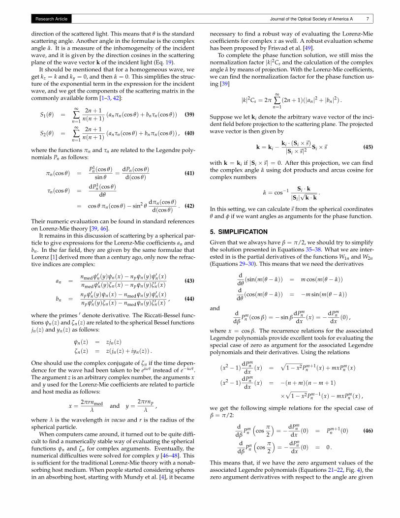
Fig. 4. The zero argument values of the associated Legendrepolynomials Pm
n (0) for n = 0, 1, 2, 3, 4 and m = −4,−3, . . . , 3, 4.
by a right hand shift (or inserting zero if there is no right handneighbour).
The recurrence relations also provide simple formulae forfinding the values of the associated Legendre polynomials them-selves. Using the relations
P00 (x) = 1
Pnn+1(x) = x(2n + 1)Pn
n (x)√1− x2Pm+1
n (x) = (n−m)xPmn (x)− (n + m)Pm
n−1(x)
2mxPmn (x) =
√1− x2
×[(n + m)(m− n− 1)Pm−1
n (x)− Pm+1n (x)
],
we get the following relations for the special case of zero argu-ment:
P00 (0) = 1 (47)
Pnn+1(0) = 0 (48)
Pm+1n (0) = −(n + m)Pm
n−1(0) (49)
Pm−1n (0) = (n + m)−1(m− n− 1)−1Pm+1
n (0) . (50)
These four relations provide a simple forward recurrence forcomputing the zero argument values of all the associated Legen-dre polynomials. Placing the values in a triangle as illustratedin Fig. 4, the algorithm starts with the initial value (47), takesa diagonal step down and to the right to find the last elementof the next row (49), inserts a zero before the last element of therow (48), fills out the remaining elements of the row (50), andgoes back to the last element from where it takes a new diagonalstep (49). This continues until all desired rows have been filled.
The values in Fig. 4 can also be calculated using Equations 21–22. From a numerical standpoint, the recurrence algorithm (47–50) is significantly more attractive as it avoids the factorial func-tion. To make the evaluation of Rm
n equally attractive, we findfrom Equations 21–24 that
Rmn = 21−δm0 (−1)mP−m
n (0) . (51)
These equations also inform us that when n + m is an odd num-ber, the values of Pm
n (0) and Rmn are zero. Thus Rm
n−1Pmn (0) are
zero, and Rmn
dPmn (0)dβ are also zero due to Equation 46. This means
that the functions W2n(θ, π/2) vanish unless we take the partialderivative with respect to β, whence W1n(θ, π/2) would vanishinstead. From this, we conclude that
S3 = S4 = 0 .
Equation 21 also enables us to simplify the expressions forthe scattering components S1 and S2 (35–36). In fact, we can
0.5
30|S1|2 / ( |k|2 Cs)
|S2|2 / ( |k|2 Cs)
0.5
1
30
330
0
|S1|2 / ( |k|2 Cs)
|S2|2 / ( |k|2 Cs)
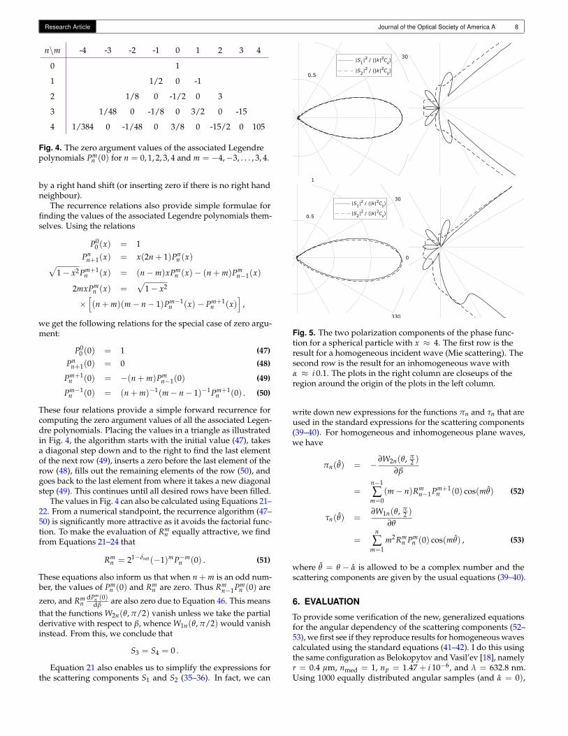
Fig. 5. The two polarization components of the phase func-tion for a spherical particle with x ≈ 4. The first row is theresult for a homogeneous incident wave (Mie scattering). Thesecond row is the result for an inhomogeneous wave withα ≈ i 0.1. The plots in the right column are closeups of theregion around the origin of the plots in the left column.
write down new expressions for the functions πn and τn that areused in the standard expressions for the scattering components(39–40). For homogeneous and inhomogeneous plane waves,we have
πn(θ) = −∂W2n(θ, π
2 )
∂β
=n−1
∑m=0
(m− n)Rmn−1Pm+1
n (0) cos(mθ) (52)
τn(θ) =∂W1n(θ, π
2 )
∂θ
=n
∑m=1
m2Rmn Pm
n (0) cos(mθ) , (53)
where θ = θ − α is allowed to be a complex number and thescattering components are given by the usual equations (39–40).
6. EVALUATION
To provide some verification of the new, generalized equationsfor the angular dependency of the scattering components (52–53), we first see if they reproduce results for homogeneous wavescalculated using the standard equations (41–42). I do this usingthe same configuration as Belokopytov and Vasil’ev [18], namelyr = 0.4 µm, nmed = 1, np = 1.47 + i 10−6, and λ = 632.8 nm.Using 1000 equally distributed angular samples (and α = 0),

Research Article Journal of the Optical Society of America A 9
Fig. 6. Finite-difference time-domain (FDTD) simulation of the scattering by a gold particle in air of a plane wave of unpolarizedlight. Hypothetical wave inhomogeneity is α = 0.5. Three planar slices of the simulated result are compared with the phase func-tion p(θ, φ): (left) φ = 0 and varying θ, (middle) θ = π/2 and varying φ, (right) φ = π/2 and varying θ.
the root-mean-squared difference between (S1, S2) calculatedusing the standard equations (41–42) and the new equations (52–53) was 2 · 10−15, which is only one order of magnitude largerthan the machine epsilon for double precision numbers. Thisis quite convincing given that we are working with expansionsthat require quite a few operations per function evaluation. Theresulting scattering components are in the first row of Fig. 5.
The scattering of a homogeneous wave by a spherical particleis invariant to rotation around the forward direction. In the caseof an inhomogeneous wave with wave vector ki = k′i + ik′′i ,the incident wave is determined by projecting k′i and k′′i to thescattering plane (Eq. 45). If we produce an inhomogeneous waveby means of total internal reflection (an evanescent wave), it willexist along the surface with k′i tangent to the surface and k′′inormal to the surface. In the tangent plane, the projected k′′ isthe zero vector, and the phase function will be the same as forthe homogeneous wave (first row of Fig. 5). In the plane perpen-dicular to the surface, we would have kz real and ky imaginary.The second row of Fig. 5 shows the result for ky = i 1 µm−1,which by insertion in Eq. (19) gives α ≈ i 0.1. The results inFig. 5 (right column) are the same as in Fig. 2a of Belokopytovand Vasil’ev [18]. In the tangent plane, these authors find thatthe result for the inhomogeneous wave differs slightly from theresult for the homogeneous wave. This deviation could be dueto the fact that they are plotting wave intensities rather than thepolarization components of the phase function.
To consolidate the idea of projection to the scattering plane, Icompare with a numerical finite-difference time-domain (FDTD)simulation of a plane wave being scattered by a gold particle inair (nmed = 1). The simulation tool is FDTD Solutions by Lumer-ical Inc. I use two sources to model unpolarized incident light.The wave is configured to have λ = 525 nm and α = 0.5, whilethe gold particle has radius r = 0.05 µm and refractive indexnp = 0.6181 + i 2.144 [50]. The far-field scattered electric vectoroutput from the numerical simulation was normalized so thatit corresponded to a phase function. Results are in Fig. 6. Thecurves match each other well despite a very slight unexpectedshift in the simulation (particularly noticeable in the slice thatvaries the φ angle). This comparison specifically tests the insightthat we can use projection instead of varying the β angle in thesolution. In this hypothetical case where α is real-valued, thesame result is obtained if the projection method is used togetherwith the standard Lorenz-Mie equations (41–42).
n0
nmed
np
z
y
θ0
n
tk0
ki
Fig. 7. Plane wave refracting into an absorbing medium at anoblique angle. The transmitted wave is then inhomogeneous,which influences how it is scattered by a particle.
The transmitted wave due to a homogeneous plane waveincident on an absorbing medium has its wave vector ki in theplane of incidence. Even more specifically, the imaginary partk′′i is in the direction of the inward surface normal [17, 26]. Infact, we can find the wave vector of the transmitted wave usingthe generalized law of refraction [26, 27]:
ki = k0
(~t n0 sin θ0 −~n
√n2
med − n20 sin2 θ0
),
where ~n is the surface normal and~t is the surface tangent inthe plane of incidence. The transmitted wave is most easilydescribed by resolving it into a TE and a TM mode. The forwarddirections for these modes are given by the directions of thecorresponding time-averaged Poynting vectors. These are k′i forthe TE mode and Re(ki/n2
med) for the TM mode [26].We can now construct an example of a plane wave refracting
into an absorbing medium where it becomes inhomogeneousand is scattered by a particle (Fig. 7). Let us consider light ofwavelength λ = 530 nm incident on a methanolic 0.4 mol/lrhodamine 6G solution with nmed = 1.4 + i 0.27 [51]. Supposethis dye solution contains a 400 nm titanium dioxide particle of

Research Article Journal of the Optical Society of America A 10
refractive index np = 2.5 + i 1.4 · 10−7 [52]. We then have a casethat seems relevant in dye based random lasing [29–32]. Thehomogeneous wave in air (n0 = 1) is incident on the surfaceof the dye solution at a 45 angle, thus θ0 = π/4. We choosea coordinate system with the surface normal in the z-directionand the yz-plane as the plane of incidence, such that~t is in they-direction. This is illustrated in Fig. 7, and we now have enoughinformation to calculate ki, which we can insert in Eq. 45.
Let us illustrate the distribution of the scattered light usingtwo special cases: (a) the scattering plane perpendicular to theplane of incidence but containing the forward direction; and (b)the scattering plane parallel to the plane of incidence. In thefirst case (a), the real and imaginary parts of the projected wavevector are both parallel with the forward direction. Thus thescattering components are the same as for a homogeneous waveof light (α = 0). The only difference in this case is in the slightlydifferent forward directions for the TE and TM components.In the second case (b), we have k = ki. In addition, the TEcomponent defines E⊥i and the TM component defines E‖i, sothat the forward directions
S⊥i = k′i and S‖i = Re
(ki
n2med
)
relate to S1 and S2, respectively. These two cases (a and b) areplotted in Fig. 8, where the consequence of the wave inhomo-geneity is seen both in the direction of the forward peak and inthe shape of the smaller lobes. As opposed to the axial symmetryof conventional Lorenz-Mie theory, the scattering distributionhere only exhibits mirror symmetry. The plane of incidence (yz)is the mirror plane in this example. In general, the mirror planeis the plane spanned by the real part and the imaginary part ofthe wave vector.
7. DISCUSSION AND CONCLUSION
I have introduced a practical solution for the scattering of an in-homogeneous plane wave by a particle in an absorbing medium.The solution simplifies to the existing solution for a homoge-neous wave if inhomogeneity (α) is zero. It also simplifies tothe existing solution for an inhomogeneous wave in a nonab-sorbing medium if host medium absorption (n′′med) is zero. Thenew equations for the angular dependency of the scatteringcomponents (Equations 52–53) are easy to evaluate numericallyusing recurrence relations for the associated Legendre polynomi-als with argument zero (Equations 47–51). This solution seemsa practical alternative to the numerical techniques for solvingMaxwell’s equations [36] and the more involved analytical solu-tion [21, 22] that one would otherwise employ.
As is natural in a phase function context, my solution em-ploys a far field approximation. This is done in two places: theassumption of a spherical wave (11) and the approximation ofthe distance-dependent Riccati-Bessel function ζn and its deriva-tive (34). It is however worth noting that the far field assumptionis not required for using the key insight that makes the solutionpractical. The key insight is that we can expand the incidentwave in a way so that we only need to evaluate associated Leg-endre polynomials with argument zero (rather than complexvalued argument). This practical expansion should also be ap-plicable in a vector spherical harmonics context [22], where wewould presumably get computationally attractive formulae forthe electromagnetic field vectors without a far field approxi-mation (but not expressions for the scattering components as
30
330
0
0.5
1|S1|2 / ( |k|2 Cs)
|S2|2 / ( |k|2 Cs)
0.5
1 30
330
0
|S1|2 / ( |k|2 Cs)
|S2|2 / ( |k|2 Cs)
Fig. 8. Polarization components of the phase function for aspherical titanium dioxide particle submerged in a laser dyemedium (as illustrated in Fig. 7). The rows contain the twocases (a and b) described in the main text. With the standardtheory for homogeneous waves (Mie scattering), the result inthe second row (b) would be the same as in the first row withswapped S1 and S2. The plots in the right column are closeupsof the region around the origin of the plots in the left column.
presented here). I leave an investigation of a vector sphericalharmonics solution based on this expansion for future work.
The provided phase function solution seems useful as planewaves are most often inhomogeneous when propagating in anabsorbing medium. A radiative transfer simulation should ac-count for the influence of this inhomogeneity on the directionsof the scattered light. This is particularly relevant because thescattering of light by particles in absorbing media has recentlyfound interesting applications in random lasing and solar cell ab-sorption enhancement. I provided an example to illustrate howscattering is affected by wave inhomogeneity in a configurationsimilar to those seen in dye based random lasing.
REFERENCES
1. L. Lorenz, “Lysbevægelser i og uden for en af plane Lysbølger belystKugle,” Det kongelige danske Videnskabernes Selskabs Skrifter 6, 1–62(1890). 6. Række, naturvidenskabelig og mathematisk Afdeling VI. 1.
2. G. Mie, “Beiträge zur Optik trüber Medien, speziell kolloidaler Metallö-sungen,” Annalen der Physik 25, 377–445 (1908). IV. Folge.
3. M. Kerker, The Scattering of Light and Other Electromagnetic Radiation(Academic Press, New York, 1969).
4. W. C. Mundy, J. A. Roux, and A. M. Smith, “Mie scattering by spheresin an absorbing medium,” Journal of the Optical Society of America 64,1593–1597 (1974).
5. P. Chýlek, “Light scattering by small particles in an absorbing medium,”Journal of the Optical Society of America 67, 561–563 (1977).
Research Article Journal of the Optical Society of America A 11
6. C. F. Bohren and D. P. Gilra, “Extinction by a spherical particle in anabsorbing medium,” Journal of Colloid and Interface Science 72, 215–221 (1979).
7. M. Quinten and J. Rostalski, “Lorenz-Mie theory for spheres immersed inan absorbing host medium,” Particle & Particle Systems Characterization13, 89–96 (1996).
8. A. N. Lebedev, M. Gartz, U. Kreibig, and O. Stenzel, “Optical extinctionby spherical particles in an absorbing medium: Application to compositeabsorbing films,” The European Physical Journal D - Atomic, Molecularand Optical Physics 6, 365–373 (1999).
9. Q. Fu and W. Sun, “Mie theory for light scattering by a spherical particlein an absorbing medium,” Applied Optics 40, 1354–1361 (2001).
10. I. W. Sudiarta and P. Chylek, “Mie-scattering formalism for sphericalparticles embedded in an absorbing medium,” Journal of the OpticalSociety of America A 18, 1275–1278 (2001).
11. P. Yang, B.-C. Gao, W. J. Wiscombe, M. I. Mischenko, S. E. Platnick,H.-L. Huang, B. A. Baum, Y. X. Hu, D. M. Winker, S.-C. Tsay, and S. K.Park, “Inherent and apparent scattering properties of coated or uncoatedspheres embedded in an absorbing host medium,” Applied Optics 41,2740–2758 (2002).
12. G. Videen and W. Sun, “Yet another look at light scattering from parti-cles in absorbing media,” Applied Optics 42, 6724–6727 (2003).
13. Q. Fu and W. Sun, “Apparent optical properties of spherical particles inabsorbing medium,” Journal of Quantitative Spectroscopy and RadiativeTransfer 100, 137–142 (2006).
14. J. Randrianalisoa, D. Baillis, and L. Pilon, “Modeling radiation char-acteristics of semitransparent media containing bubbles or particles,”Journal of the Optical Society of America A 23, 1645–1656 (2006).
15. J. Yin and L. Pilon, “Efficiency factors and radiation characteristics ofspherical scatterers in an absorbing medium,” Journal of the OpticalSociety of America A 23, 2784–2796 (2006).
16. T. C. Fry, “Plane waves of light I. Electromagnetic behavior,” Journal ofthe Optical Society of America 15, 137–161 (1927).
17. T. C. Fry, “Plane waves of light II. Reflection and refraction,” Journal ofthe Optical Society of America 16, 1–25 (1928).
18. G. V. Belokopytov and E. N. Vasil’ev, “Scattering of a plane inhomoge-neous electromagnetic wave by a spherical particle,” Radiophysics andQuantum Electronics 49, 65–73 (2006).
19. D. C. Prieve and J. Y. Walz, “Scattering of an evanescent surfacewave by a microscopic dielectric sphere,” Applied Optics 32, 1629–1641(1993).
20. J.-M. Jin, The Finite Element Method in Electromagnetics (Wiley, 2014),3rd ed.
21. F. Frezza and F. Mangini, “Electromagnetic scattering by a buriedsphere in a lossy medium of an inhomogeneous plane wave at arbitraryincidence: spectral-domain method,” Journal of the Optical Society ofAmerica A 33, 947–953 (2016).
22. F. Frezza and F. Mangini, “Vectorial spherical-harmonics representationof an inhomogeneous elliptically polarized plane wave,” Journal of theOptical Society of America A 32, 1379–1383 (2015).
23. W. H. Press, S. A. Teukolsky, W. T. Vetterling, and B. P. Flannery,Numerical Recipes in C: The Art of Scientific Computing (CambridgeUniversity Press, Cambridge, 1992), 2nd ed.
24. J. A. Doornik, “Numerical evaluation of the Gauss hypergeometricfunction by power summations,” Mathematics of Computation 84, 1813–1833 (2015).
25. T. C. Fry, “Plane waves of light III. Absorption by metals,” Journal of theOptical Society of America 22, 307–332 (1932).
26. E. E. Bell, “Optical constants and their measurement,” in “Light andMatter Ia,” , vol. XXV/2a of Handbuch der Physik (Encyclopedia ofPhysics) S. Flügge and L. Genzel, eds. (Springer-Verlag, Berlin, 1967),chap. 1, pp. 1–58.
27. M. A. Dupertuis, M. Proctor, and B. Acklin, “Generalization of complexSnell-Descartes and Fresnel laws,” Journal of the Optical Society ofAmerica A 11, 1159–1166 (1994).
28. G. Gouesbet and G. Gréhan, Generalized Lorenz-Mie Theories(Springer, 2017), 2nd ed.
29. N. M. Lawandy, R. M. Balachandran, A. S. L. Gomes, and E. Sauvain,
“Laser action in strongly scattering media,” Nature 368, 436–438 (1994).30. X. Wu, W. Fang, A. Yamilov, A. Chabanov, A. Asatryan, L. Botten, and
H. Cao, “Random lasing in weakly scattering systems,” Physical ReviewA 74, 053812–1–053812–11 (2006).
31. J. Yi, G. Feng, L. Yang, K. Yao, C. Yang, Y. Song, and S. Zhou, “Behav-iors of the Rh6G random laser comprising solvents and scatterers withdifferent refractive indices,” Optics Communications 285, 5276–5282(2012).
32. F. Luan, B. Gu, A. S. L. Gomes, K.-T. Yong, S. Wen, and P. N. Prasad,“Lasing in nanocomposite random media,” Nano Today 10, 168–192(2015).
33. J.-Y. Lee and P. Peumans, “The origin of enhanced optical absorptionin solar cells with metal nanoparticles embedded in the active layer,”Optics Express 18, 10078–10087 (2010).
34. J. R. Nagel and M. A. Scarpulla, “Enhanced absorption in optically thinsolar cells by scattering from embedded dielectric nanoparticles,” OpticsExpress 18, A139–A146 (2010).
35. I. Kim, K.-S. Lee, T.-S. Lee, D. S. Jung, W.-S. Lee, W. M. Kim, and K.-S.Lee, “Size dependence of spherical metal nanoparticles on absorptionenhancements of plasmonic organic solar cells,” Synthetic Metals 199,174–178 (2015).
36. S. Yadollahzadeh, S. Alavizadeh, and H. Baghban, “Absorption en-hancement in thin-film photoluminescence layers with metal nanoparti-cles inter-coupling engineering,” Optics and Spectroscopy 118, 930–935(2015).
37. R. K. Harrison and A. Ben-Yakar, “Point-by-point near-field opticalenergy deposition around plasmonic nanospheres in absorbing media,”Journal of the Optical Society of America A 32, 1523–1535 (2015).
38. J. C. Maxwell, A Treatise on Electricity and Magnetism (ClarendonPress, 1873). Two volumes.
39. C. F. Bohren and D. R. Huffman, Absorption and Scattering of Light bySmall Particles (John Wiley & Sons, Inc., 1983).
40. J. H. Poynting, “On the transfer of energy in the electromagnetic field,”Philosophical Transactions of the Royal Society of London 175, 343–361(1884).
41. M. Born and E. Wolf, Principles of Optics: Electromagnetic Theory ofPropagation, Interference and Diffraction of Light (Cambridge UniversityPress, 1999), seventh (expanded) ed.
42. H. C. van de Hulst, Light Scattering by Small Particles (John Wiley &Sons, Inc., New York, 1957).
43. G. Bauer, “Von den Coefficienten der Reihen von Kugelfunctioneneiner Variablen,” Journal für die reinen und angewandte Mathematik 56,101–121 (1826).
44. M. Abramowitz and I. A. Stegun, eds., Handbook of MathematicalFunctions With Formulas, Graphs, and Mathematical Tables, vol. 55 ofApplied Mathematics Series (National Bureau of Standards, Washington,D.C., 1964). Tenth printing, December 1972, with corrections.
45. P. Debye, “Der Lichtdruck auf Kugeln von beliebigem Material,” Annalender Physik 335, 57–136 (1909).
46. J. V. Dave, “Scattering of electromagnetic radiation by a large, absorb-ing sphere,” IBM Journal of Research and Development 13, 302–313(1969).
47. G. W. Kattawar and G. N. Plass, “Electromagnetic scattering fromabsorbing spheres,” Applied Optics 6, 1377–1382 (1967).
48. W. J. Wiscombe, “Improved Mie scattering algorithms,” Applied Optics19, 1505–1509 (1980).
49. J. R. Frisvad, N. J. Christensen, and H. W. Jensen, “Computing thescattering properties of participating media using Lorenz-Mie theory,”ACM Transactions on Graphics 26 (2007). Article 60.
50. P. B. Johnson and R. W. Christy, “Optical constants of the noble metals,”Physical Review B 6, 4370–4379 (1972).
51. Y. Lu and A. Penzkofer, “Absorption behaviour of methanolic rhodamine6G solutions at high concentrations,” Chemical Physics 107, 175–184(1986).
52. T. Siefke, S. Kroker, K. Pfeiffer, O. Puffky, K. Dietrich, D. Franta, I. Ohlí-dal, A. Szeghalmi, E.-B. Kley, and A. Tünnermann, “Materials pushingthe application limits of wire grid polarizers further into the deep ultravio-let spectral range,” Advanced Optical Materials 4, 1780–1786 (2016).