Embed Size (px)
Citation preview

Phantom Operation Manual
1
OPERATION MANUAL
Phantom
SELENE 43
Ocean Trawler
Built by Jet-Tern Marine
Hull No. XJE43027A707
U.S. Documentation No. 1201986

Phantom Operation Manual
2
Welcome aboard!
We are happy you have chosen Phantom for your vacation. We are sure you will enjoy cruising the
lovely islands of the Pacific Northwest.
We had the pleasure of having Jet Tern build Phantom and Townsend Bay Marine outfit her 11 years ago.
We have cruised the Puget Sound, the San Juan Islands, and then Gulf Islands since then, with cruises up
to 60 consecutive days. She was not built to charter, but to actively cruise with a small crew. She is a
dream for two people to handle because of the heavy displacement, bow and stern thrusters, active
stabilizers, and high railings/bulwarks throughout. The custom-made remote steering station takes all the
drama out of docking. The pilothouse design allows us to cruise in any weather, including snowstorms.
We love having an additional couple on board because of the almost equal private guest stateroom. When
the weather is good we live on the flybridge with its built-in settee and table. We have maintained her in
Bristol condition and are often asked “Is that boat new?” She is the perfect size – large enough to be safe
and comfortable, but still small enough to fit in a 50’ slip and hang on Washington State bouys. Life
changes, and while we are not ready to totally stop boating, we have decided to share her with a few other
people who appreciate the finer things in life. If you have half as much fun on her as we have you are in
for a fabulous trip!
We hope this manual will help you become familiar with Phantom. We realize you are experienced boaters
and have tried to limit the manual to the specifics of Phantom. We have some unique ways of doing things.
Please try it our way and see if you like what we suggest. If you have questions about the boat or about
places to visit, please do not hesitate to ask the Fleet Captain for Phantom or the AYC staff.
PRINCIPAL DIMENSIONS
L.O.A.: 47’-7” Fuel Capacity: 640 USG
L.O.H.: 42’-4” Water Capacity: 112 + 225 USG
L.O.D.: 43’-6” Holding Tank Capacity: 60 USG
L.W.L.: 43’-11” Top Speed: 10.5 Kts
Beam: 15’-8” Cruising Speed @ 1650 RPM 7 Kts
Max Draft: 6’-0” Bridge clearance mast up: 23’-3”
Displacement: 60,000 lbs. Bridge clearance mast down: N/A
PHANTOM IS A NO SMOKING VESSEL (Inside). Cigars and single-malt scotch on the top deck on a clear night are recommended. If
you smoke, please do it outside.
PHANTOM IS A DRUG-FREE VESSEL Recreational marijuana is legal in Washington and will soon be legal in B.C. However, it is still
illegal under Federal Law. Phantom is a U.S. Documented Vessel. The U.S. Coast Guard can
board her anywhere in the world. If they find drugs on board they can seize the vessel.
PHANTOM IS A PET-FREE VESSEL Some of our guests have severe pet allergies.
Thank you for respecting these policies.

Phantom Operation Manual
3
Safety First!!
We want you to have a great time on your cruise but most of all we want you to be safe. Please
be careful while cruising on the boat!
The most common cause of injury is slipping on the stairs – inside the boat and outside the boat.
Please use the handrails, especially when going from the pilothouse down to the staterooms.
Also, place your feet SIDEWAYS on the circular staircase leading to the staterooms. (This is
VERY important.) The stairs on the outside walk-around can also get slick when wet. Move
slowly; especially the first few days. Some docks are also unstable. Watch where you are
walking.
During low tide the ramps at Anacortes Marina are very steep. Load the dock cart half way or
less. Always handle the dock carts from the uphill side. Never allow someone between the dock
cart and the dock. If you must let the dock cart go you can replace or dry out the contents. Ask
for help if necessary.
Use caution and the handrails to keep from falling off the boat, especially while underway. The
railings and bulwarks make Phantom a very safe boat. The waters are cold in the Northwest
(45°F) —if you fall in you only have a few minutes before hypothermia sets in. While having
skills for “Man Overboard” are important, not needing them through prevention is even better.
There is a protocol to follow to warm someone. Improperly warming someone can be fatal.
Refer to the following for the proper technique.
https://www.mayoclinic.org/first-aid/first-aid-hypothermia/basics/art-20056624
http://www.princeton.edu/~oa/safety/hypocold.shtml
Fire hazards exist; on board are diesel fuel, propane, and gasoline. All burn, some explode.
Diesel fuel is very safe but keep unintended sparks and flames away!
Do NOT become a human fender! Never get between the boat and anything else: the dock,
another boat or (heaven forbid) a rock.
Use caution around any moving parts—in the engine room, using the winch, using the windlass.
Safety Orientation—know where your safety equipment is located, learn how to use it before you
might need it and discuss and perhaps drill with all on board.
Never kayak alone. Always go with another kayaker or with the dinghy.
Do NOT drink and operate the boat—wait until you are docked or moored for the day.
https://www.boat-ed.com/washington/handbook/page/47/Alcohol-and-Drugs/
Do NOT swim in marinas. Phantom is equipped with an isolation transformer which protects the
boat and swimmers from electrical “leaks.” Other boats and many marinas are not protected, and
it is possible to get an electrical shock that causes your muscles to contract which leads to
drowning. This is a serious issue in fresh water (Lake Washington) but can occur in salt water.
Professional divers report “buzzes” in every marina.
http://www.boatus.com/seaworthy/magazine/2013/july/electric-shock-drowning-explained.asp

Phantom Operation Manual
4
SUPPLEMENTAL INFORMATION .......................................................................................... 8
BOAT OPERATION .................................................................................................................... 8
Electrical Panel ............................................................................................................... 8
Engine Inspection ........................................................................................................... 8
Getting Underway .......................................................................................................... 9
Fuel management ........................................................................................................... 9
Remote Steering Station ............................................................................................... 10
Stabilizers ..................................................................................................................... 10
Start-Up ........................................................................................................................ 10
Shut-Down ................................................................................................................... 12
Cruising ........................................................................................................................ 12
Docking ........................................................................................................................ 12
Dock Lines & Fenders .................................................................................................... 13 Docking Final Approach ................................................................................................................. 14 Seattle Locks .................................................................................................................................. 14
Fueling Up .................................................................................................................... 15
BOAT ELECTRICAL ................................................................................................................ 15
120-Volt AC System ...................................................................................................... 16 Disconnecting from Shore Power .................................................................................................. 16 Connecting to Shore Power ........................................................................................................... 16 Inverter Power ............................................................................................................................... 17 Uninterruptable Power Supply (UPS) ............................................................................................ 18 Battery Chargers ............................................................................................................................ 18 Generator ....................................................................................................................................... 18
House (24-volt) System ................................................................................................. 19 House Battery Bank & Switch ........................................................................................................ 19 Bow/Stern Thruster Breakers ........................................................................................................ 20
12-Volt System ............................................................................................................. 20
SANITATION SYSTEM ........................................................................................................... 20
Marine Toilet ................................................................................................................ 21
Holding Tank ................................................................................................................ 21
Y-Valve ......................................................................................................................... 22
WATER SYSTEM ..................................................................................................................... 23
Fresh Water Tanks ........................................................................................................ 23

Phantom Operation Manual
5
Fresh Water Pressure Pump .......................................................................................... 23
Whole House Water Filter ............................................................................................. 23
Hot Water Tank ............................................................................................................ 24
Shower ......................................................................................................................... 24 Transom Shower ............................................................................................................................ 24
Gray Water ................................................................................................................... 25
Hoses ........................................................................................................................... 25
GALLEY ...................................................................................................................................... 25
Stove ............................................................................................................................ 26
Oven............................................................................................................................. 26
Switching Propane Bottles ............................................................................................ 27
Convection Oven/Microwave ........................................................................................ 27
Refrigerator/Freezer ..................................................................................................... 27
Grunert Freezer ............................................................................................................ 28
HEATING SYSTEM .................................................................................................................. 28
Diesel Heater ................................................................................................................ 28
ELECTRONICS .......................................................................................................................... 30
VHF Radio ..................................................................................................................... 30
Chartplotters ................................................................................................................ 32 Starting the Chartplotters .............................................................................................................. 32 Nobeltec ......................................................................................................................................... 33
Starting Nobeltec ........................................................................................................................................ 33 Stopping Nobeltec ...................................................................................................................................... 35
Chartplotter Tips and Tricks ........................................................................................................... 35 Chart Orientation ....................................................................................................................................... 35 AIS for pleasure craft and sailing vessels .................................................................................................... 36 Vessel course and speed ............................................................................................................................ 36 Tracking Phantom ....................................................................................................................................... 36
Garmin ........................................................................................................................................... 36 Chart Orientation ....................................................................................................................................... 36 AIS for pleasure craft and sailing vessels .................................................................................................... 36 Vessel course and speed ............................................................................................................................ 36 Tracking ...................................................................................................................................................... 36
Radar ............................................................................................................................ 37 Nobeltec ......................................................................................................................................... 37 Garmin ........................................................................................................................................... 38 Radar Tips and Tricks ..................................................................................................................... 38

Phantom Operation Manual
6
Global Positioning System (GPS) ................................................................................... 38
AIS (Automatic Identification System) ........................................................................... 39 Nobeltec ......................................................................................................................................... 41 Garmin ........................................................................................................................................... 42 Getting the Most out of AIS ........................................................................................................... 43
Depth Sounder ............................................................................................................. 44
Autopilot ...................................................................................................................... 44
Maretron ...................................................................................................................... 45
Computers .................................................................................................................... 46
AmbientNav Monitors .................................................................................................. 46
Wi-Fi ............................................................................................................................. 47
ENTERTAINMENT SYSTEMS ............................................................................................... 47
AM/FM Stereo Radio .................................................................................................... 47
TV/VCR ......................................................................................................................... 47
ANCHORING AND BUOYS ..................................................................................................... 48
Anchoring ..................................................................................................................... 48 Setting ............................................................................................................................................ 48 Raising ............................................................................................................................................ 48 Spare Anchor (Should never be needed) ....................................................................................... 49 Anchor Watch ................................................................................................................................ 49 Ultra Trip Hook ............................................................................................................................... 51
Mooring Buoys ............................................................................................................. 51 Picking up buoy .............................................................................................................................. 51 Releasing buoy ............................................................................................................................... 52
CANVAS ..................................................................................................................................... 52 Pilothouse Windows ...................................................................................................................... 52 Flybridge Dash ................................................................................................................................ 52 Flybridge Settee ............................................................................................................................. 52
BARBECUE ................................................................................................................................ 53
DINGHY & OUTBOARD MOTOR ......................................................................................... 53
CRABBING & FISHING ........................................................................................................... 55
OTHER: SAFETY & BILGE PUMPS..................................................................................... 56

Phantom Operation Manual
7
THRU-HULL LOCATIONS ..................................................................................................... 57
APPENDIX A – ELECTRICAL PANEL CONFIGURATION ............................................... 59
APPENDIX B – FUEL MANIFOLD ........................................................................................ 61
APPENDIX C – FUEL BURN AND BOAT SPEED .............................................................. 62
APPENDIX D – HAPPY HOOKER MOORING BUOY GRABBER ................................... 63

Phantom Operation Manual
8
SUPPLEMENTAL INFORMATION
There are electronic manuals for much of the equipment on both computers (NAV and COMM) in the
pilothouse. Look in C:\Phantom\Equipment Manuals\ for various folders. An electronic copy of this
operations manual is located under C:\Phantom\. Other items of interest will also be in this folder. If you
want access to the electronic manual while running the Admiral 10 chartplotter, power up the COMM
computer and switch the starboard screen between digital (Nav) and Analog (Comm). You will also find
this manual and other files on a blue flash drive in the small drawer above the chart table on the starboard
dash. You can copy them to your own computer.
BOAT OPERATION
Over the years we have developed procedures that make boating on Phantom easier. Some of these
procedures are probably unique. We have developed procedures for things a mundane as laying out the
water hose to docking and anchoring using the portable remote steering station. As experienced boaters,
you probably have your own way of doing things and may have suggestions that are better. We would
love to hear them.
Electrical Panel
The electrical panel is in the Pilothouse on the starboard side. There is a small black flashlight velcro’d to
the far starboard bulkhead. Please return it to its rightful place. Set up the 120v panel, the 24v panel, and
the 12v panel before startup. Appendix A shows the recommended configuration when underway,
docked, and moored/anchored. The following paragraphs in this section will briefly discuss boat
operation. More detailed information on each system appears later in this manual. The index is
hyperlinked in the pdf file.
Engine Inspection
Remember your “WOBBS” every morning: Water (Coolant), Oil, Bilges (Inspect and Pump-out), Belts
and Sea Strainer.
All the fluid levels and sea strainers for the engine and generator can be accessed on the port side of the
engine room by entering through the master shower. There should be a flashlight in a small plastic vessel
on your right (port). The transmission fluid level dipstick and SALT WATER WASHDOWN pump (for
anchoring) are located on the starboard side of the engine room and are usually accessed through a hatch in
the salon (unless you are thin and flexible).
Check the level of COOLANT in the expansion tanks located on the starboard side of the engine
room. There is a mark on the tank which shows the normal cold level. You should never have to
add coolant, but if you do have to, use the coolant (Fleet Charge 50/50 mix) stored in the engine
room.
Check the level of OIL in the engine by checking the dipstick located on the port side of the
engine. DO NOT OVERFILL OIL! You should never have to add oil. If you do, please notify
AYC on your return.
Only fill if oil levels are below the ½ way mark. Please use a paper towel, cotton rag or oil rag,
not the dish towels! Extra oil is stored in the engine room port side. Inspect all bilges and pump-

Phantom Operation Manual
9
out if necessary. You should never have to pump the bilges, except possibly the lazarette if there
has been a rainstorm or you washed the boat.
Check the general condition of the BELTS, HOSES, and FUEL LINES. Check the oil asorbent
pads under the engine and transmission. They should show no or very little oil. The engine room
bilge should be dry. There is a clear plastic hose that runs from the refrigerator down to the bilge.
It should go into a Nalgene bottle. If the bottle is more than ¼ full please empty it into the master
head sink or shower sump and put it back in place. Normally, the only water in the bilge is from
the refrigerator defrosting.
Observe the glass of the RAW WATER STRAINER for debris. Shining a flashlight (there
should be one in a bucket just as you enter the engine room) through the strainer often helps see
debris. If necessary, close the seacock, open the strainer cover, clean the strainer, and
reassemble. Remember to reopen the seacock. After start, confirm water flow from the exhaust
(stbd side aft.) Check the generator fluids and sea strainer as well. If you are using he Grunert
freezer check the sea strainer in the starboard locker in the commissary.
Ensure the valve on the RAW WATER THRU-HULL for both the engine and the gen set is in the
‘open’ position (lever in-line with valve).
Check the transmission oil while the engine is in idle using the white dipstick behind the
transmission front housing. You should never have to add oil to the transmission. Look at the
etch marks on each dipstick that indicate the proper oil level. There is a set of ear muff style
hearing protectors at the forward end of the engine room. Please protect your hearing.
The large batteries on Phantom are all Absorbent Glass Mat (AGM) batteries. There is nothing to
check and no way to fill them. Please don’t remove the covers from the battery boxes except in
an emergency.
Getting Underway
This paragraph is a condensed version. More details are in appropriate sections below. REMOVE and
STOW all items on the counters and tables in the Salon. Put the coffee pot in the sink along with anything
else that could damage the floors when it falls. DISCONNECT and stow the shore power cord (see 120-
Volt page 16). DISCONNECT and stow the water hose (details!? Page 25). Unscrew the quick connect
water fitting from the shore water faucet and stow it in cockpit cabinet (lift the lid). Close the PORTHOLES
(no one likes a wet berth), WINDOWS, and FORWARD HATCH. Close the toilet lids and put the white
plastic window coverings on the floor. (Scary bangs happen if you forget.) Turn on your VHF and
electronics (Page 30). SETUP the electrical panel (Appendix A). Start the Navigation systems (Page 32).
SETUP the Remote Steering Station (Page 10). CHECK the operation of the thrusters. ASSIGN crew
members their various positions. Use the bow and stern thrusters to keep the boat near the dock until
everyone is onboard. (1/2 second pulses – 3+ second pause.) Once outside the marina, idle the engines
while the crew brings in fenders and lines. DO NOT DRAG LINES ACROSS THE TEAK CAP RAILS.
See the section on “Dock Lines & Fenders”, page 13 for helpful hints.
Fuel management
There are two 320-gal fuel tanks onboard. This gives you about 150 hours of fuel and a range of 1200
nautical miles at normal cruise speed (1600-1700 rpm). The valves are set in the engine room to draw from
both tanks at all times. The valves on the fuel feed and return manifolds are set the way they should be for

Phantom Operation Manual
10
operation. Appendix B shows how they should be set for normal operation. If you feel there is a need to
change them for any reason, please talk to AYC first. If you are taking the boat for multiple weeks and
want to use the aft water tank talk to AYC about trimming the boat.
Remote Steering Station
If you are going to use the portable remote steering station (highly recommended) when leaving the dock
and docking, set it up before starting the engine. Take the canvas cover off the station and stow it. The
recommended position for the station is on the forward flybridge next to the dock, but it can go anywhere
you see a fish rod holder with a notch in it (8 positions). If you are
shorthanded, you can set it up in front of the pilothouse on the main
deck. Two cables are stored below the settee in the pilothouse. Use the
shorter cable if you are only going to set up the station on the starboard
side. Use the long cable if you may have to set up to port or for
anchoring. Remove the covers from both ends of the cable and store
them on the starboard side of the pilothouse dash. Either end of the
cable can be attached to the steering station. Silver marks will help you
line the cable up. Be gentle. The collar will screw on easily when
everything is lined up. The cable must be screwed into the outlet on the
starboard side of the pilothouse or on the starboard wing on the forward
side of the flybridge. If you are putting the station to port, run the cable
in front of the Portuguese bridge (main deck) or forward of the
instrument cluster (flybridge). Make sure the pin on the stainless post
fits into the notch on the fishing rod holders. The station should be
facing the same direction as the fixed stations in the pilothouse and on
the flybridge. To use, push the throttle select button, both ON buttons
for the thrusters, and the left button on the job lever so the FU light is
lit. After you leave the dock you can leave the station in place and cover it with the canvas cover. Please
keep the station covered when it is not in use.
Stabilizers
Phantom is equipped with Wesmar active stabilizers. They are very effective in reducing roll when
underway over 5 knots. To use, turn on the STABILIZER (#39) breaker on the 24-volt panel. Then turn
ON the Stabilizer switch on the dash. Make sure the stabilizers are in STANDBY until you need them.
You can then push the ENGAGE button to use them. Be sure to push the STANDBY button when
preparing to dock or anchor. That horrible clunking sound you hear at slow speeds is the stabilizers
trying to work with no moving water to divert. The stabilizers work well for roll, but don’t help with
heave. The wake from large powerboats pushing huge volumes of water can result in serious bouncing.
Be sure everything has been stowed before leaving dock. Slow down and try to hit the wake at a 45°
angle. In the summer you will get slammed occasionally. Cursing and hand gestures make me feel
better.
Start-Up
Before starting the engine, do your inspection, install the remote steering station, and totally set up and
check the navigation systems. The engine should be started from the pilothouse. A full set of engine
instruments is located above the Pilothouse helm.
Make sure the FIREBOY breaker (#27) is turned on. If you get no response from pressing the start button
be sure the ENG IGNITION (#12), ELECTRONIC ENG CONTROL (#13), and fireboy switches are on.

Phantom Operation Manual
11
Press the pilothouse “STATION SELECT” button (light to left of button will turn red). Make sure the idle
speed knob is turned all the way to the left (IDLE 1). Make sure the GEARSHIFT is in ‘neutral’ (“N” light
will be lit) or the engines cannot be started because of
the “neutral lockout.” Insert the key into the IGNITION
SWITCH, rotate it about 1/8 turn to the right, and press
the “START’ button to engage the starter. Watch the
oil pressure gauge on the overhead. It should register
about 50 psi when the engine is cold. (Note the mark
on the gauge.) It normally takes about 15-20 seconds
after start for the oil pressure to come up. Check the
wet exhaust on the starboard side of the swim step as
soon as the oil pressure is normal to make sure water is
coming from the wet exhaust. Water will come out in
slugs at idle. This is normal.
If the engine cranks slowly or fails to turn over (which
should never happen), check the condition of the engine
battery on the ELECTRICAL PANEL. If the battery is
low, HOLD the appropriate PathMaker switch (to stbd
and
below helm) UP to combine the house and engine start
batteries. Release the switch as soon as the engine starts.
Alternatively, start the generator and let it charge the
batteries for 15 minutes before trying to start the engine
again. If the engine start battery is low or dead call AYC
and let them know. This should never happen.
After start, either rotate engine idle (red arrow, above) to
IDLE 2 (750 rpm) or IDLE 3 (900 rpm) OR hold the
“Station Select: button (blue arrow) down to disengage the
transmission and while continuing to hold the button down
move the THROTTLE to raise the engine speed to 1000
rpm on the TACHOMETER. Warm the engine for about 2
minutes. MOVE THE IDLE KNOB TO IDLE 1 before
engaging the transmission. Observe the readings of the
gauges. The oil pressure will register about 50 psi when the
engine is cold. The engine temperature should rise slowly.
Note -- If oil pressure is low, shut down engine, and inspect
engine compartment and look for possible cause (for
example, loss of oil.) Caution -- If an engine is overheating or there is lack of raw water expelled in the
engine exhaust, stop the engine immediately. Recheck the raw water-cooling system to ensure the seacock
is ‘open’ (handle in-line with valve). Next, check the raw water strainer for debris. Remove the strainer,
clean, re-assemble, and reopen the raw water intake valve (seacock). Restart the engine and re-check
water flow from the exhaust. If water is not flowing properly, the RAW WATER PUMP may need to be
serviced. Seek help.
TEST both thrusters while tied to dock. Details below.

Phantom Operation Manual
12
Shut-Down
Before shutting down, allow the engine to ‘idle’ for about 5 minutes (600 RPM) to cool it gradually. The
time engaged in docking the boat is usually sufficient. (You will probably approach and dock at 600 rpm.)
Ensure the GEARSHIFT is in the ‘neutral’ position and the IDLE KNOB is in the ‘IDLE 1’ position. Make
sure all docklines are in place and the boat is secure. Turn off engines by pressing the red “Stop” button
either in the pilothouse or on the flybridge.
Cruising
All close quarters maneuvering should always take place at the flybridge helm or using the Remote
Steering Station for maximum visibility.
Make sure the idle control is in IDLE 1 – 600 rpm before engaging the GEARSHIFT. Ideal cruising speed
is about 1600 - 1750 rpm. If you run at 1700 rpm you will cruise at 7.5 knots and use only 4 gallons of
diesel per hour. Your speed will vary depending upon the weight and load and weather conditions.
Note -- Avoid sustained running at less than 1000 rpm or higher than 2000 rpm. Long-term running at
lower engine speeds can lead to “carboning up.” Higher engine speeds cause higher engine and engine
room temperature, possible damage, and dramatically higher fuel consumption with little gain in speed.
(1700 rpm = 4 gph, 7.5 kts; 2675 rpm = 16 gph, 10.2 kts.) In general, lower RPMs result in much-improved
fuel economy. Appendix C has a graph of fuel burn and speed versus rpm. If you need the extra 3 kts to
get out of trouble, then burn the fuel necessary to be safe and then back off. It won’t hurt the engine.
After getting underway, turn ON the E/R BLOWER breaker (#25) on the 24-volt panel. This will help
exhaust hot air from the engine room. You can monitor the engine room temperature on the Maretron in
the pilot house. It can easily get to 102°F. If it gets above that please back off the throttle to 1300 rpm or
so and let it cool down. The blowers are difficult to hear when underway, but sound very loud at dock.
You can turn them OFF as you get ready for docking or leave them ON for as long as you can stand it after
docking to cool the engine room so you're not baking in the master stateroom.
Docking
During docking, use the FLYBRIDGE HELM and the REMOTE STEERING STATION (highly
recommended) for greater visibility. TEST both thrusters. Have your crew make ready the lines and
fenders as described in the next section and give clear instructions on how you will be docking (See the
next section for details). The crew will usually step (not jump!) off from the swim step to handle either the
bow or the stern line. Another crew member may need to be at the bow to hand over the bowlines. If you
set up as described in the next section two people (or even one) can easily handle the boat. Use the thrusters
in short (1/2 sec) bursts, (3+ second wait) to adjust the position of the vessel in the slip or at the dock. Click
the throttle in and out (IDLE 1) to adjust the boat fore and aft. MOVE SLOWLY. Phantom carries a large
amount of momentum. With practice, you can easily make 6-inch adjustments. The goal is no drama.
If someone on dock runs to help you, either you have frightened them, or they are inexperienced. If you
are moving slowly and under control, it might be wise to say “Thanks, but we need the practice.” There
are times when help is very welcome. If the currents or winds are strong, then accept the help. HOWEVER,
you are in command. Have the crew hand them the line you want and then TELL THEM WHAT TO DO.
Never assume they know what they are doing (unless they are paid dockhands like you find at Roche Harbor
who work for tips). The goal in docking is to bore the audience to the point they walk away, mumbling
about cheating and trying to hide their jealousy.
Phantom Operation Manual
13
Dock Lines & Fenders
The dock lines and fender lines are color-coded (!) to make life easier. Normally --- Green goes forward.
Blue goes aft. Red, black, or gold/white goes midships. However, do what you need to do to tie the boat
securely. Usually, a bow line, stern line, and two midships spring lines are all that are necessary.
You can slow down or stop (in a clear area) outside the marina to set up for docking and then proceed
calmly into harbor.
There are 2 green lines – a shorter one and a longer one. The short green line is sized to tie to a cleat
approximately in line with the forward hawse hole. (We call it a “bow” line even though it is technically
a “forward breast line.”) The way we do it is to loop the eye around BOTH horns of the cleat in the
forward hawse hole and cleat it off on the dock. There should be very little extra line left after cleating.
The long green line can be led from the hawse-hole under a bull rail and back over the bull rail to the
hawse hole and tied off on the cleat in the hawse-hole. When leaving, you can throw the line on the dock
and pull it under the bull rail from the foredeck – no excitement. If you are shorthanded when docking,
you can lead the green line aft along the rail, so it can be grabbed from the dock. You can also cheat and
use a boat hook to pull it off the rail. Be very careful not to let it drop overboard and get into the
thruster. That will ruin your day and may ruin your week.
There are 4 blue lines – 2 short ones, 1 medium one, and 1 long one. The short ones tie to cleats
approximately in line with the after hawse holes (“Stern line” or “after breast line.”). Normally, the
hawse holes on the side of the boat are used rather than the ones on the transom. Try to position the boat
so that the stern line does not create a tripping hazard when using the swim step to get on and off the
dock. Anacortes Marina is probably the only place where you will use dock lines on both sides of the
boat. Every other marina will probably be a side tie. When setting up to dock, hold the line in your off
hand (weak hand) and drape the eye outboard of the side of the boat. Reach through the hawse hole and
pull the eye in. For the bow and stern, put the eye over both horns of the cleat in the hawse-hole. DO
NOT DRAG THE LINE ACROSS THE TEAK RAIL. Once the eye is on the cleat, reach through the
hawse hole and pull a loop of line into the boat leaving a short (6” +) tail that can be grabbed from the
dock. The teak rails can easily be “burned” by dragging anything across them and are expensive to repair.
In strong currents or winds, the long blue line may be used to hold the stern close to the dock. Place the
eye over both horns of the cleat in the transom hawse hole furthest from the dock (or put the eye over the
horn closest to the dock) and lead the blue line through the staples (normally, between the top bar and the
middle bar of the one closest to the hawse-hole; or between the swim step and the middle bar) to a cleat
aft of the boat. This crosstie is one of my favorite ways to control the stern, but it is often hard to find the
right cleat setup. You may have to use lines other than the long blue one.
There are 2 red lines, 2 gold lines, and 3 black lines which are normally used as forward and after
Midships Spring lines. Usually, the red lines are the ones to use. Bring them from the line locker to the
midships hawse hole. Run the eye of one of them through the space forward of the stainless railing and
above the gel coat part of the bulwarks. This will keep the line off the teak railing! Pull the eye back
through the hawse hole and hook the eye over one of the horns. The Forward Spring will hook over the
forward horn. (The After Spring will hook over the after horn.) Flake the forward line on the gel coat
toward the forward part of the opening leaving about a foot or so of tail that can be grabbed from the
dock. Do the same with the after line toward the after part of the opening.
The following table contains the length and normal use for the dock lines.

Phantom Operation Manual
14
Line Length Normal Use
Short Green 11.5’ Bow (cleat on dock)
Long Green 21.5’ Bow (bull rail on dock)
Short Blue (2 each) 6’ Aft (cleat on dock)
Medium Blue 12.5’ Aft (bull rail on dock)
Long Blue 21’ Forward after spring (rare) or stern crosstie
Red (2 each) 16’ Midships spring
Gold & White (2 each) 35’ Midships spring
Short Black (2 each) 16’ Midships spring
Long black 20’ Spare
The fenders are usually stored on the foredeck by tying them to the rail with a clove hitch. When
deployed, green is forward; blue is aft – just like the dock lines. Carry the aft fenders either inboard or
over the water either one at a time or two at a time and lay them on the deck. Hold the blue line in your
off hand and lift the fender over the rail making sure you don’t drag it across the teak. Lead the blue line
through the hole in the bulwarks with the cam cleat. Pull the line into the cam cleat with the fender 6” to
12” off the water. (We’ll adjust the height later.) Tie a figure-eight knot in the blue line near the end.
Repeat for the other two after fenders. Usually, you only need one of the forward (green-lined) fenders.
Bring it back near where the stainless rail begins to dive toward the after deck. Look over the side for the
rub rail with the stainless insert. The fender will go about a foot aft of where that ends. Take a wrap
around the top railing and lower the fender to about 12” off the water. Use a clove hitch to secure it
temporarily.
You are now all set up for a no drama docking.
Docking Final Approach
Why colors? Picture this: As you approach the harbor you quietly say. “Please pull a short blue line and
set it up on the starboard side of the stern. Grab the shorter green line and set it up on the starboard side
of the bow. Grab two red lines and set them up on the starboard midships. Remember not to put lines on
the teak rail.” No stress trying to figure out which lines go where.
After entering the harbor lower all the fenders to about 2” off the water. It ruins the desired effect
to have to yell at the crew to lower the fenders as you are about to close with the dock.
After docking, the skipper should check and adjust the lines and trade out the red ones for gold or short
for long or whatever is necessary to feel secure. Even the dockhands at Roche won’t tie them the way
you want.
Seattle Locks
In the line locker, there are two 50’ + lines – one black and one white – with “water bowlines” tied in
them. These are for going through the large locks on the Hiram M. Chittenden Locks leading to or from
Lake Union in Seattle. If you go into the lake, hope for the small lock which only requires normal dock
lines. If you intend to transit the locks, please go over the procedure a couple of times with AYC. The
first couple of dozen times through the locks it’s pretty exciting, especially on a summer weekend with
100 of your closest friends in the big lock. See the videos in C:\Phantom\Ballard Locks\ for a preview.

Phantom Operation Manual
15
Fueling Up
OPEN FILLER CAPS located in small cabinets close to the deck on each side of after part of the cabin with
a DECK FITTING KEY. The key is kept in the key box on top of the cabinet located in the after starboard
salon. (Or use the ends of the pliers on your multi-function tool – Leatherman or Gerber or …)
BRING HOSE ON BOARD THROUGH A TRANSOM HAUSE HOLE OR AFTER DOOR. DO
NOT PULL THE HOSE ACROSS TEAK CAP RAIL OR EVEN
PUT HOSE ON THE CAP RAIL!!!
MAKE SURE YOU HAVE THE RIGHT FUEL! DIESEL! MAKE SURE IT IS GOING INTO
THE RIGHT DECK FILLS! (The water and waste caps are a LONG way from the diesel fill, so this
should not be a problem.)
Before pumping, have some oil/fuel sorbs handy to soak up spilled fuel. The fuel vents are in the small
cabinets where you are fueling. If there is any overfill, it will go into the sump in the cabinets rather than
overboard. Listen for the tank becoming full to know when to stop pumping. You should have a rough
idea of the number of gallons you will need by the engine hour indicator (4 gal/hr * # hrs).
If the fueling station has a high-speed and low-speed pump, use the low-speed one. This will pump about
10 gallons/minute. Place the DIESEL (green hose) nozzle into the tank opening, pump slowly and evenly,
and note the sound of the fuel flow. Pumping too fast may not allow enough time for air to escape, which
may result in spouting from the tank opening (should not be an issue with the low-speed pump). As the
tank fills, the sound will rise in pitch or gurgle. If fuel starts coming into the small cabinet then STOP
PUMPING. You will have to fill both sides; they will equalize too slowly to just fill one side. Top off
carefully and wipe any spillage. Move the fuel hose carefully. They are nasty, greasy things and will mark
the gel coat.
Replace each tank cap. Turn on the blower before starting the engine. Caution -- Clean up splatter and
spillage immediately for environmental and health reasons. Wash hands with soap and water thoroughly.
There are tank gauges on the starboard side below the pilothouse helm which are useful when running, but
not so much when filling the tanks. Button 4 is port fuel. Button 5 is starboard fuel. Make sure 24v switch
labeled “NAUTICAL INSTRUMENTS” (#40) is on. The Maretron system also measures the fuel level,
but it is unreliable during filling. The Maretron should read 320 gallons when the tanks are full.
BOAT ELECTRICAL
The electrical system is divided into THREE distribution systems: 120-volt AC, 24-volt DC, and 12-volt
DC.
The systems are controlled from the ELECTRICAL PANEL located on the starboard forward side of the
pilothouse, and the BATTERY SWITCHES found on the right side of the panel. When not connected to
shore power, batteries are providing all the power. Therefore, monitor the use of battery levels carefully
with your volt meter and amp hours totalizer located next to the Magnum Inverter/Charger in the stairs to
the lower staterooms. The Maretron system also has a battery condition monitor, and one of the screens in
the Master Stateroom has the information.
There are colored dots on each breaker which indicate their “normal” position. Red is normally OFF; Green
is normally ON; Blue is ON for motoring; Yellow is ON for anchoring. When not motoring, the blue dot
Phantom Operation Manual
16
breakers are normally OFF. Some of the breakers have switch covers on them. Do not change the position
of these breakers unless you know why you are doing that.
120-Volt AC System
SHORE POWER supports all AC equipment and receptacles on board, as well as the battery chargers.
Phantom uses 30-amp power which is the most common outlet in the Pacific Northwest. The electrical
cables are stored in the Portuguese Bridge port cabinet. The cabinet also includes an extension cord and
adaptors from 50-amp service to a 30-amp plug which may be necessary in some marinas.
Disconnecting from Shore Power
Power down 120 v electrical loads until the 120v amp
meter reads 0. It will probably be necessary to put
Magnum charger (in stairway to staterooms) on
standby (Red Arrow). (Don’t push the INVERTER
button below the CHARGER button.) The charger
will automatically reset in a few minutes and be ready
to go when you plug into shore power.
REFRIGERATOR (#3) OFF
FREEZER (#21) OFF
WATER HEATER (#4) OFF
Turn OFF 120v forward or aft breaker in the
DC POWER SUPPLY panel (starboard side of
electrical panel). The amp meter should go
blank. Turn off the electrical outlet on shore.
Remove electrical cord from shore and bring
on board. Keep the end out of salt water. If
the end goes in the ocean wash it with fresh
water and dry. Remove the electrical plug
from boat. (Lift SmartPlug locking cover; pull
plug, lock cover over receptacle.) Coil cord,
tie with flex ties and stow in cabinet on port
side of Portuguese Bridge. Check the locking
cover over the receptacle to make sure it is
locked down. (Click)
IF YOU HAD TO USE THE 250V 50A TO 125V 30A ADAPTOR (Roche
Harbor – above right) SAVE YOURSELF $400 AND PUT IT BACK ON
BOARD.
Connecting to Shore Power
To connect to shore power, plug the 30-amp POWER CORD into the boat (make sure to snap the
SmartPlug cover onto the cord to hold it in place “Click”). Then lead the cord over the empty bow roller.
Make sure the power switch on the 30-amp connection on shore is off and plug the cord into the 30-amp
dock receptacle. Check the power rating/plug size of the nearest dock receptacle (that is 50-amp, 30-amp,
20-amp, or 15-amp). If necessary, add a CORD ADAPTER located in the port locker in the Portuguese

Phantom Operation Manual
17
Bridge. Turn the dock power on. Use flex ties or several Velcro ties to attach cord to the railing. Keep
the cord off the deck to avoid collecting dirt.
At the ELECTRICAL PANEL, turn the master shore breaker ON (if necessary), then flip the forward or
aft SHORE CIRCUIT BREAKER on. You may have to slide the slider up or down to select the correct
shore power connection (forward or aft). Check for reverse polarity (Extremely unlikely). In about 15
seconds you will see the load increase as the Magnum Inverter/Charger starts charging the batteries.
Even if you have been motoring for hours, the Magnum will start charging. It should max out at 15 amps
if no one has “adjusted” the settings. Then turn on appropriate breakers for the refrigerator and water
heater. Watch the amp meter for load.
If the load exceeds 30 amps, a breaker will pop. If this occurs, turn off all 120-volt electrical loads. The
forward breaker is in a cabinet above the guest berth on the starboard side. The aft breaker is located in
the lazarette near the forward starboard side of the hatch high on the bulkhead. There is also a breaker
under the pilothouse helm on the forward bulkhead. Open the cabinet doors below the helm and look
deep into the cabinet just to starboard of midline. There is a grey box with a switch. If the switch is
down, it is tripped. If none of these breakers were tripped check the breaker onshore in the power
pedestal. After power is restored watch the amp meter until it gets below 15 amps. Then you can start
turning on loads again.
If your outlets fail to work, make sure they are turned on at the ELECTRICAL PANEL, then check your
GFIs (the button next to the plug in) to make sure that they have not been tripped.
Only use one hair dryer or curling iron at a time and turn off the water heater and freezer while doing so.
Keep the sum of all your loads under 30 amps (unless using the generator as discussed later.)
Inverter Power
The Magnum pure sine wave INVERTER provides AC power to the 120-volt receptacle plugs (i.e., the
microwave oven, computers, and electrical outlets) when the boat is disconnected from shore power. It
switches on automatically when short power is lost. The inverter does not provide power to the water
heater or the battery charger. The inverter control panel is the Magnum panel shown above. It operates
automatically. You should not have to do anything for it to work. The actual inverter is in the
commissary in the port side outboard cabinet.
The inverter’s power source is the DC house or inverter batteries located in the lazarette. The quantity of
DC power is limited to the capacity of these batteries. Therefore, running hair dryers, curling irons,
toaster, coffeepots, microwave, etc. will quickly discharge the house/inverter batteries. If you want to use
a hairdryer or curling iron, turn off the hot water heater and do not use the microwave oven, toaster or
washer/dryer until you are finished. You can use everything; you just need to manage the timing. Use
these items VERY SPARINGLY when using the inverter! Monitor your battery usage very carefully! If
anticipated power usage is heavy, start your generator (preferred) or engines to keep batteries charged.
When connected to shore power, the inverter automatically becomes a battery charger for all the 24-volt
batteries. Should you detect the inverter failing to charge the house batteries, check the circuit breaker in
the AC Panel and the inverter control panel. The inverter breakers - INVERTER INPUT (#17) and
INVERTER OUTPUT (#18) - should always be on. See if someone inadvertently put the charger on
standby. Also, there is usually a circuit breaker located on top of the inverter box in the commissary
(which has never tripped).

Phantom Operation Manual
18
Uninterruptable Power Supply (UPS)
The computers that drive the Nobeltec Admiral navigation system are located under the pilothouse berth
in the large cabinet to starboard of the stairs to the salon. The power for these computers goes through a
UPS (APC Model BR800BLK) located behind the ELECTRICAL PANEL. You should never have to
touch it. If it starts whining or the computer won’t start check it by undoing the barrel bolt at the bottom
left part of the panel and carefully swinging the door open about a foot or two. Stop when you feel
resistance (you can open to about 90°). If the UPS is turned off, turn it on. As you switch from shore
power to inverter, you may hear a short peep out of the UPS.
Battery Chargers
There are three battery chargers on board. The primary charger is the Magnum Charger/Inverter
discussed above. It is set to charge while drawing 15 amps of 120-volt power which should allow you to
simultaneously run the refrigerator and hot water heater while on shore power. The 120-volt breakers
labeled INVERTER INPUT (#17) and INVERTER OUTPUT (#18) should always be ON (24/7).
The 120-volt panel breakers labeled CHARGER HE (#1) and CHARGER SBG (#2) are normally OFF
because they can draw more than 30 amps which will pop one of the shore power breakers.
If you are running the generator and need to load it you can turn ON the 120-volt panel breakers labeled
CHARGER HE (#1) and CHARGER SBG (#2). HE charges the House and Engine battery while SBG
charges the Stern thruster, Bow thruster, and Generator battery.
Generator
Phantom has an 8 kW Northern Lights Model M753W2 genset that can put out 50 amps at 120 v. To
start the GENERATOR, first, check that your generator’s fluids are topped off, and the raw water
intake is open. You can access the generator on the port side of the engine room by going through the
master shower. You will have to open the soundproofing cabinetry surrounding the genset. Be sure to
reinstall the cabinetry.
Prior to starting, make sure all individual AC
(except the computer and inverter) breakers are
turned off. Turn off all the master switches on
the right side of the panel. Hold lever 1 (left
picture) down to activate the glow plugs for about
10 sec. Then pull lever 2 up while holding lever
1 down until the generator starts and oil pressure
has climbed. Let go of lever 1. After the
generator is running, slide the lockout slider on
the right side of the ELECTRICAL PANEL so
you can turn on the generator switch. The
Magnum charger will again start charging at
about 15 amps. Let the gen set warm up to over
100° F and then turn on AC systems as you would
on shore power one system at a time. The genset
should be loaded to about 35 amps which is hard to do. Now is the time to run the freezer, water heater,
dry your hair, dry the bath towels in the washer/dryer, make toast, etc. Do not run the genset for longer
than 30 minutes at or below 15 amps. Turn it off and wait until it can be loaded again. The generator is

Phantom Operation Manual
19
very quiet, so you may want to set a timer on your phone to remember to check it occasionally, especially
if you are underway.
To turn the generator off, first, take off the load by turning off AC breakers (except the computers and
inverter). Then turn off the GENERATOR breaker on the starboard side of the electrical panel (the one
where you had to move the slider to turn on.). Run the genset unloaded for 5 minutes to allow it to
cool down. Set a timer on your phone as you may not hear the genset running. After it has “cooled
down” kill the generator by holding lever 2 down until it dies (about 10 seconds).
House (24-volt) System
Five battery banks support 24-volt DC power: 1) engine battery, 2) generator battery, 3) house battery
bank, 4) bow thruster battery, and 5) stern thruster battery.
There is a round, red BATTERY SELECTION switch on the DC POWER SUPPLY panel (starboard side
of electrical panel.) DO NOT MOVE THIS SWITCH UNLESS THERE IS AN ELECTRICAL FIRE.
The 24-volt panel contains all the systems supported by the batteries except the bilge pumps. Primarily
you will be turning on the breakers for the lights, water pressure, electronics, etc. All but one of the bilge
pumps switches are located on the “mimic” panel high to starboard in the pilot house. One bilge pump
switch (forward crash locker) is located to starboard below the helm. All bilge pumps should be left on
auto.
The breakers for propane should always be turned off after every use. At a minimum, press the button
located above and to the right of the stove to close the remote solenoid-activated valve at the propane tanks.
House Battery Bank & Switch
The HOUSE BATTERY BANK provides power for all DC systems, except the engines, generator,
thrusters, and 5 automatic bilge pumps. When disconnected from shore power, all 24-volt devices drain
the house battery. Use devices only as needed. The DC voltmeter on the DC panel can be switched between
the various battery banks to measure charging or resting battery voltages.
When a battery bank is being charged, the voltage will read from
about 26.2 volts to 28.8 volts depending upon state-of-charge of
the battery bank. When the battery bank is at rest, (that is, not
being charged), the voltmeter can give a rough indication of the
state-of-charge of the battery bank.
All batteries are charged by the engine ALTERNATORS while
underway. All batteries are charged by the BATTERY
CHARGER when connected to shore power. Ensure the
INVERTER INPUT (#17) and INVERTER OUTPUT (#18)
circuit breakers at the electrical panel are ALWAYS ON (except
in case of an electrical fire). The INVERTER OUTPUT switch must be on for any 120v power to be
available. The GENERATOR will also charge the batteries.
There are two battery monitoring systems on board. One is a Xantrex LinkLite monitor located in the
stairway from the pilothouse to the staterooms and the other is the Maretron system (discussed below).
Voltage
(Wet Cell Battery)
Battery State
25.30 volts 100%
24.94 volts 75%
24.50 volts 50%
23.90 volts 25%
23.40 volts 0%

Phantom Operation Manual
20
The Xantrex should normally be on the amp-hour setting where it will
display a bar chart similar to the signal strength chart on your cell
phone.
Bow/Stern Thruster Breakers
The breaker for the thrusters (#36) is located on the 24-volt panel.
Turn it ON before starting the engine.
There is an overload protector for the bow thruster located in the
forward stateroom to port next to the floor. It is the large red knob
that whoever is bunking forward will accidentally kick sometime
during the cruise which will disable the forward thruster. Have
them pull the knob out before starting the engine.
The overload protector for the stern thruster is located in the lazarette
on the starboard side near the cockpit deck. It would be hard to flip it
accidentally, but it could be done.
Once all the breakers are set, the thruster control at the helm must be activated.
Push both ON buttons simultaneously to activate the control. If you change
helm stations, you must push the buttons at that helm station. This is important
when transitioning from the remote steering station to either of the fixed
stations.
If they fail to turn on at the helm station, check the breaker(s). Be aware that
the thruster controls turn off automatically after 7-10 minutes and need to be
re-armed on the helm control.
ALWAYS test both thrusters in both directions before leaving dock and before
entering the harbor. Test them again as you approach the dock. A very short
(1/4 second) pulse will move the boat noticeably, and you can hear them grind
the coffee.
You can let them time out to turn them off or press the OFF button.
12-Volt System
The 12-volt panel is energized by turning on the 12V DC PANEL breaker on the 24-volt panel. Some
items run on 12-volts. The Furuno GPS, Maretron system, Simrad VHF, Flybridge (redundant) VHF
radio, stereo, etc. The Maretron is normally ON 24/7. The others are optional. The flybridge VHF is
lower quality than the main Simrad radio which has a repeater on the flybridge, so it is normally OFF.
NOTE: on the 12v panel there are twice as many breakers as there are loads. Switch on both breakers
next to the sticker, and you won’t have to figure out if the upper or lower breaker is the hot one.
SANITATION SYSTEM
The black water system consists of two Tecma Vaccuflush fresh water heads, a holding tank, a macerator
pump, and an OUTBOARD pumpout fitting.

Phantom Operation Manual
21
Marine Toilet
The material deposited in the heads is stored on board in a tank and pumped
out at an approved pump station at a marina or if we are a long way from a
marina and outside U.S, waters, pumped overboard in deep water. A few
simple rules will make life much easier. The heads are manufactured by
Tecma and use fresh water to flush. They have built-in macerators which
work great as long as the rules are followed. Make sure the Master Head
and Forward Head switches are ON in the 24-Volt panel. The control unit
located near the toilets has two buttons and a green light to indicate it is powered on. The button on the
left fills the bowl and is used before solids are to be deposited. The button on the right empties the bowl
and is used to flush. For liquids only don’t use the left button.
1. Nothing goes in the head unless it has passed through your body or small amounts of marine
toilet paper. i.e., no feminine hygiene products; no condoms; no paper towels; no wet wipes – no
exceptions.
2. Men – please sit to pee. These heads are deviously designed to splash most of the material out of
the bowl if you don’t sit.
3. Close the lid when you finish. If you leave it open, it will drop with a frightening “thump” when
you hit the first small wave.
4. Use the heads onshore whenever possible. That’s why we go to restaurants. And you thought it
was for the food.
5. The head in the guest head is rather small. Sorry about that. Nothing I can do about that now.
It is important that every member of the crew be informed on the proper use of the MARINE TOILET. The
valves, openings, and pumps are small and may clog easily. If the toilet clogs, it is YOUR
RESPONSIBILITY!
Always pump the head for children, so you can make
sure nothing foreign is being flushed.
Caution – Never put paper towels, tampons, Kleenex,
sanitary napkins, household toilet paper, makeup
tissues, or food into the marine toilet. Use only the
special dissolving marine toilet tissue provided by AYC.
The TOILET THRU-HULL is located under the
removable lower shelf in the large cabinet behind the
master head. That is also where the macerator is
located.
Holding Tank
The sanitation HOLDING TANK holds approximately 60 gallons. Be aware of the rate of waste production
(about 1 gallon per flush). With an overfilled tank, it is possible to break a hose, clog a vent, or burst the
tank. The result will be indescribable catastrophe and an EXPENSIVE FIX to you. Empty the tank EVERY
OTHER DAY to avoid this problem. Flushing a few ounces of AYC provided deodorizer will help
eliminate odors. Alternatively, there should be a bottle of Zaal Noflex Digestor next to the master head or
under the master sink. Adding 1 Tsp (+/-) per day to a flush will keep things smelling fine.

Phantom Operation Manual
22
The HOLDING TANK is located under the master stateroom floor near the door. There is a tank watch
warning light located in the master head. It never reads green even when empty. Orange is about 60%. If
it hits red, you must empty the holding tank! The Maretron display in the pilot house has a very accurate
black water level on one of the screens. It will read 0 when the tank is empty. It will show the percent
full unless someone has changed it. If you get to 75%, it’s time to think about how to empty the tank.
The holding tank is emptied in one of two ways:
#1 At the Marine Pump-Out Station, remove
the WASTE CAP located on the outside of
the port bow. BE CAREFUL WITH THE
CAP. The safety chain is not attached, and
it can easily fall into the ocean. Insert the
pump-out nozzle into the waste opening.
Hold nozzle firmly against the fitting to
ensure a tight seal. Turn on pump and
open the valve located on handle. When
pumping is finished, close lever on handle
and turn off pump. Remove the nozzle
from the deck fitting and carefully replace
the cap. (There is also a WASTE fitting
on the port side behind the Portuguese
Bridge. It could be used, but you are
much better off using the one on the port bow.)
If there is a fresh water hose on the dock, rinse the tank by adding 2 minutes of water into tank. Then
re-pump to leave the tank rinsed for the next charterer. This also eliminates head odors.
If you’re having problems getting suction you can open the valve and drop the hose in the ocean. It
will start sucking. Quickly close the valve, jam the nozzle in the opening, and open the valve.
#2 The tank’s contents can be discharged with the MACERATOR only in Canadian waters or beyond the
3-mile limit. Make sure you are out of harbor and in waters where there is a good tidal current.
To operate the macerator, turn on the MACERATOR PUMP (#22) switch on the 24-Volt panel. Cycle
through the Maretron screens until you find the Black Water Tank level. You will hear the diaphragm
pump as it empties the holding tank. It may change sounds when the tank is empty. The Maretron
level will read 0 when the tank is empty. You may want to set a timer on your phone for 5 minutes to
remind you to check the level as the pump is very quiet. It should only take a few minutes to empty
the tank. Turn off the MACERATOR PUMP switch when the tank is empty.
Y-Valve
The Y-VALVE directs waste effluent into the sanitation-holding tank or flushes the effluent “directly
overboard.” The Y-VALVEs are located below the sinks in the heads. A plastic wire tie keeps the handle
pointed to the holding tank – the normal position. Y-valves are usually wire-tied to the holding tank position
in respect to Coast Guard regulations. Please leave it “as is” unless there is an emergency. Be familiar
with the applicable laws concerning dumping sewage directly overboard. If you get inspected by the Coast
Guard, they will check to make sure the Y-valve is tied in the “To Tank” position.

Phantom Operation Manual
23
WATER SYSTEM
Fresh Water Tanks
The FRESHWATER TANKS hold a total of 337 gallons. The forward tank is located on the centerline
under the forward berth and holds 112 gallons which is usually sufficient for four people for two days or
more. The after tank is located to starboard under the master berth and holds 225 gallons. The analog tank
level gauges are to starboard and below the pilothouse helm and show the level of both tanks. (Make sure
the Nautical Instruments switch (#40) is ON.) Press 2 for the forward tank and 3 for the after tank. The
Maretron also has a very accurate level for the forward tank. The Maretron level for the after tank is not
very accurate. If the after tank is filled, the boat will list about 4 inches to starboard. If you are going to
be in marinas often enough to run on the forward tank, don’t use the after tank and avoid the list. If you do
use the after tank, empty it first. AYC will probably fill both tanks unless you ask them not to. You can
always empty the after tank at dock by running water in the Galley sink. It will take a while.
To refill the tank, remove the WATER CAP(S) located just behind the Portuguese Bridge on the starboard
side. Avoid flushing debris from the deck into the tank opening. AYC recommends that you DO NOT fill
water and diesel at the same time.
A MANIFOLD to switch tanks is located on the forward bulkhead in the engine room. Unless you are thin
and flexible, you will have to enter the engine room from a hatch in the salon. The aftermost hatch in the
salon is for the commissary. The next forward hatch is for the engine room. The hatch under the peninsula
is to remove the engine and is not operational. Be sure to turn on the engine room lights by going into the
port side of the engine room through the master shower before opening the hatch in the salon. ONLY RUN
ON ONE TANK AT A TIME. If you open both valves, the pump will suck air as soon as the upper tank is
empty. You can tell when you are about to run out of water by listening to the water pump. It will hiccup
and may not be able to pressure up the system even with the faucets closed. If that happens SHUT DOWN
THE PUMP and change (or fill) tanks.
Fresh Water Pressure Pump
The WATER PRESSURE PUMP is located on the starboard side of the forward bulkhead in the engine
room. Activate the pump at the 24-Volt panel by turning on the breaker (#21). If the water pump continues
to run, either you are out of water or there is an open valve somewhere. If you run out of water SHUT OFF
THE HOT WATER HEATER on the AC panel. Serious damage can occur! If you do run out of water,
you will have to open a faucet after you have filled the tank(s) and turned on the water pressure pump so
that the pump can prime. It is a good idea to turn off the fresh water pump when you are not using it and
especially when you leave the boat for an extended period.
Whole House Water Filter
There is a whole house water filter mounted on the starboard fuel tank near the fireboy. If it becomes
plugged (which should never happen), you can bypass it by changing the three valves near it. This filter
gets the big chunks out but does NOT purify the water. The municipal water in Washington and B.C. is
usually quite good. If you need to change the filter, there is a blue plastic wrench behind the filter
assembly. Replace the rubber gasket at the same time. Close both the inlet and outlet valve and press the
button on top of the filter to relieve the pressure so you can rotate the clear plastic filter holder. If you
leave the rubber gasket out, the filter assembly will spray water all over you and the engine room when
you pressurize the filter assembly. (It’s pretty exciting.)

Phantom Operation Manual
24
Hot Water Tank
The HOT WATER HEATER has a 5-gallon capacity tank and can be heated with 120v power when
connected to shore power (or the genset is running) or via a heat exchanger from the Hurricane Hydronic
heater. To use on shore power, flip ON the water heater circuit breaker (#4) on the AC electrical panel. Do
not use the water heater if the water tank level is very low. The water heater is located in the forward part
of the engine room to starboard.
THE HOT WATER HEATER IS NOT HEATED BY THE ENGINE. To get hot water while at anchor,
moored, or underway you will have to run the Hurricane heater. See the instructions below. There is
enough hot water for 2-3 boat showers if the tank is hot. It takes 15 minutes or so to recover enough to get
the 4th shower. You might stagger your showers morning and night or 2 before breakfast and 2 while
underway. (It’s fun.) However, there is a trick that can result in almost on-demand hot water. The hurricane
heater has a “summer loop” that closes off all the heating loops to the staterooms and salon and diverts all
the hot water from the heater through only the hot water heater. The valves for the summer loop are below
the engine room hatch in the salon along with a picture of how to control the flow. Moving one valve 90
degrees changes back and forth from summer loop to “winter” loop. Put it on “Summer” and shower away.
Change back to “Winter” if you need cabin heat.
There is a “mixing valve” mounted on the hot water tank which lowers the water temperature going into
the hot water pipes and keeps you from getting scalded.
Shower
Before taking a SHOWER, make sure water pressure and shower sump breakers are on. The shower sump
is 120-volt and is wired to the GFCI outlet in the master head. Take only very short “boat” showers (turning
off water between soaping up and rinsing). There is a small valve on the hose next to the shower head.
You can use it to turn off the water without having to use the main shower valve and possibly changing the
temperature of the water. If you use the small valve, it takes a couple of seconds for the temperature to
equalize because the water backflows a short distance. Sometimes it’s a few degrees warmer and sometimes
a few degrees colder. It settles down quickly. The plastic shower curtains keep water from leaking out into
the master head or forward stateroom. In the master head you can turn on the exhaust fan to defog the
mirror. The exhaust fan in the forward shower is wired to the light switch. To keep the shower tidy,
squeezee the shower stall and seat after the last shower. Check for the accumulation of hair in the shower
and sink drains. The sump pump runs intermittently. If there is water above the teak grate, the drain is
probably plugged with hair. The teak grate in the master head is sometimes hard to pull up. There should
be a light line hanging from the shower rod. If necessary, you can insert a loop (“bight”) under one of the
cross members, pull it up with the galley tongs or the pliers on your multi-tool, and run the two “bitter”
ends back through the loop. Now you have a handle to pull the grate up to access the drain. Ensure that
the faucets and nozzle are completely off after using the shower.
Transom Shower
An additional FRESH WATER SHOWER is located on the inside of the transom. Gently pull the
stainless shower head from its resting place. The hose is about 10 feet long and is spooled on a spring-
loaded reel. Pull the hose out to the desired length and then let it spool back for a few inches until it
catches. It operates like an old-fashioned window blind. Depending on the speed of retraction, the reel
either catches or spools up the hose. You will have to play with it to find the right speed, and while trying
to retract it you may have to pull it out a little and let it back in a few times. Like many things, a little
practice makes it easier. After the valves are opened, you will have to push the silver knob on the shower
head down to get water flow. You can either hold the knob down with your thumb which takes quite a bit

Phantom Operation Manual
25
of force or lock it down with the little slide. To unlock the slide, push the knob down which should
release the slide.
Gray Water
Wastewater from the galley sink drains directly overboard through an above-the-waterline thru-hull.
Wastewater from the sinks in the heads and from the showers flows into a plastic box (sump) under the
master stateroom which can be accessed from the hatch at the foot of the bed (berth). Everything put into
the lower sinks and showers is pumped overboard by the pump in this sump.
Hoses
The fresh water hoses are stored in the port locker on the bow next to the anchor windless. There is a
system. The hoses are set up to “click” together using quick connects and have shut off valves. Lift the
top of the cabinet in the cockpit. You will find hose fittings including a Y and an orange fitting to screw
onto the male hose fitting on the dock. There are two hoses in the forward locker. The 25’ green one
ordinarily connects to the orange fitting on dock (or the Y) as it is the larger. If you don’t need extra
length you can start with the blue one (50’). Close the valve on the green hose. Lead the male end of
the green hose over the empty bow roller and plug it into the quick connect. You can now turn on the
dock water without creating a runaway. On board, use a wire tie to attach the green hose to the railing or
the Samson post, then click the male end of the blue hose into the closed valve. Close the valve on the
blue hose and open the valve on the green hose. If you are filling the water tanks wrap the valve end of
the blue hose around the railing next to the fill (starboard) and adjust the length to hold the end of the
hose in the filler. Slowly open the valve and adjust as necessary. The hose should jam in the filler and
you can walk away until you either hear water running on deck or the tank level indicators to starboard of
the pilothouse helm show full.
If you want to rinse the salt water off the boat or rinse the dust off the deck you will find several nozzles
in the cockpit cabinet.
When you disconnect the hose, please be sure to retrieve the piece you screwed on the dock fitting.
There is a salt water hose and nozzle in the starboard bow locker along with all the other paraphernalia for
anchoring. When the anchor is being pulled you can rinse it off with salt water by plugging into the salt
water fitting on the port side of the bow, turning on the DECK WASH PUMP breaker (#24) on the 24-
volt panel, and opening the faucet. After the anchor is aboard you can switch to the fresh water faucet
and get rid of the salt on the deck. Be sure to turn the DECK WASH PUMP breaker (#24) OFF.
Stow the hoses in the appropriate locker.
GALLEY
The galley is fully equipped with a 3-burner propane stove with oven, GE convection/microwave oven,
vertical refrigerator/freezer, dual stainless sinks, and an additional Grunert freezer in the commissary. It
has 8 sets of plates, cups, bowls, glasses, and silverware along with all the kitchen utensils and bowls, etc.
you would need to live aboard for an extended period. There is a “Pampered Chef” covered dish in the
cabinets that will just barely fit in the oven with a little -gentle- effort. It can be used to make a nice one-
pot meal. The two sets of tongs in the front of the silverware drawer are very handy.

Phantom Operation Manual
26
Stove
The stove and oven use propane. The propane stove is activated by the following steps:
1. Turn on one of the three propane tanks located in the locker (the one attached to the hose! 😊)
2. Turn on the 24-volt DC breaker labeled “GAS ALARM (#29).“
3. Press the leftmost “pad” on the solenoid control
panel located to the right of the microwave to
open the solenoid-activated valve in the propane
locker.
4. Turn on the gas at the stove (Press in the burner
control knob and turn counterclockwise) and
light burner. You should hear a “click” as the
piezoelectric lighter snaps. If you don’t hear
clicking, either push in the knob furthest to the
right or use a firestick to light the burner. If this
is the first time you have used the stove, you will
have to hold the knob in for 10-15 seconds while
either “clicking” or keeping a lit firestick near
the burner to purge the air out of the gas line. Continue holding the knob in for a few seconds to
allow the thermocouple to heat up. Then adjust the burner.
The burners are hot. There is a diffuser (movable plate) on the stove that can be used to reduce the tendency
to burn things.
If you create smoke while cooking the smoke alarm on the ceiling in the port after Salon may go off. You
can move it to fresh air by twisting it counterclockwise to remove it. Replace it when done cooking. You
can usually prevent this by using the fan that is part of the microwave.
The gimbals should be in one of the drawers to port of the galley (probably the 3rd one down). If you think
you might want to cook underway, please review their operation with AYC.
Oven
1. It is essential to the proper operation of your oven that the stainless-steel heat disbursement plate
be placed in the lowest shorter racks at the oven bottom with the curved side of the plate down.
(It should be there.)
2. Turn all control knobs to the OFF position.
3. Before lighting the broiler burner make sure that the oven rack has been adjusted to position your
food at the desired height.
4. Push in the oven control knob; this will start the spark ignition system. At the same time turn the
control knob to the desired temperature or to the broil position; hold the knob down until the
burner is lit. Continue holding the burner control knob all the way in for about twenty (20)
seconds after ignition. This will heat the thermocouple and allow the gas valve to stay open. The
thermocouple is designed to cut off the gas supply to the burner if the flame should accidentally
be extinguished.
5. Close the oven door carefully to ensure that the oven burner will not be extinguished.

Phantom Operation Manual
27
6. Remember that broiling is a rapid process. Broil with the Door Open. Check your food often,
and do not run the broiler for more than 20 minutes at a time.
When you are finished cooking, push the button on the solenoid control panel to close the remote valve and
allow the flames to burn out. TURN OFF THE ROUND KNOBS ON THE STOVE. The oven has two
“OFF” settings – one leaves a pilot light burning, and the other turns off all the gas. Unless you are going
to leave the remote valve on and use the oven again soon, make sure the oven is OFF OFF. AYC
recommends you manually turn off the propane at the bottle.
Switching Propane Bottles
It is unlikely that you will have to switch propane bottles, but if it is necessary, there is an adjustable
wrench on a set of fragile hooks on the pilothouse bulkhead in the propane locker which is on the
centerline aft of the Portuguese Bridge against the pilothouse (below the cushion). Tickle the wrench off
the hooks. Remember that flammable gases have a left-hand thread and don’t overtighten. (Notice
the “grooves” on the nut. Let AYC know you had to change propane bottles.
Convection Oven/Microwave
The GE Profile Convection Oven, Microwave is located above the stove. Turn ON the 120-volt
“MICROWAVE OVEN” breaker (#13). You will have to set the clock before you can do anything else.
Press the CLOCK button, turn the large dial to set hours and press the dial. Turn the dial to set minutes
and press. Turn the dial to select AM or PM and press. You will have to do this every time you turn OFF
the switch on the 120-volt panel (hint). The microwave draws almost no electricity when it is not
running.
The microwave works just like you would expect. There is a manual in C:\Phantom\Equipment
Manuals\GE Profile Microwave\
The surface light is very handy when using the stove, and the fan is good to use when frying anything.
If you use the convection oven, please let us know how it works. We haven’t used it in 10 years of
cruising.
Refrigerator/Freezer
The REFRIGERATOR is dual voltage (24-volt and 120-volt power). There are switches on the 120-volt
panel (#3) and the 24-volt panel (#16) to control which voltage it is using. The refrigerator will only operate
on 120 volts when the boat is plugged into shore power or the generator is running. (And the 120-volt
breaker is ON.) Monitor the use of the refrigerator when the engines are not charging the 24-volt battery
system. Minimizing openings helps a lot!
You can monitor the temperature of the refrigerator on one of the screens on the Maretron in the pilothouse.
It will show you the current temperature and the history. The Maretron runs 3-8 degrees hotter than the
thermometers in the refrigerator so it should be about 40°F-43°F to keep lettuce from freezing. The control
knob inside the refrigerator is probably at the proper position when you get on the boat and probably should
not be adjusted. It can take a couple of hours to cool down after you put warm groceries in it. Cranking it
up (down?) will not speed up the process.
The compressor is located in the engine room on the starboard side near the forward bulkhead. There is a
large black flexible hose running from the unit to the lower level. This hose draws cooler air into the
compressor so please leave it in place.

Phantom Operation Manual
28
The freezer above the refrigerator works well.
The refrigerator drains through a clear plastic tube into the engine room bilge. Normally, the hose goes
into a Nalgene bottle to keep the bilge dry. Please empty the bottle if it gets half full by pouring it into the
shower sump or the master head sink.
Grunert Freezer
If you are going to be on an extended trip and want to have several pounds of frozen groceries you can use
the freezer in the commissary. It is controlled by the 120v FREEZER breaker (#21). It takes about 6 hours
to cool from 50°F to 10°F when empty and will hold at about 6°F on
the current setting. One of the Maretron screens in the pilot house
has the current freezer temperature and a graph of historical data.
The freezer only runs off shore power or the generator. When on
shore power, it will cycle about every 4 hours. When cruising, you
can probably get a couple of days out of it before you have to run the
generator to cool it off again if you limit the number of times you
open the box. The compressor is located in the lazarette on the
starboard side. Seawater is circulated to cool the compressor. When
the freezer is running there should be a steady stream of water
coming out of a thru-hull under the swim step on the starboard side.
The seawater strainer is in the starboard locker in the commissary. If
you run the freezer check the water flow and the strainer at least
daily. If you don’t run the freezer, please leave the door cracked so it doesn’t get smelly. You can block
it partially open with a partial roll of paper towels or bubble wrap and bungee the door to keep it from
flopping around in a seaway.
HEATING SYSTEM
The space heating system includes a diesel furnace, plastic tubing running throughout the boat, “air
handlers” which are heat exchangers and fans, and thermostats. Besides heating the living quarters, the
furnace heats hot water when underway or anchored or moored.
Diesel Heater
The DIESEL HYDRONIC FURNACE (“Hurricane Heater”) located in the lazarette provides heat by
circulating a 50/50 mixture of water and non-toxic glycol through PEX tubing. This tubing runs throughout
the boat. All of the closets are heat traced, and you can see the green color of the circulating fluid through
the semi-transparent tubing. There are three thermostats that control the temperature in different rooms –
forward stateroom, master stateroom, and salon. Whenever any one of these thermostats calls for heat the
diesel boiler fires up and begins circulating hot water throughout the entire system. The individual
thermostats control fans on heat exchangers in the rooms. The fans on the individual heat exchangers will
not turn on until the water is up to temperature. If you turn up all three thermostats, you will hear the fans

Phantom Operation Manual
29
come on at different times in the different rooms as the water gets
up to temperature in that particular room. Once a room reaches the
set temperature, the fans in that room will turn off.
The individual “Air Handlers” (heat exchangers with fans) have
individual switches to run the fans at low, high or off. The master
stateroom and master head are on the same thermostat (next to the
master berth), but they have individual fan controllers. The
forward stateroom and forward head are similarly configured. The
salon and pilothouse are on the same thermostat. Pacific Northwest
mornings can be chilly. One trick is to turn the head fan on HIGH,
the stateroom fan on OFF, and increase the thermostat temperature
in the stateroom. This will heat the head faster than the stateroom.
Be sure to lower the temperature again after the head is toasty.
There are two pumps to circulate the hot water – one 120-volt and
one 24-volt. The 24-volt runs automatically, but you should use
the 120-volt one as much as possible. It will run off the inverter as
well as shore power and the generator. The Hurricane will run off
the house batteries at anchor or while on a mooring.
To power up the Hurricane, turn the HURRICANE HEATER
switch on the 120-volt panel to ON. Then turn ON the master
control located on the wall to starboard of the stairs from the salon
to the pilothouse (red arrow). You will see two rocker switches
below the master control. You can safely leave them ON, or you
can follow instructions and only use the heating element on shore
power. If you are hooked to shore power, there is a small electrical
heater that saves some diesel. Adjust the thermostat(s) to the
desired temperature and, if necessary, the Hurricane will
automatically start. It takes about 15 minutes from a cold start to
heat coming out of the air handlers.
Check The furnace EXHAUST PORT located just forward of the
swim step on the starboard side. Do not block this opening when operating the furnace as it will fry anything
that is in front of it. Be particularly careful with dock lines as they will melt and even burn. Once the
Hurricane is on, allow it to run for at least 15 minutes before turning it off. Turn ‘off’ the furnace heater
by lowering the temperature setting on all three thermostats or by switching off the master control (wall by
stairs- red arrow above). The heater will continue to run for a few minutes as it burns all the fuel in its
firebox and goes through an automatic cool down sequence. The best way to turn off the Hurricane if you
are leaving the boat is to switch off the master control.
If you are going to run in heavy seas with waves breaking from the starboard after quarter you can plug the
Hurricane exhaust using the stainless steel adjustable plug stowed in the drawer near the after door under
the settee. THE HURRICANE MUST REMAIN OFF AT ALL TIMES WHEN THE EXHAUST IS
PLUGGED. Put a piece of blue tape over the master control with a note to remove the plug! You should
not be out in those kind of seas. If you want to learn how to do this, ask AYC before leaving.
Because the hot water tubing runs throughout the boat and demand from any thermostat causes all the water
in the system to heat, the master stateroom can get pretty warm if you leave the salon thermostat at a high
(65°F) temperature overnight. Turn the salon down to 55°F or so when you go to bed.
Phantom Operation Manual
30
The people who are often cold will probably prefer the master stateroom while the hot sleepers will probably
enjoy the forward stateroom. The forward stateroom also has a screened hatch that can be opened to cool
it off. Remember to turn your thermostat down so you don’t roast the people in the master.
The tank and fill fitting for the Hurricane antifreeze are under the pilothouse dash. When cold, the level
should be about ¼. When full, the level should be about ½ to maybe ¾. DO NOT OVERFILL. USE THE
SIERRA GREEN (PROPYLENE GLYCOL) 50/50 MIX STORED IN THE COCKPIT CABINET.
Propylene glycol is NOT poisonous and is used in some food, primarily as a thickening agent. The “Fleet”
branded antifreeze used in the engine IS poisonous. Use the correct antifreeze in the appropriate place.
ELECTRONICS
Phantom has an extensive array of redundant electronics. This operations manual will give you some of
the basics, but you will need to refer to paper manuals in the two plastic file carriers in the commissary or
to electronic manuals in the appropriate folder under C:\Phantom\Equipment Manuals\ for more details.
VHF Radio
There are two independent VHF RADIOS (including antennas), one of which has an additional wired
handset on the flybridge. The main radio is a Simrad RS86 mounted to starboard of the pilothouse helm.
It has a large number of features including dual watch (monitor two channels at once), hailer/listening horn,
and automatic fog horn. The paper manual is in the chart drawer to starboard under the pilothouse settee.
The pdf manual is in C:\Phantom\Equipment Manuals\Simrad\RS86 Manual.pdf. To operate turn ON the
VHF breaker in the 12-volt panel. The radio will usually wake up. If necessary, push the ON/C button.
The radio looks for a GPS signal from the Furuno GPS (to port of the helm) and will alert you if it has not
had an updated location recently. There is a wired handset on the flybridge (RS87) to starboard of the helm
that also controls the radio. Whenever you change channels at one of the stations the channel changes on
the other station. They are not independent. Normal hailing is done on Channel 16 which you should
always monitor while underway. After raising your party, pick a working channel (9, 68, 69, 71, 72 &
78A) and switch. If you “converse” on channel 16 the Coast Guard will yell at you. No one seems to use
Channel 9 for hailing in the PNW. Use 22A for a radio check or risk the wrath of the USCG. The Simrad
radio is very powerful. A SQUELCH of 01 is usually the best place to run, but you can increase it if you
are getting interference.
The U.S. and Canadian Coast Guard monitor Channel 16. If you contact the U.S.C.G., they will ask you
to shift to “Channel 22 alpha in the U.S. mode.” Either twist the channel knob or push 2 2. Your radio is
permanently in U.S. mode. The Canadian CG may ask you to switch to 22A or maybe 74. Canada seems
to be using 26 for a radio check.

Phantom Operation Manual
31
Before hailing it’s always a good idea to push the red “16” button to make sure you are on channel 16 as
you may have been listening to the large vessel traffic controllers. If you are using Dual Watch, you MUST
push 16 to hail, even if the radio shows channel 16 on the screen. You can then change to a different
channel.
If your radio emits a two-toned alert for 30 seconds or more that sounds like an ambulance is running over
you, it means someone within 25 miles has pushed the red distress button under the flap at the top right (or
equivalent). Your radio and all other modern radios will retransmit the alert, and the Coast Guard will soon
be on the radio. Be prepared to copy the information. Hopefully, they will broadcast a lat-long rather than
naming some unfindable landmark. If you have a medical emergency or other life-threatening event, lifting
the flap and pushing the distress button will send the boat’s identification and location to the Coast Guard
and all nearby boats. You will get immediate attention. DO NOT TEST THIS.
It is sometimes hard to reach Washington State Ferries on Channel 16. You should not call them unless
you really need to. You may have better luck on Channel 13. Large ships usually ignore radio calls from
small boats, but if you are in a potentially dangerous situation (e.g., engine failure in a shipping lane with
a 20 kt container ship approaching) you can usually get their attention with a “PAN, PAN” call. The coast
guard will pick up on that and help you as well.
You can listen to commercial traffic control on 5A, 11, or 14 depending on your location. There is a list of
what areas are which channel stuck to the autopilot.
When you are close to the other station, push the 1W button. Don’t call marinas on channel 16. They
monitor various other frequencies which are listed in the Waggoner’s Guide. Cell phones are an even better
way to contact them. You can also make slip reservations online at some marinas (Port Sidney).
There is a second, totally independent radio on the flybridge. It is normally OFF because it continually
breaks squelch. If you need to use it, turn ON the FB VHF breaker in the 12-volt panel. It also has a
distress button. If you want to use it to contact a marina from the flybridge while still monitoring channel
16 on the Simrad you can turn it on and off on the face of the radio as necessary.

Phantom Operation Manual
32
Chartplotters
There are two independent navigation systems on board. The primary system runs on a PC located under
the pilothouse settee and uses Admiral 10 to run a chartplotter, radar, and depth sounder (fish finder).
The secondary system is a Garmin with its own charts, and radar. The Admiral 10 system displays on
two AmbiantNav screens in the pilothouse with the port screen being repeated on a Big Bay display on
the flybridge. The Garmin is above and to port of the pilothouse helm and a second station is located on
the flybridge. The systems can be extensively customized, but they are set up to be very functional in the
“default” configuration.
Starting the Chartplotters
Start all the inputs (GPS, etc.) before turning on the computers.
24-volt panel:
RADAR/SOUNDER ---- ON
AUTOPILOT ------------- ON
GPS ------------------------- ON
12V DC PANEL --------- ON
MONITORS -------------- ON
GARMIN ------------------ ON
12-volt panel
GPS ------------------------- ON
VHF ------------------------ ON
CAMERA/AIS ----------- ON
Furuno GPS (Dash) ---------------- ON
Simrad AutoPilot (Dash) --------- ON
120-volt panel:
INVERTER INPUT ----- ON (24/7)
INVERTER OUTPUT -- ON (24/7)
COMPUTERS------------ ON (24/7)
The power switches on the faces of the two AmbientNav monitors should be left on 24/7. (Thus, the blue
tape.)
Power up the NAV computer by pressing the red button to port on the dash in front of the helm. If the
Nobeltec (Admiral) dongle lights up the computer is powering up. If you don’t see anything on the
monitors, turn the brightness knob on the lower right of the monitors to increase the brightness. Both
monitors should come up with a Windows 7 extended desktop. You can use the remote pointer marked N
as a mouse; pull the trigger to click. Push the left arrow to right-click. There is a Kensington wireless
keyboard with integrated mouse pad for each computer. The dongles are plugged into the USB ports on
the dash. There are sliver dots on the keyboards and dongles to pair them. Alternatively, you can plug
the wired trackball into the left set of USB ports. There are various wired and wireless trackballs and
keyboards in the small (but deep) locker on the help station next to the spiral staircase.
You will probably never turn on the COMM computer unless you want to use it for the electronic
manuals while using the NAV computer for navigation.

Phantom Operation Manual
33
Nobeltec
The Nobeltec system drives the open array radar, chartplotter, and fishfinder (depth sounder). The
navigation system is Admiral 10. To use Nobeltec turn on the NAV computer.
There is a Tides & Currents Pro icon on the desktop. This would be a good time to get familiar
with the program. You can also get to it from inside Admiral. You can find tides and currents for many
locations and many dates, past, and future.
Starting Nobeltec Start Admiral by right-clicking on the Admiral icon and “open”ing it. (Or double-click)
Admiral may come up in “PlanView” mode. Since you won’t be using routes, you can go
straight to navigation mode by clicking on the N icon. If you go straight into
navigation mode upon opening Admiral that is even better. The paper
manuals are in the two black plastic folders in the commissary. There is also
a pdf file in C:\Phantom\Equipment Manuals\Nobeltec\
userguide_maxpro.pdf. Additionally, you can reach the same electronic
information by hitting help in Admiral 10.
This manual will cover a few basic areas which will allow you to use Admiral 10 to navigate
safely.

Phantom Operation Manual
34
The standard screens are a large chart to port and radar, depth, and a small chart to starboard. In
the lower right corner of each screen is a control block. Clicking “Menu” turns on and off the vertical
menu on the right. The white diagonal arrows indicate sub-menus. Clicking “Info” in the control block
puts information along the bottom of the screen.
Clicking “Back” and “Next” changes the information displayed. The Target information (shown
above) is the recommended Info. You can change the target displayed (usually the nearest) by clicking on
the white up “arrow” to the left of the word Target.
Clicking “Tool” in the control block replaces the information bar with the toolbar for the active window,
in this case, the chart. You can change the type of chart displayed and make other adjustments.
The normal page on the starboard monitor displays a radar, depth (fishfinder) and a small chart.

Phantom Operation Manual
35
In the picture above, the menu is set on “Tool.” THE FISHFINDER IS SELECTED. (A light-yellow line
surrounds it because it was the last thing I clicked.) The tool bar is specific to the fishfinder.
Stopping Nobeltec You stop Admiral 10 by clicking the EXIT button and selecting QUIT ADMIRAL. Give it some time to
save the files and close gracefully. The Windows 7 screen will come up. You should shut down
Windows from the START button. If you accidentally hit the red button the computer will immediately
power down. It usually powers back up and all is well, but don’t tempt it if at all possible.
Chartplotter Tips and Tricks
Chart Orientation You have a choice of orienting the chart and radar North Up, Course Up, or Heading Up. Some people
prefer North Up which keeps the “world” from spinning every time the boat changes course at the cost of
having to figure out whether to turn right or left, while others prefer Heading Up which causes the chart to
look like the view out the windows. Course Up defaults to Heading Up if no course is specified. Change
the orientation by clicking Menu > Charts > Orientation. You can set the chart differently than the radar.
I prefer chart North Up; radar Course Up, but it all works. You must click on the radar and set its
orientation separately from the chart.
Change

Phantom Operation Manual
36
AIS for pleasure craft and sailing vessels On the Admiral 10 system, vessels that identify themselves as pleasure craft or sailing vessels disappear
from the chart unless Admiral thinks they are a threat. They continue to appear in the information bar at
the bottom of the chart. This reduces the enormous amount of clutter small boats put on the screen.
Vessel course and speed The little green boat shaped icon in the center of the screen is Phantom. The light black coming from the
bow is the heading. The heavy black line is the course. (They may be different because of currents.) The
end of the heavy black line is where you will be in 6 minutes if you continue to hold your course and
speed. This is one of the handier features on the Nobeltec
Tracking Phantom You can turn tracking on and off by clicking Chart > Track and choosing the appropriate button. You
might enjoy tracking your journey and putting it on a flash drive. To put it on the drive, turn tracking on
when you first get on the boat. At the end of the trip, exit Admiral 10 and then bring it up again. When
confronted with the Delete, Export, or Do Nothing prompt, export it to the flash drive.
Garmin
Turn on the Garmin by pressing the power button. The first screen will be the Home Screen. The
Garman has a touch screen for all functions.
You will have to turn on the flybridge Garmin
separately. They are independent units.
You can choose Charts, Radar, or Information.
There is no Sonar or Weather. The manual is
in C:\Phantom\AYC\Equipment Manuals
\Garmin\Garmin_5208_5212_
OwnersManual.pdf
The backlighting is set to Auto and should not
be changed.
If the chart does not look correct, you may
need to pull the SD card and reinsert it.
Chart Orientation You have a choice of orienting the chart and
radar North Up, Course Up, or Heading Up. To change the orientation, touch Charts > Chart Setup or
touch Menu > Chart Setup while viewing the navigation chart.
AIS for pleasure craft and sailing vessels The Garmin has no way to suppress AIS targets. You will notice harbors are painted green from docked
pleasure craft (or painted red if you are close to them.)
Vessel course and speed The little black/red/green boat shaped icon in the center of the screen is Phantom.
Tracking Tracking is normally on for the Garmin and it drops old data off as it puts new data on. There is no way
to export it (that I know of).

Phantom Operation Manual
37
Radar
The following is taken from the Garmin Operating Manual. You probably already know this. The radar
transmitters on Phantom are high off the top deck and should not be an issue. If you are going to climb
onto the top of the pilothouse (not recommended), make sure the radar is OFF. (That’s not a safe place to
be while underway in any circumstances.)
It’s a good idea to run with the radar on even in clear air to get a feel for how it works. It will find targets
that you don’t see with the naked eye. Typically, I run with the Nobeltec at 3 miles and the Garmin at 1
mile. Remember you are not allowed to travel in FOG or in serious wind conditions.
As you get ready to come into dock or a mooring (or , especially, a lock), turn both radars to STANDBY
outside the harbor. Your neighbors will be really grumpy if you are painting them with radar at the dock.
Nobeltec
To run the radar, you must select it (click on
it; watch for yellow lines). Then you can use
the radar tools. In most cases, there are TWO
parts to the Tool menu. You must click Back
or Next (either) to get to the next menu. Once
the radar has been selected and you have
moved to the Next menu, you can start
transmitting by clicking on the appropriate
icon. Hovering over the icons will tell you
what they do.
The “buttons” look like they push in. To set
the radar to standby, click the
Transmit/Standby button. You can use the
tools menu to change the radar range and set
many other options.
The Nobeltec radar does a great job of picking
up small items which is a blessing and a curse.
It will see boats you did not notice, but it will
also pick up waves and, occasionally, birds on
the water as well as clutter next to the boat and
rain. You can adjust the gain, rain, and sea
manually or automatically. Try automatic
until it isn’t doing what you want.
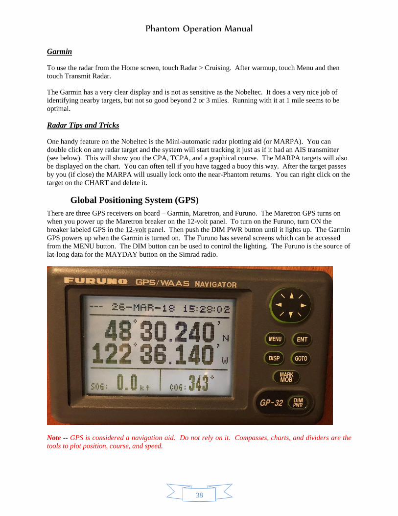
Phantom Operation Manual
38
Garmin
To use the radar from the Home screen, touch Radar > Cruising. After warmup, touch Menu and then
touch Transmit Radar.
The Garmin has a very clear display and is not as sensitive as the Nobeltec. It does a very nice job of
identifying nearby targets, but not so good beyond 2 or 3 miles. Running with it at 1 mile seems to be
optimal.
Radar Tips and Tricks
One handy feature on the Nobeltec is the Mini-automatic radar plotting aid (or MARPA). You can
double click on any radar target and the system will start tracking it just as if it had an AIS transmitter
(see below). This will show you the CPA, TCPA, and a graphical course. The MARPA targets will also
be displayed on the chart. You can often tell if you have tagged a buoy this way. After the target passes
by you (if close) the MARPA will usually lock onto the near-Phantom returns. You can right click on the
target on the CHART and delete it.
Global Positioning System (GPS)
There are three GPS receivers on board – Garmin, Maretron, and Furuno. The Maretron GPS turns on
when you power up the Maretron breaker on the 12-volt panel. To turn on the Furuno, turn ON the
breaker labeled GPS in the 12-volt panel. Then push the DIM PWR button until it lights up. The Garmin
GPS powers up when the Garmin is turned on. The Furuno has several screens which can be accessed
from the MENU button. The DIM button can be used to control the lighting. The Furuno is the source of
lat-long data for the MAYDAY button on the Simrad radio.
Note -- GPS is considered a navigation aid. Do not rely on it. Compasses, charts, and dividers are the
tools to plot position, course, and speed.

Phantom Operation Manual
39
AIS (Automatic Identification System)
The AIS is controlled by a breaker on the 12-volt panel labeled “CAMERA” with AIS on white tape
below it. It should always be ON while motoring. The AIS targets will automatically appear on the
chartplotters and radars.
All large vessels (> 150 tons) are required to have an AIS which broadcasts their position, speed, and
other information. AIS is one of the best things to ever be required on large vessels. It increases safety
and reduces anxiety. Pleasure craft may have an AIS transmitter. Phantom has an AIS receiver, but not a
transmitter. AIS targets show up on your chartplotter and radar as icons with a line extending from them.
That line shows where they will be in 6 minutes if they maintain their course and speed. It your 6-minute
line and their 6-minute line cross at 6 minutes (or 5 or 4 or 3!!!!) then you may have to act IF THEY ARE
A LARGE CRAFT. If they are a 30-foot sailboat under power, the normal rules of the road apply, and
you MAY be the stand-on vessel. The AIS is constantly computing the Closest Point of Approach (CPA)
and the Time to Closest Point of Approach (TCPA). On the Nobeltec you can see this information and
more in the information ribbon across the bottom the chart (or radar) IF you have scrolled through the
information bars to get to it. IT IS HIGHLY RECOMMENDED THAT YOU RUN WITH THIS INFO
BAR ACTIVATED. If the AIS thinks there is a threat of collision (within 0.5 nm), it will turn the icon
and line for the other boat RED. Don’t panic. Ferries and large container ships follow specific lanes that
are shown on the chart. If they are going to turn away in a minute, then you may be fine. The ferries do a
nice job of trying to avoid you without telling you. Just stay away from the ferry paths on the chart (if
you can do so safely).
One of the nicest things about AIS is that it is not line-of-sight like radar. It allows you to see “behind”
islands. For instance, if you are headed to San Juan Island, you can watch the ferries headed to Thatcher
Pass (between Blakely Is and Decatur Is) while they are still behind Blakely.
You can estimate when they are going to pop out from behind Blakely at 17 kts and take appropriate
action which may mean going north of Lawson Rock before crossing the Ferry Route as you round the
southernmost point on Blakley. The passage between Willow and Blakely is quite wide and usually a
nice place to transit. Watch your AIS, however, because sometimes ferries use that passage and while it
is not difficult to fit Phantom and a ferry in the passage it does generate some anxiety.

Phantom Operation Manual
40
The difference between the Nobeltec and Garmin is shown below:

Phantom Operation Manual
41
Nobeltec
Notice the Green icon in Anacortes Marina which is Phantom. Our heading is slightly east of south. The
Sioux Arrow is going to hit us in 4 minutes unless she changes course or speed. (She is going to do both
as she is going into
Cap Sante Marina.)
The boats north of
Anacortes are large
tugs or other
commercial craft.
Notice that Anacortes
Marina is totally RED.
Those are all docked
pleasure craft with
their AIS transmitters
running. They show
up in red because the
computer thinks they
are threats (their
course will “pass”
within 0.5 nm of your
course). The black X
is an AIS on a boat
stored onshore that has
not transmitted
recently. Notice Cap
Sante Marina shows
only two boats.
(which are commercial
boats). We will
contrast that to the
Garmin soon. (The
wavy interference
pattern is because this
is a photograph of a
computer screen – you
will not see it.)

Phantom Operation Manual
42
Garmin
The Garmin does not show the
Sioux Arrow because the picture
was taken after she had entered
Cap Sante Marina. There is a
black and green and red icon
representing Phantom hidden in
the middle of the sea of RED
pleasure craft that the Garmin
thinks are dangerous targets.
Notice that Cap Sante Marina is
covered in GREEN. Those are
transmitting pleasure craft that
the Garmin does not suppress and
that it does not deem are threats.

Phantom Operation Manual
43
Getting the Most out of AIS
Run with the AIS info bar activated at the bottom of either on the port or starboard AmbientNav computer
screens. The info bar will normally show the nearest AIS target which may not be of interest. You can
switch to a boat of interest by double-
clicking on the boat icon or by
clicking on the white “arrow” or
triangle just to the left of the word
“Target:”. This will bring up a list of
the 30 closest targets sorted by
distance from Phantom. When you
click on the desired target, it will
show up in the info bar along with its
CPA, TCPA, RNG, etc. It will also
show size of the vessel and its MMSI
number in a little box on the right
side of the info bar. You can often
tell the kind of craft by the name.
After you are done watching a
particular target, be sure to CLICK
ON CLOSEST so you are back to
normal running.
Watch the 6-minute lines. If they are
long, the target is moving fast. The
Victoria Clipper and San Juan
Clipper run about 27 knots. You can
tell who they are by the length of the
line. The line also shows
if they are making a turn.
A small flag indicates a
slow turn; a curved line
indicates a fast turn. Each dash and
space is 1 minute. Both
these targets are turning to
starboard, but at different
rates of turn.
AIS is also very useful for whale
watching. You will see fast boats
flying out of Victoria (Prince of
Wales) and Vancouver and Anacortes
(Mystic Sea and Island Adventures).
You can often tell by their speed and
name that they are whale watching
boats. If you see them suddenly stop
or slow down and cluster together “thar be whales.”
When a ferry is docked near your path, you can set them as the target to watch and keep track of their
speed. If you see their heading line look “outbound” and the speed goes to 0.3 kts and climbing you
know they are underway and you can make sure you are out of the ferry lane.

Phantom Operation Manual
44
Depth Sounder
There are two DEPTH SOUNDERS, one is a fishfinder which displays a depth profile and water
temperature profile on the Nobeltec system, and the other is a single point sounder which displays on the
Maretron and on the Garmin. To activate the Nobeltec DEPTH SOUNDER, turn ON the breaker on the
24-volt panel labeled “SOUNDER.”. The Maretron sounder comes on automatically when the Maretron
breaker is ON. The Nobeltec display automatically changes range as the depth changes. Occasionally, it
locks onto clutter and shows a very shallow depth. You can click on the display to “activate” it, switch to
the “Tool” bar, and manually adjust the range until it finds the true bottom. Then switch back to auto depth.
You can also play with the frequency (50 Mhz for deep, 200 MHz for shallow), clutter, gain, etc. Most of
the time setting everything to AUTO works well. The Nobeltec sounder can easily find the bottom in 1000
feet of water at 50 MHz.
The Maretron sounder will only work to about 200 feet. If you are in deeper water than that, the Garmin
depth (lower left of screen) will read something like 5.9 feet and blink. Warn your guests about this since
it can create anxiety.
Both sounders are set to read depth below the waterline. Therefore, if they read 6 feet you are aground!
Try to anchor or moor so that you will have 4 feet under the keel at low tide (10 feet on the depth sounder.)
The sounders may show depths that are a foot or two different in shallow water and several feet different
in deeper water. Be conservative.
Remember, ALWAYS consult your charts for depth! When you are in bays with shallow slopes and harbors
the depth sounder is quite useful. Around reefs and rocks do not think you are safe if you are in 30 feet of
water (or more). The reefs and rocks are quite steep, and you can show 30 feet in the middle of the boat
while the bow is on a rock.
Autopilot
Phantom is equipped with a full-featured Simrad (Robertson) AP25 autopilot. Turn on the AUTO PILOT
breaker (#34) on the 24-volt panel. Then push the STBY PWR button to turn it on.
You will not be using routes unless that has been approved by your fleet captain so the NAV button will
not be discussed. However, you can use the AUTO function which will hold the heading that you dial
into the autopilot. Even if you are steering by hand, the autopilot must be ON as it provides heading
information to the chartplotter. The
autopilot has several screens, but the one
shown here is the most useful. The large
numbers show the status of the autopilot
and the heading. “S” means the autopilot
is in standby mode and steering is done
from the wheels. “A” means the
autopilot is in AUTO mode and “George”
will hold your heading. “N” is nav mode
where the autopilot is following a route
from the chartplotter. You should never
see this mode.
If you are in AUTO mode, the wheel will NOT change the rudder angle. You can spin the wheel all you
want, and the boat will not turn. To use the wheel, you must push the STBY button. It is a really good
idea to push the STBY button whenever you get ready to make turns with the wheel to lock in the muscle

Phantom Operation Manual
45
memory. That way if you are ever in AUTO mode and have to make a quick turn you will push STBY
without having to think about it.
Talk to your fleet captain about running in AUTO. Done properly, running in AUTO is a good way to
reduce fatigue and stress. When in AUTO mode you can change the heading by rotating the knob. One
click is one degree. Pushing the arrows below the knob will change the heading 10 degrees. Unless you
are an AP25 wizard, it is best to push STBY and hand steer rather than using the DODGE function.
There are numerous other functions on the AP25 that have little use while cruising.
The rudder angle is shown below the heading. The rudder sensor is very sensitive.
Maretron
Phantom is equipped with a Maretron NEMA 2000 system that allows for monitoring tank levels, battery
condition, engine information, temperatures, and many other things. There are three multifunction
displays – pilothouse, flybridge, and master stateroom. Each of these displays has 16 screens displaying
information. The pilothouse and flybridge displays primarily have navigation and engine information,
although the pilothouse display also has refrigerator and freezer temperatures, and tank levels for fresh
water and black water. The detailed
instructions for the displays are
contained in
C:\Phantom\Equipment Manuals\
Maretron\DSM250UM_1.6.2.pdf.
Various alerts can also be set. There
is only two alerts currently set on
Phantom – the anchor watch, which
is more fully explained under the
section on anchoring and an overheat
on the exhaust which would indicate
a saltwater pump failure on the main
engine.
The Maretron system is normally
always ON (24/7). Turn on the
MARETRON breaker on the 12-volt
panel (#0). Press and release the
leftmost button on the display to
power it on locally. You will have to
power on all three displays
separately. Press the rightmost
button (enter) to accept the
disclaimer. Use the arrow keys to scroll through the screens. When you reach the engine screens, you
will have to accept another disclaimer. Some of the engine information will not be available until the
engine ignition is ON.
The display in the master stateroom has battery charge information and various temperatures. Scroll
through the screens to see what is available.
The second button from the left (the light) controls both dimming (short push) and the screen color (long
push). Black lettering on a white background is usually the most readable in daylight. Red is usually the
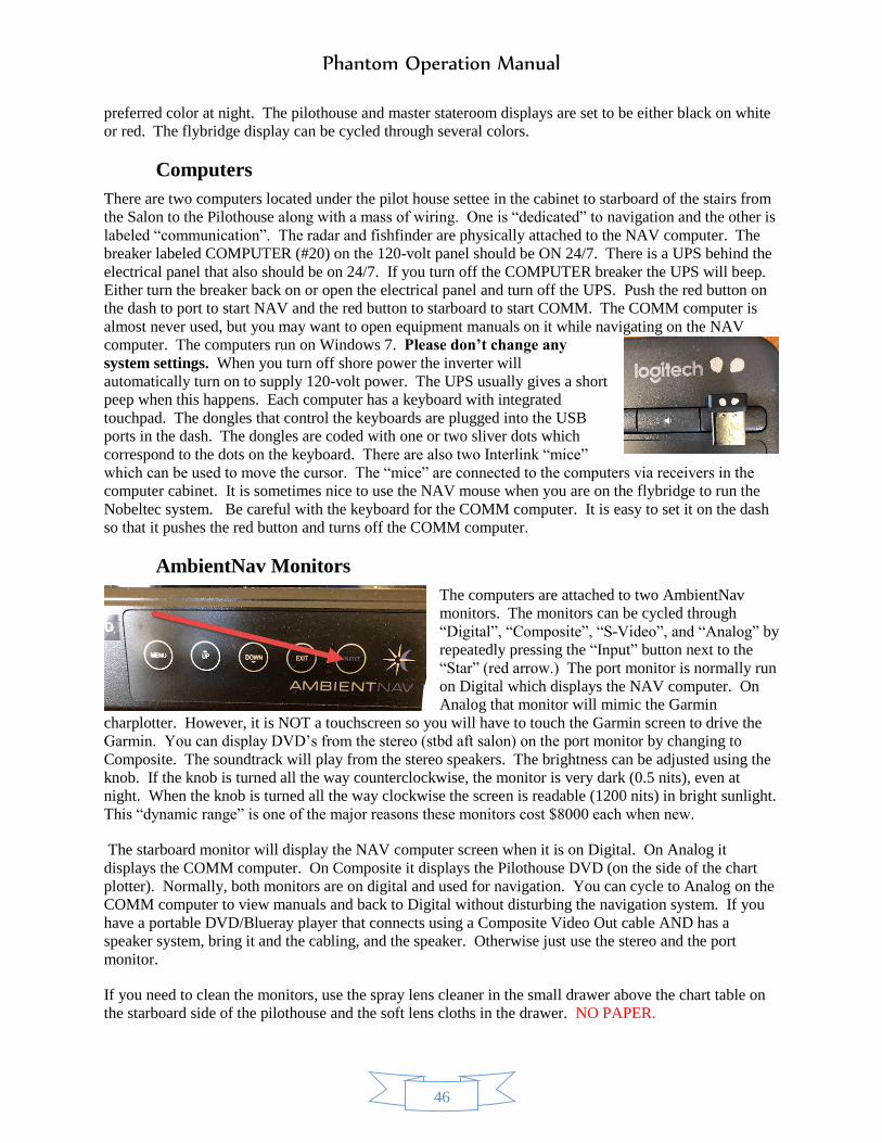
Phantom Operation Manual
46
preferred color at night. The pilothouse and master stateroom displays are set to be either black on white
or red. The flybridge display can be cycled through several colors.
Computers
There are two computers located under the pilot house settee in the cabinet to starboard of the stairs from
the Salon to the Pilothouse along with a mass of wiring. One is “dedicated” to navigation and the other is
labeled “communication”. The radar and fishfinder are physically attached to the NAV computer. The
breaker labeled COMPUTER (#20) on the 120-volt panel should be ON 24/7. There is a UPS behind the
electrical panel that also should be on 24/7. If you turn off the COMPUTER breaker the UPS will beep.
Either turn the breaker back on or open the electrical panel and turn off the UPS. Push the red button on
the dash to port to start NAV and the red button to starboard to start COMM. The COMM computer is
almost never used, but you may want to open equipment manuals on it while navigating on the NAV
computer. The computers run on Windows 7. Please don’t change any
system settings. When you turn off shore power the inverter will
automatically turn on to supply 120-volt power. The UPS usually gives a short
peep when this happens. Each computer has a keyboard with integrated
touchpad. The dongles that control the keyboards are plugged into the USB
ports in the dash. The dongles are coded with one or two sliver dots which
correspond to the dots on the keyboard. There are also two Interlink “mice”
which can be used to move the cursor. The “mice” are connected to the computers via receivers in the
computer cabinet. It is sometimes nice to use the NAV mouse when you are on the flybridge to run the
Nobeltec system. Be careful with the keyboard for the COMM computer. It is easy to set it on the dash
so that it pushes the red button and turns off the COMM computer.
AmbientNav Monitors
The computers are attached to two AmbientNav
monitors. The monitors can be cycled through
“Digital”, “Composite”, “S-Video”, and “Analog” by
repeatedly pressing the “Input” button next to the
“Star” (red arrow.) The port monitor is normally run
on Digital which displays the NAV computer. On
Analog that monitor will mimic the Garmin
charplotter. However, it is NOT a touchscreen so you will have to touch the Garmin screen to drive the
Garmin. You can display DVD’s from the stereo (stbd aft salon) on the port monitor by changing to
Composite. The soundtrack will play from the stereo speakers. The brightness can be adjusted using the
knob. If the knob is turned all the way counterclockwise, the monitor is very dark (0.5 nits), even at
night. When the knob is turned all the way clockwise the screen is readable (1200 nits) in bright sunlight.
This “dynamic range” is one of the major reasons these monitors cost $8000 each when new.
The starboard monitor will display the NAV computer screen when it is on Digital. On Analog it
displays the COMM computer. On Composite it displays the Pilothouse DVD (on the side of the chart
plotter). Normally, both monitors are on digital and used for navigation. You can cycle to Analog on the
COMM computer to view manuals and back to Digital without disturbing the navigation system. If you
have a portable DVD/Blueray player that connects using a Composite Video Out cable AND has a
speaker system, bring it and the cabling, and the speaker. Otherwise just use the stereo and the port
monitor.
If you need to clean the monitors, use the spray lens cleaner in the small drawer above the chart table on
the starboard side of the pilothouse and the soft lens cloths in the drawer. NO PAPER.

Phantom Operation Manual
47
Wi-Fi
Phantom is equipped with a Wi-Fi router and an antenna on the mast that increases wi-fi range. You
probably will connect all your devices to the Wi-Fi router and then connect the router to the internet
connection in port. The router is named “Phantom”. The password is posted on the pilothouse dash or
available from your fleet captain. After connecting to the router, connect to the internet by entering the
URL http://192.168.89.1/ (If you open Internet Explorer or Chrome you will find a shortcut to this
URL.) You will now see a list of possible wireless internet connections. Click on the appropriate one
and, if necessary, enter the login credentials provided by the marina. Now, everyone can access the
internet. There are some places in the islands where you can access the internet using a phone hotspot.
One example is the southeastern buoys in Echo Bay on Sucia Island, especially with Verizon. The cell
coverage is quite good in the San Juans and Gulf Islands. There are probably many other places where
you can get internet over phone.
If you don’t have a Canada Roaming plan be very careful as you get north of Orcas Island and into the
Matia/Sucia/Patos area. You may get attached to Rogers or Shaw which are Canadian carriers. Check
with your carrier about roaming charges. (Internet in Canadian marinas is usually free, and you may be
able to use internet calling.)
ENTERTAINMENT SYSTEMS
AM/FM Stereo Radio
The JVC Model KD-DV5300 unit is located in the cabinet in the salon next to the after door. It operates
like a normal car radio. Detailed instructions are in C:\Phantom\Equipment Manuals\JVC\GET0444-
001A.pdf. There are two speakers (stereo) in the salon, two in the pilothouse, two in the master stateroom,
two in the forward stateroom, and two (stereo) on the bridge. The FADER controls the distribution of the
salon and bridge speakers. F is the Flybridge; R is below decks. If you are using the stereo only below
decks, do your neighbors a favor and FADE to R 06. That will shut down the Flybridge speakers. The
BALANCE controls the sound distribution in the left and right speakers. There is a remote control (line of
sight) velcro’d to the after side of the cabinet. The master volume can be controlled from this remote.
There are knobs that control the volume to the below decks speaker in each room. In the salon the black
knob is to starboard of the stove. In the pilot house the white knob is on the interior wall of the chart table
(stbd side of dash). The black master stateroom knob is next to the Maretron panel forward of the master
berth. The black guest stateroom knob is to starboard near the thermostat and air-handler fan control.
DVD/CD Changer
At the top of the radio there is a slot for CD’s and DVD’s. You can watch DVD’s on the port monitor in
the pilothouse using the radio. Put the port monitor on composite, insert the DVD in the slot in the radio,
and enjoy. You can bring your audio CD’s and DVD’s from home. Remember to take them at the end of
the trip.
TV/VCR
This vessel does not have a TV. There are many places in the islands where you can stream TV stations on
a personal device over the internet.
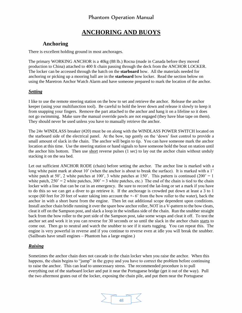
Phantom Operation Manual
48
ANCHORING AND BUOYS
Anchoring
There is excellent holding ground in most anchorages.
The primary WORKING ANCHOR is a 40kg (88 lb.) Rocna (made in Canada before they moved
production to China) attached to 400 ft chain passing through the deck from the ANCHOR LOCKER.
The locker can be accessed through the hatch on the starboard bow. All the materials needed for
anchoring or picking up a mooring ball are in the starboard bow locker. Read the section below on
using the Maretron Anchor Watch Alarm and have someone prepared to mark the location of the anchor.
Setting
I like to use the remote steering station on the bow to set and retrieve the anchor. Release the anchor
keeper (using your multifunction tool). Be careful to hold the lever down and release it slowly to keep it
from snapping your fingers. Remove the part attached to the anchor and hang it on a lifeline so it does
not go swimming. Make sure the manual override pawls are not engaged (they have blue tape on them).
They should never be used unless you have to manually retrieve the anchor.
The 24v WINDLASS breaker (#20) must be on along with the WINDLASS POWER SWITCH located on
the starboard side of the electrical panel. At the bow, tap gently on the ‘down’ foot control to provide a
small amount of slack in the chain. The anchor will begin to tip. You can have someone mark the anchor
location at this time. Use the steering station or hand signals to have someone hold the boat on station until
the anchor hits bottom. Then use short reverse pulses (1 sec) to lay out the anchor chain without unduly
stacking it on the sea bed.
Let out sufficient ANCHOR RODE (chain) before setting the anchor. The anchor line is marked with a
long white paint mark at about 10’ (when the anchor is about to break the surface). It is marked with a 1’
white patch at 50’, 2 white patches at 100’, 3 white patches at 150’. This pattern is continued (200’ = 1
white patch, 250’ = 2 white patches, 300’ = 3 white patches, etc.) The end of the chain is tied to the chain
locker with a line that can be cut in an emergency. Be sure to record the lat-long or set a mark if you have
to do this so we can get a diver to go retrieve it. If the anchorage is crowded put down at least a 3 to 1
scope (60 feet for 20 feet of water taking into account the +- 6’ from the bow roller to the water), back the
anchor in with a short burst from the engine. Then let out additional scope dependent upon conditions.
Install anchor chain bridle running it over the spare bow anchor roller, NOT in a V-pattern to the bow cleats,
cleat it off on the Sampson post, and slack a loop in the windlass side of the chain. Run the snubber straight
back from the bow roller to the port side of the Sampson post, take some wraps and cleat it off. To test the
anchor set and work it in you can reverse for 30 seconds or so until the slack in the anchor chain starts to
come out. Then go to neutral and watch the snubber to see if it starts tugging. You can repeat this. The
engine is very powerful in reverse and if you continue to reverse even at idle you will break the snubber.
(Sailboats have small engines – Phantom has a large engine.)
Raising
Sometimes the anchor chain does not cascade in the chain locker when you raise the anchor. When this
happens, the chain begins to “jump” in the gypsy and you have to correct the problem before continuing
to raise the anchor. This can lead to unnecessary stress. The recommended procedure is to pull
everything out of the starboard locker and put it near the Portuguese bridge (get it out of the way). Pull
the two aftermost grates out of the locker, exposing the chain pile, and put them near the Portuguese

Phantom Operation Manual
49
bridge. Hook the boat hook on the life rail near the bow so it is handy. If the chain stacks you can use the
boat hook to push over or pull over the pile and continue.
Before raising the anchor, ALWAYS start the engines as the windlass uses large amounts of power and you
need to have control of the boat before the anchor is raised. Either have someone at the helm to control the
boat or be prepared to use the steering station. If you used the Anchor Watch function on the Maretron,
either disable the alarm or change the operating mode to “Underway”. Turn on the DECK WASH PUMP
breaker (#24), plug in the washdown hose (in the starboard bow locker), and open the hose bib. Assign
someone to wash off the anchor chain as it comes aboard. Direct the salt water in the stainless steel channel
so the water and the mud goes over the bow of the boat. Turn ‘on’ the WINDLASS SWITCH and take up
slack to remove pressure on chain bridle. Remove the bridle from the chain. If you use the forward
steering station you can move the boat forward in short bursts and watch that the anchor chain is close to
vertical to take pressure off the windless. As the boat moves toward the anchor, press the ‘up’ control to
take up slack line. Give the windlass short rests as you are pulling it up. When you see the continuous
white mark the anchor is about to break the surface. You can then have the person at the helm hold the
boat in position until the anchor is up or use the steering station to hold it in position yourself. Don’t start
out of the anchorage until the anchor is stowed. As the anchor rises, be careful not to allow it to swing
against the hull. Once the shank hits the bow roller carefully tap the up control to pull the anchor in. It will
usually rotate to the correct position. You can use the boat hook in the starboard bow locker to roll it over
if necessary.
Reconnect the anchor keeper. Close the plastic covers on the FOOT PEDAL CONTROLS (lift them
straight up to release – don’t force). Turn ‘off’ the WINDLASS POWER SWITCH and the WINDLESS
breaker. TURN OFF THE DECK WASH PUMP breaker. It’s a good idea to use the fresh water washdown
on the port bow to rinse off the bow roller assembly and foredeck to get rid of the saltwater.
Spare Anchor (Should never be needed)
A SPARE Fortress FX-55 ANCHOR is normally stowed in the port bow locker underneath the grate that
hold the fresh water hoses. It is attached to 75 feet of
5/16” chain and 200 feet of rope rode. The Fortress
anchor must be assembled before use so if you need to
use it for some reason, plan ahead. The assembly
instructions are inside the red canvas cover. This is an
emergency anchor only. The anchor itself weighs 32 lb
and shank is attached to the chain. To get it out you will
have to remove the hoses and the teak grates, crawl down into the hole and yank it out. It is the largest
Fortress anchor that will fit on board and it is a tight fit. It will come out of the locker. If you need to use
it your day has gone terribly bad and the adrenaline will help you get it out. Assembly is not difficult. Just
go slowly and follow the directions. Check every step. You will need to deploy it manually over the spare
bow roller. There is no rope gypsy on the windlass so you will retrieve it manually.
Anchor Watch
The Maretron has an Anchor Watch Display that runs off the Maretron GPS. Consider this a sleep aid. If
you use it while anchored it will alarm if your anchor drags. Also, the person on the forward side of the
master berth can see the heading of the boat and the distance from the anchor while lying in bed. One of
the screens in the pilothouse (#1) and one of the screens in the Master Stateroom has the display.
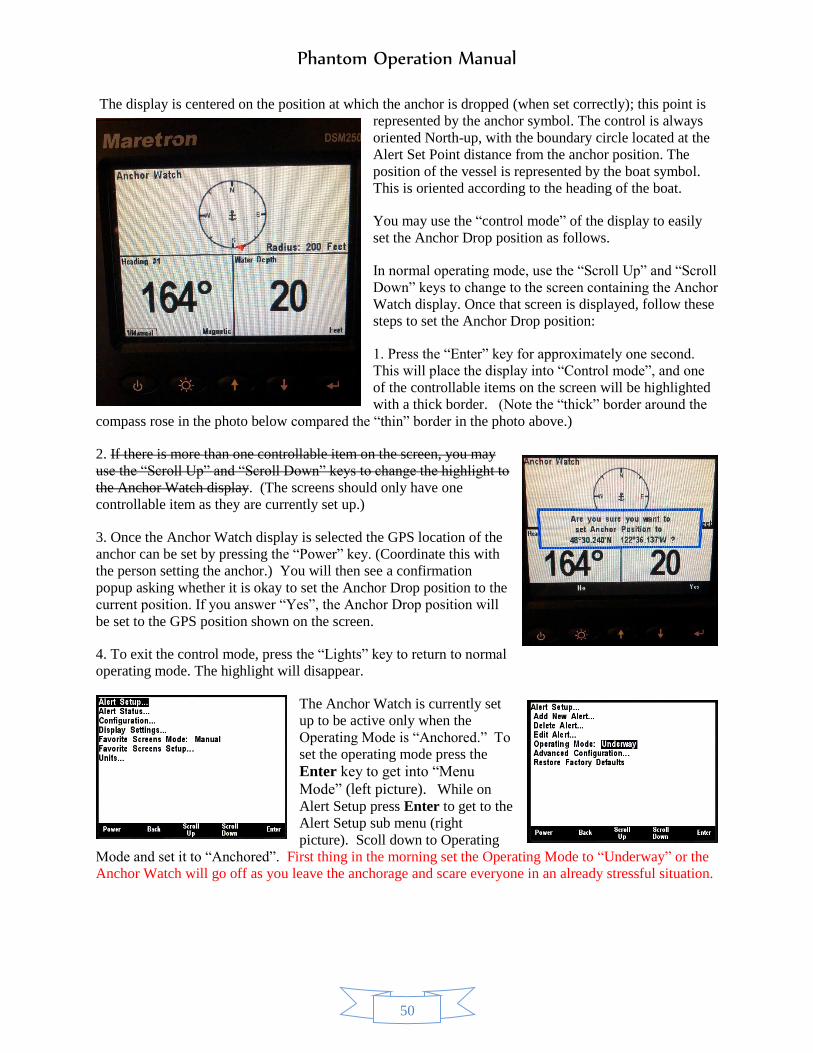
Phantom Operation Manual
50
The display is centered on the position at which the anchor is dropped (when set correctly); this point is
represented by the anchor symbol. The control is always
oriented North-up, with the boundary circle located at the
Alert Set Point distance from the anchor position. The
position of the vessel is represented by the boat symbol.
This is oriented according to the heading of the boat.
You may use the “control mode” of the display to easily
set the Anchor Drop position as follows.
In normal operating mode, use the “Scroll Up” and “Scroll
Down” keys to change to the screen containing the Anchor
Watch display. Once that screen is displayed, follow these
steps to set the Anchor Drop position:
1. Press the “Enter” key for approximately one second.
This will place the display into “Control mode”, and one
of the controllable items on the screen will be highlighted
with a thick border. (Note the “thick” border around the
compass rose in the photo below compared the “thin” border in the photo above.)
2. If there is more than one controllable item on the screen, you may
use the “Scroll Up” and “Scroll Down” keys to change the highlight to
the Anchor Watch display. (The screens should only have one
controllable item as they are currently set up.)
3. Once the Anchor Watch display is selected the GPS location of the
anchor can be set by pressing the “Power” key. (Coordinate this with
the person setting the anchor.) You will then see a confirmation
popup asking whether it is okay to set the Anchor Drop position to the
current position. If you answer “Yes”, the Anchor Drop position will
be set to the GPS position shown on the screen.
4. To exit the control mode, press the “Lights” key to return to normal
operating mode. The highlight will disappear.
The Anchor Watch is currently set
up to be active only when the
Operating Mode is “Anchored.” To
set the operating mode press the
Enter key to get into “Menu
Mode” (left picture). While on
Alert Setup press Enter to get to the
Alert Setup sub menu (right
picture). Scoll down to Operating
Mode and set it to “Anchored”. First thing in the morning set the Operating Mode to “Underway” or the
Anchor Watch will go off as you leave the anchorage and scare everyone in an already stressful situation.

Phantom Operation Manual
51
Ultra Trip Hook
If someone sets their anchor across your anchor line you can use the Ultra Trip Hook to get free. It is
stored behind the flat fender in the line locker behind the Portuguese Bridge. The “instructions” for use
are in
C:\Phantom\Equipment Manuals\Ultra Chain Grab\UltraTripHook_Brochure.pdf. You could probably
use the mooring lines in the starboard bow locker as the two lines to operate the hook. You might also
check out the crab pot lead line as one of the lines.
Mooring Buoys
The State Park Sticker on your vessel allows you to pick up the MOORING BUOYS in the parks for free.
You only need to register at the kiosk usually located at the heads of the docks. State mooring cans have a
metal triangle at the top (usually) upon which is a metal ring. They also have a plate on them which states
the number of boats that can be attached to the buoy. Phantom is the largest Selene that can be attached to
a State Parks Buoy. (If asked, she is 43’ – the max is 45’.) If you get caught in a strong blow (30 + knots)
you are better off on the anchor rather than a mooring buoy.
There are two white “manila” lines in the starboard bow locker that are used for mooring lines. Please DO
NOT use docklines. One or both of these lines are run through the metal ring on the top of the buoy and
then over the SPARE BOW ROLLER back to the port side of the Sampson Post where they are cleated off.
Don’t create a “bridle” by cleating off one end to each of the forward cleats. (Yes, I know. That is what
all the books say to do.) If you use the cleats the lines rub on the bottom paint and you can run over the
buoy. If you run both sides of the line(s) over the spare bow roller the boat will stay away from the buoy
and the lines will stay away from the boat.
Picking up buoy
In the summer, buoys are hard to get. Usually they free up about 10 AM and are often gone by noon.
You should plan your movement to try to arrive at the anchorage about 10 AM and be prepared to lurk
until someone leaves. If you are pulling the dingy bring it up to the swim step so you don’t suck one of
the lines into the stern thruster.
Review the operating instructions for the Happy Hooker contained in Appendix D. Set up the steering
station at the bow. Get two helpers who will operate at the bow on the port side. Life
vests are a good idea for everyone on the deck. Pull the two manila lines out of the
starboard bow locker. Pull the “happy hooker” out of the locker (right). Get the boat
hook out of the starboard locker (or grab the one in the cockpit). Grab the deck brush
from the after, port side of the salon wall in the cockpit. Take the brush off the pole and
put the happy hooker on. Attach one end of a manila line to the Samson Post leaving
very little excess behind the cleating. Attach the other end of the manila line to the
paracord attached to the happy hooker (double sheet bend). Make sure it is all set up
correctly so the manila line will lead cleanly over the spare bow roller.
Come up to the buoy into the wind or current as you would for anchoring. Use the thrusters and throttle to
hold the boat so the buoy is about three feet forward and slightly to port of the bow. Have crew members
on the port side of the bow, one with a boat hook and one with the happy hooker. Hook the ring on the
buoy and hold it upright so the crew with the happy hooker can get the mooring line through the ring. Lead
both legs over the spare bow roller and adjust the length of the mooring line so there is very little slack in
it. Cleat the free side of the mooring line off on the Samson Post. It is recommended that you add the
second mooring line. (Think of it as a sleep aid.) You can hold the ring up with the first mooring line and
Phantom Operation Manual
52
use the happy hooker to run the second line. Stow everything. After shutdown, take the dingy to shore and
register or just wait until the ranger comes by and growls at you (sometimes they are nice).
Releasing buoy
This is where being on a buoy really pays off. Stow everything and make the boat ready to go. Engine on
idle and neutral. Let go of one side of each mooring line while making sure the other side is still attached
to the Sampson Post. Pull the lines aboard and stow them in the starboard locker. On to the next
adventure.
CANVAS
There is a system.
All the canvas is marked with its location and an “up” indicator. You will probably only be concerned
with the canvas for the pilothouse windows, the flybridge dash, and the flybridge settee. You might use
the BBQ cover, the flybridge table cover, and the dingy cover.
You can store the canvas on the pilot berth or in the commissary while it is not in use.
Pilothouse Windows
There is blue opaque canvas and brown translucent canvas for the pilothouse. You will want to use the
translucent canvas when not mooring as it keeps the sun from baking you in the pilothouse. Do not have
any canvas on the pilothouse windows when underway. The brown canvas should be rolled up on the
pilot berth with the open side of the snaps exposed. Rolling it makes it easier to install. Start with which
ever side is the outer part of the roll (port or starboard). Snap the top snaps as you unroll the canvas while
leaving the bottom snaps undone. DO NOT LIFT THE WIPERS LIKE AN AUTOMOBILE. They break
if you do that. Raise them about 1” off the glass and slide the canvas under them. Because you are
working with the roll this can easily be done by one person. After you have snapped all the top snaps go
back and snap all the bottom snaps. You will have to stretch the canvas for some of the snaps. Reverse
the process to remove the canvas. When you unsnap the first top snap, roll the canvas such that the after
seam rolls AWAY from the window to start. That way when you get to the other side you will have a
neat roll when the last snap is undone.
The brown canvas will allow you to look out at the world during the day while remaining mostly hidden.
It will reverse at night and allow the world to look at you while you cannot see out if any lights are on in
the boat. You will probably want to replace the brown canvas with the blue canvas at night in a marina.
Flybridge Dash
Please cover the instruments with the plastic covers and put the white canvas on the flybridge dash when
you are done using it. You can run with the canvas bunched just forward of the flybridge dash by
undoing the bungies, unsnapping the twist lock on the helm, and unsnapping ONE of the sides where they
are snapped to the dash.
Flybridge Settee
There is a trick. Unsnap the lower snaps first starting by the BBQ. After you have a few unsnapped you
can pull the canvas up on the seat, put a knee on the seat with the loose canvas in front of you (don’t kneel
on it) and work your way around the settee. When you get to the after part of the settee you can unsnap

Phantom Operation Manual
53
the top while moving backwards or slide out and unsnap the top from the BBQ to the stern. You should
cover the settee every night or the dew will make for some wet bottoms in the morning. To cover the
settee, look at the back of the canvas to figure out what is up and what is forward (or aft). Flop the canvas
over the back of the settee and move around the settee from the BBQ aft snapping only the top snaps
while keeping the loose canvas pushed to the back of the settee. Right leg kneeling on the settee; left leg
jammed between the table and the settee. After the top is snapped, pull the slack canvas over the seat of
the settee and snap the bottom snaps without kneeling on the seat.
SETTEE CUSHION WARNING: If you decide to remove the cushion backs be aware they are held in
place by Velcro straps. If you pull on the cushions you will rip the straps off the cushions. Undo the
Velcro straps first. All the bottom cushions are snapped down.
BARBECUE
The BARBECUE is in the port cabinet on the flybridge. Lift the (heavy) white fiberglass cover and lean it
against the railing. Raise the stainless steel cover and lock it in place. To lower it you will have to lift
slightly and pull the brace towards you. Open the locker doors and turn on the propane. Get a firestick out
of the drawers in the salon to light the BBQ. To light push the black knob down and rotate it while holding
a lighted firestick near the burners. Adjust the intensity by rotating the knob. There are two large tweezers
(or forceps) in the front of the silverware drawer (unless they have been moved). These are really handy
for turning anything on the BBQ.
After use turn off the BBQ using the black knob and turn off the propane bottle. Wait until the grill cools
before closing the stainless steel and fiberglass covers. Please clean up the grill after use.
DINGHY & OUTBOARD MOTOR
Your Walker Bay Genesis Deluxe 301DX DINGHY with a 15 hp Honda engine is stored on the flybridge.
It has a capacity of about 1350 pounds (motor, equipment, and 4 people). It is a precision fit on the flybridge
so take your time.
Remove the canvas cover by undoing the two “cam cleat” style plastic line holders on the port side of the
dingy. Pull the line up to release it from the cam cleat and pull it out of the little hole. Leave the cleat
attached to the canvas. If you cover the dingy you will pull the line through the hole from the back and
cleat it just like a jib sheet (pull down into the cam cleat). Store the canvas forward on the clear chart table
temporarily.
Getting the dingy off and on the boat takes some time. It is recommended that you tie up to a linear dock
with the lines to port and take the dingy off the starboard side. It can go off the port side, but it is easier to
use the starboard side. Talk to your fleet captain about dropping the dingy at the beginning of the trip and
towing it. If the wind is blowing hard or there are big waves it is best to have the dingy on the flybridge
and tied down.
Deploying
Preparation Remove the ensign and stow on the pilot berth or elsewhere. Insert the drain plug into the drain hole and
tighten. Set up the winch and boom controls which should be stored in the large blue padded bag. There
is a “W” on one handle and a “B” on the other handle. W is for Winch and B is for Boom. The plug in
for the controls is on the starboard wing of the flybridge. There are markings (single line and double line)

Phantom Operation Manual
54
to make sure the W goes in the winch outlet and the B goes in the Boom outlet. After setup, quickly
pulse the winch OUT to make sure they are in the right sockets. Lead the electric lines to the port side of
the flybridge AFT of the mast (so you have lots of slack). Turn the helm seats to face backward so you
have more room to maneuver. Release the courtesy flag halyard from the mast (small “white” line on
starboard side of mast running from spreaders to cleat) and let it hang. Undo the three straps that hold the
dingy down and stow them in the (large blue padded) bag. Note the way the after two straps are crossed
to keep the dingy from rolling. Also note how they are lead through the Weaver Chocks so you can run
them again when you tie the dingy down. Click one or both of the yellow lines onto the stainless eye
outside the bow of the dingy. Install the 3-point lifting harness (grey lines with stainless snap hooks in
the “bag”). There are two stainless eyes on the inside of the transom and one eye inside the bow for the
harness. When it doesn’t go in so everything leads cleanly take it off and redo it. Hold up the ring by
hand and make sure everything leads cleanly. Let the winch out a little, undo the snap hook from the
winch, and hook it into the ring on the harness between the two aft lines. Take up most of the slack to
hold the harness up off the boat. The harness and winch line are made of Dyneema which is very smooth
and will not snag you like wire line. You can hold them and let them run across your hands. Drop the
boom a few inches and release the snap shackles on the after rails if you are not rolling much. If you are
rolling you can keep the boom from swinging by leaving the port snap shackle in place and leading the
starboard control line OUTSIDE the shrouds to the D-Ring on the forward starboard side of the railing.
You will have to loosen the control lines to do this. Red is the Port line. Not Red (couldn’t find green) is
the Starboard line. Using the control lines will keep the boom from swinging and dampen the motion of
the boat, but it requires careful and continuous line handling. Only do this if necessary. Assign one
person on the flybridge to keep the dingy from rotating as it is moved. They should keep their hands
apart, touching the port tube and be more like the immovable object than the irresistible force. (Just use
enough force to stop the rotation.) They can also use the yellow line to help control the dingy. Assign
another person to be ready to do the same on the main deck. OK. We are now ready for the fun.
Execution You can always stop the winches by letting go of the switches. Make sure everything is leading cleanly.
If not STOP and fix it. Move slowly.
Raise the boom and let out the winch, either simultaneously or sequentially until the boom is directly
above the ring in the harness. If one of the winches doesn’t turn get the rubber hammer out of the toolbag
and vigorously beat on the winch while holding the lever down. You should not have to do this, but it can
happen if the winches are not used for a long time. Once the boom is directly above the ring you are
ready to raise the dingy off the chocks. Leave the boom alone and raise the dingy straight up. Have your
crew keep it from rotating. After lifting it up a couple of feet, let them experiment with the amount of
force necessary to rotate it. (Not much.). Don’t let the dingy motor hit the back rail. If necessary,
readjust the position of the boom. Continue to lift the dingy until the prop is just above the railing. You
will find that the bow is trying to wedge itself into the crotch between the mast and the shrouds. Move
the dingy aft by (simultaneously) lowering the boom and taking in the winch. You may have to stop and
adjust either the boom or the winch by itself as they take up at slightly different rates. Move slowly and
stay in control. WATCH THE WINCH LINE as the harness nears the block on the end of the boom.
Stop before you hit the splice. I usually rotate the dingy at this point so the bow is headed toward the
swim step. Rotate the boom until the dingy is outboard of the boat. Lower the boom (if necessary) until
it is horizontal. Push the boom against the shrouds and hold it there. Let out the winch until the dingy
hits the water. The person on the deck will keep the dingy from rotating while it drops. Take the yellow
line(s) back to the after hawse hole (DO NOT DRAG THE LINES ACROSS THE TEAK CAPRAIL) and
tie them off. You can either continue to let out winch line until the dingy is behind the boat or use the
boat hook to pull the bridle close to the boat near the side doors and unsnap the winch snap shackle.
Make sure you have the dingy tied to the boat before undoing the winch line.

Phantom Operation Manual
55
Hold the winch line to keep some tension on it and coil up the winch line smoothly. Reattach the boom
control lines to the after D-Rings. Raise the boom until the control lines are just taut. Unclip the bridle
from the dingy and stow in the bag. If you used the control lines to control the boom, coil them neatly
and stow on the mast. Undo the electrical controls, replace the caps, and stow the cables in the bag. If
you want to open up the deck space, unscrew the screws on the Weaver chocks, slide them out of the deck
plates and stow them in the bag. Take note of the way they are oriented so you can replace them the same
way.
Recovery
Recovery is the reverse of the deployment procedure. Take down the ensign and stow it. Let the courtesy
flag halyard loose. Rotate the helm seats to face aft. Make sure the dingy motor is in the down position.
Set up the chocks. Set up the electrical controls. Install the bridle while the dingy is next to the swim
step. Either clip the winch line onto the bridle at the back of the boat or bring the after part of the dingy
forward to the middle hawse hole of Phantom and cleat it off; work through the side door to hook the
winch line to the bridle. Release the boom control lines and lower the boom to horizontal. Swing the
boom out and take in the winch line while holding tension on it with your hand until it is taut. Release all
the lines tying the dingy to the boat. Raise the dingy with the winch until the winch line has about 6” left
above the start of the splice. Have your crew positioned on the main deck and flybridge to prevent the
dingy from rotating. Raise the boom and let out the winch keeping the prop above the railing. At some
point rotate the dingy so it faces forward. Keep raising the boom and lowering the winch until the dingy
comes into the boat. Be careful to get the outboard motor inside the railing before lowering the boat onto
the chocks. Getting the dingy placed right will require some finesse. Have one of the crew get under the
after part of the dingy and guide it onto the chocks. After recovery strap the dingy down, remove the
drain plug, and stow the cables and bridle in the bag. If you are not going to use the dingy again, cover it
and put the light lines through the cam cleats and tighten. The canvas has bow and stern written on the
inside to help with orientation. The seat back should be up to make the cover fit correctly.
Towing
I use the two yellow lines to tow the dingy in a configuration I have never seen on any other boat. Clip
the two snap shackles on the ring on the outside of the bow of the dingy. Run the lines through the
staples to each of the after hawse holes. Cleat the lines so that the chafing gear goes around one horn of
the cleat and through the hawse hole. Use plenty of wraps and lock loops on the cleats as polypropylene
is quite slick. You can hang the excess in the black line hangers. I’ve tried to find the sweet spot, but
Phantom’s wake is quite unusual and I can’t find the third wave in the center of the wake. If you find it
let me know. When you leave an anchorage or come into an anchorage pull both lines up and cleat them
off so the nose of the dingy is against the swimstep. This keeps the lines from getting sucked into the
stern thruster and ruining your week. This is also a good way to keep the dingy at night so it doesn’t
bounce against the hull in the middle of the night. Remember to let it out before increasing rpm’s when
leaving an anchorage. When towing the dingy please raise the prop out of the water so it doesn’t spin.
CRABBING & FISHING
A crab pot with a float and 100’ of lead line are located in the lazarette along with a crab measuring gage.
Always check the fishing and crabbing requirements before you leave on your cruise. You will need a
license. Many areas are CLOSED to crabbing and fishing on certain months. The limit is usually 5 male
crabs per day per license.

Phantom Operation Manual
56
CRAB AWAY FROM THE BOAT! Lines can get wrapped around props. The best way to set the pot is
to put it in the back of the dingy (between the seat and the motor), get away from the boat, attach the line
to the bridle, bait the trap, and drop it in 40’-60’ of water. Fish-flavored cat food or with the pop-up ringed
lids or frozen chicken backs or turkey legs work the best for a nice neat way to bait the trap. You can leave
the pot down for 4-8 hours over slack tide or
overnight. Be certain of water depth before
lowering the crab pot; make certain the buoy line
is long enough for the depth. Measure the crabs
using the CRAB MEASURING GAUGE
normally stored in the crab pot. Keep the male
crabs of proper size (usually 6 ¼ inches across
the carapace). When you go to set your pot take
the white bucket and get your (clean) cooking
water. When you check your pot take a white
bucket for crabs.
Boil crabs about 12 minutes to cook. There is a large stainless steel pot under the port side of the “bench”
in the lazarette that holds the hydraulic ram for steering. It is in a square plastic basket. You will probably
have to pull some things out of the laz to get to it. Please store it upside down so it drains. There is also a
smaller pot under the after chair in the salon. There are crab crackers and picks in the salon drawers.
Cracking crab is messy and best done outside with lots of paper towels and a trash can. The shells and
innards should go overboard as they get really stinky after a day.
After using, wash equipment thoroughly with fresh water (available from the cockpit shower).
Note -- Please let the crab line and pot dry a bit in the cockpit before putting it away in the laz. DON’T
put the line or pots on the teak cap rail!
OTHER: Safety & Bilge Pumps
SAFETY should be paramount in your daily cruising. A MAN OVERBOARD DRILL should be discussed
and perhaps even practiced with a life jacket. Remember your lifejackets are stowed in the starboard cabinet
on the Portuguese Bridge. A few should always be out and ready. Your “flares” (safety light) and safety
equipment are located in the cockpit locker.
Phantom is equipped with several AUTOMATIC BILGE PUMPs. The master switches are located on the
“mimic” panel above the chart table in the pilothouse. Normally, the switches will be left in the AUTO
position. The bilge pumps almost never run. If you hear one running check to see why. There are wooden
plugs near each thru hull and a foam “universal” plug at the port side entrance to the engine room.
An AUXILIARY HAND OPERATED BILGE PUMP located in the cockpit locker. The handle is on the
wall of the cabinet. There is a manifold in the locker that allows you to chose which are is being pumped.
This is used only in emergency situations.
The ENGINE SPARES BOX (plastic orange color) is stowed in the outboard starboard locker in the
commissary. Most other spares are stowed in the outboard port locker in the commissary. Light bulbs are
stowed in the bottom drawer of the cabinet in the Salon.

Phantom Operation Manual
57
THRU-HULL LOCATIONS
The locations of the thru-hulls are noted on the following diagram. There is a single-page laminated
version of this diagram in the chart drawer. There is a wooden plug next to each thru-hull in the unlikely
event the hose comes off, and you cannot close the thru-hull. There is also a universal orange foam plug
at the port-side entrance to the engine room that can be stuffed into any thru-hull or a hole in the hull
smaller than your fist.

Phantom Operation Manual
58

Phantom Operation Manual
59
Appendix A – Electrical Panel Configuration
No. Label Underway Docked Anchored/Moored Comments
0 MAIN 50 AMP ON ON ON Always ON
1 CHARGER HE OFF OFF OFF OFF unless needed to load generator; house, engine
2 CHARGER SBG OFF OFF OFF OFF unless needed to load generator; thrusters, gen
3 REFRIGERATOR OFF ON OFF Only on shore power or gen
4 WATER HEATER OFF ON OFF Only on shore power or gen
5 WASHER/DRYER OFF OFF OFF Only when using; shore power or gen
6 ENGINE BLOCK HEATER OFF OFF OFF Winter storage only
7 HURRICANE HEATER ON ON ON 120 v circulation pump
8 FUEL POLISHING SYSTEM OFF OFF OFF Don’t use it
9 FWD CABIN OUTLET ON ON ON As needed
10 MASTER CABIN OUTLET (SUMP PUMP) ON ON ON Leave on for Sump Pump
11 SALON OUTLET ON ON ON As needed
12 PILOT HOUSE OUTLET ON ON ON As needed
13 MICROWAVE OVEN ON ON ON As needed
14 TV/VCR OFF OFF OFF Not Operational
15 GALLEY OUTLET ON ON ON As needed
16 E/R LIGHTS ON ON ON As needed
17 INVERTER INPUT ON ON ON Always ON
18 INVERTER OUTPUT ON ON ON Always ON
19 F/B OUTLET OFF OFF OFF As needed
20 COMPUTERS ON ON ON Always ON
21 FREEZER OFF OFF OFF As needed
22 LAZ OUTLETS OFF OFF OFF As needed
120-volt Panel
No. Label Underway Docked Anchored/Moored Comments
0 MARETRON ON ON ON Always ON
1 GPS ON OFF ON Furuno
2 CELL AMP OFF OFF OFF Not Operational
3 FB VHF ON OFF OFF Turn on on FB unless using
4 VHF ON OFF OFF Simrad
5 CAMERAS (AIS) ON OFF OFF
6 Defrost Fan OFF OFF OFF As needed
7 STEREO ON ON ON As needed
12-volt Panel

Phantom Operation Manual
60
No. Label Underway Docked Anchored/Moored Comments
MAIN 100 AMP ON ON ON Always ON
1 FWD LIGHTS ON ON ON As needed
2 MASTER LIGHTS ON ON ON As needed
3 SALOON LIGHTS ON ON ON As needed
4 GALLEY LIGHTS ON ON ON As needed
5 PILOT LIGHTS ON ON ON As needed
6 E/R LIGHTS ON ON ON As needed
7 COM LIGHTS OFF OFF OFF As needed
8 LAZARETTE LIGHTS OFF OFF OFF As needed
9 EXTERIOR LIGHTS OFF OFF OFF As needed; Activates switch on aft cabinet in Salon
10 COURTESY LIGHTS OFF OFF OFF Outside red walk lights as desired
11 NAVIGATION LIGHTS OFF OFF ON Turn on Anchor light on dash when anchored or moored
12 ENG IGNITION ON OFF OFF
13 ELECTRONIC ENG CONTROL ON OFF OFF
14 SPREADER LIGHTS OFF OFF OFF As needed
15 SEARCH LIGHT OFF OFF OFF Search Light nonop; use handheld
16 REFRIGERATOR ON OFF ON
17 HORN ON OFF OFF
18 WIPERS ON OFF OFF
19 OFF OFF OFF Not Operational
20 WINDLASS ON OFF ON Requires second switch to right of panel to operate
21 FRESH WATER PUMP ON ON ON As needed; Best to turn off when not on boat
22 MACERATOR PUMP OFF OFF OFF
23 OFF OFF OFF Not Operational
24 DECK WASH PUMP OFF OFF OFF Use to wash down anchor and chain; then TURN OFF
25 E/R BLOWER ON OFF OFF
26 TOILET BLOWER OFF OFF OFF Not Operational
27 FIRE BOY ON ON ON Engine Room fire extinguisher; Engine dead unless ON
28 FULL LEVEL ALARM ON ON ON Monitor black water level in master head
29 GAS ALARM OFF OFF OFF ON while cooking; otherwise OFF
30 FWD TOILET ON ON ON
31 MASTER TOILET ON ON ON
32 DC OUTLET OFF OFF OFF As needed
33 RADAR/Sounder ON OFF OFF
34 AUTO PILOT ON OFF OFF
35 GPS OFF OFF OFF Not Operational
36 THRUSTER ON OFF OFF
37 OFF OFF OFF Not Operational
38 SSB OFF OFF OFF Not Operational
39 STABILIZER ON OFF OFF
40 NAUTICAL INSTRUMENTS ON ON ON Analog tank levels in pilothouse
41 OIL CHANGE PUMP OFF OFF OFF
42 CAMERA OFF OFF OFF
43 12V DC PANEL ON ON ON
44 MONITORS ON ON ON
45 GARMIN ON OFF OFF
46 OFF OFF OFF Not Operational
47 C-PHONE OFF OFF OFF Internal phone system with bluetooth; optional
24-volt Panel

Phantom Operation Manual
61
Appendix B – FUEL MANIFOLD
The fuel manifold is set up to draw from the bottom of both tanks through the crossover line into the hose
that goes from the bottom of the port tank to the Racor. The return goes to both tanks. Please don’t
change the valves without a good reason.

Phantom Operation Manual
62
Appendix C – Fuel Burn and Boat Speed
0
1
2
3
4
5
6
7
8
9
0
2
4
6
8
10
12
14
16
18
500 1000 1500 2000 2500 3000
Fuel
Eff
icie
ncy
, nm
/gal
Bo
at
Spe
ed
, kts
& F
uel
Rat
e, g
ph
Engine Speed, rpm
Phantom Fuel Burn, Speed, & nm/gal
Fuel Burn, gph Speed, kts nm/gal

Phantom Operation Manual
63
Appendix D – Happy Hooker Mooring Buoy Grabber