Embed Size (px)
Citation preview

P h E lPushover Example(Appendix C)(Appendix C)
Derrell Manceaux, P.E.
“PUSHOVER” ANALYSIS of a TWO COLUMN BENT
Derrell Manceaux, P.E.Derrell Manceaux, P.E.

Pushover Concept
To find the total deflection a structure can obtain prior to collapse

Pushover Procedure
Push on a structure until an event occurs, calculate properties and continue pushing until next event occurs, ….. continue this iteration until collapsethis iteration until collapse

Pushover Procedure
1) Calculate member properties 1) Calculate member properties 2) Obtain Moment-Curvature for column with axial loads
(max & min). 3) Determine EQ force required to obtain ultimate moment
Keep pushing untilPush until hinge forms
p p gmechanism develops
First hinge Second hinge

Pushover Procedure
4) Determine additional EQ force required to obtain 4) Determine additional EQ force required to obtain rotational capacity
5) Calculate deflections 6) Continue to push until first rotational capacity is
reached-failure 7) Calculate final deflection
Keep pushing untilrotational capacity is reached
Rotation capacity

Example Problem
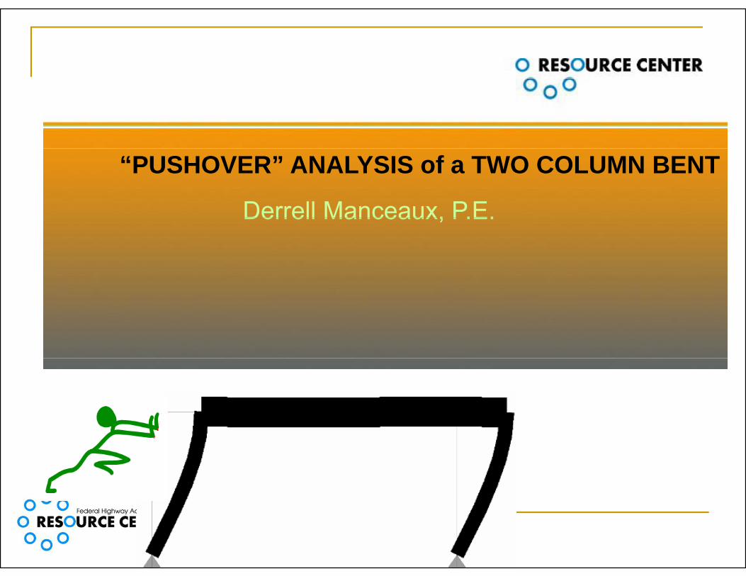
Structure Properties
G t Geometry H=15 ft W=32 ft
DL=1200 k
L=20 ft Plastic Hinge
L =20 inch LpA=20 inch LpB=20 inch Dead Load 15
’20
’
DL=1200 kip
32’32’A B

“Moment-Curvature” for Column- (Dead Load Only)
Axial Dead Load PDL=1200 k PDL= 600 k/column
Yield Moment=Ultimate MomentM M 1600 k ft
My Mu
My=Mu=1600 k-ft Yield Curvature
Ø =140x10-6/inch Øy 140x10 /inch Ultimate Curvature
Øu=2350x10-6/inchu
Øy Øu

Iteration 1-Determine EQ force required to obtain Yield Moment for DL only
Apply Unit Load and Take Ratios Apply Unit Load and Take Ratios M=7.5 k-ft with unit load
EQ 1600/7 5 213 3 ki EQ=1600/7.5 = 213.3 kip
My=1600 k-ft
7.5
A B

Revise axial loads for EQ force being applied
EQ x L = PEQ x w 213.3 x 20 = PEQ x 32 PEQ=± 133.33 kip
Pcol A= PDL - PEQ
Pcol A = 600 - 133.3 = 466.7 kcol A
Pcol B= PDL + PEQ
A B
col B DL EQ
Pcol B = 600 + 133.3 = 733 k

Obtain Moment-Curvature for column with revised axial loads
C l “A” Column “A” Axial Load=466 kip
Yield Moment=Ultimate Moment Yield Moment=Ultimate MomentMAy=1265 k-ft
Yield Curvature Yield CurvatureØAy=138 x 10-6/inch
Ultimate Curvature Col B Ultimate Curvature
ØAu=2500 x 10-6/inch EIA= MAy / ØAy
Col A
A Ay Ay1265 x 12/138 x 10-6
=1.1 x 10⁸ k-in2
Øy Øu

Obtain Moment-Curvature for column with revised i l l daxial loads
C l “B” Column “B” Axial Load=733 kip
Yield Moment=Ultimate Moment Yield Moment=Ultimate MomentMBY=1670 k-ft
Yield Curvature Yield CurvatureØBY=143x10-6/inch
Ultimate Curvature Col B Ultimate Curvature
ØBu=2200x10-6/inch EIB= MBy / ØBy
Col A
B By By1670 x 12/143 x 10-6
=1.4 x 10⁸ k-in2
Øy Øu

Iteration 2-Determine EQ force required to obtain First Yield in Column “A”Apply unit load to determine linear ratios (scale Apply unit load to determine linear ratios (scale factor).
Determine moment diagram with unit load Determine moment diagram with unit load. EQ1=MAY/7.5=1265/7.5= 168.67 kip
7.5

Calculate deflection at first yield
3 Δ1= EQ1 x (h x 12)3
3 x (EIA + EIB) Δ1
Δ1 = 168.67 x (15 x 12)3 = 1.31 in3 x (1 1 + 1 4) x 1083 x (1.1 + 1.4) x 108
K 3 EIΔ
Basic stiffness formula for deflection Fix-Pin condition:
A BK=3 EIΔL3

Keep Pushing until Second Hinge FormsKeep Pushing until Second Hinge FormsDetermine additional EQ force required to obtain yield moment in second columnobtain yield moment in second column Reserve capacity in column “B”= Mreserve B=MBY- MAY=1670-1265=405 k-ft
A B

Determine additional EQ force required toDetermine additional EQ force required to obtain yield moment in second column
Place pin in col “A” and apply unit load Determine EQ2 with ratios: Determine EQ2 with ratios: EQ2=Mreserve B/15 = 405/15 = 27 kip
M=15M=0
A B
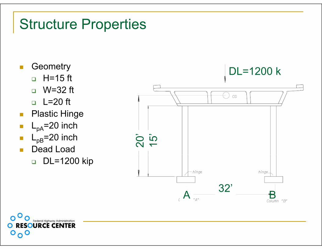
Calculate additional deflection for second hinge in Col ‘B’
EIB = 1.4 x 10⁸ k-in2
Δ EQ x (h x 12)3 Δ2 Δ2= EQ2 x (h x 12)3
3 x EIB
2
Δ2 = 27 x (15 x 12)3 = 0.37 in3 x (1.4 x 108)
A B

Failure is assumed when a plastic hinge reaches rotational capacity
Column ‘A’-Rotational Capacity
Yield Curvature ØAy=138 x 10-6/inch
Col B
Col A
Ultimate Curvature ØAu=2500 x 10-6/in θpA=LpA x (ØAu - ØAy)pA pA Au Ay
θpA= 20 x (2500-138) x 10-6
= 0.047
Øy Øu

Failure is assumed when a plastic hinge reaches rotational capacity
Øy ØuØy Øu

Failure is assumed when a plastic hinge reaches rotational capacity

Failure is assumed when a plastic hinge reaches rotational capacity
Column ‘B’-Rotational Capacity
Yield Curvature- ØBy=143 x 10-6/inch
Ultimate Curvature- ØBu=2200 x 10-6/in
θpB=LpB x (ØBu - ØBy) θpB= 20 x (2200-143) x 10-6
Col B
Col AØy Øu θpB 20 x (2200 143) x 10 = 0.041
Col AØy Øu

Following the formation of the second hinge, the rotational capacity of Column ‘A’ was reduced: θA Reduced= Δ2/ (h x 12-0.5LpA) θA Reduced= 0.37/ (15 x 12-10)= 0.0021A Reduced
And the remaining rotational capacity in column ‘A’ is:
θA Remaining = θpA - θA Reduced
controls
A Remaining pA A Reduced
θA Remaining = 0.047-0.0021 = 0.045 > θpB = 0.041

C ti t h til fi t t ti lContinue to push until first rotational capacity is reached:Δ3= θpB (h x 12-0.5LPB) = 0.041(15 x 12-10) = 6.97 in
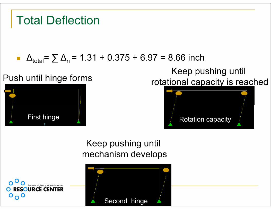
Total Deflection
Δtotal= ∑ Δn = 1.31 + 0.375 + 6.97 = 8.66 inch
Push until hinge formsKeep pushing until
t ti l it i h dPush until hinge forms rotational capacity is reached
First hinge Rotation capacity
Keep pushing untilmechanism developsmechanism develops
Second hinge
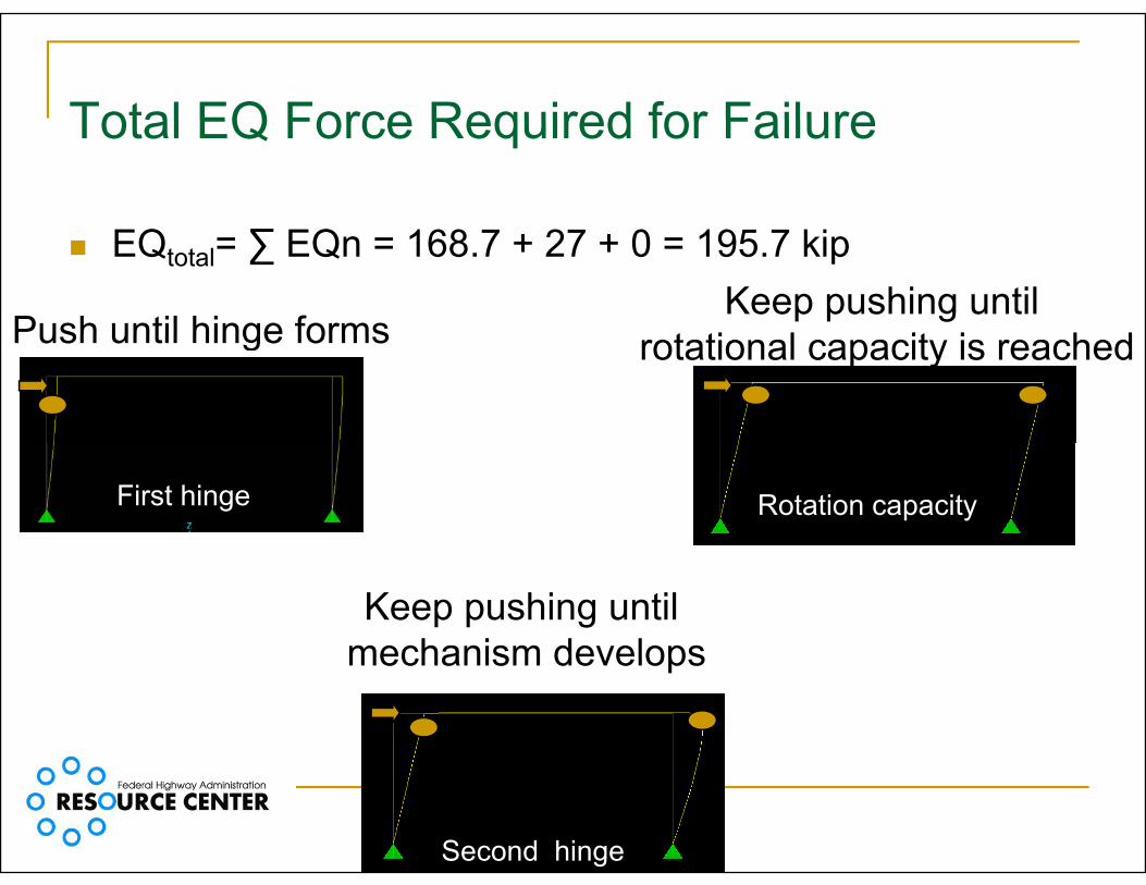
Total EQ Force Required for FailureTotal EQ Force Required for Failure
Push until hinge formsKeep pushing until
t ti l it i h d
EQtotal= ∑ EQn = 168.7 + 27 + 0 = 195.7 kip
Push until hinge forms rotational capacity is reached
First hinge Rotation capacity
Keep pushing untilmechanism developsmechanism develops
Second hinge

Ductility Factor – “R”
R Δ / Δ R = μ = Δtotal/ Δyield
R = μ = 8.66 / 1.31 = 6.6 Δyield Δtotal
Note:AASHTO “R” factor for multi column bent is 5
Summary
Understand concept and procedure of performing a Pushover AnalysisT fi d th t t l d fl ti t t bt i i t To find the total deflection a structure can obtain prior to collapse

Describe the “Pushover” Procedure
Push until hinge forms
Keep pushing untilrotational capacity is reachedg
First hinge Rotation capacity
Keep pushing untilmechanism developsmechanism develops
Second hinge