Embed Size (px)
Citation preview

Journal
Paper
Introduction
Impala Platinum’s Base Metals Refinery inSprings gets its raw material from thecompany’s mining, concentrating, smeltingand converting facilities in Rustenburg. TheBMR then removes as much of the base metalsas possible and sends the PGM (platinumgroup metals) concentrate to the PMR plant forfurther processing. The base metals are refinedand sold separately to maximize theconversion of raw material into revenue(Figure 1).
A background to first stage leach
The aim of the first stage leach process is tomaximize the dissolution of nickel, cobalt andimpurities and to leave copper and PGMs in thesolids for treatment in the second stageprocesses. The subsections that follow describethe first stage leach process together withprocess chemistry and the process challenges.
Process description
Figure 2 shows a flow diagram of the firststage leach process. The matte from the
mineral processing plants is fed with deminer-alized water to the ball mill to increase thesurface area of the particles for leaching. TankTK2100 serves as a buffer tank for the millingoperation and the feed tank to the first stagecircuit. Pulp density is adjusted in tankTK2102 with spent electrolyte solution. Thespent electrolyte solution is return solutionfrom the copper electrowinning section.
The slurry from tank TK2102 is pumped tothe first compartment of the autoclave.Currently two autoclaves operate in parallel.Steam is added to the first compartment tomaintain the required temperature and oxygenis added to maintain pressure as well as tooxidize the sulphides to sulphates in thepresence of sulphuric acid from the spentelectrolyte. The spent electrolyte also serves tocontrol pH in the autoclave.
The overall reaction mechanism couldroughly be divided into three stages (asdetermined by batch leaching experiments byRademan, 1995) where the major reactionsoccurring in each stage of the leaching processdiffer, i.e.:
➤ Stage I (10–40 minutes)—thecementation of copper and the leachingof nickel from the alloy phase and out ofthe Ni3S2 phase. Refer to reactionsEquations [1]–[7] as determined byRademan (1995) and Rademan, et al.(1999)
[1]
[2]
pH advanced process control solutionfor Impala BMR first stage highpressure acid-oxygen leachby A.F. Khan*, T. Spandiel*, T. van Schalkwyk†, and J.A.M. Rademan‡
SynopsisThe CSense advanced process control (APC) solution’s mainobjective was to improve the stability of the pH in the first stageleach process thereby improving nickel and iron extractionefficiencies and reducing the base metal (BM) content in theplatinum group metals (PGM) concentrate. By improving thestability of the control of the pH on the first stage leach it had thecorresponding effect of improving the Ni extraction efficiency by0.5% and the Fe extraction efficiency by 3.3%. The system relievedthe operators of many decisions that were virtually impossible tomake given the complex, variable and real-time nature of theprocesses in their charge. On the operational side, the operatorsunderstand the APC system and they trust it. Another benefit is thereduction in pH peaks in the autoclave, which can oxidize certainelements whereby they become difficult, if not impossible, to leach.These elements go right through the process and end up contami-nating the PGM solids, with the result that the entire batch has to berecycled through a lengthy and costly processing pipeline.
* Impala Platinum Ltd.† Blue Nickel Solutions CC‡ CSence Systems (Pty) Ltd© The Southern African Institute of Mining and
Metallurgy, 2009. SA ISSN 0038–223X/3.00 +0.00. This paper was first published at the SAIMM Conference, Hydrometallurgy 2009, 24–26 February 2009.
365The Journal of The Southern African Institute of Mining and Metallurgy VOLUME 109 NON-REFEREED PAPER JUNE 2009 ▲
51-60:Template Journal 7/1/09 8:56 AM Page 365

pH advanced process control solution for Impala BMR
[3]
[4]
[5]
[6]
[7]
➤ Stage II (40–160 minutes)—the selective leaching ofnickel to form various Ni-S mineral phases and thesimultaneous leaching and cementation of copper toform the various Cu-S mineral phases. Refer toEquations [8]–[13] as determined by Rademan (1995)and Rademan, et al. (1999).
[8]
[9]
[10]
[11]
[12]
[13]
➤ Stage III (160–300 minutes)—the simultaneousleaching of nickel (to form NiS and Ni3S4) and copper(to form and CuS). Refer to reactions Equations[14]–[18] as determined by Rademan (1995) andRademan, et al. (1999).
[14]
[15]
[16]
[17]
CuS is oxidized by O2 (Equation [18]) to form Cu2+ andSO42-.
[18]
The principal reactions occurring in the initial stages ofthe first stage leach are the reactions of nickel alloy (Ni) andheazlewoodite (Ni3S2) with sulphuric acid (H2SO4) and Cu2+
in solution in the presence of oxygen (O2) to form coppersulphide and nickel sulphate.
For control purposes the process needs to be controlled asclose to the end of Stage II as possible at all times.
Process challengesThe required iron (Fe), an impurity, in the matte is below 1%.However, matte batches delivered to the BMR sometimeshave more than 1% Fe. The Fe needs to be leached in the firststage process and is then removed in the jarosite circuit.When this does not happen, the Fe finds its way to the PGMcircuit where it is very difficult to leach out and thereforeconstrains the downstream processes.
The problem experienced in the first stage leach processis that the process controllers are not always able to copeefficiently with the apparently capricious behaviour of theprocess. This could be due to:
▲
366 JUNE 2009 VOLUME 109 NON-REFEREED PAPER The Journal of The Southern African Institute of Mining and Metallurgy
Figure 1—A simplified flow diagram of Impala’s processes
Figure 2—First stage leach process flow diagram
51-60:Template Journal 6/25/09 12:08 PM Page 366

➤ A lack of sufficient understanding of the critical controlelements of the process
➤ Having to cope with plant emergencies andbreakdowns and not being able to closely monitor theprocess (specifically pH), and
➤ The fact that they have, most of the time, two processesto monitor continuously, i.e. two autoclaves.
Most of the process controllers control the process byexperience and feeling, which inherently means that differentoperators will control the process differently. Therefore, thiscauses an unstable process from the one shift to the next.
Nickel (Ni) in the matte is in the region of 47% and isprimarily leached in the first stage process. Therefore it iscrucial to have a high Fe and Ni extraction efficiency in thefirst stage leach process. It is known that pH in the region of1.8 and 2.2 serves to offer good extraction efficiencies. pHwas manually controlled by process operators with someshifts performing better than others. Considering the myriadreactions taking place in the first stage leach process as wellas the other control variables, the challenge was to control pHwithin the specification limits in real time.
Samples are taken hourly from compartment nos. 1 and 4of the autoclave for analysis of the metals content (Ni, Cu andFe). pH samples are taken at shorter intervals to determinethe pH of the pulp in these two compartments because it isthe primary control variable. Depending on the pH, theoperator will vary the spent electrolyte flow rate to theautoclave or adjust the pulp flow rate to the autoclave. Incertain instances the operator will also increase the pulpdensity in the feed to try and make up for lost production tothe detriment of the efficiency of the process.
The performance improvement design
A feasibility study was conducted to define the boundaries ofthe problem, assess current status and to present a solutiondesign before starting with the implementation.
Feasibility study
The problem experienced in the first stage leach process isthat the process controllers are not always able to copeefficiently with the apparently capricious behaviour of theprocess. To provide the context of the complex behavioureach parameter used as part of the solution and its effect onthe process are briefly discussed below:
Process disturbance variables
➤ Matte composition—the variation in the composition(amounts of the different elements) in the feed mattewill have an effect on the leaching process to a varyingdegree, depending on the actual increase or decrease ofa specific element. For example, if the feed mattecontains a higher concentration of iron (Fe) it willresult in a higher concentration of iron, in either theleach discharge solution or in the solids (depending onthe control efficiency of fist stage leach).
➤ Spent electrolyte solution composition—variationsoccur in the acid concentration of the spent electrolytesolution coming from the copper electrowinningsection, as well as in the concentration of other ionic
species (Ni, Cu, Fe, Co, etc.). The variation in the acidconcentration will influence the rate of chemicalreactions taking place in the autoclave. The variation inthe ionic species will have the same effect on theleaching process as does the variation in the mattecomposition. Furthermore, it is possible thatammonium ions (NH4+) in the spent electrolytesolution will form jarosite precipitates under high pHconditions in the first stage leach, making it almostimpossible to leach out in the latter stages of theprocess, and it will eventually result in high Fe in PGM(platinum group metals) concentrate product to PMR(platinum metals refinery).
➤ Pulp feed rate—the feed rate to the autoclave should beset at a setting that is believed to be the optimum forthe maximum throughput while obtaining the desireddegree of leaching. Currently the feed rate is sometimesvaried by the operator, to help to get the pH within therequired control range more quickly, but mostly whendownstream bottleneck conditions occur.
Process state variables
➤ Pulp density—the pulp density is a very importantfactor in the reaction kinetics of the pulp, because forlower or higher pulp densities the leaching will eitherbe more, or less efficient. More importantly, this willaffect the pH in the autoclave. Ultimately the pulpdensity in the first compartment in the autoclave needsto be controlled. The design requirement was for a pulpdensity of minimum 1.35 kg/m3 to a maximum of 1.50 kg/m3 in the autoclave. A too high pulp densitywill result in high pH values and too low pulp densitywill result in too low pH values.
➤ Cu in solution—the Cu in leach solution is necessary forthe cementation reaction with metallic Ni, but anoversupply of Cu in solution negatively affectsdownstream processes. The Cu in solution is primarilysupplied via the spent electrolyte that can contain highconcentrations of Cu.
Adjustable variable
➤ Spent electrolyte flow rate—the spent electrolyte flowrate to the autoclave is the primary variable to controlthe pulp density and indirectly the pH in the autoclave.The spent electrolyte flow rate is also adjusted by theoperator to achieve the desired pH in the firstcompartment of the autoclave that ultimately influencesthe performance of the process.
Target variable
pH in 1st compartment of autoclave—the pH in the firstcompartment of the autoclave is controlled by the addition ofspent electrolyte solution to the autoclave. Furthermore, it isassumed that if the pH (and pulp density) in the firstcompartment is correct and the standard process conditionsexist, the pH in the fourth compartment will be correct.
Therefore, the primary parameters, from the above list,that lead to variation of the pH in the first stage leach are:
➤ Pulp density➤ Spent electrolyte flow rate to the autoclave➤ Pulp feed rate to the autoclave.
pH advanced process control solution for Impala BMRJournal
Paper
367The Journal of The Southern African Institute of Mining and Metallurgy VOLUME 109 NON-REFEREED PAPER JUNE 2009 ▲
51-60:Template Journal 7/1/09 8:57 AM Page 367

pH advanced process control solution for Impala BMR
PID control loopsProportional-integral-derivative (PID) control loops aresingle-input single-output controllers based on first orderLaplace transform calculations. PID loops are the norm forforming the base layer control of any industrial plant.Therefore, it is important to ensure that PID control is used asfar as possible, and that the current PID control is maintainedproperly.
Sampling and measurementA key requirement for implementation of automatedadvanced process control (APC) solution is that the targetmeasurement is available online and timeously. An online pHsampling system has been developed by Impala in house, asshown in Figure 3.
pH sampling sequence:➤ Sample and the drain valves open for 3 seconds➤ The drain valve closes but the sample valve remains
open for a further 4 seconds➤ Sample valve closes➤ All valves remain close for 50 seconds giving the
solution in the pot time to settle and the pH transmitteropportunity to read the sample value
➤ The reading from the transmitter is stored into thecorrect PLC address location for the time of sampletaken. (Each time interval sample for the 10 minutesequence has its own address allocated and displayedon Scada)
➤ The drain and flush valves open simultaneously for 6seconds, flushing out the sapling pot
➤ Drain valve closes but the flush valve remains open foranother second before closing
➤ The pot should now be filled with water waiting for thenext sample to be taken.
The sampler sequence is triggered from the PLC clockevery 10 minutes, starting on the hour.
Performance benchmarkThe average pH and standard deviation values for theautoclaves 2110C and 2110D are shown in Table I. Theaverage pH in the first compartment of both autoclaves is
acceptable, but the problem is rather the high standarddeviations, i.e. > 1. The high standard deviations are also anindication of the reactive control that operators have to use tobring the pH back to the target value, which is roughlyaround 2.0. The average pH in the fourth compartment ofautoclave 2110D poses a problem as this average of 3.4 isexcessively high and will lead to insufficient leaching(Rademan, 2005). This ‘unleached’ material is thenpropagated through the circuit to the final PGM concentratethat is sent to the PMR.
Figure 4 is an indication of the distribution of the pHvalues in the first compartment of autoclave 2110C (top) and2110D (bottom). The objective of the proposed pH controlsystem would be to reduce the tailing of the pH to the highside (as marked on graph). The reduced variation in pH inthe first compartment should lead to reduced pH variation inthe fourth compartment. The pH in the fourth compartment ofthe autoclave is a direct result of the pH in the firstcompartment.
If one analyses the average pH values with the dailyextraction efficiencies for Ni, Cu and Fe, certain trends can berecognized:
➤ The lower the average pH value the higher the Niextraction
➤ A large difference between the pH average on the #1and #4 compartments result in a low Fe extraction
➤ A low Fe extraction gives rise to a high Cu cementationrate (high negative value).
The lower the average pH value, the higher the Niextraction. This confirm the findings by Rademan (1995) thatfor higher acid concentrations, the higher the Ni extraction.
▲
368 JUNE 2009 VOLUME 109 NON-REFEREED PAPER The Journal of The Southern African Institute of Mining and Metallurgy
Figure 3—Picture of actual pH sample pot arrangement on the autoclave
Table I
pH averages and standard deviations for autoclave2110C and 2110D
2210C 2210D
Average pH #1 2.2 2.4Standard deviation pH #1 1.16 1.23Average pH #4 2.3 3.4Standard deviation pH #4 0.82 1.49
51-60:Template Journal 6/25/09 12:08 PM Page 368

Therefore, Ni extraction is purely a function of acid concen-tration or pH. A negative outcome of too high acid concen-tration is that Cu might start leaching, i.e. the kinetics for Cuextraction will increase.
A large difference between the pH average on the #1 and#4 compartments result in a low Fe extraction. This is aneffect caused by unstable pHs were the operator has todecrease the pH in the first compartment significantly toquickly get the pH in the fourth compartment under control.This leads to an excessive amount of spent electrolyte beingadded in the first compartment, where the Cu in solution hasto be cemented first before any significant Fe leaching canoccur. The end result is that only Cu cementation occurs withthe associated Ni leaching, but not much Fe is leached in theprocess. This then results in the phenomenon where a low Feextraction gives rise to a high Cu cementation rate (highnegative value).
The objective is to improve the pH control on the firststage leach process. The first step is to stabilize the control asfar as possible by trying to avoid significant pH variations.The second step is to optimize the process to increasethroughput and improve quality.
Control philosophyBased on the results and discussions above, a practical andlow risk control solution can be developed. However, incertain areas it will also require a change in the currentoperating philosophy. In principle the philosophy is toautomatically manipulate the spent electrolyte flow rate viathe controller, leaving the pulp feed rate to the autoclave as avariable that the process controller can adjust.
The proposed control philosophy is to vary as fewparameters as practically possible.
➤ The temperature and pressure in the autoclave shouldbe set to 145°C and 450 kPa, respectively, and shouldnot be changed
➤ The pulp density in tank 2102 should be kept constantas far as possible
➤ For increasing or slowing down production, the pulpfeed rate to the autoclave should be adjusted
➤ The spent electrolyte flow rate should be used as theparameter for primarily controlling the pH in theautoclave.
In summary, change the feed rate setpoint for increasingor slowing down production and change spent electrolyteflow rate to control the pH. By varying any of the parametersunnecessarily it becomes exponentially more difficult for theprocess controller to maintain a constant pH in the first stageleach process.
The controller will be able to adapt for variations in thepulp feed rate to the autoclave. The controller will also beable to adapt for any change in the variables mentionedabove, but it will result in less stable pH control. The controlphilosophy for the advanced controller is schematicallyshown in Figure 5. The controller will consist of twocomponents, i.e. a feedback control component and a feedforward control component.
The feedback control component will make use of thelatest available pH measurement and implement set pointchanges on the spent electrolyte flow rate through a fuzzycontroller. The feed forward control component will calculatethe required amount of spent electrolyte given the currentpulp density in tank 2102 and the pulp feed rate to theautoclave. A rule based method will be followed to combinethe feed forward and feedback suggested changes to thespent electrolyte flow rate to achieve optimal pH control inthe first compartment of the autoclave.
Controller design and simulation
Process and instrumentation data were collected from theplant historian. The data were analysed to establish thefollowing:
➤ Scope and opportunities for process control andautomation improvements
pH advanced process control solution for Impala BMRJournal
Paper
The Journal of The Southern African Institute of Mining and Metallurgy VOLUME 109 NON-REFEREED PAPER JUNE 2009 369 ▲
Figure 4—pH in #1 distribution histogram for autoclaves 2110C and 2110D
51-60:Template Journal 6/25/09 12:08 PM Page 369

pH advanced process control solution for Impala BMR
➤ Base layer control stability➤ Equipment health and constraints➤ Control element operating range➤ Current operating and control philosophy➤ Sufficient step test data to perform system identifi-
cation.
Plant data analysis revealed that there was a real need forhigher level automation of the autoclave since regularoperator action was required to maintain plant stability. Dueto regular process step changes by the operators, sufficientstep test data were available to perform system identification.System identification was performed (Ogunnaike and Ray,1994; Seborg et al. 1989) and dynamic process models forthe process were obtained. This was used to construct asimulation of the process that in turn was used for controlsystem design (Ogunnaike and Ray, 1994; Juuso, 2007).
The initial modelling and control system design was donein Matlab after which it was migrated to the implementationplatform, CSense, where further simulation testing wasperformed before commissioning of the control system.Figure 6 shows the simulation configuration that was used inCSense. Commissioning of the control system was rapid sincecontrol system architecture and controller parameteroptimization was done upfront.
Figure 7 describes the relationship between the pHsetpoint, feed flow rate and copper concentration. For highercopper concentrations a higher pH is preferred with amaximum pH of 2.5. pH setpoint is adjusted based onautoclave throughput and discharge copper content according
to Figure 7. Figure 7 was formalized based on operatorexperience.
The control system consists of the following elements:
➤ Feed forward control on spent electrolyte proportionalto the autoclave feed rate
➤ Fuzzy controller feedback control (Reznik, et al. 2000)on the pH measurement by manipulating spentelectrolyte flow rate
➤ Feed forward and feedback controller speed adjustmentbased on the spent electrolyte acid concentration
➤ pH setpoint selection based on feed rate and Cu concen-tration
➤ Logic for that caters for exception process conditions.
SCADA interfaceThe SCADA pages were modified to give the processcontroller feedback from the APC. The buttons on the topright-hand corner of the page indicate the status of thecontroller. From the first stage summary page one cannavigate to the APC page by clicking on the header text forpH values.
Figure 8 shows the first stage summary page from whichthe APC pages can be accessed.
Figure 9 is an illustration of the SCADA mimics that theoperator can view the samples, stop and start the pHcontroller and do some basic troubleshooting. On the APCpage the various parameters used by the APC can be viewed.The pH values obtained for the previous hour can also beseen.
▲
370 JUNE 2009 VOLUME 109 NON-REFEREED PAPER The Journal of The Southern African Institute of Mining and Metallurgy
Figure 5—Proposed advanced pH process control solution for the first stage leach process
Figure 6—CSense simulation—structure layout
51-60:Template Journal 6/25/09 12:08 PM Page 370

pH advanced process control solution for Impala BMRJournal
Paper
The Journal of The Southern African Institute of Mining and Metallurgy VOLUME 109 NON-REFEREED PAPER JUNE 2009 371 ▲
Figure 7—pH setpoint as function of feed flow rate and Cu concentration in first compartment
Figure 8—First stage summary page on SCADA
Figure 9—SCADA mimic of pH sampler and advanced process control (APC) solution
51-60:Template Journal 6/25/09 12:08 PM Page 371

pH advanced process control solution for Impala BMR
Commissioning of the APC began in mid-August andlasted four days. This reduced commissioning period wasachieved through good simulation and presentation exercises.The commissioning did not interrupt the daily operation ofthe process. Minor changes were required for betterperformance of the control system. A value for the concen-tration of acid in the spent electrolyte (SE) was added as theconcentration of the acid in the SE affects the leachingkinetics.
On these mimics a suggested setpoint value, target pHvalue, APC communications status, spent control faceplate,matte feed value and Cu value can be obtained.
➤ SE flow suggested setpoint—this setpoint value is fedback from the advanced controller and will replace thesetpoint of the spent flow control should the APCcontroller be turned on. The value is determined bycalculation in the APC controller
➤ APC target pH value—this value is determined by theAPC controller taking into account the feed rate ofmatte into the autoclave and also the Cu value ofsolution in first compartment of the autoclave
➤ SCADA-APC communications status—this is also calledthe heartbeat of the APC controller. Should communi-cation be lost between APC controller and the plantPLC, this status will indicate an error. If this error orerror indication between RUN/STP buttons (Bad Data)activates, the controller will automatically be turned offand an audible alarm will activate to inform the processcontroller of this action. When this happens, the lastknown setpoint will remain active in normal auto modeand can be changed by the process controller if required
➤ Actual SE flow control—this is the loop faceplate tocontrol the flow rate of spent into the autoclave. Thesetpoint will automatically be adjusted if the APCcontroller is turned on. The setpoint will then be thesame as the suggested setpoint value from the APCcontroller. The process controller must enter thesetpoint value for flow when the APC controller isturned off
➤ Matte feed to autoclave—this value is the total mattefeed to the autoclave from the air pump feed settings
➤ Cu value in first compartment—this value representsthe Cu as sampled in the first compartment of theautoclave. The value must be entered by the processcontroller to adjust spent setpoint accordingly. Thisvalue is used in the calculation of pH setpoint andneeds to be updated when significant changes occur incopper values
➤ TK0313 FA—this value gives spent electrolyte acidconcentration. It is to increase or decrease the responsespeed of the APC feedback controller. When spent acidconcentration is high, the APC controller is sloweddown and vice a versa
➤ Trends—trends are also added to view historical data ofAPC controller outputs. These trends can be viewed byselecting the pop-up trend buttons located on themimic.
Controller limitations are its dependency on accuratemeasurements and on the operator to enter Cu assays as theybecome available.
Server infrastructure layout and OPC connectionA server is located in the process control server room andconnected on the process control network is used as theCSense server. It communicates with the Citect SCADAservers via OPC to allow control via SCADA mimics (seeFigure 10).
The server is supported by a Dell maintenance agreementproviding 4 hours’ turnaround time and a cold desktopstandby is available in the event of failure. A backup copy ofthe control blue print is made every time an audit isconducted on the system. Although the CSense APC serverhas not failed since installation two years ago, Impala BMR isconsidering a hot server standby as more advanced processcontrollers are being installed in the plant to control criticalprocess parameters.
Project managementThe project was managed using the guidelines of the projectmanagement body of knowledge (PMBOK) by the PMI(Project Management Institute) and managed by a PMP(project management professional). A well developed capitalapplication backed by a good feasibility study, choosing thebest project team, having regular project meetings, managingchange as the project progressed, involving stakeholders,good communication, and rewarding team efforts contributedtowards a successful project that was completed on time andwithin budget.
Informal hands on training were provided for the firststage process operators and the supervisor during thecommissioning period. The functioning and the operation ofthe APC were explained. Formal training was provided onCSense Architect for engineers and instrumentationtechnicians. Work procedures have been developed for theuse of the advanced controller via the Citect SCADA. Thework procedures are a quality document and registered onthe SAP system. The work procedure is used by operationalpersonnel in conjunction with the leach domain operationalwork procedures.
All stakeholders were involved in the project from theonset. The presence of a control engineer on site during thecommissioning period also helped with change management.The success of the implementation of the controller could beseen immediately with improved pH values.
The plant manager—leach as well as the leach supervisorwere kept fully abreast of the progress of the project and alsoparticipated in project progress meetings. Buy-in from theleach supervisor was instrumental in getting the process
▲
372 JUNE 2009 VOLUME 109 NON-REFEREED PAPER The Journal of The Southern African Institute of Mining and Metallurgy
Figure 10—Typical control infrastructure for leaches domain
51-60:Template Journal 6/25/09 12:08 PM Page 372

controllers to accept the new controller. The immediateimprovements in the pH values in both first stage autoclavesresulted in happy customers. The extent of the satisfaction ofthe end user is remarkable as they would not allow for thecontroller to be switched off when a request was made toconduct a before/after analysis.
Performance resultsData gathered during the scope study (termed ‘old data’)were used to compare with data obtained after controllerimplementation. The analysis focused on proving thefollowing:
➤ Better pH values➤ Improvement in Ni and Fe extraction efficiency➤ Reduction of base metal (BM) content in the PGM
concentrate.The control solution’s main objective was to improve the
stability of the pH in the first stage leach process therebyimproving nickel and iron extraction efficiencies and reducingthe base metal (BM) content in the PGM concentrate.
All data refer to corresponding periods in October-November 2005 and October–November 2006. The standarddeviation for pH decreased from 1.16 to 0.82 and 1.23 to0.74 in Autoclaves AC2110C and AC2110D respectively. Byimproving the stability of the control of the pH on the firststage leach it had the corresponding effect of improving theNi extraction efficiency by 0.5% and the Fe extractionefficiency by 3.3%, as shown in Table II (Rademan, 2007).
The BM content in the PGM concentrate was lower for theperiod examined. Nickel in the concentrate was reduced from1.93% to 1.46% and iron from 5.58% to 3.75%. The standarddeviation for BM in the PGM concentrate was lower for theperiod. A net improvement of 1.4% in the total PGMconcentrate despatched to the PMR was achieved by bettercontrol of the pH in the first stage leach autoclaves.
These results indicate conclusively that the CSense pHcontrollers have improved the operation of the first stageleach significantly.
Controller performance monitoringFor support and ongoing monitoring an e-mailed report usingthe CSense platform is made available to key stakeholders ofthe first stage process. The report is emailed at 03:00 every
morning and provides the graphical performance of the pHcontrol on both first stage autoclaves for the previous day’s24 hours. The report offers assistance with detection ofdeviations and observance of good performance. Figure 11shows an example of the daily report.
Real-time monitoring of the controller performance isdone via SCADA.
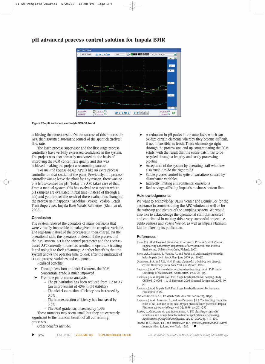
The haphazard adjustment of spent electrolyte flow ratehas been reduced. In the past, process controllers used tochange the pH setpoint every 20 minutes, provided that theywere present in the control room. Now, the pH setpoint ischanged automatically, every 10 minutes, by the APC. Figure 12 shows an impressive trend of the pH in autoclaveAC2110D. The green line represents the pH in the firstcompartment and the red line is the pH setpoint. The yellowline represents the pH in the fourth compartment. The blueline displays the changes made on the spent electrolyte flowrate.
Change managementThe manner in which the project was implemented enhancedpersonnel confidence in the control system. A controlengineer spent time on site, not only to gain anunderstanding of the process but also to explain the newcontrol system to those who were directly involved. Anyquestions or uncertainty experienced by the operators werequickly resolved.
Before the controller was implemented, a setpoint for thespent electrolyte flow was suggested to the process controller.The process controller then manually adjusted the spentelectrolyte flow. In this manner the process controller couldassess the performance of the APC and also indicate it was
pH advanced process control solution for Impala BMRJournal
Paper
The Journal of The Southern African Institute of Mining and Metallurgy VOLUME 109 NON-REFEREED PAPER JUNE 2009 373 ▲
Table II
Extraction efficiencies for Ni and Fe incorresponding periods in 2005 and 2006
Extraction 2005 2006efficiency Average Std deviation Average Std deviation
Ni 91.2% 1.70 91.7% 1.35Fe 85.2% 5.69 88.5% 6.97
Figure 11—Daily controller performance report
51-60:Template Journal 6/25/09 12:08 PM Page 373
pH advanced process control solution for Impala BMR
achieving the correct result. On the success of this process theAPC then assumed automatic control of the spent electrolyteflow rate.
The leach process supervisor and the first stage processcontrollers have verbally expressed confidence in the system.The project was also primarily motivated on the basis ofimproving the PGM concentrate quality and this wasachieved, making the project a resounding success.
‘For me, the CSense-based APC is like an extra processcontroller on that section of the plant. Previously, if a processcontroller was to leave the plant for any reason, there was noone left to control the pH. Today the APC takes care of that.From a manual system, this has evolved to a system wherepH samples are evaluated in real time (instead of through alab) and you can see the result of these evaluations changingthe process as it happens.’ Arnoldus (Vossie) Vosloo, LeachPlant Supervisor, Impala Base Metals Refineries (Khan, et al.2008).
ConclusionThe system relieved the operators of many decisions thatwere virtually impossible to make given the complex, variableand real-time nature of the processes in their charge. On theoperational side, the operators understand the process andthe APC system. pH is the control parameter and the CSense-based APC currently in use has resulted in operators trustingit and using it to their advantage. Another benefit is that thesystem allows the operator time to look after the multitude ofcritical process variables and equipment.
Realized benefits:➤ Through less iron and nickel content, the PGM
concentrate grade is much improved➤ From the performance analysis:
– The pH variation has been reduced from 1.2 to 0.7(an improvement of 40% in pH stability)
– The nickel extraction efficiency has increased by0.5%
– The iron extraction efficiency has increased by3.3%
– The PGM grade has increased by 1.4%These numbers may seem small, but they are extremely
significant to the financial benefit of all our refiningprocesses.
Other benefits include:
➤ A reduction in pH peaks in the autoclave, which canoxidize certain elements whereby they become difficult,if not impossible, to leach. These elements go rightthrough the process and end up contaminating the PGMsolids, with the result that the entire batch has to berecycled through a lengthy and costly processingpipeline
➤ Acceptance of the system by operating staff who nowalso trust it to do the right thing
➤ Stable process control in spite of variations caused bydisturbance variables
➤ Indirectly limiting environmental emissions➤ Real savings affecting Impala’s business bottom line.
AcknowledgementsWe want to acknowledge Dauw Venter and Dennis Lee for theassistance in commissioning the APC solution as well as forthe write-up and picture of the sampling system. We wouldalso like to acknowledge the operational staff that assistedand contributed in making this a very successful project, i.e.Selilo Semosa and Vossie Vosloo, as well as Impala PlatinumLtd for allowing its publication.
ReferencesJUUSO, E.K. Modelling and Simulation in Advanced Process Control, Control
Engineering Laboratory, Department of Environmental and ProcessEngineering, University of Oulu, Finland. 2007.
KHAN, A.F., SPANDIEL, T., VOSLOO, A., and SEMOSA, S. Advanced pH controllerhelps Impala BMR. MMS Mag, June 2008, pp. 20–22.
OGUNNAIKE, B.A. and RAY, W.H. Process Dynamics, Modeling and Control.Oxford University Press, New York and Oxford. 1994.
RADEMAN, J.A.M. The simulation of a transient leaching circuit. PhD thesis,University of Stellenbosch, South Africa. 1995. 261 pp.
RADEMAN, J.A.M. Impala BMR First Stage Leach pH control, Scoping StudyCSKM0510-0263-1.1, 15 December 2005 (Internal document), 2005. 49pp.
RADEMAN, J.A.M. Impala BMR First Stage Leach pH control, PerformanceEvaluation. 2007.
CSKM0510-0263-3.3, 12 March 2007 (Internal document), 10 pp.RADEMAN, J.A.M., LORENZEN, L., and VAN DEVENTER, J.S.J. The leaching character-
istics of Ni-Cu matte in the acid-oxygen pressure leach process at ImpalaPlatinum. Hydrometallurgy, vol. 52, 1999. pp. 231–252.
REZNIK, L., GHANAYEM, O., and BOURMISTROV, A. PID plus fuzzy controllerstructures as a design base for industrial applications. EngineeringApplications of Artificial Intelligence, vol. 13, 2000. pp. 419–430.
SEBORG, D.E., EDGAR, T.F., and MELLICHAMP, D.A. Process Dynamics and Control.Johnson Wiley & Sons, New York. 1989. ◆
▲
374 JUNE 2009 VOLUME 109 NON-REFEREED PAPER The Journal of The Southern African Institute of Mining and Metallurgy
Figure 12—pH and spent electrolyte SCADA trend
51-60:Template Journal 6/25/09 12:08 PM Page 374