Embed Size (px)
Citation preview
POWR-GARD®
Supplemental Monitoring PGM-8325 SERIES Neutral Grounding Monitor
PGM-8325 MANUAL
NEUTRAL GROUNDING MONITOR
JULY 2, 2009
REVISION 10
F 1
CT1 CT2 A B L1 L2
GROUND
FAULT
RESET RESISTOR
FAULT
SW GI RI R G
POWER
RES TRIP
LEVEL (VAC)
200
1000
400
2000
20
100
GF TRIP
TIME (s)
1.0
0.1 2.0
100K
20K
RESMODE
SH
UV
GF
4.0 A
0.5 A
2.0 A
POWR-GARDNEUTRAL GROUNDING
MONITOR PGM-8325 SERIES
F 1
Copyright 2009 by Littelfuse, Inc.
All rights reserved. Publication: PGM-8325-SM Document: P95-C325-000SM Printed in Canada.
Rev. 10 Page i
PGM-8325 Neutral Grounding Monitor
TABLE OF CONTENTS Page Table of Contents.........................................................................................................i List of Figures..............................................................................................................ii List of Tables ...............................................................................................................ii 1. GENERAL ........................................................................................................ 1 1.1 Modern Resistance-Grounded Systems ......................................................... 1 1.2 PGM-8325 NGR Monitoring............................................................................. 2 2. OPERATION .................................................................................................... 2 2.1 Settings ............................................................................................................. 2 2.1.1 GF Trip Time......................................................................................... 2 2.1.2 GF.......................................................................................................... 2 2.1.3 Mode...................................................................................................... 2 2.1.4 RES ....................................................................................................... 3 2.1.5 RES Trip Level...................................................................................... 3 2.2 Indication and Reset ......................................................................................... 3 2.3 Fusing ............................................................................................................... 3 3. INSTALLATION ............................................................................................... 4 3.1 PGM-8325......................................................................................................... 4 3.2 Ground-Fault CT............................................................................................... 5 3.3 Sensing Resistor............................................................................................... 5 3.4 Isolated-Ground Connection ............................................................................ 7 3.5 Overhead Lines................................................................................................. 7 3.6 Remote Operation .......................................................................................... 12 3.7 Ground-Fault Testing...................................................................................... 12 4. TECHNICAL SPECIFICATIONS................................................................... 13 4.1 PGM-8325....................................................................................................... 13 4.2 Sensing Resistors........................................................................................... 15 4.3 Current Transformer ....................................................................................... 15 5. ORDERING INFORMATION ......................................................................... 16 7. TEST PROCEDURES.................................................................................... 17 7.1 Ground-Fault Performance Test .................................................................... 17 7.2 Resistor-Fault Tests........................................................................................ 18 7.2.1 Open Test ............................................................................................. 18 7.2.2 Voltage Test.......................................................................................... 19 7.3 Sensing-Resistor Test .................................................................................... 19
Rev. 10 Page ii
PGM-8325 Neutral Grounding Monitor
LIST OF FIGURES Page 1 Typical Application.............................................................................................4 2 PGM-8325 Outline and Mounting Details.........................................................5 3 Current Transformers........................................................................................6 4 PGE-600V Sensing Resistor ............................................................................7 5 PGE-05KV Sensing Resistor ............................................................................8 6 PGE-15KV Sensing Resistor ............................................................................9 7 PGE-25KV Sensing Resistor ..........................................................................10 8 PGB-0302 Remote Indication and Reset .......................................................11 9 PGB-0325 Remote Indication and Reset Assembly......................................11 10 Ground-Fault-Test Circuit................................................................................17
LIST OF TABLES Page 1 Settings For Typical Systems ...........................................................................3 2 Ground-Fault-Test Record ..............................................................................18
DISCLAIMER
Specifications are subject to change without notice. Littelfuse, Inc. is not liable for contingent or consequential damages, or for expenses sustained as a result of incorrect application, incorrect adjustment, or a malfunction.

Rev. 10 Page iii
PGM-8325 Neutral Grounding Monitor
This page intentionally left blank
Rev. 10 Page 1
PGM-8325 Neutral Grounding Monitor
1. GENERAL
1.1 Modern Resistance-Grounded Systems A high-resistance-grounded system uses a neutral-grounding resistor (NGR) with a low let-through current to limit ground-fault current. High-resistance grounding is gaining popularity because a ground-fault flash hazard exists in low-resistance- or solidly grounded systems and a ground fault can result in substantial point-of-fault damage. High-resistance grounding eliminates these problems and modern ground-fault protection operates reliably at these levels. Furthermore, the probability of an arc-flash incident is significantly reduced in a high-resistance-grounded system. NGR selection depends on system charging current and whether the system is an alarm-only or a tripping system. Alarm-only systems are usually restricted to system voltages up to 5 kV with NGR let-through currents of 5 A or less. Occasionally, alarm-only systems up to 15 kV and up to 10 A are used; however, they are not common because a ground fault on such a system tends to escalate to a phase-to-phase fault before the ground fault can be located and cleared. System charging current is the capacitive current that flows to ground when a bolted ground fault occurs. This current can be calculated or measured. For small systems, the magnitude of charging current is typically ½ A per 1,000 kVA on low-voltage systems and 1 A per 1,000 kVA on medium-voltage systems. In an alarm-only system or in a tripping system without selective coordination, choose an NGR with a let-through current larger than the system charging current and set the pick-up current of ground-fault devices at or below 50% of the NGR let-through current. In a tripping system with selective coordination, use ground-fault devices with a definite-time characteristic to achieve time coordination. Use the same pick-up current for all ground-fault devices—this value must be larger than the charging current of the largest feeder. Select an NGR with a let-through current between five and ten times the pick-up current of the ground-fault devices. Do not use a grounding transformer with a low-voltage resistor:
! The combined cost of a transformer and a low-voltage resistor is more than the
cost of a resistor rated for line-to-neutral voltage.
! A transformer saturated by a ground fault through a rectifier can make ground-
fault protection inoperative.
! Transformer inrush current up to twelve times rated current can cause a
ground-fault voltage larger than expected.
! A parallel transformer winding makes it difficult to monitor NGR continuity.
! A transformer can provide the inductance necessary to cause ferroresonance if
the NGR opens.
Following these guidelines will reduce the flash hazard, reduce point-of-fault
damage, achieve reliable ground-fault protection, and ensure a stable system not
subject to ferroresonance.
Rev. 10 Page 2
PGM-8325 Neutral Grounding Monitor
1.2 PGM-8325 NGR Monitoring The PGM-8325 is a neutral-grounding-resistor monitor for resistance-grounded systems up to 25 kVac. It measures current in a transformer or generator neutral, neutral-to-ground voltage, and continuity of the neutral-grounding resistor. The PGM-8325 coordinates these three measurements to detect a failed NGR or a ground fault and provides one output contact for shunt or undervoltage operation in a main-breaker trip circuit. Trips are latched and indicated by LED’s. Ground-fault current is sensed by a PGC-2056 window-type current transformer. Either CT input can be grounded to meet electrical codes. A trip level of 0.5, 2.0, or 4.0 A is switch selectable for use with a 5-, 15-, or 25-A grounding resistor. Trip time is adjustable from 0.1 to 2.0 seconds. Neutral-to-ground voltage and continuity of the neutral-grounding resistor are continuously measured through an PGE-series external sensing resistor connected to the neutral. A resistor fault will be detected if ground-fault current is not detected and neutral-to-ground voltage exceeds the trip-level setting, or if NGR resistance exceeds the trip resistance. A resistor-fault hold-off circuit prevents nuisance trips in alarm-only systems. For additional information on neutral-grounding-resistor monitoring, see “Monitoring Neutral-Grounding Resistors” at www.littelfuse.com.
2. OPERATION
2.1 Settings 2.1.1 GF Trip Time Ground-fault trip time is adjustable from 0.1 to 2.0 seconds. Time-coordinated ground-fault protection requires this setting to be longer than the trip times of downstream ground-fault devices.
2.1.2 GF The ground-fault-circuit trip level is 0.5, 2.0, or 4.0 A when current is sensed with
a PGC-2056 current transformer. Since the ground-fault-circuit trip level should not
be greater than 20% of the grounding resistor let-through current, these levels are
appropriate for use with 5-, 15-, or 25-A grounding resistors. See Table 1. For
other applications, the trip level of the ground-fault circuit is 0.25, 1.0, or 2.0% of the
primary rating of the 5-A-secondary current transformer.
2.1.3 Mode In the shunt-trip mode (SH), the output relay energizes and its contact closes if a resistor-fault or ground-fault trip occurs. The shunt-trip mode is not fail-safe because shunt-trip devices do not operate if supply voltage fails.
In the undervoltage mode (UV), the output relay energizes and its contact closes if
the resistor-fault and ground-fault circuits are not tripped. The undervoltage mode is
referred to as fail-safe because undervoltage devices release if supply voltage fails.
Rev. 10 Page 3
PGM-8325 Neutral Grounding Monitor
2.1.4 RES This switch setting must correspond to the resistance of the external sensing resistor.
For the PGE-600V and PGE-05KV, select 20K. For the PGE-15KV and PGE-25KV,
select 100K.
2.1.5 RES Trip Level Neutral-to-ground trip voltage is adjustable from 20 to 400 Vac with a 20-k"
sensing resistor, and 100 to 2,000 Vac with a 100-k" sensing resistor. To prevent
false resistor-fault trips, the RES TRIP LEVEL should be set higher than the voltage
across the neutral-grounding resistor when neutral-to-ground current is equal to the
operating value of the ground-fault circuit. Typical values for 5-, 15-, and 25-A
tripping systems are shown in Table 1. For other systems, refer to the NGR Monitor
Set-Point Assistant at www.littelfuse.com.
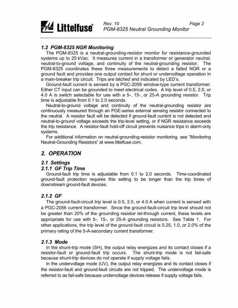
TABLE 1. Settings for Typical Systems
System
Voltage
Neutral-Grounding
Resistor
Sensing
Resistor
Ground-Fault
Trip Level
Res
Trip Level
(Volts)
Let Through (Amperes)
Resistance (Ohms)
Model Resistance (Ohms)
(Amperes)
(Volts)
480
600
2,400
4,160
480
600
2,400
4,160
7,200
14,400
7,200
14,400
25,000
5
5
5
5
15
15
15
15
15
15
25
25
25
55
69
277
480
18
23
92
160
277
554
166
332
577
PGE-600V
PGE-600V
PGE-05KV
PGE-05KV
PGE-600V
PGE-600V
PGE-05KV
PGE-05KV
PGE-15KV
PGE-15KV
PGE-15KV
PGE-15KV
PGE-25KV
20,000
20,000
20,000
20,000
20,000
20,000
20,000
20,000
100,000
100,000
100,000
100,000
100,000
0.5
0.5
0.5
0.5
2.0
2.0
2.0
2.0
2.0
2.0
4.0
4.0
4.0
30
40
140
240
40
50
190
320
600
1,100
700
1,400
2,000
2.2 Indication and Reset The green POWER LED indicates that the internal power supply is on. Red LED's indicate ground-fault and resistor-fault trips. When a trip occurs, the PGM-8325 remains latched until the reset switch is pressed or supply voltage is cycled. Terminals are provided for remote indication and reset as shown in Fig. 1.
2.3 Fusing The output contact is protected by fuse F1 (4.0 A, time delay).
Rev. 10 Page 4
PGM-8325 Neutral Grounding Monitor
3. INSTALLATION
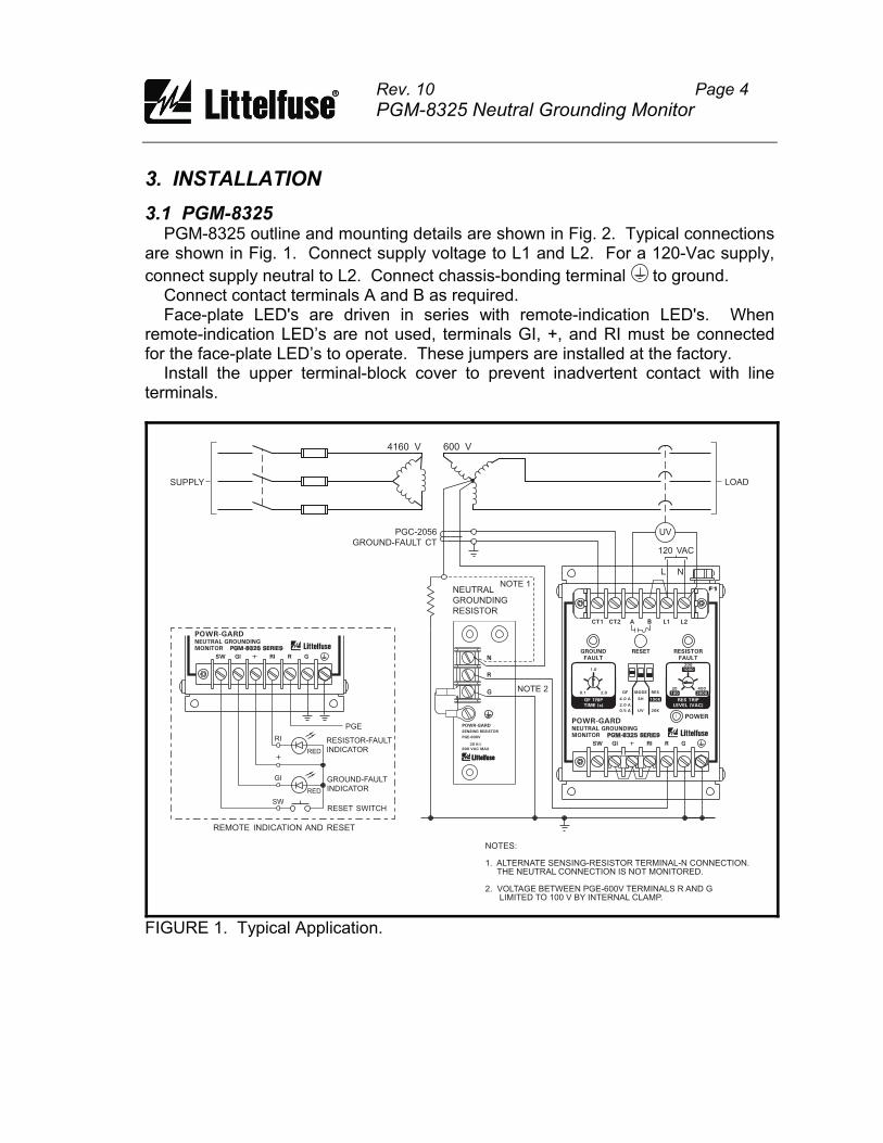
3.1 PGM-8325 PGM-8325 outline and mounting details are shown in Fig. 2. Typical connections are shown in Fig. 1. Connect supply voltage to L1 and L2. For a 120-Vac supply,
connect supply neutral to L2. Connect chassis-bonding terminal to ground. Connect contact terminals A and B as required. Face-plate LED's are driven in series with remote-indication LED's. When remote-indication LED’s are not used, terminals GI, +, and RI must be connected for the face-plate LED’s to operate. These jumpers are installed at the factory. Install the upper terminal-block cover to prevent inadvertent contact with line terminals.
600 V4160 V
SUPPLY
NEUTRAL
GROUNDING
RESISTOR
PGC-2056
GROUND-FAULT CT
UV
120 VAC
L N
LOAD
RESISTOR-FAULT
INDICATOR
GROUND-FAULT
INDICATOR
RESET SWITCH
REMOTE INDICATION AND RESET
RED
RED
PGE
RI
GI
SW
NOTES:
1. ALTERNATE SENSING-RESISTOR TERMINAL-N CONNECTION.THE NEUTRAL CONNECTION IS NOT MONITORED.
2. VOLTAGE BETWEEN PGE-600V TERMINALS R AND GLIMITED TO 100 V BY INTERNAL CLAMP.
NOTE 1
NOTE 2
F 1
CT1 CT2 A B L1 L2
GROUND
FAULT
RESET RESISTOR
FAULT
POWER
RES TRIP
LEVEL (VAC)
200
1000
400
2000
20
100
GF TRIP
TIME (s)
1.0
0.1 2.0
100K
20K
RESMODE
SH
UV
GF
4.0 A
0.5 A
2.0 A
SW GI RI R G
POWR-GARDNEUTRAL GROUNDING
MONITOR PGM-8325 SERIES
F 1
POWR-GARD
PGE-600V
SENSING RESISTOR
20 K
600 VAC MAX
W
N
R
G
SW GI RI R G
POWR-GARDNEUTRAL GROUNDING
MONITOR PGM-8325 SERIES
FIGURE 1. Typical Application.
, and RI are provided for remote LED indication and remote
e driven in series with the front-panel LED’s.
Remove factory-installed jumpers from terminals GI, +, and RI, and connect a
remote kit as shown in Fig. 1. Optional remote kits are shown in Figs. 8 and 9.
For general-purpose applications, use the PGB-0325 Remote Indication and Reset
Assembly. Connect terminals SW, GI, +, and RI to remote-kit terminals SW, GI, +, and
For 22-mm-component PGB-0302 applications, connect terminal X2 of the red ground-fault indicator to GI, terminal X2 of the red resistor-fault indicator to RI, and
r remote reset, connect the normally open
Use CT-primary current injection to test the ground-fault circuit. Fig. 10 shows a t Relay Test Unit. The PGT-0400 has a
of this manual. Record the test results irements of the National Electrical Code
data can be made available to the authority
Rev. 10 Page 5
PGM-8325 Neutral Grounding Monitor
NOTES:
1.
2.
3.
4.
5.
DIMENSIONS IN MILLIMETRES (INCHES).
TERMINAL-BLOCK SCREWS: 6-32 x 0.25.
MOUNTING SCREWS: M4 OR 8-32.
SHOWN WITH TERMINAL-BLOCK COVER REMOVED.
MINIMUM CLEARANCE FOR FUSE REMOVAL.
109.0
(4.29)
(3.50)
(5.5
0)
(5.9
0)
88.9
139.7
150.0
4 .8 (0 . 19 ) D IA
100.0
(3.93)
(3.06)
77.8
43.5
(1.7
1)
NOTE 5
NOTE 4
F 1
CT1 CT2 A B L1 L2
GROUND
FAULT
RESET RESISTOR
FAULT
SW GI RI R G
POWER
RES TRIP
LEVEL (VAC)
200
1000
400
2000
20
100
GF TRIP
TIME (s)
1.0
0.1 2.0
100K
20K
RESMODE
SH
UV
GF
4.0 A
0.5 A
2.0 A
POWR-GARDNEUTRAL GROUNDING
MONITOR PGM-8325 SERIES
F 1
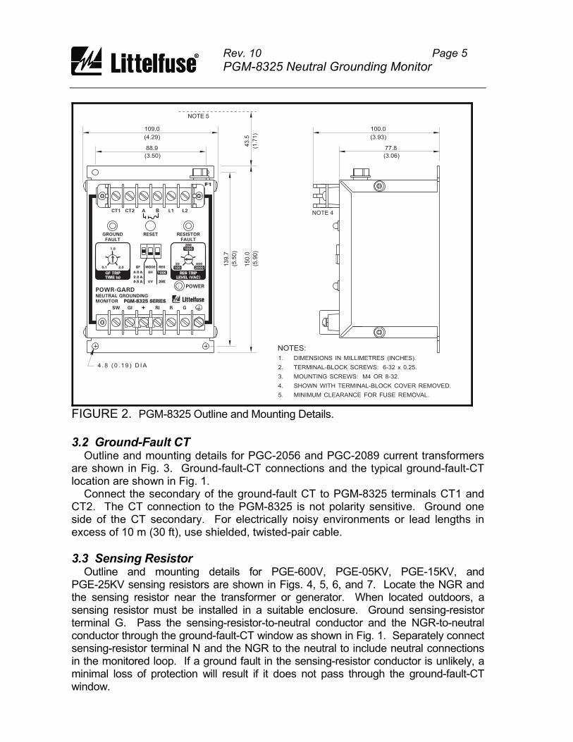
FIGURE 2. PGM-8325 Outline and Mounting Details.
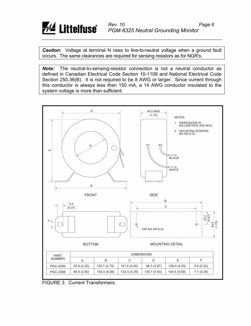
3.2 Ground-Fault CT Outline and mounting details for PGC-2056 and PGC-2089 current transformers are shown in Fig. 3. Ground-fault-CT connections and the typical ground-fault-CT location are shown in Fig. 1. Connect the secondary of the ground-fault CT to PGM-8325 terminals CT1 and CT2. The CT connection to the PGM-8325 is not polarity sensitive. Ground one side of the CT secondary. For electrically noisy environments or lead lengths in excess of 10 m (30 ft), use shielded, twisted-pair cable.
3.3 Sensing Resistor Outline and mounting details for PGE-600V, PGE-05KV, PGE-15KV, and PGE-25KV sensing resistors are shown in Figs. 4, 5, 6, and 7. Locate the NGR and the sensing resistor near the transformer or generator. When located outdoors, a sensing resistor must be installed in a suitable enclosure. Ground sensing-resistor terminal G. Pass the sensing-resistor-to-neutral conductor and the NGR-to-neutral conductor through the ground-fault-CT window as shown in Fig. 1. Separately connect sensing-resistor terminal N and the NGR to the neutral to include neutral connections in the monitored loop. If a ground fault in the sensing-resistor conductor is unlikely, a minimal loss of protection will result if it does not pass through the ground-fault-CT window.
Rev. 10 Page 6
PGM-8325 Neutral Grounding Monitor
Caution: Voltage at terminal N rises to line-to-neutral voltage when a ground fault occurs. The same clearances are required for sensing resistors as for NGR's.
Note: The neutral-to-sensing-resistor connection is not a neutral conductor as defined in Canadian Electrical Code Section 10-1108 and National Electrical Code Section 250.36(B). It is not required to be 8 AWG or larger. Since current through this conductor is always less than 150 mA, a 14 AWG conductor insulated to the system voltage is more than sufficient.
D
A
E
B
FRONT
9.4
(0.37)
F
BOTTOM
B
C
TAP M4 OR 8-32
22.2
(0.8
7)
44.5
(1.7
5)
MOUNTING DETAIL
SIDE
WHITE
BLACK
X1 X2
44.5 MAX
(1.75)NOTES:
1. DIMENSIONS INMILLIMETRES (INCHES).
2. MOUNTING SCREWS:M4 OR 8-32.
PARTNUMBER
PGC-2056
PGC-2089
A B C D E F
55.9 (2.20)
88.9 (3.50)
120.7 (4.75)
154.0 (6.06)
101.6 (4.00)
133.4 (5.25)
98.3 (3.87)
139.7 (5.50)
108.0 (4.25)
144.5 (5.69)
5.6 (0.22)
7.1 (0.28)
DIMENSIONS
FIGURE 3. Current Transformers.
Rev. 10 Page 7
PGM-8325 Neutral Grounding Monitor
MOUNTING DETAIL
10
5.0
8.0
89
.08
.0
40.0
19.0 10.510.5
(4.1
3)
(0.3
1)
(3.5
0)
(0.3
1)
(1.57)
(0.75) (0.41)(0.41)
NOTE 3
SIDE
41.5
22.2
(1.63)
(0.87)
FRONT
NOTES:
1.
2.
3.
4.
DIMENSIONS IN MILLIMETRES (INCHES).
TERMINAL-BLOCK SCREWS: 6-32 x 0.25.
MOUNTING SCREWS: M4 OR 8-32.
ENCLOSURE IS ELECTRICALLY CONNECTED TO TERMINAL GTHROUGH JUMPER FROM TERMINAL G TO SCREW.THIS CONNECTION MAY BE REMOVED FOR DIELECTRIC STRENGTHTESTING. ENSURE THAT THE JUMPER IS INSTALLED AFTER TESTING.
4.5 (0.18) DIA
C'BORE 10.0 (0.39) DIA
3.2 (0.13) DEEP
40.0
10
5.0
(1.57)
(4.1
3)
RATINGS:MAXIMUM VOLTAGE . 600 VacMAXIMUM CURRENT . 30 mA
RESISTANCE . . . . . . . 20 kTHERMAL:
420 Vac . . . . . . . . . . CONTINUOUS600 Vac . . . . . . . . . . 6 MINUTES ON,
60 MINUTES OFF
W
POWR-GARD
PGE-600V
SENSING RESISTOR
20 K
600 VAC MAX
W
N
R
G
FIGURE 4. PGE-600V Sensing Resistor.
3.4 Isolated-Ground Connection The PGM-8325 is intended for use in installations where the NGR is connected to local ground. Some installations require the NGR to be isolated from local ground. See Technical Information 3.1 “NGR Monitoring with Isolated Ground Beds” at www.littelfuse.com.
3.5 Overhead Lines In overhead-line applications, atmospheric conditions can cause false resistor-fault
trips. A PGR-5330 NGR Monitor is recommended for these applications.
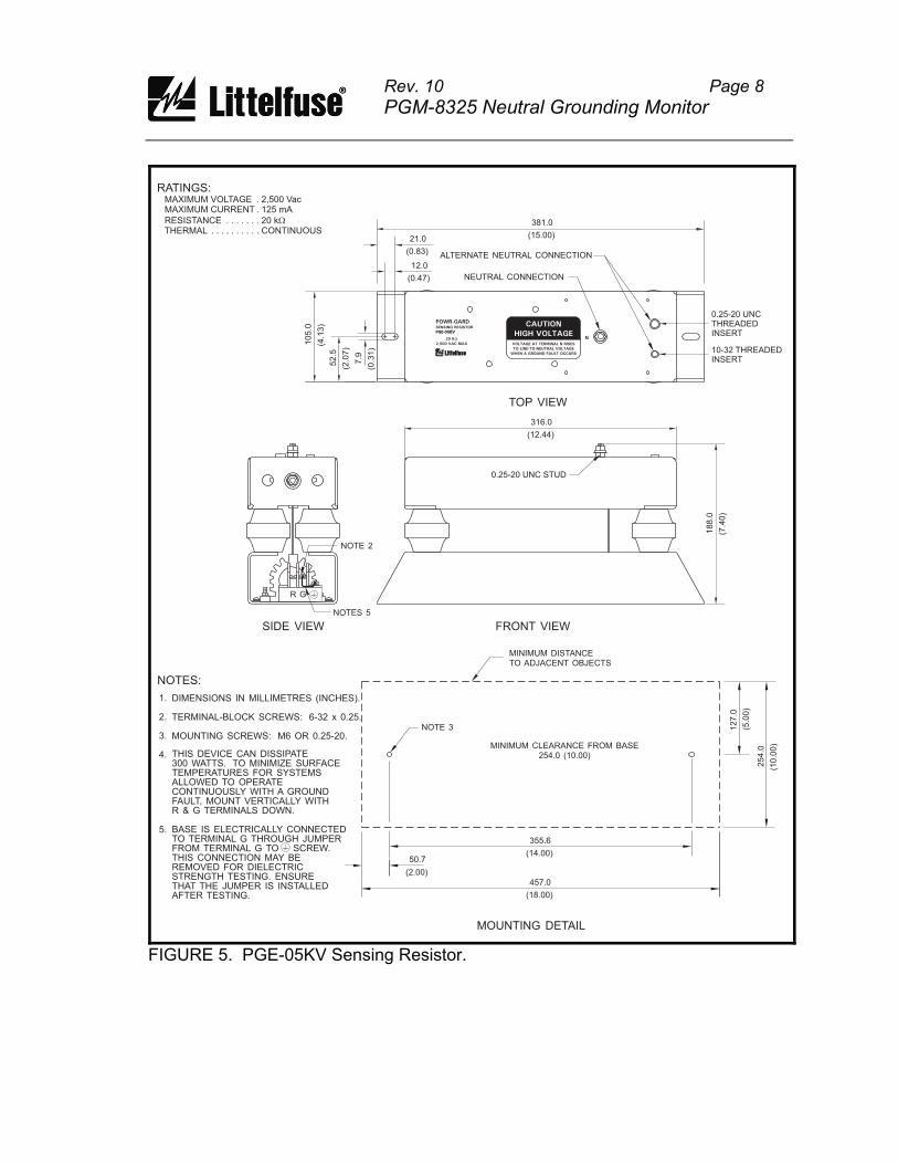
Rev. 10 Page 8
PGM-8325 Neutral Grounding Monitor
355.6
254.0
127.0
457.0
50.7(14.00)
(10.0
0)
(5.0
0)
(18.00)
(2.00)
MINIMUM DISTANCETO ADJACENT OBJECTS
MOUNTING DETAIL
NOTE 3
NOTES:
1.
2.
3.
4.
DIMENSIONS IN MILLIMETRES (INCHES).
TERMINAL-BLOCK SCREWS: 6-32 x 0.25.
MOUNTING SCREWS: M6 OR 0.25-20.
THIS DEVICE CAN DISSIPATE300 WATTS. TO MINIMIZE SURFACETEMPERATURES FOR SYSTEMSALLOWED TO OPERATECONTINUOUSLY WITH A GROUNDFAULT, MOUNT VERTICALLY WITHR & G TERMINALS DOWN.
BASE IS ELECTRICALLY CONNECTEDTO TERMINAL G THROUGH JUMPERFROM TERMINAL G TO SCREW.THIS CONNECTION MAY BEREMOVED FOR DIELECTRICSTRENGTH TESTING. ENSURETHAT THE JUMPER IS INSTALLEDAFTER TESTING.
316.0
GR
188.0
(12.44)
(7.4
0)
FRONT VIEWSIDE VIEW
0.25-20 UNC STUD
381.0
21.0
12.0
105.0
7.9
52.5
(15.00)
(0.83)
(0.47)
(4.1
3)
(0.3
1)
(2.0
7)
NEUTRAL CONNECTION
ALTERNATE NEUTRAL CONNECTION
TOP VIEW
0.25-20 UNCTHREADEDINSERT
10-32 THREADEDINSERT
RATINGS:MAXIMUM VOLTAGE . 2,500 VacMAXIMUM CURRENT . 125 mA
RESISTANCE . . . . . . . 20 kTHERMAL . . . . . . . . . . CONTINUOUS
W
5.
MINIMUM CLEARANCE FROM BASE254.0 (10.00)
NOTES 5
NOTE 2
CAUTION
HIGH VOLTAGE
VOLTAGE AT TERMINAL N RISES
TO LINE-TO-NEUTRAL VOLTAGE
WHEN A GROUND FAULT OCCURS
N
POWR-GARDSENSING RESISTOR
PGE-05KV
20 K
2,500 VAC MAX
W
FIGURE 5. PGE-05KV Sensing Resistor.
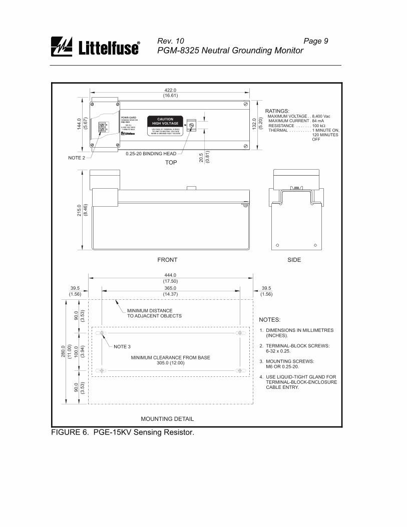
Rev. 10 Page 9
PGM-8325 Neutral Grounding Monitor
N
C A U T I O N
H I G H V O L T A G E
422.0(16.61)
14
4.0
21
5.0
90
.0
28
0.0
10
0.0
90
.0
(5.6
7)
(8.4
6)
(3.5
3)
(11
.00
)
(3.9
4)
(3.5
3)
FRONT
MOUNTING DETAIL
SIDE
NOTES:
TOP
444.0
(17.50)
(14.37)(1.56) (1.56)
365.039.5 39.5
MINIMUM DISTANCETO ADJACENT OBJECTS
NOTE 3
1. DIMENSIONS IN MILLIMETRES(INCHES).
2. TERMINAL-BLOCK SCREWS:6-32 x 0.25.
3. MOUNTING SCREWS:M6 OR 0.25-20.
4. USE LIQUID-TIGHT GLAND FORTERMINAL-BLOCK-ENCLOSURECABLE ENTRY.
13
2.0
(5.2
0)
RATINGS:MAXIMUM VOLTAGE. . 8,400 VacMAXIMUM CURRENT . 84 mA
RESISTANCE . . . . . . . 100 kTHERMAL . . . . . . . . . . 1 MINUTE ON,
120 MINUTESOFF
W
MINIMUM CLEARANCE FROM BASE305.0 (12.00)
0.25-20 BINDING HEAD
20
.5
(0.8
1)
NOTE 2
NR
G
POWR-GARDSENSING RESISTOR
PGE-15KV
100 K
8,400 VAC MAX
1 MINUTE MAX
W
CAUTION
HIGH VOLTAGE
VOLTAGE AT TERMINAL N RISES
TO LINE-TO-NEUTRAL VOLTAGE
WHEN A GROUND FAULT OCCURS
FIGURE 6. PGE-15KV Sensing Resistor.
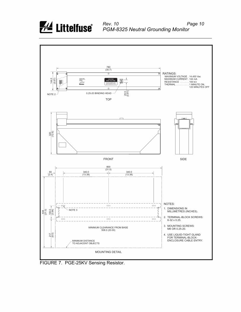
Rev. 10 Page 10
PGM-8325 Neutral Grounding Monitor
800
60 340.0340.0
534
217
100.0
(31.5)
(2.4) (13.38)(13.38)
(21.0
)
(8.5
)(3
.94)
MOUNTING DETAIL
NOTES:
1. DIMENSIONS INMILLIMETRES (INCHES).
2. TERMINAL-BLOCK SCREWS:6-32 x 0.25.
3. MOUNTING SCREWS:M6 OR 0.25-20.
4. USE LIQUID-TIGHT GLANDFOR TERMINAL-BLOCK-ENCLOSURE CABLE ENTRY.
NOTE 3
MINIMUM DISTANCETO ADJACENT OBJECTS
320
(12.6
)
FRONT SIDE
780
(5.6
7)
20.5
(30.7)
(0.8
1)
TOP
RATINGS:MAXIMUM VOLTAGE . 14,400 VacMAXIMUM CURRENT . 144 mA
RESISTANCE . . . . . . . 100 kTHERMAL . . . . . . . . . . 1 MINUTE ON,
120 MINUTES OFF
W
0.25-20 BINDING HEAD
144.0
MINIMUM CLEARANCE FROM BASE508.0 (20.00)
NOTE 2
NR
G
POWR-GARDSENSING RESISTOR
PGE-25KV
100 K
14,400 VAC MAX
1 MINUTE MAX
W
CAUTION
HIGH VOLTAGE
VOLTAGE AT TERMINAL N RISES
TO LINE-TO-NEUTRAL VOLTAGE
WHEN A GROUND FAULT OCCURS
FIGURE 7. PGE-25KV Sensing Resistor.
Voltage at terminal N rises to line-to-neutral voltage when a ground fault
The neutral-to-sensing-resistor connection is not a neutral conductor as defined in Canadian Electrical Code Section 10-1108 and National Electrical Code
be 8 AWG or larger. Since current through , a 14 AWG conductor insulated to the
Rev. 10 Page 11
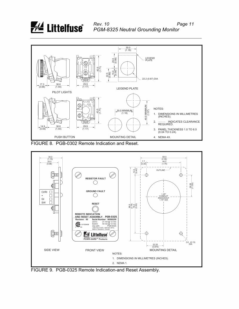
PGM-8325 Neutral Grounding Monitor
NOTES:
1. DIMENSIONS IN MILLIMETRES(INCHES).
2. INDICATES CLEARANCEREQUIRED.
3. PANEL THICKNESS 1.0 TO 6.0(0.04 TO 0.24).
4. NEMA 4X.
LEGEND PLATE
30.0(1.18)
LEGENDPLATE
22.2 (0.87) DIA
25.0
(0.9
8)
15.0
(0.5
9)
22.5
(0.8
9)
MOUNTING DETAIL
30.0 MINIMUM(1.18)
40.0
MIN
IMU
M(1
.57)
PILOT LIGHTS
36.6(1.44)
17.3(0.68)
29.9(1.17)
43.5
(1.7
1)
PUSH BUTTON
36.6(1.44)
14.9(0.59)
29.9(1.17)
43.5
(1.7
1)
FIGURE 8. PGB-0302 Remote Indication and Reset.
FRONT VIEW
60.0(2.36)44.5
(1.75)(0.30)
(0.4
0)
7.7
10.0
96.0
(3.7
8)
76.0
(3.0
0)
(0.875)22.25
28.5
8(1
.125)
1.25"CONDUIT
KNOCKOUT1.70" DIA
3.8 (0.15)DIA
MOUNTING DETAILSIDE VIEW
30.0(1.18)
25.0(0.98)
CI/RI
+
GI
SW
OUTLINE
NOTES:
1. DIMENSIONS IN MILLIMETRES (INCHES).
2. NEMA 1.
RESISTOR FAULT
GROUND FAULT
RESET
REMOTE INDICATION
AND RESET ASSEMBLY PGB-0325
POWR-GARD ProductsTM
R
LR 53428
USC
R
Revision: Serial Number:00 90500250
1-800-TEC-FUSE (1-800-832-3873)Made in Saskatoon, Canada
LED’s:Switch:Use with:
21 mA @ 12 Vdc50 mA @ 12 Vdc
PGM-8325
FIGURE 9. PGB-0325 Remote Indication-and Reset Assembly.
Rev. 10 Page 12
PGM-8325 Neutral Grounding Monitor
3.6 Remote Operation Terminals SW, GI, +, and RI are provided for remote LED indication and remote
reset as shown in Fig. 1. Remote LED's are driven in series with the front-panel LED’s.
Remove factory-installed jumpers from terminals GI, +, and RI, and connect a
remote kit as shown in Fig. 1. Optional remote kits are shown in Figs. 8 and 9.
Standard LED indicator lamps are not compatible with the PGM-8325.
For general-purpose applications, use the PGB-0325 Remote Indication and Reset
Assembly. Connect terminals SW, GI, +, and RI to remote-kit terminals SW, GI, +, and
CI/RI. For 22-mm-component PGB-0302 applications, connect terminal X2 of the red ground-fault indicator to GI, terminal X2 of the red resistor-fault indicator to RI, and connect indicator X1 terminals to +. For remote reset, connect the normally open push-button switch across terminals + and SW.
3.7 Ground-Fault Testing
Use CT-primary current injection to test the ground-fault circuit. Fig. 10 shows a test circuit using the PGT-0400 Ground-Fault Relay Test Unit. The PGT-0400 has a programmable output of 0.5 to 9.9 A for a duration of 0.1 to 9.9 seconds. A test-record form is provided in Section 7 of this manual. Record the test results and test dates on this form to meet the requirements of the National Electrical Code (NEC). Retain the form so that the test data can be made available to the authority having jurisdiction.
Rev. 10 Page 13
PGM-8325 Neutral Grounding Monitor
4. TECHNICAL SPECIFICATIONS
4.1 PGM-8325
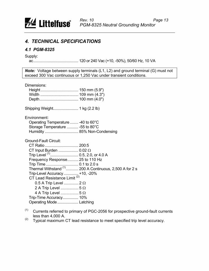
Supply: ac........................................... 120 or 240 Vac (+10, -50%), 50/60 Hz, 10 VA
Note: Voltage between supply terminals (L1, L2) and ground terminal (G) must not exceed 300 Vac continuous or 1,250 Vac under transient conditions.
Dimensions: Height .................................... 150 mm (5.9") Width .................................. 109 mm (4.3") Depth..................................... 100 mm (4.0") Shipping Weight........................ 1 kg (2.2 lb) Environment: Operating Temperature ........ -40 to 60°C Storage Temperature ........... -55 to 80°C Humidity ................................ 85% Non-Condensing Ground-Fault Circuit: CT Ratio ................................ 200:5
CT Input Burden ................... 0.02 Trip Level
(1)........................... 0.5, 2.0, or 4.0 A
Frequency Response.......... 25 to 110 Hz Trip Time ............................... 0.1 to 2.0 s Thermal Withstand
(1)............ 200 A Continuous, 2,500 A for 2 s
Trip-Level Accuracy.............. +10, -20% CT Lead Resistance Limit
(2)
0.5 A Trip Level ............. 2
2 A Trip Level ................ 5
4 A Trip Level ................ 5 Trip-Time Accuracy............... 10% Operating Mode.................... Latching (1)
Currents referred to primary of PGC-2056 for prospective ground-fault currents less than 4,000 A.
(2) Typical maximum CT lead resistance to meet specified trip level accuracy.
Rev. 10 Page 14
PGM-8325 Neutral Grounding Monitor
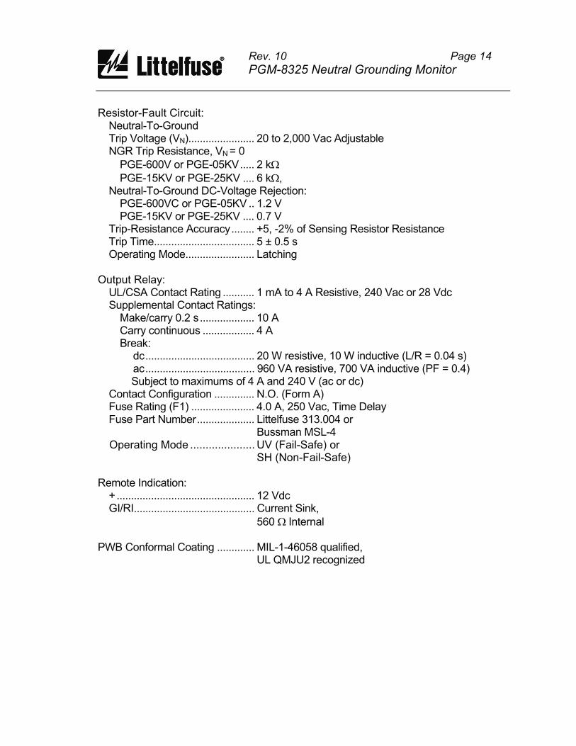
Resistor-Fault Circuit: Neutral-To-Ground Trip Voltage (VN)....................... 20 to 2,000 Vac Adjustable NGR Trip Resistance, VN = 0
PGE-600V or PGE-05KV..... 2 k
PGE-15KV or PGE-25KV .... 6 k , Neutral-To-Ground DC-Voltage Rejection: PGE-600VC or PGE-05KV .. 1.2 V PGE-15KV or PGE-25KV .... 0.7 V Trip-Resistance Accuracy........ +5, -2% of Sensing Resistor Resistance Trip Time................................... 5 ± 0.5 s Operating Mode........................ Latching Output Relay: UL/CSA Contact Rating ........... 1 mA to 4 A Resistive, 240 Vac or 28 Vdc Supplemental Contact Ratings: Make/carry 0.2 s................... 10 A Carry continuous .................. 4 A Break: dc...................................... 20 W resistive, 10 W inductive (L/R = 0.04 s) ac...................................... 960 VA resistive, 700 VA inductive (PF = 0.4) Subject to maximums of 4 A and 240 V (ac or dc) Contact Configuration .............. N.O. (Form A) Fuse Rating (F1) ...................... 4.0 A, 250 Vac, Time Delay Fuse Part Number.................... Littelfuse 313.004 or Bussman MSL-4 Operating Mode ..................... UV (Fail-Safe) or SH (Non-Fail-Safe) Remote Indication: + ................................................ 12 Vdc GI/RI.......................................... Current Sink,
560 Internal PWB Conformal Coating ............. MIL-1-46058 qualified, UL QMJU2 recognized
stor monitor for resistance-grounded in a transformer or generator neutral,
of the neutral-grounding resistor. The three measurements to detect a failed NGR or a
t for shunt or undervoltage operation in
Ground-fault current is sensed by a PGC-2056 window-type current transformer. al codes. A trip level of 0.5, 2.0, or
5-, 15-, or 25-A grounding resistor. Trip
Neutral-to-ground voltage and continuity of the neutral-grounding resistor are external sensing resistor connected to
ed if ground-fault current is not detected and setting, or if NGR resistance exceeds
circuit prevents nuisance trips in alarm-only
For additional information on neutral-grounding-resistor monitoring, see “Monitoring
0.1 to 2.0 seconds. Time-coordinated ground-fault protection requires this setting to be longer than the trip times of
rrent is sensed with
ound-fault-circuit trip level should not
stor let-through current, these levels are
appropriate for use with 5-, 15-, or 25-A grounding resistors. See Table 1. For
2.0% of the
relay energizes and its contact closes if a . The shunt-trip mode is not fail-safe
In the undervoltage mode (UV), the output relay energizes and its contact closes if
t circuits are not tripped. The undervoltage mode is
Rev. 10 Page 15
PGM-8325 Neutral Grounding Monitor
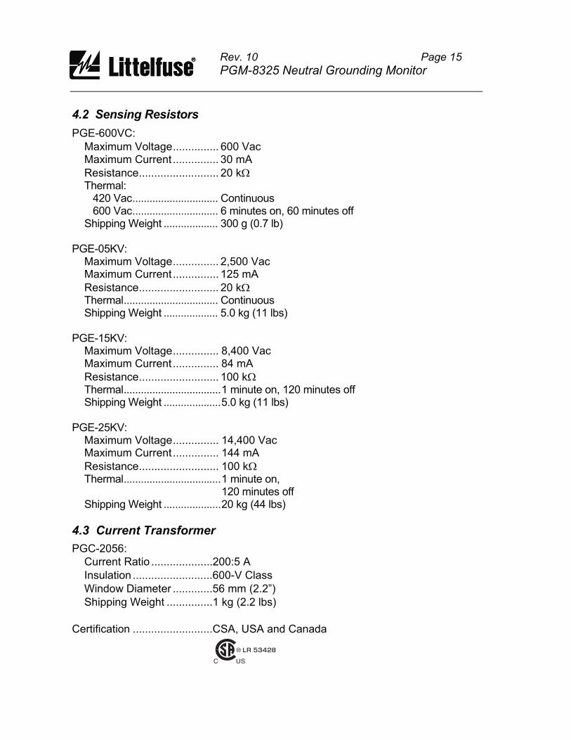
4.2 Sensing Resistors
PGE-600VC:
Maximum Voltage............... 600 Vac Maximum Current ............... 30 mA
Resistance.......................... 20 k Thermal: 420 Vac.............................. Continuous 600 Vac.............................. 6 minutes on, 60 minutes off Shipping Weight ................... 300 g (0.7 lb) PGE-05KV: Maximum Voltage............... 2,500 Vac Maximum Current ............... 125 mA
Resistance.......................... 20 k Thermal................................. Continuous Shipping Weight ................... 5.0 kg (11 lbs) PGE-15KV: Maximum Voltage............... 8,400 Vac Maximum Current ............... 84 mA
Resistance.......................... 100 k Thermal..................................1 minute on, 120 minutes off Shipping Weight ....................5.0 kg (11 lbs) PGE-25KV: Maximum Voltage............... 14,400 Vac Maximum Current ............... 144 mA
Resistance.......................... 100 k Thermal..................................1 minute on, 120 minutes off Shipping Weight ....................20 kg (44 lbs)
4.3 Current Transformer
PGC-2056:
Current Ratio ....................200:5 A
Insulation ..........................600-V Class
Window Diameter .............56 mm (2.2”)
Shipping Weight ...............1 kg (2.2 lbs)
Certification ..........................CSA, USA and Canada
LR 53428
USC
R
Rev. 10 Page 16
PGM-8325 Neutral Grounding Monitor
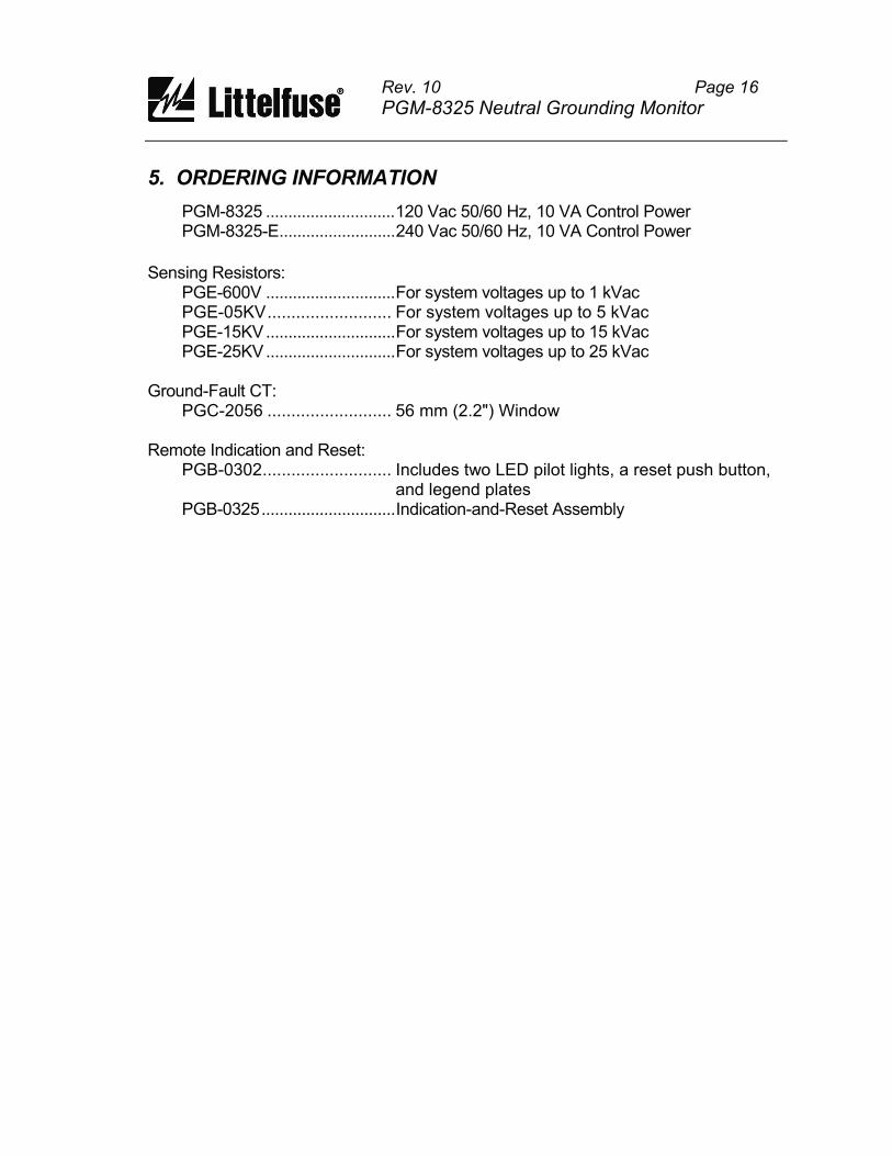
5. ORDERING INFORMATION
PGM-8325 .............................120 Vac 50/60 Hz, 10 VA Control Power PGM-8325-E..........................240 Vac 50/60 Hz, 10 VA Control Power
Sensing Resistors: PGE-600V .............................For system voltages up to 1 kVac PGE-05KV.......................... For system voltages up to 5 kVac PGE-15KV.............................For system voltages up to 15 kVac PGE-25KV.............................For system voltages up to 25 kVac Ground-Fault CT:
PGC-2056 .......................... 56 mm (2.2") Window Remote Indication and Reset: PGB-0302........................... Includes two LED pilot lights, a reset push button,
and legend plates PGB-0325..............................Indication-and-Reset Assembly
Rev. 10 Page 17
PGM-8325 Neutral Grounding Monitor
7. TEST PROCEDURES
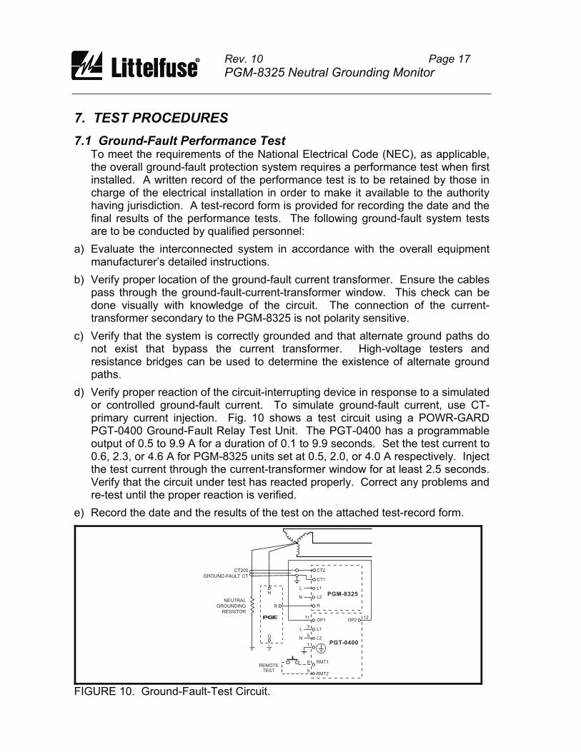
7.1 Ground-Fault Performance Test
To meet the requirements of the National Electrical Code (NEC), as applicable, the overall ground-fault protection system requires a performance test when first installed. A written record of the performance test is to be retained by those in charge of the electrical installation in order to make it available to the authority having jurisdiction. A test-record form is provided for recording the date and the final results of the performance tests. The following ground-fault system tests are to be conducted by qualified personnel:
a) Evaluate the interconnected system in accordance with the overall equipment manufacturer’s detailed instructions.
b) Verify proper location of the ground-fault current transformer. Ensure the cables pass through the ground-fault-current-transformer window. This check can be done visually with knowledge of the circuit. The connection of the current-transformer secondary to the PGM-8325 is not polarity sensitive.
c) Verify that the system is correctly grounded and that alternate ground paths do not exist that bypass the current transformer. High-voltage testers and resistance bridges can be used to determine the existence of alternate ground paths.
d) Verify proper reaction of the circuit-interrupting device in response to a simulated or controlled ground-fault current. To simulate ground-fault current, use CT-primary current injection. Fig. 10 shows a test circuit using a POWR-GARD PGT-0400 Ground-Fault Relay Test Unit. The PGT-0400 has a programmable output of 0.5 to 9.9 A for a duration of 0.1 to 9.9 seconds. Set the test current to 0.6, 2.3, or 4.6 A for PGM-8325 units set at 0.5, 2.0, or 4.0 A respectively. Inject the test current through the current-transformer window for at least 2.5 seconds. Verify that the circuit under test has reacted properly. Correct any problems and re-test until the proper reaction is verified.
e) Record the date and the results of the test on the attached test-record form.
PGT-0400
PGM-8325
RMT1REMOTE
TEST 9
8
1
5
3
11 12
RMT2
L
L
N
N
L1
L1
CT1
CT2
OP1 OP2
L2
L2NEUTRAL
GROUNDING
RESISTOR
CT200
GROUND-FAULT CT
PGE
N
R
G
R
FIGURE 10. Ground-Fault-Test Circuit.

Rev. 10 Page 18
PGM-8325 Neutral Grounding Monitor
TABLE 2. Ground-Fault-Test Record
DATE TEST RESULTS
Retain this record for the authority having jurisdiction
7.2 Resistor-Fault Tests Perform tests with system de-energized and supply voltage applied to the PGM-8325.
7.2.1 Open Test Test Equipment: 20-k and 100-k , ¼-watt, 1% resistors (included with PGM-8325). Procedure:
! Remove connections to PGM-8325 R and G terminals.
! Connect the 20-k resistor to R and G terminals.
! Set the RES switch to 20K.
! Press RESET.
! The RESISTOR-FAULT LED should be off.
! Remove the test resistor and wait 5 seconds. PASS: The PGM-8325 should trip on RESISTOR FAULT.
! Connect the 100-k resistor to R and G terminals.
! Set the RES switch to 100K.
! Press RESET.
! The RESISTOR-FAULT LED should be off.
! Remove the test resistor and wait 5 seconds. PASS: The PGM-8325 should trip on RESISTOR FAULT.
Rev. 10 Page 19
PGM-8325 Neutral Grounding Monitor
To test the connected wiring, sensing resistor, and NGR:
Reconnect PGM-8325 R and G connections.
Set the RES switch to match sensing resistor.
Press RESET. PASS: The RESISTOR FAULT LED should be off.
7.2.2 Voltage Test Test Equipment: 0 to 120 Vac voltage source and multimeter.
Note: Applying the test voltage to the R and G terminals will damage the PGM-8325 and the PGE sensing resistor. The RES TRIP LEVEL is the trip voltage at terminal N, not terminal R.
Procedure:
Check the PGE sensing resistor connection to the PGM-8325.
Disconnect the wire from sensing resistor terminal N.
Set the voltage source to 0 V.
Connect the voltage source between sensing resistor N and G terminals.
Set the RES TRIP LEVEL (VAC) to 20.
Press RESET.
The RESISTOR-FAULT LED should be off.
Increase the test voltage to 25 Vac for 20-k! sensors or
120 Vac for 100-k! sensors and wait 5 seconds. PASS: The PGM-8325 should trip on RESISTOR FAULT.
7.3 Sensing-Resistor Test Test Equipment: Multimeter. Procedure:
Disconnect the sensing resistor.
Measure the resistance between sensing-resistor terminals R and N.
PASS: Resistance should be between 19.6 and 20.4 k! for 20-k! sensing resistors.
Resistance should be between 98 and 102 k! for 100-k! sensing resistors.
Measure the resistance between sensing-resistor terminals R and G in both directions.
PASS: Resistance should be greater than 10 M! in both directions.
![Indian Constitutional Law Review [ISSN: 2456-8325] …iclrq.in/editions/jul18/Art3.pdfIndian Constitutional Law Review [ISSN: 2456-8325] Edition V [July 2018] Published by Agradoot](https://img.dokumen.tips/doc/110x75/5e757292f8b9e5405c52d8c6/indian-constitutional-law-review-issn-2456-8325-iclrqineditionsjul18art3pdf.jpg)