Embed Size (px)
Citation preview

PF6800 Ver. 6.0MIB Reference
PFC00EH0600-01

CopyrightsInformation in this manual may not include all information disclosed by NEC Corporation or mayuse different expressions than information disclosed by other means. Also, this information is subjectto revision or removal without prior notice.
Although every effort has been made to ensure accuracy in producing this manual, NEC Corporationdoes not guarantee the accuracy or applicability of the information contained herein. In addition,NEC Corporation is not liable for any damages that may occur due to the use or non-use of thisinformation by any party. Translation or reproduction of all or part of this document by any meansincluding electronic, mechanical, or recording means is prohibited unless authorized in writing byNEC Corporation.
Copyright © NEC Corporation 2011-2014
Trademarks• The NEC logo is a registered trademark or a trademark of NEC Corporation in Japan and other
countries.
• Microsoft and the Microsoft logo are registered trademarks of Microsoft Corporation (USA).
• Windows is a registered trademark or a trademark of Microsoft Corporation in the United Statesand/or other countries.
• Linux is a registered trademark or trademark of Linus Torvalds in Japan and other countries.
• Other company names and product names are trademarks or registered trademarks of theirrespective companies. Trademark symbols such as TM or ® are not indicated in the main text.
i

IntroductionThank you for purchasing the PF6800 (referred to as PFC). The PF6800 is a path control device usedfor centralized management of networks, and conforms to OpenFlow 1.0/1.3.
Unlike in conventional switch products, packet transfer and path control functions are separated, thusenabling greater flexibility in the network configuration.
To take full advantage of the functions of this product, please read this manual carefully and becomefully familiar with the handling of this device.
About this ManualThis manual describes support for the MIB (Management Information Base).
In the description, OFS refers to an OpenFlow Switch and PFS refers to PF5xxx Switch.
The only OFS guaranteed to operate with this product is the PFS.
SymbolsIn this manual, the following three types of symbols are used. These symbols and their meanings areimportant for proper handling of the PFC.
ImportantIndicates items for which special care should be taken to follow regarding handling of equipment andsoftware operation.
RememberPoints that should be checked when operating devices or software.
TipHelpful, good-to-know information
Structure of this ManualThis manual has four chapters and an appendix. The following descriptions are provided in theseparts.
"Chapter 1. Summary of Support MIB (page 1)"Provides a summary of MIBs supported by this device.
"Chapter 2. Standard MIB (RFC-based MIB) (page 5)"Describes the standard MIBs supported by this device.
"Chapter 3. Private MIB (page 32)"Describes the private MIBs supported by this device.
ii

"Chapter 4. Support MIB Traps (page 48)"Describes the traps supported by this device.
"Appendix A. Private MIB Names and Object ID Values (page 66)"Describes the private MIB names and object ID values supported by this device.
DisclaimerUnless explicitly set forth in a license agreement, NEC Corporation makes no explicit or implicitguarantees regarding this product and the related documentation, including its commercial use orfitness for a particular purpose, and disclaims all liability pertaining to its handling, use, or attendanttrade practices.
AcknowledgmentWe would like to express our thanks to Mr. Linus Torvalds and all the people involved in Linuxdevelopment.
iii

ContentsChapter 1. Summary of Support MIB ....................................................................................... 1
1.1 MIB System Diagram ...........................................................................................................1
1.2 MIB List ...............................................................................................................................2
1.3 Importing the Private MIB Definitions File...........................................................................3
1.4 Format of MIB Descriptions ................................................................................................3
Chapter 2. Standard MIB (RFC-based MIB) ........................................................................... 52.1 system Group ........................................................................................................................5
2.2 interfaces Group....................................................................................................................6
2.3 at Group ................................................................................................................................7
2.4 ip Group................................................................................................................................8
2.5 icmp Group .........................................................................................................................19
2.6 tcp Group ............................................................................................................................22
2.7 udp Group ...........................................................................................................................25
2.8 transmission Group .............................................................................................................26
2.9 snmp Group ........................................................................................................................27
2.10 ifMIB Group .....................................................................................................................29
Chapter 3. Private MIB ............................................................................................................. 323.1 Private MIB ........................................................................................................................32
3.1.1 pf6000System Group ................................................................................................323.1.2 pf6000Resource Group .............................................................................................32
3.1.2.1 pf6000Cpu Group............................................................................................323.1.2.2 pf6000Mem Group ..........................................................................................333.1.2.3 pf6000Disk Group..........................................................................................34
3.1.3 pf6000Application Group ........................................................................................363.1.3.1 pf6000Proc Group .........................................................................................36
3.1.4 pf6000Cluster Group ...............................................................................................363.1.5 pf6000PFC Group ...................................................................................................38
3.1.5.1 pf6000FlowEntryMon Group ........................................................................383.1.5.2 pf6000Trmon Group........................................................................................40
3.1.6 pf6000NotificationObjects Group ...........................................................................46
Chapter 4. Support MIB Traps ............................................................................................... 484.1 Support Traps and Triggers for Generation ........................................................................48
4.1.1 Private MIB Traps ...................................................................................................48
4.2 Support trap - PDU Internal Parameters .............................................................................594.2.1 Private MIB Traps ...................................................................................................59
Appendix A. Private MIB Names and Object ID Values ..................................................... 66A.1 Private MIB ......................................................................................................................66
iv


Chapter 1. Summary of Support MIBThis chapter provides a summary of MIBs supported by this device.
1.1 MIB System DiagramThe MIB system diagram supported by the device is as follows.
Figure 1-1 MIB System Diagram (1/2)
Chapter 1. Summary of Support MIB
1

Figure 1-2 MIB System Diagram (2/2)
1.2 MIB ListTable 1-1 MIB Group List
MIB Group Function
StandardMIB
system Group MIB for information about devices
interfaces Group MIB for information about interfaces
at Group MIB for information about ARP table.
ip Group MIB for IP information.
icmp Group MIB for ICMP information.
Chapter 1. Summary of Support MIB
2

MIB Group Function
tcp Group MIB for TCP information.
udp Group MIB for UDP information.
transmission Group MIB for information about Ethernet-like interfaces etc.
snmp Group MIB for SNMP information.
ifMIB Group MIB for interface expansion information.
Private MIB pf6000System Group MIB for information about system.
pf6000ResourceGroup
pf6000CpuGroup
MIB for information about the CPU.
pf6000MemGroup
MIB for information about memory.
pf6000DiskGroup
MIB for information about the disk.
pf6000ApplicationGroup
pf6000ProcGroup
MIB for information about processes.
pf6000Cluster Group MIB for information about the cluster.
pf6000PFC Group pf6000FlowEntryMonGroup
MIB for information about flow entry count monitoring.
pf6000TrmonGroup
MIB for statistics using PF5200 series Policer.
1.3 Importing the Private MIB Definitions FileThe private MIB definitions file is stored on the supplied DVD.
1.4 Format of MIB DescriptionsThe following describes the format of the descriptions of support MIBs in this manual. Each MIBgroup is described by an identifier and a specification.
[Identifier]Approved format for object identifiers.
Example:
The format and object ID value of the private MIB pf6000System Group are as follows.
Identifier: pf6000System OBJECT IDENTIFIER ::= { pf6000Common-mib 1 }
Object ID value: 1.3.6.1.4.1.119.2.3.203.3.2.1
For the object ID value of the private MIB, refer to "Appendix A. Private MIB Names and ObjectID Values (page 66)".
[Description]A description of each MIB is provided in the table. In the case of the pf6000System Group, the MIBis described as follows.
Chapter 1. Summary of Support MIB
3

Table 1-2 pf6000System Group Example
No. Object Identifier Syntax Access Description
1 pf6000SystemDescription{ pf6000System 1 }
DisplayString R/O This is a description of the system.
2 pf6000SystemVersion{ pf6000System 2 }
DisplayString R/O This is the version of the system.
• Object Identifier
This is the name of the MIB object identifier.
• Syntax
The meanings of the syntax used in the private MIB are given in the following table. Note thatthe Syntax is described by the private MIB specification alone.
Table 1-3 Meaning of Syntax
No. Syntax Explanation of Syntax
1 Counter This is an integer value which increments a value from 0 up to4294967295 (232-1) and then returns to 0.
2 DisplayString This a character string 0 to 255 characters in length (each byte is aNVT ASCII value).
3 INTEGER This is integer information in the range of -2147483648 to2147483647 (-231 to 231-1).
4 OBJECT IDENTIFIER This contains a fixed-order list of the sub identifier.
5 OCTET STRING This is a character string of 0 or more characters (8-bit unit). Eachbyte is in the range of 0 to 255.
6 Unsigned32 This is integer information in the range of 0 to 4294967295 (0 to232-1).
7 Counter64 This is an integer value which increments a value from 0 up to18446744073709551615(264-1) and then returns to 0.
8 IpAddress This is a four-byte octet string (storing a 32-bit IP address).
• Access:
- R/O: Indicates that MIB access on the standards document is Read_Only.
- R/W: Indicates that MIB access on the standards document is Read_Write.
- R/NW: Indicates that MIB access on the standards document is Read_Write, butRead_Only with the present device.
- R/C: Indicates that MIB access on the standards document is Read_Create.
- R/NC: Indicates that MIB access on the standards document is Read_Create, butRead_Only with the present device.
- AN: Indicates that MIB access on the standards document is accessible-for-notify. Fetchingand configuration of Objects is not possible, but reading as Trap variables is permitted.
- NA: Indicates that MIB access on the standards document is not-accessible.
• Description:
This is a description of the MIB.
Chapter 1. Summary of Support MIB
4

Chapter 2. Standard MIB (RFC-based MIB)This chapter describes the standard MIBs supported by this device.
2.1 system Group1. Identifier
system OBJECT IDENTIFIER ::= { mib-2 1 }
object ID value 1.3.6.1.2.1.1
2. Description
The following table describes the system group.
Table 2-1 Description of system Group
No. Object Identifier Access Description
1 sysDescr{ system 1 }
R/O This describes format of entity.
2 sysObjectID{ system 2 }
R/O This is an ID for vendor-orientated restrictionsof network subsystems included in entity.
3 sysUpTime{ system 3 }
R/O This is the period since the last reinitializationof a portion of the system network management(in 1/100 second).
4 sysContact{ system 4 }
R/NW This is the contact address and informationabout the management administrator of thenode.
5 sysName{ system 5 }
R/W This is the name allocated for management tothe managed node.
6 sysLocation{ system 6 }
R/NW This indicates the physical location of the node.
7 sysORLastChange{ system 8 }
R/O This is the value of the systUpTime at the pointthat there is a change in the status and value ofthe instance of the sysORID.
8 sysORTable{ system 9 }
NA This is a (summary) table describing functionsof the local SNMP application that functions ascommand-response in relation to the variousMIB modules.
9 sysOREntry{ sysORTable 1 }
NA This is an entry (conceptual row) of thesysORTable.INDEX { sysORIndex }
10 sysORIndex{ sysOREntry 1 }
NA This is a supplementary variable for identifyinginstances of sysORTable table-type objects.
11 sysORID{ sysOREntry 2 }
R/O This a function statement authorization ID forthe various MIB modules supported by the localSNMP application that functions as thecommand responder.
Chapter 2. Standard MIB (RFC-based MIB)
5

No. Object Identifier Access Description
12 sysORDescr{ sysOREntry 3 }
R/O This is a character string of a function identifiedby an instance of the supporting sysORID.
13 sysORUpTime{ sysOREntry 4 }
R/O This is the value of the systUpTime at the pointwhen an instance of a conceptual row was lastcreated.
2.2 interfaces Group1. Identifier
interfaces OBJECT IDENTIFIER ::= { mib-2 2 }
Object ID value 1.3.6.1.2.1.2
2. Description
The following table describes the interfaces group.
Table 2-2 Description of interfaces group
No. Object Identifier Access Description
1 ifNumber{ interfaces 1 }
R/O This is a total of all the networks that exist onthe interface (irrespective of current conditions).
2 ifTable{ interfaces 2 }
NA This is an interface entry list.
3 ifEntry{ ifTable 1 }
NA This is an interface entry including an object onthe specific interface in the subnetwork layer.INDEX { ifIndex }
4 ifIndex{ ifEntry 1 }
R/O This is a unique value for each interface.
5 ifDescr{ ifEntry 2 }
R/O This is a text string containing interfaceinformation.
6 ifType{ ifEntry 3 }
R/O This is the interface type. The type is classifiedaccording to the protocol of the physical layer/data link layer immediately below the networklayer in the protocol stack.
7 ifMtu{ ifEntry 4 }
R/O This is the maximum datagram size which canbe transmitted or received by the interfacespecified using the byte.
8 ifSpeed{ ifEntry 5 }
R/O This is the current estimated bandwidth of theinterface in bits/second.
9 ifPhysAddress{ ifEntry 6 }
R/O This is the interface address of the protocollevel immediately below the network layer inthe protocol stack.
10 ifAdminStatus{ ifEntry 7 }
R/W This indicates the desired status of the interface.
11 ifOperStatus{ ifEntry 8 }
R/O This indicates the current operating status of theinterface.
Chapter 2. Standard MIB (RFC-based MIB)
6

No. Object Identifier Access Description
12 ifLastChange{ ifEntry 9 }
R/O This is the value of the sysUpTime at the pointwhen the interface reached the current operatingstatus.
13 ifInOctets{ ifEntry 10 }
R/O This is the total number of bytes received usingthe interface, including the framing characters.
14 ifInUcastPkts{ ifEntry 11 }
R/O This is the total number of subnetwork unicastpackets delivered to the upper-level protocol.
15 ifInNUcastPkts{ ifEntry 12 }
R/O This is the total number of non-unicast packetsdelivered to a higher-layer protocol.(i.e., subnetwork-broadcast or subnetwork-multicast)
16 ifInDiscards{ ifEntry 13 }
R/O This indicates the number of inbound bytesdiscarded even though no errors had beendetected to prevent their being deliverable to ahigher-layer packet.
17 ifInErrors{ ifEntry 14 }
R/O This is the number of inbound packets thatcontained errors preventing them from beingdeliverable to a higher-level protocol.
18 ifInUnknownProtos{ ifEntry 15 }
R/O This is the number of packets received via theinterface which were discarded because of anunknown or unsupported protocol.
19 ifOutOctets{ ifEntry 16 }
R/O This is the total number of bytes transmittedfrom the interface, including framing characters.
20 ifOutUcastPkts{ ifEntry 17 }
R/O This is the total number of packets that higher-level protocols requested be transmitted to asubnetwork-unicast address. The total includesthose packets that were discarded or not sent.
21 ifOutNUcastPkts{ ifEntry 18 }
R/O This is the total number of packets that higher-level protocols requested be transmitted to anon-unicast (i.e. a subnetwork-broadcast orsubnetwork-multicast) address. The totalincludes those packets that were discarded ornot sent.
22 ifOutDiscards{ ifEntry 19 }
R/O This is the number of outbound bytes whichwere discarded even though no errors had beendetected.
23 ifOutErrors{ ifEntry 20 }
R/O This is the number of outbound packets thatcould not be transmitted because of errors.
24 ifOutQLen{ ifEntry 21 }
R/O The length of the output packet queue (inpackets).
25 ifSpecific{ ifEntry 22 }
R/O This is a reference to MIB definitions specificto the particular media being used to realize theinterface.
2.3 at Group1. Identifier
at OBJECT IDENTIFIER ::= { mib-2 3 }
Chapter 2. Standard MIB (RFC-based MIB)
7

Object ID value 1.3.6.1.2.1.3
2. Description
The following table describes the at group.
Table 2-3 Description of at Group
No. Object Identifier Access Description
1 atTable{ at 1 }
NA The address translation tables contain thenetwork address to physical addressequivalents.
2 atEntry{ atTable 1 }
NA Each entry contains one network address tophysical address equivalent.INDEX { atIfIndex, atNetAddress }
3 atIfIndex{ atEntry 1 }
R/NW This is the interface on which this entry'sequivalent is effective.
4 atPhysAddress{ atEntry 2 }
R/NW This is the media-dependent physical address.
5 atNetAddress{ atEntry 3 }
R/NW This is the network address (e.g. the IP address)corresponding to the media-dependent physicaladdress.
2.4 ip Group1. Identifier
ip OBJECT IDENTIFIER ::= { mib-2 4 }
Object ID value 1.3.6.1.2.1.4
2. Description
The following table describes the ip group.
Table 2-4 Description of ip Group
No. Object Identifier Access Description
1 ipForwarding{ ip 1 }
R/NW This indicates whether this entity is acting as anIP gateway in respect to the forwarding ofdatagrams received by this entity.
2 ipDefaultTTL{ ip 2 }
R/NW This is the default value inserted into the Time-To-Live field of the IP header of datagramsoriginating at this entity, whenever a TTL valueis not supplied by the transport layer protocol.
3 ipInReceives{ ip 3 }
R/O This is the total number of input datagramsreceived from interfaces, including thosereceived in error.
4 ipInHdrErrors{ ip 4 }
R/O This indicates the number of input datagramsdiscarded due to errors in their IP headers,including bad checksums, version numbermismatch, other format errors, time-to-liveexceeded, errors discovered in processing theirIP options, etc.
5 ipInAddrErrors R/O This is the number of input datagrams discardedbecause the IP address in their IP header's
Chapter 2. Standard MIB (RFC-based MIB)
8

No. Object Identifier Access Description{ ip 5 } destination field was not a valid address for
reception at this entity.
6 ipForwDatagrams{ ip 6 }
R/O This is the number of input datagrams for whichthis entity was not the final IP destination.It is understood that this entity was not the finalIP destination because an attempt was made tofind a route to forward them to their finaldestination.
7 ipInUnknownProtos{ ip 7 }
R/O This is the number of locally-addresseddatagrams received successfully but discardedbecause of an unknown or unsupportedprotocol.
8 ipInDiscards{ ip 8 }
R/O This is the number of input IP datagrams forwhich no problems were encountered to preventtheir continued processing, but which werediscarded (e.g. for lack of buffer space).
9 ipInDelivers{ ip 9 }
R/O This is the total number of input datagramssuccessfully delivered to IP user-protocols(including ICMP).
10 ipOutRequests{ ip 10 }
R/O This is the total number of IP datagrams whichlocal IP user-protocols (including ICMP) havesupplied to IP in requests for transmission.
11 ipOutDiscards{ ip 11 }
R/O This is the number of output IP datagrams forwhich no problem was encountered to preventtheir transmission to their destination, but whichwere discarded (e.g. for lack of buffer space).
12 ipOutNoRoutes{ ip 12 }
R/O This is the number of IP datagrams discardedbecause no path could be found to transmitthem to their destination.
13 ipReasmTimeout{ ip 13 }
R/O This is the maximum number of seconds forwhich received IP fragments are held to awaitreassembly into an IP datagram.
14 ipReasmReqds{ ip 14 }
R/O This is the number of IP datagrams receivedwhich needed to be reassembled from the IPfragments.
15 ipReasmOKs{ ip 15 }
R/O This is the number of IP datagrams successfullyreassembled.
16 ipReasmFails{ ip 16 }
R/O This is the number of IP datagrams for whichreassembly failed.
17 ipFragOKs{ ip 17 }
R/O This is the number of datagrams which havebeen successfully fragmented.
18 ipFragFails{ ip 18 }
R/O This is the number of datagrams for whichfragmentation has failed.
19 ipFragCreates{ ip 19 }
R/O This is the number of IP datagram fragmentswhich have been generated as a result offragmentation.
20 ipAddrTable{ ip 20 }
NA This is a table of addressing informationrelevant to this entity's IP addresses.
Chapter 2. Standard MIB (RFC-based MIB)
9

No. Object Identifier Access Description
21 ipAddrEntry{ ipAddrTable 1 }
NA This is the addressing information for one ofthis entity's IP addresses.INDEX { ipAdEntAddr }
22 ipAdEntAddr{ ipAddrEntry 1 }
R/O This is the IP address to which the entry'saddressing information pertains.
23 ipAdEntIfIndex{ ipAddrEntry 2 }
R/O This is an index value which uniquely identifiesthe interface to which the entry is applicable.
24 ipAdEntNetMask{ ipAddrEntry 3 }
R/O This is the subnet mask associated with the IPaddress of the entry.
25 ipAdEntBcastAddr{ ipAddrEntry 4 }
R/O This is the value of the least significant bit inthe address used when sending IP broadcasts.
26 ipAdEntReasmMaxSize{ ipAddrEntry 5 }
R/O This is the largest size of the IP datagram whichthis entity can reassemble from fragmented IPdatagrams.
27 ipRouteTable{ ip 21 }
NA This indicates the entity's IP routing table.
28 ipRouteEntry{ ipRouteTable 1 }
NA This indicates a route to a particular destination.INDEX { ipRouteDest }
29 ipRouteDest{ ipRouteEntry 1 }
R/NW This is the destination IP address of the route.
30 ipRouteIfIndex{ ipRouteEntry 2 }
R/NW This is an index value which uniquely identifiesthe local interface through which the next hopof this route should be reached.
31 ipRouteMetric1{ ipRouteEntry 3 }
R/NW This is the primary metric for the route.
32 ipRouteNextHop{ ipRouteEntry 7 }
R/NW This is the interface IP address for the next hopon this route.
33 ipRouteType{ ipRouteEntry 8 }
R/NW This indicates the type of route.
34 ipRouteProto{ ipRouteEntry 9 }
R/O This is the routing mechanism via which thisroute was determined.
35 ipRouteMask{ ipRouteEntry 11 }
R/NW This is the mask to be logical-ANDed with thedestination address before being compared tothe value in the ipRouteDest field.
36 ipRouteInfo{ ipRouteEntry 13 }
R/O The route is determined by the routingmechanism with the ipRouteProto value. This isa reference to MIB definitions specific to theparticular routing protocol responsible fordetermining this route.
37 ipNetToMediaTable{ ip 22 }
NA This is the IP Address Translation table used formapping from IP addresses to physicaladdresses.
38 ipNetToMediaEntry{ ipNetToMediaTable 1 }
NA Each entry contains one IP address to physicaladdress equivalence.INDEX {ipNetToMediaIfIndex,
Chapter 2. Standard MIB (RFC-based MIB)
10

No. Object Identifier Access DescriptionipNetToMediaNetAddress}
39 ipNetToMediaIfIndex{ ipNetToMediaEntry 1 }
R/NW This is the interface on which this entry'sequivalent is effective.
40 ipNetToMediaPhysAddress{ ipNetToMediaEntry 2 }
R/NW This is the media-dependent physical address.
41 ipNetToMediaNetAddress{ ipNetToMediaEntry 3 }
R/NW This is the IP address corresponding to themedia-dependent physical address.
42 ipNetToMediaType{ ipNetToMediaEntry 4 }
R/NW This indicates the type of mapping.
43 ipRoutingDiscards{ ip 23 }
R/O This is the number of routing entries whichhave been discarded even though they are valid.
44 ipForward{ ip 24 }
- This indicates the MIB module used to managethe CIDR multipath IP route.
45 ipCidrRouteTable{ ipForward 4 }
NA This indicates the entity's IP routing table.
46 ipCidrRouteEntry{ ipCidrRouteTable 1 }
NA This indicates a specific route to a specificaddress according to a specific policy.INDEX {ipCidrRouteDest,ipCidrRouteMask,ipCidrRouteTos,ipCidrRouteNextHop}
47 ipCidrRouteDest{ ipCidrRouteEntry 1 }
R/O This indicates a destination IP address for theroute.
48 ipCidrRouteMask{ ipCidrRouteEntry 2 }
R/O This is the mask to be logical-ANDed with thedestination address before being compared tothe value in the ipCidreRouteDest field.
49 ipCidrRouteTos{ ipCidrRouteEntry 3 }
R/O The policy specifier will be the IP TOS field.
50 ipCidrRouteNextHop{ ipCidrRouteEntry 4 }
R/O On remote routes, this is the address of the nextsystem en route. Otherwise, it is 0.0.0.0.
51 ipCidrRouteIfIndex{ ipCidrRouteEntry 5 }
R/NC This is the ifIndex value which uniquelyidentifies the local interface through which thenext hop of this route should be reached.
52 ipCidrRouteType{ ipCidrRouteEntry 6 }
R/NC This indicates the type of route.
53 ipCidrRouteProto{ ipCidrRouteEntry 7 }
R/O The routing mechanism via which this routewas learned.
54 ipCidrRouteInfo{ ipCidrRouteEntry 9 }
R/NC The route is determined by the routingmechanism with the ipRouteProto value. This isa reference to MIB definitions specific to theparticular routing protocol responsible fordetermining this route.
Chapter 2. Standard MIB (RFC-based MIB)
11

No. Object Identifier Access Description
55 ipCidrRouteNextHopAS{ ipCidrRouteEntry 10 }
R/NC This is the autonomous system number of thenext hop.
56 ipCidrRouteMetric1{ ipCidrRouteEntry 11 }
R/NC This is the primary metric for the route.
57 ipCidrRouteMetric2{ ipCidrRouteEntry 12 }
R/NC This is an alternative routing metric for theroute.
58 ipCidrRouteMetric3{ ipCidrRouteEntry 13 }
R/NC This is an alternative routing metric for theroute.
59 ipCidrRouteMetric4{ ipCidrRouteEntry 14 }
R/NC This is an alternative routing metric for theroute.
60 ipCidrRouteMetric5{ ipCidrRouteEntry 15 }
R/NC This is an alternative routing metric for theroute.
61 ipCidrRouteStatus{ ipCidrRouteEntry 16 }
R/NC This is the row status variable, which is usedaccording to row installation and removalconventions.
62 inetCidrRouteNumber{ ipForward 6 }
R/O This is the number of currentinetCidrRouteTable entries that are not invalid.
63 inetCidrRouteTable{ ipForward 7 }
NA This indicates the entity's IP routing table.
64 inetCidrRouteEntry{ inetCidrRouteTable 1 }
NA This is a particular route to a particulardestination, under a particular policy (asreflected in the inetCidrRoutePolicy object).INDEX {inetCidrRouteDestType,inetCidrRouteDest,inetCidrRoutePfxLen,inetCidrRoutePolicy,inetCidrRouteNextHopType,inetCidrRouteNextHop}
65 inetCidrRouteDestType{ inetCidrRouteEntry 1 }
NA This is the type of the inetCidrRouteDestaddress, as defined in the InetAddress MIB.
66 inetCidrRouteDest{ inetCidrRouteEntry 2 }
NA This indicates a destination IP address for theroute.
67 inetCidrRoutePfxLen{ inetCidrRouteEntry 3 }
NA This indicates the mask to be logical-ANDedwith the destination address before beingcompared to the value in the inetCidrRouteDestfield.
68 inetCidrRoutePolicy{ inetCidrRouteEntry 4 }
NA This is an opaque object without any definedsemantics.
69 inetCidrRouteNextHopType{ inetCidrRouteEntry 5 }
NA This is the type of the inetCidrRouteNextHopaddress, as defined in the InetAddress MIB.
70 inetCidrRouteNextHop{ inetCidrRouteEntry 6 }
NA On remote routes, this is the address of the nextsystem en route.
Chapter 2. Standard MIB (RFC-based MIB)
12

No. Object Identifier Access Description
71 inetCidrRouteIfIndex{ inetCidrRouteEntry 7 }
R/C This is the ifIndex value that uniquely identifiesthe local interface through which the next hopof this route should be reached.
72 inetCidrRouteType{ inetCidrRouteEntry 8 }
R/C This indicates the type of route.
73 inetCidrRouteProto{ inetCidrRouteEntry 9 }
R/O The routing mechanism via which this routewas learned.
74 inetCidrRouteAge{ inetCidrRouteEntry 10 }
R/O The number of seconds since this route was lastupdated or otherwise determined to be correct.
75 inetCidrRouteNextHopAS{ inetCidrRouteEntry 11 }
R/C This is the autonomous system number of thenext hop.
76 inetCidrRouteMetric1{ inetCidrRouteEntry 12 }
R/C This is the primary metric for the route.
77 inetCidrRouteMetric2{ inetCidrRouteEntry 13 }
R/C This is an alternative routing metric for theroute.
78 inetCidrRouteMetric3{ inetCidrRouteEntry 14 }
R/C This is an alternative routing metric for theroute.
79 inetCidrRouteMetric4{ inetCidrRouteEntry 15 }
R/C This is an alternative routing metric for theroute.
80 inetCidrRouteMetric5{ inetCidrRouteEntry 16 }
R/C This is an alternative routing metric for theroute.
81 inetCidrRouteStatus{ inetCidrRouteEntry 17 }
R/C This is the row status variable, which is usedaccording to row installation and removalconventions.
82 ipv4InterfaceTableLastChange{ ip 27 }
R/O The value of sysUpTime on the most recentoccasion at which a row in theipv4InterfaceTable was added or deleted, orwhen an ipv4InterfaceReasmMaxSize or anipv4InterfaceEnableStatus object was modified.
83 ipv4InterfaceTable{ ip 28 }
NA This is the table containing per-interface IPv4-specific information.
84 ipv4InterfaceEntry{ ipv4InterfaceTable 1 }
NA This is an entry containing IPv4-specificinformation for a specific interface.INDEX { ipv4InterfaceIfIndex }
85 ipv4InterfaceIfIndex{ ipv4InterfaceEntry 1 }
NA This is an index value which uniquely identifiesthe interface to which the entry is applicable.
86 ipv4InterfaceReasmMaxSize{ ipv4InterfaceEntry 2 }
R/O This is the size of the largest IPv4 datagram thatthis entity can reassemble from incoming IPv4fragmented datagrams received on thisinterface.
87 ipv4InterfaceEnableStatus{ ipv4InterfaceEntry 3 }
R/W This indicates whether IPv4 is enabled ordisabled on this interface.
88 ipv4InterfaceRetransmitTime{ ipv4InterfaceEntry 4 }
R/O This is the time between retransmissions ofARP requests to a neighbor when resolving theaddress or when probing the reachability of aneighbor.
Chapter 2. Standard MIB (RFC-based MIB)
13

No. Object Identifier Access Description
89 ipTrafficStats{ ip 31 }
- -
90 ipSystemStatsTable{ ipTrafficStats 1 }
NA This is the table containing system wide, IPversion specific traffic statistics.
91 ipSystemStatsEntry{ ipSystemStatsTable 1 }
NA This is an entry containing system-widestatistics information for a particular IP version.INDEX {ipSystemStatsIPVersion}
92 ipSystemStatsIPVersion{ ipSystemStatsEntry 1 }
NA This indicates the IP version of the row.
93 ipSystemStatsInReceives{ ipSystemStatsEntry 3 }
R/O This indicates the total number of input IPdatagrams received (including those received inerror).
94 ipSystemStatsHCInReceives{ ipSystemStatsEntry 4 }
R/O This indicates the total number of IP datagramsreceived, including those received in error.This object counts the same datagrams asipSystemStatsInReceives, but allows for largervalues.
95 ipSystemStatsInHdrErrors{ ipSystemStatsEntry 7 }
R/O This is the number of input IP datagramsdiscarded due to errors in their IP headers,including version number mismatch, otherformat errors, hop count errors, IP option errors,etc.
96 ipSystemStatsInNoRoutes{ ipSystemStatsEntry 8 }
R/O This is the number of IP datagrams discardedbecause no path could be found to transmitthem to their destination.
97 ipSystemStatsInAddrErrors{ ipSystemStatsEntry 9 }
R/O This is the number of input IP datagramsdiscarded because the IP address in their IPheader's destination field was not a validaddress for reception at this entity.
98 ipSystemStatsInUnknownProtos{ ipSystemStatsEntry 10 }
R/O This is the number of locally-addressed IPdatagrams received successfully but discardedbecause of an unknown or unsupportedprotocol.
99 ipSystemStatsInTruncatedPkts{ ipSystemStatsEntry 11 }
R/O This is the number of input IP datagramsdiscarded because the datagram frame didn'tcarry enough data.
100 ipSystemStatsInForwDatagrams{ ipSystemStatsEntry 12 }
R/O The number of IP datagrams which this entityreceived and attempted to find a forwardingroute for.
101 ipSystemStatsHCInForwDatagrams{ ipSystemStatsEntry 13 }
R/O The number of IP datagrams which this entityreceived and attempted to find a forwardingroute for. This object counts the same IPdatagrams as ipSystemStatsInForwDatagrams,but allows for larger values.
102 ipSystemStatsReasmReqds{ ipSystemStatsEntry 14 }
R/O This is the number received that needed to bereassembled at this entity within received IPfragments.
Chapter 2. Standard MIB (RFC-based MIB)
14

No. Object Identifier Access Description
103 ipSystemStatsReasmOKs{ ipSystemStatsEntry 15 }
R/O This is the number of IP datagrams successfullyreassembled.
104 ipSystemStatsReasmFails{ ipSystemStatsEntry 16 }
R/O This is the number of IP datagrams for whichreassembly failed.
105 ipSystemStatsInDiscards{ ipSystemStatsEntry 17 }
R/O This is the number of received IP datagrams forwhich no problems were encountered to preventtheir continued processing, but which werediscarded (e.g. for lack of buffer space).
106 ipSystemStatsInDelivers{ ipSystemStatsEntry 18 }
R/O This is the total number of datagramssuccessfully delivered to IP user-protocols(including ICMP).
107 ipSystemStatsHCInDelivers{ ipSystemStatsEntry 19 }
R/O This is the total number of IP datagramssuccessfully delivered to IP user-protocols(including ICMP).This object counts the same IP datagrams asipSystemStatsInDelivers, but allows for largervalues.
108 ipSystemStatsOutRequests{ ipSystemStatsEntry 20 }
R/O This is the total number of IP datagrams whichlocal IP user-protocols (including ICMP) havesupplied to the IP stack.The IP datagrams counted inSystemStatsOutForwDatagrams are notincluded.
109 ipSystemStatsHCOutRequests{ ipSystemStatsEntry 21 }
R/O This is the total number of IP datagrams whichlocal IP user-protocols (including ICMP) havesupplied to the IP stack.This object counts the same IP datagrams asipSystemStatsOutRequests, but allows for largervalues.
110 ipSystemStatsOutNoRoutes{ ipSystemStatsEntry 22 }
R/O This is the number of locally generated IPdatagrams discarded because no route could befound to transmit them to their destination.
111 ipSystemStatsOutForwDatagrams{ ipSystemStatsEntry 23 }
R/O This is the number of IP datagrams which thisentity received and succeeded in finding aforwarding route for.
112 ipSystemStatsHCOutForwDatagrams{ ipSystemStatsEntry 24 }
R/O This is the number of IP datagrams which thisentity received and succeeded in finding aforwarding route for.This object counts the same IP datagrams asipSystemStatsOutForwDatagrams, but allowseven for larger values.
113 ipSystemStatsOutDiscards{ ipSystemStatsEntry 25 }
R/O This is the number of output IP datagrams forwhich no problem was encountered to preventtheir transmission, but which were discarded(e.g. for lack of buffer space).
114 ipSystemStatsOutFragReqds{ ipSystemStatsEntry 26 }
R/O This is the number of datagrams for whichfragmentation will be necessary.
115 ipSystemStatsOutFragOKs R/O This is the number of datagrams which havebeen successfully fragmented.
Chapter 2. Standard MIB (RFC-based MIB)
15

No. Object Identifier Access Description{ ipSystemStatsEntry 27 }
116 ipSystemStatsOutFragFails{ ipSystemStatsEntry 28 }
R/O This is the number of IP datagrams that havebeen discarded because they needed to befragmented but could not be.
117 ipSystemStatsOutFragCreates{ ipSystemStatsEntry 29 }
R/O This is the number of output datagramfragments that have been generated as a resultof IP fragmentation.
118 ipSystemStatsOutTransmits{ ipSystemStatsEntry 30 }
R/O This is the number of IP datagrams which thisentity has supplied to a lower layer for sending.
119 ipSystemStatsHCOutTransmits{ ipSystemStatsEntry 31 }
R/O This is the number of IP datagrams which thisentity has supplied to a lower layer fortransmission. This object counts the same IPdatagrams as ipSystemStatsOutTransmits, butallows for larger values.
120 ipSystemStatsInMcastPkts{ ipSystemStatsEntry 34 }
R/O This indicates the total number of IP multicastdatagrams received.
121 ipSystemStatsHCInMcastPkts{ ipSystemStatsEntry 35 }
R/O This is the total number of IP multicastdatagrams received.This object counts the same IP datagrams asipSystemStatsInMcastPkts, but allows for largervalues.
122 ipSystemStatsOutMcastPkts{ ipSystemStatsEntry 38 }
R/O This indicates the total number of IP multicastdatagrams transmitted.
123 ipSystemStatsHCOutMcastPkts{ ipSystemStatsEntry 39 }
R/O This is the total number of IP multicastdatagrams transmitted.This object counts the same IP datagrams asipSystemStatsOutMcastPkts, but allows forlarger values.
124 ipSystemStatsInBcastPkts{ ipSystemStatsEntry 42 }
R/O This indicates the total number of IP broadcastdatagrams received.
125 ipSystemStatsHCInBcastPkts{ ipSystemStatsEntry 43 }
R/O This indicates the total number of IP broadcastdatagrams received.This object counts the same IP datagrams asipSystemStatsInBcastPkts, but allows for largervalues.
126 ipSystemStatsOutBcastPkts{ ipSystemStatsEntry 44 }
R/O This indicates the total number of IP broadcastdatagrams transmitted.
127 ipSystemStatsHCOutBcastPkts{ ipSystemStatsEntry 45 }
R/O This indicates the total number of IP broadcastdatagrams transmitted.This object counts the same IP datagrams asipSystemStatsOutBcastPkts, but allows forlarger values.
128 ipSystemStatsDiscontinuityTime{ ipSystemStatsEntry 46 }
R/O The value of sysUpTime on the most recentoccasion at which any one or more of thisentry's counters suffered a discontinuity. If nosuch discontinuities have occurred since the lastreinitialization, then this object contains a zerovalue.
Chapter 2. Standard MIB (RFC-based MIB)
16

No. Object Identifier Access Description
129 ipSystemStatsRefreshRate{ ipSystemStatsEntry 47 }
R/O This is the minimum reasonable polling intervalfor this entry.
130 ipIfStatsTableLastChange{ ipTrafficStats 2 }
R/O This is the value of sysUpTime on the mostrecent occasion at which a row in theipIfStatsTable was added or deleted.
131 ipAddressPrefixTable{ ip 32 }
NA This is a table which allows the user todetermine the source of an IP address or set ofIP addresses.
132 ipAddressPrefixEntry{ ipAddressPrefixTable 1 }
NA This indicates an entry in theipAddressPrefixTable.INDEX {ipAddressPrefixIfIndex,ipAddressPrefixType,ipAddressPrefixPrefix,ipAddressPrefixLength}
133 ipAddressPrefixIfIndex{ ipAddressPrefixEntry 1 }
NA This is the index value that uniquely identifiesthe interface on which this prefix is configured.
134 ipAddressPrefixType{ ipAddressPrefixEntry 2 }
NA This indicates the address type ofipAddressPrefixipAddressPrefix.
135 ipAddressPrefixPrefix{ ipAddressPrefixEntry 3 }
NA This is the IP address prefix.
136 ipAddressPrefixLength{ ipAddressPrefixEntry 4 }
NA This is the prefix length.
137 ipAddressPrefixOrigin{ ipAddressPrefixEntry 5 }
R/O This is the origin of the prefix.
138 ipAddressPrefixOnLinkFlag{ ipAddressPrefixEntry 6 }
R/O This object has the value 'true(1)' if this prefixcan be used for on-link determination.Otherwise, the value is 'false(2)'.
139 ipAddressPrefixAutonomousFlag{ ipAddressPrefixEntry 7 }
R/O This is the autonomous address configurationflag.
140 ipAddressPrefixAdvPreferredLifetime{ ipAddressPrefixEntry 8 }
R/O This is remaining length of time (in seconds)before depreciation of this prefix.
141 ipAddressPrefixAdvValidLifetime{ ipAddressPrefixEntry 9 }
R/O This is remaining length of time (in seconds)before invalidation of this prefix.
142 ipAddressTable{ ip 34 }
NA This is a table containing addressinginformation relevant to the entity's interfaces.
143 ipAddressEntry{ ipAddressTable 1 }
NA An address mapping for a particular interface.INDEX {ipAddressAddrType,ipAddressAddr}
Chapter 2. Standard MIB (RFC-based MIB)
17

No. Object Identifier Access Description
144 ipAddressAddrType{ ipAddressEntry 1 }
NA The address type of ipAddressAddr.
145 ipAddressAddr{ ipAddressEntry 2 }
NA This is the IP address to which the entry'saddressing information pertains.
146 ipAddressIfIndex{ ipAddressEntry 3 }
R/C This is an index value that uniquely identifiesthe interface to which this entry is applicable.
147 ipAddressType{ ipAddressEntry 4 }
R/C This is the IP address type.
148 ipAddressPrefix{ ipAddressEntry 5 }
R/O A pointer to the row in the prefix table to whichthis address belongs.
149 ipAddressOrigin{ ipAddressEntry 6 }
R/O This is the origin of the address.
150 ipAddressStatus{ ipAddressEntry 7 }
R/C This indicates the status of the address,describing if the address can be used forcommunication.
151 ipAddressCreated{ ipAddressEntry 8 }
R/O This is the value of sysUpTime at which theentry was generated.
152 ipAddressLastChanged{ ipAddressEntry 9 }
R/O This is the value of sysUpTime at which theentry last updated.
153 ipAddressRowStatus{ ipAddressEntry 10 }
R/C This indicates the conceptual row status.
154 ipAddressStorageType{ ipAddressEntry 11 }
R/C This indicates the storage type of thisconceptual row.
155 ipNetToPhysicalTable{ ip 35 }
NA This is the IP address translation table used formapping from IP addresses to physicaladdresses.
156 ipNetToPhysicalEntry{ ipNetToPhysicalTable 1 }
NA Each entry contains one IP address to physicaladdress equivalence.INDEX {ipNetToPhysicalIfIndex,ipNetToPhysicalNetAddressType,ipNetToPhysicalNetAddress}
157 ipNetToPhysicalIfIndex{ ipNetToPhysicalEntry 1 }
NA This is an index value that uniquely identifiesthe interface to which this entry is applicable.
158 ipNetToPhysicalNetAddressType{ ipNetToPhysicalEntry 2 }
NA This indicates the type ofipNetToPhysicalNetAddress.
159 ipNetToPhysicalNetAddress{ ipNetToPhysicalEntry 3 }
NA This indicates the IP address corresponding tothe media-dependent physical address.
160 ipNetToPhysicalPhysAddress{ ipNetToPhysicalEntry 4 }
R/C This is the media-dependent physical address.
Chapter 2. Standard MIB (RFC-based MIB)
18

No. Object Identifier Access Description
161 ipNetToPhysicalLastUpdated{ ipNetToPhysicalEntry 5 }
R/O This is the value of sysUpTime at which theentry last updated.
162 ipNetToPhysicalType{ ipNetToPhysicalEntry 6 }
R/C This indicates the type of mapping.
163 ipNetToPhysicalState{ ipNetToPhysicalEntry 7 }
R/O This is the neighbor unreachability detectionstate for the interface when the address mappingin this entry is used.
164 ipNetToPhysicalRowStatus{ ipNetToPhysicalEntry 8 }
R/C This indicates the conceptual row status.
165 ipDefaultRouterTable{ ip 37 }
NA This indicates the table used to describe thedefault routers known to this entity.
166 ipDefaultRouterEntry{ ipDefaultRouterTable 1 }
NA This indicates the entry including used todescribe the default routers known to this entity.INDEX {ipDefaultRouterAddressType,ipDefaultRouterAddress,ipDefaultRouterIfIndex}
167 ipDefaultRouterAddressType{ ipDefaultRouterEntry 1 }
NA This indicates the address type for this row.
168 ipDefaultRouterAddress{ ipDefaultRouterEntry 2 }
NA This is the IP address of the default routerrepresented by this row.
169 ipDefaultRouterIfIndex{ ipDefaultRouterEntry 3 }
NA This is an index value that uniquely identifiesthe interface by which the router can bereached.
170 ipDefaultRouterLifetime{ ipDefaultRouterEntry 4 }
R/O The remaining length of time (in seconds) thatthis router will continue to be useful as a defaultrouter.
171 ipDefaultRouterPreference{ ipDefaultRouterEntry 5 }
R/O This is an indication of the degree of preferencegiven to this router as a default router.
2.5 icmp Group1. Identifier
icmp OBJECT IDENTIFIER ::= { mib-2 5 }
Object ID value 1.3.6.1.2.1.5
2. Description
The following table describes the icmp group.
Table 2-5 Description of icmp Group
No. Object Identifier Access Description
1 icmpInMsgs R/O This indicates the total number of ICMPmessages which the entity received.
Chapter 2. Standard MIB (RFC-based MIB)
19

No. Object Identifier Access Description{ icmp 1 }
2 icmpInErrors{ icmp 2 }
R/O The number of ICMP messages which the entityreceived but determined as having ICMP-specific errors. (ICMP checksum errors, lengtherrors, etc.)
3 icmpInDestUnreachs{ icmp 3 }
R/O This indicates the total number of ICMPDestination Unreachable messages received.
4 icmpInTimeExcds{ icmp 4 }
R/O This indicates the total number of ICMP TimeExceeded messages received.
5 icmpInParmProbs{ icmp 5 }
R/O This indicates the total number of ICMPParameter Problem messages received.
6 icmpInSrcQuenchs{ icmp 6 }
R/O This indicates the total number of ICMP SourceQuench messages received.
7 icmpInRedirects{ icmp 7 }
R/O This indicates the total number of ICMPRedirect messages received.
8 icmpInEchos{ icmp 8 }
R/O This indicates the total number of ICMP Echo(request) messages received.
9 icmpInEchoReps{ icmp 9 }
R/O This indicates the total number of ICMP EchoReply messages received.
10 icmpInTimestamps{ icmp 10 }
R/O This indicates the total number of ICMPTimestamp (request) messages received.
11 icmpInTimestampReps{ icmp 11 }
R/O This indicates the total number of ICMPTimestamp Reply messages received.
12 icmpInAddrMasks{ icmp 12 }
R/O This indicates the total number of ICMPAddress Mask Request messages received.
13 icmpInAddrMaskReps{ icmp 13 }
R/O This indicates the total number of ICMPAddress Mask Reply messages received.
14 icmpOutMsgs{ icmp 14 }
R/O The number of ICMP messages which thisentity attempted to send.
15 icmpOutErrors{ icmp 15 }
R/O The number of ICMP messages which thisentity did not send due to problems discoveredwithin ICMP (such as a lack of buffer space).
16 icmpOutDestUnreachs{ icmp 16 }
R/O This indicates the total number of ICMPDestination Unreachable messages sent.
17 icmpOutTimeExcds{ icmp 17 }
R/O This indicates the total number of ICMP TimeExceeded messages sent.
18 icmpOutParmProbs{ icmp 18 }
R/O This indicates the total number of ICMPParameter Problem messages sent.
19 icmpOutSrcQuenchs{ icmp 19 }
R/O This indicates the total number of ICMP SourceQuench messages sent.
20 icmpOutRedirects{ icmp 20 }
R/O This indicates the total number of ICMPRedirect messages sent.
Chapter 2. Standard MIB (RFC-based MIB)
20

No. Object Identifier Access Description
21 icmpOutEchos{ icmp 21 }
R/O This indicates the total number of ICMP Echo(request) messages sent.
22 icmpOutEchoReps{ icmp 22 }
R/O This indicates the total number of ICMP EchoReply messages sent.
23 icmpOutTimestamps{ icmp 23 }
R/O This indicates the total number of ICMPTimestamp (request) messages sent.
24 icmpOutTimestampReps{ icmp 24 }
R/O This indicates the total number of ICMPTimestamp Reply messages sent.
25 icmpOutAddrMasks{ icmp 25 }
R/O This indicates the total number of ICMPAddress Mask Request messages sent.
26 icmpOutAddrMaskReps{ icmp 26 }
R/O This indicates the total number of ICMPAddress Mask Reply messages sent.
27 icmpStatsTable{ icmp 29 }
NA This indicates the table of generic system-wideICMP counters.
28 icmpStatsEntry{ icmpStatsTable 1 }
NA This indicates a conceptual row of theicmpStatsTable.INDEX { icmpStatsIPVersion }
29 icmpStatsIPVersion{ icmpStatsEntry 1 }
NA This indicates the IP version of the row.
30 icmpStatsInMsgs{ icmpStatsEntry 2 }
R/O This indicates the total number of ICMPmessages which the entity received.
31 icmpStatsInErrors{ icmpStatsEntry 3 }
R/O The number of ICMP messages that the entityreceived but determined as having ICMP-specific errors.
32 icmpStatsOutMsgs{ icmpStatsEntry 4 }
R/O The number of ICMP messages which thisentity attempted to send.
33 icmpStatsOutErrors{ icmpStatsEntry 5 }
R/O The number of ICMP messages which thisentity did not send due to problems discoveredwithin ICMP (such as a lack of buffer space).
34 icmpMsgStatsTable{ icmp 30 }
NA This indicates the table of system-wide per-version, per-message type ICMP counters.
35 icmpMsgStatsEntry{ icmpMsgStatsTable 1 }
NA This indicates a conceptual row of theicmpMsgStatsTable.INDEX {icmpMsgStatsIPVersion,icmpMsgStatsType}
36 icmpMsgStatsIPVersion{ icmpMsgStatsEntry 1 }
NA This indicates the IP version of the row.
37 icmpMsgStatsType{ icmpMsgStatsEntry 2 }
NA This indicates the ICMP type field of themessage type being counted by this row.
38 icmpMsgStatsInPkts{ icmpMsgStatsEntry 3 }
R/O This indicates the total number of input packetsfor this AF and type.
Chapter 2. Standard MIB (RFC-based MIB)
21
No. Object Identifier Access Description
39 icmpMsgStatsOutPkts{ icmpMsgStatsEntry 4 }
R/O This indicates the total number of outputpackets for this AF and type.
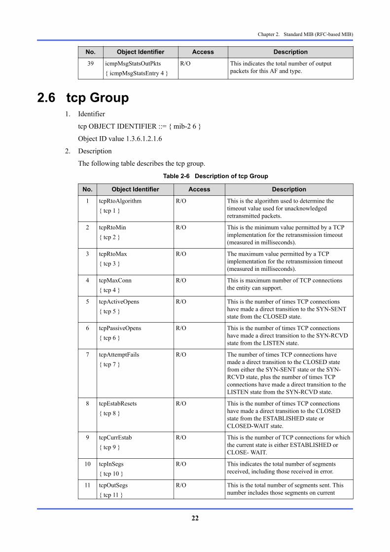
2.6 tcp Group1. Identifier
tcp OBJECT IDENTIFIER ::= { mib-2 6 }
Object ID value 1.3.6.1.2.1.6
2. Description
The following table describes the tcp group.
Table 2-6 Description of tcp Group
No. Object Identifier Access Description
1 tcpRtoAlgorithm{ tcp 1 }
R/O This is the algorithm used to determine thetimeout value used for unacknowledgedretransmitted packets.
2 tcpRtoMin{ tcp 2 }
R/O This is the minimum value permitted by a TCPimplementation for the retransmission timeout(measured in milliseconds).
3 tcpRtoMax{ tcp 3 }
R/O The maximum value permitted by a TCPimplementation for the retransmission timeout(measured in milliseconds).
4 tcpMaxConn{ tcp 4 }
R/O This is maximum number of TCP connectionsthe entity can support.
5 tcpActiveOpens{ tcp 5 }
R/O This is the number of times TCP connectionshave made a direct transition to the SYN-SENTstate from the CLOSED state.
6 tcpPassiveOpens{ tcp 6 }
R/O This is the number of times TCP connectionshave made a direct transition to the SYN-RCVDstate from the LISTEN state.
7 tcpAttemptFails{ tcp 7 }
R/O The number of times TCP connections havemade a direct transition to the CLOSED statefrom either the SYN-SENT state or the SYN-RCVD state, plus the number of times TCPconnections have made a direct transition to theLISTEN state from the SYN-RCVD state.
8 tcpEstabResets{ tcp 8 }
R/O This is the number of times TCP connectionshave made a direct transition to the CLOSEDstate from the ESTABLISHED state orCLOSED-WAIT state.
9 tcpCurrEstab{ tcp 9 }
R/O This is the number of TCP connections for whichthe current state is either ESTABLISHED orCLOSE- WAIT.
10 tcpInSegs{ tcp 10 }
R/O This indicates the total number of segmentsreceived, including those received in error.
11 tcpOutSegs{ tcp 11 }
R/O This is the total number of segments sent. Thisnumber includes those segments on current
Chapter 2. Standard MIB (RFC-based MIB)
22

No. Object Identifier Access Descriptionconnections but excludes those containing onlyretransmitted data.
12 tcpRetransSegs{ tcp 12 }
R/O This is the total number of segmentsretransmitted.
13 tcpConnTable{ tcp 13 }
NA This is a table containing TCP connection-specific information.
14 tcpConnEntry{ tcpConnTable 1 }
NA This is information about a particular currentTCP connection.INDEX {tcpConnLocalAddress,tcpConnLocalPort,tcpConnRemAddress,tcpConnRemPort}
15 tcpConnState{ tcpConnEntry 1 }
R/NW This indicates TCP connection status.
16 tcpConnLocalAddress{ tcpConnEntry 2 }
R/O This indicates the local IP address of the TCPconnection.
17 tcpConnLocalPort{ tcpConnEntry 3 }
R/O This indicates the local port number of the TCPconnection.
18 tcpConnRemAddress{ tcpConnEntry 4 }
R/O This indicates the remote IP address of the TCPconnection.
19 tcpConnRemPort{ tcpConnEntry 5 }
R/O This indicates the remote port number of the TCPconnection.
20 tcpInErrs{ tcp 14 }
R/O This indicates the total number of segmentsreceived in error (checksum errors etc.)
21 tcpOutRsts{ tcp 15 }
R/O This indicates the total number of segmentstransmitted, including RST flags.
22 tcpConnectionTable{ tcp 19 }
NA This is a table containing information aboutexisting TCP connections.
23 tcpConnectionEntry{ tcpConnectionTable 1 }
NA A conceptual row of the tcpConnectionTablecontaining information about a particular currentTCP connection.INDEX {tcpConnectionLocalAddressType,tcpConnectionLocalAddress,tcpConnectionLocalPort,tcpConnectionRemAddressType,tcpConnectionRemAddress,tcpConnectionRemPort}
24 tcpConnectionLocalAddressType{ tcpConnectionEntry 1 }
NA This is the address type oftcpConnectionLocalAddress.INDEX {
Chapter 2. Standard MIB (RFC-based MIB)
23

No. Object Identifier Access DescriptiontcpConnectionLocalAddressType,tcpConnectionLocalAddress,tcpConnectionLocalPort,tcpConnectionRemAddressType,tcpConnectionRemAddress,tcpConnectionRemPort}
25 tcpConnectionLocalAddress{ tcpConnectionEntry 2 }
NA This indicates the local IP address of the TCPconnection.
26 tcpConnectionLocalPort{ tcpConnectionEntry 3 }
NA This indicates the local port number of the TCPconnection.
27 tcpConnectionRemAddressType{ tcpConnectionEntry 4 }
NA This is the address type oftcpConnectionRemAddress.
28 tcpConnectionRemAddress{ tcpConnectionEntry 5 }
NA This indicates the remote IP address of the TCPconnection.
29 tcpConnectionRemPort{ tcpConnectionEntry 6 }
NA This indicates the remote port number of the TCPconnection.
30 tcpConnectionState{ tcpConnectionEntry 7 }
R/W This indicates TCP connection status.
31 tcpConnectionProcess{ tcpConnectionEntry 8 }
R/O This is the system's process ID for the processassociated with this connection. It is zero if thereis no such process.
32 tcpListenerTable{ tcp 20 }
NA This is a table containing information about TCPlisteners.
33 tcpListenerEntry{ tcpListenerTable 1 }
NA A conceptual row of the tcpListenerTablecontaining information about a particular currentTCP connection.INDEX {tcpListenerLocalAddressType,tcpListenerLocalAddress,tcpListenerLocalPort}
34 tcpListenerLocalAddressType{ tcpListenerEntry 1 }
NA This is the address type oftcpListenerLocalAddress.
35 tcpListenerLocalAddress{ tcpListenerEntry 2 }
NA This indicates the local IP address of the TCPconnection.
36 tcpListenerLocalPort{ tcpListenerEntry 3 }
NA This indicates the local port number of the TCPconnection.
37 tcpListenerProcess{ tcpListenerEntry 4 }
R/O This is the system's process ID for the processassociated with this listener, or zero if there is nosuch process.
Chapter 2. Standard MIB (RFC-based MIB)
24

2.7 udp Group1. Identifier
udp OBJECT IDENTIFIER ::= { mib-2 7 }
Object ID value 1.3.6.1.2.1.7
2. Description
The following table describes the udp group.
Table 2-7 Description of udp Group
No. Object Identifier Access Description
1 udpInDatagrams{ udp 1 }
R/O This is the total number of UDP datagramsdelivered to UDP users.
2 udpNoPorts{ udp 2 }
R/O This is the total number of received UDPdatagrams for which there was no application atthe destination port.
3 udpInErrors{ udp 3 }
R/O This is the number of received UDP datagramsthat could not be delivered for reasons other thanthe lack of an application at the destination port.
4 udpOutDatagrams{ udp 4 }
R/O This indicates the total number of UDPdatagrams transmitted from this entity.
5 udpTable{ udp 5 }
NA This is a table containing information aboutlisteners.
6 udpEntry{ udpTable 1 }
NA This is information about a particular currentUDP listener.INDEX { udpLocalAddress, udpLocalPort}
7 udpLocalAddress{ udpEntry 1 }
R/O This is the local IP address for this UDP listener.
8 udpLocalPort{ udpEntry 2 }
R/O This is the local port number for this UDPlistener.
9 udpEndpointTable{ udp 7 }
NA This is a table containing information about thisentity's UDP endpoints on which a localapplication is currently accepting or sendingdatagrams.
10 udpEndpointEntry{ udpEndpointTable 1 }
NA This is information about a particular currentUDP endpoint.INDEX { udpEndpointLocalAddressType, udpEndpointLocalAddress, udpEndpointLocalPort, udpEndpointRemoteAddressType, udpEndpointRemoteAddress, udpEndpointRemotePort, udpEndpointInstance
Chapter 2. Standard MIB (RFC-based MIB)
25

No. Object Identifier Access Description}
11 udpEndpointLocalAddressType{ udpEndpointEntry 1 }
NA This is the address type ofudpEndpointLocalAddress.
12 udpEndpointLocalAddress{ udpEndpointEntry 2 }
NA This indicates the local IP address of the UDPendpoint.
13 udpEndpointLocalPort{ udpEndpointEntry 3 }
NA This indicates the local port number of the UDPendpoint.
14 udpEndpointRemoteAddressType{ udpEndpointEntry 4 }
NA This indicates the address type ofudpEndpointRemoteAddress.
15 udpEndpointRemoteAddress{ udpEndpointEntry 5 }
NA This indicates the remote IP address of the UDPendpoint.
16 udpEndpointRemotePort{ udpEndpointEntry 6 }
NA This indicates the remote port number of theUDP endpoint.
17 udpEndpointInstance{ udpEndpointEntry 7 }
NA This indicates the instance of this tuple.
18 udpEndpointProcess{ udpEndpointEntry 8 }
R/O The system's process ID for the processassociated with this endpoint, or zero if there isno such process.
2.8 transmission Group1. Identifier
transmission OBJECT IDENTIFIER ::= { mib-2 10 }
Object ID value 1.3.6.1.2.1.10
2. Description
The following table describes the transmission group.
Table 2-8 Description of transmission Group
No. Object Identifier Access Description
1 dot3{ transmission 7 }
- This indicates an Ethernet-like statistics group.
2 dot3StatsTable{ dot3 2 }
NA This indicates statistics for a collection ofEthernet-like interfaces attached to a particularsystem.
3 dot3StatsEntry{ dot3StatsTable 1 }
NA This indicates statistics for a particular interfaceto an Ethernet-like medium.INDEX { dot3StatsIndex }
4 dot3StatsIndex{ dot3StatsEntry 1 }
R/O This is an index value that uniquely identifies aninterface to an Ethernet-like medium.
5 dot3StatsAlignmentErrors{ dot3StatsEntry 2 }
R/O This is a total number of frames received on aparticular interface that were not an integral
Chapter 2. Standard MIB (RFC-based MIB)
26

No. Object Identifier Access Descriptionnumber of octets in length and did not pass theFCS check.
6 dot3StatsSingleCollisionFrames{ dot3StatsEntry 4 }
R/O This is a count of successfully transmitted frameson a particular interface for which transmissionhas been inhibited by exactly one collision.
7 dot3StatsMultipleCollisionFrames{ dot3StatsEntry 5 }
R/O A count of successfully transmitted frames on aparticular interface for which transmission isinhibited by more than one collision.
8 dot3StatsLateCollisions{ dot3StatsEntry 8 }
R/O The number of times that a collision is detectedon a particular interface later than 1 slotTime intothe transmission of a packet.
9 dot3StatsExcessiveCollisions{ dot3StatsEntry 9 }
R/O This is the total number of frames failed to betransmitted on a particular interface due toexcessive collisions.
10 dot3StatsDuplexStatus{ dot3StatsEntry 19 }
R/O This is the current mode of operation of the MACentity.
2.9 snmp Group1. Identifier
snmp OBJECT IDENTIFIER ::= { mib-2 11 }
Object ID value 1.3.6.1.2.1.11
2. Description
The following table describes the snmp group.
Table 2-9 Description of snmp Group
No. Object Identifier Access Description
1 snmpInPkts{ snmp 1 }
R/O This is the total number of messages delivered tothe SNMP entity from the transport service.
2 snmpOutPkts{ snmp 2 }
R/O This is the total number of SNMP messageswhich were passed from the SNMP protocolentity to the transport service.
3 snmpInBadVersions{ snmp 3 }
R/O This is the total number of SNMP messageswhich were delivered to the SNMP entity andwere for an unsupported SNMP version.
4 snmpInBadCommunityNames{ snmp 4 }
R/O This is the total number of SNMP messagesdelivered to the SNMP entity which used aninvalid SNMP community name.
5 snmpInBadCommunityUses{ snmp 5 }
R/O This is the total number of SNMP messagesdelivered to the SNMP protocol entity whichrepresented an SNMP operation not allowed bythe SNMP community named in the message.
6 snmpInASNParseErrs{ snmp 6 }
R/O This is the total number of ASN.1 or BER errors detected by the SNMP entitywhen decoding received SNMP messages.
Chapter 2. Standard MIB (RFC-based MIB)
27

No. Object Identifier Access Description
7 snmpInTooBigs{ snmp 8 }
R/O This is the total number of SNMP PDUs whichwere delivered to the SNMP protocol entity andfor which the value of the error-status field is‘tooBig’.
8 snmpInNoSuchNames{ snmp 9 }
R/O This is the total number of SNMP PDUs whichwere delivered to the SNMP protocol entity andfor which the value of the error-status field is‘noSuchName’.
9 snmpInBadValues{ snmp 10 }
R/O This is the total number of SNMP PDUs whichwere delivered to the SNMP protocol entity andfor which the value of the error-status field is‘badValue’.
10 snmpInReadOnlys{ snmp 11 }
R/O This is the total number valid SNMP PDUswhich were delivered to the SNMP protocolentity and for which the value of the error-statusfield is ‘readOnly’.
11 snmpInGenErrs{ snmp 12 }
R/O This is the total number of SNMP PDUs whichwere delivered to the SNMP protocol entity andfor which the value of the error-status field is‘genErr’.
12 snmpInTotalReqVars{ snmp 13 }
R/O This is the total number of MIB objects whichhave been retrieved successfully as a result ofSNMP Get-Request, and Get-Next PDUs.
13 snmpInTotalSetVars{ snmp 14 }
R/O This is the total number of MIB objects whichhave been altered successfully on receipt of anSNMP SetRequest PDU.
14 snmpInGetRequests{ snmp 15 }
R/O This is the total number of SNMP Get-RequestPDUs which have been accepted and processedby the SNMP protocol entity.
15 snmpInGetNexts{ snmp 16 }
R/O This is the total number of SNMP Get-NextPDUs which have been accepted and processedby the SNMP protocol entity.
16 snmpInSetRequests{ snmp 17 }
R/O This indicates the total number of SNMP Set-Request PDUs which have been accepted andprocessed by the SNMP protocol entity.
17 snmpInGetResponses{ snmp 18 }
R/O This indicates the total number of SNMP Get-Response PDUs which have been accepted andprocessed by the SNMP protocol entity.
18 snmpInTraps{ snmp 19 }
R/O This indicates the total number of SNMP TrapPDUs which have been accepted and processedby the SNMP protocol entity.
19 snmpOutTooBigs{ snmp 20 }
R/O This is the total number of SNMP PDUs whichwere generated by the SNMP protocol entity andfor which the value of the error-status field is‘tooBig’.
20 snmpOutNoSuchNames{ snmp 21 }
R/O This is the total number of SNMP PDUs whichwere generated by the SNMP protocol entity andfor which the value of the error-status field is‘noSuchName’.
21 snmpOutBadValues{ snmp 22 }
R/O This is the total number of SNMP PDUs whichwere generated by SNMP protocol entity and for
Chapter 2. Standard MIB (RFC-based MIB)
28

No. Object Identifier Access Descriptionwhich the value of the error-status field is‘badValue’.
22 snmpOutGenErrs{ snmp 24 }
R/O This is the total number of SNMP PDUs whichwere generated by the SNMP protocol entity andfor which the value of the error-status field is‘badValue’.
23 snmpOutGetRequests{ snmp 25 }
R/O This is the total number of SNMP Get-RequestPDUs which have been generated by the SNMPprotocol entity.
24 snmpOutGetNexts{ snmp 26 }
R/O This is the total number of SNMP Get-NextPDUs which have been generated by the SNMPprotocol entity.
25 snmpOutSetRequests{ snmp 27 }
R/O This is the total number of SNMP Set-RequestPDUs which have been generated by the SNMPprotocol entity.
26 snmpOutGetResponses{ snmp 28 }
R/O This is the total number of SNMP Get-ResponsePDUs which have been generated by the SNMPprotocol entity.
27 snmpOutTraps{ snmp 29 }
R/O This is the total number of SNMP Trap PDUswhich have been generated by the SNMPprotocol entity.
28 snmpEnableAuthenTraps{ snmp 30 }
R/W This indicates whether the SNMP agent processis permitted to generate authentication-failuretraps.(Invalid on this system)
29 snmpSilentDrops{ snmp 31 }
R/O This is the total number of PDUs awaiting aresponse (GetRequest-PDUs, GetNextRequest-PDUs, GetBulkRequest-PDUs, SetRequest-PDUs, and InformRequest-PDUs) that werediscarded by destination SNMP entity.The reason for being discarded is that the size ofthe Response Class PDU (Response-PDU etc.)was greater than the maximum message side atthe request originator or exceeded the local limitof the SMTP entity.
30 snmpProxyDrops{ snmp 32 }
R/O This is the total number of PDUs awaiting aresponse (GetRequest-PDUs, GetNextRequest-PDUs, GetBulkRequest-PDUs, SetRequest-PDUs, and InformRequest-PDUs) that werediscarded by destination SNMP entity.The reason for being discarded is that thetransmission of the message to a proxy targetfailed (in a manner other than a time-out) due to,for example, a Response Class PDU (such as aResponse-PDU) not being returned.
2.10 ifMIB Group1. Identifier
ifMIB OBJECT IDENTIFIER ::= { mib-2 31 }
Object ID value 1.3.6.1.2.1.31
Chapter 2. Standard MIB (RFC-based MIB)
29

2. Description
The following table describes the ifMIB group.
Table 2-10 Description of ifMIB Group
No. Object Identifier Access Description
1 ifMIBObjects{ ifMIB 1 }
- -
2 ifXTable{ ifMIBObjects 1 }
NA This is an interface entry list.
3 ifXEntry{ ifXTable 1 }
NA This is an entry containing additionalmanagement information for a specific interface.AUGMENTS { ifEntry }
4 ifName{ ifXEntry 1 }
R/O This indicates an interface name.
5 ifInMulticastPkts{ ifXEntry 2 }
R/O This is the total number of multicast packets,delivered by this sub-layer to a higher(sub-)layer.
6 ifInBroadcastPkts{ ifXEntry 3 }
R/O This is the total number of broadcast packets,delivered by this sub-layer to a higher(sub-)layer.
7 ifOutMulticastPkts{ ifXEntry 4 }
R/O This is the total number of multicast packetsrequested by higher-level protocols. The totalincludes those packets that were discarded or notsent.
8 ifOutBroadcastPkts{ ifXEntry 5 }
R/O This is the total number of broadcast packetsrequested by higher-level protocols. The totalincludes those packets that were discarded or notsent.
9 ifHCInOctets{ ifXEntry 6 }
R/O This is the total number of octets received on theinterface (including framing characters). Thisobject is the 64 bit version of ifInOctets.
10 ifHCInUcastPkts{ ifXEntry 7 }
R/O This is the total number of packets, delivered bythis sub-layer to a higher (sub-)layer, which werenot addressed to a multicast or broadcast addressat this sub-layer. This object is the 64 bit versionof ifInUcastPkts.
11 ifHCInMulticastPkts{ ifXEntry 8 }
R/O This is the total number of packets, delivered bythis sub-layer to a higher (sub-)layer, which werenot addressed to a multicast or broadcast addressat this sub-layer. This object is the 64 bit versionof ifInMulticastPkts.
12 ifHCInBroadcastPkts{ ifXEntry 9 }
R/O This is the total number of packets, delivered bythis sub-layer to a higher (sub-)layer, which werenot addressed to a broadcast address at this sub-layer. This object is the 64 bit version ofifInMulticastPkts.
13 ifHCOutOctets{ ifXEntry 10 }
R/O This is the total number of bytes transmitted outof the interface (including framing characters).This object is the 64 bit version of ifOutOctets.
14 ifHCOutUcastPkts R/O This is the total number of packets that higher-level protocols requested be transmitted, and
Chapter 2. Standard MIB (RFC-based MIB)
30

No. Object Identifier Access Description{ ifXEntry 11 } which were not addressed to a multicast or
broadcast address at this sub-layer. The totalincludes those packets that were discarded or notsent. This object is the 64 bit version ofifOutOctets.
15 ifHCOutMulticastPkts{ ifXEntry 12 }
R/O This is the total number of packets that higher-level protocols requested be transmitted, andwhich were addressed to a multicast or broadcastaddress at this sub-layer. The total includes thosepackets that were discarded or not sent. In theMAC layer protocol, group and functionaddresses are also included. This object is the 64bit version of ifOutMulticastPkts.
16 ifHCOutBroadcastPkts{ ifXEntry 13 }
R/O This is the total number of packets that higher-level protocols requested be transmitted, andwhich were addressed to a broadcast address atthis sub-layer. The total includes those packetsthat were discarded or not sent. This object is the64 bit version of ifOutBroadcastPkts.
17 ifHighSpeed{ ifXEntry 15 }
R/O This is the current estimated bandwidth of theinterface in 1,000,000 bits/second.
18 ifPromiscuousMode{ ifXEntry 16 }
R/W This object has a value of false(2) if this interfaceonly accepts packets/frames that are addressed tothis station. This object has a value of true(1)when the station accepts all packets/frames. Thevalue true(1) is only valid on certain types ofmedia. If valid, it may be necessary to reset theinterface before the object becomes effective.The value of ifPromiscuousMode does not affectthe reception of broadcast and multicast packets/frames by the interface.
19 ifConnectorPresent{ ifXEntry 17 }
R/O This object is true(1) when the interface sub-layer has a physical connector and false(2) if itdoes not.
20 ifAlias{ ifXEntry 18 }
R/W This object is an alias name for the interface andprovides a non-volatile handle for the interface.
21 ifCounterDiscontinuityTime{ ifXEntry 19 }
R/O This is the value of sysUpTime at which any twoor more of this interface's counters suffered adiscontinuity.
22 ifTableLastChange{ ifMIBObjects 5 }
R/O This is the value of sysUpTime at the time of thelast creation or deletion of an entry in the ifTable.
Chapter 2. Standard MIB (RFC-based MIB)
31

Chapter 3. Private MIBThis chapter describes the private MIBs supported by this device.
3.1 Private MIB3.1.1 pf6000System Group
1. Identifier
pf6000System OBJECT IDENTIFIER ::= { pf6000Common-mib 1 }
Object ID value 1.3.6.1.4.1.119.2.3.203.3.2.1
2. Description
The following table describes the pf6000System group.
Table 3-1 Description of pf6000System Group
No. Object Identifier Syntax Access Description
1 pf6000SystemDescription{ pf6000System 1 }
DisplayString R/O This is a description of thesystem.
2 pf6000SystemVersion{ pf6000System 2 }
DisplayString R/O This is the version of the system.
3 pf6000SystemPatchTable{ pf6000System 3 }
- NA This is a table containing patchinformation.
4 pf6000SystemPatchEntry{ pf6000SystemPatchTable 1 }
- NA This is an entry containingspecific patch information.INDEX{ pf6000SystemPatchIndex }
5 pf6000SystemPatchIndex{ pf6000SystemPatchEntry 1 }
INTEGER R/O Patch index number
6 pf6000SystemPatchID{ pf6000SystemPatchEntry 2 }
DisplayString R/O Patch ID
3.1.2 pf6000Resource Group
3.1.2.1 pf6000Cpu Group1. Identifier
pf6000Resource OBJECT IDENTIFIER ::= { pf6000Common-mib 2 }
pf6000Cpu OBJECT IDENTIFIER ::= { pf6000Resource 1 }
Object ID value 1.3.6.1.4.1.119.2.3.203.3.2.2.1
2. Description
The following table describes the pf6000Cpu group.
Chapter 3. Private MIB
32

Table 3-2 Description of pf6000Cpu Group
No. Object Identifier Syntax Access Description
1 pf6000CpuIndex{ pf6000Cpu 1 }
INTEGER R/O This indicates the index numberof the CPU. It is normally zero.
2 pf6000CpuUsageRisingThreshold{ pf6000Cpu 2 }
INTEGER R/O This indicates the threshold valuefor generating an alarm when theCPU load (CPU usage) is high.*1
3 pf6000CpuUsageRisingJudgeTerm{ pf6000Cpu 3 }
INTEGER R/O This indicates the determinationperiod for alarm generation athigh CPU load (in seconds).
4 pf6000CpuUsageFallingThreshold{ pf6000Cpu 4 }
INTEGER R/O This indicates the restorationthreshold value for alarm at highCPU load.
5 pf6000CpuUsageFallingJudgeTerm{ pf6000Cpu 5 }
INTEGER R/O This indicates the determinationperiod for alarm restoration athigh CPU load (in seconds).
6 pf6000CpuUsage{ pf6000Cpu 6 }
INTEGER R/O This indicates the latest CPUusage rate.
7 pf6000CpuUsage1Min{ pf6000Cpu 7 }
INTEGER R/O This indicates the CPU usage rateaveraged over 1 minute.
8 pf6000CpuUsage10Min{ pf6000Cpu 8 }
INTEGER R/O This indicates the CPU usage rateaveraged over 10 minutes.
9 pf6000CpuUsage1Hour{ pf6000Cpu 9 }
INTEGER R/O This indicates the CPU usage rateaveraged over 1 hour.
10 pf6000CpuAlarmStatus{ pf6000Cpu 10 }
INTEGER R/O This is a flag warning of an alarmgeneration status. The flag is 1 infor the alarm generation statusand 0 otherwise.*2
*1 The threshold value and determination period set by the resource monitor command areapplied. When not set, 0 is set.
*2 Use the show alarm status or show alarm history command to check the alarm.
3.1.2.2 pf6000Mem Group1. Identifier
pf6000Resource OBJECT IDENTIFIER ::= { pf6000Common-mib 2 }
pf6000Mem OBJECT IDENTIFIER ::= { pf6000Resource 2 }
Object ID value 1.3.6.1.4.1.119.2.3.203.3.2.2.2
2. Description
The following table describes the pf6000Mem group.
Chapter 3. Private MIB
33

Table 3-3 Description of pf6000Mem Group
No. Object Identifier Syntax Access Description
1 pf6000MemIndex{ pf6000Mem 1 }
INTEGER R/O This indicates the index numberof the memory. It is normallyzero.
2 pf6000MemUsageRisingThreshold{ pf6000Mem 2 }
INTEGER R/O This indicates the threshold valuefor generating an alarm when thememory usage rate is high.*1
3 pf6000MemUsageRisingJudgeTerm{ pf6000Mem 3 }
INTEGER R/O This indicates the determinationperiod for alarm generation athigh memory usage rate (inseconds).
4 pf6000MemUsageFallingThreshold{ pf6000Mem 4 }
INTEGER R/O This indicates the restorationthreshold value for alarm at highmemory usage.
5 pf6000MemUsageFallingJudgeTerm{ pf6000Mem 5 }
INTEGER R/O This indicates the determinationperiod for alarm restoration athigh memory usage rate (inseconds).
6 pf6000MemUsage{ pf6000Mem 6 }
INTEGER R/O This indicates the latest memoryusage rate.
7 pf6000MemUsage1Min{ pf6000Mem 7 }
INTEGER R/O This indicates the memory usagerate averaged over 1 minute.
8 pf6000MemUsage10Min{ pf6000Mem 8 }
INTEGER R/O This indicates the memory usagerate averaged over 10 minutes.
9 pf6000MemUsage1Hour{ pf6000Mem 9 }
INTEGER R/O This indicates the memory usagerate averaged over 1 hour.
10 pf6000MemAlarmStatus{ pf6000Mem 10 }
INTEGER R/O This is a flag warning of an alarmgeneration status. The flag is 1 infor the alarm generation statusand 0 otherwise.*2
*1 The threshold value and determination period set by the resource monitor command areapplied. When not set, 0 is set.
*2 Use the show alarm status or show alarm history command to check alarm.
3.1.2.3 pf6000Disk Group1. Identifier
pf6000Resource OBJECT IDENTIFIER ::= { pf6000Common-mib 2 }
pf6000Disk OBJECT IDENTIFIER ::= { pf6000Resource 3 }
Object ID value 1.3.6.1.4.1.119.2.3.203.3.2.2.3
2. Description
The following table describes the pf6000Disk group.
Chapter 3. Private MIB
34

Table 3-4 Description of pf6000Disk Group
No. Object Identifier Syntax Access Description
1 pf6000DiskTable{ pf6000Disk 1 }
- NA This is a table containing diskinformation.
2 pf6000DiskEntry{ pf6000DiskTable 1 }
- NA This is a list of disk information.INDEX { pf6000DiskIndex }
3 pf6000DiskIndex{ pf6000DiskEntry 1 }
INTEGER R/O This indicates the index numberof the disk.
4 pf6000DiskDeviceName{ pf6000DiskEntry 2 }
DisplayString R/O This indicates the device name ofthe disk.
5 pf6000DiskMountPoint{ pf6000DiskEntry 3 }
DisplayString R/O This indicates the mount pointname of the disk.
6 pf6000DiskSizeLow{ pf6000DiskEntry 4 }
Unsigned32 R/O This indicates the lower-order 32bits of the disk size (in KB).
7 pf6000DiskSizeHigh{ pf6000DiskEntry 5 }
Unsigned32 R/O This indicates the uppermost 32bits of the disk size (in KB).
8 pf6000DiskUsageRisingThreshold{ pf6000DiskEntry 6 }
INTEGER R/O This indicates the threshold valuefor generating an alarm at highdisk usage rate. *1
9 pf6000DiskUsageRisingJudgeTerm{ pf6000DiskEntry 7 }
INTEGER R/O This indicates a determinationperiod for alarm generation athigh disk usage rate (in seconds).
10 pf6000DiskUsageFallingThreshold{ pf6000DiskEntry 8 }
INTEGER R/O This indicates the restorationthreshold value for alarm at highdisk usage rate.
11 pf6000DiskUsageFallingJudgeTerm{ pf6000DiskEntry 9 }
INTEGER R/O This indicates the determinationperiod for alarm restoration athigh disk usage rate (in seconds).
12 pf6000DiskUsage{ pf6000DiskEntry 10 }
INTEGER R/O This indicates the latest diskusage rate.
13 pf6000DiskUsage1Min{ pf6000DiskEntry 11 }
INTEGER R/O This indicates the disk usage rateaveraged over 1 minute.
14 pf6000DiskUsage10Min{ pf6000DiskEntry 12 }
INTEGER R/O This indicates the disk usage rateaveraged over 10 minutes.
15 pf6000DiskUsage1Hour{ pf6000DiskEntry 13 }
INTEGER R/O This indicates the disk usage rateaveraged over 1 hour.
16 pf6000DiskAlarmStatus{ pf6000DiskEntry 14 }
INTEGER R/O This is a flag warning of an alarmgeneration status. The flag is 1 infor the alarm generation statusand 0 otherwise.*2
*1 The threshold value and determination period set by the resource monitor command areapplied. When not set, 0 is set.
*2 Use the show alarm status or show alarm history command to check alarm.
Chapter 3. Private MIB
35

3.1.3 pf6000Application Group
3.1.3.1 pf6000Proc Group1. Identifier
pf6000Application OBJECT IDENTIFIER ::= { pf6000Common-mib 3 }
pf6000Proc OBJECT IDENTIFIER ::= { pf6000Application 1 }
Object ID value 1.3.6.1.4.1.119.2.3.203.3.2.3.1
2. Description
The following table describes the pf6000Proc group.
Table 3-5 Description of pf6000Proc Group
No. Object Identifier Syntax Access Description
1 pf6000ProcTable{ pf6000Proc 1 }
- NA This is a table containing processinformation.
2 pf6000ProcEntry{ pf6000ProcTable 1 }
- NA This is a list of processinformation.INDEX { pf6000ProcIndex }
3 pf6000ProcIndex{ pf6000ProcEntry 1 }
INTEGER R/O This indicates the index numberof the process.
4 pf6000ProcName{ pf6000ProcEntry 2 }
DisplayString R/O This indicates a process name.
5 pf6000ProcStartedDateTime{ pf6000ProcEntry 3 }
DisplayString R/O This indicates a process start dateand time.
6 pf6000ProcStatus{ pf6000ProcEntry 4 }
DisplayString R/O This indicates a process status.
7 pf6000ProcStartCause{ pf6000ProcEntry 5 }
DisplayString R/O This indicates the cause of theprocess startup.
3.1.4 pf6000Cluster Group1. Identifier
pf6000Cluster OBJECT IDENTIFIER ::= { pf6000Common-mib 4 }
Object ID value 1.3.6.1.4.1.119.2.3.203.3.2.4
2. Description
The following table describes the pf6000Cluster group.
Table 3-6 Description of pf6000Cluster Group
No. Object Identifier Syntax Access Description
1 pf6000ClusterStatus{ pf6000Cluster 1 }
INTEGER R/O This indicates the cluster status.
2 pf6000ClusterSwtStatus{ pf6000Cluster 2 }
INTEGER R/O This indicates the clusterswitchover status and whether ornot executed.
Chapter 3. Private MIB
36

No. Object Identifier Syntax Access Description
3 pf6000ClusterSwtPreventCount{ pf6000Cluster 3 }
INTEGER R/O This indicates the number ofreasons that prevented clusterswitching from being executed.
4 pf6000ClusterSwtPreventTable{ pf6000Cluster 4 }
- NA This is a table containing thereasons that prevented clusterswitching from being executed.
5 pf6000ClusterSwtPreventEntry{ pf6000ClusterSwtPreventTable1 }
- NA This is an entry containingspecific reason that preventedcluster switching from beingexecuted.INDEX{ pf6000ClusterSwtPreventIndex}
6 pf6000ClusterSwtPreventIndex{ pf6000ClusterSwtPreventEntry1 }
INTEGER R/O This indicates the index numberof a reason that prevented clusterswitching from being executed.
7 pf6000ClusterSwtPreventReason{ pf6000ClusterSwtPreventEntry2 }
DisplayString R/O This indicates the reason thatprevented cluster switching frombeing executed.
8 pf6000ClusterSwtNeededAction{ pf6000ClusterSwtPreventEntry3 }
DisplayString R/O This indicates the action neededto enable cluster switching.
9 pf6000ClusterNodeCount{ pf6000Cluster 5 }
INTEGER R/O This indicates the number ofnodes that composing the cluster.
10 pf6000ClusterNodeTable{ pf6000Cluster 6 }
- NA This is a table containing clusternode information.
11 pf6000ClusterNodeEntry{ pf6000ClusterNodeTable 1 }
- NA This is an entry containinginformation on specific node ofthe cluster.INDEX{ pf6000ClusterNodeIndex }
12 pf6000ClusterNodeIndex{ pf6000ClusterNodeEntry 1 }
INTEGER R/O This indicates the index numberof node information.
13 pf6000ClusterNodeStatus{ pf6000ClusterNodeEntry 2 }
DisplayString R/O This indicates the node status.
14 pf6000ClusterNodeDateTime{ pf6000ClusterNodeEntry 3 }
DisplayString R/O This indicates the date and timeof node status change.
15 pf6000ClusterNodeName{ pf6000ClusterNodeEntry 4 }
DisplayString R/O This indicates the node name.
16 pf6000ClusterNodeIpAddress{ pf6000ClusterNodeEntry 5 }
InAddress R/O This indicates the node IPaddress.
17 pf6000ClusterNodeVersion{ pf6000ClusterNodeEntry 6 }
DisplayString R/O This indicates the node version.
18 pf6000ClusterUpgFinStatus{ pf6000Cluster 7 }
INTEGER R/O This indicates the finishing statusof software update.
Chapter 3. Private MIB
37

No. Object Identifier Syntax Access Description
19 pf6000ClusterMirDskCount{ pf6000Cluster 8 }
INTEGER R/O This indicates whether or not amirror disk exists.
20 pf6000ClusterMirDskCond{ pf6000Cluster 9 }
DisplayString R/O This indicates the mirror diskstatus.
3.1.5 pf6000PFC Group
3.1.5.1 pf6000FlowEntryMon Group1. Identifier
pf6000PFC OBJECT IDENTIFIER ::= { pf6000Common-mib 5 }
pf6000FlowEntryMon OBJECT IDENTIFIER ::= { pf6000PFC 1 }
Object ID value 1.3.6.1.4.1.119.2.3.203.3.2.5.1
2. Description
The following table describes the pf6000FlowEntryMon group.
Table 3-7 Description of pf6000FlowEntryMon Group
No. Object Identifier Syntax Access Description
1 pf6000FlowEntryMonOFSTable{ pf6000FlowEntryMon 1 }
- NA This is a table that containsinformation on the OFS forwhich flow entry count is to bemonitored.
2 pf6000FlowEntryMonOFSEntry{ pf6000FlowEntryMonOFSTable 1 }
- NA This indicates the index numberof the flow entry countmonitoring information storageentry (on a per-OFS basis).INDEX{ pf6000FlowEntryMonOFSDPID }
3 pf6000FlowEntryMonOFSDPID{ pf6000FlowEntryMonOFSEntry 1 }
OCTET STRING R/O This indicates the DPID of theOFS.
4 pf6000FlowEntryMonOFSModel{ pf6000FlowEntryMonOFSEntry 2 }
DisplayString R/O This indicates the OFS modelname.
5 pf6000FlowEntryMonOFSInterval{ pf6000FlowEntryMonOFSEntry 3 }
INTEGER R/O This indicates the flow entrycount monitoring interval(seconds).
6 pf6000FlowEntryMonTable{ pf6000FlowEntryMon 2 }
- NA This is a table that contains flowentry count monitoringinformation.
7 pf6000FlowEntryMonEntry{ pf6000FlowEntryMonTable 1 }
- NA This is the flow entry countmonitoring information storageentry.
Chapter 3. Private MIB
38

No. Object Identifier Syntax Access DescriptionINDEX{ pf6000FlowEntryMonDPID,pf6000FlowEntryMonIndex}
8 pf6000FlowEntryMonIndex{ pf6000FlowEntryMonEntry 1 }
INTEGER R/O This indicates the index numberof the flow entry countmonitoring information storageentry.
9 pf6000FlowEntryMonDPID{ pf6000FlowEntryMonEntry 2 }
OCTET STRING R/O This indicates the DPID of theOFS.
10 pf6000FlowEntryMonTarget{ pf6000FlowEntryMonEntry 3 }
DisplayString R/O This indicates the monitoringtarget (flow table ID, flow tablename, flow entry type).The value returned is the same asthat displayed for Target: of theshow flow-entry-monitorcommand.
11 pf6000FlowEntryMonStatus{ pf6000FlowEntryMonEntry 4 }
INTEGER R/O This indicates the flow entrycount monitoring status:0: The threshold value is notexceeded.1: The threshold value isexceeded.-1: Data not collected
12 pf6000FlowEntryMonRising{ pf6000FlowEntryMonEntry 5 }
INTEGER R/O This indicates the threshold valuefor alarm generation (flow entrycount).
13 pf6000FlowEntryMonFalling{ pf6000FlowEntryMonEntry 6 }
INTEGER R/O This indicates the threshold valuefor recovery from an alarm (flowentry count).
14 pf6000FlowEntryMonLast{ pf6000FlowEntryMonEntry 7 }
INTEGER R/O This indicates the most-recentlymonitored flow entry count.
15 pf6000FlowEntryMonMax{ pf6000FlowEntryMonEntry 8 }
INTEGER R/O This indicates the maximum flowentry count (statistical value).
16 pf6000FlowEntryMonMaxOccured{ pf6000FlowEntryMonEntry 9 }
DisplayString R/O This indicates the date and timeof the maximum flow entry countgeneration.
17 pf6000FlowEntryMonAlarmOccured{ pf6000FlowEntryMonEntry10 }
DisplayString R/O This indicates the date and timeof the flow entry countmonitoring alarm generation.
18 pf6000FlowEntryMonAlarmRecovered{ pf6000FlowEntryMonEntry11 }
DisplayString R/O This indicates the date and timeof the recovery from a flow entrycount monitoring alarm.
Chapter 3. Private MIB
39

3.1.5.2 pf6000Trmon Group
pf6000TrmonPF52 Group1. Identifier
pf6000Trmon OBJECT IDENTIFIER ::= { pf6000PFC 2 }
pf6000TrmonPF52 OBJECT IDENTIFIER ::= { pf6000Trmon 1 }
Object ID value 1.3.6.1.4.1.119.2.3.203.3.2.5.2.1
2. Description
pf6000Trmon is a group for acquiring statistics of the virtual network.
The Pf6000Trmon group has the pf6000TrmonPF52 group. The pf6000TrmonPF52 group is anMIB to acquire incoming traffic for VTN, vBridge, and vExternal by using the QoS Table ofPF5200 series and the policing feature of this product.
To use this MIB, PFC must be configured as follows:
a. To get statistics of QoS (policing) configuration:
Configure only existing PFC.
b. To get statistics without QoS (policing)
Configure the policing as follows:
i. flow-list command: Specify the flow list for acquiring statistics.
Specify sequence-number and set the flow match condition. To monitor multipleflows, specify multiple sequence-numbers.
To set the match condition by using this MIB, specify sequence-number only. Donot specify the match condition.
ii. policing profile command: Specify the policing profile for acquiring statistics.
Specify sequence-number and set the flow list for acquiring statistics as thepolicing condition (match flow-list command). Specify "pass" for all policingactions (green-action, yellow-action, and red-action commands). Specify "1pps"for all policing rates (meter command).
This enables normal data transfer even if the policing condition is satisfied.
iii. Specify the policing profile for a virtual node to get statistics.
Note the following for this MIB:
a. Every time a flow that matches the policing configuration occurs, PFC registers the flowentry for policing on the PF5200 series where the flow is detected. The flow entry isregistered with combination of a DPID, physical port, and VLAN. No more than 1K offlow entries are available for PF5240 and PF5248. For more than 1K of flow entries,subsequent flow entries are not registered on the PFS, and statistics may show smallervalues than actual values.
b. In case that the flow entry for policing overflowed,pf6000sPombasePolicerFullOccuWaO SNMP TRAP is sent. Monitor this TRAP as well.
c. The statistics of this MIB is provided by acquiring flow information on the PF5200series. To reduce the load of the PFS, SNMP managers should avoid continuousacquisition.
Chapter 3. Private MIB
40

pf6000TrmonPF52 consists of the following groups:
• pf6000TrmonPF52Vtn
• pf6000TrmonPF52Vbridge
• pf6000TrmonPF52Vexternal
• pf6000TrmonPF52Condition
The following tables shows the description of each group.
Table 3-8 Description of pf6000TrmonPF52Vtn Group
No. Object Identifier Syntax Access Description
1 pf6000TrmonPF52VtnTable{ pf6000TrmonPF52Vtn 1 }
- NA Table for storing VTNinformation of which statisticscan be acquired.
2 pf6000TrmonPF52VtnEntry{ pf6000TrmonPF52VtnTable 1 }
- NA This indicates indexes of VTNstatistics entries.INDEX{ pf6000TrmonPF52VtnName,pf6000TrmonPF52VtnSeqNum }
3 pf6000TrmonPF52VtnName{ pf6000TrmonPF52VtnEntry 1 }
DisplayString R/O This indicates VTN name ofwhich statistics can be acquired.
4 pf6000TrmonPF52VtnSeqNum{ pf6000TrmonPF52VtnEntry 2 }
INTEGER R/O This indicates the sequence-number specified in policingconfiguration.
5 pf6000TrmonPF52VtnGreenAction{ pf6000TrmonPF52VtnEntry 3 }
INTEGER R/O This indicates the Green actionspecified in policingconfiguration.
6 pf6000TrmonPF52VtnYellowAction{ pf6000TrmonPF52VtnEntry 4 }
INTEGER R/O This indicates the Yellow actionspecified in policingconfiguration.
7 pf6000TrmonPF52VtnRedAction{ pf6000TrmonPF52VtnEntry 5 }
INTEGER R/O This indicates the Red actionspecified in policingconfiguration.
8 pf6000TrmonPF52VtnTotalPackets{ pf6000TrmonPF52VtnEntry 6 }
Counter64 R/O This indicates the total number ofincoming packets of the Policerspecified for INDEX.
9 pf6000TrmonPF52VtnTotalOctets{ pf6000TrmonPF52VtnEntry 7 }
Counter64 R/O This indicates the total number ofincoming octets of the Policerspecified for INDEX.
10 pf6000TrmonPF52VtnGreenYellowPackets{ pf6000TrmonPF52VtnEntry 8 }
Counter64 R/O This indicates the number ofincoming packets that matchedthe Green or Yellow action of thePolicer specified for INDEX.
11 pf6000TrmonPF52VtnGreenYellowOctets{ pf6000TrmonPF52VtnEntry 9 }
Counter64 R/O This indicates the number ofincoming octets that matched theGreen or Yellow action of thePolicer specified for INDEX.
12 pf6000TrmonPF52VtnRedPackets
Counter64 R/O This indicates the number ofincoming packets that matchedthe Red action of the Policerspecified for INDEX.
Chapter 3. Private MIB
41

No. Object Identifier Syntax Access Description{ pf6000TrmonPF52VtnEntry10 }
13 pf6000TrmonPF52VtnRedOctets{ pf6000TrmonPF52VtnEntry11 }
Counter64 R/O This indicates the number ofincoming octets that matched theRed action of the Policerspecified for INDEX.
14 pf6000TrmonPF52VtnDate{ pf6000TrmonPF52VtnEntry12 }
DisplayString R/O This indicates the acquisitiontime of the entry information.This entry may indicate a timebefore the last acquisition timedue to time compensation byPFC.
Table 3-9 Description of pf6000TrmonPF52Vbridge Group
No. Object Identifier Syntax Access Description
1 pf6000TrmonPF52VbridgeTable{ pf6000TrmonPF52Vbridge 1 }
- NA Table for storing vBridgeinformation of which statisticscan be acquired.
2 pf6000TrmonPF52VbridgeEntry{ pf6000TrmonPF52VbridgeTable 1 }
- NA This indicates an index ofvBridge statistics entry.INDEX{ pf6000TrmonPF52VbridgeVtnName,pf6000TrmonPF52VbridgeName,pf6000TrmonPF52VbridgeSeqNum }
3 pf6000TrmonPF52VbridgeVtnName{ pf6000TrmonPF52VbridgeEntry 1 }
DisplayString R/O This indicates VTN name ofwhich statistics can be acquired.
4 pf6000TrmonPF52VbridgeName{ pf6000TrmonPF52VbridgeEntry 2 }
DisplayString R/O This indicates vBridge name ofwhich statistics can be acquired.
5 pf6000TrmonPF52VbridgeSeqNum{ pf6000TrmonPF52VbridgeEntry 3 }
INTEGER R/O This indicates the sequence-number specified in policingconfiguration.
6 pf6000TrmonPF52VbridgeGreenAction{ pf6000TrmonPF52VbridgeEntry 4 }
INTEGER R/O This indicates the Green actionspecified in policingconfiguration.
7 pf6000TrmonPF52VbridgeYellowAction{ pf6000TrmonPF52VbridgeEntry 5 }
INTEGER R/O This indicates the Yellow actionspecified in policingconfiguration.
8 pf6000TrmonPF52VbridgeRedAction{ pf6000TrmonPF52VbridgeEntry 6 }
INTEGER R/O This indicates the Red actionspecified in policingconfiguration.
Chapter 3. Private MIB
42

No. Object Identifier Syntax Access Description
9 pf6000TrmonPF52VbridgeTotalPackets{ pf6000TrmonPF52VbridgeEntry 7 }
Counter64 R/O This indicates the total number ofincoming packets of the Policerspecified for INDEX.
10 pf6000TrmonPF52VbridgeTotalOctets{ pf6000TrmonPF52VbridgeEntry 8 }
Counter64 R/O This indicates the total number ofincoming octets of the Policerspecified for INDEX.
11 pf6000TrmonPF52VbridgeGreenYellowPackets{ pf6000TrmonPF52VbridgeEntry 9 }
Counter64 R/O This indicates the number ofincoming packets that matchedthe Green or Yellow action of thePolicer specified for INDEX.
12 pf6000TrmonPF52VbridgeGreenYellowOctets{ pf6000TrmonPF52VbridgeEntry 10 }
Counter64 R/O This indicates the number ofincoming octets that matched theGreen or Yellow action of thePolicer specified for INDEX.
13 pf6000TrmonPF52VbridgeRedPackets{ pf6000TrmonPF52VbridgeEntry 11 }
Counter64 R/O This indicates the number ofincoming packets that matchedthe Red action of the Policerspecified for INDEX.
14 pf6000TrmonPF52VbridgeRedOctets{ pf6000TrmonPF52VbridgeEntry 12 }
Counter64 R/O This indicates the number ofincoming octets that matched theRed action of the Policerspecified for INDEX.
15 pf6000TrmonPF52VbridgeDate{ pf6000TrmonPF52VbridgeEntry 13 }
DisplayString R/O This indicates the acquisitiontime of the entry information.This may indicates a time beforethe last acquisition time due totime compensation by PFC.
Table 3-10 Description of pf6000TrmonPF52Vexternal Group
No. Object Identifier Syntax Access Description
1 pf6000TrmonPF52VexternalTable{ pf6000TrmonPF52Vexternal1 }
- NA Table for storing vExternalinformation of which statisticscan be acquired.
2 pf6000TrmonPF52VexternalEntry{ pf6000TrmonPF52VexternalTable 1 }
- NA This indicates an index ofvExternal statistics entry.INDEX{ pf6000TrmonPF52VexternalVtnName,pf6000TrmonPF52VexternalName,pf6000TrmonPF52VexternalSeqNum }
3 pf6000TrmonPF52VexternalVtnName{ pf6000TrmonPF52VexternalEntry 1 }
DisplayString R/O This indicates VTN name ofwhich statistics can be acquired.
Chapter 3. Private MIB
43

No. Object Identifier Syntax Access Description
4 pf6000TrmonPF52VexternalName{ pf6000TrmonPF52VexternalEntry 2 }
DisplayString R/O This indicates vExternal name ofwhich statistics can be acquired.
5 pf6000TrmonPF52VexternalSeqNum{ pf6000TrmonPF52VexternalEntry 3 }
INTEGER R/O This indicates the sequence-number specified in policingconfiguration.
6 pf6000TrmonPF52VexternalGreenAction{ pf6000TrmonPF52VexternalEntry 4 }
INTEGER R/O This indicates the Green actionspecified in policingconfiguration.
7 pf6000TrmonPF52VexternalYellowAction{ pf6000TrmonPF52VexternalEntry 5 }
INTEGER R/O This indicates the Yellow actionspecified in policingconfiguration.
8 pf6000TrmonPF52VexternalRedAction{ pf6000TrmonPF52VexternalEntry 6 }
INTEGER R/O This indicates the Red actionspecified in policingconfiguration.
9 pf6000TrmonPF52VexternalTotalPackets{ pf6000TrmonPF52VexternalEntry 7 }
Counter64 R/O This indicates the total number ofincoming packets of the Policerspecified for INDEX.
10 pf6000TrmonPF52VexternalTotalOctets{ pf6000TrmonPF52VexternalEntry 8 }
Counter64 R/O This indicates the total number ofincoming octets of the Policerspecified for INDEX.
11 pf6000TrmonPF52VexternalGreenYellowPackets{ pf6000TrmonPF52VexternalEntry 9 }
Counter64 R/O This indicates the number ofincoming packets that matchedthe Green or Yellow action of thePolicer specified for INDEX.
12 pf6000TrmonPF52VexternalGreenYellowOctets{ pf6000TrmonPF52VexternalEntry 10 }
Counter64 R/O This indicates the number ofincoming octets that matched theGreen or Yellow action of thePolicer specified for INDEX.
13 pf6000TrmonPF52VexternalRedPackets{ pf6000TrmonPF52VexternalEntry 11 }
Counter64 R/O This indicates the number ofincoming packets that matchedthe Red action of the Policerspecified for INDEX.
14 pf6000TrmonPF52VexternalRedOctets{ pf6000TrmonPF52VexternalEntry 12 }
Counter64 R/O This indicates the number ofincoming octets that matched theRed action of the Policerspecified for INDEX.
15 pf6000TrmonPF52VexternalDate{ pf6000TrmonPF52VexternalEntry 13 }
DisplayString R/O This indicates the acquisitiontime of the entry information.This may entry indicate a timebefore the last acquisition time
Chapter 3. Private MIB
44

No. Object Identifier Syntax Access Descriptiondue to time compensation byPFC.
Table 3-11 Description of pf6000TrmonPF52Condition Group
No. Object Identifier Syntax Access Description
1 pf6000TrmonPF52ConditionTable{ pf6000TrmonPF52Condition1 }
- NA Table for changing a target flowto acquire statistics.
2 pf6000TrmonPF52ConditionEntry{ pf6000TrmonPF52ConditionTable 1 }
- NA This indicates an index of targetflow entry of statistics.INDEX{ pf6000TrmonPF52ConditionPolicingMap,pf6000TrmonPF52PolicerSeqNum,pf6000TrmonPF52ConditionFlowlistSeqNum }
3 pf6000TrmonPF52ConditionPolicingMap{ pf6000TrmonPF52ConditionEntry 1 }
DisplayString R/O This indicates the Policing profilename for which you want tochange a target flow to acquirestatistics.
4 pf6000TrmonPF52ConditionPolicerSeqNum{ pf6000TrmonPF52ConditionEntry 2 }
INTEGER R/O This indicates the sequence-number specified in policingconfiguration.
5 pf6000TrmonPF52ConditionFlowlistSeqNum{ pf6000TrmonPF52ConditionEntry 3 }
INTEGER R/O This indicates the sequence-number in the flow-list specifiedin policing configuration.
6 pf6000TrmonPF52ConditionSrcIpAddr{ pf6000TrmonPF52ConditionEntry 4 }
IpAddress R/W Specifies the source IP addressthat can be acquired.
7 pf6000TrmonPF52ConditionSrcIpPrefix{ pf6000TrmonPF52ConditionEntry 5 }
INTEGER R/W Specifies the prefix length of thesource IP address that can beacquired.
8 pf6000TrmonPF52ConditionDstIpAddr{ pf6000TrmonPF52ConditionEntry 6 }
IpAddress R/W Specifies the destination IPaddress that can be acquired.
9 pf6000TrmonPF52ConditionDstIpPrefix{ pf6000TrmonPF52ConditionEntry 7 }
INTEGER R/W Specifies the prefix length of thedestination IP address that can beacquired.
10 pf6000TrmonPF52ConditionProtocol{ pf6000TrmonPF52ConditionEntry 8 }
INTEGER R/W Specifies the number of aprotocol such as TCP and UDPthat can be acquired.
Chapter 3. Private MIB
45

No. Object Identifier Syntax Access Description
11 pf6000TrmonPF52ConditionSrcL4Port{ pf6000TrmonPF52ConditionEntry 9 }
INTEGER R/W Specifies the source TCP/IP portnumber that can be acquired.
12 pf6000TrmonPF52ConditionDstL4Port{ pf6000TrmonPF52ConditionEntry 10 }
INTEGER R/W Specifies the destination TCP/IPport number that can be acquired.
13 pf6000TrmonPF52ConditionAdminStatus{ pf6000TrmonPF52ConditionEntry 11 }
INTEGER R/W This applies the setting to thecandidate-configuration andspecifies commit.(1) Set all the MIB values that arealready set in this table to thecandidate-configuration and thencommit them.(2) Delete all the flow-listsettings that can be specified bythis table from the candidate-configuration and then committhem.The candidate-configuration isnot changed and commit is notrun until this value is updated.
Information configured by pf6000TrmonPF52Condition is saved in the PFC running-configuration, but not in the startup-configuration. Therefore, values specified in this MIB willbe deleted at restart of PFC.
ImportantTo use the pf6000TrmonPF52Condition group, consider permissions and usage by consultingnetwork system designers.In pf6000TrmonPF52Condition configuration, provided QoS policing configuration for controllingthe rate exists in the same policing profile, the policing flow is also used for acquiring statistics.Therefore, the number of flows available for controlling the rate decreases, and this may affect ratecontrol operation.
TipIn the case of a large PFC configuration, the processing of this MIB may take a considerable time andcause a time-out on the SNMP manager. Should this occur, execute the MIB operation again.
3.1.6 pf6000NotificationObjects Group1. Identifier
pf6000NotificationObjects OBJECT IDENTIFIER ::= { pf6000-mib 1 }
Object ID value 1.3.6.1.4.1.119.2.3.203.3.1
2. Description
The following table describes the pf6000NotificationObjects group.
Chapter 3. Private MIB
46

Table 3-12 Description of pf6000NotificationObjects Group
No. Object Identifier Syntax Access Description
1 pf6000AlarmDateTime{ pf6000NotificationObjects 1 }
DisplayString AN This indicates a date and time ofalarm generation.
2 pf6000AlarmComponentId{ pf6000NotificationObjects 2 }
INTEGER AN This is the ID of the componentthat generated the alarm.
3 pf6000AlarmCategory{ pf6000NotificationObjects 3 }
INTEGER AN This indicates the category of thealarm.
4 pf6000AlarmClass{ pf6000NotificationObjects 4 }
INTEGER AN This indicates the class of thealarm.
5 pf6000AlarmKind{ pf6000NotificationObjects 5 }
INTEGER AN This indicates the kind of thealarm.
6 pf6000AlarmInfoString{ pf6000NotificationObjects 6 }
DisplayString AN This is a character string foridentifying the alarm.
7 pf6000AlarmMessageSummary{ pf6000NotificationObjects 7 }
DisplayString AN This is a summary of the alarmmessage.
8 pf6000AlarmMessage{ pf6000NotificationObjects 8 }
DisplayString AN This indicates the alarm message.
9 pf6000AlarmVTNName{ pf6000NotificationObjects 9 }
DisplayString AN This is the VTN name thatgenerated the alarm.
10 pf6000ColdStartReason{ pf6000NotificationObjects100 }
DisplayString AN This indicates the reason for theColdStart.
11 pf6000IfUse{ pf6000NotificationObjects200 }
DisplayString AN This indicates the usage of thenetwork interface. For aninterface related to clusterinterconnect, “Clusterinterconnect” is set. For othercases, an empty string is set.
12 pf6000IfBonding{ pf6000NotificationObjects201 }
DisplayString AN This indicates information aboutthe Bonding interface.
13 pf6000ClusterFailureMessage{ pf6000NotificationObjects1601010220 }
DisplayString AN This is a ClusterFailure message.
14 pf6000ClusterTransitionMessage2{ pf6000NotificationObjects1603010520 }
DisplayString AN This is a ClusterTransitionmessage.
Chapter 3. Private MIB
47

Chapter 4. Support MIB TrapsThis chapter describes the traps supported by this device.
4.1 Support Traps and Triggers for Generation4.1.1 Private MIB Traps
The following table describes private MIB support traps and triggers for generation.
TipFor the level of importance and action for each trap, refer to 2.1 Alarms and Traps in the Log MessageReference.
Table 4-1 Private MIB Support Traps and Triggers for Generation
No. Type of Trap Meaning Trigger for Generation
1 coldStart SNMP function has started. (1) When the SNMP function hasbeen enabled by the snmp-agentenable command.(2) When PFC has been restartedwith the snmp-agent enablecommand registered in thestartup-configuration.(3) When a cluster node hasswitched over from an activenode to a standby node with the snmp-agent enable commandregistered in the startup-configuration.
2 pf6000ColdStart SNMP function has started. (1) When the SNMP function hasbeen enabled by the snmp-agentenable command.(2) When PFC has been restartedwith the snmp-agent enablecommand registered in thestartup-configuration.(3) When cluster node hasswitched over from active node tostandby node with the snmp-agent enable command registeredin the startup-configuration.
3 pf6000sVtnctlVTNFaultWaO There is one or more than one pathover which it is not possible tocommunicate with vtn=<value>.
When failure has occurred on oneor more of the vtn=<value> paths.
4 pf6000sVtnctlVTNFaultNoR Recovered from all failures on thepaths to vtn=<value>.
When system has recovered fromall failures on the paths tovtn=<value>.
5 pf6000sNomgSWStartNoN PFC Server Software has started. When PFC Server Software hasstarted.
Chapter 4. Support MIB Traps
48

No. Type of Trap Meaning Trigger for Generation
6 pf6000sNomgSWStartFailAlN Startup of PFC Server Software hasfailed.
When startup of PFC ServerSoftware has failed.
7 pf6000sNomgSWStopNoN PFC Server Software has stopped. When PFC Server Software hasstopped.
8 pf6000sNomgSWAbortAlN PFC Server Software has beenaborted due to an error.
When PFC Server Software hasbeen aborted due to an error.
9 pf6000sNomgSWRestartNoN PFC Server Software has restarted. When PFC Server Software hasrestarted.
10 pf6000sNomgSWRestartFailAlN Restart of PFC Server Software hasfailed.
When restart of PFC ServerSoftware has failed.
11 pf6000sNomgServerRebootAlN PFC Server rebooted because of therestart level3.
When PFC Server Software hasbeen aborted due to an error atrestart level 3.
12 pf6000sNomgSWStopAlN Stopped PFC Server rebootingbecause of the restart level 4.
When PFC Server Software hasbeen aborted due to an error atrestart level 4.
13 pf6000sResmgrCpuUsageRiseWaO
CPU usage on the PFC Server hasexceeded the upper threshold.
When CPU usage on the PFCServer has exceeded the upperthreshold.
14 pf6000sResmgrCpuUsageFallNoR (1) CPU usage on the PFC Serverhas dropped below the lowerthreshold.(2) As the settings for themonitoring threshold for CPUusage on the PFC Server weredeleted, decisions about high loadhave stopped.
(1) CPU usage on the PFC Serverhas dropped below the lowerthreshold.When the threshold value settingis deleted with the system in astate in which CPU usage on thePFC Server has exceeded theupper threshold value.
15 pf6000sResmgrMemUsageRiseWaO
Physical memory usage on the PFCServer has exceeded the upperthreshold value.
When physical memory usage onthe PFC Server has exceeded theupper threshold value.
16 pf6000sResmgrMemUsageFallNoR
(1) Physical memory usage on thePFC Server has dropped below thelower threshold value.(2) As the settings for themonitoring threshold for physicalmemory usage on the PFC Serverwere deleted, decisions about highload have stopped.
(1) Physical memory usage on thePFC Server has dropped belowthe lower threshold value.(2) When the threshold valuesetting is deleted with the systemin a state in which physicalmemory usage on the PFC Serverhas exceeded the upper thresholdvalue.
17 pf6000sResmgrDiskUsageRiseWaO
Disk usage on the PFC Server hasexceeded the upper threshold value.
When disk usage on the PFCServer has exceeded the upperthreshold value.
18 pf6000sResmgrDiskUsageFallNoR
(1) Disk usage on the PFC Serverhas dropped below the lowerthreshold value.(2) As the settings for themonitoring threshold for disk usageon the PFC server were deleted,decisions about high load havestopped.
(1) When disk usage on the PFCServer has dropped below thelower threshold value.(2) When the threshold valuesetting is deleted with the systemin a state in which disk usage onthe PFC Server has exceeded theupper threshold value.
Chapter 4. Support MIB Traps
49

No. Type of Trap Meaning Trigger for Generation
19 pf6000sResmgrDiskFailErO Failed to get information about thePFC Server disk.
When system cannot getinformation about the PFC Serverdisk.
20 pf6000sResmgrDiskRecoverNoR Recovered from the failure to getinformation about the PFC Serverdisk.
When system has recovered fromthe failure to get informationabout the PFC Server disk.
21 pf6000sAplmgrProcStartNoN PFC process has started. When a PFC process has started.
22 pf6000sAplmgrProcStartFailAlO PFC process has failed to start.(Level of Importance: alert)
When PFC process has failed tostart. (Level of Importance: alert)
23 pf6000sAplmgrProcStartFailCrO PFC process has failed to start.(Level of Importance: critical)
When PFC process has failed tostart. (Level of Importance:critical)
24 pf6000sAplmgrProcStartFailErO PFC process has failed to start.(Level of Importance: error)
When PFC process has failed tostart. (Level of Importance: error)
25 pf6000sAplmgrProcStartFailWaO PFC process has failed to start.(Level of Importance: warning)
When PFC process has failed tostart. (Level of Importance:warning)
26 pf6000sAplmgrProcStartFailNoO PFC process has failed to start.(Level of Importance: notice)
When PFC process has failed tostart. (Level of Importance:notice)
27 pf6000sAplmgrProcStartTimeoutAlO
PFC process has timed out. (Levelof Importance: alert)
When PFC process has timed out.(Level of Importance: alert)
28 pf6000sAplmgrProcStartTimeoutCrO
PFC process has timed out. (Levelof Importance: critical)
When PFC process has timed out.(Level of Importance: critical)
29 pf6000sAplmgrProcStartTimeoutErO
PFC process has timed out. (Levelof Importance: error)
When PFC process has timed out.(Level of Importance: error)
30 pf6000sAplmgrProcStartTimeoutWaO
PFC process has timed out. (Levelof Importance: warning)
When PFC process has timed out.(Level of Importance: warning)
31 pf6000sAplmgrProcStartTimeoutNoO
PFC process has timed out. (Levelof Importance: notice)
When PFC process has timed out.(Level of Importance: notice)
32 pf6000sAplmgrProcStopNoN PFC process has stopped. When PFC process has stopped.
33 pf6000sAplmgrProcStopFailWaO PFC process has failed to stop. When PFC process has failed tostop.
34 pf6000sAplmgrProcStopTimeoutWaO
PFC process stop has timed out. When PFC process stop hastimed out.
35 pf6000sAplmgrProcAbortAlO PFC process has aborted. (Level ofImportance: alert)
When PFC process has stopped.(Level of Importance: alert)
36 pf6000sAplmgrProcAbortCrO PFC process has aborted. (Level ofImportance: critical)
When PFC process has stopped.(Level of Importance: critical)
37 pf6000sAplmgrProcAbortErO PFC process has aborted. (Level ofImportance: error)
When PFC process has stopped.(Level of Importance: error)
38 pf6000sAplmgrProcAbortWaO PFC process has aborted. (Level ofImportance: warning)
When PFC process has stopped.(Level of Importance: warning)
39 pf6000sAplmgrProcAbortNoO PFC process has aborted. (Level ofImportance: notice)
When PFC process has stopped.(Level of Importance: notice)
40 pf6000sViewgaFlowThresholdOWaO
The upper threshold value of sFlowhas been exceeded.
When sFlow of ofs=<value> INIF=<value> srcIP=<value>dstIP=<value> srcPort=<value>
Chapter 4. Support MIB Traps
50

No. Type of Trap Meaning Trigger for GenerationdstPort=<value> setting=<value>over=<value> has exceeded thethreshold value.
41 pf6000sViewgaFlowThresholdRNoR
The sFlow value has droppedbelow the lower threshold value.
When sFlow of ofs=<value> INIF=<value> srcIP=<value>dstIP=<value> srcPort=<value>dstPort=<value> has droppedbelow the lower threshold value.
42 pf6000sPthctlPhysPathFaultWaO A path failure has occurred fromIngress ofs=<value> to Egressofs=<value> in path policy<index>.
When a path failure has occurreddue to the lack of a valid pathfrom Ingress ofs=<value> toEgress ofs=<value> in pathpolicy<index>.
43 pf6000sPthctlPhysPathFaultNoR Recovered from a path failure fromIngress ofs=<value> to Egressofs=<value> in path policy<index>.
When a path from Ingressofs=<value> to Egressofs=<value> has become usablein path policy<index>.
44 pf6000sPthctlFlowEntFullOccurWaO
A flow settings overflow toOFS=<value> has occurred.
When a flow settings overflow toOFS=<value> has occurred.
45 pf6000sPthctlFlowEntFullRecovNoR
The flow settings of OS=<value>are successful, and the system hasrecovered from the settingsoverflow.
When the system has successfullyset the flow settings to OFS, andthe system has recovered fromthe settings overflow.
46 pf6000sPthctlOFSDomMissLinkOWaO
The misconnection link betweenthe OFS domain ofdomain1=<value> and the OFSdomain of domain2=<value>occurred.
When any connection linkspanning OFS domains betweendomain1=<value> ofs1=<value>port1=<value> anddomain2=<value> ofs2=<value>port2=<value> is detected.
47 pf6000sPthctlOFSDomMissLinkRNoR
The misconnection link betweenthe OFS domain ofdomain1=<value> and the OFSdomain of domain2=<value> hasrecovered.
(1) When any connection linkspanning OFS domains betweendomain1=<value> ofs1=<value>port1=<value> anddomain2=<value> ofs2=<value>port2=<value> is cleared.(2) When ofs1=<value> andofs2=<value> are in the sameOFS domain.
48 pf6000sPthctlSubdomMissLinkOWaO
A misconnection link between theOFS subdomain or OFS coredomain of sub1=<value> and theOFS subdomain of sub2=<value>occurred.
(1) When a connection link isdetected spanning OFSsubdomains betweensub1=<value> ofs1=<value>port1=<value> and sub2=<value>ofs2=<value> port2=<value> inthe OFS domain ofdomain=<value>.(2) When any connection linkbetween sub1=OFS Core Domainofs1=<value> port1=<value> andsub2=<value> ofs2=<value>port2=<value> in the OFSdomain of domain=<value>without OFS subdomain gatewayconfiguration is cleared.
Chapter 4. Support MIB Traps
51

No. Type of Trap Meaning Trigger for Generation
49 pf6000sPthctlSubdomMissLinkRNoR
The misconnection link betweenthe OFS subdomain or OFS coredomain of sub1=<value> and theOFS subdomain of sub2=<value>has recovered.
When there is no connectionspanning OFS subdomainsbetween sub1=<value>ofs1=<value> port1=<value> andsub2=<value> ofs2=<value>port2=<value> in the OFSdomain of domain=<value>, andthere is no connection linkbetween ofs1=<value>port1=<value> and sub2=<value>ofs2=<value> port2=<value> inthe OFS domain ofdomain=<value>.
50 pf6000sPthctlCoreDomainSplitWaO
The broadcast delivery network ofthe OFS domain ofdomain=<value> is disconnected.
When the broadcast deliverynetwork of the OFS core domainof the domain=<value> OFSdomain is disconnected.
51 pf6000sPthctlCoreDomainRecovNoR
Disconnection of the broadcastdelivery network of the OFSdomain of domain=<value> isrecovered.
When the broadcast deliverynetwork of the OFS core domainof the domain=<value> OFSdomain.
52 pf6000sPthctlSubdomainSplitWaO The broadcast delivery network ofthe OFS subdomain ofsubdomain=<value> in the OFSdomain of domain=<value> isdisconnected.
(1) When the broadcast deliverynetwork of thesubdomain=<value> OFSsubdomain in thedomain=<value> OFS domain isdisconnected.(2) When one or more OFS of thesubdomain=<value> OFSsubdomain in thedomain=<value> OFS domaincannot connect to the OFS coredomain via the OFS subdomaingateway port, and thus broadcastdelivery is not available.
53 pf6000sPthctlSubdomainRecovNoR
The broadcast delivery network ofthe OFS subdomain ofsubdomain=<value> in the OFSdomain of domain=<value> hasrecovered.
When the broadcast deliverynetwork of the OFS subdomain ofsubdomain=<value> in the OFSdomain of domain=<value> isconnected, and all OFSs of thesubdomain=<value> OFSsubdomain in thedomain=<value> OFS domain areavailable to connect to the OFScore domain via the OFSsubdomain gateway port, thusbroadcast delivery is available.
54 pf6000sOfcmOFSSecChanDisconWaO
Connection to the OFS ofofs=<value> is cut.
When a connection to the OFS ofofs=<value> is cut.
55 pf6000sOfcmOFSSecChanConNoR
Connected to OFS of ofs=<value>. When the system has connectedto OFS of ofs=<value>.
56 pf6000sOfcmOFSPortLinkDownWaO
The port=<value> of the OFS ofofs=<value> has been linked down.
When the port=<value> of theOFS of ofs=<value> has beenlinked down.
Chapter 4. Support MIB Traps
52

No. Type of Trap Meaning Trigger for Generation
57 pf6000sOfcmOFSPortLinkUpNoR The port=<value> of the OFS ofofs=<value> has been linked up.
When the port=<value> of theOFS of ofs=<value> has beenlinked up.
58 pf6000sPfcshLoginInN The user has logged in to the PFCshell.
When the user(USER:<user>:TTY:<tty>:<ipaddress>) has logged in to the PFCshell.
59 pf6000sPfcshLogoutInN The user has logged out from thePFC shell.
(1) When the user(USER:<user>:TTY:<tty>:<ipaddress>) has logged out from thePFC shell.(2) When the user(USER:<user>:TTY:<tty>:<ipaddress>) has executed a <session-id> forced logout.(3) When the user(USER:<user>:TTY:<tty>:<ipaddress>) has been logged out due toa PFC shell timeout.
60 pf6000sPfcshLoginFailureNoN The user has failed to log in to thePFC shell.
When the user(USER:<user>:TTY:<tty>:<ipaddress>) has failed to log in to thePFC shell.
61 pf6000sPfcshconfCommitSuccessInN
Execution of commit command bythe user was successful.
When execution of commitcommand by the user has beensuccessful.
62 pf6000sCsmClusterFailureCrN The daemon managing the clusterhas detected an abnormal state.
(1) When split brain syndromehas been detected.(2) When a CLUSTERPROfailover resource has beendetected on the opposite node,and connection cannot beestablished to the opposite node.(3) When a CLUSTERPROfailover resource is moved to thelocal node while the cluster stateof the local node beingFAILURE.(4) When a CLUSTERPROfailover resource has been movedto the opposite node while thecluster state of local node is ACTor ACT_TRANS.(5) When it is detected thatCLUSTERPRO is not running.(6) When, under the clusterconfiguration settings, the localnode cannot become the activenode if it is not declared as afollower, even if another node isthe master.(7) When the node cannotbecome the standby due to the
Chapter 4. Support MIB Traps
53

No. Type of Trap Meaning Trigger for Generationredundancy configuration settingsbeing set to 1 node.(8) When the node cannotbecome the standby node becausethe redundancy configurationsettings have not been performed.(9) When a mirror break has beendetected.(10) When a PFC versionmismatch with the opposite nodehas been detected.
63 pf6000sCsmClusterSwitchoverInN Cluster switchover has started byexecution of the pfc_switch_cluster command.
When cluster node switchoverhas been started by execution ofthe pfc_switch_clustercommand.
64 pf6000sCsmClusterSwitchoverSsNoN
Cluster switchover started byexecution of the pfc_switch_cluster command is successful.
When cluster node switchoverfrom standby node to active nodestarted by execution of the pfc_switch_cluster command hassucceeded.
65 pf6000sCsmClusterSwitchoverFlNoN
Cluster switchover started byexecution of the pfc_switch_cluster command failed.
When a failure has occurredduring cluster node switchoverstarted by execution of the pfc_switch_cluster command, andswitchover between standby andactive nodes has failed.
66 pf6000sCsmClusterTransitionNoN The cluster state of the local nodehas changed to <state>.
When the daemon managing thecluster has changed the clusterstate of the local node.
67 pf6000sCsmStartUpgradeFinalInN Software upgrade finalization hasbeen started by execution of the pfc_upgrade command.
When software upgradefinalization has been started byexecution of the pfc_upgradecommand.
68 pf6000sCsmCompUpgradeFinalNoN
Software upgrade finalization onthe local node has been completed.
When software upgradefinalization on the local node hasbeen completed.
69 pf6000sPombasePolicerFullOccuWaO
The Policer setting (the sequencenumber <SeqNum> is set for<VTN Name><vNode Name> (fora Policer set to VTN, vNode Nameis an empty string)) failed to beinput for the physical port name<PortName> of the OFS whosedpid is [DPID] due to insufficientOFS resources.
When the following triggersmade it necessary to specify aPolicer setting for the OFS, butthe setting failed due toinsufficient resources at thedestination OFS.(1) The policing mapcommand was committed.(2) The VTN topology haschanged.(3) The mapping betweenvExternal and OFS has changed.(4) A secure channel connectionbetween the PFC and the OFS hasbeen established.
Chapter 4. Support MIB Traps
54

No. Type of Trap Meaning Trigger for Generation
70 pf6000sPombasePolicerFullRecvNoR
The Policer setting (setting of theentry whose sequence number<SeqNum> is set for <VTNName><vNode Name> (for aPolicer set to VTN, vNode Name isan empty string)) failed due toinsufficient resources for physicalport name <PortName> of the OFSwhose dpid is [DPID] has beendeleted.
When the Policer setting thatfailed due to insufficientresources at the OFS has becomeunnecessary due to the followingtriggers.(1) The no policing mapcommand was committed.(2) The VTN topology haschanged.(3) The mapping betweenvExternal and OFS has changed.
71 pf6000sPombasePolicerFailOccuWaO
The Policer setting (setting of entrywhere sequence number<SeqNum> is set for <VTNName><vNode Name> (for Policerset to VTN, vNode Name is emptystring)) failed to be input to thephysical port name <PortName> ofthe OFS which dpid is [DPID].
When the following triggersmade it necessary to specify aPolicer setting for the OFS, butthe setting failed.(1) The policing mapcommand was committed.(2) The VTN topology haschanged.(3) The mapping betweenvExternal and OFS has changed.(4) A secure channel connectionbetween the PFC and the OFS hasbeen established.
72 pf6000sPombasePolicerFailRecvNoR
The Policer setting (setting of entrywhere sequence number<SeqNum> is set for <VTNName><vNode Name> (for Policerset to VTN, vNode Name is emptystring)) failed to be set to physicalport name <PortName> of the OFSwhich dpid is [DPID] has beendeleted.
When the Policer setting for theOFS that failed has becomeunnecessary due to the followingtriggers.(1) The no policing mapcommand was committed.(2) The VTN topology haschanged.(3) The mapping betweenvExternal and OFS has changed.
73 pf6000sPombaseFilterFailOccuWaO
Applying SafeFlowEntry setting tophysical port <PortName> of OFSwhere dpid is <DPID> is failed(By failing even oneSafeFlowEntry setting, theconfiguration information underflow-filter- safe/priority<priority-id>/entry-id<id> specified for<VTN Name><vExternal Name>becomes invalid, and allSafeFlowEntries generated by thisinformation are deleted.)
When SafeFlowEntry setting isnecessary due to the following,and it fails due to resourceshortage of OFS at settingdestination.(1) SafeFlowEntry is enabled(when committing both "match"and "action" for SafeFlowEntryof flow-filter-safe).(2) Mapping between vExternaland OFS changes.(3) The SecureChannelconnection between PFC andOFS is established.
74 pf6000sPombaseFilterFailRecvNoR
SafeFlowEntry setting which failedto be applied to the physical port<PortName> of OFS where dpid is<DPID> has been deleted. (Whenany of setting information of match
When SafeFlowEntry fails to beapplied to OFS, and when settingto OFS is not necessary due to thefollowing:
Chapter 4. Support MIB Traps
55

No. Type of Trap Meaning Trigger for Generationand action under flow-filter- safe/priority<priority-id>/entry-id<id>specified for <VTNName><vExternal Name> isdeleted, the alarm is released.)
(1) SafeFlowEntry is disabled(when committing both "nomatch" and "no action" forSafeFlowEntry of flow-filter-safe).(2) SafeFlowEntry is deleted(when committing "no entry-idN" for entry-id N of flow-filter-safe).(3) Mapping between vExternaland OFS changes.
75 pf6000sPombaseFilterFullOccuWaO
Applying SafeFlowEntry setting tothe physical port <PortName> ofOFS where dpid is <DPID> isfailed due to resource shortage.(Once failed to applySafeFlowEntry setting, theconfiguration information underflow-filter- safe/priority<priority-id>/entry-id<id> specified for<VTN Name><vExternal Name> isinvalid, and all SafeFlowEntriesgenerated by this information aredeleted.)
When SafeFlowEntry needs to beapplied to OFS due to thefollowing, but it fails.(1) SafeFlowEntry is enabled(when committing both "match"and "action" for SafeFlowEntryof flow-filter-safe).(2) Mapping between vExternaland OFS changes.(3) The SecureChannelconnection between PFC andOFS is established.
76 pf6000sPombaseFilterFullRecvNoR
SafeFlowEntry setting which failedto be applied to the physical port<PortName> of OFS where dpid is<DPID> has been deleted. (Whenany of setting information of matchand action under flow-filter- safe/priority<priority-id>/entry-id<id>specified for <VTNName><vExternal Name> isdeleted, the alarm is released.)
When SafeFlowEntry failed to beapplied to OFS, when setting toOFS is not necessary due to thefollowing:(1) SafeFlowEntry is disabled(when committing both "nomatch" and "no action" forSafeFlowEntry of flow-filter-safe).(2) SafeFlowEntry is deleted(when committing "no entry-idN" for entry-id N of flow-filter-safe).(3) Mapping between vExternaland OFS changes.
77 pf6000sLicLicenseExpiredCrO The license has expired. When one or more licenses haveexpired. When an expired licenseis present, notifications are sent atregular intervals.
78 pf6000sLicLicenseExpiredCrN The license has expired. When one or more licenses haveexpired. When an expired licenseis present, notifications are sent atregular intervals.
79 pf6000sLicLicenseWillExpireWaO The expiry date for the license isapproaching.
When the expiry date for one ormore of the PFC Licenses isapproaching. When a licenseapproaching expiry is present,notifications are sent at regularintervals.
Chapter 4. Support MIB Traps
56

No. Type of Trap Meaning Trigger for Generation
80 pf6000sLicLicenseWillExpireWaN The expiry date for the license isapproaching.
When the expiry date for one ormore of the PFC Licenses isapproaching. When a licenseapproaching expiry is present,notifications are sent at regularintervals.
81 pf6000sLicLicenseValidatedNoR The licenses have been renewed,and all licenses have beensuccessfully authenticated.
When the licenses have beenrenewed and there are no longerany licenses which have expiredor are approaching their expirydate.
82 pf6000sPomnmNWMonGrpFaultWaO
Switched to fail status, as there isno response from any of themonitored hosts on the network-monitor-group <group name>.The flow filter entries set by<group name> will be disabled.The routing table for the vRouterset by <group name> will bedisabled.)
When all the monitored hostedspecified by the network-monitor-group <group name> areunavailable for communication.
83 pf6000sPomnmNWMonGrpRecoveryNoR
(1) Switched to recovery state, asthere was a response from themonitored hosts specified by thenetwork-monitor-group <groupname>.(2) Disabled the network-monitor-group <group name> in fail statuswith no enable command. (Theflow filter entries set by <groupname> will be enabled.The routing table for the vRouterset by <group name> will beenabled.)
(1) When communication withmonitored hosts specified by thenetwork-monitor-group <groupname> has been recovered.(2) When the network-monitor-group <group name> in fail statusis disabled with no enablecommand.
84 pf6000sTmPortDirectionNGWaO Detected that the connection statusof the port is different from thesettings.
When it has been detected thatthe connection status of the portis different from the settings.
85 pf6000sTmPortDirectionOKNoR Detected that the connection statusof the port is consistent with thesettings.
When abnormal status is repairedafter it has been detected that theconnection status of the port isdifferent from the settings.
86 pf6000sTrmonPortCongesOccurWaO
Congestion has occurred due to anincrease in the traffic on OFSport=<value> of ofs=<value>.
When congestion has occurreddue to an increase in the traffic onOFS port=<value> ofofs=<value>.
87 pf6000sTrmonPortCongesRecovNoR
Recovered from the congestionstate of ofs=<value> OFSport=<value>.
When the system has recoveredfrom the congestion state ofofs=<value> OFS port=<value>.
88 pf6000sOfsmOFSLackOfFeaturesAlO
OFS does not have sufficientfeatures for the PFC features to beoperated.
When it has been detected thatOFS features are insufficientduring PFC operation.
89 pf6000sOfsmOFSLackOfFeaturesCrO
OFS does not have sufficientfeatures for the PFC features to beoperated.
When it has been detected thatOFS features are insufficientduring PFC operation.
Chapter 4. Support MIB Traps
57

No. Type of Trap Meaning Trigger for Generation
90 pf6000sOfsmOFSLackOfFeaturesErO
OFS does not have sufficientfeatures for the PFC features to beoperated.
When it has been detected thatOFS features are insufficientduring PFC operation.
91 pf6000sOfsmOFSLackOfFeaturesWaO
OFS does not have sufficientfeatures for the PFC features to beoperated.
When it has been detected thatOFS features are insufficientduring PFC operation.
92 pf6000sOfsmOFSLackOfFeaturesNoR
OFS features are no longer lacking. When it has been detected thatOFS features are no longerlacking.
93 pf6000sOfsmOFSLackOfFeaturesNoO
OFS does not have sufficientfeatures for the PFC features to beoperated.
When it has been detected thatOFS features are insufficientduring PFC operation.
94 pf6000sOfsmOFSLackOfFeaturesInO
OFS does not have sufficientfeatures for the PFC features to beoperated.
When it has been detected thatOFS features are insufficientduring PFC operation.
95 pf6000sOfsmLicenseExceededWaO
There are not enough OFS licenses. When it is detected that an OFSconnection exceeds the maximumnumber of licenses during PFCoperation.
96 pf6000sOfsmLicenseExceededNoR
The clear license rejected-ofscommand has been used to clear theinformation on the OFS for whichconnection was rejected becausethe maximum number of licenseswas exceeded.
When the clear license rejected-ofs command has been executed.
97 pf6000sIfmLDRRecoveryNoR (1) Recovery from Link DownRelay.(2) Forced recovery from LinkDown Relay.
(1) When the system hasrecovered from Link DownRelay.(2) When the system has forciblybeen recovered from Link DownRelay.
98 pf6000sIfmLinkDownRelayNoO Link Down Relay has occurred. When Link Down Relay hasoccurred.
99 pf6000sIfmEthCcMAFaultWaO MA failure has occurred. When MA failure has occurred.
100 pf6000sIfmEthCcMAFaultRecovNoR
MA failure has been recovered. When MA failure has beenrecovered.
101 pf6000sFemonAboveThresholdWaO
The number of flow entriesregistered for the OFS hasexceeded the threshold value foralarm generation.
When it is detected that thenumber of flow entries registeredfor the OFS exceeds the thresholdvalue for alarm generation duringPFC operation.
102 pf6000sFemonAboveThresholdNoR
(1) The number of flow entriesregistered for the OFS has fallenbelow the threshold value forrecovery from an alarm.(2) OFS flow entry countmonitoring has been canceled.(3) OFS flow entry countmonitoring has been canceledbecause the OFS has beendisconnected.
(1) When it is detected that thenumber of flow entries registeredfor the OFS has fallen below thethreshold value for recovery froman alarm during PFC operation.(2) When it is detected that OFSflow entry count monitoring hasbeen canceled during PFCoperation.
Chapter 4. Support MIB Traps
58

No. Type of Trap Meaning Trigger for Generation(3) When it is detected that theOFS has been disconnectedduring PFC operation.
103 pf6000sFemonMonitorStopWaO OFS flow entry count monitoringhas stopped.
When it is detected that a targetthat cannot be monitored by theconnected OFS model is set bythe flow entry count monitoringsetting command during PFCoperation.
104 pf6000sFemonMonitorStopNoR (1) OFS flow entry countmonitoring has started.(2) OFS flow entry countmonitoring has been canceled.(3) OFS flow entry countmonitoring has been canceledbecause the OFS has beendisconnected.
(1) When it is detected that thereis no discrepancy between theconnected OFS model and themonitored target set by the flowentry count monitoring settingcommand during PFC operation.(2) When it is detected that OFSflow entry count monitoring hasbeen canceled during PFCoperation.(3) When it is detected that theOFS has been disconnectedduring PFC operation.
105 pf6000sPfvlanVlanMisconfigWaO Because automatic VLAN settingfor the port=<value> of the OFS ofofs=<value> has failed or theVLAN settings have been changedfrom the CLI of the OFS, theVLAN settings may have becomeinvalid.
When VLAN setting for theport=<value> of the OFS ofofs=<value> fails or anunexpected VLAN changenotification has been received.
106 pf6000sPfvlanVlanConfRecoveryNoR
VLAN setting for the port=<value>of the OFS of ofs=<value> hasbeen retried to correct the VLANsettings.
When the VLAN settings havebeen corrected by retryingautomatic VLAN setting for theport=<value> of the OFS ofofs=<value>.
107 pf6000sMacmapMACFilterNoticeNoN
mac-filter denied mapping for thehost that is connected to the OFS.
When the host with a MACaddress that is not allowed toconnect is connected to the OFSand sends packets.
108 pf6000sMacmapMACMapNoticeNoN
mac-map denied mapping for thehost that is connected to the OFS.
When the host with a MACaddress that is not allowed toconnect is connected to the OFSand sends packets.
4.2 Support trap - PDU Internal Parameters4.2.1 Private MIB Traps
The following table describes private MIB support trap - PDU internal parameters.
The version of the trap is v2c.
Chapter 4. Support MIB Traps
59

Table 4-2 List of Private MIB Support Traps - PDU Internal Parameters
No. Type Trap PDU data valueVariable-Binding
[1](sysUpTime.0)
[2](snmpTrapOID.0)
[3-]
1 coldStart sysUpTime value 1.3.6.1.6.3.1.1.5.1 None
2 pf6000ColdStart sysUpTime value 1.3.6.1.4.1.119.2.3.203.3.0.1
pf6000ColdStartReason
3 pf6000sVtnctlVTNFaultWaO sysUpTime value 1.3.6.1.4.1.119.2.3.203.3.0.132002041
Refer to PFC trap sharedformat*1
4 pf6000sVtnctlVTNFaultNoR sysUpTime value 1.3.6.1.4.1.119.2.3.203.3.0.132002050
Refer to PFC trap sharedformat*1
5 pf6000sNomgSWStartNoN sysUpTime value 1.3.6.1.4.1.119.2.3.203.3.0.136101052
Refer to PFC trap sharedformat*1
6 pf6000sNomgSWStartFailAlN sysUpTime value 1.3.6.1.4.1.119.2.3.203.3.0.136102012
Refer to PFC trap sharedformat*1
7 pf6000sNomgSWStopNoN sysUpTime value 1.3.6.1.4.1.119.2.3.203.3.0.136104052
Refer to PFC trap sharedformat*1
8 pf6000sNomgSWAbortAlN sysUpTime value 1.3.6.1.4.1.119.2.3.203.3.0.136107012
Refer to PFC trap sharedformat*1
9 pf6000sNomgSWRestartNoN sysUpTime value 1.3.6.1.4.1.119.2.3.203.3.0.136107052
Refer to PFC trap sharedformat*1
10 pf6000sNomgSWRestartFailAlN
sysUpTime value 1.3.6.1.4.1.119.2.3.203.3.0.136108012
Refer to PFC trap sharedformat*1
11 pf6000sNomgServerRebootAlN sysUpTime value 1.3.6.1.4.1.119.2.3.203.3.0.136109012
Refer to PFC trap sharedformat*1
12 pf6000sNomgSWStopAlN sysUpTime value 1.3.6.1.4.1.119.2.3.203.3.0.136110012
Refer to PFC trap sharedformat*1
13 pf6000sResmgrCpuUsageRiseWaO
sysUpTime value 1.3.6.1.4.1.119.2.3.203.3.0.138420041
Refer to PFC trap sharedformat*1
14 pf6000sResmgrCpuUsageFallNoR
sysUpTime value 1.3.6.1.4.1.119.2.3.203.3.0.138420050
Refer to PFC trap sharedformat*1
15 pf6000sResmgrMemUsageRiseWaO
sysUpTime value 1.3.6.1.4.1.119.2.3.203.3.0.138520041
Refer to PFC trap sharedformat*1
16 pf6000sResmgrMemUsageFallNoR
sysUpTime value 1.3.6.1.4.1.119.2.3.203.3.0.138520050
Refer to PFC trap sharedformat*1
17 pf6000sResmgrDiskUsageRiseWaO
sysUpTime value 1.3.6.1.4.1.119.2.3.203.3.0.138620041
Refer to PFC trap sharedformat*1
18 pf6000sResmgrDiskUsageFallNoR
sysUpTime value 1.3.6.1.4.1.119.2.3.203.3.0.138620050
Refer to PFC trap sharedformat*1
19 pf6000sResmgrDiskFailErO sysUpTime value 1.3.6.1.4.1.119.2.3.203.3.0.138720031
Refer to PFC trap sharedformat*1
20 pf6000sResmgrDiskRecoverNoR
sysUpTime value 1.3.6.1.4.1.119.2.3.203.3.0.138720050
Refer to PFC trap sharedformat*1
Chapter 4. Support MIB Traps
60

No. Type Trap PDU data valueVariable-Binding
[1](sysUpTime.0)
[2](snmpTrapOID.0)
[3-]
21 pf6000sAplmgrProcStartNoN sysUpTime value 1.3.6.1.4.1.119.2.3.203.3.0.139201052
Refer to PFC trap sharedformat*1
22 pf6000sAplmgrProcStartFailAlO
sysUpTime value 1.3.6.1.4.1.119.2.3.203.3.0.139202011
Refer to PFC trap sharedformat*1
23 pf6000sAplmgrProcStartFailCrO
sysUpTime value 1.3.6.1.4.1.119.2.3.203.3.0.139202021
Refer to PFC trap sharedformat*1
24 pf6000sAplmgrProcStartFailErO
sysUpTime value 1.3.6.1.4.1.119.2.3.203.3.0.139202031
Refer to PFC trap sharedformat*1
25 pf6000sAplmgrProcStartFailWaO
sysUpTime value 1.3.6.1.4.1.119.2.3.203.3.0.139202041
Refer to PFC trap sharedformat*1
26 pf6000sAplmgrProcStartFailNoO
sysUpTime value 1.3.6.1.4.1.119.2.3.203.3.0.139202051
Refer to PFC trap sharedformat*1
27 pf6000sAplmgrProcStartTimeoutAlO
sysUpTime value 1.3.6.1.4.1.119.2.3.203.3.0.139203011
Refer to PFC trap sharedformat*1
28 pf6000sAplmgrProcStartTimeoutCrO
sysUpTime value 1.3.6.1.4.1.119.2.3.203.3.0.139203021
Refer to PFC trap sharedformat*1
29 pf6000sAplmgrProcStartTimeoutErO
sysUpTime value 1.3.6.1.4.1.119.2.3.203.3.0.139203031
Refer to PFC trap sharedformat*1
30 pf6000sAplmgrProcStartTimeoutWaO
sysUpTime value 1.3.6.1.4.1.119.2.3.203.3.0.139203041
Refer to PFC trap sharedformat*1
31 pf6000sAplmgrProcStartTimeoutNoO
sysUpTime value 1.3.6.1.4.1.119.2.3.203.3.0.139203051
Refer to PFC trap sharedformat*1
32 pf6000sAplmgrProcStopNoN sysUpTime value 1.3.6.1.4.1.119.2.3.203.3.0.139204052
Refer to PFC trap sharedformat*1
33 pf6000sAplmgrProcStopFailWaO
sysUpTime value 1.3.6.1.4.1.119.2.3.203.3.0.139205041
Refer to PFC trap sharedformat*1
34 pf6000sAplmgrProcStopTimeoutWaO
sysUpTime value 1.3.6.1.4.1.119.2.3.203.3.0.139206041
Refer to PFC trap sharedformat*1
35 pf6000sAplmgrProcAbortAlO sysUpTime value 1.3.6.1.4.1.119.2.3.203.3.0.139207011
Refer to PFC trap sharedformat*1
36 pf6000sAplmgrProcAbortCrO sysUpTime value 1.3.6.1.4.1.119.2.3.203.3.0.139207021
Refer to PFC trap sharedformat*1
37 pf6000sAplmgrProcAbortErO sysUpTime value 1.3.6.1.4.1.119.2.3.203.3.0.139207031
Refer to PFC trap sharedformat*1
38 pf6000sAplmgrProcAbortWaO sysUpTime value 1.3.6.1.4.1.119.2.3.203.3.0.139207041
Refer to PFC trap sharedformat*1
39 pf6000sAplmgrProcAbortNoO sysUpTime value 1.3.6.1.4.1.119.2.3.203.3.0.139207051
Refer to PFC trap sharedformat*1
40 pf6000sViewgaFlowThresholdOWaO
sysUpTime value 1.3.6.1.4.1.119.2.3.203.3.0.141202041
Refer to PFC trap sharedformat*1
Chapter 4. Support MIB Traps
61

No. Type Trap PDU data valueVariable-Binding
[1](sysUpTime.0)
[2](snmpTrapOID.0)
[3-]
41 pf6000sViewgaFlowThresholdRNoR
sysUpTime value 1.3.6.1.4.1.119.2.3.203.3.0.141202050
Refer to PFC trap sharedformat*1
42 pf6000sPthctlPhysPathFaultWaO
sysUpTime value 1.3.6.1.4.1.119.2.3.203.3.0.149000041
Refer to PFC trap sharedformat*1
43 pf6000sPthctlPhysPathFaultNoR
sysUpTime value 1.3.6.1.4.1.119.2.3.203.3.0.149000050
Refer to PFC trap sharedformat*1
44 pf6000sPthctlFlowEntFullOccurWaO
sysUpTime value 1.3.6.1.4.1.119.2.3.203.3.0.149002041
Refer to PFC trap sharedformat*1
45 pf6000sPthctlFlowEntFullRecovNoR
sysUpTime value 1.3.6.1.4.1.119.2.3.203.3.0.149002050
Refer to PFC trap sharedformat*1
46 pf6000sPthctlOFSDomMissLinkOWaO
sysUpTime value 1.3.6.1.4.1.119.2.3.203.3.0.149005041
Refer to PFC trap sharedformat*1
47 pf6000sPthctlOFSDomMissLinkRNoR
sysUpTime value 1.3.6.1.4.1.119.2.3.203.3.0.149005050
Refer to PFC trap sharedformat*1
48 pf6000sPthctlSubdomMissLinkOWaO
sysUpTime value 1.3.6.1.4.1.119.2.3.203.3.0.149006041
Refer to PFC trap sharedformat*1
49 pf6000sPthctlSubdomMissLinkRNoR
sysUpTime value 1.3.6.1.4.1.119.2.3.203.3.0.149006050
Refer to PFC trap sharedformat*1
50 pf6000sPthctlCoreDomainSplitWaO
sysUpTime value 1.3.6.1.4.1.119.2.3.203.3.0.149007041
Refer to PFC trap sharedformat*1
51 pf6000sPthctlCoreDomainRecovNoR
sysUpTime value 1.3.6.1.4.1.119.2.3.203.3.0.149007050
Refer to PFC trap sharedformat*1
52 pf6000sPthctlSubdomainSplitWaO
sysUpTime value 1.3.6.1.4.1.119.2.3.203.3.0.149008041
Refer to PFC trap sharedformat*1
53 pf6000sPthctlSubdomainRecovNoR
sysUpTime value 1.3.6.1.4.1.119.2.3.203.3.0.149008050
Refer to PFC trap sharedformat*1
54 pf6000sOfcmOFSSecChanDisconWaO
sysUpTime value 1.3.6.1.4.1.119.2.3.203.3.0.150001041
Refer to PFC trap sharedformat*1
55 pf6000sOfcmOFSSecChanConNoR
sysUpTime value 1.3.6.1.4.1.119.2.3.203.3.0.150001050
Refer to PFC trap sharedformat*1
56 pf6000sOfcmOFSPortLinkDownWaO
sysUpTime value 1.3.6.1.4.1.119.2.3.203.3.0.150002041
Refer to PFC trap sharedformat*1
57 pf6000sOfcmOFSPortLinkUpNoR
sysUpTime value 1.3.6.1.4.1.119.2.3.203.3.0.150002050
Refer to PFC trap sharedformat*1
58 pf6000sPfcshLoginInN sysUpTime value 1.3.6.1.4.1.119.2.3.203.3.0.151001062
Refer to PFC trap sharedformat*1
59 pf6000sPfcshLogoutInN sysUpTime value 1.3.6.1.4.1.119.2.3.203.3.0.151002062
Refer to PFC trap sharedformat*1
60 pf6000sPfcshLoginFailureNoN sysUpTime value 1.3.6.1.4.1.119.2.3.203.3.0.151003052
Refer to PFC trap sharedformat*1
Chapter 4. Support MIB Traps
62

No. Type Trap PDU data valueVariable-Binding
[1](sysUpTime.0)
[2](snmpTrapOID.0)
[3-]
61 pf6000sPfcshconfCommitSuccessInN
sysUpTime value 1.3.6.1.4.1.119.2.3.203.3.0.152004062
Refer to PFC trap sharedformat*1
62 pf6000sCsmClusterFailureCrN sysUpTime value 1.3.6.1.4.1.119.2.3.203.3.0.160101022
pf6000ClusterFailureMessage
63 pf6000sCsmClusterSwitchoverInN
sysUpTime value 1.3.6.1.4.1.119.2.3.203.3.0.160201062
None
64 pf6000sCsmClusterSwitchoverSsNoN
sysUpTime value 1.3.6.1.4.1.119.2.3.203.3.0.160202052
None
65 pf6000sCsmClusterSwitchoverFlNoN
sysUpTime value 1.3.6.1.4.1.119.2.3.203.3.0.160203052
None
66 pf6000sCsmClusterTransitionNoN
sysUpTime value 1.3.6.1.4.1.119.2.3.203.3.0.160301052
pf6000ClusterTransitionMessage2
67 pf6000sCsmStartUpgradeFinalInN
sysUpTime value 1.3.6.1.4.1.119.2.3.203.3.0.160401062
None
68 pf6000sCsmCompUpgradeFinalNoN
sysUpTime value 1.3.6.1.4.1.119.2.3.203.3.0.160402052
None
69 pf6000sPombasePolicerFullOccuWaO
sysUpTime value 1.3.6.1.4.1.119.2.3.203.3.0.162001041
Refer to PFC trap sharedformat*1
70 pf6000sPombasePolicerFullRecvNoR
sysUpTime value 1.3.6.1.4.1.119.2.3.203.3.0.162001050
Refer to PFC trap sharedformat*1
71 pf6000sPombasePolicerFailOccuWaO
sysUpTime value 1.3.6.1.4.1.119.2.3.203.3.0.162002041
Refer to PFC trap sharedformat*1
72 pf6000sPombasePolicerFailRecvNoR
sysUpTime value 1.3.6.1.4.1.119.2.3.203.3.0.162002050
Refer to PFC trap sharedformat*1
73 pf6000sPombaseFilterFailOccuWaO
sysUpTime value 1.3.6.1.4.1.119.2.3.203.3.0.162003041
Refer to PFC trap sharedformat*1
74 pf6000sPombaseFilterFailRecvNoR
sysUpTime value 1.3.6.1.4.1.119.2.3.203.3.0.162003050
Refer to PFC trap sharedformat*1
75 pf6000sPombaseFilterFullOccuWaO
sysUpTime value 1.3.6.1.4.1.119.2.3.203.3.0.162004041
Refer to PFC trap sharedformat*1
76 pf6000sPombaseFilterFullRecvNoR
sysUpTime value 1.3.6.1.4.1.119.2.3.203.3.0.162004050
Refer to PFC trap sharedformat*1
77 pf6000sLicLicenseExpiredCrO sysUpTime value 1.3.6.1.4.1.119.2.3.203.3.0.163000021
Refer to PFC trap sharedformat*1
78 pf6000sLicLicenseExpiredCrN sysUpTime value 1.3.6.1.4.1.119.2.3.203.3.0.163000022
Refer to PFC trap sharedformat*1
79 pf6000sLicLicenseWillExpireWaO
sysUpTime value 1.3.6.1.4.1.119.2.3.203.3.0.163000041
Refer to PFC trap sharedformat*1
80 pf6000sLicLicenseWillExpireWaN
sysUpTime value 1.3.6.1.4.1.119.2.3.203.3.0.163000042
Refer to PFC trap sharedformat*1
81 pf6000sLicLicenseValidatedNoR
sysUpTime value 1.3.6.1.4.1.119.2.3.203.3.0.163000050
Refer to PFC trap sharedformat*1
Chapter 4. Support MIB Traps
63

No. Type Trap PDU data valueVariable-Binding
[1](sysUpTime.0)
[2](snmpTrapOID.0)
[3-]
82 pf6000sPomnmNWMonGrpFaultWaO
sysUpTime value 1.3.6.1.4.1.119.2.3.203.3.0.164001041
Refer to PFC trap sharedformat*1
83 pf6000sPomnmNWMonGrpRecoveryNoR
sysUpTime value 1.3.6.1.4.1.119.2.3.203.3.0.164001050
Refer to PFC trap sharedformat*1
84 pf6000sTmPortDirectionNGWaO
sysUpTime value 1.3.6.1.4.1.119.2.3.203.3.0.167000041
Refer to PFC trap sharedformat*1
85 pf6000sTmPortDirectionOKNoR
sysUpTime value 1.3.6.1.4.1.119.2.3.203.3.0.167000050
Refer to PFC trap sharedformat*1
86 pf6000sTrmonPortCongesOccurWaO
sysUpTime value 1.3.6.1.4.1.119.2.3.203.3.0.168001041
Refer to PFC trap sharedformat*1
87 pf6000sTrmonPortCongesRecovNoR
sysUpTime value 1.3.6.1.4.1.119.2.3.203.3.0.168001050
Refer to PFC trap sharedformat*1
88 pf6000sOfsmOFSLackOfFeaturesAlO
sysUpTime value 1.3.6.1.4.1.119.2.3.203.3.0.169001011
Refer to PFC trap sharedformat*1
89 pf6000sOfsmOFSLackOfFeaturesCrO
sysUpTime value 1.3.6.1.4.1.119.2.3.203.3.0.169001021
Refer to PFC trap sharedformat*1
90 pf6000sOfsmOFSLackOfFeaturesErO
sysUpTime value 1.3.6.1.4.1.119.2.3.203.3.0.169001031
Refer to PFC trap sharedformat*1
91 pf6000sOfsmOFSLackOfFeaturesWaO
sysUpTime value 1.3.6.1.4.1.119.2.3.203.3.0.169001041
Refer to PFC trap sharedformat*1
92 pf6000sOfsmOFSLackOfFeaturesNoR
sysUpTime value 1.3.6.1.4.1.119.2.3.203.3.0.169001050
Refer to PFC trap sharedformat*1
93 pf6000sOfsmOFSLackOfFeaturesNoO
sysUpTime value 1.3.6.1.4.1.119.2.3.203.3.0.169001051
Refer to PFC trap sharedformat*1
94 pf6000sOfsmOFSLackOfFeaturesInO
sysUpTime value 1.3.6.1.4.1.119.2.3.203.3.0.169001061
Refer to PFC trap sharedformat*1
95 pf6000sOfsmLicenseExceededWaO
sysUpTime value 1.3.6.1.4.1.119.2.3.203.3.0.169002041
Refer to PFC trap sharedformat*1
96 pf6000sOfsmLicenseExceededNoR
sysUpTime value 1.3.6.1.4.1.119.2.3.203.3.0.169002050
Refer to PFC trap sharedformat*1
97 pf6000sIfmLDRRecoveryNoR sysUpTime value 1.3.6.1.4.1.119.2.3.203.3.0.173000050
Refer to PFC trap sharedformat*1
98 pf6000sIfmLinkDownRelayNoO
sysUpTime value 1.3.6.1.4.1.119.2.3.203.3.0.173000051
Refer to PFC trap sharedformat*1
99 pf6000sIfmEthCcMAFaultWaO sysUpTime value 1.3.6.1.4.1.119.2.3.203.3.0.173001041
Refer to PFC trap sharedformat*1
100 pf6000sIfmEthCcMAFaultRecovNoR
sysUpTime value 1.3.6.1.4.1.119.2.3.203.3.0.173001050
Refer to PFC trap sharedformat*1
101 pf6000sFemonAboveThresholdWaO
sysUpTime value 1.3.6.1.4.1.119.2.3.203.3.0.179003041
Refer to PFC trap sharedformat*1
Chapter 4. Support MIB Traps
64

No. Type Trap PDU data valueVariable-Binding
[1](sysUpTime.0)
[2](snmpTrapOID.0)
[3-]
102 pf6000sFemonAboveThresholdNoR
sysUpTime value 1.3.6.1.4.1.119.2.3.203.3.0.179003050
Refer to PFC trap sharedformat*1
103 pf6000sFemonMonitorStopWaO sysUpTime value 1.3.6.1.4.1.119.2.3.203.3.0.179004041
Refer to PFC trap sharedformat*1
104 pf6000sFemonMonitorStopNoR sysUpTime value 1.3.6.1.4.1.119.2.3.203.3.0.179004050
Refer to PFC trap sharedformat*1
105 pf6000sPfvlanVlanMisconfigWaO
sysUpTime value 1.3.6.1.4.1.119.2.3.203.3.0.181001041
Refer to PFC trap sharedformat*1
106 pf6000sPfvlanVlanConfRecoveryNoR
sysUpTime value 1.3.6.1.4.1.119.2.3.203.3.0.181001050
Refer to PFC trap sharedformat*1
107 pf6000sMacmapMACFilterNoticeNoN
sysUpTime value 1.3.6.1.4.1.119.2.3.203.3.0.182001052
Refer to PFC trap sharedformat*1
108 pf6000sMacmapMACMapNoticeNoN
sysUpTime value 1.3.6.1.4.1.119.2.3.203.3.0.182002052
Refer to PFC trap sharedformat*1
*1 PFC trap shared formatpf6000AlarmDateTimepf6000AlarmComponentIdpf6000AlarmCategorypf6000AlarmClasspf6000AlarmKindpf6000AlarmInfoString6000AlarmMessageSummarypf6000AlarmMessagepf6000AlarmVTNName
Chapter 4. Support MIB Traps
65

Appendix A. Private MIB Names andObject ID Values
This appendix describes the private MIB names and object ID values supported by this device.
A.1 Private MIBThe following shows correspondences between private MIB names and object ID values.
1. pf6000System Group
Table A-1 Correspondences Between pf6000System Group MIB Names and Object IDValues
MIB name Object ID
pf6000System 1.3.6.1.4.1.119.2.3.203.3.2.1
pf6000SystemDescription 1.3.6.1.4.1.119.2.3.203.3.2.1.1
pf6000SystemVersion 1.3.6.1.4.1.119.2.3.203.3.2.1.2
pf6000SystemPatchTable 1.3.6.1.4.1.119.2.3.203.3.2.1.3
pf6000SystemPatchEntry 1.3.6.1.4.1.119.2.3.203.3.2.1.3.1
pf6000SystemPatchIndex 1.3.6.1.4.1.119.2.3.203.3.2.1.3.1.1
pf6000SystemPatchID 1.3.6.1.4.1.119.2.3.203.3.2.1.3.1.2
2. pf6000Resource Group
Table A-2 Correspondences Between pf6000Resource Group MIB Names and Object IDValues
MIB name Object ID
pf6000Resource 1.3.6.1.4.1.119.2.3.203.3.2.2
pf6000Cpu 1.3.6.1.4.1.119.2.3.203.3.2.2.1
pf6000CpuIndex 1.3.6.1.4.1.119.2.3.203.3.2.2.1.1
pf6000CpuUsageRisingThreshold 1.3.6.1.4.1.119.2.3.203.3.2.2.1.2
pf6000CpuUsageRisingJudgeTerm 1.3.6.1.4.1.119.2.3.203.3.2.2.1.3
pf6000CpuUsageFallingThreshold 1.3.6.1.4.1.119.2.3.203.3.2.2.1.4
pf6000CpuUsageFallingJudgeTerm 1.3.6.1.4.1.119.2.3.203.3.2.2.1.5
pf6000CpuUsage 1.3.6.1.4.1.119.2.3.203.3.2.2.1.6
pf6000CpuUsage1Min 1.3.6.1.4.1.119.2.3.203.3.2.2.1.7
pf6000CpuUsage10Min 1.3.6.1.4.1.119.2.3.203.3.2.2.1.8
pf6000CpuUsage1Hour 1.3.6.1.4.1.119.2.3.203.3.2.2.1.9
pf6000CpuAlarmStatus 1.3.6.1.4.1.119.2.3.203.3.2.2.1.10
pf6000Mem 1.3.6.1.4.1.119.2.3.203.3.2.2.2
pf6000MemIndex 1.3.6.1.4.1.119.2.3.203.3.2.2.2.1
pf6000MemUsageRisingThreshold 1.3.6.1.4.1.119.2.3.203.3.2.2.2.2
pf6000MemUsageRisingJudgeTerm 1.3.6.1.4.1.119.2.3.203.3.2.2.2.3
Appendix A. Private MIB Names and Object ID Values
66

MIB name Object ID
pf6000MemUsageFallingThreshold 1.3.6.1.4.1.119.2.3.203.3.2.2.2.4
pf6000MemUsageFallingJudgeTerm 1.3.6.1.4.1.119.2.3.203.3.2.2.2.5
pf6000MemUsage 1.3.6.1.4.1.119.2.3.203.3.2.2.2.6
pf6000MemUsage1Min 1.3.6.1.4.1.119.2.3.203.3.2.2.2.7
pf6000MemUsage10Min 1.3.6.1.4.1.119.2.3.203.3.2.2.2.8
pf6000MemUsage1Hour 1.3.6.1.4.1.119.2.3.203.3.2.2.2.9
pf6000MemAlarmStatus 1.3.6.1.4.1.119.2.3.203.3.2.2.2.10
pf6000Disk 1.3.6.1.4.1.119.2.3.203.3.2.2.3
pf6000DiskTable 1.3.6.1.4.1.119.2.3.203.3.2.2.3.1
pf6000DiskEntry 1.3.6.1.4.1.119.2.3.203.3.2.2.3.1.1
pf6000DiskIndex 1.3.6.1.4.1.119.2.3.203.3.2.2.3.1.1.1
pf6000DiskDeviceName 1.3.6.1.4.1.119.2.3.203.3.2.2.3.1.1.2
pf6000DiskMountPoint 1.3.6.1.4.1.119.2.3.203.3.2.2.3.1.1.3
pf6000DiskSizeLow 1.3.6.1.4.1.119.2.3.203.3.2.2.3.1.1.4
pf6000DiskSizeHigh 1.3.6.1.4.1.119.2.3.203.3.2.2.3.1.1.5
pf6000DiskUsageRisingThreshold 1.3.6.1.4.1.119.2.3.203.3.2.2.3.1.1.6
pf6000DiskUsageRisingJudgeTerm 1.3.6.1.4.1.119.2.3.203.3.2.2.3.1.1.7
pf6000DiskUsageFallingThreshold 1.3.6.1.4.1.119.2.3.203.3.2.2.3.1.1.8
pf6000DiskUsageFallingJudgeTerm 1.3.6.1.4.1.119.2.3.203.3.2.2.3.1.1.9
pf6000DiskUsage 1.3.6.1.4.1.119.2.3.203.3.2.2.3.1.1.10
pf6000DiskUsage1Min 1.3.6.1.4.1.119.2.3.203.3.2.2.3.1.1.11
pf6000DiskUsage10Min 1.3.6.1.4.1.119.2.3.203.3.2.2.3.1.1.12
pf6000DiskUsage1Hour 1.3.6.1.4.1.119.2.3.203.3.2.2.3.1.1.13
pf6000DiskAlarmStatus 1.3.6.1.4.1.119.2.3.203.3.2.2.3.1.1.14
3. pf6000Application Group
Table A-3 Correspondences Between pf6000Application Group MIB Names and Object IDValues
MIB name Object ID
pf6000Application 1.3.6.1.4.1.119.2.3.203.3.2.3
pf6000Proc 1.3.6.1.4.1.119.2.3.203.3.2.3.1
pf6000ProcTable 1.3.6.1.4.1.119.2.3.203.3.2.3.1.1
pf6000ProcEntry 1.3.6.1.4.1.119.2.3.203.3.2.3.1.1.1
pf6000ProcIndex 1.3.6.1.4.1.119.2.3.203.3.2.3.1.1.1.1
pf6000ProcName 1.3.6.1.4.1.119.2.3.203.3.2.3.1.1.1.2
pf6000ProcStartedDateTime 1.3.6.1.4.1.119.2.3.203.3.2.3.1.1.1.3
pf6000ProcStatus 1.3.6.1.4.1.119.2.3.203.3.2.3.1.1.1.4
pf6000ProcStartCause 1.3.6.1.4.1.119.2.3.203.3.2.3.1.1.1.5
4. pf6000Cluster Group
Appendix A. Private MIB Names and Object ID Values
67

Table A-4 Correspondences Between pf6000Cluster Group MIB Names and Object ID Values
MIB name Object ID
pf6000Cluster 1.3.6.1.4.1.119.2.3.203.3.2.4
pf6000ClusterStatus 1.3.6.1.4.1.119.2.3.203.3.2.4.1
pf6000ClusterSwtStatus 1.3.6.1.4.1.119.2.3.203.3.2.4.2
pf6000ClusterSwtPreventCount 1.3.6.1.4.1.119.2.3.203.3.2.4.3
pf6000ClusterSwtPreventTable 1.3.6.1.4.1.119.2.3.203.3.2.4.4
pf6000ClusterSwtPreventEntry 1.3.6.1.4.1.119.2.3.203.3.2.4.4.1
pf6000ClusterSwtPreventIndex 1.3.6.1.4.1.119.2.3.203.3.2.4.4.1.1
pf6000ClusterSwtPreventReason 1.3.6.1.4.1.119.2.3.203.3.2.4.4.1.2
pf6000ClusterSwtNeededAction 1.3.6.1.4.1.119.2.3.203.3.2.4.4.1.3
pf6000ClusterNodeCount 1.3.6.1.4.1.119.2.3.203.3.2.4.5
pf6000ClusterNodeTable 1.3.6.1.4.1.119.2.3.203.3.2.4.6
pf6000ClusterNodeEntry 1.3.6.1.4.1.119.2.3.203.3.2.4.6.1
pf6000ClusterNodeIndex 1.3.6.1.4.1.119.2.3.203.3.2.4.6.1.1
pf6000ClusterNodeStatus 1.3.6.1.4.1.119.2.3.203.3.2.4.6.1.2
pf6000ClusterNodeDateTime 1.3.6.1.4.1.119.2.3.203.3.2.4.6.1.3
pf6000ClusterNodeName 1.3.6.1.4.1.119.2.3.203.3.2.4.6.1.4
pf6000ClusterNodeIpAddress 1.3.6.1.4.1.119.2.3.203.3.2.4.6.1.5
pf6000ClusterNodeVersion 1.3.6.1.4.1.119.2.3.203.3.2.4.6.1.6
pf6000ClusterUpgFinStatus 1.3.6.1.4.1.119.2.3.203.3.2.4.7
pf6000ClusterMirDskCount 1.3.6.1.4.1.119.2.3.203.3.2.4.8
pf6000ClusterMirDskCond 1.3.6.1.4.1.119.2.3.203.3.2.4.9
5. pf6000PFC Group
Table A-5 Correspondences Between pf6000PFC Group MIB Names and Object ID Values
MIB name Object ID
pf6000PFC 1.3.6.1.4.1.119.2.3.203.3.2.5
pf6000FlowEntryMon 1.3.6.1.4.1.119.2.3.203.3.2.5.1
pf6000FlowEntryMonOFSTable 1.3.6.1.4.1.119.2.3.203.3.2.5.1.1
pf6000FlowEntryMonOFSEntry 1.3.6.1.4.1.119.2.3.203.3.2.5.1.1.1
pf6000FlowEntryMonOFSDPID 1.3.6.1.4.1.119.2.3.203.3.2.5.1.1.1.1
pf6000FlowEntryMonOFSModel 1.3.6.1.4.1.119.2.3.203.3.2.5.1.1.1.2
pf6000FlowEntryMonOFSInterval 1.3.6.1.4.1.119.2.3.203.3.2.5.1.1.1.3
pf6000FlowEntryMonTable 1.3.6.1.4.1.119.2.3.203.3.2.5.1.2
pf6000FlowEntryMonEntry 1.3.6.1.4.1.119.2.3.203.3.2.5.1.2.1
pf6000FlowEntryMonIndex 1.3.6.1.4.1.119.2.3.203.3.2.5.1.2.1.1
pf6000FlowEntryMonDPID 1.3.6.1.4.1.119.2.3.203.3.2.5.1.2.1.2
pf6000FlowEntryMonTarget 1.3.6.1.4.1.119.2.3.203.3.2.5.1.2.1.3
pf6000FlowEntryMonStatus 1.3.6.1.4.1.119.2.3.203.3.2.5.1.2.1.4
Appendix A. Private MIB Names and Object ID Values
68

MIB name Object ID
pf6000FlowEntryMonRising 1.3.6.1.4.1.119.2.3.203.3.2.5.1.2.1.5
pf6000FlowEntryMonFalling 1.3.6.1.4.1.119.2.3.203.3.2.5.1.2.1.6
pf6000FlowEntryMonLast 1.3.6.1.4.1.119.2.3.203.3.2.5.1.2.1.7
pf6000FlowEntryMonMax 1.3.6.1.4.1.119.2.3.203.3.2.5.1.2.1.8
pf6000FlowEntryMonMaxOccured 1.3.6.1.4.1.119.2.3.203.3.2.5.1.2.1.9
pf6000FlowEntryMonAlarmOccured 1.3.6.1.4.1.119.2.3.203.3.2.5.1.2.1.10
pf6000FlowEntryMonAlarmRecovered 1.3.6.1.4.1.119.2.3.203.3.2.5.1.2.1.11
pf6000Trmon 1.3.6.1.4.1.119.2.3.203.3.2.5.2
pf6000TrmonPF52 1.3.6.1.4.1.119.2.3.203.3.2.5.2.1
pf6000TrmonPF52Vtn 1.3.6.1.4.1.119.2.3.203.3.2.5.2.1.1
pf6000TrmonPF52VtnTable 1.3.6.1.4.1.119.2.3.203.3.2.5.2.1.1.1
pf6000TrmonPF52VtnEntry 1.3.6.1.4.1.119.2.3.203.3.2.5.2.1.1.1.1
pf6000TrmonPF52VtnName 1.3.6.1.4.1.119.2.3.203.3.2.5.2.1.1.1.1.1
pf6000TrmonPF52VtnSeqNum 1.3.6.1.4.1.119.2.3.203.3.2.5.2.1.1.1.1.2
pf6000TrmonPF52VtnGreenAction 1.3.6.1.4.1.119.2.3.203.3.2.5.2.1.1.1.1.3
pf6000TrmonPF52VtnYellowAction 1.3.6.1.4.1.119.2.3.203.3.2.5.2.1.1.1.1.4
pf6000TrmonPF52VtnRedAction 1.3.6.1.4.1.119.2.3.203.3.2.5.2.1.1.1.1.5
pf6000TrmonPF52VtnTotalPackets 1.3.6.1.4.1.119.2.3.203.3.2.5.2.1.1.1.1.6
pf6000TrmonPF52VtnTotalOctets 1.3.6.1.4.1.119.2.3.203.3.2.5.2.1.1.1.1.7
pf6000TrmonPF52VtnGreenYellowPackets 1.3.6.1.4.1.119.2.3.203.3.2.5.2.1.1.1.1.8
pf6000TrmonPF52VtnGreenYellowOctets 1.3.6.1.4.1.119.2.3.203.3.2.5.2.1.1.1.1.9
pf6000TrmonPF52VtnRedPackets 1.3.6.1.4.1.119.2.3.203.3.2.5.2.1.1.1.1.10
pf6000TrmonPF52VtnRedOctets 1.3.6.1.4.1.119.2.3.203.3.2.5.2.1.1.1.1.11
pf6000TrmonPF52VtnDate 1.3.6.1.4.1.119.2.3.203.3.2.5.2.1.1.1.1.12
pf6000TrmonPF52Vbridge 1.3.6.1.4.1.119.2.3.203.3.2.5.2.1.2
pf6000TrmonPF52VbridgeTable 1.3.6.1.4.1.119.2.3.203.3.2.5.2.1.2.1
pf6000TrmonPF52VbridgeEntry 1.3.6.1.4.1.119.2.3.203.3.2.5.2.1.2.1.1
pf6000TrmonPF52VbridgeVtnName 1.3.6.1.4.1.119.2.3.203.3.2.5.2.1.2.1.1.1
pf6000TrmonPF52VbridgeName 1.3.6.1.4.1.119.2.3.203.3.2.5.2.1.2.1.1.2
pf6000TrmonPF52VbridgeSeqNum 1.3.6.1.4.1.119.2.3.203.3.2.5.2.1.2.1.1.3
pf6000TrmonPF52VbridgeGreenAction 1.3.6.1.4.1.119.2.3.203.3.2.5.2.1.2.1.1.4
pf6000TrmonPF52VbridgeYellowAction 1.3.6.1.4.1.119.2.3.203.3.2.5.2.1.2.1.1.5
pf6000TrmonPF52VbridgeRedAction 1.3.6.1.4.1.119.2.3.203.3.2.5.2.1.2.1.1.6
pf6000TrmonPF52VbridgeTotalPackets 1.3.6.1.4.1.119.2.3.203.3.2.5.2.1.2.1.1.7
pf6000TrmonPF52VbridgeTotalOctets 1.3.6.1.4.1.119.2.3.203.3.2.5.2.1.2.1.1.8
pf6000TrmonPF52VbridgeGreenYellowPackets 1.3.6.1.4.1.119.2.3.203.3.2.5.2.1.2.1.1.9
pf6000TrmonPF52VbridgeGreenYellowOctets 1.3.6.1.4.1.119.2.3.203.3.2.5.2.1.2.1.1.10
pf6000TrmonPF52VbridgeRedPackets 1.3.6.1.4.1.119.2.3.203.3.2.5.2.1.2.1.1.11
Appendix A. Private MIB Names and Object ID Values
69

MIB name Object ID
pf6000TrmonPF52VbridgeRedOctets 1.3.6.1.4.1.119.2.3.203.3.2.5.2.1.2.1.1.12
pf6000TrmonPF52VbridgeDate 1.3.6.1.4.1.119.2.3.203.3.2.5.2.1.2.1.1.13
pf6000TrmonPF52Vexternal 1.3.6.1.4.1.119.2.3.203.3.2.5.2.1.3
pf6000TrmonPF52VexternalTable 1.3.6.1.4.1.119.2.3.203.3.2.5.2.1.3.1
pf6000TrmonPF52VexternalEntry 1.3.6.1.4.1.119.2.3.203.3.2.5.2.1.3.1.1
pf6000TrmonPF52VexternalVtnName 1.3.6.1.4.1.119.2.3.203.3.2.5.2.1.3.1.1.1
pf6000TrmonPF52VexternalName 1.3.6.1.4.1.119.2.3.203.3.2.5.2.1.3.1.1.2
pf6000TrmonPF52VexternalSeqNum 1.3.6.1.4.1.119.2.3.203.3.2.5.2.1.3.1.1.3
pf6000TrmonPF52VexternalGreenAction 1.3.6.1.4.1.119.2.3.203.3.2.5.2.1.3.1.1.4
pf6000TrmonPF52VexternalYellowAction 1.3.6.1.4.1.119.2.3.203.3.2.5.2.1.3.1.1.5
pf6000TrmonPF52VexternalRedAction 1.3.6.1.4.1.119.2.3.203.3.2.5.2.1.3.1.1.6
pf6000TrmonPF52VexternalTotalPackets 1.3.6.1.4.1.119.2.3.203.3.2.5.2.1.3.1.1.7
pf6000TrmonPF52VexternalTotalOctets 1.3.6.1.4.1.119.2.3.203.3.2.5.2.1.3.1.1.8
pf6000TrmonPF52VexternalGreenYellowPackets 1.3.6.1.4.1.119.2.3.203.3.2.5.2.1.3.1.1.9
pf6000TrmonPF52VexternalGreenYellowOctets 1.3.6.1.4.1.119.2.3.203.3.2.5.2.1.3.1.1.10
pf6000TrmonPF52VexternalRedPackets 1.3.6.1.4.1.119.2.3.203.3.2.5.2.1.3.1.1.11
pf6000TrmonPF52VexternalRedOctets 1.3.6.1.4.1.119.2.3.203.3.2.5.2.1.3.1.1.12
pf6000TrmonPF52VexternalDate 1.3.6.1.4.1.119.2.3.203.3.2.5.2.1.3.1.1.13
pf6000TrmonPF52Condition 1.3.6.1.4.1.119.2.3.203.3.2.5.2.1.4
pf6000TrmonPF52ConditionTable 1.3.6.1.4.1.119.2.3.203.3.2.5.2.1.4.1
pf6000TrmonPF52ConditionEntry 1.3.6.1.4.1.119.2.3.203.3.2.5.2.1.4.1.1
pf6000TrmonPF52ConditionPolicingMap 1.3.6.1.4.1.119.2.3.203.3.2.5.2.1.4.1.1.1
pf6000TrmonPF52ConditionPolicerSeqNum 1.3.6.1.4.1.119.2.3.203.3.2.5.2.1.4.1.1.2
pf6000TrmonPF52ConditionFlowlistSeqNum 1.3.6.1.4.1.119.2.3.203.3.2.5.2.1.4.1.1.3
pf6000TrmonPF52ConditionSrcIpAddr 1.3.6.1.4.1.119.2.3.203.3.2.5.2.1.4.1.1.4
pf6000TrmonPF52ConditionSrcIpPrefix 1.3.6.1.4.1.119.2.3.203.3.2.5.2.1.4.1.1.5
pf6000TrmonPF52ConditionDstIpAddr 1.3.6.1.4.1.119.2.3.203.3.2.5.2.1.4.1.1.6
pf6000TrmonPF52ConditionDstIpPrefix 1.3.6.1.4.1.119.2.3.203.3.2.5.2.1.4.1.1.7
pf6000TrmonPF52ConditionProtocol 1.3.6.1.4.1.119.2.3.203.3.2.5.2.1.4.1.1.8
pf6000TrmonPF52ConditionSrcL4Port 1.3.6.1.4.1.119.2.3.203.3.2.5.2.1.4.1.1.9
pf6000TrmonPF52ConditionDstL4Port 1.3.6.1.4.1.119.2.3.203.3.2.5.2.1.4.1.1.10
pf6000TrmonPF52ConditionAdminStatus 1.3.6.1.4.1.119.2.3.203.3.2.5.2.1.4.1.1.11
6. pf6000NotificationObjects Group
Table A-6 Correspondences Between pf6000NotificationObjects Group MIB Names andObject ID Values
MIB name Object ID
pf6000NotificationObjects 1.3.6.1.4.1.119.2.3.203.3.1
pf6000AlarmDateTime 1.3.6.1.4.1.119.2.3.203.3.1.1
Appendix A. Private MIB Names and Object ID Values
70

MIB name Object ID
pf6000AlarmComponentId 1.3.6.1.4.1.119.2.3.203.3.1.2
pf6000AlarmCategory 1.3.6.1.4.1.119.2.3.203.3.1.3
pf6000AlarmClass 1.3.6.1.4.1.119.2.3.203.3.1.4
pf6000AlarmKind 1.3.6.1.4.1.119.2.3.203.3.1.5
pf6000AlarmInfoString 1.3.6.1.4.1.119.2.3.203.3.1.6
pf6000AlarmMessageSummary 1.3.6.1.4.1.119.2.3.203.3.1.7
pf6000AlarmMessage 1.3.6.1.4.1.119.2.3.203.3.1.8
pf6000AlarmVTNName 1.3.6.1.4.1.119.2.3.203.3.1.9
pf6000ColdStartReason 1.3.6.1.4.1.119.2.3.203.3.1.100
pf6000IfUse 1.3.6.1.4.1.119.2.3.203.3.1.200
pf6000IfBonding 1.3.6.1.4.1.119.2.3.203.3.1.201
pf6000ClusterFailureMessage 1.3.6.1.4.1.119.2.3.203.3.1.1601010220
pf6000ClusterTransitionMessage2 1.3.6.1.4.1.119.2.3.203.3.1.1603010520
Appendix A. Private MIB Names and Object ID Values
71

PF6800 Ver. 6.0MIB Reference
PFC00EH0600-01
July, 2014 1st Edition
NEC Corporation
©NEC Corporation 2011-2014