Embed Size (px)
Citation preview

PETERHEAD CCS PROJECT FRONT MATTER
Peterhead CCS Project Doc Title: Surveillance Metering and Allocation Strategy and Design Package Doc No. PCCS-00-PTD-IN-5520-00002 Date of issue: 15/01/2016 Revision: K03 DECC Ref No: 11.077 Knowledge Cat: Technical KEYWORDS Peterhead, Goldeneye, CO2, Meter, Metering, EU ETS, Clean Electricity, CEO. Produced by Shell U.K. Limited ECCN: EAR 99 Deminimus © Shell U.K. Limited 2015. Any recipient of this document is hereby licensed under Shell U.K. Limited’s copyright to use, modify, reproduce, publish, adapt and enhance this document. IMPORTANT NOTICE Information provided further to UK CCS Commercialisation Programme (the Competition) The information set out herein (the Information) has been prepared by Shell U.K. Limited and its sub-contractors (the Consortium) solely for the Department for Energy and Climate Change in connection with the Competition. The Information does not amount to advice on CCS technology or any CCS engineering, commercial, financial, regulatory, legal or other solutions on which any reliance should be placed. Accordingly, no member of the Consortium makes (and the UK Government does not make) any representation, warranty or undertaking, express or implied as to the accuracy, adequacy or completeness of any of the Information and no reliance may be placed on the Information. In so far as permitted by law, no member of the Consortium or any company in the same group as any member of the Consortium or their respective officers, employees or agents accepts (and the UK Government does not accept) any responsibility or liability of any kind, whether for negligence or any other reason, for any damage or loss arising from any use of or any reliance placed on the Information or any subsequent communication of the Information. Each person to whom the Information is made available must make their own independent assessment of the Information after making such investigation and taking professional technical, engineering, commercial, regulatory, financial, legal or other advice, as they deem necessary.
Doc. no.: PCCS-00-PTD-IN-5520-00002, Surveillance, Metering Allocation Strategy and Design Package, Revision: K03 The information contained on this page is subject to the disclosure on the front page of this document. i

PETERHEAD CCS PROJECT FRONT MATTER
Table of Contents Executive Summary 1
1. Introduction 3
1.1. Project Introduction 3
1.2. Document Scope and Objective 4
1.3. Design Objectives 4
1.4. Custody Transfer Metering Objectives 4 1.4.1. Allocation Metering and Allocation Methods 6 1.4.2. EU Emissions Trading Scheme (ETS) Requirements 6 1.4.3. Contract for Difference Requirements 6
1.5. Environmental Metering Objectives 7
2. Project Definition (Existing and Proposed Project Assets) 7
2.1. Existing Operating Arrangement 7
2.2. PCCS Project Modifications 7
2.3. Revised PPS Configuration post PCCS Implementation 8
2.4. Non-Project PPS Assets 8
2.5. Operational Requirements 8
3. PCCS Process Transfer Streams 8
3.1. Carbon (Fuel and CO2) 9
3.2. Steam and Condensate 10
3.3. Electricity 10
3.4. Emissions (Non CO2 / Non Custody Transfer) 10
4. High Level Metering Strategy and Philosophy 10
4.1. Electricity and Gas Trading 11
4.2. EU ETS Compliance Strategy 11 4.2.1. Project Overview 11 4.2.2. Power Plant Emissions 12 4.2.3. Carbon Capture, Compression & Conditioning (CCCC) Plant Emissions 12 4.2.4. Offshore Emissions 12 4.2.5. Corroborating with Calculation of Emissions 13
4.3. PPC Compliance Strategy 13
4.4. Contract for Difference (CfD) Compliance Strategy 13
5. Principles Guiding the Design 15
5.1. Electricity and Gas Trading Principles Guiding the Design 15
5.2. EU ETS Principles Guiding the Design 15 5.2.1. EU ETS Application (Power Plant) 15 5.2.2. EU ETS Application (Capture Plant) 16 5.2.3. EU ETS Application (Offshore) 17
Doc. no.: PCCS-00-PTD-IN-5520-00002, Surveillance, Metering Allocation Strategy and Design Package, Revision: K03 The information contained on this page is subject to the disclosure on the front page of this document. ii

PETERHEAD CCS PROJECT FRONT MATTER
5.2.4. EU ETS Application (Unabated Mode) 18 5.2.5. EU Directive on the Geological Storage of Carbon Dioxide 18
5.3. PPC Principles Guiding the Design 18
5.4. Contract for Difference (CfD) Principles Guiding the Design 19 5.4.1. Overview 19 5.4.2. Natural Gas Metering 19 5.4.3. Steam Metering 19 5.4.4. Electrical Metering 19 5.4.5. Emissions Metering 20 5.4.6. Metering Schematics and Meter List 20 5.4.7. CEO Settlement Periods 20 5.4.8. Check Metering 20
5.5. Summary of the Principles Guiding the Metering Design 21 5.5.1. Carbon 21 5.5.2. Steam 22 5.5.3. Electricity 23 5.5.4. Emissions 24
6. Allocation Philosophy 25
6.1. Shared Auxiliary Boiler Fuel Emission 25 6.1.1. Carbon 26 6.1.2. Heat 26 6.1.3. Allocation Method 26
6.2. Fuel Gas Heater Emission 26 6.2.1. Carbon 26 6.2.2. Electricity 26 6.2.3. Allocation Method 26
6.3. Imported Electricity 27 6.3.1. Allocation Method 28
6.4. Allocation Validation 28
7. Design Package Elements 28
7.1. Carbon Metering 28 7.1.1. Natural Gas used by PCCS Operations 28 7.1.2. GT13 Flue Gas transferred to the Carbon Capture Process 28 7.1.3. Residual GT13 Flue Gas emitted via the repowering stack 29 7.1.4. Clean GT13 Flue Gas emitted via the Tall Stack 29 7.1.5. CO2 transferred to the Offshore Pipeline 29 7.1.6. CO2 Vented Onshore at the Compression Plant Stack 29 7.1.7. CO2 Injected into the Offshore Storage Site 29 7.1.8. CO2 Vented Offshore at the Goldeneye Platform Vent Stack 30 7.1.9. CO2 Composition and Density 30 7.1.10. Transportation Pipeline Leak Detection System 30
7.2. Steam Metering 31 7.2.1. LP Steam Extracted from ST20 31 7.2.2. Steam Supplied from the Auxiliary Boilers 31
Doc. no.: PCCS-00-PTD-IN-5520-00002, Surveillance, Metering Allocation Strategy and Design Package, Revision: K03 The information contained on this page is subject to the disclosure on the front page of this document. iii

PETERHEAD CCS PROJECT FRONT MATTER
7.3. Electricity Metering 31 7.3.1. GT13 Net Export to the Grid 31 7.3.2. ST20 Net Export to the Grid 31 7.3.3. PPS Import from the Grid 31 7.3.4. CCCC Plant Import from the Grid 32 7.3.5. PCCS Emergency Generators 32 7.3.6. St Fergus Import from the Grid 32 7.3.7. Goldeneye Diesel Generators 32
8. Telemetry 32
8.1. Electrical Grid Meters 32
8.2. Other Meters 33
8.3. Data Storage 33
9. Risks 33
10. Conclusions 34
11. References 35
12. Glossary of Terms 36
APPENDIX 1. Clean Electricity Output Formula 37
APPENDIX 2. PCCS Metering Schematics 39
A2.1. PCCS-00-MM-MX-2580-00001-001 rev. K02 Metering Schematic Sheet 1 – Electrical 39
A2.2. PCCS-00-MM-MX-2580-00001-002 rev. K02 Metering Schematic Sheet 2 - Fuel Gas Metering 39
A2.3. PCCS-00-MM-MX-2580-00001-003 rev. K02 Metering Schematic Sheet 3 - Heat Metering 39
A2.4. PCCS-00-MM-MX-2580-00001-004 rev. K02 Metering Schematic Sheet 4 - CO2 Process 39
A2.5. PCCS-00-MM-MX-2580-00001-005 rev. K02 Metering Schematic Sheet 5 - Meter List 39
APPENDIX 3. CEO Calculation Metering Data Acquisition 40
Doc. no.: PCCS-00-PTD-IN-5520-00002, Surveillance, Metering Allocation Strategy and Design Package, Revision: K03 The information contained on this page is subject to the disclosure on the front page of this document. iv

PETERHEAD CCS PROJECT FRONT MATTER
Table of Figures Figure 1-1: Project Location 3 Figure 3-1: PCCS Process Streams and Principal Metering Locations 9 Figure 6-1: Peterhead Power Station site – Overview of Electrical Import / Export
Arrangements 27 Figure A-1:Proposed Clean Electricity Metering Data Acquisition Architecture 40
List of Tables Table 5-1: Principles Guiding the Metering Design – Carbon (Fuel Gas and CO2)
Summary 21 Table 5-2: Principles Guiding the Metering Design – Steam Summary 22 Table 5-3: Principles Guiding the Metering Design – Electricity Summary 23 Table 5-4: Principles Guiding the Metering Design – Emissions Summary 24 Table 9-1: Risks and Issues Associated with the PCCS Metering Design 33
Doc. no.: PCCS-00-PTD-IN-5520-00002, Surveillance, Metering Allocation Strategy and Design Package, Revision: K03 The information contained on this page is subject to the disclosure on the front page of this document. v

PETERHEAD CCS PROJECT Executive Summary
Executive Summary The Surveillance, Metering and Allocation Strategy and Design Package report provides a summary of the metering and allocation philosophy adopted by the Peterhead Carbon Capture & Storage (PCCS) project and also a summary of the proposed metering system design. This includes consideration of custody transfer, allocation metering, allocation method, metering for well reservoir management, surveillance and environmental purposes. Aspects such as identification of measurement locations, uncertainty considerations, and required metering class and accuracies are also included. This document focuses on metering systems which are required to:
• Ensure compliance with the EU Emissions Trading Scheme (ETS) regulations; • Ensure compliance with the Project’s future Pollution, Prevention and Control (PPC)
permitting regime; • Support the Project’s future executed Contract for Difference (CfD) and its associated Clean
Electricity Output (CEO) calculation requirements; and • Support custody transfer between parties within the overall Project and also with external
third parties such as National Grid. During 2015, Shell and DECC worked to develop metering principles to support the application of the CfD to the PCCS-specific design. This work is considered complete, except for the finalisation of some minor details, as of December 2015. Engagement with the Scottish Environment Protection Agency (SEPA) and DECC Energy Development Unit (EDU) has taken place. These bodies are respectively responsible for regulating the application of EU ETS onshore and offshore. SEPA is also the regulating authority for the PPC permitting of the onshore project installations. Progress to December 2015 is described, with several open points remaining. The metering scope for the FEED study was largely developed from Pre-FEED concepts, with the FEED contractors completing their design deliverables by February 2015. The Project’s approach to satisfying the CfD and EU ETS metering requirements was developed during the subsequent Risk Reduction Phase of the FEED study in 2015. As a result the FEED design documentation which has been produced does not fully reflect the future project requirements. This requires further design development in the detailed design phase. The strategy and philosophy section of this report demonstrates that a metering strategy has been developed for the PCCS project which will demonstrate compliance with technical, commercial and regulatory requirements. This report primarily focuses on metering systems for the following key process streams:
• Carbon (combusted fuel and CO2); • Steam; • Electricity; and • Emissions.
The principles guiding the metering design have been identified and are set out in this report. Therefore, although a number of issues have been identified as requiring resolution during the detailed design phase of the Project, this is not considered a cause for concern. A summary of the proposed metering system designs is provided along with an overview of the data acquisition concept proposed to support the CEO calculation within the CfD.
Doc. no.: PCCS-00-PTD-IN-5520-00002, Surveillance, Metering Allocation Strategy and Design Package, Revision: K03 The information contained on this page is subject to the disclosure on the front page of this document. 1

PETERHEAD CCS PROJECT Executive Summary Risks and issues identified during the FEED study which relate to metering systems are listed in this report. No major risks or issues have been identified.
Doc. no.: PCCS-00-PTD-IN-5520-00002, Surveillance, Metering Allocation Strategy and Design Package, Revision: K03 The information contained on this page is subject to the disclosure on the front page of this document. 2

PETERHEAD CCS PROJECT Introduction
1. Introduction
1.1. Project Introduction The Peterhead CCS Project aims to capture around one million tonnes of CO2 per annum, over a period of up to 15 years, from an existing combined cycle gas turbine (CCGT) located at SSE’s Peterhead Power Station in Aberdeenshire, Scotland. This would be the world’s first commercial-scale demonstration of post combustion CO2 capture, transport and offshore geological storage from a gas-fired power station. As the Goldeneye gas-condensate field has ceased production, the production facility will be modified to allow the injection of dense phase CO2 captured from the post-combustion gases of Peterhead Power Station into the depleted Goldeneye reservoir. The CO2 will be captured from the flue gas produced by one of the gas turbines at Peterhead Power Station (GT13) using amine-based technology provided by Cansolv (a wholly-owned subsidiary of Shell). After capture the CO2 will be routed to a compression facility, where it will be compressed, cooled and conditioned for water and oxygen removal to meet suitable transportation and storage specifications. The resulting dense phase CO2 stream will be transported direct offshore to the wellhead platform via a new offshore pipeline which will tie in subsea to the existing Goldeneye pipeline. Once at the platform the CO2 will be injected into the Goldeneye CO2 Store (a depleted hydrocarbon gas reservoir), more than 2 km under the seabed of the North Sea. The project layout is depicted in Figure 1-1 below:
Figure 1-1: Project Location
Goldeneye Platform
St Fergus Terminal
Peterhead Power Station
Doc. no.: PCCS-00-PTD-IN-5520-00002, Surveillance, Metering Allocation Strategy and Design Package, Revision: K03 The information contained on this page is subject to the disclosure on the front page of this document. 3

PETERHEAD CCS PROJECT Introduction 1.2. Document Scope and Objective The objective of this document is to establish the principles which will be used as a basis for design of the metering system adopted on the Peterhead Carbon Capture Project. This metering system will be used to report to regulatory bodies and manage custody transfer. This document includes a high level description of the project metering and allocation philosophy. This covers custody transfer, allocation metering, allocation method, metering for well reservoir management, surveillance and environmental purposes. Aspects such as identification of measurement locations, uncertainty considerations, and required metering class and accuracies are also included as appropriate. Engagement with the Scottish Environment Protection Agency (SEPA) and DECC Energy Development Unit (EDU) has taken place. These bodies are respectively responsible for regulating the application of EU ETS onshore and offshore. SEPA is also the regulating authority for the PPC permitting of the onshore project installations. Progress to December 2015 is described, with several open points remaining. The metering scope for the FEED study was largely developed from Pre-FEED concepts, with the FEED contractors completing their design deliverables by February 2015. The Project’s approach to satisfying the CfD and EU ETS metering requirements was developed during the subsequent Risk Reduction Phase of the FEED study in 2015. As a result the FEED design documentation which has been produced does not fully reflect the future project requirements. This requires further design development in the detailed design phase. Since this work was carried out after completion of the technical FEED scope of work which was undertaken by the FEED contractors, it not fully reflected in the engineering documents which are included in the Basic Engineering & Design Package KKD – Deliverable 11.003 [1]. This document does not cover metering systems which are necessary as part of the process safeguarding design which are not required to meet the Project’s commercial or regulatory requirements. Information on metering systems associated with the design is included in the Basic Design & Engineering Package KKD – Deliverable 11.003 [1].
1.3. Design Objectives The primary design objectives are to provide metering systems that are:
• Safe; • Fit for purpose; • Precise and accurate, meeting the required standards for the specific application; • Cost effective; • Simple to operate and maintain; • Capable of integrating and operating with the rest of the project instrumentation, control and
automation systems; • Supportable throughout the design lifespan of the installation.
1.4. Custody Transfer Metering Objectives Custody transfer metering is applied to quantities which require to be metered for the purposes of commercial trading and/or reported under the EU ETS regulations. For the PCCS project, this principally involves fuel gas, electricity and reporting of transferred CO2. There are two main types of custody transfer considered for the PCCS project:
Doc. no.: PCCS-00-PTD-IN-5520-00002, Surveillance, Metering Allocation Strategy and Design Package, Revision: K03 The information contained on this page is subject to the disclosure on the front page of this document. 4

PETERHEAD CCS PROJECT Introduction
1. Custody transfer to / from external third parties; and 2. Transfer between different parties (or distinct project elements e.g. as defined by the Project
under EU ETS) within the project. The only envisaged custody transfer metering required for the PCCS project is for:
• Import of gas fuel for GT13 and the PPS auxiliary boilers; • Import of electricity from the GB grid (at 132 kV) to supply the carbon capture,
compression and conditioning (CCCC) plant demand; and • Export of electricity from GT13 and ST20 to the GB grid (at 275 kV).
Metering requirements for gas and electricity are mature, well established and covered by existing industry standards. Custody transfer metering is also required as a result of commercial arrangements, legislation and standards which apply to the project. There are two distinct types of documents and standards which are relevant to the Peterhead CCS project:
1. Those that define principles for what should be metered and how this should be done; and 2. Those that define technical requirements for the application of specific metering systems.
The focus of this strategy document is those documents which are included in the first category. In particular, it is anticipated that the principal custody transfer metering objectives for the project are defined and/or will be defined by:
• EU Emissions Trading Scheme (ETS) Regulations; and • The executed CfD between DECC and Shell.
EU ETS is also relevant to the metering required for PPC permitting but is considered here since for the full chain it is necessary to install metering of custody transfer accuracy for the transfer of CO2 under EU ETS. Aligning custody transfer and EU ETS metering requirements, where feasible, is intended to produce a simplified metering solution for the PCCS project. There are other regulations and standards which also apply to PCCS – for example the Balance and Settlement Code (BSC) for trading of electricity to the grid. However, this is not a novel application and can be treated as ‘business as usual’. Therefore it is not considered that this document needs to cover such requirements in detail. Standards which define technical requirements for metering systems are generally considered to be ‘business as usual’ and will be expected to be applied automatically in the development of the design. However, they are not instrumental to defining the design requirements, and would not normally be expected to significantly influence the metering strategy for the PCCS project, although they would be expected to impact on how this strategy is then implemented. As a result they are not considered further in this document. The exception is where FOAK type issues associated with the Peterhead CCS project have been identified – for example consideration of CO2 metering, which is not a mature or established practice. Such issues are considered within the scope of this strategy document.
Doc. no.: PCCS-00-PTD-IN-5520-00002, Surveillance, Metering Allocation Strategy and Design Package, Revision: K03 The information contained on this page is subject to the disclosure on the front page of this document. 5

PETERHEAD CCS PROJECT Introduction 1.4.1. Allocation Metering and Allocation Methods The requirement for an allocation method typically arises whenever there is a shared (e.g. not wholly attributable to a single user or account) stream and it becomes necessary to apply an allocation method to identify the quantity that is attributable to each account. Allocation metering is not required for the CO2 capture, transportation and storage system as there is only one source (the capture plant) and one sink (the Goldeneye platform) on the dense phase CO2 pipeline. Allocation methods are required for some of the utility steams, to support commercial arrangements between Shell and SSE and also to identify between PCCS and non-PCCS use of selected streams where required by the CEO calculation within the CfD between the Project and DECC. For PCCS, allocation methods not used for major streams but are to be applied to minor streams, including:
• Carbon; • Steam (or heat); and • Electricity.
1.4.2. EU Emissions Trading Scheme (ETS) Requirements The EU Emissions Trading Scheme (ETS) is at the heart of the European Union’s drive to reduce man-made greenhouse gases which contribute to climate change and covers the greenhouses gases, including CO2, which are produced by the power generation sector. As a result, the greenhouse gases which are produced by Peterhead Power Station already require to be reported under EU ETS. The requirements set out by the EU ETS provide key principles and criteria which must be satisfied by the project metering design. The EU ETS was launched in 2005 with compliance requirements established for existing power plant and power plant technologies. However, to date no full scale CCS projects have been commissioned in Europe so should the Peterhead CCS project proceed it will be a FOAK project under the EU ETS. As a result, there is a requirement to clarify how the EU ETS regulations will be applied to PCCS as the project develops. The initial principles and requirements set out in this document will require be developed further in the project’s detailed design phase. Engagement with two regulatory bodies is required to cover the full CCS chain:
1. SEPA is the Competent Authority for the project Onshore installations; and 2. DECC is the Competent Authority for the project Offshore installations.
Although all greenhouse gas emissions need to be quantified and reported under EU ETS, it is not feasible to directly meter all emissions and this is not required by the regulations. Other options, including calculation of emissions are permitted, particularly for small volumes of emissions.
1.4.3. Contract for Difference Requirements In the UK, the Electricity Market Reform (EMR) introduced reform of the electricity sector including the introduction of long term contracts designed to encourage investment in low-carbon generation sources – known as Contracts for Difference (CfDs). At the time of writing, the UK EMR reforms are still in the process of being fully implemented. Furthermore, it is likely that the Peterhead CCS Project will be a FOAK project under CfD. However, unlike EU ETS, it is the responsibility of Shell and DECC to jointly agree and define how the general principles of CfD under EMR will be applied to the PCCS-specific design. Agreement in
Doc. no.: PCCS-00-PTD-IN-5520-00002, Surveillance, Metering Allocation Strategy and Design Package, Revision: K03 The information contained on this page is subject to the disclosure on the front page of this document. 6

PETERHEAD CCS PROJECT principle has been reached in the key areas and this is reflected in this document. These proposals will be developed further in the project’s detailed design phase..
1.5. Environmental Metering Objectives Although not strictly custody transfer metering or required for EU ETS transfer reporting, there is also a requirement to monitor emissions to satisfy the Project’s future PPC (Pollution, Prevention and Control) permitting regime. Demonstration that the Project complies with emissions limits will be part of the project’s permitting regime during operations and will be monitored by industry regulators on an ongoing basis.
2. Project Definition (Existing and Proposed Project Assets)
2.1. Existing Operating Arrangement The existing Peterhead Power Station is owned and operated by SSE Generation Limited (SSE) and is a gas-fired combined cycle gas turbine (CCGT) Power Station located just south of Peterhead in Aberdeenshire, north east Scotland, UK. The station first began operating in 1982 and originally had two Babcock and Wilcox conventional steam-generating Rankine Cycle fired boilers, (‘Unit 1’ and ‘Unit 2’), which fired natural gas or oil depending on the prevailing economic conditions. These boilers were coupled to two 660 MWe Steam Turbine Generators. As a result of a major repowering project which took place in 2000, three Siemens SGT5-4000F gas turbines (GT) were installed, denoted GT11, GT12 and GT13, powering three new generators and raising steam through three new Heat Recovery Steam Generators (HRSG11, HRSG12 & HRSG13). The steam from all three HRSGs is routed to the original Unit 1 steam turbine (ST1). The three GTs and the common ST1 are together referred to as ‘Block 1’, which has a net capacity output of approximately 1180 MWe. The original boilers are no longer used. The ‘Unit 1’ boiler has been decommissioned and ‘Unit 2’ boiler and steam turbine unit has been mothballed and is not used.
2.2. PCCS Project Modifications The PCCS project will modify the present operational status of Peterhead Power Station. Flue gas from GT13 will be rerouted to the carbon capture plant instead of being directed to the existing 90 m repowering stack. A small slipstream of less than 1 % of the total GT13 flue gas will be emitted up the 90 m repowering stack. Selective Catalytic Reduction (SCR) will be fitted to existing HSRG13 to remove NOx (nitrogen oxides) in the GT13 flue gas before it is transferred to the carbon capture plant. A new steam turbine generator, denoted ST20 with an output of approximately 135 MWe, will also be installed. ST20 is sized to operate in combined cycle with GT13 and will output 135 MWe when operated in unabated mode. Under normal operation, low pressure steam will be extracted from the turbine and supplied to the carbon capture plant process resulting in a reduced electrical output from the ST20 generator. The turbine will include suitable bypass provisions so that during start-up or in the event of a turbine trip, low pressure steam can continue to be supplied to the carbon capture plant. New auxiliary boilers will be installed within the power station as part of the PCCS project. The boilers will replace existing auxiliary boilers and are designed to provide medium pressure (MP) steam to the entire site including CCGT Block 2 and the carbon capture plant. New fuel gas heaters will be used to heat the gas supplied to the entire site. The new heaters will operate by combustion of fuel gas and will replace the existing heaters that rely on steam from the existing auxiliary boiler system which is being replaced.
Doc. no.: PCCS-00-PTD-IN-5520-00002, Surveillance, Metering Allocation Strategy and Design Package, Revision: K03 The information contained on this page is subject to the disclosure on the front page of this document. 7

PETERHEAD CCS PROJECT PCCS Process Transfer Streams 2.3. Revised PPS Configuration post PCCS Implementation After implementation of the PCCS project, the existing CCGT “Block 1” will be redefined as comprising GT11, GT12 and ST1. A new CCGT “Block 2” will be defined comprising GT13 and ST20.
2.4. Non-Project PPS Assets GT11, GT12 and ST1 will continue to operate as normal, providing power to meet market demand. The emissions from these turbines will be unchanged and will continue to be emitted via the 90 m repowering stack. These existing PPS assets are not part of the PCCS project.
2.5. Operational Requirements Once the PCCS project is operational, it will comprise of three site locations:
• Peterhead Power Station Site (comprising non-PCCS assets, power plant related to the PCCS project and the CCCC plant);
• St Fergus Terminal site (minor operational use within Shell’s existing compound); and • The Goldeneye Offshore Platform.
The project metering strategy requires to consider the operational metering requirements for all these locations. Under normal operating conditions, it is proposed that GT13 and ST20 will operate in combined cycle in base load mode. However, it is also a PCCS project requirement that GT13 be capable of operating without the carbon capture plant, if required. The proposed metering system for PCCS is required to cover the following operating conditions:
• Initial PCCS start-up (first fill of offshore pipeline with CO2); and • Normal base load operations – both in abated and unabated operating modes.
Within the overall metering strategy, it is also necessary to take into account the impact of start-up and shut-down of the PCCS related plant and the other PPS generating units at the Peterhead Power Station site.
3. PCCS Process Transfer Streams The principal streams which require to be metered for PCCS include:
• Carbon (fuel and CO2); • Steam; • Electricity; and • Emissions (non CO2 / Carbon).
The principal PCCS process streams are presented schematically in figure below along with indication of the anticipated main metering locations. Non-PCCS infrastructure located at the Peterhead Power Station site is omitted for clarity.
Doc. no.: PCCS-00-PTD-IN-5520-00002, Surveillance, Metering Allocation Strategy and Design Package, Revision: K03 The information contained on this page is subject to the disclosure on the front page of this document. 8

PETERHEAD CCS PROJECT PCCS Process Transfer Streams
The following sections summarise where the PCCS process gives rise to commodity streams which are imported, transferred or emitted. The PCCS metering strategy is developed taking into account metering requirements in the relevant codes, standards, regulations and contracts.
3.1. Carbon (Fuel and CO2) Carbon will be imported, transferred or emitted by the PCCS project via the following means during operations (including a future decommissioning project phase):
1. Natural gas imported to PPS from the existing National Grid National Transmission System (NTS) connection at St Fergus. This includes gas which is imported from the National Grid NTS supplying GT11, GT12, GT13 and the on-site auxiliary boilers.
2. GT13 flue gas transferred to the capture plant; 3. GT13 flue gas emitted via the repowering stack; 4. Scrubbed remnant ‘clean’ GT13 flue gas emitted via the tall stack (approx. 10% of the
CO2 produced by GT13); 5. CO2 transferred from the CCCC plant to the offshore pipeline; 6. CO2 vented via the compression stack; 7. CO2 injected into the offshore storage site; and 8. CO2 vented at Goldeneye.
Figure 3-1: PCCS Process Streams and Principal Metering Locations
Doc. no.: PCCS-00-PTD-IN-5520-00002, Surveillance, Metering Allocation Strategy and Design Package, Revision: K03 The information contained on this page is subject to the disclosure on the front page of this document. 9

PETERHEAD CCS PROJECT High Level Metering Strategy and Philosophy In addition to the above, there will also be some minor fuel use associated with PCCS operations and minor venting of CO2 to provide thermal relief.
3.2. Steam and Condensate As shown in Figure 3.1, the following steam and condensate process streams are considered:
1. LP steam extracted from ST20 and transferred to the capture plant; and 2. Condensate returned to HRSG13 from the capture plant.
Although not shown on the figure for simplicity, the auxiliary steam supplied to Block 2 and the medium pressure steam supplied to the capture plant by the power plant auxiliary boiler system also requires to be considered as part of the steam and condensate process streams for PCCS.
3.3. Electricity Electricity will be imported, generated or exported by the PCCS project as follows:
1. GT13 export to the grid; 2. ST20 export to the grid; 3. PPS import from the Grid (supplying the power plant and PCCS shared auxiliaries); 4. CCCC plant import from the Grid; 5. Emergency diesel generators at the PPS site; 6. Shell St Fergus import from the Grid; and 7. Goldeneye diesel generators.
3.4. Emissions (Non CO2 / Non Custody Transfer) In addition to the CO2 and custody transfer streams considered above, emissions to the atmosphere and/or the environment will take place via the following streams at the Peterhead Power Station site as part of the PCCS project operations:
1. Repowering Stack; 2. Tall Stack; 3. Auxiliary Boiler Stack; 4. Power Plant to drains; and 5. CCCC Plant to drains.
4. High Level Metering Strategy and Philosophy Metering is proposed for the PCCS project if required to satisfy:
• Custody Transfer requirements (e.g. import / export electricity and gas from National Grid); • Regulations (e.g. EU ETS reporting & PPC permitting) requirements; and • CfD (Clean Electricity) contractual requirements.
Where possible, it is proposed that normal industry standard practice will be adopted for the PCCS project. However, there are project elements which are by their nature bespoke and FOAK. For metering, these are principally associated with certain aspects of the EU ETS regulations and also application of the CfD requirements. As far as possible, the philosophy has been to align these aspects with present industry and site practice and standards if no firm guidance presently exists.
Doc. no.: PCCS-00-PTD-IN-5520-00002, Surveillance, Metering Allocation Strategy and Design Package, Revision: K03 The information contained on this page is subject to the disclosure on the front page of this document. 10

PETERHEAD CCS PROJECT High Level Metering Strategy and Philosophy 4.1. Electricity and Gas Trading The metering requirements for trading electricity and gas in the UK are well established and defined and much of the required metering infrastructure is already in existence and is operated in accordance with required codes and standards. This is ‘business as usual’ and therefore such meters are not the focus of this document. Existing meters which will be used for the PCCS project but do not require modification have not been covered in the PCCS FEED design package. For reference, the existing metering includes:
1. Export of electricity from GT13 (and GT11, GT12 and ST1 – non-PCCS) to the grid; 2. Import of electricity from the grid – four circuits; and 3. Import of natural gas from the grid.
Due to significant change of use compared with the existing grid connection circuits, two new electricity meters are proposed for the PCCS project to measure:
1. Export of electricity from ST20 to the grid; and 2. Import of electricity from the grid to the CCCC plant.
Since there is a single gas supply to the Peterhead Power Station site, it will be necessary to differentiate between the gas consumed by the PCCS project and the gas consumed by GT11 and GT12 since, as a consequence of PCCS, these units will be traded separately. It is also necessary to determine the gas consumed by the auxiliary boilers and fuel gas heaters. These units supply heat demand which is shared between PCCS and the other PPS infrastructure.
4.2. EU ETS Compliance Strategy
4.2.1. Project Overview The project has to define a strategy for compliance with the ETS regulations as defined in EU ETS 601-2012 [2]. For PCCS, it is proposed that the project be considered as separate installations, as follows:
1. Peterhead Power Station (including existing GT11, GT12, GT13, ST1, new ST20 and auxiliary plant);
2. Onshore Capture Compression & Conditioning Plant; and 3. Offshore (comprising the offshore pipeline, Goldeneye Platform and geological storage).
The main reason for deciding not to consider the project as a single installation under EU ETS was in order to align the project ETS permitting and reporting with the relevant regulatory bodies - SEPA and DECC. Offshore, Shell proposes to consider the transportation pipeline, platform and storage as a single installation for the purposes of ETS reporting. The onshore assets have been assigned to ETS installations in accordance with their anticipated future ownership/operator. SSE, the owner of the present power station assets, will be responsible for reporting on these assets under EU ETS to maintain business as usual as far as possible, while Shell will be responsible for reporting for the new carbon capture, compression and conditioning (CCCC) plant equipment. For EU ETS compliance, the PCCS related generating plant, GT13 and ST20, will be considered as part of SSE’s installation. The installation strategy for the onshore scope of work is still subject to agreement between SEPA, Shell and SSE and requires the preparation of detailed monitoring plans in the next phase of the project.
Doc. no.: PCCS-00-PTD-IN-5520-00002, Surveillance, Metering Allocation Strategy and Design Package, Revision: K03 The information contained on this page is subject to the disclosure on the front page of this document. 11

PETERHEAD CCS PROJECT High Level Metering Strategy and Philosophy 4.2.2. Power Plant Emissions The main power plant emission types will remain largely unchanged on completion of the PCCS project. The primary power plant emissions will remain flue gas, which is emitted via the 90 m repowering stack. As a result of the PCCS Project, this will largely consist of flue gas from GT11 and GT12 unless GT13 is operated in unabated mode. Therefore as a result of PCCS, there will be a reduction in CO2 emissions from the PPS site when compared with present operations. The power plant CO2 emissions are not required to be metered directly under EU ETS but, as per current practice, can be calculated based upon measurement of the input carbon in the combusted fuel before deduction of the transferred out CO2. When operating in abated mode, with GT13’s exhaust gas being exported to the capture plant, the EU ETS regulations require that CO2 which is transferred out from the power plant to the carbon capture process is deducted from the greenhouse gas emissions reported for the power plant. Other smaller emissions also require to be reported – for example from the auxiliary boilers, fuel gas heaters and emergency diesel generators, which will be owned & operated by SSE, and as a result of temporary operations such as the use of oxyacetylene torches. This is a continuation of ‘business as usual’ for the power plant operations and is therefore not considered further in this document.
4.2.3. Carbon Capture, Compression & Conditioning (CCCC) Plant Emissions EU ETS reporting for the CCCC plant will primarily be related to consideration of transferred CO2 received in the transferred power plant flue gas which is subsequently transferred to the offshore pipeline as dense phase CO2. Under normal operations, cleaned flue gas is passed to the 170 m tall stack. The carbon capture process is 90% efficient so approximately 10% of the transferred CO2 is emitted via the tall stack. Under abnormal conditions, small amounts of CO2 may also be vented via the absorber to the same stack. This stream does not require to be monitored for EU ETS, as the ETS only requires reporting of quantities of transferred in CO2 and transferred out CO2. As per the power plant, other greenhouse gas emissions also need to be converted to a CO2 equivalent and reported under EU ETS – for example amine discharged from the capture process or due to emissions as a result of temporary operation of the on-site CCCC plant’s emergency diesel generators.
4.2.4. Offshore Emissions The primary source of offshore emissions is from operation of the Goldeneye platform’s diesel generators which are used to supply electrical demand on the platform. Unlike the emergency diesel generators required onshore, the diesels on the offshore platform are required to operate continuously to provide power locally. In addition to carbon emissions as a result of combustion, there will also be small amounts of vented CO2 as a result of topsides and/or well depressurisation as a result of normal operations. Routine internal inspection of the transportation pipeline using inspection pigs will also result in occasional venting of minor quantities of CO2 onshore at the pig launcher and offshore at the platform’s pig receiver. It is also anticipated that there will generally be a small amount of fugitive emissions as a result of PCCS operations which would also need to be reported. Although it will be necessary to vent the inventory of the offshore pipeline, for example when decommissioning the Project, this would be a very infrequent event which would be reported under EU ETS.
Doc. no.: PCCS-00-PTD-IN-5520-00002, Surveillance, Metering Allocation Strategy and Design Package, Revision: K03 The information contained on this page is subject to the disclosure on the front page of this document. 12

PETERHEAD CCS PROJECT High Level Metering Strategy and Philosophy 4.2.5. Corroborating with Calculation of Emissions EU ETS requires that the operator shall corroborate emissions determined by a measurement-based methodology, by calculating the annual emissions of each considered greenhouse gas for the same emission sources and source streams. There is no requirement to corroborate emissions for greenhouse gases which are transferred to a transport network or a storage site. The implication is that the transfer of CO2 from the power plant to the capture plant must be corroborated.
4.3. PPC Compliance Strategy The operator of Peterhead Power Station currently holds a Pollution, Prevention & Control (PPC) permit. Compliance with the permit requirements is part of the site operating licence and is regulated by the onshore regulator (SEPA). A revised PPC permit requires to be developed for the PPS site as a result of the PCCS Project. The carbon capture plant is designated a regulated activity under Schedule 1, Part 1, Section 6.10 of the Pollution Prevention and Control (Scotland) Regulations 2012 [3] and as such its operator is required to apply to SEPA for a permit to operate. The proposed strategy is to develop two separate PPC permits for the Peterhead Power Station site: one for the Carbon Capture, Compression and Conditioning Plant and a revision to the existing PPC permit, reflecting the proposed changes to the existing power station. Under the Offshore Combustion Installations (Prevention and Control of Pollution) Regulations 2001 [4], which implements the IPPC Directive (EC Directive 96/61) [5] to combustion installations located on offshore oil and gas platforms, a permit is only required when an installation has a thermal input exceeding 50 MW(th). The combustion equipment on Goldeneye does not exceed this threshold and therefore a PPC permit is not required. Permitting and consents aspects of the Project are detailed further in Key Knowledge Deliverable 11.030 – Permits and Consents Plan [6]. The onshore PPC permits will be finalised with the regulator prior to entering commercial operations and will be developed further during the Execute Project phase.
4.4. Contract for Difference (CfD) Compliance Strategy In addition to being paid for the net electricity exported by the Peterhead Power Station generating units which are associated with the PCCS project, the CfD mechanism provides an additional revenue stream associated with the generation of ‘clean’ electricity. The objective is that this would allow PCCS to be financially viable and compete against electricity generated from unabated fossil fuel or renewable sources of electricity generation. Application of CfD to the PCCS project considering a thermal power plant with an associated carbon capture plant is a FOAK project in the UK. Therefore, it is necessary to develop and establish arrangements for the PCCS project. Successful application of CfD to PCCS could establish a precedent which could then be used to define best practice for the implementation for future CCS projects in the UK. The Clean Electricity Output (CEO) generated by the project will be calculated in accordance with the following formula, defined by DECC:
𝐸𝐸𝐶𝐶𝐶𝐶𝐶𝐶𝑡𝑡 = 𝐸𝐸𝐸𝐸𝐸𝐸𝐸𝐸𝐸𝐸𝐸𝐸𝐸𝐸𝑡𝑡 − 𝐸𝐸𝐺𝐺𝐸𝐸𝐸𝐸𝐺𝐺𝐺𝐺.𝐶𝐶𝑡𝑡 × �1 −𝑀𝑀𝐶𝐶𝐶𝐶2.𝑇𝑇𝐸𝐸𝑇𝑇𝑇𝑇𝐺𝐺𝑇𝑇𝐸𝐸𝑇𝑇𝑡𝑡 − 𝑀𝑀𝐶𝐶𝐶𝐶2.𝑇𝑇𝐺𝐺𝐺𝐺𝐺𝐺𝑡𝑡 − 𝑀𝑀𝐶𝐶𝐶𝐶2.𝑆𝑆𝐺𝐺𝑆𝑆𝐺𝐺𝑡𝑡 − 𝑀𝑀𝐶𝐶𝐶𝐶2.𝐶𝐶𝐸𝐸ℎ𝑒𝑒𝐸𝐸𝑡𝑡
𝑀𝑀𝐶𝐶𝐶𝐶2.𝑀𝑀𝐺𝐺𝑡𝑡 + 𝑀𝑀𝐶𝐶𝐶𝐶2.𝐺𝐺𝐺𝐺𝐺𝐺𝑡𝑡�
− 𝐸𝐸𝐼𝐼𝐼𝐼𝐸𝐸𝑡𝑡 Definition of the terms of the CEO calculation is included in APPENDIX 1.
Doc. no.: PCCS-00-PTD-IN-5520-00002, Surveillance, Metering Allocation Strategy and Design Package, Revision: K03 The information contained on this page is subject to the disclosure on the front page of this document. 13
PETERHEAD CCS PROJECT High Level Metering Strategy and Philosophy Unlike EU ETS, the CEO calculation is applied to the PCCS project as a whole, irrespective of installation boundaries and operating entities within the PCCS chain. In principle, clean electricity is defined as a fraction of the metered electricity exported by the power generation units which are connected to the carbon capture plant. This fraction of electrical output takes into account the following:
• Deduction of on-site electrical demand which is separately imported from the grid (for the CCCC and / or power plant associated with supply of CO2 to the CCCC plant); and
• Deduction of a proportion of the gross generated electricity which is not deemed to be clean electricity to reflect the fact that the carbon capture process does not capture 100% of the CO2 produced by GT13 and also that other carbon emissions are produced as a result of the full chain CCS process – e.g. from the offshore diesel generators which produce electricity on the Goldeneye platform.
In calculating the proportion of the generated net electricity which is not deemed clean electricity, the following CO2 equivalent emissions are subtracted from the quantity of CO2 transferred from the capture plant to the pipeline transport system:
• CO2 produced by the CCS chain which does not go through the capture process and therefore cannot be captured. This includes for example: a) CO2 produced by the offshore diesel generators; and b) CO2 produced by the auxiliary boilers and fuel gas heaters which are used to supply
heat for both the capture process and the existing power plant, which includes non-PCCS project usage. Where applicable, some of these terms have therefore been treated separately to allow an allocation factor to be applied that will account for the portion of CO2 emissions related to steam consumption which is attributable to the PCCS project;
• CO2 which is not directly emitted on site by the PCCS project but was generated in the production of consumables which are used by the project; and
• CO2 released from the system after it has been metered at the point of entry to the transportation pipeline. This is mainly occasional venting at the Goldeneye platform.
An allocation method is required for other on site quantities such as imported electricity to the power plant which supports services that are shared between the Block 1 and Block 2 generating units. Definition of the CEO formula was required to subsequently determine what metering arrangements are required – and in particular where metering might be required in addition to that already identified as necessary to satisfy EU ETS or custody transfer requirements. As with EU ETS, the possibility of reporting without metering may be considered appropriate for some streams, particularly if they are low impact, e.g. if they are minor in quantity and/or infrequent. The CEO formula has been further developed by Shell and DECC subsequent to the FEED contractors completing their design deliverables. As a result, the FEED design documentation which has been produced does not fully reflect the future project requirements. This requires further design development in the detailed design phase. It is not standard industry practice to meter the gross electrical output of generating units to trading standards. However, metering of the gross electrical output of the GT13 and ST20 units is required to satisfy the clean electricity aspect of the CEO calculation. SSE requires that the Block 2 PCCS generating units are capable of operating in unabated mode. Under this plant operating mode it is considered that the CEO will not be calculated since no clean electricity is produced. No additional metering is envisaged to support this mode of operation.
Doc. no.: PCCS-00-PTD-IN-5520-00002, Surveillance, Metering Allocation Strategy and Design Package, Revision: K03 The information contained on this page is subject to the disclosure on the front page of this document. 14

PETERHEAD CCS PROJECT Principles Guiding the Design
5. Principles Guiding the Design
5.1. Electricity and Gas Trading Principles Guiding the Design Metering design requirements for electricity and gas trading with National Grid are mature and well defined. Electricity metering is a requirement of National Grid’s Connection Conditions which are made available in the public domain on National Grid’s website [7]. Electricity metering is also a requirement of the Balancing and Settlement Code (BSC), which is published online by Elexon and is available in the public domain [8], along with the applicable metering codes of practice that stipulate the metering performance requirements. The equivalent to the BSC for gas trading is the Uniform Network Code (UNC). The UNC is published online by the Joint Office of Gas Transporters and is available in the public domain [9].
5.2. EU ETS Principles Guiding the Design The EU ETS implementation strategy for PCCS must support both abated mode and unabated mode of operation of GT13 as detailed in the following sections of this strategy document. The EU ETS regulations are made available online by the European Commissions on the EUR-Lex website which publishes EU law and publications [2].
5.2.1. EU ETS Application (Power Plant) EU ETS reporting will largely be business as usual for the power plant; although once PCCS is operational the quantity of CO2 which is transferred out to the capture process will be deducted from the reported power plant emissions. As a result, the transferred out CO2 value needs to be quantified. The defined preference in the EU ETS regulations would be that this quantity is measured rather than determined by other means (e.g. calculation). EU ETS requires that Tier 4 metering (±2.5% CO2 measurement uncertainty by mass) should be applied to quantities of CO2 transferred from one installation to another unless the operator demonstrates that application of Tier 4 metering is not considered technically feasible or would incur unreasonable costs.
5.2.1.1. Direct Measurement of Transferred CO2
Ideally the transferred out CO2 would be measured at the boundary between the power plant and CCCC plant installations. However, during FEED it was identified that it would be more practical to measure the transferred CO2 within the capture plant boundary. Under the design proposals developed during FEED, the CO2 transfer meter will be operated by the capture plant operator with a requirement to transmit the recorded CO2 transferred quantities back to the power plant operator. During FEED, the PCCS project has considered a metered solution but has not demonstrated that the EU ETS Tier 4 requirements can be met due to the requirement to measure the CO2 within the flue gas, which is flowing in the flue gas exhaust ductwork (a duct of approximately 6 m x 6 m section). Satisfactory flow measurement of flue gas to determine the mass of emitted CO2 in this application is technically challenging, is not industry standard for present installations and is a novel approach since measurement of CO2 in the flue gas of a power plant has not previously been required under EU ETS. Therefore metering solutions, suitable for the PCCS application, are not considered to be established. For PCCS, this is complicated by lack of space within the proposed plant layout to provide sufficient upstream straight lengths of flue gas ductwork necessary to develop an EU ETS Tier 4 compliant measurement solution. Similar issues are anticipated to be faced on other CCS
Doc. no.: PCCS-00-PTD-IN-5520-00002, Surveillance, Metering Allocation Strategy and Design Package, Revision: K03 The information contained on this page is subject to the disclosure on the front page of this document. 15

PETERHEAD CCS PROJECT Principles Guiding the Design retrofit projects where the existing ductwork was not designed anticipating a future requirement to measure the CO2 content in the flue gas.
5.2.1.2. Calculated Method for Transferred CO2
Since the flow in the duct to the CCP is not readily metered to required standards, the Project’s preferred approach to determining the quantity of CO2 transferred to the capture process is to use the assumption that 100% of GT13’s exhaust stream will be transferred to the capture plant, such that the transferred CO2 value is equated to the CO2 emission calculated from complete combustion of the fuel, as metered at the GT13 fuel inlet. The assumption is considered reasonable as the quantity of GT13’s flue gas directed through the 90m stack, when operating in abated mode, is anticipated to be insignificant and, in any event, could be considered as attributable to operation of the capture plant. However, for other times including operating in unabated mode, no flue gas is transferred. For these instances, GT13’s fuel metering is no longer representative of transferred CO2 and the value for transferred CO2 will be set to zero. A direct measurement of flue gas flow at the capture plant inlet will still be provided and this will be used to corroborate the values calculated from GT13’s fuel consumption and to confirm the operating mode of the plant. The above approach was one of several approaches discussed in engagements with SEPA but was not formally agreed at the time of writing this report, requiring further consideration during detailed design to finalise the EU ETS metering proposal for the project.
5.2.2. EU ETS Application (Capture Plant) The main quantity which requires to be measured under EU ETS is CO2, although other greenhouse gases are also generated by the capture plant in much smaller quantities and will also need to be reported. Consideration of measurement of the CO2 transferred to the capture plant by the power plant is described immediately above. For ETS trading for the CCCC plant, it is required to determine the transferred CO2 to the capture plant, its own emissions and the transferred CO2 out to the offshore pipeline. If the transferred CO2 into and out of the CCCC plant is measured, then CO2 emissions as a result of the CCCC process, e.g. from process leaks or the intended emission from the tall stack, do not require to be quantified as a result of the prescribed reporting method. Other CCCC plant emissions, for example from operation of the carbon capture plant’s emergency diesel generators, also require to be reported after conversion to a CO2 equivalent in accordance with the methodology set out in the EU ETS regulations. The overall requirement for reporting of transferred CO2 is defined in Annex IV part 21 of the EU ETS as follows:
Ecapture installation = Tinput + Ewithout capture – Tfor storage Where: Ecapture installation = Total greenhouse gas emissions of the capture installation Tinput = Amount of CO2 transferred to the capture installation. Ewithout capture = Emissions of the installation assuming the CO2 were not captured, meaning the sum of the emissions from all other activities at the installation Tfor storage = Amount of CO2 transferred to a transport network or a storage site.
Doc. no.: PCCS-00-PTD-IN-5520-00002, Surveillance, Metering Allocation Strategy and Design Package, Revision: K03 The information contained on this page is subject to the disclosure on the front page of this document. 16

PETERHEAD CCS PROJECT Principles Guiding the Design For PCCS, it is proposed to measure the transferred CO2 which is input to and output from the CCCC plant. Based upon the proposed FEED design, the CO2 transferred out meter will be located prior to the inlet of the offshore pipeline, after the CO2 compression plant and before the pressure regulating station. It will be located onshore at the Peterhead Power Station site. Unlike the power plant CO2 transfer metering, the transfer to the offshore pipeline considers metering of effectively pure dense phase CO2 within a pipe. Although there is limited track record in the measurement of CO2 for such an application, Coriolis meter technology is mature and is considered suitable for the present application. Therefore it is anticipated that a Tier 4 meter solution can be achieved for this metering location in accordance with EU ETS requirements. The Ewithout capture quantity which requires to be reported under EU ETS includes both:
• Excluding the main process, other CO2 emissions that are not captured and transferred to storage; and also
• Other greenhouse gas emissions (other than CO2). These emissions require to be converted to a CO2 equivalent as per the outline method provided in the EU ETS regulations.
For PCCS the reported Ewithout capture quantity will include the emissions from the CCCC plant emergency diesel generators or as a result of emission of amine solvent.
5.2.3. EU ETS Application (Offshore) For the purposes of EU ETS, a single offshore installation is proposed for the PCCS project. Part 22 of EU ETS Annex IV, which covers the transportation of CO2 in pipelines, defines the main reporting options as:
i. Method A (overall mass balance of all input and output streams); or ii. Method B (monitoring of emission sources individually).
The EU ETS requirements include for reporting of fugitive emissions, leakage events and vented emissions as well as the amount of CO2 which is transferred to the geological store. Application of Method B has been selected as preferred for the PCCS project. This method allows determination of greenhouse gas emissions directly without also having to accurately measure the CO2 transferred into the offshore pipeline or into the geological store. In choosing either Method A or Method B, the EU ETS regulations require that each operator demonstrates to the Competent Authority (CA) who is DECC, that the chosen methodology will lead to more reliable results with lower uncertainty of the overall emissions, using best available technology and knowledge at the time of the application for the greenhouse gas emissions permit and approval of the monitoring plan, without incurring unreasonable costs. Where Method B is chosen each operator is required to demonstrate to the satisfaction of the competent authority that the overall uncertainty for the annual level of greenhouse gas emissions for the operator’s transport network does not exceed 7.5 %. Part 22 of Annex IV also stipulates that the operator of a transport network applies Method A for the validation of the results of Method B at least once annually. For that validation, the operator is permitted to use lower tiers for the application of Method A. Therefore, EU ETS metering still requires to be installed and operating for at least part of the annual reporting period, if adopting Method B. Better definition of these requirements needs to be developed and agreed with the offshore EU ETS Competent Authority to allow a solution to be finalised in detailed design.
Doc. no.: PCCS-00-PTD-IN-5520-00002, Surveillance, Metering Allocation Strategy and Design Package, Revision: K03 The information contained on this page is subject to the disclosure on the front page of this document. 17

PETERHEAD CCS PROJECT Principles Guiding the Design Part 23 of Annex IV separately considers geological storage of CO2 in a storage site. For PCCS it is proposed that the offshore transport and storage be considered as a single installation for EU ETS reporting. Similar requirements are presented in Parts 22 and 23 of Annex IV of the EU ETS regulations and therefore it is considered that the PCCS proposal to provide a combined report associated with the offshore pipeline and storage facility will meet the combined requirements of Annex IV Parts 22 and 23. Therefore EU ETS reporting obligations for offshore operations include reporting of:
• Venting of CO2 under normal and/or abnormal operations (including decommissioning); • Leakage of CO2 under abnormal operations (in any part of the offshore installation from the
offshore pipeline to the geological store); • Fugitive emissions (including CO2 release for thermal relief); and • Emissions from diesel generation plant.
This approach requires to be formally agreed with the offshore EU ETS Competent Authority. Reporting is required both during operations and also as result of decommissioning activities.
5.2.4. EU ETS Application (Unabated Mode) If GT13 is operated in unabated mode then this is considered to be ‘business as usual’ for Peterhead Power Station with no transfer of CO2 to the capture plant. However, any ongoing greenhouse gas (GHG) emissions from the CCS chain (e.g. from the offshore diesel generators) will need to be reported as usual.
5.2.5. EU Directive on the Geological Storage of Carbon Dioxide Within the EU ETS regulations, reference is made to Directive 2009/31/ec of the European parliament and of the Council on the geological storage of carbon dioxide. This directive provides requirements on the measurement of CO2 which is injected into a geological storage site. This directive is also published on the EUR-Lex website [10]. The directive specifies that the following parameters be monitored:
a) Fugitive emissions of CO2 at the injection facility; b) CO2 volumetric flow at injection wellheads; c) CO2 pressure and temperature at injection wellheads (to determine mass flow); d) Chemical analysis of the injected material; and e) Reservoir temperature and pressure (to determine CO2 phase behaviour and state).
No metering accuracy requirements are specified in Directive 2009/31/ec. As a working assumption, the PCCS project has adopted a CO2 measurement uncertainty limit of 7.5%, as per the EU ETS 601-2012 requirements for reporting of leak events from geological storage of CO2.
5.3. PPC Principles Guiding the Design There is a CEMS (Continuous Emission Monitoring System) fitted to each of the exhaust gas streams of GT11, GT12 and GT13, analysing the flue gas emitted by the existing GTs to atmosphere via the 90 m repowering stack. Modification to this CEMS will be required for PCCS for GT13 only, as a result of introduction of SCR to HRSG13. Monitoring requirements necessary to ensure compliance with the in development PPC permits for PCCS and PPS will be reviewed as the Project progresses. A new CEMS requires to be installed to the 170 m tall stack to monitor the cleaned flue gas emitted to atmosphere from the capture plant. A new CEMS is also anticipated to be required for the new auxiliary boilers.
Doc. no.: PCCS-00-PTD-IN-5520-00002, Surveillance, Metering Allocation Strategy and Design Package, Revision: K03 The information contained on this page is subject to the disclosure on the front page of this document. 18

PETERHEAD CCS PROJECT Principles Guiding the Design No PPC permitting requirement is anticipated for the PCCS offshore installation. PPC requirements are not anticipated to have a major impact on the full chain metering design.
5.4. Contract for Difference (CfD) Principles Guiding the Design
5.4.1. Overview There is no existing precedent of development of a CfD in the UK for a CCS project and therefore the CfD which is presently being developed is both bespoke and FOAK. Therefore, there are no design codes or standards which have particularly been developed for and apply to the CfD. Where additional metering is considered necessary to satisfy the developed CEO calculation requirements and support the Project’s CfD, present industry best practice and the requirements set out in associated codes and standards have been considered even although such codes and standards may not be directly applicable to the clean electricity requirements. The methods described in this section are bespoke solutions for application of the CEO calculation for the PCCS project and were agreed in principle with DECC.
5.4.2. Natural Gas Metering The gas supply to the site is metered in compliance with National Grid’s trading standards. While it might have been possible to apply an allocation methodology to determine the PCCS gas consumption, the metering solution proposed to satisfy the CEO calculation requirements includes the introduction of dedicated gas metering at GT13, auxiliary boilers and fuel gas heaters. Installation of new sub-system gas meters for PCCS is not necessarily required to be to the same standards. However, alignment with National Grid’s requirements has been considered since they represent standard industry practice.
5.4.3. Steam Metering Quantification of the low pressure (LP) steam transferred, from the power plant for use within the PCCS process, is required. This value is used in the CEO calculation to determine the amount of electricity that would have been generated by ST20 had the LP steam not been diverted from ST20 for use in the CCCC plant. The method, termed the Corrected Gross Electrical Energy Algorithm (CGEEA) requires the mass of steam to be quantified and follows the principles of the Z Ratio developed for use in the Combined Heat & Power Quality Assurance Programme [13]. The mass of steam is multiplied by the Z Ratio selected for the project to give an equivalent MW value. Modelling carried out during FEED predicted that the Z Ratio value is to some degree dependent of the load point of GT13 and the PCCS chain. As a result, it is proposed to include an additional correction term based on the GT13 load to minimise errors in the calculation. The resulting calculation output, in MW, is to be used as a correction within the gross generated output term in the CEO calculation. As part of quantifying the CO2 emissions associated with the overall PCCS chain, the total emission from the auxiliary boiler system must be quantified and allocated between CCS and non-CCS use. The proposed method is based on quantifying the total heat output of the auxiliary boiler system and the heat supplied to the capture plant. This requires flowrate measurement and enthalpy of the appropriate steam and condensate circuits for use with an associated allocation method.
5.4.4. Electrical Metering Although gross electrical output (i.e. at the generator terminals and before the deduction of the connected unit’s auxiliary load) is normally indicated and often metered on power plant installations, there is no requirement to meter such parameters to the same level of accuracy as the net electrical
Doc. no.: PCCS-00-PTD-IN-5520-00002, Surveillance, Metering Allocation Strategy and Design Package, Revision: K03 The information contained on this page is subject to the disclosure on the front page of this document. 19

PETERHEAD CCS PROJECT Principles Guiding the Design output which is exported to the grid and is contracted under the UK BSC and therefore this is not normal practice in the UK power industry. Metering of the PCCS generating units’ gross electrical output is a requirement under CfD for use in the CEO calculation. ST20 is a new installation and will be specified with gross electrical output metering according to the performance requirements of BSC Metering Code of Practice 1. However, for GT13, reusing the existing gross electrical output measurement systems is proposed. At the time of writing, these technical proposals had been agreed in principle with DECC, subject to satisfactory accuracy levels being demonstrated. Sensitivity analysis has shown that incremental changes in the value of the gross electricity term result in a lesser (approximately 10%) change to the CEO value. I.e. the calculated CEO value is relatively insensitive to variation in the gross electricity value suggesting that reduced measurement accuracy, below that required by BSC Metering Code of Practice 1, would be acceptable for gross electricity measurement.
5.4.5. Emissions Metering No emissions metering is required for input to the CEO calculation.
5.4.6. Metering Schematics and Meter List As required for the proposed CfD, metering schematics and a metering list were prepared. These are subject to finalisation but have been agreed in principle by DECC and are included in APPENDIX 2
5.4.7. CEO Settlement Periods The draft CfD requires the metering data for main streams to be reported in 30-minute demand periods, aligned with BSC practice, for electrical and other metering. This requirement is relaxed for minor streams.
5.4.8. Check Metering The proposed Project Contract requires check metering equipment, of equivalent performance to the main metering equipment, to be fitted to the main streams that supply data for the CEO calculation. The requirement to provide check metering equipment is indicated on the Metering List in Appendix A2.5. For other defined streams, a check metering methodology is required. The methodology includes use of data from metering equipment that does not meet the main metering equipment specification or data from indirect approaches. The data produced by applying the methodology would be considered in the same way as data from check metering equipment, in terms of being used to identify faults in the Project’s metering equipment. The check metering methodology proposed by Shell uses mainly indirect methods. The results of the methodology would be influenced by plant configuration or plant condition and would only be suitable for spot-check comparison or for comparison of data trends (revealing relative changes that appear over time) with the main metering equipment. These comparisons would be used to identify potential problems with the outputs from the main metering equipment. Indirect check methods are commonly used in industry. In practice, it is anticipated that there will be inherent differences between the data from the main metering equipment and the data from the check metering methodology. This requires appropriate skills to interpret the data, considering the range of influences that can affect the results of the methodology, before concluding there is potential fault with the main metering equipment. Compared to installation of check metering equipment, there is no means to determine reliable uncertainty limits for data from the proposed methodology.
Doc. no.: PCCS-00-PTD-IN-5520-00002, Surveillance, Metering Allocation Strategy and Design Package, Revision: K03 The information contained on this page is subject to the disclosure on the front page of this document. 20

PETERHEAD CCS PROJECT Principles Guiding the Design The proposed methodology has not been agreed, as DECC requires uncertainty limits to be defined for the check metering methodology data. This is because the proposed Project Contract assumes uncertainty limits will be defined for determination of certain metering faults.
5.5. Summary of the Principles Guiding the Metering Design Based upon review of the existing PPS and proposed PCCS equipment and infrastructure, the required PCCS process streams, and also relevant application codes, standards and regulations, the following principles were developed and used as inputs to guide the proposed metering design.
5.5.1. Carbon The relevant carbon process streams for PCCS (considering both fuel gas and CO2) are summarised in Table 5-1 below along with indication on whether they require to be metered and/or require allocation. Where metering and/or reporting requirements are defined, this is also identified along with explanatory comments.
Table 5-1: Principles Guiding the Metering Design – Carbon (Fuel Gas and CO2) Summary
# Item Metered (Y/N)
Allocation (Y/N)
Metering / Reporting Requirement
Comment
1 Gas imported to PPS from the existing NG NTS connection at St Fergus.
Y N EU ETS Includes imported gas for GT11, GT12 and GT13 as well as for the auxiliary boilers. Either requires allocation and/or separate metering for GT13 / auxiliary boilers.
2 GT13 fuel gas supply Y N CfD (Clean Electricity) EU ETS
This is used to calculate GT13 CO2 emission. See 3
3 GT13 flue gas transferred to the capture plant.
Y Y EU ETS Will use item 2, Allocated as transferred to capture plant, only when capture plant is operating. Corresponding quantity will be deducted from the Peterhead Power Station reported GHG emissions.
4 GT13 flue gas emitted via the repowering stack (slipstream - minor).
N N PPC CO2 emissions will be calculated from the imported fuel less transferred CO2. Other GHG emissions need to be reported.
5 Scrubbed remnant ‘clean’ GT13 flue gas emitted via the tall stack.
Y N PPC Flow measurement is included
Doc. no.: PCCS-00-PTD-IN-5520-00002, Surveillance, Metering Allocation Strategy and Design Package, Revision: K03 The information contained on this page is subject to the disclosure on the front page of this document. 21

PETERHEAD CCS PROJECT Principles Guiding the Design # Item Metered
(Y/N) Allocation (Y/N)
Metering / Reporting Requirement
Comment
6 CO2 transferred from the CCCC plant to the offshore pipeline.
Y N CfD (Clean Electricity) EU ETS
Custody Transfer Accuracy Metering Required.
7 CO2 vented via the compression stack (minor infrequent).
N N EU ETS PPC CfD (Clean Electricity)
Calculated based upon equipment volumes. Only venting from equipment downstream of item 6 is reported for EU ETS
8 CO2 injected into the offshore storage site.
Y N EU ETS Geological Storage of CO2 Regulations
Lower Metering Accuracy Required. Meters proposed on the platform at the offshore pipeline exit and for each well.
9 CO2 vented via the Goldeneye vent (minor infrequent).
N N EU ETS CfD (Clean Electricity)
Calculated based upon equipment volumes.
10 Auxiliary Boiler fuel gas supply
Y Y CfD (Clean Electricity)
Allocation method required to determine the portion of emission that is attributable to PCCS
11 Fuel Gas Heaters fuel supply
Y Y CfD (Clean Electricity)
Allocation method required to determine the portion of emission that is attributable to PCCS
5.5.2. Steam The relevant steam process streams for PCCS are summarised in Table 5-2 below along with indication on whether they require to be metered and/or require allocation. Where metering and/or reporting requirements are defined, this is also identified along with explanatory comments.
Table 5-2: Principles Guiding the Metering Design – Steam Summary
# Item Metered (Y/N)
Allocation (Y/N)
Metering / Reporting Requirement
Comments
1 LP steam extracted from ST20 and transferred to the capture plant.
N N Custody Transfer CfD (Clean Electricity)
Main metering requirement is to provide an input to the CEO calculation (within the correction factor to the ST20 output). See item #2.
Doc. no.: PCCS-00-PTD-IN-5520-00002, Surveillance, Metering Allocation Strategy and Design Package, Revision: K03 The information contained on this page is subject to the disclosure on the front page of this document. 22

PETERHEAD CCS PROJECT Principles Guiding the Design
# Item Metered (Y/N)
Allocation (Y/N)
Metering / Reporting Requirement
Comments
2 Condensate returned to HRSG13 from the capture plant.
Y N Custody Transfer CfD (Clean Electricity)
The condensate return flow is used quantify the extracted LP steam.
3 MP steam supplied from the auxiliary boilers to the capture plant
Y Y Custody Transfer CfD (Clean Electricity)
Together with #4, is used to calculate the heat demand taken by the capture plant.
4 MP Condensate Y Y Custody Transfer CfD (Clean Electricity)
5 Total steam supplied from the auxiliary boilers
Y Y Custody Transfer CfD (Clean Electricity)
Together with #6, is used to calculate the total auxiliary boiler heat output.
6 Total feedwater supplied to the auxiliary boilers
Y Y Custody Transfer CfD (Clean Electricity)
5.5.3. Electricity The relevant electricity process streams for PCCS are summarised in Table 5-3 below along with indication on whether they require to be metered and/or require allocation. Where metering and/or reporting requirements are defined, this is also identified along with explanatory comments.
Table 5-3: Principles Guiding the Metering Design – Electricity Summary
# Item Metered (Y/N)
Allocation (Y/N)
Metering / Reporting Requirement
Comments
1 GT13 export to the grid Y N Custody Transfer CfD (Clean Electricity)
Existing meter
2 ST20 export to the grid Y N Custody Transfer CfD (Clean Electricity)
New meter proposed
3 PPS Import from the Grid (power plant and PCCS shared auxiliaries)
Y Y Custody Transfer CfD (Clean Electricity)
Existing meters
Doc. no.: PCCS-00-PTD-IN-5520-00002, Surveillance, Metering Allocation Strategy and Design Package, Revision: K03 The information contained on this page is subject to the disclosure on the front page of this document. 23

PETERHEAD CCS PROJECT Principles Guiding the Design # Item Metered
(Y/N) Allocation (Y/N)
Metering / Reporting Requirement
Comments
4 CCCC plant Import from the Grid
Y N Custody Transfer CfD (Clean Electricity)
New meter proposed
5 PCCS Emergency diesel generators
N Y CfD (Clean Electricity)
Not metered. Operation will be infrequent and the involved quantities will be very low.
6 St Fergus Import from the Grid
N Y Custody Transfer CfD (Clean Electricity)
There is an existing meter which determines the total electricity imported to St Fergus. Allocation is required to determine the quantity of electricity relevant to Shell and the PCCS project. This proposed method is for estimation of this small demand (no metering required).
7 Goldeneye diesel generators
N N None No requirement to meter electrical output.
5.5.4. Emissions The relevant emissions streams for PCCS are summarised in Table 5-4 below, along with indication on whether they require to be metered and/or require allocation. Where metering and/or reporting requirements are defined, this is also identified along with explanatory comments.
Table 5-4: Principles Guiding the Metering Design – Emissions Summary
# Item Monitored (Y/N)
Allocation (Y/N)
Metering / Reporting Requirement
Comments
1 Repowering Stack Y N PPC Existing CEMS. Not required for EU ETS (use of transferred out principle proposed). GT11 & GT12 – no change. GT13 may require modification as a result of SCR installation.
2 Tall Stack Y N PPC New CEMS required. Not required for EU ETS (use of transferred out principle
Doc. no.: PCCS-00-PTD-IN-5520-00002, Surveillance, Metering Allocation Strategy and Design Package, Revision: K03 The information contained on this page is subject to the disclosure on the front page of this document. 24

PETERHEAD CCS PROJECT Allocation Philosophy # Item Monitored
(Y/N) Allocation (Y/N)
Metering / Reporting Requirement
Comments
proposed).
3 Auxiliary Boiler Stack
Y Y PPC New CEMS required. Not required for EU ETS (use of transferred out principle proposed). Covered under the revised site PPC regime.
4 Power Plant to drains
Y N PPC As required by updated PPS PPC permit.
5 CCCC Plant to drains
Y N PPC As required by PCCS PPC permit.
6 PPS & CCP diesel generators
N N EU ETS EU ETS emissions reporting performed by calculation from input fuel.
7 Goldeneye diesels N N EU ETS EU ETS emissions reporting performed by calculation from input fuel.
6. Allocation Philosophy Allocation methods are used in the following areas to differentiate between PCCS use and non-PCCS use. The quantities allocated to PCCS are primarily required for input into the CEO calculation but may support the SSE/Shell contracts and include the following:
• CO2 emission from the use of auxiliary boilers • CO2 emission from the use of fuel gas heaters; and • Use of electricity imported to the power plant.
The proposed allocation methods are a compromise between accuracy and practicality. The methods were agreed in principle with DECC, taking account that the FEED estimate values for these streams have a relatively minor impact upon the overall CEO calculation. The allocation methods will be specific to the PCCS project, reflecting that certain common services in the existing power plant will not be reconfigured for PCCS.
6.1. Shared Auxiliary Boiler Fuel Emission The proposed new auxiliary boilers will supply the following heat demands:
1. Medium pressure steam to the carbon capture plant (PCCS project); and 2. Auxiliary steam to the power plant, with components;
a. Block 1 (non-PCCS project), b. Block 2 (PCCS project).
A method is required to quantify the steam consumption and associated CO2 emission from the auxiliary boiler which relate to the PCCS project, (i.e. the carbon capture plant and for Block 2) for use within the CEO calculation. This requires the metering of carbon (fuel gas), metering of heat and an allocation method.
Doc. no.: PCCS-00-PTD-IN-5520-00002, Surveillance, Metering Allocation Strategy and Design Package, Revision: K03 The information contained on this page is subject to the disclosure on the front page of this document. 25

PETERHEAD CCS PROJECT Allocation Philosophy 6.1.1. Carbon The natural gas fuel supply to the auxiliary boilers will be metered, using a dedicated gas flow meter. The total CO2 emission from the auxiliary boilers is calculated from this measurement data.
6.1.2. Heat The net heat output of the auxiliary boiler and the net heat delivered to the carbon capture plant will be measured.
6.1.3. Allocation Method The emission attributable to carbon capture plant operation will be calculated from the total CO2 emission from the auxiliary boilers using the ratio of the net heat delivered to the carbon capture plant and the net heat output of the auxiliary boiler. The emission attributable to the power plant operation will be calculated from the total CO2 emission from the auxiliary boilers, less the emission allocated to the carbon capture plant, described above. A portion of this power plant emission is attributable to PCCS operation for the operation of Block 2. Separate heat metering to distinguish between the power plant’s Block 1 and Block 2 operations was reviewed during FEED and was not considered to be practicable. The heat demand for Block 2 is relatively minor and predictable when the PCCS is in operation, allowing the Block 2 allocation of the power plant emission to be based on an agreed, fixed percentage of the power plant heat demand, including a component for common system demand.
6.2. Fuel Gas Heater Emission The proposed new fuel gas heaters will burn natural gas to provide the necessary pre-heating of the natural gas supplied to the entire PPS site. The on-site natural gas consumers include:
1. GT11(non-PCCS project); 2. GT12 (non-PCCS project); 3. GT13 (PCCS project); 4. Auxiliary boilers (Shared: PCCS and non-PCCS project), and; 5. Fuel gas heaters (Shared: PCCS and non-PCCS project).
A method is required to quantify the gas consumption (and resultant equivalent CO2 emissions) from the fuel gas heaters which relate to the PCCS project for use within the CEO calculation. This requires metering of carbon (fuel gas) and electricity (gas turbine electrical output) and an allocation method.
6.2.1. Carbon The natural gas fuel supply to the fuel gas heaters will be metered, using a dedicated gas flow meter. The total CO2 emission from the fuel gas heaters is calculated from this measurement data.
6.2.2. Electricity The generator output for GT11, GT12, GT13, in MWh, will be measured.
6.2.3. Allocation Method The emission attributable to PCCS operation will be calculated from the total CO2 emission from the fuel gas heaters using the ratio of the GT13’s generator output and the sum of outputs from GT11 and GT12.
Doc. no.: PCCS-00-PTD-IN-5520-00002, Surveillance, Metering Allocation Strategy and Design Package, Revision: K03 The information contained on this page is subject to the disclosure on the front page of this document. 26

PETERHEAD CCS PROJECT Allocation Philosophy 6.3. Imported Electricity Allocation of electricity consumption requires to be considered for electricity imported for use by the PCCS project at both the Peterhead Power Station and St Fergus Terminal sites. Import and export streams at the Powerhead Power Station site, including both PCCS and non-PCCS connections to the National Grid are shown in Figure 6-1 below.
As shown in the figure, all of the electricity which is exported to the grid from the Peterhead Power Station site’s generating units is individually metered and does not require allocation. There will be a dedicated circuit importing electricity to the CCCC plant and therefore this also does not require allocation. Although shown schematically in the figure above as a single connection, there are four metered circuits which are used to import electricity to the Peterhead Power Station site via four station transformers. These circuits generally supply the Peterhead Power Station’s common plant demand and will supply both PCCS and non-PCCS electrical demand, once the PCCS project is operational. This electrical supply arrangement is a function of the original PPS power plant design which did not envisage any requirement to separate or distinguish between such shared demand. Review during FEED has concluded that it is neither practical nor technical desirable to reconfigure the existing auxiliary power station system in order to segregate this shared PCCS and non-PCCS electrical demand. This is due to the relative cost and complexity of redesigning the existing process and electrical systems, taking into account all PCCS and non-PCCS operational requirements and ongoing requirements to schedule electrical drives for shared process streams (such as condensate) which are supplied from different parts of the auxiliary power network.
Figure 6-1: Peterhead Power Station site – Overview of Electrical Import / Export Arrangements
Doc. no.: PCCS-00-PTD-IN-5520-00002, Surveillance, Metering Allocation Strategy and Design Package, Revision: K03 The information contained on this page is subject to the disclosure on the front page of this document. 27

PETERHEAD CCS PROJECT Design Package Elements As detailed above, the individual electrical drives which support shared process streams are distributed through the auxiliary power network and are located on many different electrical switchboards. Therefore, it is not considered practical to attempt to meter individual electrical supplies. As a result, the proposed allocation method is to quantify the proportion of the PPS site’s imported electricity which is attributable to PCCS.
6.3.1. Allocation Method For use in the CEO calculation, it is proposed the imported electricity value for Block 2 will be derived from estimated curves for Block 2 consumption. Block 2 consumption is predicted to be relatively stable during operation however the allocation method’s output will be varied to accommodate the following:
1. A range of GT13 operation, between base load MW output and turn-down condition (nominally 65% of base load);
2. Reduction in Block 2 consumption resulting from coincident operation of Block 1; and 3. Reduction in Block 2 consumption to reflect when ST20 is supplying power to operate
one of the main cooling water pumps.
6.4. Allocation Validation It is anticipated that allocation calculations undertaken during PCCS operations will require to be validated against selected measurements. This allocation aspect has not yet been finalised with DECC. An initial validation of the adopted allocation methods is anticipated to be required when the plant first enters commercial operations to confirm that the calculations give reasonable correlation to measured results at the main anticipated operating points and operating modes. It may be considered desirable to repeat such an allocation benchmarking exercise periodically throughout the life of the project. This validation philosophy needs to be developed further and incorporated into the draft CfD contract.
7. Design Package Elements
7.1. Carbon Metering
7.1.1. Natural Gas used by PCCS Operations New flow meters are proposed on the inlet fuel gas line to GT13 and on the inlet fuel gas line to the auxiliary boiler installation. The new flow meters will be specified to comply with the Uniform Network Code [9] and in particular Offtake Agreement Document Section D Annex D-1 Part 1. The flow meters will be supplied with gas composition data from the existing, compliant fuel gas analyser, located at the grid offtake location. The existing flow meter at the inlet to GT13 will be retained to provide check meter function for this key stream.
7.1.2. GT13 Flue Gas transferred to the Carbon Capture Process The GT13 flue gas transferred from the Block 2 of the power plant to the capture plant will be measured by averaging pitot tube technology installed within the interconnecting duct at a point inside the capture plant installation boundary, as part of the capture plant systems. The produced measurements will require to be corrected for temperature and pressure. A gas analyser is also required to determine the CO2 content of the measured flue gas. A Tier 4 (±2.5% uncertainty) measurement uncertainty is specified in the EU ETS regulations for this function.
Doc. no.: PCCS-00-PTD-IN-5520-00002, Surveillance, Metering Allocation Strategy and Design Package, Revision: K03 The information contained on this page is subject to the disclosure on the front page of this document. 28

PETERHEAD CCS PROJECT Design Package Elements During FEED, it was not possible to confirm whether the accuracy requirements of EU ETS could be met. An alternative approach to provide the correct level of accuracy EU ETS reporting is described in Section 5.2. As proposed, the duct measurement system would be used to corroborate the proposed use of GT13 fuel gas metering data.
7.1.3. Residual GT13 Flue Gas emitted via the repowering stack Under normal PCCS operations, a small amount of flue gas from GT13 will be emitted to atmosphere via the multi-flued repowering stack. However, no metering of this stream is considered to be required for EU ETS under PCCS operations. This is because the proposed EU ETS reporting strategy for the power plant is based upon fuel consumption data less the quantity of CO2 transferred out to the capture plant.
7.1.4. Clean GT13 Flue Gas emitted via the Tall Stack The quantity of CO2 in the cleaned flue gas discharged from the capture process and emitted via the tall stack will be measured by a new CEMS. This CEMS installed on the duct to the stack will also be used for monitoring the performance of the carbon capture plant. The FEED design also allows for installation of an averaging pitot tube flow meter which will be used for the purpose of carbon capture plant control and operation.
7.1.5. CO2 transferred to the Offshore Pipeline Export of CO2 will be measured onshore, after the discharge point of the CO2 compressor and prior to entry into the pipeline to Goldeneye. At this stage in the process, the CO2 will be in dense phase. The preferred design solution is to measure fluid mass flow directly. This is a key meter and measurement for the PCCS process. For EU ETS, a Tier 4 meter uncertainty of better than ±2.5% by mass is required. It is anticipated that this requirement can be met. The meter design will be developed further during detailed design in the Execute phase of the project.
7.1.6. CO2 Vented Onshore at the Compression Plant Stack It is not proposed to meter release of CO2 which is vented onshore at the compression plant stack. This is anticipated to be an infrequent activity and that only relatively minor volumes of CO2 would be vented in comparison with the overall project inventory. The FEED design allows for venting of dense phase CO2 upstream of the CO2 export meter and also for the occasional venting from downstream equipment – e.g. as a result of periodic operation of the pig launcher. For EU ETS, it is necessary to account for any subsequently vented CO2 which was measured by the CO2 export meter and which would otherwise be assumed to have been transferred into the offshore pipeline system. Quantities of vented CO2 will be determined based upon equipment CO2 volumes and the number of occasions when each equipment item has been depressurised.
7.1.7. CO2 Injected into the Offshore Storage Site
7.1.7.1. Platform Metering
At the Goldeneye platform, a new flow meter will record the flow of CO2 delivered by the pipeline. It is provided primarily to provide an integrity check for pipeline containment. It can also act as a back-up measurement to check the performance of the wellhead meters. It is proposed that a single meter run will be used with a single classic venturi meter. The proposed installation will have:
1. A classic venturi which can be made to match the pipe specification;
Doc. no.: PCCS-00-PTD-IN-5520-00002, Surveillance, Metering Allocation Strategy and Design Package, Revision: K03 The information contained on this page is subject to the disclosure on the front page of this document. 29

PETERHEAD CCS PROJECT Design Package Elements
2. 2 off sets of measurement devices (differential pressure, pressure and temperature giving increased reliability);
EU ETS Tier 4 (±2.5%) uncertainty is required. It is anticipated that this requirement can be met.
7.1.7.2. Wellhead Meters
The metering at each wellhead needs to be sufficiently accurate to support reservoir management requirements. To achieve this, new venturi meter runs are proposed for each injection well which is being utilised by PCCS. A measurement uncertainty of ±7.5% has been specified during FEED to satisfy this requirement. These venturi meter systems will be corrected for pressure and temperature at each wellhead. The geological storage of carbon dioxide directive [10] includes a requirement to perform chemical analysis of the injected material. For PCCS it is assumed that this requirement can be satisfied by use of the onshore analysis data provided for the exported CO2 stream measured at the compressor discharge.
7.1.8. CO2 Vented Offshore at the Goldeneye Platform Vent Stack It is not proposed to meter release of CO2 which is vented offshore at the Goldeneye platform vent stack. This is anticipated to be an infrequent activity and that only relatively minor volumes of CO2 would be vented in comparison with the overall project inventory. For EU ETS, it is necessary to account for any subsequently vented CO2 which was measured by the CO2 export meter and which would otherwise be assumed to have been transferred to the Goldeneye platform and subsequently to the geological storage site. Quantities of vented CO2 will be determined based upon equipment CO2 volumes and the number of occasions when each equipment item has been depressurised.
7.1.9. CO2 Composition and Density The CO2 composition is checked by automatic sampling and analyser systems at several stages in the capture process, to monitor for compliance with the CO2 specification and correct operation of the capture process. To satisfy EU ETS, the transferred CO2 needs to be analysed at two points:
1. Transfer from the power plant to the capture plant; and 2. Transfer from the CCCC plant to the offshore pipeline system.
In combination with flow measurements, this allows the mass of CO2 in the transferred stream to be calculated. The analyser output from the CO2 composition check will be used to factor the measurement from the CO2 flowmeters to calculate mass of CO2 for EU ETS reporting and for input to the CEO calculation. High purity CO2 is an essential requirement for CCS operations and in particular for safeguarding the operation of the offshore pipeline and the injection wells. The analyser system will also be used to confirm that the CO2 is sufficiently pure for transfer into the offshore pipeline system. Although density data will be recorded by the proposed CO2 export metering system, density measurement is not required for the correct function of the CO2 export meters, as the meter technology will directly measure mass flow.
7.1.10. Transportation Pipeline Leak Detection System A proprietary leak detection system is proposed to confirm the integrity of the pipeline system, particularly during flow conditions. The system equipment will be located onshore and will rely on
Doc. no.: PCCS-00-PTD-IN-5520-00002, Surveillance, Metering Allocation Strategy and Design Package, Revision: K03 The information contained on this page is subject to the disclosure on the front page of this document. 30

PETERHEAD CCS PROJECT Design Package Elements real-time data from the permanently installed flow meters and other instruments located at either end of the pipeline. The system will provide continuous monitoring, as an aid to operation, and will send an alarm to the operator when there is a suspected pipeline leak. The system performance is governed by the measurement performance of the associated flow meters and the system will be set up to accommodate normal changes in line pack without triggering the alarm.
7.2. Steam Metering
7.2.1. LP Steam Extracted from ST20 Recent proposals for quantifying the LP steam consumed by the capture plant update the FEED design and consider the measurement of the condensate returned to HRSG13 which would allow calculation of the mass flow of the associated LP steam consumption. This is advantageous since it is considered that condensate measurement data will be more reliable and accurate compared to data obtained using steam measurement.
7.2.2. Steam Supplied from the Auxiliary Boilers The proposed design includes measurement of steam flows at the output of the auxiliary boiler and in the supply line to the capture plant. Temperature measurement of the final feedwater supply to the boiler and of the condensate return lines from the capture plant is provided to allow calculation of the net heat consumed by each circuit. Due to partial losses to the process, measurement of condensate flows from the carbon capture plant is not used as this would result in underestimation of the carbon capture plant heat consumption.
7.3. Electricity Metering Grid connections will be metered in accordance with the electrical metering codes of practice as published on the Elexon website [8].
7.3.1. GT13 Net Export to the Grid The existing metering system for GT13 will be utilised, measured at 275 kV. The existing metering system is already compliant with grid trading requirements, and it is not considered to need modification. Therefore GT13 electricity metering was not been considered further in the PCCS FEED phase and metering details have not been included within the FEED design package for the PCCS project.
7.3.2. ST20 Net Export to the Grid Due to significant change of use compared with the existing grid connection circuit which will be re-used for PCCS, a new electricity metering system is proposed for ST20 measured at the 275 kV point of connection to the grid. The installation will be compliant with the requirements of National Grid and metering Code of Practice 1, as applied to circuits operating above 100 MVA.
7.3.3. PPS Import from the Grid The power plant imports electricity via multiple circuits which is then distributed for use by both PCCS (Block 2) and non-PCCS (Block 1) parts of the on-site generation at the Peterhead Power Station site, as well as for shared utility functions. It is not considered practicable to reconfigure the existing power plant auxiliary power system or separately meter the individual electrical drives within this system which are needed to support operation of Block 2. Therefore, the PCCS project does not propose installing any additional metering to more accurately measure the proportion of PPS imported electricity which is attributable
Doc. no.: PCCS-00-PTD-IN-5520-00002, Surveillance, Metering Allocation Strategy and Design Package, Revision: K03 The information contained on this page is subject to the disclosure on the front page of this document. 31

PETERHEAD CCS PROJECT Telemetry to PCCS. An allocation philosophy is proposed to quantify the part of the power plant’s imported electricity that is used by the PCCS project.
7.3.4. CCCC Plant Import from the Grid Due to significant change of use compared with the existing grid connection circuit which will be re-used for PCCS, a new electricity metering system is proposed for the dedicated grid supply circuit which will supply the carbon capture, compression and conditioning (CCCC) plant loads from the Peterhead 132 kV Substation. The installation will be compliant with the requirements of National Grid and metering Code of Practice 2, as applied to circuits operating above 10 MVA but less than 100 MVA.
7.3.5. PCCS Emergency Generators Emergency generators are proposed for the PCCS project within the CCCC plant design. It is anticipated that this generation will only operate very infrequently and for short periods of time. The CEO calculation and EU ETS both require a value for the CO2 emitted by the generators. The emission value will be calculated, based on fuel consumption data that is derived from delivered fuel and fuel inventory reports. A consequence of including the emergency generators’ emissions in the CEO calculation is that it is not necessary to treat the generators’ electrical output as being of the Imported Electrical Energy within the CEO calculation. Therefore, it is not proposed that the output of these generators be metered to custody transfer accuracy.
7.3.6. St Fergus Import from the Grid There will be a small standing load at St Fergus related to the PCCS project (in the kW range) and a very infrequent methanol pumping load. Therefore, the overall consumed quantity of electricity is estimated to be very low relative to the total consumption at St Fergus and also the overall PCCS electricity consumption at the Peterhead Power Station site. Therefore it is proposed that the quantity of electricity consumed at St Fergus which is attributable to the PCCS project be calculated based upon estimated electricity consumption. Therefore St Fergus electricity metering was not considered further in the PCCS FEED phase and metering details have not been included within the FEED design package for the PCCS project.
7.3.7. Goldeneye Diesel Generators The CEO calculation and EU ETS require a value for the CO2 emitted by the diesel generators on Goldeneye. The emission value will be calculated, based on fuel consumption data that is derived from delivered fuel and fuel inventory reports. Therefore, it is not proposed that the output of these generators be metered to custody transfer accuracy.
8. Telemetry The CfD has been developed based upon use of 30-minute settlement periods, as practised in the electricity market. This requires that a data acquisition and storage system be used to transmit the metered values. A diagram of the system architecture for the data acquisition for the CEO calculation is shown in APPENDIX 3. The proposed system is summarised below.
8.1. Electrical Grid Meters Measured data for electrical export from and import to the Peterhead Power Station site will be transferred to the existing Peterhead substation’s metering outstation for export to the Balancing and Settlement Code (BSC) system in accordance with the existing site’s operating practice. The subset of
Doc. no.: PCCS-00-PTD-IN-5520-00002, Surveillance, Metering Allocation Strategy and Design Package, Revision: K03 The information contained on this page is subject to the disclosure on the front page of this document. 32

PETERHEAD CCS PROJECT Risks data which is required for use in the CEO calculation can be obtained directly from the BSC system database without further action by the PCCS operator.
8.2. Other Meters All other data that requires to be reported in 30-minute intervals for the CEO calculation will be stored in dedicated metering outstations for collection and implementation in accordance with the executed CfD. A ten-day storage period is proposed in accordance with BSC practice.
8.3. Data Storage Metering system outputs will additionally be provided for connection to Project data acquisition equipment. This does not form part of the metering system but will be used to hold a more permanent back-up copy of the metered data.
9. Risks The table below identifies risks in the areas of metering design and application to the project. Project risks are more fully considered in Key Knowledge Deliverable 11.023 – Risk Management Plan and Risk Register [12].
Table 9-1: Risks and Issues Associated with the PCCS Metering Design
# Issue/Risk
1 Flue gas meter: The requirement to accurately measure CO2 concentration in the flue gas duct work is not standard power plant practice, so there is limited prior experience. For PCCS the proposed duct geometry is not ideal and flow measurement in large duct will be problematic to calibrate and may prove unsatisfactory in use.
2 Dense phase metering is not well established 3 A coriolis meter type has been selected for the dense phase metering application: High
pressure use is known to impact on measurement performance. 4 Both EU ETS and the CfD contract will require meters to be upgraded from the FEED
study design. E.g. Re-classed from general process monitoring (Class III, described in PCCS-00-TC-IN-5520-00004) to custody transfer applications (Class II and Class I).
5 MCERTS: The CO2 flow meters (in flue gas duct to CCP and at dense phase pipeline inlet) will require to be MCERTS approved for use for reporting of transferred emissions. It remains to be demonstrated that equipment is presently MCERTS certified for this application.
6 The accuracy of measurements in the Onshore FEED documents has generally been shown as a percentage (%) of full scale. Data for measurement uncertainty (e.g. by mass, standard volume etc.) as a percentage (%) of actual value, is required to comply with the CfD and EU ETS.
The identified risks are subject to assessment by the project risk management procedures and reporting in Project deliverable document Risk Management Plan and Risk Register (Key Knowledge Deliverable 11.023) [12].
Doc. no.: PCCS-00-PTD-IN-5520-00002, Surveillance, Metering Allocation Strategy and Design Package, Revision: K03 The information contained on this page is subject to the disclosure on the front page of this document. 33

PETERHEAD CCS PROJECT Conclusions
10. Conclusions The metering information included in the technical FEED deliverables produced by the FEED contractors and included in the Basic Engineering & Design Package KKD – Deliverable 11.003 [1] was subsequently developed in the FEED study Risk Reduction Phase in 2015 in order to satisfy the CfD and EU ETS metering requirements identified when developing the relevant arrangements for the Execute phase of the Project. These metering arrangements are detailed more fully in this document. Engagement with DECC for the CfD and the Scottish Environment Protection Agency (SEPA) and DECC Energy Development Unit (EDU) for EU ETS was undertaken to ensure that the proposals would satisfy the relevant authorities. This work is considered complete, except for the finalisation of some minor details, as of December 2015. Aspects of the PCCS project’s metering arrangements for CfD and EU ETS presented a First Of A Kind (FOAK) challenge. Although these metering arrangement had not been formally accepted by the relevant authorities as satisfying CfD and EU ETS requirements, significant engagement was performed by Shell during the Risk Reduction Phase such that there was a high level of confidence that agreement would have been reached on this aspect of the Execute contract.
Doc. no.: PCCS-00-PTD-IN-5520-00002, Surveillance, Metering Allocation Strategy and Design Package, Revision: K03 The information contained on this page is subject to the disclosure on the front page of this document. 34

PETERHEAD CCS PROJECT
11. References The following documents are referenced within this document.
1. Basic Design & Engineering Package (Key Knowledge Deliverable 11.003) 2. Commission Regulation (EU) No 601/2012 of 21 June 2012 on the monitoring and reporting
of greenhouse gas emissions pursuant to Directive 2003/87/EC of the European Parliament and of the Council Text with EEA relevance http://eur-lex.europa.eu/legal-content/EN/TXT/?uri=celex:32012R0601
3. Pollution Prevention and Control (Scotland) Regulations 2012 4. Offshore Combustion Installations (Prevention and Control of Pollution) Regulations 2001. 5. IPPC Directive (EC Directive 96/61) 6. Permits and Consents Plan (Key Knowledge Deliverable 11.030) 7. National Grid Electricity Codes, Standards and Related Documents
http://www2.nationalgrid.com/uk/industry-information/electricity-codes/ 8. http://www.elexon.co.uk/ 9. http://www.gasgovernance.co.uk/UNC 10. Directive 2009/31/EC of the European Parliament and of the Council of 23 April 2009 on
the geological storage of carbon dioxide and amending Council Directive 85/337/EEC, European Parliament and Council Directives 2000/60/EC, 2001/80/EC, 2004/35/EC, 2006/12/EC, 2008/1/EC and Regulation (EC) No 1013/2006 (Text with EEA relevance)
11. Combined Heat & Power Quality Assurance Programme https://www.gov.uk/guidance/combined-heat-power-quality-assurance-programme
12. Risk Management Plan and Risk Register (Key Knowledge Deliverable 11.023)
Doc. no.: PCCS-00-PTD-IN-5520-00002, Surveillance, Metering Allocation Strategy and Design Package, Revision: K03 The information contained on this page is subject to the disclosure on the front page of this document. 35

PETERHEAD CCS PROJECT Glossary of Terms
12. Glossary of Terms Term Definition BSC Balance and Settlement Code CA Competent Authority CCCC Carbon Capture Compression and Conditioning CCGT Combined Cycle Gas Turbine CCS Carbon Capture and Storage CEMS Continuous Emissions Monitoring System CEO Clean Electricity Output CfD Contract for Difference CGEEA Corrected Gross Electrical Energy Algorithm DECC Department of Energy and Climate Change DECC EDU Department of Energy and Climate Change (Energy Development Unit) EMR Electricity Market Reform EPC Engineering, Procurement, Construction EU ETS European Union Emission Trading Scheme FEED Front End Engineering Design FOAK First Of A Kind GHG Greenhouse Gas GT Gas Turbine HRSG Heat Recovery Steam Generator IPPC Integrated pollution prevention and control KKD Key Knowledge Deliverable LP Low Pressure MMV Metering, Monitoring & Verification MP Medium Pressure NOx Nitrogen Oxides NTS National Transmission System OPEX Operating Expenditure PCCS Peterhead Carbon Capture Storage PMO Project Management Office PPC Pollution, Prevention and Control PPS Peterhead Power Station SAB Shared Auxiliary Boiler SABF Shared Auxiliary Boiler Fuel SCR Selective Catalytic Reduction SEPA Scottish Environmental Protection Agency SSE Scottish and Southern Energy ST Steam Turbine TBC To be Confirmed UNC Uniform Network Code
Doc. no.: PCCS-00-PTD-IN-5520-00002, Surveillance, Metering Allocation Strategy and Design Package, Revision: K03 The information contained on this page is subject to the disclosure on the front page of this document. 36

PETERHEAD CCS PROJECT Clean Electricity Output Formula
APPENDIX 1. Clean Electricity Output Formula Clean electricity output shall be calculated for each Settlement Unit (t) in accordance with the following formula:
𝐸𝐸𝐶𝐶𝐶𝐶𝐶𝐶𝑡𝑡 = 𝐸𝐸𝐸𝐸𝐸𝐸𝐸𝐸𝐸𝐸𝐸𝐸𝐸𝐸𝑡𝑡 − 𝐸𝐸𝐺𝐺𝐸𝐸𝐸𝐸𝐺𝐺𝐺𝐺.𝐶𝐶𝑡𝑡 × �1 −𝑀𝑀𝐶𝐶𝐶𝐶2.𝑇𝑇𝐸𝐸𝑇𝑇𝑇𝑇𝐺𝐺𝑇𝑇𝐸𝐸𝑇𝑇𝑡𝑡 − 𝑀𝑀𝐶𝐶𝐶𝐶2.𝑇𝑇𝐺𝐺𝐺𝐺𝐺𝐺𝑡𝑡 − 𝑀𝑀𝐶𝐶𝐶𝐶2.𝑆𝑆𝐺𝐺𝑆𝑆𝐺𝐺𝑡𝑡 − 𝑀𝑀𝐶𝐶𝐶𝐶2.𝐶𝐶𝐸𝐸ℎ𝑒𝑒𝐸𝐸𝑡𝑡
𝑀𝑀𝐶𝐶𝐶𝐶2.𝑀𝑀𝐺𝐺𝑡𝑡 + 𝑀𝑀𝐶𝐶𝐶𝐶2.𝐺𝐺𝐺𝐺𝐺𝐺𝑡𝑡� − 𝐸𝐸𝐼𝐼𝐼𝐼𝐸𝐸𝑡𝑡
Where
𝐸𝐸𝐶𝐶𝐶𝐶𝐶𝐶𝑡𝑡 means the Clean Electricity Output for Settlement Unit (t)
𝐸𝐸𝐸𝐸𝐸𝐸𝐸𝐸𝐸𝐸𝐸𝐸𝐸𝐸𝑡𝑡 means the Power Plant BM Unit Metered Volume for the Facility for Settlement Unit (t)
𝐸𝐸𝐺𝐺𝐸𝐸𝐸𝐸𝐺𝐺𝐺𝐺.𝐶𝐶𝑡𝑡 means the Corrected Gross Electrical Energy for Settlement Unit (t) calculated in accordance with the Corrected Gross Electrical Energy Algorithm
𝑀𝑀𝐶𝐶𝐶𝐶2.𝑇𝑇𝐸𝐸𝑇𝑇𝑇𝑇𝐺𝐺𝑇𝑇𝐸𝐸𝑇𝑇𝑡𝑡 means the Transported and Stored CO2 for Settlement Unit (t)
𝑀𝑀𝐶𝐶𝐶𝐶2.𝑇𝑇𝐺𝐺𝐺𝐺𝐺𝐺𝑡𝑡 means the Mass of NGAF CO2 for Settlement Unit (t)
𝑀𝑀𝐶𝐶𝐶𝐶2.𝑆𝑆𝐺𝐺𝑆𝑆𝐺𝐺𝑡𝑡 means the Mass of SABF CO2 for Settlement Unit (t)
𝑀𝑀𝐶𝐶𝐶𝐶2.𝐶𝐶𝐸𝐸ℎ𝑒𝑒𝐸𝐸𝑡𝑡 means the Mass of Other CO2 for Settlement Unit (t)
𝑀𝑀𝐶𝐶𝐶𝐶2.𝑀𝑀𝐺𝐺𝑡𝑡 means the Mass of Main Fuel CO2 for Settlement Unit (t)
𝑀𝑀𝐶𝐶𝐶𝐶2.𝐺𝐺𝐺𝐺𝐺𝐺𝑡𝑡 means the Mass of GAF CO2 for Settlement Unit (t)
𝐸𝐸𝐼𝐼𝐼𝐼𝐸𝐸𝑡𝑡 means the Imported Electrical Energy for Settlement Unit (t)
𝑡𝑡 denotes a Settlement Unit.
Notes 1. Transported and Stored CO2 means that part of the CO2 produced by the Power Plant and the
Capture and Compression Plant during Settlement Unit (t), deemed to have been transported and stored in the Storage Site.
2. Generation Auxiliary Fuel or GAF means the Auxiliary Fuel consumed in the Main Combustion Process.
3. Non-Generation Auxiliary Fuel or NGAF means the auxiliary fuel other than the GAF. 4. Shared Auxiliary Boiler Fuel or SABF: The auxiliary fuel consumed by auxiliary boiler plant
which supplies heat to both PCCS and non PCCS or common consumers.
Doc. no.: PCCS-00-PTD-IN-5520-00002, Surveillance, Metering Allocation Strategy and Design Package, Revision: K03 The information contained on this page is subject to the disclosure on the front page of this document. 37

PETERHEAD CCS PROJECT Clean Electricity Output Formula
5. Other CO2 means, except where falling within the Calculated Terms, the aggregate mass of CO2
emitted by the operation (including venting) of the facility and the lifecycle CO2 emissions (or CO2 equivalent emissions) which arise during the production of consumables.
6. Main Fuel means the predominant fuel consumed by the Main Combustion Process, including but not limited to natural gas.
7. Imported Electrical Energy: The total electrical energy imported in Settlement Unit (t), Metered at the Imported Electrical Energy Metering Points and consumed by the facility, excluding any imported electrical energy reflected in the Power Plant BM Unit Metered Volume.
Doc. no.: PCCS-00-PTD-IN-5520-00002, Surveillance, Metering Allocation Strategy and Design Package, Revision: K03 The information contained on this page is subject to the disclosure on the front page of this document. 38

PETERHEAD CCS PROJECT PCCS Metering Schematics
APPENDIX 2. PCCS Metering Schematics The following metering schematics were prepared to support the application of the clean electricity output formula to the PCCS project, for operation of the CfD. The scope of the schematics does not necessarily cover metering systems for other purposes.
A2.1. PCCS-00-MM-MX-2580-00001-001 rev. K02 Metering Schematic Sheet 1 – Electrical
A2.2. PCCS-00-MM-MX-2580-00001-002 rev. K02 Metering Schematic Sheet 2 - Fuel Gas Metering
A2.3. PCCS-00-MM-MX-2580-00001-003 rev. K02 Metering Schematic Sheet 3 - Heat Metering
A2.4. PCCS-00-MM-MX-2580-00001-004 rev. K02 Metering Schematic Sheet 4 - CO2 Process
A2.5. PCCS-00-MM-MX-2580-00001-005 rev. K02 Metering Schematic Sheet 5 - Meter List
Doc. no.: PCCS-00-PTD-IN-5520-00002, Surveillance, Metering Allocation Strategy and Design Package, Revision: K03 The information contained on this page is subject to the disclosure on the front page of this document. 39

Rev Written by Checked by Approved byRevision ObjectDate
SHEET:
FORMAT
DOC. CLASS:
REVISION
SCALE:
CCS (ONSHORE)
CLIENT
Doc. Ref.
PETERHEAD

Rev Written by Checked by Approved byRevision ObjectDate
SHEET:
FORMAT
DOC. CLASS:
REVISION
SCALE:
CCS (ONSHORE)
CLIENT
Doc. Ref.
PETERHEAD
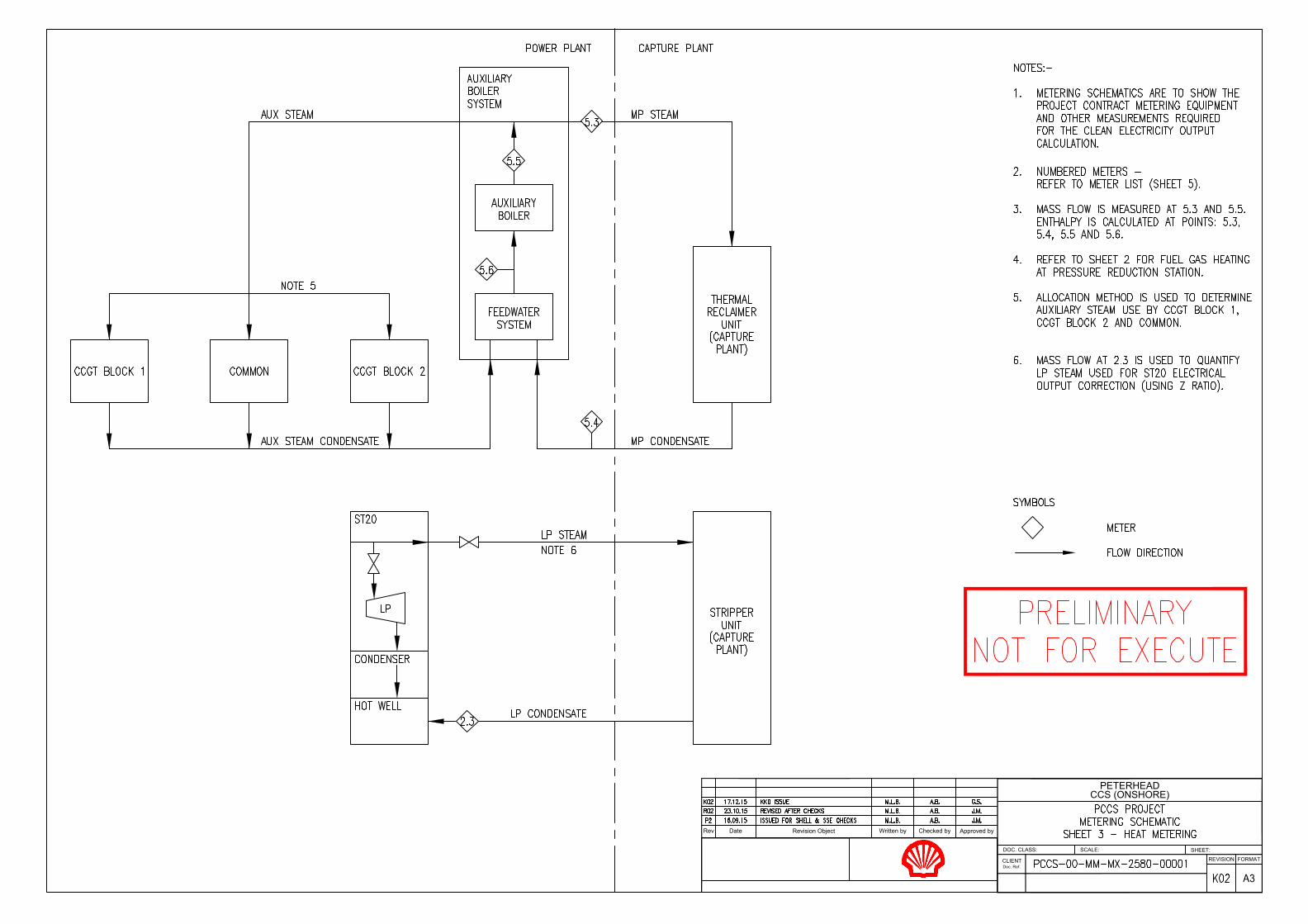
Rev Written by Checked by Approved byRevision ObjectDate
SHEET:
FORMAT
DOC. CLASS:
REVISION
SCALE:
CCS (ONSHORE)
CLIENT
Doc. Ref.
PETERHEAD

Rev Written by Checked by Approved byRevision ObjectDate
SHEET:
FORMAT
DOC. CLASS:
REVISION
SCALE:
CCS (ONSHORE)
CLIENT
Doc. Ref.
PETERHEAD

Rev Written by Checked by Approved byRevision ObjectDate
SHEET:
FORMAT
DOC. CLASS:
REVISION
SCALE:
CCS
CLIENT
Doc. Ref.
PETERHEAD

PETERHEAD CCS PROJECT CEO Calculation Metering Data Acquisition
APPENDIX 3. CEO Calculation Metering Data Acquisition The proposed CEO metering data acquisition architecture is depicted in Figure A-1 below:
Figure A-1: Proposed Clean Electricity Metering Data Acquisition Architecture
Note: Offsite indicates functions that are located remote to the Project sites
Doc. no.: PCCS-00-PTD-IN-5520-00002, Surveillance, Metering Allocation Strategy and Design Package, Revision: K03 The information contained on this page is subject to the disclosure on the front page of this document. 40