Embed Size (px)
Citation preview

Personal handbook for
ELASTOPIPE Deluge System
This handbook is for internal use in Trelleborg Offshore only!
Owner of book:
……………………………………………………………………………..
Date received:………………………….
This edition of Personal Handbook on the System was completed from the publisher June 2011.
A publication from www.indok.no, Kongsberg, Norway.
All rights reserved. Reproduction of this publication entirely or in parts are not allowed without the written permission of Trelleborg Offshore.

1

2
Contents
1 INTRODUCTION 41.1 Purpose Of Manual 4
2 GENERAL INFORMATION 52.1 Symbols And Conventions 5
3 TECHNICAL DESCRIPTION 63.1 6
4 TRANSPORT AND HANDLING 84.1 Transport 84.2 Handling 94.2.1 Lifting Vertically Positioned Pipes 10
5 PREPARATION AND INSTALLATION 115.1 Work Process 115.1.1 Unpacking and preparation 125.2 Support 135.2.1 Definitions 135.2.2 Design Criteria 145.2.3 Fastening to Structure 165.2.4 Primary Support 175.2.4.1 Design Models for UNO-profiles 175.2.5 Secondary Support 185.3 INSTALLING 225.3.1 Cutting 225.3.1.1 Cutting using an air driven, slow moving band
saw with water flushing 225.3.1.2 Cutting using Tiger saw/Bayonet saw 235.3.1.3 Cutting using a hacksaw 235.3.2 Jointing 245.3.2.1 Preparation of passive Fire Protection for joints 245.3.2.2 Installing Pipe Fittings 255.3.2.3 Fitting a nozzle clamp on 315.3.2.4 Operating the Band-It Machine 335.3.2.5 Mounting ConNect Clamps 365.3.2.6 Heat Tracing 385.3.4 Mounting 39
3
5.4 Checking 405.4.1 Pressure Testing 405.4.2 Full scale function testing 40
6 MAINTENANCE, REPAIRS AND MODIFICATION 41
7 SUPPORT DEFINITIONS 427.1 Tables for 0.5 Barg Dynamic Explosion Load 427.1.1 Table of Max Span 427.1.2 Explosion Load on 43

4
1 INTRODUCTION
1.1 Purpose Of Manual
The purpose of this handbook is to provide installation guidance for the System, as supplied by Trelleborg Offshore.
The handbook is intended to give the user sufficient technical information and data to be able to understand the functions and features of the System, together with the necessary transport, handling, commissioning, main-tenance and installation information.

5
2 GENERAL INFORMATION
2.1 Symbols and Conventions
The following words and symbols found throughout this manual mark special messages to alert the operator of specific information concerning of thePERSONNEL, the EQUIPMENT or the PROCESS.
The WARNING symbol draws attention to potential danger for personnel(including possible loss of life) and considerable damage to equipment
The CAUTION symbol draws attention to potential danger of damage to equipment
The NOTE symbol draws attention to additional clarifying infor mation or special instructions which are also crucial for equipment or to the instal lation performed.
The QUALITY symbol draws attention to operations where quality inspections must be performed
2.2 Safety Notes
The WARNING symbol as a Safety Note draws attention to installer’s responsibility to identify any possible danger and take necessary precautions to avoid serious personal injury or equipment damage.
2.3 Abbreviations
Abbreviation Explanation mm millimetres " inches kg kilogram TM Trade Mark

6
3 TECHNICAL DESCRIPTION
3.1
is made of synthetic rubber and replaces rigid steel, titanium and glass-fibre reinforced plastic piping.All sleeves and tees for extensions are supplied in titanium.
is a flexible piping system, which is easy and safe to fit, and has the following unique properties:
• No corrosion• Jet fire resistant• Impact resistant• Minimizes water hammer effects• Explosion resistant• Frost resistant• Maintenance free• No welding or hot work necessary
These properties make ideal for the piping of deluge and sprinkler systems for offshore oil and gas installations, ships, industrial plants, buildings, mines, etc.
There are different ways to support
• UNO Channels• Cable trays• Duo Clamps (when using existing pipes for support)
is a unique piping system and can therefore be put into use in a variety of unconventional surroundings where flexibility is necessary.
The system has many unique joint and connection solutions. Examples of an system with joints and connections are shown on the following page.
For detailed technical data, see the System Manual

7
End Cap
End Cap
Support
Reducing or straight Tee
Flange Connection
Commonly used Fittings and Couplings
Straight Connectionwith Band-It(shown enlarged without fire protection)
Straight Connector with Nozzle Adapter
2”
Reduced or straightX-Connector
2” Pipe
Nozzle Adaptor(shown enlarged without fire protection)
End Connection with Nozzle adapter and inspection Plug
1” Pipe
4” Pipe
6” Pipe

8
4 TRANSPORT AND HANDLING
4.1 Transport
All titanium parts must be stored dry and NOT together with other materials
can be bent to 5D, but avoid breaking and buckling
Preassembled
are transported and stored in baskets.
Fittings and mounting materials are transported and stored on pallets.
The protection on preassembled fittings should be kept on dur-ing all transport and handling.

9
4.2 Handling
All lifting operations shall be done according to local lifting procedures, surveyed by certifiedoperators
Both single pipes and bundles of pipes can be lifted positioned horizontally using soft slings.
Maximum distance between soft slings are 3 metres.

10
4.2.1 Lifting vertically positioned Pipes
Straps in the end of pipes can lift both single and bundles of pre-assembledpipes positioned vertically.
During lifting of vertically positioned pipes, the strap must be secured by lashing the strap around the pipes twice, and with double strapping.

11
5 PREPARATION AND INSTALLATION OF
5.1 Work Process
1. Briefing installation crew in actual project
2. Supporting methods, Chapter 5.2
3. Cutting , Chapter 5.3.1
4. Applying sealant, Chapter 5.3.2
5. Preparation of passive fire protection, Chapter 5.3.3.1
6. Installation of pipe fittings, Chapter 5.3.3.2
7. Installing Band-It bands, Chapter 5.3.3.5
8. Control Chapter 5.3.3.5
9. Mounting ConNect Clamps Chapter 5.3.3.6
10. Installation of nozzle clamps, Chapter 5.3.3.3
11. Fitting ends to , Chapter 5.3.3.4
12. Mounting , Chapter 5.3.4

12
5.1.1 Unpacking and preparation
This section provides guidelines for unpacking and preparation of once it has arrived at the installation site.
The following instructions apply when is removed from its storage and transportation protection:
If possible, keep in its packed condition prior to installation.
Packaging material is the customer’s property and should be disposed of in an environmentally safe manner.
1. Remove the packing that covers .
The pipes are stable so there is no danger of uncontrolled movement during removal of packing materials.
2. Remove packing material from installation parts and tools.
Make sure that the content of the package tally with the packing list, which is included.
Conduct a thorough visual inspection of every component and tool. Be particularly aware of loose or broken components. Make sure that mechanical/electrical tools function as expected. Report any damage or discrepancies, enclosing a copy of the packing list.
is made of flexible composite materials and can be installed in a different manner than other conventional piping systems.The pipes are not subject to thermal expansion so expansion loops are not necessary.
13
5.2 Support
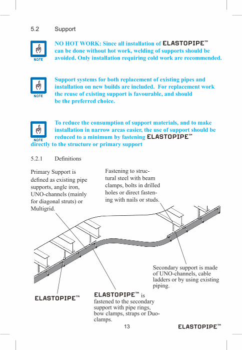
NO HOT WORK: Since all installation of can be done without hot work, welding of supports should be avoided. Only installation requiring cold work are recommended.
Support systems for both replacement of existing pipes and installation on new builds are included. For replacement work the reuse of existing support is favourable, and should be the preferred choice.
To reduce the consumption of support materials, and to make installation in narrow areas easier, the use of support should be reduced to a minimum by fastening directly to the structure or primary support
5.2.1 Definitions
Primary Support is defined as existing pipe supports, angle iron, UNO-channels (mainly for diagonal struts) or Multigrid.
Fastening to struc-tural steel with beam clamps, bolts in drilled holes or direct fasten-ing with nails or studs.
is fastened to the secondary support with pipe rings, bow clamps, straps or Duo-clamps.
Secondary support is made of UNO-channels, cable ladders or by using existing piping.

14
5.2.2 Design Criteria
isflexibleandtheelasticmaterialdampensthe effect of explosion, impacts and water hammer. The support should be designed to allow the dampening, but also to allow draining and avoid sagging.
In most cases explosion (transient) is the dimensioning load in support calculation. A typical Design Accidental Load (DAL) of 0,25 bar is normally dominating compared to the load contributions from weight, wind and water hammer.
Normally the weight of and support only
contribute to the dimensioningof the support when the pipes are filled with water.
An installation shall have a nice, robust appearance without sagging and water pockets. The principle of free hanging pipe with minimum support to allow dampening often contradicts this.
Water hammer effects (transient) can be damaging to pipes and support, but are dampened considerably by
.The loads from water hammer effects are only considered in specific project and design cases.
Wind loads are normally negligible.
h
L1
L2
F1
F2
F3
15
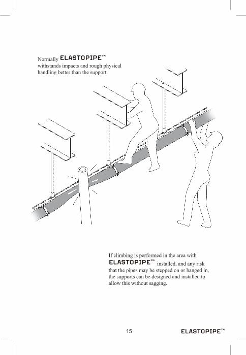
If climbing is performed in the area with installed, and any risk
that the pipes may be stepped on or hanged in, the supports can be designed and installed to allow this without sagging.
Normally withstands impacts and rough physical handling better than the support.

16
5.2.3 Fastening to Structure
All installation of can be made without hot work. Fastening methods which do not include welding or other hot work are recommended.
Using bolts are thecommon way to fasten
supports.Bolts should alwaysbe secured.
Supports can also befastened directly tostructure with nailsor studs.
Fastening should alwaysbe made according tolocal requirements.
Fastening with beam clamps.
Beam clamps mustalways be secured against sliding and twisting by use ofdouble bolts andclamps on both sides.

17
5.2.4 Primary Support
Traditional pipe supports made of angle iron are suitable as primary support for , but stainless systems (e.g. UNO channels) with standard prefabricated components are available and recommended.
In replacement projects it is recommended to use the existing support and bolt holes.
5.2.3.1 Design Models for UNO-profiles
● Fixed - Fixed
● Fixed - Hinged
● Hinged - Hinged
● Fixed - Free (Cantilever)
The distance between primary supports is depending on explosion loads. Ref. Chapter 7.

18
5.2.4 Primary Support, continued In order to compile the primary support the designer has to select the load from the secondary support onto the primary support, called Fx. The force ( e.g. F1, F2, and F3 in 5.2.2) is either 2145 kg (single UNO profile)or 3831 kg (double UNO profile).Then measure the height (h) from existing structural steel down tocentre of .
The brackets can be used in the following configurations:
Table 5.1 Support Bracket DesignsHeight (h) of
primary support:(cantilever)
Load (Fx) on primary support (kg)
500 600 750 1000 1200 1500 3200
0-0.4 m K10-400-P
SS
0-0.4 m K10-400-P SS
0-0.67 m K20-600-P SS
0-0.67 m 2 x K20-600-P SS
0-0.93 m MG CH 100-3SS
0-0.93 m 2 x MG CH 100-3SS
0-3.0 mCompiled frame of UNO Channels
To be designed and verified from case to case

19
5.2.6 Secondary Support
Max 100 mm
Locking nut
The clamp bolts must be secured with lock nuts.
Do not tighten the clamp bolts more than necessary to obtain a firm grip around the pipe without deforming, and leaving a gap between the two clamp halves.
For self draining, always mount pipes sloping (2%).

20
5.2.5 Secondary Support, continued
When ladders are used as secondary support, and the explosion load is the dimensioning force, pipe clamps are used for every 4th stage.
Ladders are fastened with bracketsfor every 3rd meter.
When the dimensioning force is stronger than the explosion load, i.e. loads from water hammer, clamps on every second stage of the ladder is recommended.
Around corners max distance between clamps should not exceed 1300 mm.
Do not tighten the clamp bolts more than necessary to obtain a firm grip around the pipe without deforming, and leaving a gap between the two clamp halves.

21
Typical use of cable ladders for support of piping.
In replacement projects the existing pipe can be used as secondary support, and fastened with Duo-clamps.
Existing cable ladders are suitable for support of piping.

22
5.3 Installing
5.3.1 Cutting
Protective wear must be worn and safety precautions observed, asdefinedbythemanufacturerofthecuttingtool. Some of the methods shown below may require “Hot Work” permits.
Afine-toothedbladeisalwaysrecommendedforacleancut.
5.3.1.1 Cutting using an air driven, slow moving band saw with water flushing
This method entails no risk of sparks.
23
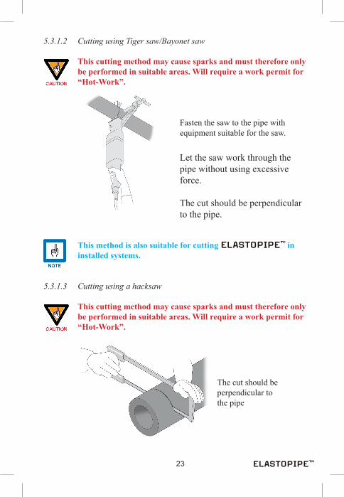
5.3.1.2 Cutting using Tiger saw/Bayonet saw
This cutting method may cause sparks and must therefore only be performed in suitable areas. Will require a work permit for “Hot-Work”.
Fasten the saw to the pipe with equipment suitable for the saw.
Let the saw work through the pipe without using excessive force.
The cut should be perpendicular to the pipe.
This method is also suitable for cutting in installed systems.
5.3.1.3 Cutting using a hacksaw
This cutting method may cause sparks and must therefore only be performed in suitable areas. Will require a work permit for “Hot-Work”.
The cut should be perpendicular to the pipe

24
5.3.2 Jointing
Equipment required: • Pipe fitting • Band-It band (quantity in accordance with the Band-It chart) • Sealant (Superfix and fire sealant) • Band-It machine • Chain block • Rubber mallet / fibre mallet
5.3.2.1 Preparation of passive Fire Protection for joints
All Fire protection material and clamps must be slided onto each pipe end before it is assembled with the fitting.
Band-It clamps for the fire protection material
If the is used inclassified areas, all joints must be fire protected. The fire protection material and clamps must be slided over one end of the pipe before the other end is assembled onto the joint connection.

25
5.3.2.2 Installing Pipe Fittings
For cutting , see chapter 5.4.1.
Use a chain block and slings to ease the installation of fittingsinto pipes.
Position the fitting into the pipe against the stop marking.
Ifitisdifficulttoinsertthefittingusearubbermalletorsimilar
whichwillnotdamagethefitting.
Do not use metal tools.

26
5.3.2.2 Installing Pipe Fittings, continued
SlideBand-Itbandsincorrectnumberandsuitabledimension according to the chart below onto the pipes.
Inspect and remove loose objects
Inspect the pipe fitting visually for damages or other defects
Mark the pipe for correct position-ing of Band-It bands and tighten in order 1 - 2
1 2

27
Table 5.2 Band-It Specifications
dimensionOutsidediameter
No. of Band-It
bands per end
Type Band-It band
ID 25 1” 53 mm 2 ULC, 0,030”X3”
ID 40 1 ½” 68 mm 2 ULC, 0,030”X3”
ID 50 2” 78 mm 2 ULC, 0,030”X31/2”
ID 75* 3” 103.5 mm 3 ULC, 0,030”X41/2”
ID 100* 4” 128.5 mm
ID 150* 6” 184 mm
ID 200* 8” 234 mm
All dimensions use Band-It lock type INCONEL 625
* Dimensions marked in “italic” normally are secured with ConNect clamps not Band-It, refer to 5.3.2.5

28
5.3.2.2 Installing Pipe Fittings, continued
Insert the connector into the first pipe, check for correct location.Likewise insert rest of pipes.
Apply sealant according to Chapter 5.4.2
Apply Superfix sealant evenly to the end surfaces with the aid of a putty knife or similar. This is made easier if the tool is coated with dishwashing soap before use.
29
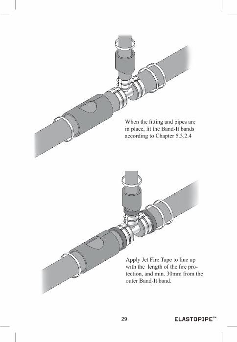
When the fitting and pipes are in place, fit the Band-It bands according to Chapter 5.3.2.4
Apply Jet Fire Tape to line up with the length of the fire pro-tection, and min. 30mm from the outer Band-It band.

30
5.3.2.2 Installing Pipe Fittings, continued
Fit the Tee Fire Protection and secure with Band-It. Pry open and slide the in-line Fire Protection in position around the Tee.The split in the In-line Protection must be covered with a piece of Band-It band, secured with clamps.
Applyfiresealanttoalljoints

31
5.3.2.3 Fitting a nozzle clamp on
Equipment required: • Cutting tool • Nozzle clamp • Loctite thread lock • Band-It bands (quantity according to the Band-It chart) • “Superfix” sealant (in the hole) • Band-It machine UL 9000
Place the two halves of the nozzle in the desired position and secure it with Band-It bands.
Enter the cutting tool in the threaded opening and drill a hole in the pipe. The cutting tool is designed to cut only as far into the pipe as is necessary.
¾″Band-It
32
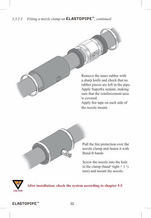
5.3.2.3 Fitting a nozzle clamp on , continued
Remove the inner rubber with a sharp knife and check that no rubber pieces are left in the pipe. Apply Superfix sealant, making sure that the reinforcement area is covered.Apply fire tape on each side of the nozzle mount.
Pull the fire protection over the nozzle clamp and fasten it with Band-It bands
Screw the nozzle into the hole in the clamp (hand¬tight + 1 ½ turn) and mount the nozzle.
After installation, check the system according to chapter 5.5
33
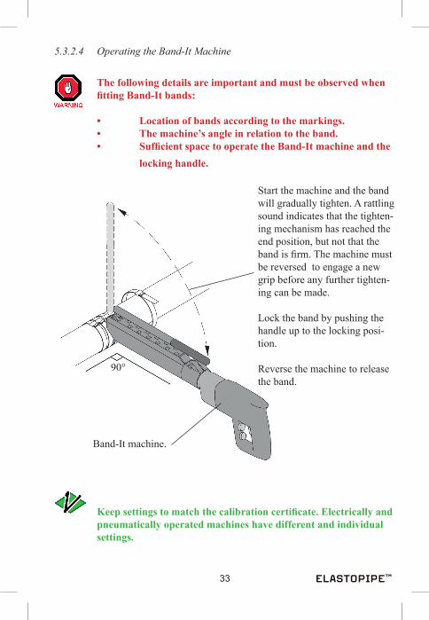
5.3.2.4 Operating the Band-It Machine
The following details are important and must be observed when fittingBand-Itbands:
• Locationofbandsaccordingtothemarkings. • Themachine’sangleinrelationtotheband. • SufficientspacetooperatetheBand-Itmachineandthe locking handle.
Start the machine and the band will gradually tighten. A rattling sound indicates that the tighten-ing mechanism has reached the end position, but not that the band is firm. The machine must be reversed to engage a new grip before any further tighten-ing can be made.
Lock the band by pushing the handle up to the locking posi-tion.
Reverse the machine to release the band.
90°
Band-It machine.
Keepsettingstomatchthecalibrationcertificate.Electricallyand pneumatically operated machines have different and individual settings.

34
5.3.2.4 Operating the Band-It Machine, continued
Please note the following when using pneumatically operated Band-Itmachine:
• Daily lubrication of the tool is necessary. Lubricate the thightening screw with molybdenum grease.• Run the machine until it stops completely. Then release the clamp and repeat the process, making sure the clamp is tight.• Trelleborg Viking must carry out all repair and calibration onshore.
Use of the pneumatic Band-It machine:
• Apply a few drops of oil in the pneumatic tool (via the air connector).• The machine must only be used with an approved air regulator.• The pressure setting must be set according to the machine’s calibration certificate.Check the airpressure each time the machine is connected to compressed air.
Tightening Screw
Air Connector

35
Bend excessive end up and down until it breaks off
AcorrectlyfittedBand-Itshouldlookasillustratedbelow.The band must follow the contour the lock, and must not slide back more than 1mm
Tap the buckle down with a hammer to complete the lock
CORRECT WRONG
If the band is not correctly fitted, it must be refitted with a new

36
5.3.2.5 Mounting ConNect Clamps
Equipment required: • Pipe Fitting • ConNect Clamps • Sealant (Superfix and fire sealant) • Molycoat • Torque Wrench
Fire Protection SleeveConNect Clamp
Inboard BoltOutboard Bolt
Strap
Pipe Fitting
Rod
Strap
Installation sequence:
1. Slide the fire protection sleeve and the ConNect clamp onto the before the fitting is inserted.
2. Insert the fitting into the by hand, and push until the pipe contacts the stop ring on the fitting.
3. Lubricate the bolts and tighten sequencially to obtain a snug fit. The rods should be parallel, and the gaps should be equal on both sides, check by measuring.
4. Position the clamp.

37
Strap
Fire Protection Sleeve
ConNect Clamps
5. Tighten the bolts sequencially to 50 % of the labeled torque. Each bolt maximum 2 turns at a time,using a torque wrench.
6. Tighten the inboard bolts to full labeled torque. Tighten the outboard bolts likewise.
7. Slide the second ConNect clamp onto the other before it is mounted onto the fitting.
8. Position the second clamp in line with the first one, and repeat the steps 3 - 6.
9. Slide the fire protection sleeve over the clamps, fasten with straps and seal the exposed gaps with fire sealant compound.

38
5.3.2.6 Heat Tracing
1. In the heat tracing cable is drawn inside the pipe, exposed to the medium.
Max. 15 m Max. 15 m
Heat tracing Cable
Sealing kit
2. A flag line should be pulled through the pipe before connecting pipe and fittings to help installing the heat tracing cable. Lubricate cable with soap before installation. The cable must be pulled carefully from reel by two persons. Termination seals are supplied in plastic bags together with a mounting instruction that should be followed thoroughly. The seal must be tightened firmly, without squeezing the teflon.
3. Install fire protection according to chapter 5.3.2.1

39
5.3.4 Mounting
Secure pipe and tighten the end clamps.
When appropriate support is installed, place pipe clamps with max. spacing of 1.3m (tighten to avoid sagging).
Use a chain hoist and “soft-sling” to lift and support the pipe during installation.
Minimum bend radius for is 5D
See Table next page

40
Table 5.3 Dimensions
Tubing Dimension D Bending Radius Weight1” (ND25) 53 mm 265 mm 2,8 kg/m
1 1/2” (ND40) 68 mm 340 mm 3,5 kg/m2” (ND50) 78 mm 390 mm 4,4 kg/m3” (ND75) 103,5 mm 518 mm 6,6 kg/m4” (ND100) 128,5 mm 643 mm 8,4 kg/m6” (ND150) 184 mm 920 mm 15,0 kg/m8” (ND200) 234 mm 1170 mm 20,0 kg/m
5.4 Checking
When the installation of the system is completed,andbeforeanymountingoffireprotection, allsupports,clampsandBand-Itbands(locks,positionand quantity) must be inspected by a Trelleborg Offshore supervisor.
Use a check list for the inspection.
Flushing, pressure testing and full scale testing may be required and faults must be rectified after the installation and testing procedure is completed.
Each system/project will require a unique set of tests.
5.4.1 Pressure Testing
5.4.2 Full scale function testing

41
6 MAINTENANCE, REPAIRS AND MODIFICATION
has an expected life time of more than 30 years without maintenance, but inspection of joints, nozzles, and end caps, etc. should be performed at regular intervals according to TV inspection procedure TV 89104-005.
is well suited for modification as it is an easy system to expand. Minor damages (< 4 cm² ) on the pipe surface can be repaired by applying a fire protection section over the damaged area.
Damages to larger areas of pipe are replaced by cutting out the damaged section and replacing it by jointing in a new section.

42
7 SUPPORT DEFINITIONS
7.1 Tables for 0,5 Barg Dynamic Explosion Load
7.1.1 Table of Max Span
Pipe dimension1”
N
D25
1,5”
N
D40
2”
ND
50
3”
ND
75
4”
ND
100
6”
ND
150
8”
ND
200
Single UNO(Span mm)
Fixed -Fixed
4600 4000 3700 3000 2600
Hinged -Fixed
2700 2300 2100 1800 1500
Hinged -Hinged
1500 1300 1200 1000 800
Fixed -Free
(cantilever)
300 300 300 200 200
Double UNO(Span mm)
Fixed -Fixed
5700 5100 4800 4100 3600 3000 2600
Hinged -Fixed
3300 3000 2400 2400 2100 1800 1500
Hinged -Hinged
1900 1700 1300 1200 1200 1000 800
Fixed -Free
(cantilever)
400 400 300 300 300 200 200

43
7.1.2 Explosion Load on
Pipe dimension
1”(N
D25
)
1,5”
(ND
40)
2”(N
D50
)
3”(N
D75
)
4”(N
D10
0)
6”(N
D15
0)
8”(N
D20
0)
Max span, second-ary
support, Single UNO (mm)
4600 4000 3700 3000 2600 - - - -
Explosion load/meter
Single UNO (kg)
267 310 339 411 482 - - - -
Max load on one span
Single UNO (kg)
1230 1240 1253 1233 1254 - - - -
Max span, second-ary
support, Double UNO (mm)
5700 5100 4800 4100 3600 3000 2600
Explosion load/meter
Double UNO (kg)
384 427 455 528 599 757 899
Max load on one span
Double UNO (kg)
2189 2176 2185 2164 2156 2270 2337
Conclusion:
When using single UNO as secondary support the load onto the primary support is less than 1300 kg.
When using double UNO as secondary support the load onto the primary sup-port is less than 2350 kg.

44


Trelleborg OffshoreP. O.Box A
N-3051 MjøndalenNorway
Tel.: +47 32 23 20 00Fax: +47 32 23 22 00
Email: [email protected]
www.trelleborg.com/offshore/no
www.elastopipe.com
Production: Industriell Dokumentasjon a.s - www.indok.no