Embed Size (px)
Citation preview

1

Submitted to “Software – Practice and Experience”
Persistent Objects in Procol –Illustrated with a GIS case
Peter van Oosteromy, Chris Laffraz and Vincent Schenkelaarsz
y TNO Physics and Electronics LaboratoryP.O. Box 96864, The Hague, The Netherlands
Email: [email protected]
z Software Engineering Research CenterP.O. Box 424, Utrecht, The Netherlands
Email: flaffra, [email protected]
Persistent objects are objects whose contents may outlive the execution time of the pro-gram. This paper describes the process of introducing persistent objects in the object-oriented programming language Procol. The strength of persistent objects in an object-oriented programming language is the integration of a database system with a pro-gramming language. Persistent objects make the program development easier, becausethe programmer does not have to implement the explicit loading and saving of data.Besides the general functional aspects, special attention is paid to graphic applicationsin order to deal with their specific geometric requirements. For example, it must be pos-sible to find, in an efficient manner, all graphic objects that fall within a given region.These issues, persistent objects and their geometric requirements, have not yet got theattention they deserve in the literature covering object-oriented graphic systems wheremodeling and functional aspects dominate. The concepts are illustrated with a case fromclass of systems which may be considered as typical for non-traditional applications; aGeographic Information System.
Keywords: OO, persistence, GIS, language design.
2

Introduction
The fact that the object-oriented approach is so successful in computer graphics, is mainlydue to the system modeling capabilities that the object-oriented paradigm offers. The spe-cialization relationships which exist between the graphic objects in a system, can be modeledwith inheritance or delegation which are present in many object-oriented development envi-ronments. Geometric data types, such as points, vectors and matrices may be implementedby abstract data types using object classes [9, 15, 16, 34]. However, in practice this modelingpower is not enough when implementing CAD systems or Geographic Information Systems(GISs) which deal with large data sets. Integrated database facilities are required to supportthe graphic application in an efficient manner.
In this paper we describe a solution that is based on the introduction of persistent objects inthe object-oriented programming language called Procol. A detailed functional description ofthe C–based language Procol can be found in [49] and some implementation aspects in [50].The resulting system is also extendable with new (persistent) types and operators. In itselfthis approach is not new and has been described by several other authors [2, 40, 45], but wealso tried to make the system suitable for highly interactive and graphic applications. Thisgoal is achieved by putting emphasis on both time-efficiency (offering techniques such as:navigation, index structures, and parallelism) and the recognition of multi-dimensional data.As an example, not only one dimensional, but also multi-dimensional index structures areprovided in Procol. The emphasis in this document is on the inclusion of persistent graphicobjects in the syntax and semantics of Procol and on the implications thereof for the technicalrealization, e.g., how Procol deals with problems such as referential integrity and associativesearching.
We will state the problem area in section “The Need for Persistence.” The alternative ofusing a persistent programming language is described in section “DBMS based GIS Architec-tures.” three different architectures are described. We define our general requirements forpersistence in an object-oriented language in section “Our Wish List.”
Our first attempt to introduce persistence in Procol and comparisons with several other sys-tems are described in section “The First Attempt.” Building on this experience the followingtopics are discussed in more detail: referential integrity, (multi-dimensional) search problems,Procol extension alternatives and object instances of different sizes in sections “ReferentialIntegrity” through “Object Instances of Different Sizes,” respectively. In section “PersistentObjects in Procol” we present the solution as chosen in Procol. In nearly all the sectionsthe requirements of graphics play an important role. The discussions are illustrated withexamples based on graphic systems. In section “The GIS case example,” the use of persistentProcol is illustrated with a GIS case. Finally, section “Further Research” indicates some topicswhere further research is required.
The Need for Persistence
The computer science research in the area of programming languages emphasizes program-ming constructs and data structures. One of the most popular paradigms is that of AbstractData Types (ADTs). Object-Oriented Programming Languages (OOPLs) encapsulate thisparadigm in an elegant manner using object types to describe the ADTs. Access from outsideto the data inside an object instance1 is only possible through the methods or proceduresdefined for that object type.
1In this document we will use the term object type to indicate a class of objects and the term object to indicate oneinstance. In case more emphasis is needed we use the term object instance explicitly.
3
The data stored in data structures (or objects) of a running program are in general volatile,that is, as soon as the program stops, the data are lost. However, in many applications thedata itself are very important. An obvious solution is to save the data in a file by explicitwrite statements. The next time the program is started it first reads the data from file intothe volatile data structures. Persistent objects make the program development more efficient,because the programmer does not have to worry about the reading and writing of data fromand to disk. Also, the structure of the data file may become quite complex, resulting inpossibly intricate parsing. Moreover, for large quantities of data this “file” solution becomescumbersome during the execution of the program. Consider as an example an informationsystem that registers bank accounts. A characteristic of this and many other informationsystems is that the objects are well structured, quite passive and occur in large quantities.Passive objects are objects that hardly ever send messages to other objects (except for replies);they only react to messages from outside. In the bank account example, an account objectreplies its current amount when asked for, and updates it when told so by a message from anauthorized object.
Database Management Systems (DBMS) have been developed to deal with the large amountsof data mentioned above. DBMSs concentrate on the information representation and tacklerelated problems such as, integrity, security, redundancy, consistency, efficient searching,query formulation and concurrency control. A major drawback is that the DBMSs of thecurrent generation are not extendable with new data types and operators. This makes theuse of these DBMSs inconvenient in non-traditional applications that need support for otherdata types.
The database research community has recognized this deficiency and is now trying to designsystems that are more open [17, 44, 62]. At the other side the OOPL research communityhas recognized the need for persistent objects. Now, these two worlds meet. In some casesthese encounters result in conflicts because of very different and incompatible principles.For example, explicit (navigation) links amongst instances are considered harmful by thedatabase community, because they are hard to maintain. However, these same links formthe backbone in representing complex objects in OOPLs. On the other hand, sometimes thecombination of the two research communities results in a nice symbiosis. An example of thisis that the concurrency control problem in the database is solved by the model of an objectthat accepts messages one by one (as in Procol).
We are interested in interactive graphic applications, such as: CAD systems, VLSI Design,and GISs, see Figure 1. Common aspects in these systems are: interactivity, graphics, andlarge amounts of data. In [56] we showed that the object-oriented approach offers a gooddata modeling and design environment for GIS applications. In the same paper the need forpersistent objects in our object-oriented programming language Procol, was identified.
DBMS based GIS Architectures
GISs have a clear need for persistent data storage. An alternative for using a persistentprogramming language to implement a GIS is using a (normal or volatile) programminglanguage together with a database management system. Most commercial GISs are basedon a DBMS, which is in most cases a relational database, such as Oracle, or Ingres [46].One obvious drawback of the standard DBMSs is that they can not manipulate geographic2
data. That is, there are no geometric attribute types (point, polylines, polygons) and operators(distance, intersection, circumference, area). Therefore, it is impossible to store geographicdata in a natural manner and to pose queries such as: “Select all municipalities with more
2The geographic entities or objects in a GIS are based on two different types of data: spatial and alphanumericthematic data. In turn, spatial data have two components: geometric and topological data [53].
4

Figure 1: A Geographic Information System
5

DMBSRelational
Unique id’sStorage systemGeometric
Geographic Information System
Figure 2: The Dual GIS Architecture
that 10,000 inhabitants and located within 3 kilometers from a lake.” Further, these systemslack multi-dimensional access methods (or index mechanisms), which are obviously requiredas the size of geographic data sets is very large.
Different DBMS-based solutions have been suggested and implemented in order to overcomethese problems. Three different types of system architectures can be distinguished: dual ar-chitecture, layered architecture, and integrated architecture. The term dual architecture wasfirst introduced in [58]3. In the next subsections, the pros and cons of these architectures arediscussed. Note that it is not always easy to classify a specific system. For example Small-world GIS [11] possesses characteristics of both the layered and the integrated architecture.
Dual Architecture
The most common type of commercial GIS architecture is the dual one. Dual architectureGISs have a separate subsystem for storing and retrieving spatial data, whilst thematicinformation is stored in a relational DBMS. This dual architecture is not conceptually elegantand also reduces the performance. An object that has both a thematic and a spatial component,has parts in both subsystems that are linked by a common identifier. In order to retrieve anobject, the two subsystems have to be queried and the answer has to be composed. Figure 2illustrates this dual GIS architecture. Typical examples of GISs with dual architecture are:ARC/INFO [19, 35] from ESRI, MGE [29] from Intergraph, SICAD [42, 43] from Siemens, andARGIS 4GE [48] from Unisys.
The advantage of the dual architecture is that it is partly based on a standard DBMS andthat the storage and retrieval of spatial data can be efficient. However, this method has somesevere drawbacks. The existence of two storage subsystems implies that query optimizationis not possible to the full extent. A relational DBMS offers transactions that are atomic,durable, and serializable. Storing data outside the relational DBMS can result in losingthe transaction semantics, because the two storage managers each have their own lockingprotocol. The final drawback of the dual architecture is that integrity constraints can beviolated. For example, an entity can still exist in the spatial storage subsystem while it hasbeen deleted from the relational DBMS.
3A similar classification was described by Bennis et al. in [6, 7]. They used the terms partial DBMS architecture,shell architecture, and full DBMS architecture for respectively dual architecture, layered architecture, and integratedarchitecture.
6
Geographic Information System
Standard Relational DBMS
Spatial Support Layer
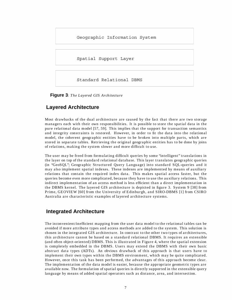
Figure 3: The Layered GIS Architecture
Layered Architecture
Most drawbacks of the dual architecture are caused by the fact that there are two storagemanagers each with their own responsibilities. It is possible to store the spatial data in thepure relational data model [57, 59]. This implies that the support for transaction semanticsand integrity constraints is restored. However, in order to fit the data into the relationalmodel, the coherent geographic entities have to be broken into multiple parts, which arestored in separate tables. Retrieving the original geographic entities has to be done by joinsof relations, making the system slower and more difficult to use.
The user may be freed from formulating difficult queries by some “intelligent” translations inthe layer on top of the standard relational database. This layer translates geographic queries(in “GeoSQL”; Geographic Structured Query Language) into standard SQL-queries and itmay also implement spatial indexes. These indexes are implemented by means of auxiliaryrelations that contain the required index data. This makes spatial access faster, but thequeries become even more complicated, because they have to use the auxiliary relations. Thisindirect implementation of an access method is less efficient than a direct implementation inthe DBMS kernel. The layered GIS architecture is depicted in figure 3. System 9 [38] fromPrime, GEOVIEW [60] from the University of Edinburgh, and SIRO-DBMS [1] from CSIROAustralia are characteristic examples of layered architecture systems.
Integrated Architecture
The inconvenient/inefficient mapping from the user data model to the relational tables can beavoided if more attribute types and access methods are added to the system. This solution ischosen in the integrated GIS architecture. In contrast to the other two types of architectures,this architecture cannot be based on a standard relational DBMS. It requires an extensible(and often object-oriented) DBMS. This is illustrated in Figure 4, where the spatial extensionis completely embedded in the DBMS. Users may extend the DBMS with their own basicabstract data types (ADTs). An obvious drawback of this approach is that users have toimplement their own types within the DBMS environment, which may be quite complicated.However, once this task has been performed, the advantages of this approach become clear.The implementation of the data model is easier, because the appropriate geometric types areavailable now. The formulation of spatial queries is directly supported in the extensible querylanguage by means of added spatial operators such as distance, area, and intersection.
7

Geographic Information System
Handling ofSpatial DataExtendable DBMS
Figure 4: The Integrated GIS Architecture
Perhaps the most important advantage is the good performance of these systems. The directimplementation of data types in the kernel of the DBMS is very efficient. Another facilitysupporting system performance, is that one may provide own spatial access methods. Thedevelopment of integrated GIS architectures depends on the availability of open DBMSs. Afew characteristic examples of integrated GIS architectures are the research oriented systemsGeoTropics [7] from the University of Paris VI and IGN France, TIGRIS [26] from Intergraph,and GEO system [58] from TNO The Netherlands. The latter is based on the open DBMSPostgres [44].
Our Wish List
The DBMS based solutions of Section “DBMS based GIS Architectures” all have in commonthat data must be transported from the DBMS to the application program and back if thechanges of new data have to be stored permanently. As explained in the introduction, thesetransfers are a significant portion of the application implementation effort. Persistent pro-gramming languages try to remove this part of the implementation from the application.This section shortly discusses the major requirements for persistent objects in Procol. Somewill be elaborated in one of the later sections, in which case the section referred to will bementioned here. Note that these requirements may neither be orthogonal nor independent ofeach other.
r1 Upward compatible. Persistent objects have to be introduced with a minimal change toProcol. This implies that existing Procol programs do not have to be changed in orderto be compiled by the new version of the Procol compiler.
r2 Transparent persistent objects. Persistent objects are treated by the application in thesame manner as volatile objects. An exception may have to be made for incompatibledatabase facilities, e.g., associative searching, that is object searching based on thecontents or value of instances. Atkinson et al.[3] refine this by recognizing the followingprinciples for persistent data (they assume several levels of persistence):
1. Persistence independence: the persistence of an object is independent of how theprogram manipulates that object. So, it has to be possible to call a procedureof which the actual parameters are sometimes persistent objects and other timesvolatile objects.
8

2. Persistence data type orthogonality: all objects are allowed the full range of per-sistence. This means that no matter how complicated the type is, its instances canstill become persistent.
r3 Complex objects. This provides the system with sufficient modeling power, e.g., part-ofhierarchies. In Procol, complex object types are defined by means of links (or references)to other object types that together define the complex object. The complex objects arestatic in terms of the object type structure and dynamic in the sense of the objectinstances.
r4 Extendability with new ADTs. This wish might be a trivial one in the context of OOPLsor object-oriented databases, but certainly not in the context of the traditional DBMSs.The definitions of the new persistent ADTs also have to be stored somewhere, if we wantto be able to manipulate their object instances in a sensible manner.
r5 Efficient handling of large numbers of objects. Long-lived systems allow time for data toaccumulate. This, combined with the fact that we aim at developing interactive systems,justifies this efficiency requirement to be even more important than in other systems.Not only efficient retrieval by object id (which is very important in OOPL and object-oriented databases, as used in navigation links) is required, but also efficient associativesearching has to be possible. This is realized, as usual, by indexing techniques such asB-trees [5, 14] or hashing.
r6 Object instances of different sizes. A polyline or polygon has to be stored with a minimumof overhead, because of the required time (and space) efficiency in interactive systems.This implies that different instances of the same object type may have different sizes.To treat an object instance as a unity means that it is stored in a contiguous part ofmemory. This may seem to be an implementation issue, but it is very important and byputting it in our wish list we emphasize this. This topic is further discussed in section“Object Instances of Different Sizes.”
r7 Suitable for highly interactive and graphic applications. The previous two wishes actu-ally are part of this more general wish to make Procol suitable for this kind of applica-tions. It has to be kept in mind that multi-dimensional data sometimes require otherapproaches than the data types encountered in traditional DBMSs. Also, the fact thatProcol is designed as a parallel programming language should be exploited.
r8 Exchangeable objects. It should be possible to exchange object instances between dif-ferent systems. Object instances created by one system must be directly applicable byother systems.
r9 Deal with referential integrity in a satisfactory manner. This is well-known problem indatabase and programming language research. The topic will be discussed in depth insection “Referential Integrity.”
The First Attempt
In this section we describe our first (and quite simple) attempt to provide a mechanismfor persistent objects, without trying to satisfy all the wishes of our requirements list. Theproblems we encountered give some insight in the complexity of introducing persistent objects.Then we briefly compare our first attempt with the approaches taken in some other systems.
9

Introducing Persistence
Normally, object instances are only present when the program is executing. Data will haveto be loaded from a file or a database system into the (new) objects when the program isinitialized. Just before the program stops, the data have to be saved again. This is, asargued in section “The Need for Persistence,” an inconvenient method, especially in the caseof applications with huge amounts of data that are not entirely needed in each session. Anobject-oriented step in the right direction is to store the state of objects themselves. Thiscan be compared with making a core dump of a single object. When an object is saved, a“snapshot” of the object instance is made. Changes made after the save operation are notpropagated to this snapshot.
The suggestion to store the objects themselves is not as simple as one might expect. This isbecause objects usually contain references (in attributes or local variables) to other objects.A reference to an object is an id (identification of the proper type), assigned to that object bythe operating system when it was created with the Procol primitive new. In some situationsit is useless to save an object without also saving the related objects.
The “snapshot” method is used in several other OOPLs. In systems offering multiple inher-itance the object type that also has to be persistent, inherits this property from a generalobject type with methods to save and load the object. Egenhofer and Frank [18, 21] suggestthe object type db persistent with methods store, delete, retrieve and modify. ET++ [61] has anobject hierarchy with the object type object in the top of this hierarchy. The object type objecthas methods called PrintOn and ReadFrom which enable transfer to and from disk. Thesesolutions work fine as long as the object types contain no references to other objects but onlysimple attributes, such as for example an array of coordinates describing a polygon.
The persistent data in PS-algol [3, 36] are organized into one or more databases. Eachdatabase has its own root and may contain values of different (complex) data types. The dataare “imported” into a program with the open.database procedure which returns a pointer tothe root. The root has the form of a name-value table in which the value is usually a pointerto another data structure. The actual data are accessed by following these pointers and itis assumed that the programmer has to know the structure of the database (though this isnowhere stated in the PS-algol papers). Once imported, the data can be manipulated in thesame manner as volatile data. The procedure commit propagates the changes made so far tothe database, if it was open for writing. Everything that is accessible from the root is stored.This means that values may change and data (structures) be added or removed.
In the OOPL Eiffel [34] an object type that inherits from the object type STORABLE gets thiskind of behavior by means of the methods store and retrieve. If the method store is invoked inobject instance x, the whole object structure starting at x is dumped (in a special format) to afile, even if the referenced object types in x do not inherit from STORABLE. Depending on x
and the object structure of the application, it is possible to store the whole object structure, orjust a part of it. Basically, this solution has two drawbacks. First, the application programmerhas to indicate when to save or load the objects explicitly. So, if the program is stopped beforethe save, the latest data are lost. Second, updating one object in an object structure canbecome very expensive if all related objects have to be saved also, even if they did not change.
Referential Integrity
What happens if an object is deleted by its creator while other objects are still referring tothis deleted object? A dangling reference is not a problem specific to persistent objects, it
10

is a problem in the case of volatile objects too, but it manifests itself in a severe manner incombination with persistent objects. Assume that a persistent object contains a referenceto a volatile object and the program is stopped. The next time the program is started, thereference to the volatile object is not valid any more (though it has not been deleted). Bythe way, dangling references can also occur in non-OOPL. For example, in C it is possible tohave pointers to deleted data structures, which may be the cause of some severe errors in aprogram. Some systems guarantee referential integrity. An associated problem is that of an“unreachable” object, that is an object to which the last reference is lost. There are a numberof possible approaches towards these problems:
� If we want to guarantee referential integrity, we at least have to be able to detectwhether the integrity is damaged by the deletion of an object. This can be achievedby associating a reference count with each object instance. If the reference count has avalue greater than zero, the object will not be deleted and the creator is notified of thisfact. The reference count mechanism introduces overhead, because the counters have tobe updated in each assignment to an object variable. Problems are introduced by cyclicdata structures.
� A slightly different approach, but also based on a reference count, is followed in O2 [4].The object deletion is not refused but postponed until the value of the reference count iszero. The creator does not have to worry about trying to delete the object another time.
� Dangling references can not occur if we prohibit the deletion of objects. This approach istaken in for example GemStone [39]. In order to avoid congestion of the system, garbagecollection has to be performed. Two well known methods for this are:
1. Using a reference count: when the count becomes zero, the associated object in-stance is automatically deleted by the system.
2. Performing a sweep through the object space (a directed graph) in order to detectwhich objects are unreachable. A disadvantage is that the sweep is performed pe-riodically and during this operation the system can not be used by the applications.This can be avoided by using an incremental version of the sweep algorithm.
� The maintenance of the reference count introduces overhead; both memory usage andexecution time increase. Clearly, it is more efficient to omit a reference count and directlydelete the object at request. However, in this case the system is not allowed to reuse theid’s of deleted objects for new objects. So, if a message is being sent to a deleted object,the system can detect this, and the sender will be notified. This strategy implies thatthe address of an object can not be used as its id, because when the object is deleted wewant to be able to reuse that part of the memory space for new objects.
It may be clear by now that we are biased towards the latter approach. In the context ofProcol, dangling references are probably programming errors and the detection of the illegaluse of dangling references during run-time is an adequate solution. Finally, it is interestingto note that PCTE+ [27, 28] offers links both with and without referential integrity. Thisis probably done for efficiency reasons. It is not stated in the PCTE+ documents how thereferential integrity is maintained.
Object Management
In order to solve the administrative problems associated with the use of object id’s, there is aneed of an Object Management System (OMS) that takes care of the (persistent) objects. Oneof the responsibilities of the OMS to keep the references in the object system consistent. Tobe more precise, an object system is consistent if [30]:
11

� No two distinct objects have the same identifier (unique identifier assumption). In otherwords, the identifier functionally determines the type and the value of the object.
� For each identifier present in the system there is an object with this identifier (nodangling identifier assumption).
Object Identity
A uniform object identification mechanism has to be developed, capable of dealing with objectsshared by multiple programs, multiple users or even multiple computers (in a network). Thereshould be a mechanism to indicate in which persistent objects one is interested, so one is notbothered by uninteresting objects of others. One possible method could be to organize theobject instances in “datasets” which are put in the normal hierarchical file system. This limitsthe scope and makes the task of finding the right communication partner easier for the OMS.
In relational databases [13] an identifier key is formed by one or more user-supplied at-tributes. Value based matching is a transparent technique for expressing relationships.However, it provides no support for referential integrity at all. By contrast, OOPLs supportthe notion of object identity which is independent of the attribute values [37]. Khoshafianand Copeland [30] describe several techniques for implementing object identity and they con-clude that using so called surrogates is the best technique. Surrogates are system-generated,globally unique identifiers, completely independent of the physical location and data contentsof an object.
Searching
The objects as presented so far are not suited for associative search operations. That is,searching based on the contents of an object instead of using the object id to find an object.This is especially useful for a program that wants to use objects created by other programs,because the id’s are unknown and have no semantic meaning. All that a program(mer) knowsis about: object types (the kind of data he wants to use) and attribute values (restriction ofinstances).
Another use of associative searching is to solve the query: “How many inhabitants has themunicipality with the name attribute ‘Utrecht’?”. We have to look at all the instances ofthe municipality object type until we have found the proper one. This is an O�n�-algorithm.However, this problem can be solved with an O�log�n��-algorithm, if a binary search is used.In a relational database, efficient searching is implemented by a B-tree [5, 14] for attributeson which an index is put. The B-tree has many useful properties, such as: it stays balancedunder updates, it is adapted to paging (multiway branching instead of binary) and has a highoccupancy rate.
The B-tree solution in an object-oriented environment is established by a set of auxiliary(system) objects. These objects do not contain the application data, but contain tree structureswith references to the objects with the actual data. This B-tree has to be part of the OMSand, if possible, transparent to the “application” objects. Note that the OMS itself can beimplemented in Procol as a set of objects.
There is some friction between the concepts behind the ADTs and the idea of associativesearching, because associative searching requires knowledge of the internals of other objects.An object has to specify its query in terms of data-parts that are inside other objects. Tolimit the damage, only so called visible attributes may be used in the query. These visible
12

Branching factor M = 4
B
C
A G KI
H
N
ML
D A B C
E F GD H I J K L M N
F
EJ
Figure 5: The R-tree
attributes become part of the specification of an object type (together with the actions ofcourse), in contrast to the non-visible data-part which belong to the implementation. Notethat an index may be put only on a visible attribute of an object type.
Multi-dimensional Data
The searching problem also applies to the graphic or geometric data. If no spatial structureis used, then queries such as “Give all municipalities within rectangle X” are hard to answer.A spatial data structure which is especially suited for the object-oriented environment is theR-tree [25]. This is because the R-tree already deals with objects; it only adds a minimalbounding rectangle (MBR) and then it tries to group the MBRs which lie close to each other;see Figure 5. This grouping process is reflected in a tree structure, which in turn may be usedfor searching. Several test results [20, 23] indicate that the R-tree is a very efficient spatialdata structure.
Not all known spatial data structures [51] are suited for this purpose. For example kd-trees [8], quadtrees [41], R+-trees, bsp-trees [52], cell-trees [24] and gridfiles, are more difficultto integrate in the object-oriented environment because they cut the geographic objects intopieces. This is against the spirit of the object-oriented approach, which tries to make complete“units, ” with meaning to the user. The Field-tree [22], KD2B-tree and the Sphere-tree [54]are good candidates for integration in an object-oriented system, because they do not split theobjects. Each of the spatial search structures has its own strengths and weaknesses, so thatif several alternatives are offered by the system, an application can use the structure thatfulfills its needs best.
In Procol, trees can be implemented in two different ways. The first method stores the entiretree in one single search object. The second method stores each node of the tree in a separateinstance of the search object. The latter introduces overhead by creating a lot of search objects(nodes). However, it has the advantage of being suited for parallel processing in Procol becausethe search objects can run on parallel processors. This is useful for range queries: “Give allmunicipalities with more than 10.000 and less than 20.000 inhabitants.” The appendix of[55] contains a part of the Procol implementation of the R-tree. In this implementation eachnode of the tree is represented by a separate object. In case of the R-tree this is a reasonable
13

choice, because there is a fair amount of work in each node. The same would be valid forB-trees, but not for binary trees. In any case, for practical reasons, there has to be a separatesearch tree (index) for each attribute for which efficient searches are required. This has to bemade clear to the OMS before the queries are posed.
It is possible that the value of an attribute changes, after the search tree has been created forthat attribute. In that case, the tree may have become incorrect or inconsistent. This can besolved by sending an (implicit) message to the search tree object(s) in the OMS, just after theattribute has changed. Upon receipt of this message the search tree adjusts itself.
The Procol Extension
This section presents some issues concerning the syntax and semantics of the constructswhich might be added to Procol for the support of persistent objects. This is done herewithout worrying how this can be achieved in our implementation of Procol. From the userspoint of view, this extension should be as small and simple as possible. First, we have todecide how to indicate that an object is persistent. Some alternative possibilities are:
� Per Object Instance: At the moment an object is created, it is decided whether it will bepersistent or not. A convention can be made that objects created with the new primitiveare volatile and the ones created with the persistent primitive are persistent.
� Per Object Type: At the moment the object type is defined it is specified whether allinstances of this type are persistent or not. A modified keyword OBJ could indicate this:PERSISTENT OBJ.
� On the fly: Make a volatile object instance persistent by applying a new Procol primitivepersistent. Assume the variable x holds the id of an object instance; then this instance ismade persistent by: persistent x. Note that there is a difference with the save operationof section “The first Attempt,” because the values (states) of a persistent object arealways guaranteed to be up-to-date. This approach has been chosen for Procol.
A combination of these approaches is also possible. In the language E [40] the programmerhas to indicate per type (class) that instances are optionally persistent. The programmer hasto decide per instance if it is really a persistent object instance.
The advantage of persistence per object type is that only once, during the object type definition,there is a difference for the application programmer between persistent and volatile objects.In the other solutions it is required to indicate that the object is persistent for each objectinstance. The major drawback of the latter choice is that two different types have to be definedif we want to use both the volatile and the persistent variants of basically one object type.In the case of strong type checking this means that we can not freely interchange the use ofvolatile and persistent objects as arguments in messages and procedure calls.
In order to get hold of persistent objects with unknown id, Procol will be extended with theretrieve primitive. Perhaps it is better to take the following approach towards the primitivesnew, delete, and retrieve: consider them as messages to the object types themselves (“classmethods”). These are system objects (partly) responsible for the OMS tasks. These systemobjects have to maintain index structures if requested by sending them a create index message.
The retrieve primitive has some resemblance to the new primitive, because it also assigns theid of an object to a variable of the proper type. Unlike new, retrieve will not execute the Init
14
section, because that already happened when this object was created for the first time. Theprotocol (expression) of the object regulating access to the object is matched starting at thecurrent (saved) state.
A discrimination condition can be used, because the object type information may not bespecific enough. Of course only visible attributes can be specified in the condition. A retrievereturns the id of the object of the proper type for which the discrimination condition evaluatesto True. If there is more than one object satisfying these criteria, only one is returned. Ifthere is no object satisfying these criteria, a NIL object is returned.
It is a small step from the retrieve primitive to the associative search operation. In fact, itcould be considered as an iteration over the retrieve operation. If fast replies are required,then in case of large set of objects, an index has to be used. This index could be a spatialindex structure, e.g., for efficiently solving a “rectangle” query. There are several options forreturning the answer of a search:
� Return one big set that contains the id’s of all objects that satisfy the query. In case oflarge answers, a lot of temporary memory is required and it may take quite a while togenerate the complete answer.
� Another strategy is first to state the query and then retrieve the answer one by one (orperhaps in buffers of a fixed size). The first part of the answer will probably be readysooner than the complete answer would be. This promotes parallelism and is also quiteimportant in an interactive application, because in that case the end-user can alreadysee something on the screen.
The problem with the second solution for returning a search result is that other objects mightinterfere with the set of objects that belongs to the queried object type. “Third-party” objectscould change values and add new instances or delete existing ones. We still have to investigatewhether this can be solved by applying the right protocols in the system (OMS) objects. Thishas to be solved before we decide on the syntax of a search query.
Object Instances of Different Sizes
In section “Our Wish List” we saw that the wish to store a polyline or polygon with a minimumof overhead, implies that different instances of the same object type may have different sizes.So for example, the pure relational solution, presented by van Roessel [59] is not acceptable,because a polyline is scattered over several tuples in a table and first has to be aggregatedbefore it can be used again. In [57] a solution in the context of the relational data model ispresented.
Different sizes have an (enormous) impact on the implementation of persistent objects. InCO2, the C implementation of O2 [4], it was decided to prohibit object instances of differentsizes. In contrast to this we would like to have persistent objects whose sizes may evenchange dynamically. For example, to make it possible to remove points from, or add points to,a polyline. However, this would even further complicate the implementation. A decrease ofthe size of an object is not too hard, but an increase of object size means that an object does notfit in its (contiguous) part of memory and the memory after this object is probably occupiedby another instance. The object will have to be moved to another, larger, place, because wewant to treat an object as a unity and do not want to split it. This would be impossible ifthe objects id is its address. However, this was already disapproved of because of reasonsdiscussed earlier. In any case, growing persistent objects could introduce a lot of overhead.
15

A more feasible situation is that after the Init section, the size of an object may not vary anymore. It is still possible to deal with dynamic problems. For example, use a pointer (id) toan object of type linked list. This object type has an “application” data-part and a pointer tothe next list element. Each instance represents one list element and they all have the samefixed size. We can extend this approach and simplify our implementation of Procol, if we onlyallow the following data types as attributes: Basic types (int, char, float, . . . ), References (orlinks) to other objects, and Arrays with fixed size after the Init.
Persistent Objects in Procol
The question how to implement persistent objects in Procol can be divided into two sub-questions. The first is how to adapt the languages features (the external implementation). Thesecond is how to implement this on the underlying platform (the internal implementation).
External Implementation
Our decisions regarding the external implementation of persistence in Procol include theintroduction of the following new keywords:
1. persistent �object-id�in �dataset-key�With this statement a volatile object instance identified by �object-id� can be madepersistent by coupling it to a dataset identified by �dataset-key�.
2. volatile �object-id�With this statement an object instance (identified by �object-id�), that has been madepersistent before, can be made volatile. The result of this statement is that the persistentobject instance is removed from its dataset.
3. retrieve �object-id�from �dataset-key�where �discrimination-string�andnext �object-id�With this statement we can retrieve an instance of the same type of �object-id� fromthe dataset with identifier �dataset-key�, that satisfies the �discrimination-string�.If the dataset in question contains more than one instance of the required type, only onewill be returned in �object-id�. Any successive execution of the next statement, willretrieve the next instance of the required type until all required instances have beenretrieved from the dataset.
In general, �dataset-key� will be a string. This string can then be used to compose thefilenames of the necessary dataset files. An example use of the provided persistence in theDeclare section of an object type using the object DRAWING:
Declare
object DRAWING drawing;
allocate_drawing(char *name)
16

{new drawing;persistent drawing in name;
}read_old_drawing(char *name){
retrieve drawing from name;}
Internal Implementation
We will now motivate our design decisions for the internal implementation. Procol hasbeen developed and implemented on a network of Sun workstations running under SunOSRelease 4. Five possible implementations of the extension of Procol with persistent objectswere considered, (compare with [47]): bare implementation (using the Unix OS-interfacecalls: open, close, read and write), shared mapped memory (virtual files), Ingres [46] (orother relational DBMS), Postgres [44] (or other extendable DBMS), PCTE+ [27, 28] (offers apowerful OMS derived from the Entity-Relationship Model of Chen [12]). See [55] for an moreextensive discussion.
We have chosen for the mapped memory approach. A file is mapped directly by the Unix OSon the address space of a process. A major advantage is that there is no difference betweenthe “stored” object instances and their “running” counterpart, at least not at the level of theProcol kernel. At OS level there is a difference and this is the same as the difference betweenvirtual memory pages that are in main-memory and the ones that are swapped on disk. Weexpect this implementation to be very efficient. In order to gain some experience we arecurrently converting a local application that uses explicit read and write statements, into amapped memory implementation. First test results indicate that the elapsed times decreasewith about 30% in applications with many read and write statements. A disadvantage ofthe mapped memory approach is that we still have to do the memory management ourselves.In [55] it is explained in more detail, why we decided to use the mapped memory approachfor the prototype implementation of persistent objects in Procol.
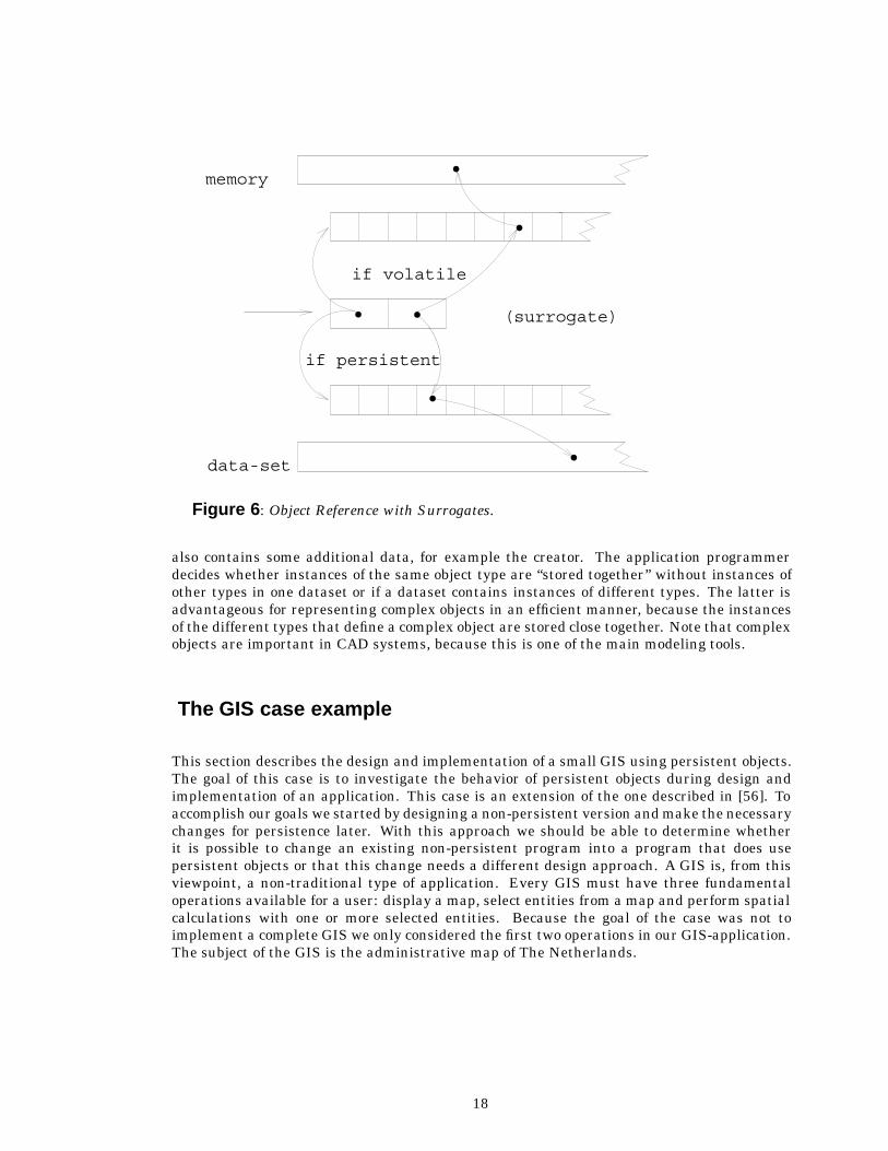
An object instance is identified by a surrogate [30], that is, the object id is not the actualaddress in memory but an indirection [45] to the actual locatation of the object. See figure 6for a graphic demonstration of the process. Each surrogate contains an indication whetherthe object instance is volatile, persistent or deleted. When, during the execution of a Procolprogram, an object is referenced, we have to check the first part of the surrogate. If the objectinstance is volatile, the surrogate contains a key than can be used to retrieve the memoryaddress of the instance variables. If the object instance is persistent, the surrogate containsa dataset identifier, and a key. With this dataset identifier and the key, the OMS is able toretrieve the actual memory address of the the instance variables of the persistent object inquestion.
The disadvantage of surrogates is that there is an extra indirection. However, surrogates haveseveral important advantages. They allow objects to be switched between the volatile andpersistent states, by modifying a part of the surrogate. We decided, based on the advantagesand disadvantages mentioned in section “Referential Integrity,” that the control of referentialintegrity is not required in Procol. However, the use of illegal references is signalled atrun-time. This is done by inspecting the surrogate and taking the appropriate measures. Ifa persistent object contains a reference to a volatile object, this volatile object is not savedautomatically. The proper way to program this case is to make the other object also persistent,if the referenced object is still needed in the future. The state of each object instance is storedas a single unit in contiguous memory. Instances of different sizes are no problem. The state
17
if persistent
(surrogate)
if volatile
data-set
memory
Figure 6: Object Reference with Surrogates.
also contains some additional data, for example the creator. The application programmerdecides whether instances of the same object type are “stored together” without instances ofother types in one dataset or if a dataset contains instances of different types. The latter isadvantageous for representing complex objects in an efficient manner, because the instancesof the different types that define a complex object are stored close together. Note that complexobjects are important in CAD systems, because this is one of the main modeling tools.
The GIS case example
This section describes the design and implementation of a small GIS using persistent objects.The goal of this case is to investigate the behavior of persistent objects during design andimplementation of an application. This case is an extension of the one described in [56]. Toaccomplish our goals we started by designing a non-persistent version and make the necessarychanges for persistence later. With this approach we should be able to determine whetherit is possible to change an existing non-persistent program into a program that does usepersistent objects or that this change needs a different design approach. A GIS is, from thisviewpoint, a non-traditional type of application. Every GIS must have three fundamentaloperations available for a user: display a map, select entities from a map and perform spatialcalculations with one or more selected entities. Because the goal of the case was not toimplement a complete GIS we only considered the first two operations in our GIS-application.The subject of the GIS is the administrative map of The Netherlands.
18

COUNTRY
PROVINCE PROVINCE
MUNICIPAL MUNICIPAL
Figure 7: Hierarchical structure of the map of the Netherlands.
The design of the non-persistent version
In this case the objects are the administrative units. The smallest administrative units arecalled municipalities (see Figure 7). The main geometric attribute of these objects is a polygondescribing the boundary of the municipality. Other attributes are the name and number ofthe municipality. We did not add any other thematic information, although it would notbe difficult to add this data in additional attributes. All these municipalities are groupedtogether into twelve larger administrative units called provinces each of which contains alist of child municipalities. Each municipality has a reference to its parent province, this tocreate a full duplex reference. The main geometric attribute of a province is, just like themunicipality, a polygon describing the boundary of the province. There is also a referenceattribute to the parent object called country. The boundary of the province is also a part of theboundary of some municipalities and the some boundaries of the provinces form the boundaryof the country.
To avoid redundant storage of the boundary information, another type of object called chainis introduced. A chain is a part of the border of a municipality that has a node at thebegin and end point. A node is a point where three or more municipalities meet (water andforeign countries are considered to be special cases). The attributes of the chain object arethe number of polyline points, an array of polyline coordinates and a reference to the left andright municipality. To create a full duplex reference, a list of child chains is added to all themunicipalities. With this central storage of boundary information the geometric attribute canbe removed from the municipality and province objects. So far, only an administrative logicalhierarchy is present. To add a simple spatial hierarchy, we add a bounding box attribute toall these objects. This makes a hierarchical entity search possible. Most objects are skippedduring an entity search, because a point can not be inside an administrative unit if it isoutside its bounding box.
A summary of the functional requirements for the GIS are:
� Display the map by showing either country, or province, or the municipality borders.
� Allow zoom-in operations on the map. The user indicates a rectangle on the map. TheGIS zooms in and redisplays the map.
19
� Allow a zoom-out operation on the map. The GIS zooms out to the original scaling andredisplays the map.
� Allow the user to select a municipality by clicking within its border. As a result the GISshould show the name of the municipality.
� Store the map (i.e. be an application that uses persistence).
� Allow the user to stop the GIS.
The implementation of the non-persistent version
The GIS contains two logically separate parts. One part translates the map data from acertain binary format into Procol objects. The other part is the actual GIS. These two partsform one program. Later in this article, in the persistent version of our GIS, these parts areactually split into two separate programs.
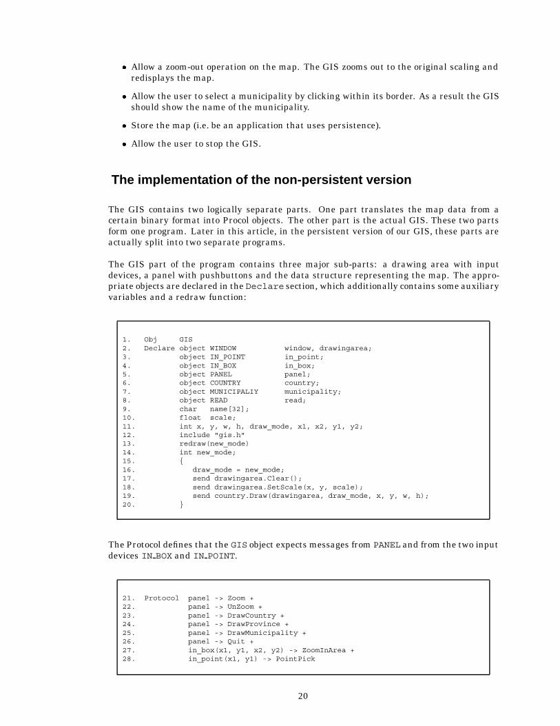
The GIS part of the program contains three major sub-parts: a drawing area with inputdevices, a panel with pushbuttons and the data structure representing the map. The appro-priate objects are declared in the Declare section, which additionally contains some auxiliaryvariables and a redraw function:
1. Obj GIS2. Declare object WINDOW window, drawingarea;3. object IN_POINT in_point;4. object IN_BOX in_box;5. object PANEL panel;6. object COUNTRY country;7. object MUNICIPALIY municipality;8. object READ read;9. char name[32];10. float scale;11. int x, y, w, h, draw_mode, x1, x2, y1, y2;12. include "gis.h"13. redraw(new_mode)14. int new_mode;15. {16. draw_mode = new_mode;17. send drawingarea.Clear();18. send drawingarea.SetScale(x, y, scale);19. send country.Draw(drawingarea, draw_mode, x, y, w, h);20. }
The Protocol defines that the GIS object expects messages from PANEL and from the two inputdevices IN BOX and IN POINT.
21. Protocol panel -> Zoom +22. panel -> UnZoom +23. panel -> DrawCountry +24. panel -> DrawProvince +25. panel -> DrawMunicipality +26. panel -> Quit +27. in_box(x1, y1, x2, y2) -> ZoomInArea +28. in_point(x1, y1) -> PointPick
20
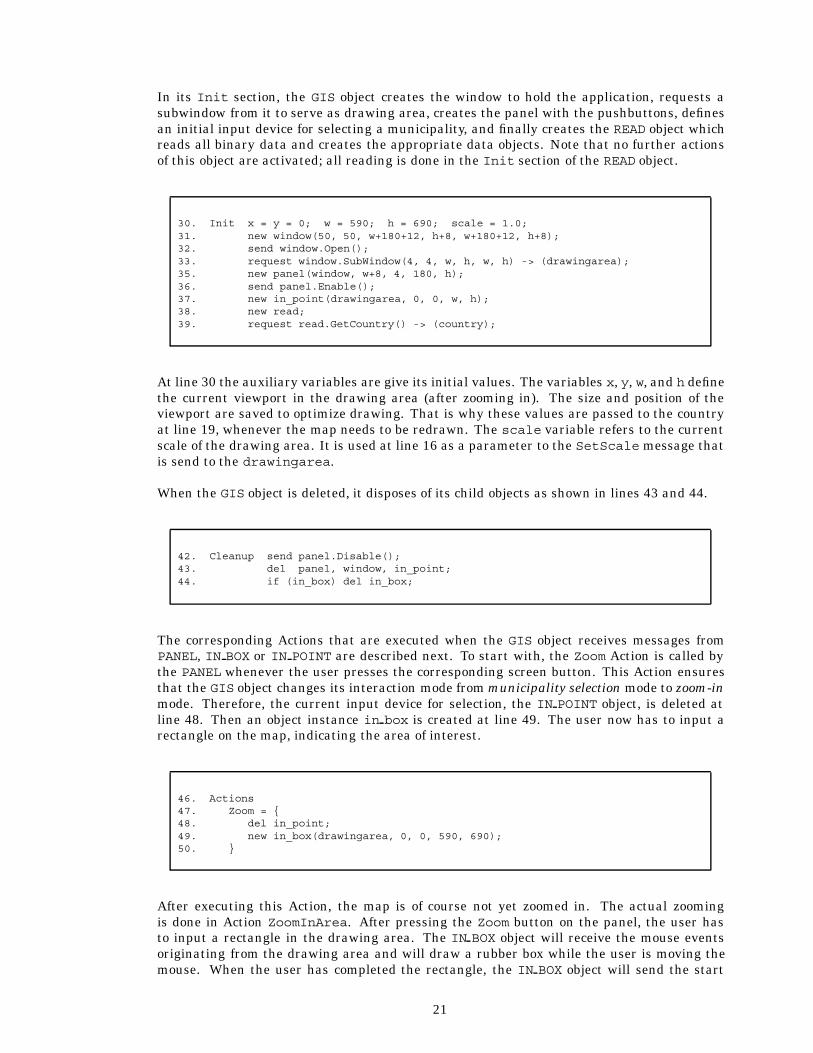
In its Init section, the GIS object creates the window to hold the application, requests asubwindow from it to serve as drawing area, creates the panel with the pushbuttons, definesan initial input device for selecting a municipality, and finally creates the READ object whichreads all binary data and creates the appropriate data objects. Note that no further actionsof this object are activated; all reading is done in the Init section of the READ object.
30. Init x = y = 0; w = 590; h = 690; scale = 1.0;31. new window(50, 50, w+180+12, h+8, w+180+12, h+8);32. send window.Open();33. request window.SubWindow(4, 4, w, h, w, h) -> (drawingarea);35. new panel(window, w+8, 4, 180, h);36. send panel.Enable();37. new in_point(drawingarea, 0, 0, w, h);38. new read;39. request read.GetCountry() -> (country);
At line 30 the auxiliary variables are give its initial values. The variables x, y, w, and h definethe current viewport in the drawing area (after zooming in). The size and position of theviewport are saved to optimize drawing. That is why these values are passed to the countryat line 19, whenever the map needs to be redrawn. The scale variable refers to the currentscale of the drawing area. It is used at line 16 as a parameter to the SetScale message thatis send to the drawingarea.
When the GIS object is deleted, it disposes of its child objects as shown in lines 43 and 44.
42. Cleanup send panel.Disable();43. del panel, window, in_point;44. if (in_box) del in_box;
The corresponding Actions that are executed when the GIS object receives messages fromPANEL, IN BOX or IN POINT are described next. To start with, the Zoom Action is called bythe PANEL whenever the user presses the corresponding screen button. This Action ensuresthat the GIS object changes its interaction mode from municipality selection mode to zoom-inmode. Therefore, the current input device for selection, the IN POINT object, is deleted atline 48. Then an object instance in box is created at line 49. The user now has to input arectangle on the map, indicating the area of interest.
46. Actions47. Zoom = {48. del in_point;49. new in_box(drawingarea, 0, 0, 590, 690);50. }
After executing this Action, the map is of course not yet zoomed in. The actual zoomingis done in Action ZoomInArea. After pressing the Zoom button on the panel, the user hasto input a rectangle in the drawing area. The IN BOX object will receive the mouse eventsoriginating from the drawing area and will draw a rubber box while the user is moving themouse. When the user has completed the rectangle, the IN BOX object will send the start
21

point and the end point to its creator, which is the GIS object. The Action in which thesecoordinates are eventually received is the ZoomInArea Action:
52. ZoomInArea = {53. del in_box;54. new in_point(drawingarea, 0, 0, 590, 690);55. x += (int) ((float)x1 / scale);56. y += (int) ((float)y1 / scale);57. w = (int) ((float)(x2-x1) / scale);58. h = (int) ((float)(y2-y1) / scale);59. if (w>h) scale = 590.0 / (float) w;60. else scale = 690.0 / (float) h;61. redraw(draw_mode);62. }
Important is that all the code for parsing events and for drawing rubber boxes is encapsulatedinto the objects IN BOX and IN POINT. The GIS object does not need to be concerned with theselow level details. The same holds for the creation and management of the screen buttons.This is encapsulated into the PANEL object. What is left for the GIS object, is to allocate thecorrect resources and to define the control flow of the application without being bothered withdistracting details.
The UnZoom Action restores the image of the map into a fully zoomed-out projection. Basi-cally this Action serves as a reset function. For practical reasons, the GIS object does notremember previous zoom operations and cannot gradually zoom out. Of course, there is noparticular reason why this could not be implemented in a more sophisticated version of theGIS application.
64. UnZoom = {65. x = y = 0; w = 590; h = 690; scale = 1.0;66. redraw(draw_mode); /* draw in current drawmode */67. if (in_box) del in_box;68. }
The panel has three buttons to draw the map, depending on the level of detail the user wantsto see. The Actions called on activation of these buttons are:
70. DrawCountry = { redraw(DRAWMODECOUNTRY); }71. DrawProvince = { redraw(DRAWMODEPROVINCE); }72. DrawMunicipality = { redraw(DRAWMODEMUNICIPALIY); }
Furthermore, the panel has a button to stop the GIS application. When this button isactivated, the GIS object will ask its creator to delete it.
74. Quit = { send creator.Stop(NORMAL); }
22
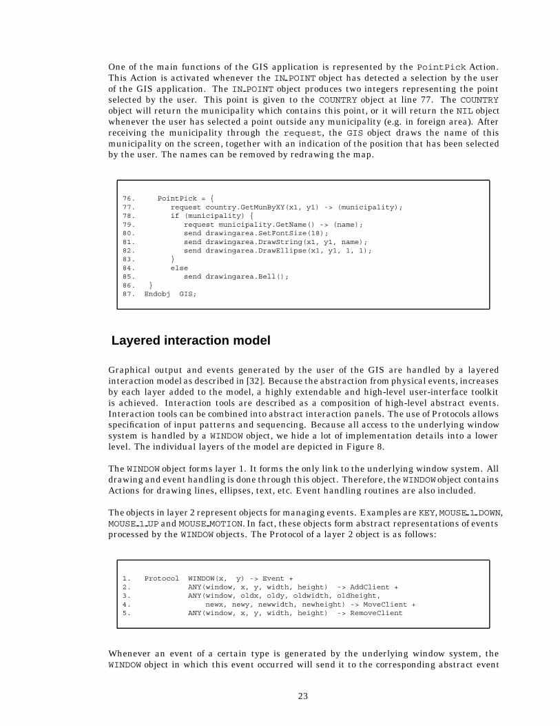
One of the main functions of the GIS application is represented by the PointPick Action.This Action is activated whenever the IN POINT object has detected a selection by the userof the GIS application. The IN POINT object produces two integers representing the pointselected by the user. This point is given to the COUNTRY object at line 77. The COUNTRYobject will return the municipality which contains this point, or it will return the NIL objectwhenever the user has selected a point outside any municipality (e.g. in foreign area). Afterreceiving the municipality through the request, the GIS object draws the name of thismunicipality on the screen, together with an indication of the position that has been selectedby the user. The names can be removed by redrawing the map.
76. PointPick = {77. request country.GetMunByXY(x1, y1) -> (municipality);78. if (municipality) {79. request municipality.GetName() -> (name);80. send drawingarea.SetFontSize(18);81. send drawingarea.DrawString(x1, y1, name);82. send drawingarea.DrawEllipse(x1, y1, 1, 1);83. }84. else85. send drawingarea.Bell();86. }87. Endobj GIS;
Layered interaction model
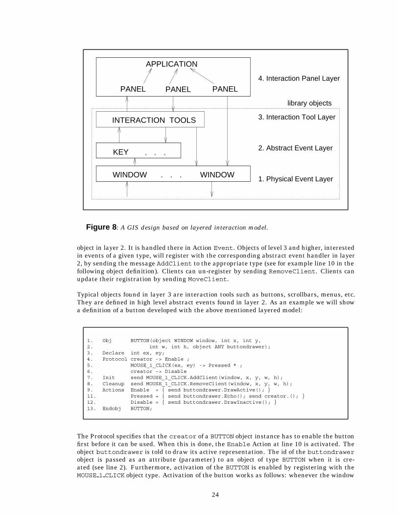
Graphical output and events generated by the user of the GIS are handled by a layeredinteraction model as described in [32]. Because the abstraction from physical events, increasesby each layer added to the model, a highly extendable and high-level user-interface toolkitis achieved. Interaction tools are described as a composition of high-level abstract events.Interaction tools can be combined into abstract interaction panels. The use of Protocols allowsspecification of input patterns and sequencing. Because all access to the underlying windowsystem is handled by a WINDOW object, we hide a lot of implementation details into a lowerlevel. The individual layers of the model are depicted in Figure 8.
The WINDOW object forms layer 1. It forms the only link to the underlying window system. Alldrawing and event handling is done through this object. Therefore, the WINDOW object containsActions for drawing lines, ellipses, text, etc. Event handling routines are also included.
The objects in layer 2 represent objects for managing events. Examples are KEY,MOUSE 1 DOWN,MOUSE 1 UP and MOUSE MOTION. In fact, these objects form abstract representations of eventsprocessed by the WINDOW objects. The Protocol of a layer 2 object is as follows:
1. Protocol WINDOW(x, y) -> Event +2. ANY(window, x, y, width, height) -> AddClient +3. ANY(window, oldx, oldy, oldwidth, oldheight,4. newx, newy, newwidth, newheight) -> MoveClient +5. ANY(window, x, y, width, height) -> RemoveClient
Whenever an event of a certain type is generated by the underlying window system, theWINDOW object in which this event occurred will send it to the corresponding abstract event
23
3. Interaction Tool Layer
2. Abstract Event Layer
1. Physical Event Layer
4. Interaction Panel Layer
library objects
INTERACTION TOOLS
WINDOW . . . WINDOW
. . .KEY
PANEL PANEL PANEL
APPLICATION
Figure 8: A GIS design based on layered interaction model.
object in layer 2. It is handled there in Action Event. Objects of level 3 and higher, interestedin events of a given type, will register with the corresponding abstract event handler in layer2, by sending the message AddClient to the appropriate type (see for example line 10 in thefollowing object definition). Clients can un-register by sending RemoveClient. Clients canupdate their registration by sending MoveClient.
Typical objects found in layer 3 are interaction tools such as buttons, scrollbars, menus, etc.They are defined in high level abstract events found in layer 2. As an example we will showa definition of a button developed with the above mentioned layered model:
1. Obj BUTTON(object WINDOW window, int x, int y,2. int w, int h, object ANY buttondrawer);3. Declare int ex, ey;4. Protocol creator -> Enable ;5. MOUSE_1_CLICK(ex, ey) -> Pressed * ;6. creator -> Disable7. Init send MOUSE_1_CLICK.AddClient(window, x, y, w, h);8. Cleanup send MOUSE_1_CLICK.RemoveClient(window, x, y, w, h);9. Actions Enable = { send buttondrawer.DrawActive(); }11. Pressed = { send buttondrawer.Echo(); send creator.(); }12. Disable = { send buttondrawer.DrawInactive(); }13. Endobj BUTTON;
The Protocol specifies that the creator of a BUTTON object instance has to enable the buttonfirst before it can be used. When this is done, the Enable Action at line 10 is activated. Theobject buttondrawer is told to draw its active representation. The id of the buttondrawerobject is passed as an attribute (parameter) to an object of type BUTTON when it is cre-ated (see line 2). Furthermore, activation of the BUTTON is enabled by registering with theMOUSE 1 CLICK object type. Activation of the button works as follows: whenever the window
24
system generates an event notifying that the user has pressed the first mouse button, it isreceived by a WINDOW object. The WINDOW object then sends a message to the appropriateabstract event handler. This object will in its turn send a message to the corresponding clientwithout specifying an Action name. The receiving object (in this case the BUTTON) is free todynamically bind the message to an appropriate Action. Therefore, line 5 actually binds themessage to the Action Pressed. When the Action is activated, the BUTTON is highlighted atline 11 by sending the Echo message to the buttondrawer. Then the creator is notifiedby sending it a message, again without naming the Action. The creator can again bind thismessage from the BUTTON to any appropriate Action, possibly depending on its Protocol state.
The hierarchical data structure
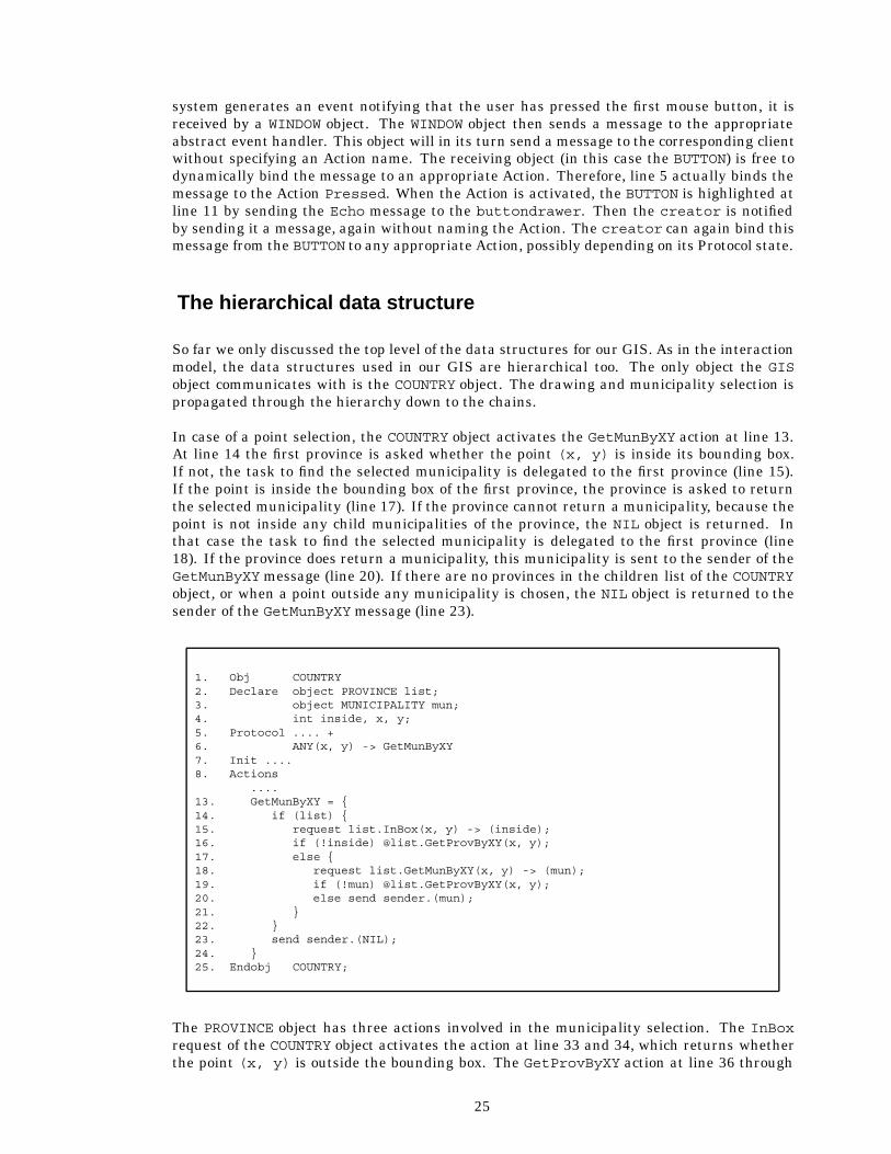
So far we only discussed the top level of the data structures for our GIS. As in the interactionmodel, the data structures used in our GIS are hierarchical too. The only object the GISobject communicates with is the COUNTRY object. The drawing and municipality selection ispropagated through the hierarchy down to the chains.
In case of a point selection, the COUNTRY object activates the GetMunByXY action at line 13.At line 14 the first province is asked whether the point (x, y) is inside its bounding box.If not, the task to find the selected municipality is delegated to the first province (line 15).If the point is inside the bounding box of the first province, the province is asked to returnthe selected municipality (line 17). If the province cannot return a municipality, because thepoint is not inside any child municipalities of the province, the NIL object is returned. Inthat case the task to find the selected municipality is delegated to the first province (line18). If the province does return a municipality, this municipality is sent to the sender of theGetMunByXY message (line 20). If there are no provinces in the children list of the COUNTRYobject, or when a point outside any municipality is chosen, the NIL object is returned to thesender of the GetMunByXY message (line 23).
1. Obj COUNTRY2. Declare object PROVINCE list;3. object MUNICIPALITY mun;4. int inside, x, y;5. Protocol .... +6. ANY(x, y) -> GetMunByXY7. Init ....8. Actions
....13. GetMunByXY = {14. if (list) {15. request list.InBox(x, y) -> (inside);16. if (!inside) @list.GetProvByXY(x, y);17. else {18. request list.GetMunByXY(x, y) -> (mun);19. if (!mun) @list.GetProvByXY(x, y);20. else send sender.(mun);21. }22. }23. send sender.(NIL);24. }25. Endobj COUNTRY;
The PROVINCE object has three actions involved in the municipality selection. The InBoxrequest of the COUNTRY object activates the action at line 33 and 34, which returns whetherthe point (x, y) is outside the bounding box. The GetProvByXY action at line 36 through
25

47, is almost identical to the GetMunByXY action of the COUNTRY object, except that the nextprovince is represented by the object next instead of by list. The action GetMunByXY atlines 48 through 55, has a similar structure. The municipality, represented by list is askedwhether the point (x, y) is inside its borders (line 50). If not, the task to find the selectedmunicipality is delegated to that first municipality (line 52). If the selected point is inside,the municipality is returned to the requesting object (line 51). If this province has no childmunicipalities, or the selected point is not inside any child municipality of the province, theNIL object is returned (line 55).
1. Obj PROVINCE(....)2. Declare ....3. object MUNICIPALITY list;4. object MUNICIPALITY mun;5. object PROVINCE next;6. int maxx, maxy, minx, miny,7. int x, y, inside;8. Protocol .... +9. ANY(x, y) -> InBox +10. ANY(x, y) -> GetProvByXY +11. ANY(x, y) -> GetMunByXY12. Init ....13. Actions
....33. InBox = { send sender.(x<=maxx && x>=minx &&34. y<=maxy && y>=miny);35. }36. GetProvByXY = {37. if (next) {38. request next.InBox(x, y) -> (inside);39. if (!inside) @next.GetProvByXY(x, y);40. else {41. request next.GetMunByXY(x, y) -> (mun);42. if (!mun) @next.GetProvByXY(x, y);43. else send sender.(mun);44. }45. }46. send sender.(NIL);47. }48. GetMunByXY = {49 if (list) {50. request list.Inside(x, y) -> (inside);51. if (inside) send sender.(list);52. else @list.GetMunByXY(x, y);53. }54. send sender.(NIL);55. }56. Endobj PROVINCE;
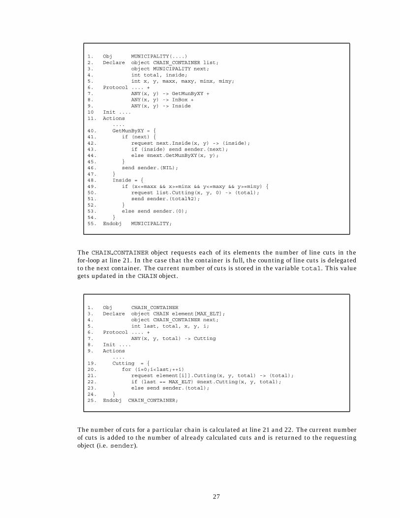
The MUNICIPALITY object has two actions involved with searching. The GetMunByXY actionat line 40 through 50 is identical to same action of the PROVINCE object. The action Insideat line 48 through 54 first checks whether the point is inside the bounding box (line 49). If so,a point-in-polygon test is executed (line 50 and 51). It requests the number of line cuts madewith each of its borders when going from point (x, y) to point (infinite, y). If the totalnumber of cuts is odd, the point (x, y) is inside the municipality. Otherwise it is outsidethe municipality. If point (x, y) is not inside the bounding box, false is returned.
26
1. Obj MUNICIPALITY(....)2. Declare object CHAIN_CONTAINER list;3. object MUNICIPALITY next;4. int total, inside;5. int x, y, maxx, maxy, minx, miny;6. Protocol .... +7. ANY(x, y) -> GetMunByXY +8. ANY(x, y) -> InBox +9. ANY(x, y) -> Inside10 Init ....11. Actions
....40. GetMunByXY = {41. if (next) {42. request next.Inside(x, y) -> (inside);43. if (inside) send sender.(next);44. else @next.GetMunByXY(x, y);45. }46. send sender.(NIL);47. }48. Inside = {49. if (x<=maxx && x>=minx && y<=maxy && y>=miny) {50. request list.Cutting(x, y, 0) -> (total);51. send sender.(total%2);52. }53. else send sender.(0);54. }55. Endobj MUNICIPALITY;
The CHAIN CONTAINER object requests each of its elements the number of line cuts in thefor-loop at line 21. In the case that the container is full, the counting of line cuts is delegatedto the next container. The current number of cuts is stored in the variable total. This valuegets updated in the CHAIN object.
1. Obj CHAIN_CONTAINER3. Declare object CHAIN element[MAX_ELT];4. object CHAIN_CONTAINER next;5. int last, total, x, y, i;6. Protocol .... +7. ANY(x, y, total) -> Cutting8. Init ....9. Actions
....19. Cutting = {20. for (i=0;i<last;++i)21. request element[i]].Cutting(x, y, total) -> (total);22. if (last == MAX_ELT) @next.Cutting(x, y, total);23. else send sender.(total);24. }25. Endobj CHAIN_CONTAINER;
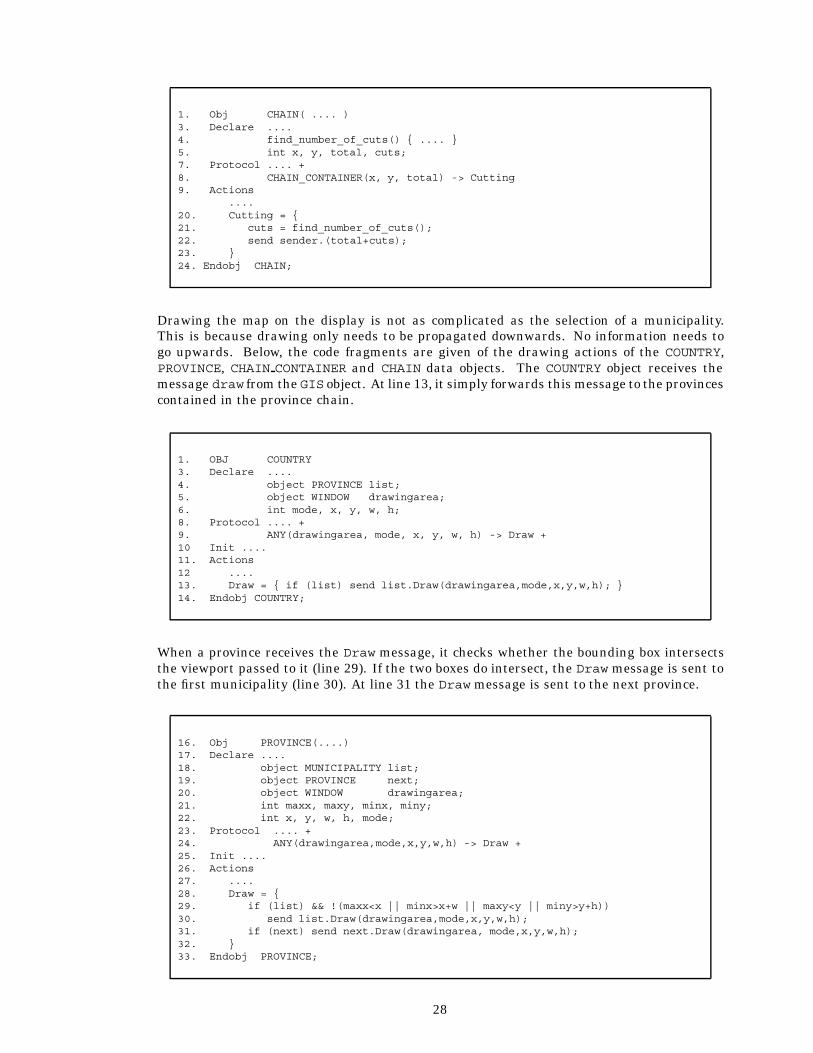
The number of cuts for a particular chain is calculated at line 21 and 22. The current numberof cuts is added to the number of already calculated cuts and is returned to the requestingobject (i.e. sender).
27
1. Obj CHAIN( .... )3. Declare ....4. find_number_of_cuts() { .... }5. int x, y, total, cuts;7. Protocol .... +8. CHAIN_CONTAINER(x, y, total) -> Cutting9. Actions
....20. Cutting = {21. cuts = find_number_of_cuts();22. send sender.(total+cuts);23. }24. Endobj CHAIN;
Drawing the map on the display is not as complicated as the selection of a municipality.This is because drawing only needs to be propagated downwards. No information needs togo upwards. Below, the code fragments are given of the drawing actions of the COUNTRY,PROVINCE, CHAIN CONTAINER and CHAIN data objects. The COUNTRY object receives themessage draw from the GIS object. At line 13, it simply forwards this message to the provincescontained in the province chain.
1. OBJ COUNTRY3. Declare ....4. object PROVINCE list;5. object WINDOW drawingarea;6. int mode, x, y, w, h;8. Protocol .... +9. ANY(drawingarea, mode, x, y, w, h) -> Draw +10 Init ....11. Actions12 ....13. Draw = { if (list) send list.Draw(drawingarea,mode,x,y,w,h); }14. Endobj COUNTRY;
When a province receives the Draw message, it checks whether the bounding box intersectsthe viewport passed to it (line 29). If the two boxes do intersect, the Draw message is sent tothe first municipality (line 30). At line 31 the Draw message is sent to the next province.
16. Obj PROVINCE(....)17. Declare ....18. object MUNICIPALITY list;19. object PROVINCE next;20. object WINDOW drawingarea;21. int maxx, maxy, minx, miny;22. int x, y, w, h, mode;23. Protocol .... +24. ANY(drawingarea,mode,x,y,w,h) -> Draw +25. Init ....26. Actions27. ....28. Draw = {29. if (list) && !(maxx<x || minx>x+w || maxy<y || miny>y+h))30. send list.Draw(drawingarea,mode,x,y,w,h);31. if (next) send next.Draw(drawingarea, mode,x,y,w,h);32. }33. Endobj PROVINCE;
28

The MUNICIPALITY object has exactly the same Draw action as the PROVINCE object. It sendsthe message to its first CHAIN CONTAINER object and also to the next municipality.
The CHAIN CONTAINER object receives the Draw message from its parent municipality andthe Draw action at line 65 is activated. In this case the Draw message is not a result of anormal send statement to the containing chains and next container, but it is delegated to them[10, 31, 50]. This is a good example of the power of delegation. Because delegation is used,receivers of the Draw message, issued at line 67 and 69, think that the MUNICIPALITY objectis the sender, instead of chain container, which is the actual sender. This use of delegationis necessary to avoid drawing the map twice. As each chain has two parents, it receivesfrom both of them the Draw message. However, only the message received from the leftmunicipality is used to actually draw the chain. In order to achieve this, the CHAIN objectwill inspect whether the sending object is the same object it assumes to be its left parent(remember that a chain has a left parent, and a right parent). If this is the case, the chaingets drawn, else the message is ignored.
54. Obj CHAIN_CONTAINER55. Declare ....56. object CHAIN element[MAX_ELT];57. object CHAIN_CONTAINER next;58. object WINDOW drawingarea;59. int last, mode, i, MAX_ELT;60. int x, y, w, h;61. Protocol .... +62. ANY(drawingarea, mode, x, y, w ,h) -> Draw +63. Init ....64. Actions65. Draw = {66. for (i=0;i<last;++i)67. @element[i].Draw(drawingarea,mode,x,y,w,h);68. if (last == max)69. @next.Draw(drawingarea,mode,sender,x,y ,w,h);70. }71. Endobj CHAIN_CONTAINER;
The CHAIN object receives the Draw message and the Draw action at line 89 is subsequentlyactivated. The sender is compared with its left parent. If they are identical, i.e. have thesame id, the chain is drawn in the selected mode. The modes are: draw the country border,draw the province border and draw all borders. At lines 76 through 80 the function to drawthe province borders is declared. At line 77 and 78 the left and right parent are asked togive their province id4. If the left parent and the right parent do not have the same id, thechain is drawn. At line 81 through 85 the function to draw the country border is declared. Atline 85 and 86 the id of the left and right parent are requested. If at least one of them is thespecial municipality with id equal to 0, the chain is drawn. The municipality with id equal to0 represents foreign countries and water.
4The province id is represented by an integer, and decided upon by the supplier of the map. The province id is notequal to the object id of the corresponding PROVINCE object.
29

72. Obj CHAIN(object MUNICIPALITY m_left, object MUNICIPALITY m_right, ....)73. Declare object WINDOW drawingarea;74. int left, right, x, y, w, h, mode;;75. draw_chain() {....}76. draw_prov() {77. request m_left.GetProvID() -> (left);78. request m_right.GetProvID() -> (right);79. if (left != right) draw_chain();80. }81. draw_country() {82. request m_left.GetID() -> (left);83. request m_right.GetID() -> (right);84. if (left==0 || right==0) draw_chain();85. }86. Protocol .... +87. ANY(drawingarea,mode, x, y, w, h) -> Draw88. Actions89. Draw = { if (sender == left) {90. switch(mode) {91. case 1: draw_country(); break;92. case 2: draw_prov(); break;93. case 3: draw_chain();94. }95. }96. }97. Endobj CHAIN;
The translation of the binary data
Our approach of translating input data into Procol objects, still without considering persis-tence, is a top-down approach of constructing the administrative hierarchy. First the COUNTRYobject is created. This object forms the root of the hierarchy. After the creation of the COUNTRYobject the PROVINCE, MUNICIPALITY, and CHAIN objects are created at line 9 through 11 re-spectively, by the objects PROV READ, MUN READ and CHAIN READ. The object CHAIN READ hastwo scaling parameters for the geometric data. Note that there is only one action that canbe executed by the READ object. The action is the GetCountry action, and is assumed to becalled by the creator of the READ object instance only. In this example, the creator is equalto the GIS object described before. The only thing the action does, is to return the id of theCOUNTRY object recently created (in the Init section).
1. Obj READ2. Declare include "gis.h"3. object PROV_READ prov_read;4. object MUN_READ mun_read;5. object CHAIN_READ chain_read;6. object COUNTRY country;7. Protocol creator -> GetCountry8. Init new country;9. new prov_read(country);10. new mun_read(country);11. new chain_read(595, 700, country);12. Actions GetCountry = { send sender.(country); }13. Endobj READ;
An impression of how the binary map data is read by the MUN READ object is given in the nextcode fragment, assuming the PROVINCE and COUNTRY object already exist.
30

1. Obj MUN_READ(object COUNTRY country)2. Declare include "gis.h";3. object MUNICIPALITY municipality;4. object PROVINCE province;5. int p_number, m_number;6. string name[20];7. start_municipality_read() { .... }8. last_municipality() { .... }9. read_next_municipality_number() { .... }10. ready_municipality_read() { .... }11. Init start_municipality_reading();12. while(!last_municipality()) {13. read_next_municipality_number(&m_number, &p_number, name);14. request country.get_province(p_number) -> (province);15. new municipality(m_number, name, province);16. }17. ready_municipality_read();18. Endobj MUN_READ;
At line 12 through 16 the municipalities are processed. The next municipality is read at line13, returning the municipality id, the Province id and the name of the municipality. At line14 the parent PROVINCE object is requested from the COUNTRY object. This PROVINCE objectis needed as an attribute of the MUNICIPALITY object. The MUNICIPALITY object is createdat line 15.
When each of the map objects is created, it inserts itself into its corresponding parent’schild-list. These insertions are activated in the Init section of the objects. The lists areimplemented as linked lists. The parent has a reference to its first child, and that child has areference to the next child. This implementation does not work for the CHAIN objects becauseeach chain has two parents. So a CHAIN CONTAINER object is implemented in which a numberof chains can be stored. These CHAIN CONTAINER objects are linked together in the same wayas the provinces and the municipalities.
The modification with persistent objects
As stated in this article the only needed changes in code should be:
� To create a persistent object the statement persistent �objectname� in �dataset�has to be inserted after the new �objectname� statement.
� Instead of creating the whole hierarchical administrative unit structure, the statementretrieve country from "dataset" has to be added.
The first step taken in the process of modifying our GIS into a persistent one was to splitup the GIS and the data reading part into two separate programs. The final GIS programcontains no read or write statements; it only refers to persistent objects by retrieving themfrom a dataset. As an aside, by splitting our GIS into two separate applications we show thatpersistent objects can be shared and transported between different applications. Figure 9shows the design of the resulting programs.
The data translation program creates a dataset for every object type in the map structure;this shows that references to persistent objects can extend to datasets other than the onewhere the reference actually takes place.
31

data persistent objects
READ GIS
Figure 9: Design of the example GIS.
The resulting persistent data structure has the same hierarchical structure as the data struc-ture in the non-persistent version. It has one single root, the country. The country hasreferences to all existing provinces, and these provinces contain references to all municipal-ities. This type of data structure can be identified by one single reference root. Retrieval ofthe data structure is simple, as one only has to get hold of the root of the structure, in ourcase the COUNTRY object.
It is not a prerequisite of data structures that they should be hierarchical to be used in thispersistent manner. The data structure itself may be cyclic, and the data structure may wellhave the form of a graph. Of importance is that we need to be able to identify a certainentrance to the data structure. In this example, the entrance is formed by the COUNTRYobject. As it is the only instance of its type it is possible to retrieve it from the "holland.pp"dataset uniquely. It would have been possible to also define an extra entrance in the form of,say, an index structure on the name of the municipalities. This would have enabled the GISto make selections based on municipality name and highlight the corresponding municipalityon the map, for instance. This index structure could have been retrieved from a datasetbased on its type, in the same manner we retrieved the country. In this case we would havehad two entrances to the same data structure, and different interpretations and usage of thedata structure could be envisioned. In the GIS context, two different indexing techniques areimportant. The first common search operation is based on geometric properties (e.g. by usingan R-tree or our hierarchical bounding boxes approach). The second common search operationis based upon topologic properties of objects. A typical example of the type of queries involvedis “give all municipalities that are adjacent to the current municipality”.
Retrieving persistent objects from a dataset
We saw that the data structure is retrieved from its persistent storage by retrieving theCOUNTRY object instance (the root of the data structure) from its corresponding dataset(i.e. "holland.pp"). The assumption is that the dataset contains only one instance of thetype COUNTRY, and issuing the retrieve primitive will produce the one and only COUNTRYobject instance forming the root of our data structure. If the dataset contains more than oneinstance, one amongst them is returned (in practice the oldest one). If wanted, the nextprimitive can be used to retrieve the other COUNTRY objects from the dataset. Retrievingthe country is the only thing the GIS object has to do to retrieve the data structure from its
32

persistent storage. That is because the COUNTRY object contains references to a number ofpersistent objects. While accessing these references, for instance while drawing the map, theProcol runtime system will detect that these references are references to persistent objects.The corresponding datasets are then mapped to main memory (by the Operating System) andthe persistent objects are automatically loaded. After retrieving the country, the GIS cansend it messages, and the COUNTRY object can never determine whether it was created in thesame program run as the GIS or that it has been retrieved at a later stage.
Only two lines of code need to be changed in the GIS object. The non-persistent version of theGIS reads in the country by creating a special READ object instance, shown in the followingcode segment.
1. Obj GIS..38. new read;39. request read.GetCountry() -> (country);...
The persistent version of the GIS, retrieves the COUNTRY object instance from a dataset, thatis all that needs to be done to make the GIS persistent.
1. Obj GIS..38. retrieve country from "holland.pp";...
Of course, the objects created by the READ object need to be made persistent and stored in adataset, before they can be retrieved in the manner shown above. To begin with, the READobject will not only create the COUNTRY object instance, but will also make it persistent. Thisis done at line 8 in the following segment.
1. Obj READ2. Declare ......7. Protocol ....8. Init new country; persistent country in "holland.pp";9. ....12. Actions ....13. Endobj READ;
Furthermore, the objects PROV READ, MUN READ, CHAIN and CHAIN READ will also have tomake the objects they create persistent. They therefore also contain persistent statementssimilar to the one descibe dat line 8. Summarizing, to make the non-persistent GIS persistent,one retrieve statement and five persistent statements suffice.
33
Practical problems
In the current implementation of the Procol compiler, it is not possible to use variable sizeobjects. The size of objects is static for every instance of a specific object type, hence the sizeof object instances may not change after creation. In our case we have arrays of boundarycoordinates, normally having different sizes. It is obvious that the linked list approach toimplement arrays adds a lot of overhead in general. In our case we created an object witha static array large enough to contain the largest chain, because the maximum number ofcoordinate pairs of the chains was not very large. A flexible solution to this problem whendealing with large array’s is to create an array object with a small static array, and link theseobjects together when the number of elements exceeds the size of the static array.
The natural place to link objects in a data structure together is in the Init section of the childobject, as done in our non-persistent GIS. This is not possible when dealing with persistentobjects. When an object is made persistent, its id is changed. This id change is not known byobjects already referencing to this object; referential integrity can no longer be guaranteed.To avoid dangling references, all references to an object should be made after the object ismade persistent. A more drastic solution is the introduction of deep persistence; i.e. whenan object is made persistent, all its child objects are made persistent too. However, thismethod prevents the possibility of using volatile and persistent objects in one hierarchicaldata structure.
Another aspect that became apparent was an dataset management problem. The datasets areall registered in a dataset table (a kind of "yellow pages"). Each table entry contains a datasetnumber, and full path and filename where the dataset can be found. In this way it is possible tocreate two datasets with the same name in different directories. When more than one datasetis used to store the objects, the reference to an object instance which is stored in a differentdataset, contains also the dataset-number of the dataset where that specific object instanceis stored. Using this number, the dataset-table is consulted and the location of the datasetis extracted from there. But, when the datasets are copied or moved to another directory,the location in the dataset-table does no longer match the new location of this dataset. Thisproblem arises because the user can move, copy, or delete datasets in the normal Unix shell. Ifthe Procol runtime system would manage these tasks, like most relational database systemsdo, this problem would not occur. This runtime system is currently being developed.
Persistent program behavior
The translation program and the GIS application have been implemented and timed with/bin/time on a Sun Sparcstation IPC, with SunOS Release 4.1.1. and Sun OpenWindows.The different timings are summarized in Figure 10. Timing 1 shows the time needed by anon-persistent version of the GIS to start, to convert the map data into objects, to draw theentire map, and to immediately stop. Timing 2 indicates the time needed to start a persistentobjects based GIS, to draw the entire map, and again to immediately stop. Of importancehere is the difference between 1 and 2. Timing 3 refers to converting the map from binarydata into Procol objects without making them persistent. Timing 4 refers to converting themap from binary data into persistent objects. Timing 5 show the time needed to start the GISand without drawing the map, to stop immediately. The GIS uses persistent objects in thiscase. Timing 6 indicates the time needed to draw the entire map (excluding the time neededto start and stop the GIS). Finally, timing 7 indicates the time needed by the Procol run-timesystem to entirely retrieve the map from its persistent storage into main-memory.
These figures are shown to indicate the dramatic difference between timing 1 and 2. Thedifference is mainly introduced by the time needed to convert the (relatively unstructured)
34
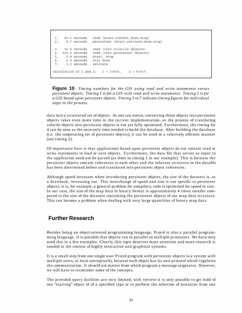
1. 40.1 seconds read (start,convert,draw,stop)2. 4.7 seconds persistent (start,retrieve,draw,stop)
3. 36.4 seconds read (into volatile objects)4. 425.6 seconds read (into persistent objects)5. 0.8 seconds start, stop6. 2.9 seconds only draw7. 1.0 seconds retrieve
calculation of 1 and 2: 1 = 3+5+6, 2 = 5+6+7.
Figure 10: Timing numbers for the GIS using read and write statements versuspersistent objects. Timing 1 is for a GIS with read and write statements. Timing 2 is fora GIS based upon persistent objects. Timing 3 to 7 indicate timing figures for individualsteps in the process.
data into a structured set of objects. As one can notice, converting these objects into persistentobjects takes even more time in the current implementation, as the process of translatingvolatile objects into persistent objects is not yet fully optimized. Furthermore, the timing for4 can be seen as the once-only time needed to build the database. After building the database(i.e. the cooperating set of persistent objects), it can be used in a relatively efficient manner(see timing 2).
Of importance here is that applications based upon persistent objects do not contain read orwrite statements to load or save objects. Furthermore, the data file that serves as input tothe application need not be parsed (as done in timing 1 in our example). This is because thepersistent objects contain references to each other and the inherent structure in the datafilehas been determined before and translated into persistent object references.
Although speed increases when introducing persistent objects, the size of the datasets is, asa drawback, increasing too. This interchange of speed and size is not specific to persistentobjects, it is, for example, a general problem for compilers; code is optimized for speed or size.In our case, the size of the map data in binary format is approximately 4 times smaller com-pared to the size of the datasets containing the persistent objects of our map data structure.This can become a problem when dealing with very large quantities of binary map data.
Further Research
Besides being an object-oriented programming language, Procol is also a parallel program-ming language. It is possible that objects run in parallel on multiple processors. We have onlyused this in a few examples. Clearly, this topic deserves more attention and more research isneeded in the context of highly interactive and graphical systems.
It is a small step from one single user Procol program with persistent objects to a system withmultiple users, at least conceptually, because each object has its own protocol which regulatesthe communication. It should not matter from which program a message originates. However,we will have to reconsider some of the concepts.
The provided query facilities are very limited; with retrieve it is only possible to get hold ofone “starting” object id of a specified type or to perform the selection of instances from one
35

set (object type) at a time. More complex queries have to be programmed into the objects (theProcol program). Attention has to be paid to avoid object types becoming too specific. Thatis in contradiction with one of the basic principles of databases of data being independent ofapplications. More research in this area is necessary.
References
[1] D.J. Abel. SIRO-DBMS: A database tool-kit for Geographical Information Systems. InternationalJournal of Geographical Information Systems, 3(2):103–116, 1989.
[2] Malcolm P. Atkinson and O. Peter Buneman. Types and persistence in database programminglanguages. ACM Computing Surveys, 19(2):105–190, June 1987.
[3] M.P. Atkinson, P.J. Bailey, K.J. Chisholm, P.W. Cockshott, and R. Morrison. An approach topersistent programming. The Computer Journal, 26(4):360–365, 1983.
[4] F. Bancilhon, G. Barbedette, V. Benzaken, C. Delobel, S. Gamerman, C. Lecluse, P. Pfeffer,P. Richard, and F. Velez. The design and implementationofO2, an object-oriented database system.In Advances in Object-Oriented Database Systems, 2nd International Workshop on Object-OrientedDatabase Systems, Bad Munster am Stein-Ebernburg, FRG, pages 1–22, September 1988.
[5] R. Bayer and E. McCreight. Organization and maintenance of large ordered indexes. Acta Infor-matica, 1:173–189, 1973.
[6] K. Bennis, B. David, I. Morize-Quilio, J.M. Thevenin, and Y. Viemont. GeoGraph: A topologicalstorage model for extensible GIS. In Auto-Carto 10, Baltimore, pages 349–367, March 1991.
[7] K. Bennis, B. David, I. Quilio, and Y. Viemont. GeoTropics database support alternatives forgeographic applications. In 4th International Symposium on Spatial Data Handling, Zurich,Switzerland, pages 599–610, July 1990.
[8] Jon Louis Bentley. Multidimensional binary search trees used for associative searching. Commu-nications of the ACM, 18(9):509–517, September 1975.
[9] E.H. Blake and S. Cook. On including part hierarchies in object-oriented languages, with animplementation in Smalltalk. In ECOOP ’87, pages 41–50, 1987.
[10] Jan van den Bos and Chris Laffra. "Procol - An Object Language with Protocols, Delegation andCon- straints", Acta Informatica, 28:511–538, August, 1991.
[11] Arthur Chance and Richard G. Newell and David G. Theriault. An Object-Oriented GIS – Issuesand Solutions. In Proceedings EGIS’91, Second European Conference on Geographical InformationSystems, pages 179–188, April 1991.
[12] Peter Pin-Shan Chen. The entity-relationship model – Toward a unified view of data. ACMTransactions on Database Systems, 1(1):9–36, March 1976.
[13] E.F. Codd. A relational model of data for large shared data banks. Communications of the ACM,13(6):377–387, June 1970.
[14] Douglas Comer. The ubiquitous B-Tree. ACM Computing Surveys, 11(2):121–137, June 1979.
[15] Brad J. Cox. Object-OrientedProgramming – An Evolutionary Approach. Addison-Wesley, Reading,Mass., 1986.
[16] WalterC. Dietrich, Jr., Lee R. Nackman, Christine J. Sundaresan, and Franklin Gracer. TGMS: Anobject-orientedsystem for programming geometry. Software – Practice and Experience, 19(10):979–1013, October 1989.
[17] Max Egenhofer and Andrew Frank. Panda: An extensible DBMS supporting object-orientedsoftware techniques. In Database Systems in Office, Engineering, and Scientific Environment,New York, March 1989.
[18] Max J. Egenhofer and Andrew U. Frank. Object-oriented modeling in GIS: Inheritance andPropagation. In Auto-Carto 9, Baltimore, pages 588–598, April 1989.
[19] ESRI. ARC/INFO – The Georelational Model Revisited. ARC News Winter, page 9, 1989.
[20] Christos Faloutsos, Timos Sellis, and Nick Roussopoulos. Analysis of object oriented spatial accessmethods. ACM SIGMOD, 16(3):426–439, December 1987.
36
[21] Andrew U. Frank. Multiple inheritance and genericity for the integration of a database man-agement system in an object-oriented approach. In Advances in Object-Oriented Database Sys-tems, 2nd International Workshop on Object-Oriented Database Systems, Bad Munster am Stein-Ebernburg, FRG, pages 268–273, September 1988.
[22] Andrew U. Frank and Renato Barrera. The Field-tree: A data structure for Geographic InformationSystem. In Symposium on the Design and Implementation of Large Spatial Databases, SantaBarbara, California, pages 29–44. Lecture Notes in Computer Science 409, Springer Verlag, July1989.
[23] Diane Greene. An implementation and performance analysis of spatial data access methods. InProceedings IEEE Fifth International Conference on Data Engineering, Los Angeles, California,pages 606–615, February 1989.
[24] Oliver Gunther. Efficient Structures for Geometric Data Management. Number 337 in LectureNotes in Computer Science. Springer-Verlag, Berlin, 1988.
[25] Antonin Guttman. R-trees: A dynamic index structure for spatial searching. ACM SIGMOD,13:47–57, 1984.
[26] John R. Herring. TIGRIS: Topologically integrated Geographic Information System. In Auto-Carto8, pages 282–291, 1987.
[27] Independent European Programme Group – TechnicalArea 13 (IEPG TA-13). PCTE + C FunctionalSpecification Issue 2, July 1988.
[28] Independent European Programme Group – Technical Area 13 (IEPG TA-13). Introducing PCTE +,1989.
[29] Intergraph. MGE – The modular GIS environment, July 1990. Brochure.
[30] Setrag N. Khoshafian and George P. Copeland. Object identity. In OOPSLA’86, pages 406–416,September 1986.
[31] Chris Laffra. Procol, an object language with protocols, delegation, persistence and constraints.PhD-dissertation, Erasmus University Rotterdam, planned in 1992.
[32] Chris Laffra and Jan van den Bos. "A layered object-oriented model for interaction". In Advancesin Object-Oriented Graphics I, Proceedings of the first Eurographics workshop on object-orientedgraphics, Konigswinter, Germany, Springer, 1990.
[33] Chris Laffra and Peter van Oosterom. Persistent graphical objects. In Advances in Object-Oriented Graphics I, Proceedings of the first Eurographics workshop on object-oriented graphics,Konigswinter, Germany, Springer, 1990.
[34] Bertrand Meyer. Object-oriented Software Construction. Prentice Hall, London, 1988.
[35] Scott Morehouse. The architecture of Arc/Info. In Auto-Carto 9, Baltimore, pages 266–277, April1989.
[36] R. Morrison, A.L. Florianis, A. Dearle, and M.P. Atkinson. An integrated graphics programmingenvironment. Computer Graphics Forum, 5:147–157, 1986.
[37] Norman W. Paton and Peter M.D. Gray. Identification of database objects by key. In Advancesin Object-Oriented Database Systems, 2nd International Workshop on Object-Oriented DatabaseSystems, Bad Munster am Stein-Ebernburg, FRG, pages 280–285, September 1988.
[38] Lars-Ole Pedersen and Richard Spooner. Data organization in system 9. Technical report, WILDHeerbrugg, 1988.
[39] D. Jason Penney and Jacob Stein. Class modification in the GemStone Object-Oriented DBMS. InOOPSLA’87, pages 111–117, September 1987.
[40] Joel E. Richardson and Michael J. Carey. Persistence in the E language: Issues and implementa-tion. Software – Practice and Experience, 19(12):1115–1150, December 1989.
[41] Hanan Samet. The quadtree and related hierarchical data structures. Computing Surveys,16(2):187–260, June 1984.
[42] Matthaeus Schilcher. Interactive graphic data processing in cartography. Computers & Graphics,9(1):57–66, 1985.
[43] Siemens Data Systems Division. SICAD the geographical informationsystem for modern mapping,August 1987. Brochure.
37
[44] Michael Stonebraker and Lawrence A. Rowe. The design of Postgres. ACM SIGMOD, 15(2):340–355, 1986.
[45] Andrew Straw, Fred Mellender, and Steve Riegel. Object management in a persistent Smalltalksystem. Software – Practice and Experience, 19(8):719–737, August 1989.
[46] Sun Microsystems, Inc. SunINGRES Manual Set, January 1987.
[47] D.C. Tsichritzis and O.M. Nierstrasz. Fitting round objects into square databases. In ECOOP ’88,pages 283–299, August 1988.
[48] UNISYS. Open geographic information systems forum, September 1989. Brochure.
[49] Jan van den Bos. Procol– A protocol-constrainedconcurrentobject-oriented language. InformationProcessing Letters, 32:221–227, September 1989.
[50] Jan van den Bos and Chris Laffra. Procol – A parallel object language with protocols. In OOPSLA’89, New Orleans, pages 95–102, October 1989.
[51] Peter van Oosterom. Spatial data structures in Geographic Information Systems. In NCGA’sMapping and Geographic Information Systems, Orlando, Florida, pages 104–118, September1988.
[52] Peter van Oosterom. A reactive data structure for Geographic Information Systems. In Auto-Carto9, Baltimore, pages 665–674, April 1989.
[53] Peter van Oosterom. Reactive Data Structures for Geographic Information Systems. PhD thesis,Department of Computer Science, Leiden University, December 1990.
[54] Peter van Oosterom and Eric Claassen. Orientation insensitive indexing methods for geometricobjects. In 4th International Symposium on Spatial Data Handling, Zurich, Switzerland, pages1016–1029, July 1990.
[55] Peter van Oosterom and Chris Laffra. "Persistent graphical objects in Procol", In TOOLS 2, theTOOLS’90 proceedings, pp. 271–283, Paris, June 1990.
[56] Peter van Oosterom and Jan van den Bos. An object-oriented approach to the design of GeographicInformation Systems. Computers & Graphics, 13(4):409–418, 1989.
[57] Peter van Oosterom, Marcel van Hekken, and Marco Woestenburg. A geographic extension to therelational data model. In Geo ’89 Symposium, The Hague, pages 319–333, October 1989.
[58] Peter van Oosterom and Tom Vijlbrief. Building a GIS on top of the open DBMS “Postgres”. InProceedings EGIS’91, Second European Conference on Geographical Information Systems, pages775–787, April 1991.
[59] J.W. van Roessel. Design of a spatial data structure using the relational normal forms. Interna-tional Journal of Geographical Information Systems, 1(1):33–50, 1987.
[60] T.C. Waugh and R.G. Healey. The GEOVIEW design. A relational data base approach to geograph-ical data handling. International Journal of Geographical Information Systems, 1(2):101–118,1987.
[61] Andre Weinand, Erich Gamma, and Rudolf Marty. Design and implementation of ET++, a seamlessobject-oriented application framework. Structured Programming, 10(2):63–87, 1989.
[62] Andreas Wolf. The DASDBS GEO-Kernel, concepts, experiences, and the second step. In Sympo-sium on the Design and Implementation of Large Spatial Databases, Santa Barbara, California,pages 67–88. Lecture Notes in Computer Science 409, Springer Verlag, July 1989.
38


![[MS-BINXML]: SQL Server Binary XML Structure... · persistent objects in cross-process communication such as client and server interfaces, manager entry-point vectors, and RPC objects](https://img.dokumen.tips/doc/110x75/5f3de055a50b1d74596d61c0/ms-binxml-sql-server-binary-xml-structure-persistent-objects-in-cross-process.jpg)