Embed Size (px)
Citation preview


PERPUSTAKAAN UTHM 'I "-: -, 11111111111111111111111111111111111111111111111111111111111111111111111111111111
*30000001883390'

KOLEJ UNIVERSITI TEKNOLOGI TUN HUSSEIN ONN
BORANG PENGESAHAN STATUS TESIS·
JUDUL: A STUDY IN INDUSTRIAL ROBOT PROGRAI\JI\IING
SESI PENGAJIAN _-'2::..:0:....:0'--'4'-"/2:....:0..;:.O~5_
Saya YUSMARNIT A BINTI YUSOP (HURUF BESAR)
mcngaku membenarkan tesis (Smjdiiil P,Juda 'Sarjana lDalcten EdsaLlrl* ini e1isimpan eli Perpustakaan dengan syarat-syarat kegunaan seperti berikut:
I. Tesis aelalah hakl11ilik Kolej Uni\ersiti Teknologi Tun Hussein Onn. I Perpustakaan e1ibenarkan membuat salinan untuk tujuan pengajian sahaja 3. Perpustakaan e1ibenarkan l11embuat salinan tesis ini sebagai bahan pLTtukaran antara
institusi pengajian tinggi. 4. **Sila tandakan (\I"')
II II SUUT
II II TER.\-IAD
(lvIengandungi l11aklul11at yang berdarjah keseiamatan atau kepentingan tvlalaysia scperti yang tcrmaktub eli e1alal11 AKTA RAHSIA RA.SMI 1l)72)
(Menganciungi maklul11at TERHAD yang tebh ditentukan oleh organisasi/baelan eli mana penydielikan c1ijalankan)
TIDAK TERHAD o (j)~
\~r~ hkan oleh
iJi or- =--"'-VI
(TANDATANGAN PENUUS) (TANDATI\NGAN PENYELlA)
Abmat Tdap: KI\I 1(, lALAN P ARIT LAlvIPONG. KAI\IPUNG THIEL.
PI\!. DR. ZAINAL ALAI\II-IARON
772(}() I\IELAKA .. Nama Pcnyeiia
Tarikh: 7J NOVEMBER ;()(}4 Tarikh: 22 NOVEI\IBER 2(1)4
CATATAN: * **
•
Potong yang tidak bcrkcnaan. Jika tcsis ini SULIT atau TERHAD. sila lampirkan surat daripada pihak bcrkuasaJorganisasi bcrkcnaan dcngan mcnyatakan sckali tcmpoh tcsis ini perlu dikclaskan scbagai atau TERHAD. Tcsis dimaksudkan scbagai tcsis bagi 1j'17.1h doktor Falsafah dan Sarjana sccara Pcnyclidikan. atau discrtasi bagi pcngajian sccara kcrja kursus dan pcnyclidikan. atau Laporan Projck Sarjana Muda (PSM).

" I hereby declare that I have read this thesis and acknowledge it has achieved the
scope and quality for the award of the Degree of Master of Electrical Engineering."
Signature
Supervisor
Date
PM. DR. ZAIN:A.L ALAM HARON
NOVEMBER 2004

A STUDY IN INDUSTRIAL ROBOT PROGRAMMING
YUSMARNIT A BINTI YUSOP
A thesis submitted in partial fulfillment of the requirements for the award of the
Degree of Master of Engineering (Electrical)
Kolej Universiti Teknologi Tun Hussein Onn
NOVEMBER 2004
11
"No part of the study was covered by copyright. References of information obtained
from other source are specially quoted; otherwise the rest of the information presented
through this study is solely worked and experimentally carried out by the author."
Signature
Author
Date
~.
. l ............ ." .................................. .
YUSMARNITA BINTI YUSOP
NOVEMBER 2004

\11
I dedicate this to YOll,
mum and dad
for your undivided love and support
for making me the person
I am today.
IV
ACKNOWLEDGEMENT
I would like to take this opportunity to exiend my deepest gratitude to all these
who have assisted me in making this project a success. A special note of thanks goes
to my supervisor, PM. Dr. Zainal Alam Haron for his patience and guidance
throughout the course of this project.
I would also like to take this opportunity to thank all the technicians who have
played a role in accomplishing this project.
Not forgetting also to my lovely family and all my dearest friends who have
never failed to lend a helping hand when I needed them. Thank you all.

ABSTRACT
This project is concerned with learning the tec1mology and programming of
servo controlled industrial robots. A Mitsubishi RV-2AJ articulated robot was used in
this project. The project work is divided into two parts: In the first part of the project
the author familiarized herself with the operation and programming of the robot's
manipulator and controller hardware by carrying out some laboratory experiments. A
set oflaboratory sheets were produced from this exercise. In the second part, the
author studied the mechanics of software control of the robot. A user-defined
trajectory planning routine based on the cubic spline fitting function has successfhlly
been developed in this project.
v

VI
CONTENTS
CHAPTER TITLE PAGE
ACKNOWLEDGEMENT IV
ABSTRACT V
CONTENTS vi
LIST OF TABLES IX
LIST OF FIGURES x
LIST OF APPENDICES xii
I INTRODUCTION
1.1 Overview
1.2 Industrial~otivation 3
1.3 Problem Definition 4
1.4 Research Objectives 7
II LITERATURE REVIEW
2.1 Introduction 8
2.2 Historical Development 11
2.3 Robot Pro[,Tfamming 14
2.4 Cubic Spline 17
2.5 ~ATLAB Programming 18
VlI
III METHODOLOGY 20
IV RESEARCH FINDING & DISCUSSION PART I
4.1 Components of Robot System 23
4.2 Connecting To The Robot 25
4.2.1 Using RS-232-C 26
4.2.2 Using Ethernet 28
4.2.3 Stable Communication Between The Personal
Computer Support Software And The Robot
Controller 28
4.3 Mitsubishi RV-2AJ Jog Feed 30
4.4 Personal Computer Support Software (MELFA) 32
4.5 MELFA Robot Programming 34
4.5.1 On-line programming 35
4.5.2 Off-line programming 36
4.5.3 MELFA Robot Programming Language 38
V RESEARCH FINDING & DISCUSSION PART II
5.1 Curve and Interpolation 45
5.2 Methods of Interpolation 47
5.2.1 Piecewise Linear Interpolation 47
5.2.2 Piecewise Polynomial Interpolation 48
5.2.3 Interpolation Using Splines 49
5.3 Cubic Spline User-Defined Trajectory Planning
Routine Using MA TLAB 51
VI FUTURE WORK & CONCLUSION 54
REFERENCES 56
APPENDIX A: LAB SHEET 59
APPENDIX B: MA TLAB RESULTS
APPENDIX C: CUBIC SPLINE INTERPOLATION
THEORY
APPENDIX D: SPECIFICATION OF ROBOT
VIII
84
93
CONTROLLER 97
APPENDIX E: SPECIFICATION OF ROBOT ARM 100
APPENDIX F: WORKING ENVOLOPE & HAZARDS 103
LIST OF TABLES
TABLE NO. TITLE
4.1 On-Line Programming
4.2 Off-Line Programming
4.3 Effective Programming Procedures
5.1 Position Specification
IX
PAGE
35
37
38
52

x
LIST OF FIGURES
FIGURE NO. TITLE PAGE
1.1 Joint Interpolation 5
1.2 Linear Interpolation 5
1.3 Circular Interpolation 6
1.4 Continuous Movement 6
2.1 Motion Defining Categories 10
3.1 PART I - Familiarization 21
3.2 PART II - MATLAB Programming 22
4.1 Components Of Robot System 24
4.2 Example ofRS-232 usage and expansion RS-232 usage 25
4.3 Example of connecting multiple robot controllers 26
4.4 Personal Computer's RS-232-C Connector 27
4.5 Controller's RS-232-C Connector 27
4.6 Ethernet Connection Example 28
4.7 Communication Server Setting 29
4.8 JOINT jog 31
4.9 TOOL jog 31
4.10 XYZjog 32
4.11 MELFA PC TOOL 33
4.12 On-Line Programming 36
Xl
4.13 Off-Line Programming 36
4.14 Operation flow for example I 39
4.15 General Description Of Pick and Place Operation 40
4.16 Operation flow for example 2 42
4.17 General Description Of Palletizing Operation 43
5.1 Polynomial Of Order Four 46
5.2 Comparison Between Different Interpolation Routines 48
5.3 Interpolation Using Spline 50
5.4 Cubic Spline Routine Flowchart 51
5.5 MATLAB Simulation 52

APPENDIX NO.
A
B
C
D
E
F
XII
LIST OF APPENDICES
TITLE PAGE
LAB SHEET 59
MATLAB RESULTS 84
CUBIC SPLINE INTERPOLATION THEORY 93
SPECIFICATION OF ROBOT CONTROLLER 97
SPECIFICATION OF ROBORT ARM 100
WORKING ENVELOPE & HAZARDS 103

CHAPTER I
INTRODUCTION
1. I Overview
Multi-axis machines are used in a variety of applications: pick-and-place
operations, welding, machining, etc. Such machines can be divided into two units: the
physical mechanism composed oflinks and actuators, and the control system. The
number of actuators present in the mechanical system depends on the number of
independent machine axes, or degrees of freedom. For example, a typical articulated
six degree of freedom manipulator contains six rotating actuators. A five-axis high
speed CNC machining centre would contain three linear actuators and two rotating
actuators.
A motion task given to the machine must ultimately be represented as a
reference signal, which is sent to the control system. The control system acts to makc
the machine track the reference signal by activating the appropriate actuators. If the
reference signal changes too quickly, given the dynamic limitations of the mach inc,
the tracking of the reference signal will be poor, regardless of the control system

2
design. Computer algorithms are designed to calculate an appropriate reference signal
based on the desired task path and time-related limits (such as speed and acceleration).
This reference signal is the trajectory, and can be defined as a locus of points in
operational or joint space on which a time-law has been specified [1]. The generation
of an appropriate trajectory is the problem that is being investigated in this thesis.
The path along which the trajectory is defined can be point-to-point; namely,
the machine is required to move between the two points but is not given any fixed
intermediate path. This type of path is useful in manipulator pick-and-place
operations. A path can also be completely specified through use of geometric
functions. This type of path is commonly used in CNC machining applications or in
manipulator applications when obstacles are present, or when it is necessary to ensure
that the end effector follows a specific path. Herein it is assumed that the path
definition is provided, and the problem of path planning is not specifically addressed.
The control of the machine motion can be divided into two parts: motion
planning and motion tracking. Motion planning involves generating the path and its
time law, providing the controller's reference si!:,llJal. Motion tracking, on the other
hand, is concerned with improving the tracking of the reference signal. Motion
planning is often done off-line, typically when the trajectory generation algorithms are
computationally intensive. However, it is often desirable to generate trajectories OIl
line so that changes can easily be made to the machine's trajectory, increasing the
system's overall robustness and adaptability. For example, a manipulator may require
the ability to recompute its trajectory on-line in order to avoid an unexpected obstacle
that lies along a path on which it is currently moving [2]. In an automated robot
workcell, a high level scheduler feeds a series of tasks to a manipulator in terms of
waypoints, approach points and stop points. TIle manipulator must execute the task by
generating paths and trajectories to these points and then following these trajectories
using a control law. Use of an on-line planner reduces manipulator setup time and
downtime, since the time required to plan the trajectories is shorter.

In industrial applications, it is common to use simple PID control laws, which
do not take into account the system's nonlinearities, to track a reference signal. To
compensate for tracking errors introduced by the system's nonlinearities, a more
complicated controller must be used [3,4,5]. Alternatively, it is possible to design a
trajectory that takes the system's nonlinearities into account and thus provides a
reference signal that can be more easily tracked by common industrial controllers
[6,7].
1.2 Industrial Motivation
Increased productivity is an important industrial consideration. When a multi
axis machine limits the task speed, decreasing the machine's overall motion time will
increase productivity [6, 3]. In addition, improving the tracking accuracy of the
machine is always desirable since it results in more repeatable products or operations.
Tracking a purely time-optimal trajectory with a simple controller will saturate
the actuators resulting in poor tracking, vibrations in the machine and increased
machine wear [8, 9, 10, 11, 12, 13]. Specialized controllers have been developed in
order to provide better tracking of time-optimal trajectories. However, it is unlikely
that they will be \videly implemented in industry due to their complicated form. Purely
time optimal trajectories have been modified to take into account further limitations of
the actuators, for example jerk or torque rate limits, thereby avoiding controller
saturation and resulting in improved tracking accuracy [15, 7, 14]. Herein, trajectories
that are planned with jerk or torque rate limitations are termed smooth trajectories.
There exists a need for a smooth trajectory generation algorithm that can easily
be intel:,rrated into existing industrial systems, that is, be implemented using a typical
3
4
industrial controller. Such an algorithm should be applicable on-line, provide adequate
dynamic timitations, and allow the specification of the speeds at all the way-points.
1.3 Problem DefUlition
There are four types of robot operation control included in this system which is
joint interpolation, linear interpolation, circular interpolation and continuous path.
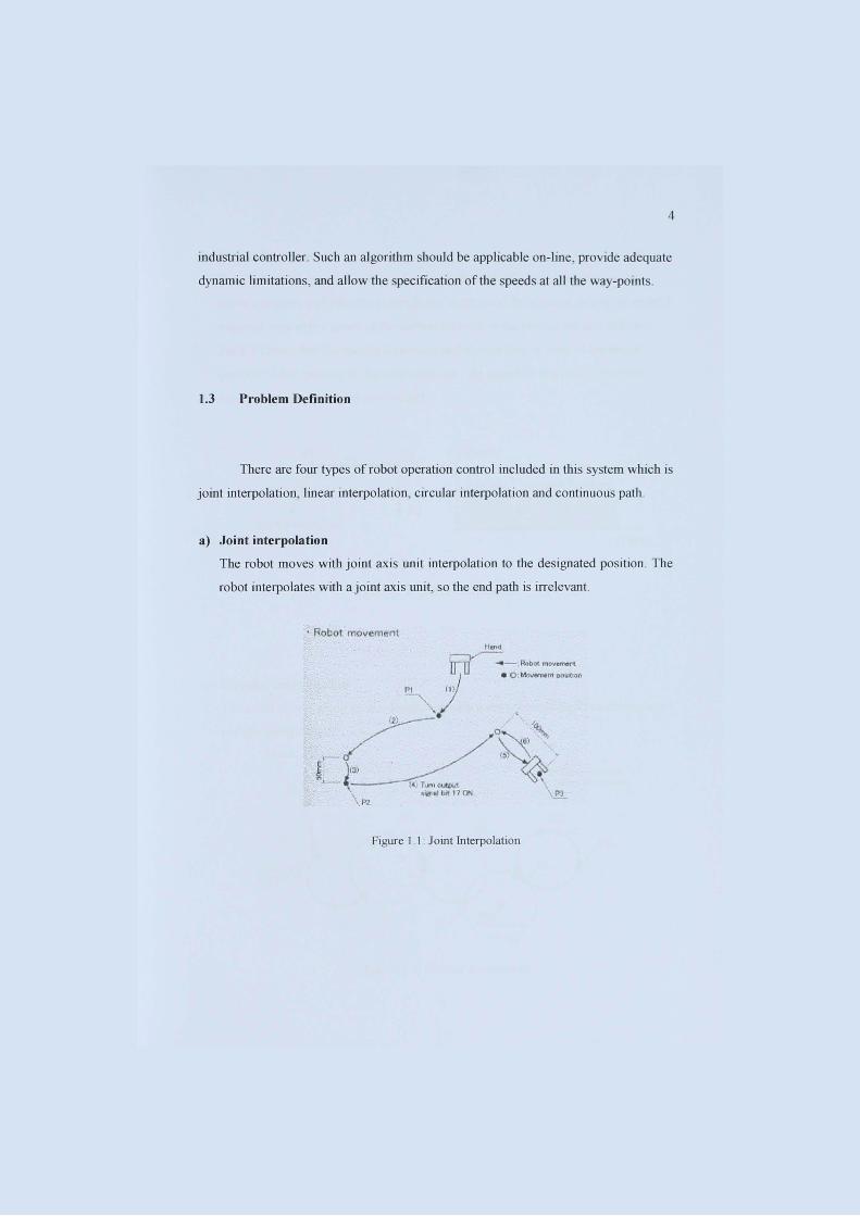
a) Joint interpolation
The robot moves with joint axis lmit interpolation to the designated position. The
robot interpolates with ajoint axis unit, so the end path is irrelevant.
. Robot movement
Figure 1.1' Joint Interpolation
5
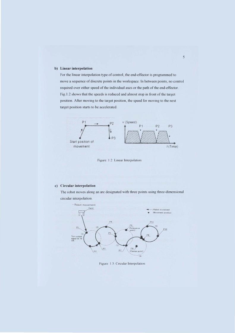
b) Linear interpolation
For the linear interpolation type of control, the end-effector is programmed to
move a sequence of discrete points in the workspace. In between points, no control
required over either speed of the individual axes or the path of the end-effector.
Fig.l .2 shows that the speeds is reduced and almost stop in front of the target
position . After moving to the target position, the speed for moving to the next
target position starts to be accelerated .
Sia.rt paslhon af mOVemen
c) Circular interpolation
II (Speed)
f f77777A~1 P2 P3
rilU4 . I (TIm!!)
Figure: 1.2: Linear Interpolation
The robot moves along an arc designated with three points using three-dimensional
circuJar interpolation .
• Robot movement
T\)f'~ outPut IIlMit.it I B Oil
Figure. 1.3. Circular Interpolation
~ Robot- mo .... ment • Moyement p05ftion
PI!
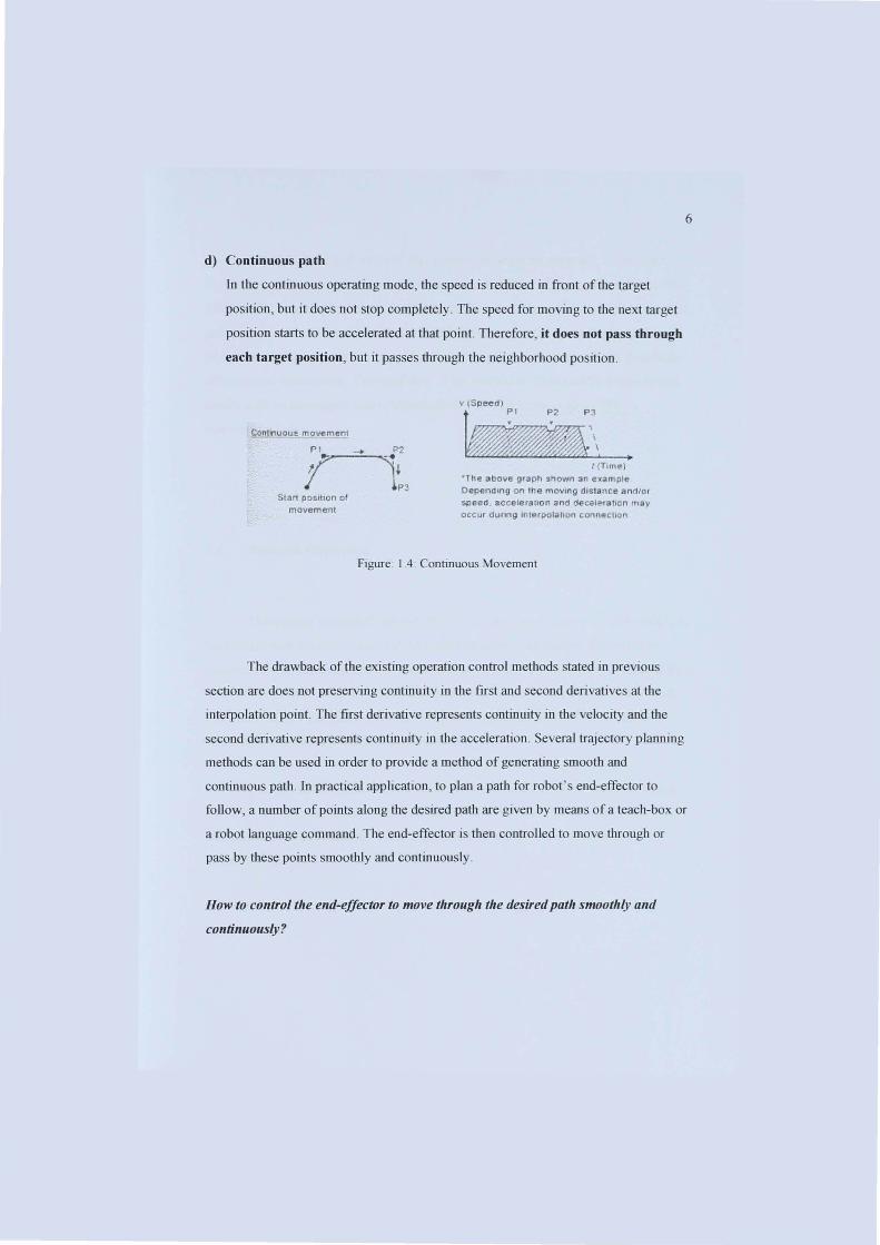
d) Continuous path
In the continuous operating mode, the speed is reduced in front of the target
position, but it does not stop completely. The speed for moving to the next target
position starts to be accelerated at that point. Therefore, it does not pass through
each target position, but it passes through the neighborhood position.
Contlnuau~ movemelJj
P I -0- 1>2
J'~~ ,jI lp3
SIll rt ~ osition of movEtmet1t
v (Speed;' PI P2 PJ
I (Tlmel ·The abo~o; g,apll snown an example OependU19 on ll1e movIng dIstance and/or $Plled . "cceleratlon and (ieeel"" \Ion may occ ur dunng Interpotatlon connecllon
Figure: 1.4: Continuous Movement
6
The drawback of the existing operation control methods stated in previous
section are does not preserving continuity in the first and second derivatives at the
interpolation point. The first derivative represents continuity in the velocity and the
second derivative represents continuity in the acceleration. Several trajectory planning
methods can be used in order to provide a method of generating smooth and
continuous path. In practical application , to plan a path for robot's end-effector to
follow, a number of points along the desired path are given by means of a teach-box or
a robot language command. The end-effector is then controlled to move through or
pass by these points smoothly and continuously.
How to control tile end-effector to move tllrougll tile desired patll smoothly and
continuously?
To solve the stated problem, this project proposed an approach to constrain
smoothness and continuity based on cubic spline trajectory planning algorithm. Cubic
splines offer several advantages. First, it is the lowest degree polynomial function that
preserving continuity in the first and second derivatives at the interpolation points.
Second, low-degree polynomials reduce the effort of computations and the possibility
of numerical instabilities. The feasibility of the method is illustrated by experimental
results with an articulated robot (Mitsubishi RV-2AJ) located at KUITTHO's
Automation Lab.
1.4 Research Objectives
7
This project is divided into two parts. For Part I, the objective of this work is to
familiarize with the Mitsubishi RV-2AJ robot operation and control. Instead of to
familiarize with the robot operation and control, a further objective is to produce a set
oflaboratory sheets as a reference material to the students or lecturers in future work.
Furthermore is to learn MELFA robot programming languages, MOVE MASTER
Command and MELFA-BASIV IV Command.
For Part II, the objective is to write a user-defined trajectory planning routine
based on cubic spline fitting function using MATLAB. At the end of this project, this
work aims to produce a cubic spline trajectory that will generate smooth and
continuous path.

CHAPTER II
LITERATURE REVIEW
2.1 Introduction
With a pressing need for increased productivity and the delivery of end
products of uniform quality, industry is turning more and more toward computcr
based automation. At the present time, most automated manufacturing tasks are
carried out by special-purpose machines designed to perfonn predeterrnined functions
in a manufacturing process. The innexibility and generally high cost of these
machines, often called hard automation systems, have led to a broad-based jnterest jn
the use of robots capable of performing a variety of manufacturing functions in a more
nexible working environment and at lower production costs.
The word robot originated from the Czech word roho{(], meaning work.
Webster's dictionary defines robot as "an automatic dC\'ice that performs functions
ordinarily ascribed to human being." Vhth this definition, washing machines rnay h<.:
considercd robots. A definition used by the Robot Institute of America gi\<.:s a flwr<.:
precise description of industrial robots: "A robot is a rcprogrammable mull i-functional