Embed Size (px)
Citation preview

NRPG RENAL CLINIC - THE DALLES
PERMIT SETPROJECT MANUAL
MAY 29, 2012

PROJECT NRPG Renal Clinic – The Dalles 411 Lone Pine Blvd. The Dalles, Oregon OWNER Northwest Renal Property Group (NRPG) 3730 SW Shattuck Rd. Portland, OR 97221 Phone: (503) 849-4087 Owner’s Representative: Wayne Armstrong e-mail: [email protected] ARCHITECT Stack Architecture 32 NE 7th Ave. Portland, OR 97232 Phone: (503) 481-1332 Fax: (503) 296-2688 Principal: Chris Spurgin, AIA, LEED AP e-mail: [email protected] Principal: Francis B. Dardis, AIA e-mail: [email protected] GENERAL CONTRACTOR Yorke & Curtis 4480 SW 101st Ave. Portland, OR 97005 Phone: (503) 646-2123 Fax: (503) 643-5531 Proj. Mgr.: Dave Curtis e-mail: [email protected] Architect's Project Number: 11036 Date: June 4, 2012

TOC-1
TABLE OF CONTENTS This Project Manual has been organized under the format of the Construction Specifications Institute (CSI). Section numbers are listed merely for identification, and they may not be consecutive. The Contractor shall check the contents of this Manual against the Table of Contents to assure that this volume is complete. BIDDING REQUIREMENTS 00200 Instructions to Bidders 00320 Geotechnical Data CONTRACTING REQUIREMENTS 00500 Form of Agreement 00700 General Conditions 00800 Supplementary Conditions 00930 Requests for Interpretations DIVISION 1 - GENERAL REQUIREMENTS 01110 Summary of Work 01115 Design-Build Requirements 01200 Base Bid & Alternate Bids 01250 Change Order Procedures 01290 Schedule of Values 01295 Applications for Payment 01310 Project Coordination 01312 Digital Data Transmission 01315 Project Meetings 01320 Progress Schedules 01330 Shop Drawings, Product Data, & Samples 01420 Referenced Specifications & Standards 01450 Contractor's Quality Control Program 01453 Testing Laboratory Services 01500 Temporary Construction Facilities 01565 Project Security 01600 Materials & Equipment 01630 Product Substitutions 01640 Materials Recycling & Waste Management 01720 Field Engineering 01730 Cutting & Patching 01740 Cleaning & Trash Removal 01750 Equipment & Systems Start Up 01770 Contract Closeout 01780 Warranties & Bonds 01820 Project Record Documents 01830 Operating & Maintenance Data
TOC-2
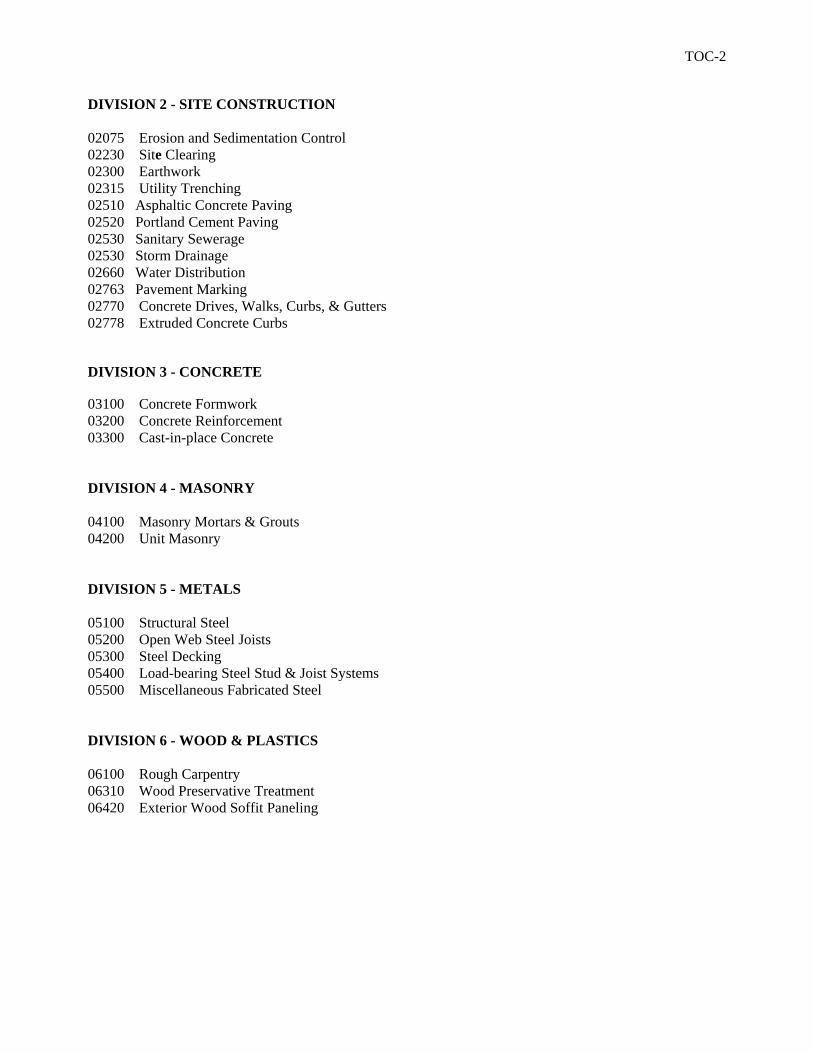
DIVISION 2 - SITE CONSTRUCTION 02075 Erosion and Sedimentation Control 02230 Site Clearing 02300 Earthwork 02315 Utility Trenching 02510 Asphaltic Concrete Paving 02520 Portland Cement Paving 02530 Sanitary Sewerage 02530 Storm Drainage 02660 Water Distribution 02763 Pavement Marking 02770 Concrete Drives, Walks, Curbs, & Gutters 02778 Extruded Concrete Curbs DIVISION 3 - CONCRETE 03100 Concrete Formwork 03200 Concrete Reinforcement 03300 Cast-in-place Concrete DIVISION 4 - MASONRY 04100 Masonry Mortars & Grouts 04200 Unit Masonry DIVISION 5 - METALS 05100 Structural Steel 05200 Open Web Steel Joists 05300 Steel Decking 05400 Load-bearing Steel Stud & Joist Systems 05500 Miscellaneous Fabricated Steel DIVISION 6 - WOOD & PLASTICS 06100 Rough Carpentry 06310 Wood Preservative Treatment 06420 Exterior Wood Soffit Paneling
TOC-3
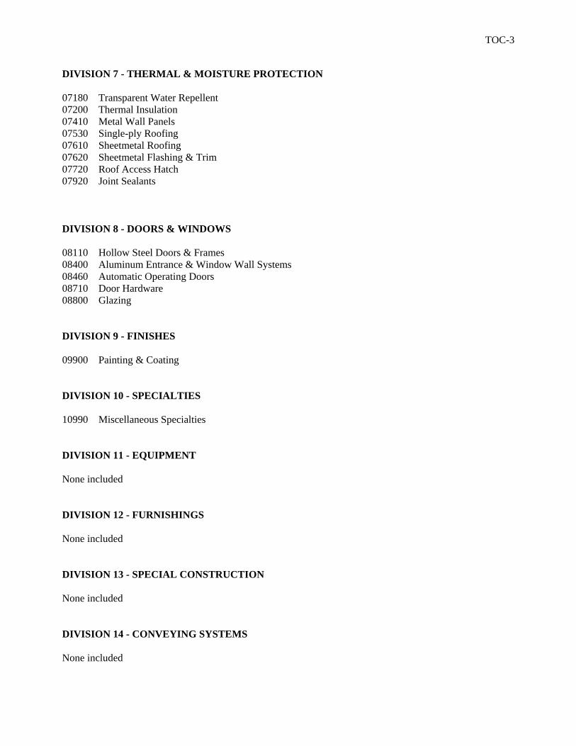
DIVISION 7 - THERMAL & MOISTURE PROTECTION 07180 Transparent Water Repellent 07200 Thermal Insulation 07410 Metal Wall Panels 07530 Single-ply Roofing 07610 Sheetmetal Roofing 07620 Sheetmetal Flashing & Trim 07720 Roof Access Hatch 07920 Joint Sealants DIVISION 8 - DOORS & WINDOWS 08110 Hollow Steel Doors & Frames 08400 Aluminum Entrance & Window Wall Systems 08460 Automatic Operating Doors 08710 Door Hardware 08800 Glazing DIVISION 9 - FINISHES 09900 Painting & Coating DIVISION 10 - SPECIALTIES 10990 Miscellaneous Specialties DIVISION 11 - EQUIPMENT None included DIVISION 12 - FURNISHINGS None included DIVISION 13 - SPECIAL CONSTRUCTION None included DIVISION 14 - CONVEYING SYSTEMS None included

TOC-4
DIVISION 15 - MECHANICAL 15010 General Provisions 15050 Basic Mechanical Materials & Methods 15060 Hangers & Supports for HVAC Piping and Equipment 15074 Vibration & Seismic Controls for HVAC Piping & Equipment 15300 Fire Protection 15400 Plumbing DIVISION 26 - ELECTRICAL 260500 Common Work Results for Electrical 260519 Low Voltage Electrical Power Conductors and Cables 260526 Grounding and Bonding for Electrical Systems 260529 Hangers and Supports for Electrical Systems 260533 Raceways and Boxes for Electrical Systems 260553 Identification for Electrical Systems 262413 Switchboards 262726 Wiring Devices 265000 Lighting DIVISION 32 – EXTERIOR IMPROVEMENTS 328400 Irrigation 329300 Planting SCHEDULES Material/Color Schedule Door Schedule Door Profiles Hardware Schedule
END OF TABLE

SECTION 00200 00200-1 INSTRUCTIONS TO BIDDERS
NRPG RENAL CLINIC - THE DALLES 00200-1
1 • DEFINITIONS 2 3 • Bidding Documents include the Bidding Requirements and the proposed Contract 4
Documents. The Bidding Requirements consist of the Instructions to Bidders, and other 5 sample Bidding and Contract Forms. The proposed Contract Documents consist of 6 the Form of Agreement between the Owner and the Contractor, Conditions of the 7 Contract (General, Supplementary, and other Conditions), Drawings, Specifications, 8 and all Addenda issued prior to the execution of the Contract. 9
• All definitions set forth in the Contract General Conditions, or in other Contract 10 Documents, are applicable to the Bidding Documents. 11
• Addenda: Written or Graphic instruments issued by the Architect prior to the 12 execution of the Contract which modify, clarify, or interpret the Bidding Documents by 13 additions, deletions, or corrections. 14
• The Base Bid is the sum stated in the Bid for which the Bidder offers to perform the 15 Work described in the Bidding Documents as the base to which Work may be added, or 16 from which Work may be deducted for sums stated in Alternate Bids. 17
• An Alternate Bid (or Alternate) is an amount stated in the Bid to be added to or 18 deducted from the amount of the Base Bid if the corresponding change in the Work, as 19 described in the Bidding Documents, is accepted. 20
• Where a Bidder is referred to in this Section, it shall mean the General Contractor who 21 has been selected by the Owner to perform the Work. 22
• Where Subbidders are referred to in this Section, they shall mean the Subcontractors 23 who have been selected by the General Contractor to provide materials, equipment, 24 and/or labor for a portion of the Work. 25
26 27 • BIDDER'S REPRESENTATION 28 29 • The Bidder, by submitting a Bid, represents that: 30
• The Bidder has read and understands the Bidding Documents and the Bid is 31 made in accordance therewith. 32
• The Bidder has visited the Site, become familiar with local conditions under 33 which the Work is to be performed and has correlated the Bidder's personal 34 observations with the requirements of the proposed Contract Documents. 35
• The Bid is based upon the Materials, Equipment, and Systems required by the 36 Bidding Documents without exception. 37
38 39 • BIDDING DOCUMENTS 40 41 • Copies: 42
• Complete sets of Bidding Documents shall be used in preparing Bids; neither 43 the Owner nor the Architect assumes any responsibility for errors or 44 misinterpretations resulting from the use of incomplete sets of Bidding 45 Documents. 46
47 (Cont.) 48

SECTION 00200 00200-2 INSTRUCTIONS TO BIDDERS
NRPG RENAL CLINIC - THE DALLES 00200-2
1 • BIDDING DOCUMENTS (Cont.) 2 3 • Copies: (Cont.) 4
• In making copies of the Bidding Documents available on the above terms, the 5 Owner and the Architect do so only for the purpose of obtaining Bids on the 6 Work and do not confer a license or grant permission for any other use of the 7 Bidding Documents. 8
• Interpretation or Correction of Bidding Documents: 9 • Bidders and Subbidders shall carefully study and compare the Bidding Documents 10
with each other and with other work being bid concurrently or presently underway 11 to the extent that it relates to the Work for which the Bid is submitted, shall 12 examine the site and local conditions, and shall promptly notify the Architect of 13 any ambiguity, inconsistency, or error which they may discover. 14
• Bidders and Subbidders requiring clarification or interpretation of the Bidding 15 Documents shall make a request to reach the Architect at least seven days prior 16 to the date for receipt of Bids. 17
• Any interpretation, correction, or change of the Bidding Documents will be 18 made by Addendum. Interpretations, corrections, or changes of the Bidding 19 Documents made in any other manner will not be binding, and Bidders shall not 20 rely upon such interpretations, corrections, and changes. 21
• Product Substitutions: 22 • Submit requests for approval in accordance with requirements specified in 23
Section 01630, and to reach Architect at least 5 Working Days prior to Subbid 24 submission dates. 25
• Addenda: 26 • Copies of Addenda will be made available for inspection wherever Bidding 27
Documents are on file for that purpose, and will be issued as follows: 28 • Addenda will be postal-mailed, electronically-mailed, or telephone-29
facsimiled (faxed) to each Entity who filed name, postal-address, e-mail 30 address, or telephone facsimile (fax) number with the General 31 Contractor for the express purpose of receiving Addenda. 32
• Telephoned Addenda will not be assumed to be reliable transmissions. 33 • Bidder shall ascertain, prior to submitting a Bid, that the Bidder, and each 34
Subbidder, has received all Addenda issued, and the Bidder shall acknowledge 35 receipt of the Addenda in the Bid. 36
• Addenda, if any, issued after Subbid submissions, will be transmitted only to 37 Subbidders whose Subbid is under consideration, and adequate time will be 38 allowed for response thereto. 39
40 41 42 43 44
(Cont.) 45 46 47 48
SECTION 00200 00200-3 INSTRUCTIONS TO BIDDERS
NRPG RENAL CLINIC - THE DALLES 00200-3
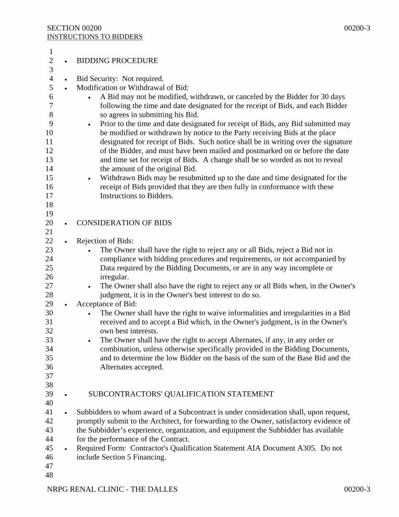
1 • BIDDING PROCEDURE 2 3 • Bid Security: Not required. 4 • Modification or Withdrawal of Bid: 5
• A Bid may not be modified, withdrawn, or canceled by the Bidder for 30 days 6 following the time and date designated for the receipt of Bids, and each Bidder 7 so agrees in submitting his Bid. 8
• Prior to the time and date designated for receipt of Bids, any Bid submitted may 9 be modified or withdrawn by notice to the Party receiving Bids at the place 10 designated for receipt of Bids. Such notice shall be in writing over the signature 11 of the Bidder, and must have been mailed and postmarked on or before the date 12 and time set for receipt of Bids. A change shall be so worded as not to reveal 13 the amount of the original Bid. 14
• Withdrawn Bids may be resubmitted up to the date and time designated for the 15 receipt of Bids provided that they are then fully in conformance with these 16 Instructions to Bidders. 17
18 19 • CONSIDERATION OF BIDS 20 21 • Rejection of Bids: 22
• The Owner shall have the right to reject any or all Bids, reject a Bid not in 23 compliance with bidding procedures and requirements, or not accompanied by 24 Data required by the Bidding Documents, or are in any way incomplete or 25 irregular. 26
• The Owner shall also have the right to reject any or all Bids when, in the Owner's 27 judgment, it is in the Owner's best interest to do so. 28
• Acceptance of Bid: 29 • The Owner shall have the right to waive informalities and irregularities in a Bid 30
received and to accept a Bid which, in the Owner's judgment, is in the Owner's 31 own best interests. 32
• The Owner shall have the right to accept Alternates, if any, in any order or 33 combination, unless otherwise specifically provided in the Bidding Documents, 34 and to determine the low Bidder on the basis of the sum of the Base Bid and the 35 Alternates accepted. 36
37 38 • SUBCONTRACTORS' QUALIFICATION STATEMENT 39 40 • Subbidders to whom award of a Subcontract is under consideration shall, upon request, 41
promptly submit to the Architect, for forwarding to the Owner, satisfactory evidence of 42 the Subbidder’s experience, organization, and equipment the Subbidder has available 43 for the performance of the Contract. 44
• Required Form: Contractor's Qualification Statement AIA Document A305. Do not 45 include Section 5 Financing. 46
47 48
SECTION 00200 00200-4 INSTRUCTIONS TO BIDDERS
NRPG RENAL CLINIC - THE DALLES 00200-4
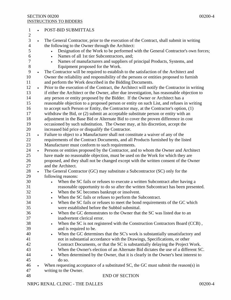
• POST-BID SUBMITTALS 1 2 • The General Contractor, prior to the execution of the Contract, shall submit in writing 3
the following to the Owner through the Architect: 4 • Designation of the Work to be performed with the General Contractor's own forces; 5 • Names of all 1st tier Subcontractors, and; 6 • Names of manufacturers and suppliers of principal Products, Systems, and 7
Equipment proposed for the Work. 8 • The Contractor will be required to establish to the satisfaction of the Architect and 9
Owner the reliability and responsibility of the persons or entities proposed to furnish 10 and perform the Work described in the Bidding Documents. 11
• Prior to the execution of the Contract, the Architect will notify the Contractor in writing 12 if either the Architect or the Owner, after due investigation, has reasonable objection to 13 any person or entity proposed by the Bidder. If the Owner or Architect has a 14 reasonable objection to a proposed person or entity on such List, and refuses in writing 15 to accept such Person or Entity, the Contractor may, at the Contractor's option, (1) 16 withdraw the Bid, or (2) submit an acceptable substitute person or entity with an 17 adjustment in the Base Bid or Alternate Bid to cover the proven difference in cost 18 occasioned by such substitution. The Owner may, at his discretion, accept the 19 increased bid price or disqualify the Contractor. 20
• Failure to object to a Manufacturer shall not constitute a waiver of any of the 21 requirements of the Contract Documents, and all Products furnished by the listed 22 Manufacturer must conform to such requirements. 23
• Persons or entities proposed by the Contractor, and to whom the Owner and Architect 24 have made no reasonable objection, must be used on the Work for which they are 25 proposed, and they shall not be changed except with the written consent of the Owner 26 and the Architect. 27
• The General Contractor (GC) may substitute a Subcontractor (SC) only for the 28 following reasons: 29
• When the SC fails or refuses to execute a written Subcontract after having a 30 reasonable opportunity to do so after the written Subcontract has been presented. 31
• When the SC becomes bankrupt or insolvent. 32 • When the SC fails or refuses to perform the Subcontract. 33 • When the SC fails or refuses to meet the bond requirements of the GC which 34
were established before the Subbid submittal. 35 • When the GC demonstrates to the Owner that the SC was listed due to an 36
inadvertent clerical error. 37 • When the SC is not registered with the Construction Contractors Board (CCB) , 38
and is required to be. 39 • When the GC determines that the SC's work is substantially unsatisfactory and 40
not in substantial accordance with the Drawings, Specifications, or other 41 Contract Documents, or that the SC is substantially delaying the Project Work. 42
• When the Owner's election of an Alternate Bid dictates the use of a different SC. 43 • When determined by the Owner, that it is clearly in the Owner's best interest to 44
do so. 45 • When requesting acceptance of a substituted SC, the GC must submit the reason(s) in 46
writing to the Owner. 47 END OF SECTION 48

SECTION 00320 00320-1 GEOTECHNICAL DATA
NRPG RENAL CLINIC - THE DALLES 00320-1
1 • SUB-SURFACE SOIL INVESTIGATION REPORTS 2 3 • The following Reports are available for review and reference: 4
• Building B – Lone Pine Village Development – The Dalles, Oregon 5 • Dated: Nov. 15, 2010 6 • Geotechnical Engineer: 7
• Firm Name: RhinoOne Geotechnical 8 • Address: 1308 Main St.; Vancouver, WA 98660 9 • Telephone Number: (360) 200-6928 10
• Lone Pine Village PUD – The Dalles, Oregon 11 • Dated: March 2, 2007 12 • Geotechnical Engineer: 13
• Firm Name: PBS 14 • Address: 1310 Main St.; Vancouver, WA 98660 15 • Telephone Number: (360) 690-4331 16
• Reports can be reviewed at the following locations: 17 • Geotechnical Engineer's Office 18 • Architect's Office 19 • Contractor's Office 20
21 22 • OWNER'S DISCLAIMER 23 24 • The Reports are not part of the Contract Documents. They are made available for 25
information only. 26 • The Owner does not guarantee Report Information accuracy at locations and times 27
other than those given. Groundwater elevations, particularly, are subject to change. 28 • The Contractor shall assume responsibility for any conclusions the Contractor may 29
draw from these Reports. The Contractor may employ its own consultants to analyze 30 this information and/or conduct additional tests and examinations. 31
• The Owner specifically disclaims responsibility for interpretations by any Bidder of 32 information included within the Reports. 33
34 35 • DIFFERENT CONDITIONS 36 37 • If, during construction, conditions are encountered which differ substantially from 38
those indicated in these Reports, promptly so notify the Architect in writing, and do not 39 disturb such conditions until directed. 40
• The Architect will promptly request the Owner to instruct the Geotechnical Engineer to 41 investigate such conditions. 42
• If the Geotechnical Engineer determines that conditions do differ substantially from those 43 that reasonably could be anticipated from examination of the Site and the Report, and that 44 such conditions will necessitate a change in the Work and/or an adjustment of the Contract 45 Sum and/or the Contract Time, the Owner will authorize a Change Order, as stipulated in the 46 General Conditions, to enable the necessary changes and/or adjustments. 47
END OF SECTION 48

SECTION 00500 00500-1 FORM OF AGREEMENT
NRPG RENAL CLINIC - THE DALLES 00500-1
1 • FORM OF AGREEMENT 2 3 • The Agreement between the Owner and the Contractor for the Work of this Project will 4
be executed on AIA Document A102 - Cost of the Work plus a Fee with a Guaranteed 5 Maximum Price. 6
• An example of the Agreement may be examined at the Architect's Office, and copies 7 can be ordered from: 8
• Portland Chapter AIA; 403 NW 11th Ave; Portland, OR 97209; (503) 223-8757 9 • American Institute of Architects; Box 60; Williston, VT 05495; (800) 365-2724 10
• Additionally, Document can be ordered from American Institute of Architects at: 11 • http://documentsondemand.aia.org/ 12
13 14 15 16
END OF SECTION 17 18 19 20 21 22 23 24 25 26 27 28 29 30 31 32 33 34 35 36 37 38 39 40 41 42 43 44 45 46 47 48

SECTION 00700 00700-1 GENERAL CONDITIONS
NRPG RENAL CLINIC - THE DALLES 00700-1
1 • STANDARD FORM 2 3 • "General Conditions of the Contract for Construction", AIA Document A201, 2007 4
edition, is hereby made part of these Specifications as fully as if hereto attached or 5 herein repeated. 6
• The Contractor and all Subcontractors shall read and be governed by them. 7 • Copies of the General Conditions may be seen at the Architect's office, and copies can 8
be ordered from: 9 • Portland Chapter AIA; 403 NW 11th Ave; Portland, OR 97209; (503) 223-8757 10 • American Institute of Architects; Box 60; Williston, VT 05495; (800) 365-2724 11
• Additionally, Document can be ordered from American Institute of Architects at: 12 • http://documentsondemand.aia.org/ 13
14 15 16 17 18
END OF SECTION 19 20 21 22 23 24 25 26 27 28 29 30 31 32 33 34 35 36 37 38 39 40 41 42 43 44 45 46 47 48

SECTION 00800 00800-1 SUPPLEMENTARY GENERAL CONDITIONS
NRPG RENAL CLINIC - THE DALLES 00800-1
1 • GENERAL 2 3 • The following Supplements modify the General Conditions. Where a portion of the 4
General Conditions is modified or deleted by these Supplementary Conditions, the 5 unaltered provisions of the General Conditions shall remain in effect. 6
7 8 • CONTRACT DOCUMENTS 9 10 • Article 1.1.1.1 shall be added as follows: 11
• The Contract Drawings are identified on the Cover Sheet of the Drawings. 12 • Article 1.1.1.2 shall be added as follows: 13
• The Contract Documents executed in accordance with Article 1.5.1 shall prevail 14 in case of an inconsistency with subsequent versions made through 15 manipulatable electronic operations involving computers. 16
17 18 • SPECIFICATIONS DIVISION, SECTION, & PARAGRAPH NUMBERING 19 20 • Article 1.1.6 shall be added to as follows: 21
• Numbering or lettering of Divisions, Sections, and Paragraphs in the 22 Specifications are merely for identification and may not be consecutive. 23
• The Divisions and Sections included are listed in the Table of Contents. The 24 Contractor shall verify that the Contractor’s copies of the Project Manual are 25 complete. 26
27 28 • SPECIFICATIONS WORDING 29 30 • Article 1.1.6 shall be added to as follows: 31
• The Specifications are of abbreviated or streamlined type and frequently include 32 incomplete sentences. Words such as "shall", "shall be", "Contractor shall", and 33 similar mandatory phrases shall be supplied by inference in same manner as 34 they are in a note on Drawings. Contractor shall provide all Items listed and 35 perform all operations required, in accordance with Article 1.1.2 of "General 36 Conditions," if and as modified in these Specifications. 37
• In the interest of brevity the Contract Documents frequently omit modifying 38 words such as "all", "each", and "every" and articles such as "the", "a", and 39 "an", but the fact that a modifier or an article is absent from one statement and 40 appears in another is not intended to affect the interpretation of either statement. 41
42 43 44 45 46
(Cont.) 47 48

SECTION 00800 00800-2 SUPPLEMENTARY GENERAL CONDITIONS
NRPG RENAL CLINIC - THE DALLES 00800-2
• SPECIFICATIONS DEFINITIONS 1 2 • Article 1.1.6 shall be added to as follows: 3
• "Directed", "Requested", "Approved", "Authorized", "Selected", 4 "Required", and "Permitted" mean directed by the Architect, requested by the 5 Architect, etc. 6
• "Furnish" means to supply and deliver to the Project Site, ready for unloading, 7 unpacking, assembly, installation, and similar operations. 8
• "Indicated" means references to graphic representations; notes or schedules on 9 the Drawings, or other paragraphs or schedules in the Specifications; and similar 10 requirements in the Contract Documents. Terms such as "shown", "noted", 11 "scheduled", and "specified" are used to help the User locate the Reference. 12
• "Install" means operations at the Project Site including actual unloading, 13 temporary storing, unpacking, assembling, erecting, placing, anchoring, 14 applying, working to dimension, finishing, curing, protecting, cleaning, and 15 similar operations. 16
• "OFOI" (Owner Furnished & Owner Installed) means Product in question 17 will be furnished and installed by the Owner. The Contractor shall verify all 18 requirements affecting his Work. 19
• "OFCI" (Owner Furnished & Contractor Installed) means Product in 20 question will be furnished by the Owner, and installed by the Contractor. The 21 Contractor shall verify all requirements affecting his Work. 22
23 24
• CONFLICTS 25 26 • Article 1.2.1.1 shall be added as follows: 27
• In the event of conflict or discrepancy among the Contract Documents, 28 interpretations will be based on the following priorities: 29
• Contract amendments, Addenda, and Change Orders with those of later 30 date having precedence over those of earlier date. 31
• Agreement 32 • Supplementary General Conditions of the Contract for Construction 33 • General Conditions of the Contract for Construction 34 • Division 1 of the Specifications 35 • Schedules 36 • Drawings & Specifications 37
• In the event of conflicts or discrepancies between the Drawings 38 and the Specifications or within either Document not clarified by 39 Addendum, the better quality or greater quantity of Work shall 40 be provided in accordance with the Architect's interpretation, 41 except where there exists an obvious error, in which case the 42 Contractor shall request the Architect's interpretation and execute 43 the Work as directed. 44
• Large Scale Drawings 45 • Small Scale Drawings 46 • Dimension Numbers written on Drawings prevail and take precedence 47
over Dimensions scaled from Drawings 48

SECTION 00800 00800-3 SUPPLEMENTARY GENERAL CONDITIONS
NRPG RENAL CLINIC - THE DALLES 00800-3
1 • CONTRACTOR'S USE OF CONTRACT DOCUMENTS IN ELECTRONIC FORM 2 3 • Article 1.6.1 shall be added as follows: 4
• The Architect may furnish to the Contractor versions of the Instruments of 5 Service in electronic form. The Contract Documents executed or identified in 6 accordance with Subparagraph 1.5.1 shall prevail in case of an inconsistency 7 with subsequent versions made through manipulatable electronic means 8 involving computers. 9
• The Contractor shall not transfer or reuse Instruments of Service in electronic or 10 machine readable form without prior written consent of the Architect. 11
• Additionally, comply with requirements specified in Section 01312. 12 13 14 • ALTERING RESPONSIBILITIES OF OWNER, ARCHITECT, OR CONTRACTOR 15 16 • Articles 2, 3, & 4 shall be added to as follows: 17
• No provision in any referenced Standard, Specification, Manual, or Code 18 (whether or not specifically incorporated by reference in the Contract 19 Documents) shall be effective to change the privileges, duties, or 20 responsibilities of the Owner, Architect, or Contractor, or any of their 21 consultants, agents, or employees from those set forth in the Contract 22 Documents, nor shall it be effective to assign to the Architect or any of the 23 Architect's consultants, agents, or employees any duty or authority to supervise 24 or direct the furnishing or performance of the Work or any duty or authority to 25 undertake responsibility contrary to the provision of the Contract Documents. 26
27 28 • SUB-SURFACE DATA 29 30 • Article 2.2.3 shall be added to as follows: 31
• Additionally, follow requirements specified in Section 00320. 32 33 34 • SPECIAL TESTS & INSPECTIONS 35 36 • Article 2.2.6 shall be added as follows: 37
• The Owner will procure and bear costs of Structural Tests and Special 38 Inspections as required by the Building Code. 39
40 41 42 43 44
(Cont.) 45 46 47 48
SECTION 00800 00800-4 SUPPLEMENTARY GENERAL CONDITIONS
NRPG RENAL CLINIC - THE DALLES 00800-4
1 • OWNER'S RIGHT TO PAY CLAIMS AGAINST CONTRACTOR 2 3 • Article 2.5 shall be added as follows: 4
• If the Contractor fails, neglects, or refuses to make prompt payment of any 5 claim for labor or services furnished to the Contractor or any Subcontractor by 6 any person in connection with this Contract as such claim becomes due, the 7 Owner may pay such claim to the person furnishing such labor or services, and 8 charge the amount of the payment against funds due, or to become due, to the 9 Contractor by reason of this Contract. 10
• The Owner's payment of such claim will not relieve the Contractor or the 11 Contractor's Surety, if any, from the Contractor's obligation with respect to any 12 unpaid claims. 13
14 15 • CONTRACTORS' REGISTRATION 16 17 • Article 3.1.1.1 shall be added as follows: 18
• The Contractor and each Subcontractor shall possess and maintain for the 19 duration of the Project a registration with the Construction Contractors Board or 20 the State Landscape Contractors Board in accordance with the laws of the State 21 of Oregon and the Contractor shall submit evidence of such registration prior to 22 executing the Contract. 23
• Plumbing, Boiler, and Electrical Workers, if any, must visibly display their 24 State Licenses while working on Project Site. Licenses may be concealed 25 within Worker's Pocket if and when working in dangerous areas. 26
27 28 • INAPPROPRIATE PRODUCTS OR METHODS 29 30 • Article 3.2.1 shall be added to as follows: 31
• If the Contractor or any Subcontractor believes that inappropriate Products or 32 Methods have been specified, they shall comply with requirements specified in 33 Section 01600. 34
35 36 • CONTRACTOR'S REQUESTS FOR INFORMATION 37 38 • Article 3.2.5 shall be added as follows: 39
• The Owner shall be entitled to deduct from the Contract Sum amounts paid by 40 the Owner to the Architect for the Architect to evaluate and respond to the 41 Contractor's requests for information, where such information was available to 42 the Contractor from a careful study and comparison of the Contract Documents, 43 field conditions, other Owner-provided information, Contractor-prepared 44 coordination drawings, or prior Project correspondence or documentation. 45
• Additionally, comply with requirements specified in Section 00930. 46 47 48

SECTION 00800 00800-5 SUPPLEMENTARY GENERAL CONDITIONS
NRPG RENAL CLINIC - THE DALLES 00800-5
1 • FIELD ENGINEERING 2 3 • Article 3.3.4 shall be added as follows: 4
• Comply with requirements specified in Section 01720. 5 6 7 • LISTING PRODUCT MANUFACTURERS & INSTALLERS 8 9 • Article 3.4.4 shall be added as follows: 10
• Comply with requirements specified in Section 01600. 11 12 13 • PRODUCT SUBSTITUTIONS 14 15 • Article 3.4.5 shall be added as follows: 16
• Comply with requirements specified in Section 01630. 17 18 19 • PERMITS 20 21 • Article 3.7.1 shall be modified as follows: 22
• The General Building Permit shall be secured and paid for by the Contractor. 23 The cost of the Fee, however, will be reimbursed by the Owner, and therefore 24 the Contractor shall not include the Fee in the Contract Sum. 25
• The Plan Checking Fees have been paid by the Owner, and therefore the 26 Contractor shall not include the Fees in the Contract Sum. 27
• Systems Development Charges, if any, will be paid by the Owner, and therefore 28 the Contractor shall not include the Charges in the Contract Sum. 29
• All other legally required Permits and Licenses shall be obtained and their Fees 30 paid for by the Contractor. 31
32 33 • CONTRACTOR'S SUPERINTENDENT 34 35 • Article 3.9.1 shall be added to as follows: 36
• The Superintendent shall not be replaced without the written consent of the 37 Owner and the Architect, and the Contractor shall be responsible for any 38 additional costs caused by such replacement. 39
40 (Cont.) 41
42 43 44 45 46 47 48

SECTION 00800 00800-6 SUPPLEMENTARY GENERAL CONDITIONS
NRPG RENAL CLINIC - THE DALLES 00800-6
1 • CONTRACTOR'S SUPERINTENDENT (Cont.) 2
3 • Article 3.9.2 shall be added as follows: 4
• The Contractor shall employ a Superintendent or an assistant to the 5 Superintendent who will perform as a Coordinator for mechanical and electrical 6 Work. The Coordinator shall be knowledgeable in mechanical and electrical 7 systems and capable of reading, interpreting and coordinating Drawings, 8 Specifications, and shop drawings pertaining to such systems. The Coordinator 9 shall assist the Subcontractors in arranging space conditions to eliminate 10 interference between the mechanical and electrical systems and other Work and 11 shall supervise the preparation of coordination drawings documenting the 12 spatial arrangements for such systems within restricted spaces. The Coordinator 13 shall assist in planning and expediting the proper sequence of delivery of 14 mechanical and electrical equipment to the site. 15
16 17 • PROGRESS SCHEDULE 18 19 • Article 3.10.1 shall be added to as follows: 20
• Additionally, follow requirements specified in Section 01320. 21 22 23 • SHOP DRAWINGS, PRODUCT DATA, & SAMPLES 24 25 • Article 3.12.11 shall be added as follows: 26
• The Architect's review of Contractor's submittals will be limited to examination 27 of an initial submittal and one resubmittal. The Architect's review of additional 28 resubmittals will be made only with the consent of the Owner after notification 29 by the Architect. The Owner shall be entitled to deduct from the Contract Sum 30 amounts paid to the Architect for evaluation of such additional resubmittals. 31
• Article 3.12.12 shall be added as follows: 32 • Additionally, follow requirements specified in Section 01330. 33
34 35 • CUTTING & PATCHING 36 37 • Article 3.14.3 shall be added as follows: 38
• Additionally, follow requirements specified in Section 01730. 39 40 41 • CLEANING & TRASH REMOVAL 42 43 • Article 3.15.3 shall be added as follows: 44
• Additionally, follow requirements specified in Section 01740. 45 46 47 48

SECTION 00800 00800-7 SUPPLEMENTARY GENERAL CONDITIONS
NRPG RENAL CLINIC - THE DALLES 00800-7
1 • ARCHITECT’S INSPECTIONS 2 3 • Article 4.2.2.1 shall be added as follows: 4
• The Contractor shall reimburse the Owner for compensation paid to the 5 Architect or the Architect’s Consultants for additional Site visits made 6 necessary by the fault, neglect, or request of the Contractor. 7
• Article 4.2.2.2 shall be added as follows: 8 • Upon the Contractor's request, the Architect or other duly authorized agent of 9
the Owner will inspect Construction Components prior to job-site delivery. In 10 such case, the Contractor shall reimburse the Owner for compensation paid to 11 the Architect or other duly authorized agent of the Owner, reasonable per diem, 12 travel, and lodging expenses incurred while making the inspection. 13
14 15 • SUBCONTRACTS 16 17 • Article 5.2.3 shall be added to as follows: 18
• Except for the Owner's right to reject Subcontractors, as specified in Article 5.2, 19 neither the Owner nor the Architect will interfere with the Contractor's right and 20 responsibility to divide the Work among Subcontractors, or to establish the 21 extent of the Work to be performed by any Subcontractor. 22
23 24 • CHANGES IN THE WORK 25 26 • Article 7.1.4 shall be added as follows: 27
• The combined overhead and profit included in the total cost to the Owner of a 28 change in the Work shall be based on the following Schedule: 29
• For the Contractor: 30 • For any Work performed by the Contractor's own forces the 31
following percent of the cost: 32 • Cost up to $10,000: 10% 33 • Costs between $10,001 and $50,000: 10% 34 • Costs over $50,000: 10% 35
• For any Work performed by the Contractor's Subcontractor the 36 following percent of the Subcontractor's cost may be added: 10% 37
• For each Subcontractor or Sub-subcontractor involved: 38 • For Work performed by that Subcontractor's or Sub-39
subcontractor's own forces, the following percent of the cost: 40 • Costs up to $10,000: 10% 41 • Costs between $10,001 and $50,000: 10% 42 • Costs over $50,000: 10% 43
• For any Work performed by the Subcontractor's Sub-44 subcontractors, the following percent of the Sub-subcontractor’s 45 cost may be added: 10% 46
47 (Cont.) 48

SECTION 00800 00800-8 SUPPLEMENTARY GENERAL CONDITIONS
NRPG RENAL CLINIC - THE DALLES 00800-8
1 • CHANGES IN THE WORK (Cont.) 2 3 • Article 7.1.4 shall be added as follows: (Cont.) 4
• Cost to which overhead and profit is to be applied shall be determined in 5 accordance with Subparagraph 7.3.6. 6
• In order to facilitate checking of quotations for extras or credits, all proposals, 7 except those so minor that their propriety can be seen by inspection, shall be 8 accompanied by a complete itemization of costs including labor, materials, and 9 Subcontracts. Labor and materials shall be itemized in the manner prescribed. 10 Where major cost items are Subcontracts, they shall be itemized also. In no case 11 will a change involving over $500.00 be approved without such itemization. 12
13 14 • TIME OF COMPLETION 15 16 • Article 8.1.1 shall be added to as follows: 17
• Work of this Contract shall commence on the date defined in Paragraph 8.1.2 and 18 be Substantially Complete as defined in Paragraph 8.1.3 within 160 consecutive 19 calendar days from and after the Notice to Proceed Date, and be fully complete 20 not more than 30 consecutive days thereafter. 21
• The Contractor may complete the Project sooner than the specified Completion 22 Date provided the Contractor performs the following: 23
• Communicates and documents intended "early completion" date to 24 Owner prior to submitting first Request for Payment, and 25
• Satisfactorily demonstrates to Owner that "early completion" date is 26 feasible and obtainable, and is in accordance with industry standards, 27 and 28
• Personally gives Owner sufficient advance notice of when any Owner 29 furnished product or service must be delivered in order that "early 30 completion" date will not be delayed (Indicating required delivery dates 31 on Progress Schedule will not be considered adequate advance notice.), 32 and 33
• If the Contractor claims that his opportunity to attain "early completion" 34 has been interfered with by the Owner's actions or inactions, the 35 Contractor must clearly demonstrate that interference was solely the 36 Owner's responsibility. 37
38 39 • DEFINITION OF "DAY" 40 41 • Article 8.1.4 shall be changed to read as follows: 42
• In this Contract, unless elsewhere specifically stipulated otherwise, the term 43 "day" shall mean a calendar day of 24 hours beginning at 12:00 midnight. The 44 term "working day" shall mean any calendar day except Saturdays, Sundays, 45 and Legal Holidays at the place of building. 46
47 48

SECTION 00800 00800-9 SUPPLEMENTARY GENERAL CONDITIONS
NRPG RENAL CLINIC - THE DALLES 00800-9
1 • APPLICATIONS FOR PAYMENT 2 3 • Article 9.3.1.3 shall be added as follows: 4
• Additionally, follow requirements specified in Section 01295. 5 6 7 • PAYMENT FOR PRODUCTS STORED OFF THE PROJECT SITE 8 9 • Article 9.3.2 shall be added to as follows: 10
• Additionally, follow requirements specified in Section 01295. 11 12 13 • SUBSTANTIAL COMPLETION 14 15 • Article 9.8.1 shall be added to as follows: 16
• No Building or Facility will be considered Substantially Complete unless all 17 Utilities are connected and operating as required for normal use, the Project is 18 accessible by normal vehicular and pedestrian traffic routes, and the Owner can 19 perform "move-in" activities without interruption or risk of damage to persons 20 or property. 21
22 23 • LIENS 24 25 • Article 9.11 shall be added as follows: 26
• The Contractor shall not permit any lien or claim to be filed or prosecuted 27 against the Owner on account of any labor or material furnished for the Work. 28
• The Contractor shall indemnify and save the Owner harmless against any liens 29 and claims arising out of this Contract and filed or prosecuted against the 30 Owner on account of any furnished labor or materials, provided the Owner shall 31 have paid all amounts due to the Contractor for the said labor or materials. 32
• The Contractor hereby agrees that said sum may be deducted from monies due 33 the Contractor under the Contract, or if no money is due the Contractor, the 34 Contractor hereby agrees to pay such total sum as computed aforesaid. 35
36 37 • SAFETY PRECAUTIONS 38 39 • Article 10.2.4.1 shall be added as follows: 40
• When use or storage of explosives, or other hazardous materials, substances, or 41 equipment; or unusual methods are necessary for execution of the Work; the 42 Contractor shall give the Owner reasonable advance notice. 43
• Article 10.2.4.2 shall be added as follows: 44 • If the Contract Documents require the Contractor to handle materials or 45
substances that under certain circumstances may be designated as hazardous, 46 the Contractor shall handle such materials in an appropriate manner. 47
48

SECTION 00800 00800-10 SUPPLEMENTARY GENERAL CONDITIONS
NRPG RENAL CLINIC - THE DALLES 00800-10
1 • INSURANCE 2 3 • Article 11.1.2.1 shall be added as follows: 4
• The Insurance required by Subparagraph 11.1.1 shall be written for not less than 5 the following limits, or greater if required by law: 6
• Workmen's Compensation: As required by law 7 • Employer's Liability: As required by law 8 • Commercial General Liability including coverage for Premises-operations, 9
Independent Contractor's Protective, Contractual Liability, Personal Injury 10 Liability, Broad-form Property Damage (including coverage for 11 Explosion, Collapse, & Underground Hazards), Personal & Advertising 12 Injury, and Products & Completed Operations as follows: 13
• $1,000,000 Each Occurrence 14 • $2,000,000 General Aggregate 15 • $1,000,000 Personal & Advertising Injury 16 • $1,000,000 Products-Completed Operations Aggregate 17
• The policy shall be endorsed to have the General Aggregate apply to this 18 Project only. 19
• The Contractual Liability Insurance shall include coverage sufficient to 20 meet the Indemnification Obligations stipulated in Article 3.18 of the 21 General Conditions. 22
• The Products & Completed Operations Insurance shall be maintained for 23 2 years after either 90 days following Substantial Completion or final 24 payment, whichever is earlier. The Contractor shall continue to provide 25 evidence of such coverage to the Owner on an annual basis during the 26 period. 27
• Umbrella or Excess Liability Insurance as follows: 28 • $1,000,000 over Primary Insurance. 29
• Automobile Liability, including owned, non-owned, and hired Vehicles 30 as follows: 31
• Bodily Injury & Property Damage Combined Single Limits: 32 • $1,000,000 Each Occurrence 33 • $2,000,000 General Aggregate 34
• Note: If State Law mandates No-fault 35 Automobile Insurance, the Contractor shall 36 conform to any specific requirements in the Law. 37
• Watercraft Liability owned and non-owned, if Watercraft are utilized, 38 as follows: 39
• Bodily Injury & Property Damage Combined Single Limits: 40 • $1,000,000 Each Occurrence 41 • $2,000,000 General Aggregate 42
• Aircraft Liability owned and non-owned, if Aircraft are utilized, as follows: 43 • Bodily Injury & Property Damage Combined Single Limits: 44
• $1,000,000 Each Occurrence 45 • $2,000,000 General Aggregate 46 47
(Cont.) 48
SECTION 00800 00800-11 SUPPLEMENTARY GENERAL CONDITIONS
NRPG RENAL CLINIC - THE DALLES 00800-11
1 • INSURANCE (Cont.) 2 3 • Article 11.1.2.1 shall be added as follows: (Cont.) 4
• Additional Named Insureds: Owner and its Board of Directors, Officers, Staff, 5 Architect, and Architect's Consultants. 6
• Article 11.1.2 shall be modified as follows: 7 • Insurance, whether written on an Occurrence or a Claims-made basis, shall be 8
and remain in effect from the date of commencement of the Work until the 9 expiration of the longest running Warranty Period. 10
• Article 11.1.3 shall be added to as follows: 11 • The Insurance Certificate Form shall be ACORD Form 25-S, unless otherwise 12
required by the Owner. 13 • Cancellation Notices and any Endorsements subsequently issued amending 14
coverage or limits shall be delivered to Owner by Registered Mail. 15 • Should insurance be cancelled or reduced prior to the Contract close out and 16
should any insurance bearing on adequacy of performance be reduced prior to 17 end of warranty periods, and if Contractor fails immediately to procure other 18 insurance as specified, the Owner reserves the right to procure such insurance 19 and to charge the cost thereof to the Contractor. 20
• If any of the foregoing insurance coverages are required to remain in force after 21 final payment, an additional Certificate of Insurance which evidences the 22 continuation of such coverage shall be submitted with the final Application for 23 Payment. 24
• Article 11.1.5 shall be added as follows: 25 • Nothing contained in these Insurance Requirements shall be construed as 26
limiting the extent of the Contractor's responsibility for payment of damages 27 resulting from his operations under this Contract. 28
• Article 11.3.1.4 shall be changed to read as follows: 29 • The Contractor shall at the Contractor’s own expense provide insurance coverage 30
for materials stored off the Project Site, or in transit, at the replaceable value of the 31 materials, until such materials are permanently attached to the Work. 32
33 34 • PERFORMANCE BOND & LABOR AND MATERIAL PAYMENT BOND 35 36 • Article 11.4.1 shall be changed to read as follows: 37
• The Owner shall have the right to require the Contractor and Subcontractors to 38 furnish Bonds covering the faithful performance of the Contract, and the 39 payment of all obligations arising there under. The Bonds shall be in such form 40 as the Owner may prescribe, and they shall include any Design-Build Work 41 specified in Section 01115. 42
• The amount of each Bond shall be equal to 100% of the Contract Sum, and they 43 may be secured through the Contractors' usual sources as may be agreeable to 44 the Parties. 45
46 (Cont.) 47
48

SECTION 00800 00800-12 SUPPLEMENTARY GENERAL CONDITIONS
NRPG RENAL CLINIC - THE DALLES 00800-12
1 • PERFORMANCE BOND & LABOR AND MATERIAL PAYMENT BOND (Cont.) 2 3 • Article 11.4.1 shall be changed to read as follows: (Cont.) 4
• If the furnishing of such Bonds is required by the Owner prior to the execution 5 of the Contract the cost of furnishing the Bonds shall be included in the 6 Contract Sum. 7
• If the furnishing of such Bonds is required by the Owner subsequent to the 8 execution of the Contract, the cost of furnishing the Bonds will be reimbursed 9 by the Owner. 10
11 12 • CORRECTION PERIOD FOR NON-COMPLYING WORK 13 14 • Article 12.2.2.1 shall be added to as follows: 15
• The time period within which Work found to be defective or not in accordance 16 with the Contract Documents must be repaired or replaced will begin on the 17 date appearing on the Certificate of Substantial Completion, or if a Certificate 18 of Substantial Completion is not issued, on the date appearing on the final 19 Certificate of Payment to the Contractor, whichever is earlier. The Owner's 20 occupancy or use of the Work will not alter the date. 21
• For the following Items of Work, the Contractor shall and hereby extends, as 22 follows, the one-year time period stipulated in the Contract Conditions during 23 which corrections must be made: 24
• 10 years: Water-resistance of Transparent Water Repellent 25 • 10 years: Door Closers 26 • 10 years: Weather-tightness of exterior Joint Sealants 27 • 10 years: Air-tightness of Insulating Glass 28 • 2 years: Weather-tightness of Roofing, Flashing, and other Work which is 29
component part of Roofing. 30 • 2 years: Weather-tightness of Roof Accessories 31 • 2 years: Weather-tightness of exterior Glazing, Windows, and Doors. 32 • Mechanical and Electrical Work as specified in Division 15 and 16 respectively. 33 • Special Warranties called for in other Sections of Specifications 34
• The above Weather-tight and Water-tight Corrections include the replacement, at no 35 additional cost to Owner, of any damaged Building Materials or Building Contents. 36
• Without voiding specified Corrections or relieving the Contractor of 37 Contractor's responsibilities during Correction Periods, the Owner reserves the 38 right to make temporary and emergency repairs as necessary to maintain the 39 structure and its contents. 40
41 42
• LABORATORY TESTING COSTS 43 44 • Article 13.5.1 shall be amended as follows: 45
• Except as otherwise stipulated in Section 01453, Owner will pay testing costs. 46 47 48

SECTION 00800 00800-13 SUPPLEMENTARY GENERAL CONDITIONS
NRPG RENAL CLINIC - THE DALLES 00800-13
1 • CONTRACT TERMINATION FOR OWNER'S CONVENIENCE 2 3 • Article 14.4.3 shall be amended as follows: 4
• Delete the phrase "along with reasonable overhead and profit on the Work 5 not executed." 6
7 8 • OWNER’S RIGHT TO AUDIT 9 10 • Article 15.1.4.1 shall be added as follows: 11
• If Contractor submits request for additional compensation as result of change, or 12 differing site conditions, or loss of productivity, Owner reserves right, upon 13 written request, to audit and inspect Contractor’s books and records relating to 14 Project. 15
• Upon written request to audit, Contractor shall make its books and records 16 available within 14 days of the request, and Owner shall identify the Auditor. 17
• As part of audit, Contractor shall include Bid Documents, Cost Reports, Payroll 18 Records, Material Invoices, Subcontracts, Purchase Orders, Daily Timesheets, 19 Daily Diaries, and any other requested Related Information. 20
• The Audit will be limited to those cost items which are sought by the Contractor 21 in any Change Order or Claim submission to Owner. 22
23 24 25 26
END OF SECTION 27 28 29 30 31 32 33 34 35 36 37 38 39 40 41 42 43 44 45 46 47 48

SECTION 00930 00930-1 REQUESTS FOR INTERPRETATIONS
NRPG RENAL CLINIC - THE DALLES 00930-1
1 • GENERAL 2 3 • In addition to requirements stipulated in General Conditions Article 4.2.11, 4.2.12, & 4
4.2.13 the following shall apply to this Contract: 5 • In event that the Contractor or a Subcontractor, at any tier, determines that some 6
portion of the Drawings, Specifications, or other Contract Document require 7 clarification or interpretation, the Contractor shall submit a written Request for 8 Interpretation (RFI) to the Architect. 9
• The RFI shall clearly and concisely set forth the issues for which the 10 clarification or interpretation is sought, and why a response is needed. The RFI 11 shall also set forth the Contractor's interpretation or understanding of the issues. 12
• The Contractor shall attest that prior to submitting a RFI from a Subcontractor, 13 the General Contractor has reviewed the RFI for appropriateness and 14 completeness and, if needed, obtained clarifications from the Subcontractor. 15
• The Architect will review each RFI, and determine whether or not the document 16 qualifies as a Request for Interpretation as defined below. If the Architect 17 determines that the document is not a legitimate RFI, it will be returned to the 18 Contractor unreviewed as to content. 19
• The Architect will respond to RFI's within 5 working days of receipt from the 20 Contractor, unless a longer time will be required to provide an adequate response. 21 If a longer time is determined necessary, the Architect will, within 5 working 22 days, notify the Contractor of the anticipated response time. An extension to the 23 Contract Time will not be considered unless the Contractor submits a written 24 request for extension to the Architect within 5 working days thereafter. 25
• Unless specifically noted to the contrary, RFI responses from the Architect will 26 not alter requirements of the Contract Documents. If the Contractor believes 27 that an Architect's response does affect the Contract Sum or Contract Time, the 28 Contractor shall, within 5 working days, submit a written notice to the 29 Architect, stating proposed changes and documenting the reasons for such 30 changes. Failure to give such notice shall waive the Contractor's right to seek 31 additions to the Contract Sum or extensions to the Contract Time under the 32 Changes Article of the General Conditions. 33
34 35 • UNACCEPTABLE RFI CLAIMS 36 37 • The Owner will not authorize increases to the Contract Sum or extensions to the Contract 38
Time caused by Contractor's additional field or office staffing, project delays, decreased 39 labor productivity, etc. when such claims are caused by any or all of the following: 40
• Project Communications: 41 • Routine communications between the Owner, Architect, and Contractor, 42
including correspondence, memos, field-reports, test-reports, telephone 43 calls, faxed messages, E-mail, etc. 44
45 (Cont.) 46
47 48
SECTION 00930 00930-2 REQUESTS FOR INTERPRETATIONS
NRPG RENAL CLINIC - THE DALLES 00930-2
1 • UNACCEPTABLE RFI CLAIMS (Cont.) 2 3 • The Owner will not authorize increases to the Contract Sum or extensions to the Contract 4
Time caused by Contractor's additional field or office staffing, project delays, decreased 5 labor productivity, etc. when such claims are caused by any or all of the following: (Cont.) 6
• Substitution Requests: 7 • Requests by Contractor to substitute products or methods of construction. 8
• Shop Drawings & other Submittals: 9 • Contractor prepared drawings, product data, samples, etc. submitted for 10
Architect's review to ascertain that Contractor clearly understands Project 11 design intent and Contract Document requirements. 12
• Value Engineering Requests: 13 • Communications regarding Contractor-originated Value Engineering requests. 14
• Non-conforming Work: 15 • Communications regarding Work that has not been performed in compliance 16
with the Contract Documents. 17 • Finding Existing Information: 18
• Directing Contractor where to locate requested information within 19 Drawings, Specifications, or other Contract Documents. 20
21 22 • REQUESTS 23 24 • Requests may be submitted only when Requestor cannot obtain interpretations or 25
information through research, Contract Documents review, or other reasonable means. 26 • Requests for interpretations or information that is already contained or provided for in 27
the Contract Documents may result in additional administrative costs, which shall be 28 charged by the Owner to the Requestor. 29
• Requests shall include the following information: 30 • Sequential Request Numbers 31 • Sender's & Receiver's names, firm names, and related addresses 32 • Request Issue Date 33 • Requested Reply Date 34 • Request Description 35 • References & Attachments 36 • Sender's Recommendations 37 • Space for Receiver's Response 38
39 40
41 END OF SECTION 42
43 44 45 46 47 48

SECTION 01110 01110-1 SUMMARY OF WORK
NRPG RENAL CLINIC - THE DALLES 01110-1
• WORK COVERED BY CONTRACT DOCUMENTS 1 2 • Work of this Contract comprises the construction of the Exterior Shell for a new Renal 3
Clinic located in The Dalles, Oregon. 4 • Tenant Improvements and other Interior Work will be performed under a future Contract. 5 6 7 • RELATED REQUIREMENTS SPECIFIED IN OTHER SECTIONS 8 9 • Base Bid & Alternate Bids: Section 01200 10 11 12 • CONTRACT 13 14 • If Work described herein is awarded, the Contractor and the Owner shall execute AIA 15
Document A102 - Cost of the Work plus a Fee with a Guaranteed Maximum Price. 16 • See Section 00500 for Contract example. 17 18 19 • WORK PERFORMED BY OWNER 20 21 • Concurrently with Work of this Contract: 22
• Products furnished by Owner for installation by Contractor: 23 • Work identified on Drawings as Owner Furnished & Contractor 24
Installed (OFCI) 25 • Products furnished and installed by Owner: 26
• Work identified on Drawings as Owner Furnished & Owner 27 Installed (OFOI) 28
29 30 • FUTURE WORK 31 32 • Project is planned for future Work shown on Drawings. 33 • Prevent Work of this Contract from impeding the possibility of properly performing 34
Future Work. 35 36 37 • CONTRACTOR'S USE OF PREMISES 38 39 • Except as otherwise stipulated above, Contractor will have complete and exclusive use 40
of the Premises for the execution of the Work. 41 • If and where necessary and when directed, move any stored Products, Equipment, or 42
Vehicles which are under Contractor's control, and which interfere with operations of 43 Owner or separate Contractor. 44
• Obtain and pay for any necessary additional Storage or Work Areas at no additional 45 cost to Owner. 46
• Contractor shall conduct his operations as to insure the least reasonable inconvenience 47 to the General Public. 48

SECTION 01110 01110-2 SUMMARY OF WORK
NRPG RENAL CLINIC - THE DALLES 01110-2
1 • OVERTIME WORK 2 3 • To permit arrangements for inspections, the Contractor shall notify the Architect at 4
least 48 hours in advance of any overtime work, including nights, weekends, and 5 holidays. Do no overtime work, requiring inspections, without notifying Architect. 6
• The Contractor shall reimburse the Architect and Owner for any expenses incurred by 7 them because of Contractor's overtime work. 8
9 10 • WORK WITHIN PUBLIC RIGHT-OF-WAY 11 12 • The Contractor shall obtain any required Right-Of-Way Work Permits, pay Permit Fees, 13
and comply with governing Regulatory Agency requirements, including providing any 14 additional Insurance required by Public Authority. 15
16 17 • PRODUCTS FURNISHED BY OWNER & INSTALLED BY CONTRACTOR, IF ANY 18 19 • Owner's Responsibilities: 20
• In compliance with approved Construction Progress Schedule: 21 • Arrange for and deliver necessary Shop Drawings, Product Data, and 22
Samples to Contractor. 23 • Arrange and pay for Product delivery to Site. 24 • Deliver Supplier's Bill of Materials to Contractor. 25 • Inspect Product deliveries jointly with Contractor. 26 • Submit claims for transportation damage. 27 • Arrange for replacement of damaged, defective, missing, or otherwise 28
unacceptable Items. 29 • Arrange for required Manufacturer's inspections, service, bonds, and 30
warranties. 31 • Contractor's Responsibilities: 32
• Designate in Construction Schedule delivery date for each Product. 33 • Review Shop Drawings, Product Data, and Samples. Notify Architect about 34
any discrepancies or problems anticipated in Product installation or use. 35 • Receive Product and unload at Project Site. 36 • Promptly inspect Product jointly with Owner. Record any damage, shortage, 37
or defect. 38 • Protect Products against damage and discoloration. 39 • Assemble, install, connect, adjust, and finish Products as stipulated in respective 40
Specification Sections. 41 • Dispose of Shipping Containers and Packaging Waste. 42 • Clean, repair and touch-up, or replace when directed, Products which have been 43
soiled, discolored, or damaged by Contractor. 44 45 46 47 48

SECTION 01110 01110-3 SUMMARY OF WORK
NRPG RENAL CLINIC - THE DALLES 01110-3
1 • PROTECTING EXISTING UTILITIES 2 3 • Drawings indicate approximate location of any known, concealed Utility Lines. Before 4
starting work, Contractor shall determine exact location of any of these Lines that could 5 be damaged by Contract Work. 6
• Contractor shall assume that other unknown Utility Lines do exist, and Contractor shall 7 proceed with caution when working in areas that could conceal unknown Utilities. If 8 such Utility Lines are encountered, immediately request disposition instructions from 9 Architect. 10
• If Utility Lines are damaged, remove, repair, or replace Lines as directed. Additional 11 compensation and/or extensions of time, if any, caused by removing, repairing, or 12 replacing Lines will be determined in accordance with General Conditions. 13
14 15 • EXCESSIVE NOISE 16 17 • Do not make excessive noise, such as that caused by Jack Hammers, Air Compressors, 18
Electricity Generators, Rivet Guns, or other similar Devices during 5 PM and 8 AM. 19 When such noise is unavoidable, notify Owner's Representative at least 24 hours prior 20 to such noise, and comply with Owner's instructions. 21
22 23 • OFFENSIVE ODORS 24 25 • Do not permit Vehicle Exhaust Fumes to accumulate, such as Fumes caused by idling 26
trucks or other combustion engines. 27 28 29 • NEIGHBORHOOD DISTURBANCES 30 31 • 32 • Do park Vehicles in front of neighboring Properties. 33 34 35 • INAPPROPRIATE BEHAVIOR 36 37 • Use of offensive language or gestures (including display of suggestive photos and 38
calendars); sexual or racial harassment; insubordination to Owner's Personnel, their 39 Design Consultants, or their Guests will not be tolerated. Those who behave 40 inappropriately will be banned from Project Site, and no increase in Contract Sum or 41 extension of Contract Time will be authorized for such banning. 42
43 44 45 46 47 48

SECTION 01110 01110-4 SUMMARY OF WORK
NRPG RENAL CLINIC - THE DALLES 01110-4
1 • RESPONSE TIME FOR CORRECTING NON-COMPLYING WORK 2 3 • Contractor's response to notice of Work to be Corrected shall be accomplished during 4
the following time periods: 5 • Emergency Work: 6
• Failures or deficiencies constituting immediate danger or health hazard 7 to People or likely damage to Property. 8
• Response Time: 24 hours per day, 7 days per week and within 2 hours 9 following receipt of Notice 10
• Urgent Work: 11 • Failures or deficiencies which do not immediately endanger Persons or 12
Property, but would soon do so if not corrected. 13 • Response Time: Between 7:00 AM & 4:00 PM on Mondays through 14
Fridays and within 3 calendar days following receipt of Notice. 15 • Routine Work: 16
• Failures or deficiencies of less importance that do not meet criteria of 17 Emergency or Urgent Work. 18
• Response Time: Between 7:00 AM & 4:00 PM on Mondays through 19 Fridays and within 5 calendar days following receipt of Notice. 20
21 22 23 24
END OF SECTION 25 26 27 28 29 30 31 32 33 34 35 36 37 38 39 40 41 42 43 44 45 46 47 48

SECTION 01115 01115-1 DESIGN-BUILD REQUIREMENTS
NRPG RENAL CLINIC - THE DALLES 01115-1
1 • GENERAL 2 3 • Certain Work Components of this Project have not been designed or detailed by the 4
Architect or the Architect’s Consultants, and the Components must be designed, 5 engineered, and built by the Contractor. 6
• Design-Build Components are defined as either or both of the following: 7 • Complete and operational Systems that perform their intended use. 8 • Structural Elements which will be subject to Lateral or Vertical Loads. 9
• The Contractor shall coordinate and assume (or assign to Subcontractor) complete 10 responsibility for design, engineering, submittals, fabrication, transportation, and 11 installation of this Work. 12
• Prior to starting Work, the Contractor shall submit all Design-Build documents to the 13 governing Building Department for review and approval. Each Design-Build item may 14 require a separate Permit and Fee, which shall be paid by the Contractor when so required. 15
16 17 • DESIGN-BUILD COMPONENTS OF THE WORK 18 19 • Requiring Building Department review and approval: 20
• Open Web Steel Joists: Section 05200 21 • Aluminum Entrance & Window Wall Systems: Section 08400 22 • Fire Sprinkler System: Division 15 23 • Any others required by Building Department 24
25 26 • DESIGN-BUILD DOCUMENT SUBMITTALS 27 28 • To Architect: 29
• Prior to submitting Design Bid Documents to Building Department, submit 30 Documents for Architect’s review and approval similar to Shop Drawing 31 Submittal Requirements specified in Section 01330. 32
• To Building Department: 33 • Submit after receiving Architect’s approval. 34 • Comply with Building Department requirements. 35 • Include design criteria, design assumptions, structural calculations, fabrication 36
and construction details, required clearances, and interface requirements. 37 • Affix Design Professional's seal of Oregon State License on all Submittals. 38 • Submittals shall be timely and complete so that time required for Building 39
Department’s review will not affect Construction Progress Schedule. 40 41 42 • OWNER'S RESPONSIBILITIES 43 44 • The Owner will not pay for progress delays, additional Work, additional products, 45
restocking, or reworking required by Contractor's failure to coordinate Design-Build 46 Work with other Project Work. 47
END OF SECTION 48

SECTION 01200 01200-1 BASE BID & ALTERNATE BIDS
NRPG RENAL CLINIC - THE DALLES 01200-1
1 • RELATED REQUIREMENTS SPECIFIED IN OTHER SECTIONS 2 3 • Submission & Acceptance of Bids: Section 00200 4 • Owner-Contractor Agreement Form: Section 00500 5 • Summary of Work: Section 01110 6 7 8 • BASE BID 9 10 • Includes all Work shown on Drawings or included in Specifications, excepting only 11
that Work noted in the following Alternate Bids, and that Work specifically noted as 12 excepted. 13
14 15 • ALTERNATE BIDS 16 17 • None required 18 19 20 21 22 23
END OF SECTION 24 25 26 27 28 29 30 31 32 33 34 35 36 37 38 39 40 41 42 43 44 45 46 47 48
SECTION 01250 01250-1 CHANGE ORDER PROCEDURES
NRPG RENAL CLINIC - THE DALLES 01250-1
1 • RESPONSIBLE PARTIES 2 3 • Immediately following Contract execution, Owner will and Contractor shall identify who, 4
within their respective organizations, will be responsible for executing Change Orders. 5 6 7 • RELATED REQUIREMENTS SPECIFIED IN OTHER SECTIONS 8 9 • Contract Sum & Contract Time: Section 00500 10 • Contract Conditions: Sections 00700 & 00800 11 • Applications for Payment: Section 01295 12 • Construction Progress Schedules: Section 01320 13 • Product Substitutions: Section 01630 14 • Contract Closeout: Section 01770 15 16 17 • DEFINITIONS 18 19 • Proposal Request: 20
• Means request from Architect to Contractor for changes to Contract Sum and/or 21 Contract Time for proposed changes to the Work. 22
• Change Order: 23 • See General Conditions. 24
• Construction Change Directive: 25 • Means written order to Contractor, executed on AIA Form G714 or other 26
similar form approved by Architect, and signed by Owner and Architect, which 27 amends Contract Documents as described, and authorizes Contractor to proceed 28 with change affecting Contract Sum and/or Contract Time, for inclusion in 29 subsequent Change Order. 30
• Architect's Supplementary Instructions: 31 • Means written order, instruction, or interpretation to Contractor, executed on 32
AIA Form G710 or other similar form approved by Architect, and signed by 33 Architect, which authorizes minor changes in Work not altering Contract Sum 34 and/or Contract Time. 35
36 37 • OWNER OR ARCHITECT INITIATED CHANGES 38 39 • Requests will include: 40
• Detailed description of change, including change location and products. 41 • Supplementary or revised Drawings and Specifications. 42 • When appropriate, projected time span for making change, and specific 43
statement as to whether or not Overtime Work is authorized. 44 • When appropriate, specific time period during which requested price will be 45
considered valid. 46 • Such request is for information only, and is not an instruction or authorization to 47
execute the change or an order to stop Work in progress. 48

SECTION 01250 01250-2 CHANGE ORDER PROCEDURES
NRPG RENAL CLINIC - THE DALLES 01250-2
1 • CONTRACTOR INITIATED CHANGES 2 3 • Requests shall include: 4
• Description of proposed change 5 • Statement of reason for making change 6 • Statement of effect upon Contract Sum and Contract Time 7 • Statement of effect upon Building Permit. 8 • Statement of effect upon work by Owner 9 • Documentation supporting any change to Contract Sum and/or Contract Time 10
11 12 • CONSTRUCTION CHANGE DIRECTIVE 13 14 • In lieu of Proposal Request, Architect may issue Construction Change Directive for 15
Contractor to proceed with change for subsequent inclusion in future Change Order. 16 • Directive will describe Work changes with attachments of revised Contract Documents 17
defining details of change, and designating any changes in Contract Sum and/or 18 Contract Time. 19
• Owner and Architect will sign and date Construction Change Directive as authorization 20 for Contractor to proceed with changes. 21
• Contractor shall, if he concurs, sign and date Construction Change Directive to indicate 22 agreement with specified terms. 23
24 25 • DOCUMENTATION OF PROPOSALS & CLAIMS 26 27 • Support quotation for each Unit Price Proposal, which has not been previously established, 28
and each Lump Sum Proposal with sufficient substantiating data to allow Architect to 29 evaluate quotation. 30
• When requested by Architect, submit the following Cost and Time data: 31 • Labor required. 32 • Equipment required. 33 • Products required: 34
• Quantity required. 35 • Purchase source. 36 • Unit cost. 37
• Taxes, Insurance, & Bonds. 38 • Credit for deleted Work, similarly documented. 39 • Overhead and Profit. 40 • Justification for any change in Contract Time. 41 42
(Cont.) 43 44 45 46 47 48

SECTION 01250 01250-3 CHANGE ORDER PROCEDURES
NRPG RENAL CLINIC - THE DALLES 01250-3
1 • DOCUMENTATION OF PROPOSALS & CLAIMS (Cont.) 2 3 • When requested by Architect, submit the following Cost and Time data: (Cont.) 4
• Name of Owner's authorized Agent who ordered Work, and date of Order. 5 • Dates and time of Work performed, and by whom. 6 • Time Records, including summary of hours worked, and hourly rates paid. 7 • Receipts and Invoices for the following: 8
• Equipment used, including dates and time of use. 9 • Products used, including quantities. 10 • Subcontracts. 11
• Document requests for Product substitutions as specified in Section 01630. 12 13 14 • PREPARATION OF CHANGE ORDERS 15 16 • Architect will prepare each Change Order. 17
• Change Order Form: AIA Document G701 18 19 20 • LUMP-SUM/FIXED PRICE CHANGE ORDERS 21 22 • Change Order contents will be based on, either: 23
• Architect's Proposal Request and Contractor's responsive Proposal as mutually 24 agreed between Owner and Contractor. 25
• Contractor's Change Proposal as recommended by Architect, and as mutually 26 agreed between Owner and Contractor. 27
• Owner and Architect will sign and date Change Order as authorization for Contractor to 28 proceed with Changes. 29
• Contractor shall sign and date Change Order to indicate agreement with specified terms. 30 31 32 • UNIT PRICE CHANGE ORDERS 33 34 • Change Order contents will be based on either: 35
• Architect's definition of required changes 36 • Contractor's Change Proposal as recommended by Architect 37 • Survey of completed work 38
• Unit Price amounts shall be either: 39 • Those stated in Agreement, if any. 40 • Those mutually agreed upon between Owner and Contractor 41
• When quantities of Items affected by Change Order can be determined prior to start of Work: 42 • Owner and Architect will sign and date Change Order as authorization for 43
Contractor to proceed with changes. 44 • Contractor shall sign and date Change Order to indicate agreement with 45
specified terms. 46 47
(Cont.) 48

SECTION 01250 01250-4 CHANGE ORDER PROCEDURES
NRPG RENAL CLINIC - THE DALLES 01250-4
1 • UNIT PRICE CHANGE ORDERS (Cont.) 2
3 • When quantities of Items affected by Change Order cannot be determined prior to start 4
of Work: 5 • Architect or Owner will issue Construction Change Authorization directing 6
Contractor to proceed with change on basis of unit prices, and will cite 7 applicable unit prices. 8
• Contractor shall submit documentation to establish quantities of units of each Item 9 and any claim for change in Contract Time. 10
• At change completion, Architect will determine Work cost based upon agreed 11 unit prices and quantities used. 12
• Owner and Contractor will sign and date Change Order to indicate their 13 agreement with specified terms. 14
15 16 • TIME & MATERIAL & FORCE ACCOUNT CHANGE ORDERS 17 18 • Architect and Owner will issue Construction Change Authorization directing Contractor 19
to proceed with changes. 20 • At Change completion, Contractor shall submit itemized accounting of change with 21
supporting data as specified above in "Documentation of Proposals and Claims". 22 • Architect will determine allowable cost of such Work, as provided in Contract 23
Conditions. 24 • Architect will sign and date Change Order to establish change in Contract Sum and/or 25
Contract Time. 26 • Owner and Contractor will sign and date Change Order to indicate their agreement with 27
specified terms. 28 29 30 • CORRELATING CHANGE ORDERS WITH CONTRACTOR'S OTHER SUBMITTALS 31 32 • Revise Schedule of Values and subsequent Request for Payment Forms to record each 33
Change as separate item of Work, and to record adjusted Contract Sum. 34 • Revise Construction Schedule to reflect each change in Contract Time. 35 • Revise Sub-schedules to show changes for other items of Work affected by Changes. 36 • Upon completion of Change Order Work, record Changes in Record Documents. 37 38 39 40 41 42
END OF SECTION 43 44 45 46 47 48

SECTION 01290 01290-1 SCHEDULE OF VALUES
NRPG RENAL CLINIC - THE DALLES 01290-1
1 • RELATED REQUIREMENTS SPECIFIED IN OTHER SECTIONS 2 3 • Change Order Procedures: Section 01250 4 • Payment Application Procedures: Section 01295 5 6 7 • SCHEDULE FORMAT 8 9 • Type Schedule on AIA Document G-703, Application for Payment, Continuation Sheet. 10 • Forms can be ordered from: 11
• Portland Chapter AIA; 403 NW 11th Ave; Portland, OR 97209; (503) 223-8757 12 • American Institute of Architects; Box 60; Williston, VT 05495; (800) 365-2724 13
• Additionally, Document can be ordered from American Institute of Architects at: 14 • http://documentsondemand.aia.org/ 15
16 17 • SCHEDULE HEADINGS 18 19 • Identify each major Work Item by number and title matching those listed in Table of 20
Contents of this Project Manual. 21 • Coordinate Headings with Construction Progress Schedule. 22 23 24 • CONTENT 25 26 • As basis for computing Progress Payment values, separately list installed value of each 27
of the following: 28 • Each major Work Item 29 • Each subcontracted Work Item. For each major Subcontract, list products and 30
operations of that Subcontract as separate Line Items. 31 • Any Products to be stored, for which separate payments will be requested. 32
• Include directly proportional amount of Contractor's Overhead and Profit in each 33 Component Listing. 34
• Round off Values to nearest Dollar. 35 • Sum of Values listed shall equal total Contract Sum. 36 37 38 • SUBMITTAL REQUIREMENTS 39 40 • Submit 3 copies of Schedule at least 15 days prior to first Application for Payment. 41 • Form and content shall be acceptable to Architect. 42 43 44 • SUBSTANTIATING DATA 45 46 • When requested by Architect, submit Substantiating Data on Line Item Amounts in question. 47
END OF SECTION 48

SECTION 01295 01295-1 APPLICATIONS FOR PAYMENT
NRPG RENAL CLINIC - THE DALLES 01295-1
1 • RELATED REQUIREMENTS SPECIFIED IN OTHER SECTIONS 2 3 • General Conditions: Section 00700 4 • Supplementary Conditions: Section 00800 5 • Summary of Work: Section 01110 6 • Schedule of Values: Section 01290 7 • Contract Closeout: Section 01770 8 9 10 • ANTICIPATED PAYMENT AMOUNTS 11 12 • To assist Owner in establishing Owner’s Construction Financing, the Contractor, prior 13
to submitting first Application for Payment, shall deliver to Architect a schedule of 14 anticipated payment amounts to be requested with each subsequent application. 15
16 17 • FORMAT & DATA REQUIRED 18 19 • Submit itemized applications typed on AIA Document G702, Application and 20
Certificate for Payment, together with Continuation Sheets AIA Document G703. 21 • Forms can be ordered from: 22
• Portland Chapter AIA; 403 NW 11th Ave; Portland, OR 97209; (503) 223-8757 23 • American Institute of Architects; Box 60; Williston, VT 05495; (800) 365-2724 24
• Additionally, Document can be ordered from American Institute of Architects at: 25 • http://documentsondemand.aia.org/ 26
27 28 • PREPARATION OF APPLICATION FOR EACH PROGRESS PAYMENT 29 30 • Application Form: 31
• Fill in required information. 32 • Fill in summary of dollar values to agree with respective totals indicated on 33
Continuation Sheets. 34 • Execute certification with signature of responsible officer of Contracting Firm. 35
• Continuation Sheets: 36 • Identify each major item of Work by number and title matching those listed in 37
Table of Contents of this Project Manual. 38 • Fill in actual (not scheduled) Dollar Value for each Item. 39 • Fill in Dollar Value in each Column for each scheduled Line Item when Work 40
has been performed or Products stored. 41 • Round off Values to nearest dollar. 42 • At end of Continuation Sheet(s), list each Change Order executed prior to 43
Application submission. Include Change Order Number(s) and brief description. 44 45 46 47 48

SECTION 01295 01295-2 APPLICATIONS FOR PAYMENT
NRPG RENAL CLINIC - THE DALLES 01295-2
1 • SUBSTANTIATING DATA 2 3 • Submit, when requested by Architect, to justify Line Item amounts. 4 5 6 • PAYMENT FOR PRODUCTS STORED OFF THE PROJECT SITE 7 8 • When delay or added cost to Owner can be avoided by storing Products off Site, Owner 9
will make payment to Contractor for said Products provided that Contractor shall: 10 • Locate Storage Facilities within 10 miles of Project Site, or within 10 miles of 11
Architect's Office. 12 • Make Storage Facilities available for Architect's visual inspection. 13 • Segregate and label Stored Products for specified Project. 14 • Assume all risk for loss. 15 • Assume responsibility for exceeding Product "shelf life". 16 • Protect Stored Products and provide applicable Insurance against their damage, 17
discoloration, and theft, naming the Owner and any Mortgagee as Additional 18 Insureds. 19
• Submit itemized Inventory and Schedule of Values for Stored Products together 20 with Certificate of Insurance. 21
• Submit payment requests to Owner as part of Contractor's regular Progress 22 Payment Request. 23
• Reimburse Owner for damages sustained if Stored Products are not delivered to 24 Jobsite when needed. 25
• Submit to Owner, with copy to Architect, a written Waiver of Lien insuring 26 Owner against claims for unpaid Storage Costs. 27
• Upon receipt of payment from Owner prepare and issue to Owner, with a copy 28 for Architect and any Mortgagee, a Bill of Sale for Stored Products. (See 29 required Bill of Sale Form bound hereinafter.) 30
31 32 • APPLICATION SCHEDULE 33 34 • On or before 24th day of month prior to the month for which payment is due: 35
• Submit Application for Payment to Architect. 36 • On or before day of month following submittal of approved Application: 37
• Until Substantial Completion, Owner will pay Ninety-five Percent (95%) of 38 value of Work acceptably performed, and of materials stored as defined in 39 General Conditions during the previous month, as estimated by Architect. 40
• Upon execution of Certificate of Substantial Completion: 41 • Balance due under Contract will be paid, excluding Retainage Amount of at 42
least double the estimated value of uncompleted and/or unacceptable portions of 43 Work, or $5,000.00, whichever is the greater amount. 44
• 30 days after final inspection and acceptance by Owner: 45 • Balance due under Contract will be paid, provided Work is then fully completed 46
and Contract be then fully performed. 47 48


SECTION 01295 01295-3 APPLICATIONS FOR PAYMENT
NRPG RENAL CLINIC - THE DALLES 01295-3
1 • SUBMITTAL PROCEDURE 2 3 • Submit Applications for Payment to Architect at times stipulated above. 4 • Required Application Copies with each Submittal: 3 5 • When Architect finds Application properly completed and correct, he will transmit 6
Certificate for Payment to Owner, with copy to Contractor. 7 8 9 10 11 12
END OF SECTION 13 14 15 16 17 18 19 20 21 22 23 24 25 26 27 28 29 30 31 32 33 34 35 36 37 38 39 40 41 42 43 44 45 46 47 48
SECTION 01310 01310-1 PROJECT COORDINATION
NRPG RENAL CLINIC - THE DALLES 01310-1
1 • RELATED REQUIREMENTS SPECIFIED IN OTHER SECTIONS 2 3 • Summary of Work: Section 01110 4 • Project Meetings: Section 01315 5 • Progress Schedules: Section 01320 6 • Shop Drawings, Product Data, & Samples: Section 01330 7 • Temporary Facilities: Section 01500 8 • Cutting & Patching: Section 01730 9 • Cleaning: Section 01740 10 • Contract Closeout: Section 01770 11 12 13 • CONSTRUCTION ORGANIZATION & START-UP 14 15 • Establish on-site Lines of Authority and Communications including the following: 16
• Preconstruction Meeting and Progress Meetings as specified in Section 01315. 17 • Establish procedures for Intra-project Communications including: 18
• Submittals 19 • Reports & Records 20 • Recommendations 21 • Coordination Drawings 22 • Schedules 23 • Resolution of Conflicts 24
• Contract Documents Interpretation: 25 • Consult with Architect to obtain interpretation 26 • Assist in resolution of questions or conflicts which may arise 27 • Transmit written interpretations to Subcontractors and to other concerned parties 28
• Permits & Approvals: 29 • Verify that Subcontractors have obtained required Permits and Inspections 30
for Work and for Temporary Facilities. 31 • Control use of Site: 32
• Supervise Field Engineering and Project Layout. 33 • Allocate Field Office Space and Work and Storage Areas for use of each 34
Subcontractor. 35 36 37 • COORDINATING SUBCONTRACTORS' WORK 38 39 • Coordinate the Work of all Subcontractors and make certain that, where the Work of 40
one Trade is dependent upon the Work of another Trade, the Work first installed is 41 properly placed, installed, aligned, and finished as specified or required to properly 42 receive subsequent Materials applied or attached thereto. 43
• Direct Subcontractors to correct defects in Substrates they install when Subcontractors 44 of subsequent Materials have a reasonable and justifiable objection to such surfaces. 45
• Do not permit Subcontractors to apply or install Product over improperly installed or 46 improperly finished Substrate that would result in an unsatisfactory or unacceptable 47 finished Product. 48

SECTION 01310 01310-2 PROJECT COORDINATION
NRPG RENAL CLINIC - THE DALLES 01310-2
1 • COORDINATING WORK WITH OWNER'S WORK 2 3 • Coordinate, and make certain that, where Work of either party is dependent upon the 4
other party, the Work first performed is properly placed, installed, aligned, and finished 5 as required to permit the proper installation of the following Work. 6
• If the Owner's Work in any way interferes with the Contractor's Work, so notify the Owner 7 sufficiently in advance so that the Owner has reasonable time to make necessary 8 adjustments. 9
• If the Contractor's Work in any way interferes with the Owner's Work, so notify the 10 Owner as soon as possible. If the Contractor's Work must be modified to accommodate 11 the Owner's Work, the Contract Sum and/or the Contract Time will, when necessary, be 12 adjusted by a Change Order. 13
14 15 • CLOSE-OUT DUTIES 16 17 • Equipment start-up: 18
• Comply with requirements specified in Section 01750. 19 • At completion of Work of each Subcontract, conduct inspection to assure that: 20
• Work is acceptable. 21 • Specified cleaning has been accomplished. 22 • Temporary Facilities and Debris have been removed from Site. 23
• Substantial Completion: 24 • Conduct inspection and prepare list of Work to be completed or corrected. 25 • Assist Architect in inspection. 26 • Supervise correction and completion of Work as established in Architect's 27
Inspection Reports. 28 • Final Completion: 29
• Assist Architect in inspection. 30 • Comply with requirements specified in Section 01770. 31
32 33 34 35 36
END OF SECTION 37 38 39 40 41 42 43 44 45 46 47 48

SECTION 01312 01312-1 DIGITAL DATA TRANSMISSION
NRPG RENAL CLINIC - THE DALLES 01312-1
1 • GENERAL 2 3 • This Section establishes procedures with respect to transmission or exchange of Digital 4
Data for this Project. If and where these provisions conflict with any provisions in the 5 Owner-Contractor Agreement, the provisions in the Agreement will prevail. 6
7 8 • DEFINITIONS 9 10 • Digital Data means information, communications, drawings, or designs created or 11
stored for the Project in digital form. 12 • Confidential Information means Digital Data that the transmitting party has 13
designated as confidential and clearly marked with an indication such as “Confidential” 14 or “Business Proprietary”. 15
• Transmitting Party and Receiving Party includes the Party’s officers, directors, 16 employees, consultants, agents, or subcontractors. 17
• In addition any definition included in the Agreement, Written or In Writing means 18 any written communication sent by digital transmission that permits the recipient to 19 print or store the communication. Communications transmitted electronically as 20 specified herein are presumed received. 21
22 23 • ACCURACY OF ARCHITECT’S DIGITALLY-TRANSMITTED DATA 24 25 • To the best of the Architect's knowledge, belief, and understanding the transmitted 26
information is accurate, however the Architect makes the Data available as a 27 convenience to the Contractor, and the Architect does not guarantee the accuracy of the 28 Drawings or the Dimensions thereon. The Contractor shall verify the accuracy of the 29 furnished information. 30
31 32 • DIGITAL DATA TRANSMISSION 33 34 • The transmission of Digital Data constitutes a warranty by the Transmitting Party to the 35
Receiving Party that the Transmitting Party (1) is the copyright owner of the Digital 36 Data, (2) has permission from the copyright owner to transmit the Digital Data for its 37 use on the Project, or (3) is authorized to transmit the Confidential Information. 38
• The Transmitting Party makes no representation that the Digital Data will be 39 compatible with the Receiving Party’s hardware or software, methods of document 40 organization, or methods of reproducing Digital Data. The Transmitting Party will not 41 be responsible for any costs associated with transferring or converting transmitted 42 Digital Data. 43
• If and where the Digital Data disagrees with the Contract Documents, the Contract 44 Documents shall prevail. 45
46 (Cont.) 47
48

SECTION 01312 01312-2 DIGITAL DATA TRANSMISSION
NRPG RENAL CLINIC - THE DALLES 01312-2
1 • DIGITAL DATA TRANSMISSION (Cont.) 2 3 • The Receiving Party agrees to keep Confidential Information strictly confidential and 4
not to disclose it to any other person except to (1) its employees, (2) those who need to 5 know the content of the Confidential Information in order to perform services or 6 construction solely and exclusively for the Project, or (3) its consultants and contractors 7 whose contracts include similar restrictions on the use of Confidential Information. 8
• The Transmitting Party does not convey any right in the Digital Data or in the software 9 used to generate the Data. The Receiving Party may not use the Digital Data unless 10 permission to do so is provided in the Agreement, other documents incorporated by 11 reference in the Agreement, such as the General Conditions of the Contract for 12 Construction, or in any separate license. 13
• Unless otherwise granted in a separate license, the Receiving Party’s use, modification, 14 or further transmission of the Digital Data, is specifically limited to the design and 15 construction of the Project, and nothing contained in this Section conveys any other 16 right to the use of the Digital Data for another purpose. 17
• To the fullest extent permitted by law, the Receiving Party agrees to make no claim or bring 18 any action against the Transmitting Party that may arise out of the use of Digital Data. 19
• To the furthest extent permitted by law, the Receiving Party shall indemnify and defend 20 the Transmitting Party from any and all claims arising from or related to the Receiving 21 Party’s modification to, or unlicensed use of, the Digital Data. 22
23 24 25 26 27
END OF SECTION 28 29 30 31 32 33 34 35 36 37 38 39 40 41 42 43 44 45 46 47 48

SECTION 01315 01315-1 PROJECT MEETINGS
NRPG RENAL CLINIC - THE DALLES 01315-1
• GENERAL 1 2 • Pre-construction Meeting: 3
• Architect will: 4 • Schedule Meeting 5 • Make physical arrangements for Meeting 6 • Prepare Meeting Agenda 7 • Preside at Meeting 8 • Record, reproduce, and distribute copies of Minutes to: 9
• Meeting participants 10 • Parties affected by decisions made at Meeting 11
• Periodic Progress Meetings and specially called Meetings throughout the progress of 12 the Work: 13
• Contractor shall: 14 • Prepare Meeting agenda. 15 • Distribute each Meeting Notice at least 2 days in advance of Meeting. 16 • Make physical arrangements for Meetings. 17 • Preside at Meetings. 18 • Record Meeting minutes, including significant proceedings and decisions. 19 • Reproduce and distribute copies of Minutes within 3 days after each 20
Meeting to each of the following: 21 • All Meeting participants 22 • All parties affected by decisions made at Meeting 23 • Architect 24 • Owner's Representative 25
• Representatives of Contractor, Subcontractors, and Suppliers attending Meetings 26 shall be qualified and authorized to act on behalf of entity each represents. 27
• Architect, Architect's Professional Consultants, and Owner's Representative 28 may attend Meetings to ascertain that Work is executed consistent with Contract 29 Documents and Construction Schedules. 30
31 32 • RELATED REQUIREMENTS SPECIFIED IN OTHER SECTIONS 33 34 • Pre-Bid Conference: Section 00200 35 36 37 • PRE-CONSTRUCTION MEETING 38 39 • Schedule within 15 days after date of Notice to Proceed. 40 • Location: Central site, convenient for all parties, designated by Owner's Representative. 41 • Required Attendance: 42
• Owner's Representative 43 • Architect 44 • Contractor's Superintendent 45 • Major Subcontractors 46 • Others as appropriate 47
(Cont.) 48
SECTION 01315 01315-2 PROJECT MEETINGS
NRPG RENAL CLINIC - THE DALLES 01315-2
1 • PRE-CONSTRUCTION MEETING (Cont.) 2
3 • Minimum Agenda: 4
• Identify Owner's & Contractor's authorized Representatives 5 • Distribution and discussion of: 6
• List of major Subcontractors and Suppliers 7 • Projected Construction Schedules 8
• Critical work sequencing 9 • Major Equipment deliveries and priorities 10 • Project coordination 11 • Designation of responsible personnel 12 • Procedures and processing of: 13
• Field decisions 14 • Proposal requests 15 • Submittals 16 • Change Orders 17 • Applications for Payment 18
• Adequacy of Contract Documents distribution 19 • Procedures for maintaining Record Documents 20 • Use of premises: 21
• Office, Staging, Storage, and Work areas. 22 • Owner's requirements 23
• Construction Facilities, Controls, and Construction Aids. 24 • Temporary Utilities 25 • Safety and First-aid procedures 26 • Hazardous Materials 27 • Security procedures 28 • Housekeeping procedures 29 • Inspection procedures 30 • Product recycling & Waste management 31 • Laboratory Testing Services 32 • Contract Closeout & Commissioning requirements 33
34 35 • PROGRESS MEETINGS 36 37 • Weekly meetings shall be held at the Jobsite to coordinate the Work, answer questions, 38
and resolve problems. 39 • The following shall attend: 40
• General Contractor's Superintendent 41 • Mechanical Contractor's Superintendent 42 • Electrical Contractor's Superintendent 43
• Others with interest in Project may attend and shall attend when invited. 44 45
(Cont.) 46 47 48

SECTION 01315 01315-3 PROJECT MEETINGS
NRPG RENAL CLINIC - THE DALLES 01315-3
1 • PROGRESS MEETINGS (Cont.) 2
3 • Minimum Agenda: 4
• Review and approval of previous meeting Minutes 5 • Review Work progress since previous meeting 6 • Field observations, problems, conflicts. 7 • Problems which impede construction schedule 8 • Review off-site fabrication and delivery schedules 9 • Corrective measures and procedures to regain projected schedule 10 • Revisions to Construction Schedule 11 • Progress schedule during succeeding work period. 12 • Coordination of schedules 13 • Review submittal schedules; expedite as required. 14 • Product recycling and Waste management 15 • Maintenance of quality standards 16 • Pending changes and substitutions 17 • Record Documents status 18 • Review proposed changes for effect on Construction Schedule and on 19
completion date 20 • Other business 21
22 23 • PRE-INSTALLATION CONFERENCES 24 25 • When specified in individual Specification Section, convene Pre-installation Conference 26
at Project site prior to commencing work. 27 • Require attendance of those specified. 28 • Notify Architect at least 4 days in advance of meeting date. 29 • Prepare Agenda, preside at Conference, and record and distribute Conference Minutes 30
with copy to Architect. 31 • Minimum Agenda: 32
• Contract Documents 33 • Options 34 • Related Change Orders 35 • Products purchase, delivery, storage, & handling. 36 • Shop Drawings, Product Data, & Samples, when required. 37 • Compatibility of Products 38 • Possible conflicts 39 • Effects of Work on Progress Schedule 40 • Weather limitations 41 • Manufacturer's instructions and recommendations 42 • Acceptability of Substrate 43 • Temporary Facilities 44 • Work space and access 45 • Governing regulations 46 47
(Cont.) 48

SECTION 01315 01315-4 PROJECT MEETINGS
NRPG RENAL CLINIC - THE DALLES 01315-4
1 • PRE-INSTALLATION CONFERENCES (Cont.) 2
3 • Minimum Agenda: (Cont.) 4
• Safety 5 • Inspection and testing requirements 6 • Maintenance requirements 7 • Protection 8
9 10 11 12 13
END OF SECTION 14 15 16 17 18 19 20 21 22 23 24 25 26 27 28 29 30 31 32 33 34 35 36 37 38 39 40 41 42 43 44 45 46 47 48

SECTION 01320 01320-1 PROGRESS SCHEDULES
NRPG RENAL CLINIC - THE DALLES 01320-1
1 • GENERAL 2 3 • Prepare and submit to Architect estimated Progress Schedules for the Work, with Sub-4
schedules of Related Activities which are essential to its progress. 5 • Revise Schedules when appropriate. 6 • If Contractor fails to deliver Schedule on time or properly update Schedule, Architect 7
may withhold Progress Payment approval until such time as Contractor complies with 8 these requirements. 9
• If, in Architect's opinion, Work progress falls behind approved Schedule, Contractor 10 shall take necessary action to regain lost time. Contractor shall increase Work amount, 11 or number of shifts, or establish overtime operations, or all three, and submit for review 12 Schedule revisions in which progress rate will be regained, all without additional cost 13 to the Owner. 14
• Contractor's failure to comply with these requirements shall be grounds for 15 determination that Contractor is not prosecuting Work with such diligence as will 16 insure Project completion within specified time. Upon such determination Owner may 17 terminate Contractor's right to proceed with Work, or any separable part thereof, in 18 accordance with General Conditions. 19
• The Contractor and all Subcontractors, Suppliers, and Manufacturers shall schedule 20 material deliveries and installations to conform to the Schedule, and provisions to this 21 effect shall be included in all Subcontracts. 22
23 24 • RELATED REQUIREMENTS SPECIFIED IN OTHER SECTIONS 25 26 • Summary of Work: Section 01110 27 • Project Meetings: Section 01315 28 29 30 • SCHEDULES 31 32 • Form: Bar Graph 33 • Horizontal Time Scale: Identify first Work Day of each Week. 34 • Scale and Spacing: Allow space for notations and future revisions. 35 • Headings: Include separate heading for each Specification Section Title and Section 36
Number listed in Project Manual Table of Contents. 37 38 39 • SCHEDULE CONTENTS 40 41 • Construction Progress Schedule: 42
• Show complete sequence of construction by activity, including any Work performed 43 by Owner. 44
• Show dates for beginning, and completion, of each major element of Work. 45 46
(Cont.) 47 48

SECTION 01320 01320-2 PROGRESS SCHEDULES
NRPG RENAL CLINIC - THE DALLES 01320-2
1 • SCHEDULE CONTENTS (Cont.) 2
3 • Submittal Schedule for Shop Drawings, Product Data, and Samples: 4
• Show dates for Contractor's submittals. 5 • Show dates Submittals will be required for Owner-furnished Products. 6 • Show dates Approved Submittals will be required from the Architect. 7
• Products Delivery Schedule: 8 • Show delivery dates for Products furnished by Owner. 9
10 11 • SCHEDULE REVISIONS 12 13 • Indicate progress of each Activity up to date of each Schedule submission. 14 • Show changes occurring since previous Schedule submission, including the following: 15
• Major changes in scope 16 • Activities modified since previous submission 17 • Revised projections of progress and completion 18 • Other identifiable changes 19
• Provide a Narrative Report as needed to define: 20 • Problem areas, anticipated delays, and related impact on Schedule. 21 • Corrective action recommended, and expected effect. 22
23 24 • SCHEDULE SUBMISSIONS 25 26 • Submit initial Schedule by or before Pre-construction Conference. 27 • Architect will review Schedules and return Review Copy within 10 days after receipt. 28
Architect's review will be for Schedule Format and Content only, and will not include 29 Schedule "achievability", which is Contractor's responsibility. 30
• If required, resubmit within 7 days after return of Review Copy. 31 • At each weekly Progress Meeting, submit 2-week Projected Progress Schedule, which 32
shall include Work to be performed during current week and following week. 33 • Submit updated overall Progress Schedules with each Application for Payment. 34 • Submit 2 approved opaque copies of each submission for Architect's permanent use. 35 36 37 • DISTRIBUTION 38 39 • Distribute copies of Schedules to: 40
• Jobsite file 41 • Subcontractors 42 • Architect 43 • Owner's Representative 44 • Other concerned parties 45
• Instruct recipients to report promptly to Contractor, in writing, any problems 46 anticipated by projections shown in Schedules. 47
END OF SECTION 48

SECTION 01330 01330-1 SHOP DRAWINGS, PRODUCT DATA, & SAMPLES
NRPG RENAL CLINIC - THE DALLES 01330-1
1 • GENERAL 2 3 • Extent of Work: 4
• Submit Shop Drawings, Product Data, and Samples only for those Items specifically 5 required. The Architect will not be obligated to review Shop Drawings, Product 6 Data, or Samples other than those required by the Contract Documents. 7
• Incomplete Submittals will be returned without review. 8 • Related Requirements specified Elsewhere: 9
• Definitions, and additional requirements; see General Conditions, Section 00700. 10 • Submittal Schedule: 11
• Designate in Construction Schedule, or in separate coordinated Schedule, 12 submission dates and dates that reviewed Shop Drawings, Product Data, and 13 Samples will be needed. 14
15 16 • REQUIREMENTS 17 18 • Shop Drawings: 19
• Identify Shop Drawing Details by reference to Drawing Sheet, Detail, Schedule, 20 or Room Number shown on Contract Drawings. 21
• Sheet Size: 8-1/2 x 11 inch, or folded to that size to facilitate filing. 22 • Product Data: 23
• Clearly mark each copy to identify pertinent Products. 24 • Show performance characteristics and capacities. 25 • Show dimensions and required clearances. 26 • Show wiring and piping diagrams, and controls. 27 • Manufacturer's standard schematic drawings and diagrams: 28
• Modify to delete information not applicable to Work. 29 • Supplement standard information to provide information specifically 30
applicable to Work. 31 • Samples: 32
• Size & Quantity: See respective Specification Sections. 33 • Show full range of color, texture and pattern. 34
35 36 • CONTRACTOR'S RESPONSIBILITIES 37 38 • Review and approve Shop Drawings, Product Data, and Samples prior to submission. 39 • Determine and verify: 40
• Field measurements 41 • Product Quantities 42 • Field construction criteria 43 • Catalog numbers and similar data 44 • Conformance with Specifications 45 46
(Cont.) 47 48
SECTION 01330 01330-2 SHOP DRAWINGS, PRODUCT DATA, & SAMPLES
NRPG RENAL CLINIC - THE DALLES 01330-2
1 • CONTRACTOR'S RESPONSIBILITIES (Cont.) 2
3 • Comply with Contract Documents. 4 • Coordinate each Submittal with requirements of Work. 5 • Notify Architect in writing, at submission time, of any deviations in Submittals from 6
Contract Document requirements. 7 • Perform no Work or Fabrication requiring Submittal until Architect approves Submittal. 8 9 10 • SUBMISSION REQUIREMENTS 11 12 • Using the following Submittal Transmittal Form (CSI Form 12.1A), make submittals 13
promptly in accordance with approved Progress Schedule, and in such sequence as to 14 cause no Work delay. 15
• Quantity of submittals required: 16 • Shop Drawings: 17
• Architectural Work: Submit 2 opaque copies to Architect. 18 • Structural, Mechanical, and Electrical Work: Submit 3 opaque copies 19
directly to Architect's appropriate Consultant, plus 1 copy to Architect. 20 Consultant will return 2 copies to Architect with comments and corrections. 21
• Architect will return 1 copy to Contractor with comments and corrections. 22 • Contractor shall resubmit 1 copy of corrected Drawings for Architect's 23
permanent files, plus 1 copy to Architect's Consultants when applicable. 24 • Product Data: 25
• General: 26 • Include Manufacturer's detailed specifications and data sheets 27
which describe Products. Cross-out any information that does 28 not relate to this Project. Identify any deviations from 29 requirements specified in Contract Documents. 30
• Architectural Products: 31 • Submit 1 copy to Architect. 32
• Mechanical & Electrical Products: 33 • Submit 1 copy directly to appropriate Engineer, plus 1 copy 34
to Architect. 35 • Samples: 36
• Submit as stipulated in respective Specification Section. 37 • Submittals shall contain: 38
• Project Title and names of Contractor, Supplier, and Manufacturer, all visible 39 on outside of Submittal. 40
• Product identification complete with Specification Section number. 41 • Field measurements clearly identified as such. 42 • Applicable Standards, such as ASTM or Federal Specification numbers. 43 • Identification of deviations from Contract Documents. 44 • Identification of resubmittal revisions. 45 46
(Cont.) 47 48


SECTION 01330 01330-3 SHOP DRAWINGS, PRODUCT DATA, & SAMPLES
NRPG RENAL CLINIC - THE DALLES 01330-3
1 • SUBMISSION REQUIREMENTS (Cont.) 2
3 • Submittals shall contain: (Cont.) 4
• Contractor's Stamp, signed and certifying that Products, field measurements, 5 field construction criteria, and information submitted has been reviewed and 6 accepted by Contractor as accurate and conforming with Contract Documents. 7 Submittals not bearing Contractor's signed Approval Stamp will be returned 8 unreviewed. 9
• At least 6x8 inch space on each page for Architect's Approval Stamp. 10 11 12
• RESUBMISSION REQUIREMENTS 13 14 • Make any corrections or changes in submittals required by Architect and resubmit 15
until approved. 16 • Shop Drawings and Product Data: 17
• Revise initial drawings or data, and resubmit as specified for initial submittal. 18 • Identify any changes made other than those requested by Architect. 19
• Samples: 20 • Submit new samples as required for initial submittal. 21
22 23 • ARCHITECT'S RESPONSIBILITIES 24 25 • Review submittals with reasonable promptness. 26 • Affix signature and indicate approval, or requirements for resubmittal. 27 • Return submittals to Contractor for distribution, or resubmission. 28 29 30 • ARCHITECT-FURNISHED COMPUTERIZED DATA 31 32 • Upon 48 hour advance notice, Architect will make 1 copy only of Architect's 33
Computerized Data, showing related portions of Architect's Drawings, which will be 34 available for Contractor's and Subcontractors' use in the preparation of Shop Drawings. 35
• Delivery Method: Digital 36 • Cost to Contractor (Payable to Architect): None 37 • Liability: 38
• To the best of the Architect's knowledge, belief, and understanding the 39 submitted information is accurate, however the Architect makes the Data 40 available as a convenience to the Contractor, and the Architect does not 41 guarantee the accuracy of the Drawings or the Dimensions thereon. The 42 Contractor shall verify the accuracy of the furnished information. 43
44 45 46
END OF SECTION 47 48

SECTION 01420 01420-1 REFERENCED SPECIFICATIONS & STANDARDS
NRPG RENAL CLINIC - THE DALLES 01420-1
1 • RELATED REQUIREMENTS SPECIFIED IN OTHER SECTIONS 2 3 • General Conditions: Section 00700 4 • Supplementary Conditions: Section 00800 5 6 7 • REFERENCED SPECIFICATIONS & STANDARDS 8 9 • Products or workmanship specified by Referenced Specification or Standard shall 10
comply with requirements of the Specification or Standard, except when more rigid 11 requirements are noted on Drawings, or are specified herewith, or are required by 12 governing Codes. 13
• Should Referenced Specification or Standard conflict with Contract Documents, 14 request clarification from Architect before proceeding with Work. 15
• Contractual relationships of Parties to Contract shall not be altered from those 16 described in Contract Documents by mention or inference in Referenced Specifications 17 or Standards. 18
• Except where a specific date is specified, the date of the Referenced Specification or 19 Standard including any amendments or revisions is that in effect as of the date of the 20 Contract Documents. 21
• Each Entity working on this Project shall be familiar with Referenced Specifications 22 and Standards applicable to their Work. Referenced Specifications and Standards are 23 not bound herewith, and therefore Entities shall obtain any necessary copies from 24 publisher, and maintain at Jobsite until Substantial Completion of their Work. 25
26 27 • TRADE ASSOCIATION REFERENCES 28 29 • See specific Specification Sections. 30 31 32 • REGULATORY AGENCIES REFERENCES 33 34 AASHTO American Association of State Highway & Transportation Officials 35 444 North Capitol Street, N.W. 36 Washington, D.C. 20001 37 (202) 624-5800 38 39 ADA Americans with Disabilities Act 40 Equal Employment Opportunity Commission 41 U.S. Dept. of Justice 42 U.S. Government Printing Office 43 Mail Stop: SSOP 44 Washington D.C. 20402-9328 45 46
(Cont.) 47 48
SECTION 01420 01420-2 REFERENCED SPECIFICATIONS & STANDARDS
NRPG RENAL CLINIC - THE DALLES 01420-2
1 • REGULATORY AGENCIES REFERENCES (Cont.) 2
3 ANSI American National Standards Institute 4 1819 L St. NW - Suite 600 5 Washington DC 20036 6 (202) 293-8020 7 8 ASA American Standards Association 9 (Now known as ANSI: See above) 10 11 ASHRAE American Society of Heating, Refrigeration, & Air Conditioning Engineers 12 1791 Tullie Circle NE 13 Atlanta, GA 30329 14
(800) 527-4723 15 www.ashrae.org 16 17 ASTM ASTM International 18 Formerly known as American Society for Testing & Materials 19 100 Barr Harbor Dr. 20 West Conshohocken, PA 19428-2959 21 (610) 832-9585 22 23 CCB Construction Contractor's Board 24 700 Summer St. NE - Suite 300 25 Salem, OR 97309-5052 26 (503) 378-4621 27 28 CPSC Consumer Product Safety Commission 29 National Injury Information Clearinghouse 30 5401 Westbard Ave. Rm. 625 31 Washington, DC 20207 32 (301) 492-6580 33 34 CS Commercial Standards Commodities Division 35 Department of Commerce 36 Washington, D.C. 20006 37 38 DEQ Dept. of Environmental Quality 39 811 SW 6th Ave. 40 Portland, OR 97204 41 (503) 229-6124 42 43
(Cont.) 44 45 46 47 48

SECTION 01420 01420-3 REFERENCED SPECIFICATIONS & STANDARDS
NRPG RENAL CLINIC - THE DALLES 01420-3
1 • REGULATORY AGENCIES REFERENCES (Cont.) 2
3 EPA US Environmental Protection Agency 4 Region 10 - The Pacific Northwest 5 1200 Sixth Ave. 6 Seattle, WA 98101 7 (206) 553-1200 8 9 FM Factory Mutual Engineering & Research Corp 10 1151 Boston-Providence Turnpike 11 Norwood, MA 02062 12 (617) 762-4300 13 14 Fed. Spec. Federal Specifications of US General Services Administration 15 Specifications & Consumer Information Distribution Sect. (WFSIS) 16 Washington Navy Yard, Bldg. 197 17 Washington, D.C. 20407 18 19 IBC International Building Code published by 20 International Code Conference (ICC) 21 5203 Leesburg Pike - Suite 708 22 Falls Church, VA 22041 23 24 IMC International Mechanical Code published by ICC 25 (See IBC above) 26 27 IPC International Plumbing Code published by ICC 28 (See IBC above) 29 30 LCB Landscape Contractor's Board 31 235 Union St. NE 32 Salem, OR 97301 33 (503) 986-6561 34 35 NBFU National Bureau of Fire Underwriters 36 85 John Street 37 New York, NY 10017 38 39 NBS National Bureau of Standards 40 U.S. Dept. of Commerce 41 Quince Orchard & Clopper Rds. 42 Gaithersburg, MD 20878 43 (301) 975-2000 44 45
(Cont.) 46 47 48

SECTION 01420 01420-4 REFERENCED SPECIFICATIONS & STANDARDS
NRPG RENAL CLINIC - THE DALLES 01420-4
1 • REGULATORY AGENCIES REFERENCES (Cont.) 2
3 NEC National Electric Code published by 4 National Fire Protection Association 5 6 NFPA National Fire Protection Association 7 1 Batterymarch Park 8 Quincy, MA 02169 9 (617) 770-3000 10 11 OBCD Oregon Building Codes Division 12 Box 14470 13 Salem, OR 97309-0404 14 (503) 378-2322 15 16 ODOT Oregon Dept. of Transportation 17 355 Capitol St. NE 18 Salem, OR 97310 19 (503) 986-3200 20 21 OSFM Oregon State Fire Marshal 22 4760 Portland Rd. NE 23 Salem, OR 97305-1760 24 (503) 378-3473 25 26 OSHA Occupational Safety & Health Administration 27 350 Winter St. NE – Room 340 28 Salem, OR 97309-0405 29 (503) 378-3272 30 31 OSSC Oregon Structural Specialty Code 32 Oregon Building Codes Agency 33 1535 Edgewater NW. 34 Salem, OR 97310 35 36 PS Product Standards of Commodities Division 37 Department of Commerce 38 Washington, DC 20203 39 40 USAS United States of America Standards Institute 41 (Now known as ANSI: See above) 42 43 UL Underwriters Laboratories 44 333 Pfingsten Road 45 Northbrook, IL 60062 46 (312) 272-8800 47 END OF SECTION 48

SECTION 01450 01450-1 CONTRACTOR'S QUALITY CONTROL PROGRAM
NRPG RENAL CLINIC - THE DALLES 01450-1
1 • RELATED SECTIONS 2 3 • Testing Laboratory Services: Section 01453 4 5 6 • EXTENT OF WORK 7 8 • Contractor shall implement and maintain aggressive Quality Control Program 9
conforming to the following requirements: 10 • Monitor quality of all Work, including that of Subcontractors and Service 11
Providers, to ensure that Work complies with Contract Documents. 12 • Include compliance with currently approved Progress Schedule. 13 • Include continuing inspections of Work. 14
• Responsibilities include, but are not limited to the following: 15 • Prior to submission to Architect, and in compliance with requirements specified 16
in Section 01330, review and approve Shop Drawings, Product Data, and 17 Samples for compliance with Contract Documents. 18
• Prior to starting Work, review appropriate Contract Drawings & Specifications, 19 Shop Drawings, Product Data, Samples, and Contract Modifications, as well as 20 affected Existing Conditions. 21
• Work closely and cooperate with Architect, attend required Meetings, and 22 execute decisions reached by Architect. 23
• Assign and maintain at Jobsite, Supervisory Personnel acceptable to Owner, 24 who have authority to act in Contractor's behalf at all times Work is being 25 performed, including any Overtime Periods. 26
• Schedule and coordinate inspections and tests with Regulatory Agency 27 Inspectors and with Testing Agency Personnel. 28
• Submit to Architect signed Reports of Inspections and Tests made by Building 29 Officials, Special Inspectors, and any others performing inspections or tests. 30
• Schedule and coordinate required Pre-Installation Conferences. 31 • Assure that Record Documents, including those prepared by Subcontractors, are 32
accurately maintained and up to date. 33 • Schedule and coordinate specified System and Equipment demonstrations and 34
training sessions for Owner's Personnel. 35 • Make final inspections with Subcontractors of all Work to determine that Work is in 36
compliance with Contract Documents. Prior to calling for Architect's and Owner's 37 Substantial Completion and Final Inspections, verify that Work deficiencies 38 discovered during Contractor's inspections have been satisfactorily corrected. 39
• Unless otherwise directed, accompany Architect and Owner during their 40 inspections. 41
• Coordinate final closeout procedures, including those of Subcontractors, to 42 assure compliance with procedures specified in Section 01770. 43
44 45 46
END OF SECTION 47 48

SECTION 01453 01453-1 TESTING LABORATORY SERVICES
NRPG RENAL CLINIC - THE DALLES 01453-1
1 • PART 1 - GENERAL 2 3 4 • RELATED REQUIREMENTS SPECIFIED IN OTHER SECTIONS 5 6 • Inspections and testing required by laws, ordinances, rules, regulations, and orders of 7
Public Authorities; See General Conditions: Section 00700. 8 • Product Certification: See respective Specification Sections. 9 • Equipment testing, adjusting, and balancing: See respective Specification Sections. 10 11 12 • COSTS 13 14 • Paid by Owner: 15
• For Testing Laboratory services specified in this Section. 16 • For Code-required Special Inspections of Structural Foundations, Masonry, 17
Structural Steel, Welding, Bolting, Epoxy Anchoring, Seismic Restraints, 18 and Concrete Placing. 19
• Paid by Contractor: 20 • For retesting required because of defective Work or ill-timed notices, and 21
for reinspections. 22 23 24 • LABORATORY'S QUALIFICATIONS 25 26 • Independent Laboratory acceptable to Architect and Building Official. 27 • Meet "Recommended Requirements for Independent Laboratory Qualification," latest 28
edition, published by American Council of Independent Laboratories; 1725 K Street, N.W.; 29 Washington, D.C. 20036. 30
• Meet ASTM E-329 latest edition, "Standards of Recommended Practice for Inspection 31 and Testing agencies for Concrete and Steel as used in Construction". 32
33 34 • LABORATORY'S DUTIES 35 36 • Provide qualified Personnel for specified inspections, sampling, and testing. 37 • Ascertain and certify compliance with Contract Documents. 38 • When requested by Architect, provide interpretation of Test results. 39 • Promptly submit written Inspection & Test Reports to: 40
• Owner's Representative 41 • Building Official 42 • Contractor 43 • Architect 44 45
(Cont.) 46 47 48

SECTION 01453 01453-2 TESTING LABORATORY SERVICES
NRPG RENAL CLINIC - THE DALLES 01453-2
1 • PART 1 - GENERAL 2 3 4 • LABORATORY'S DUTIES (Cont.) 5
6 • Additionally, submit copies of the following Reports to: 7
• Tested Earthwork: Geotechnical Engineer 8 • Tested Asphaltic Concrete: Civil Engineer 9 • Tested Structural Work: Structural Engineer 10
• Include the following in Test Reports: 11 • Date issued 12 • Project title, location, and Building Permit number. 13 • Testing Laboratory name and address 14 • Inspector's name 15 • Date of inspection or sampling 16 • Record of temperature and weather 17 • Date of test 18 • Identification of Product tested 19 • Test location in Project 20 • Type of inspection or test 21 • Observations regarding compliance with Contract Documents 22
• Laboratory is not authorized to: 23 • Release, revoke, alter, or enlarge on Contract Documents requirements. 24 • Approve or accept any portion of Work 25 • Assume any duties of Contractor 26 • Stop Work 27
28 29 • CONTRACTOR'S RESPONSIBILITIES 30 31 • Cooperate with Laboratory Personnel, and provide access to Work and to Manufacturer's 32
operations. 33 • Provide to Laboratory representative samples of materials to be tested, in required quantities. 34 • Furnish copies of Structural Steel Mill Test Reports to Laboratory. 35 • Furnish casual labor and facilities: 36
• For access to Work to be tested 37 • To obtain and handle Test Samples at Site 38 • To facilitate inspections and tests 39 • For Laboratory's exclusive use for storage and curing of Test Samples until 40
removed to Laboratory 41 • Notify Laboratory at least 48 hours in advance of operations to allow for Personnel 42
assignments and Test scheduling. 43 • Repair any Test Holes to match original conditions. 44 45 46 47 48

SECTION 01453 01453-3 TESTING LABORATORY SERVICES
NRPG RENAL CLINIC - THE DALLES 01453-3
1 • PART 1 - GENERAL 2 3 4 • LIABILITY 5 6 • Laboratory service is provided for Owner’s self-assurance, and does not relieve 7
Contractor’s responsibility to comply with Contract Documents. 8 9 10 11 • PART 2 - DETAILED REQUIREMENTS 12 13 14 • EARTHWORK DENSITY 15 16 • Method: Nuclear Gauge 17 • Provide Tests for each layer of Fill and Backfill placed in any 1 day, for Pavement Beds 18
in cuts, if any, and for any Earthwork Construction which will support Finished Surfaces 19 or Structures. 20
21 22 • ASPHALT PAVEMENT 23 24 • Conduct 1 test for each 20,000 sq. ft., or less, of Pavement placed in any 1 day as follows: 25
• Compacted Base Rock field-density using Nuclear Gauge. 26 • Placement Tests to determine Asphalt-Cement content, gradation of Aggregate, 27
Voids, Temperature, and Marshall Stability of Mix. 28 • Finished product Core Sample to check Compaction and Voids. 29
30 31 • CAST IN PLACE CONCRETE 32 33 • Formwork inspection. 34 • Reinforcing Steel in-place inspection before Concrete placement. 35 • Continuous inspection during Structural Concrete placement. 36 • Test Samples shall be taken at the following locations: 37
• At Pumped Concrete, if any: At Pump Hose discharge end 38 • At Rotary Mixer: At Mixer Chute discharge end 39
• Test Concrete Slump as follows: 40 • Follow ASTM C-143 and C-172. 41 • Prepare Tests from each Delivery Truck. 42 • If Measured Slump falls outside specified limits retest immediately from another 43
portion of same load. In event of second failure Concrete shall be considered as 44 failing Specification requirements. 45
46 (Cont.) 47
48
SECTION 01453 01453-4 TESTING LABORATORY SERVICES
NRPG RENAL CLINIC - THE DALLES 01453-4
1 • PART 2 - DETAILED REQUIREMENTS 2 3 4 • CAST IN PLACE CONCRETE (Cont.) 5
6 • Test Concrete Compressive Strength as follows: 7
• Follow ASTM C-31, C-39, and C-172. 8 • Prepare not less than 5 Test Cylinders for each 100 cu. yds. or less for each class 9
of Concrete cast in any 1 day. 10 • Test-break 1 Cylinder at 7 days of age, 1 at 14 days, 2 at 28 days, and remaining 11
Cylinder if and when directed to do so. 12 • If any set of 2 Cylinders does not develop full design strength at 28 days of age, 13
Cores and Load-testing may be called for. All Coring and Load-testing costs 14 shall be paid by Contractor. 15
• Test Concrete Air-content as follows: 16 • Follow ASTM C-231. 17 • Test each Cylinder containing Air-Entrainment. 18
19 20 • MASONRY 21 22 • Mortar: 23
• Test Method: IBC para. 1704.5.3 24 • Test Specimens: Four 2 inch diameter by 4 inch long Cylinders for each 2000 sq. ft. 25
of Masonry 26 • Cylinder-Breaking: 2 at 7 days of age, and unless otherwise directed, remainder 27
at 28 days of age. 28 • Grout: 29
• Test Method: IBC para. 1704.5.3 30 • Test Specimens: 4 Cubes approximately 3x3x6 inches for each 20 cu. yds. of Grout 31 • Cube Breaking: 2 at 7 days of age, and unless otherwise directed, remainder at 32
28 days of age. 33 34 35 • STRUCTURAL STEEL 36 37 • Inspection at Fabrication Shop and Jobsite as follows: 38
• Qualification of Bolting and Welding procedures and personnel. 39 • Inspection of fabricated Structural Steel Members and Assemblies for compliance 40
with the following: 41 • Drawings and Specifications 42 • Structural Notes on Drawings 43 44
45 46 47 48
SECTION 01453 01453-5 TESTING LABORATORY SERVICES
NRPG RENAL CLINIC - THE DALLES 01453-5
1 • PART 2 - DETAILED REQUIREMENTS 2 3 4 • TRANSPARENT WATER REPELLENT 5 6 • At least 5 days after Repellent application, conduct Rilem Uptake Tests as follows: 7
• Minimum Tests per each 500 sq. ft. of Treated Surface: 1 8 • Minimum Test Duration: 20 minutes 9 • Maximum Absorption Rate per Test: 0.5 ml or at least 90% improvement over 10
Untreated Sample. 11 12 13 • WATER-INFILTRATION TESTING 14 15 • As specified in Section 08400, test Exterior Wall and Window Assemblies as stipulated 16
in ASTM E-1105 and AAMA 503-08. 17 18 19 20 21
END OF SECTION 22 23 24 25 26 27 28 29 30 31 32 33 34 35 36 37 38 39 40 41 42 43 44 45 46 47 48

SECTION 01500 01500-1 TEMPORARY CONSTRUCTION FACILITIES
NRPG RENAL CLINIC - THE DALLES 01500-1
1 • GENERAL 2 3 • Comply with governing Codes and Regulations. 4 • Pay any required Fees or Easement Assessments. 5 • Enforce safe and sanitary practices. 6 • Maintain clean Facilities. 7 • Prevent wasteful Utility uses. 8 9 10 • PROJECT IDENTITY SIGN 11 12 • Material: 3/4 inch thick Waterproof Plywood, 4x8 ft. size, and framed with suitable 13
Moldings. 14 • Provide immediately after Contract is signed in accordance with Architect’s design. 15 • Paint with 2 coats Weatherproof Enamel in colors selected by Architect. 16 • Employ professional Sign Company approved by Architect to reproduce Pictorial Image 17
of Project (furnished by Architect) and to letter Names of the following: 18 • Project 19 • Owner 20 • Architect 21 • Consulting Engineers 22 • General Contractor 23
• Locate Sign Board where directed by Architect, and secure to 2 nominal 4x4 inch Posts 24 securely set into the Ground. 25
• Place no other Signs or Advertisements on Premises. 26 27 28 • FIELD OFFICE 29 30 • General: 31
• Provide substantial, weather-tight Office Building on Premises where directed. 32 • At Contractor’s option, Contractor may use Portable Buildings suitable for 33
office-use. 34 • Provide with Heat, Electric Light, and Janitorial Service. 35 • Do not use Field Office or Storage Buildings for Personnel housing. 36
• Required Furnishings: 37 • 1 Table large enough to hold open-set of Contract Drawings 38 • 1 Rack large enough to store Contract Drawings, including Record Drawings 39 • 1 Shelf large enough to hold Project Manuals and other similar Documents 40 • 1 metal, legal-size Filing Cabinet to store Shop Drawings and Project Correspondence 41 • May be new or used, but must be safe for use, serviceable, and adequate for 42
intended use. 43 44 45 46 47 48

SECTION 01500 01500-2 TEMPORARY CONSTRUCTION FACILITIES
NRPG RENAL CLINIC - THE DALLES 01500-2
1 • TEMPORARY COMMUNICATIONS EQUIPMENT 2 3 • In Contractor’s Field Office provide the following: 4
• At least 1 non-coin-operated direct-line Telephone. 5 • 1 Telephone Answering & Message Recording Machine, unless Contractor’s 6
on-site Superintendent carries open Mobile Phone at all times. 7 • 1 Computer capable of transmitting, receiving, and printing E-Mail messages; 8
and connected with Internet Direct Service Line (DSL) or similar device. 9 • Allow those connected with Work to use, provided they pay for Toll Calls. 10 • Install when Work is started, maintain until Work completion, and pay all charges. 11 • Subcontractors shall provide and pay for any separate additional Instruments that they 12
may require. 13 14 15 • TEMPORARY WATER 16 17 • Provide and maintain Water for the following purposes: 18
• Service Standpipe equipped with sufficient 3/4 inch Hydrants that any Work 19 Center can be reached with 100 ft. Extension Hose. Equip Hydrants with 20 Backflow Prevention Devices. Each Contractor shall provide his own 21 Extension Hoses. 22
• Drinking Water dispensed in Single-service Containers or Sanitary Fountains. 23 • Temporary Toilet Facilities 24
• Maintain cool as practicable, clean, and fresh. 25 • Maintain adequate volume. 26 • Protect against freezing. 27 • Water Source: 28
• Ascertain where Water Service is available, provide required Meters and connections, 29 and extend System to Work area. 30
• Water costs shall be paid by General Contractor. 31 32 33 • TEMPORARY TOILET FACILITIES 34 35 • Provide Toilet and Washing Facilities in accordance with governing Regulations. 36
Chemical Toilets equipped with Waterless Hand Cleaners will be permitted. 37 • For Enclosures accommodating more than 1 Person, provide Privacy Screens for each 38
Toilet Fixture. 39 • If both Men and Women are working, provide separate Facilities for each sex. 40 • Maintain each Toilet with Toilet Tissue on suitable Dispenser. 41 • Remove Temporary Toilets and use Building Fixtures as soon as feasible. 42 • Where necessary, disinfect Premises after Toilet removal and restore to specified condition. 43 44 45 46 47 48

SECTION 01500 01500-3 TEMPORARY CONSTRUCTION FACILITIES
NRPG RENAL CLINIC - THE DALLES 01500-3
1 • TEMPORARY BARRICADES 2 3 • Provide all necessary to protect Public and Workers against injury and to protect 4
Project against damage and unauthorized intrusion. 5 6 7 • TEMPORARY EXTERIOR ENCLOSURES 8 9 • Provide sufficient Enclosures to prevent infiltration of Rainwater, Wind, and other 10
Elements, and prevent undue Heat Loss from within Enclosed Area. 11 • At no additional cost to Owner, clean, repair, and, when directed, replace any Building 12
Materials or Contents which have been damaged or discolored because of lack of enclosure. 13 14 15 • TEMPORARY FIRE PROTECTION 16 17 • Provide and maintain necessary Facilities and Equipment to safeguard Project against 18
Fire Damage. 19 20 21 • TEMPORARY FENCING 22 23 • Provide 6 ft. minimum height Chain Link Fencing around Project Limits. 24 25 26 27 28 29 30 31 32 33 34 35 36
(Cont.) 37 38 39 40 41 42 43 44 45 46 47 48

SECTION 01500 01500-4 TEMPORARY CONSTRUCTION FACILITIES
NRPG RENAL CLINIC - THE DALLES 01500-4
1 • TEMPORARY ELECTRICITY 2 3 • Power: 4
• Provide and maintain structurally and electrically sound, Code-approved, 5 Temporary Power Distribution System as follows: 6
• Sufficient Load Centers that any Work Area can be reached with 100 ft. 7 long Extension Cord. General Contractor and each Subcontractor shall 8 provide their own grounded, UL-approved Extension Cords. 9
• Load Centers shall include: 10 • Weatherproof Distribution Boxes 11 • Circuit Breakers for each Outlet 12 • Equipment Grounding Continuity for entire System 13 • Power at proper voltage for: 14
• Temporary Field Offices 15 • Temporary Storage and Construction Buildings 16 • Temporary Lighting and Power 17 • Temporary Heating and Ventilating 18 • Temporary Fire Alarm System 19 • Pumping 20 • Testing and checking Equipment 21 • Owner's Facilities continuous operation during Electrical 22
Services change-over 23 • General Contractor and each Subcontractor shall provide their own power and 24
distribution system for Field Welders and any other Special Power beyond that 25 specified herein. 26
• Lighting: 27 • Electrical Subcontractor shall Provide and maintain Temporary Lighting at least 28
as follows: 29 • 30 ft. candles measured 3 ft. above Floor in spaces during work. Energize 30
permanent Lighting Fixtures prior to painting, except where Fixtures are 31 mounted on Walls or Ceilings to be painted. Maintain from 15 minutes 32 prior to until 15 minutes past scheduled Work hours. 33
• 5 ft. candles measured 3 ft. above Floor where necessary to prevent 34 damage or injury. Maintain when authorized Personnel are present. 35 Provide Light Control Switches at Area Entrances and successive Areas 36 so Personnel access to Project can be through lighted Areas. 37
• Unless otherwise protected, cover exposed Interior Lamps with Guards. 38 • Wiring: 39
• Prevent conflict with General Construction. 40 • Maintain Cords clear of Walkways and other Heavy-traffic Areas. 41
• Power Source: 42 • Ascertain where Electrical Service is available, provide required Meters and 43
connections, and extend System to Work Area. 44 • Power costs shall be paid by General Contractor. 45
46 47 48
SECTION 01500 01500-5 TEMPORARY CONSTRUCTION FACILITIES
NRPG RENAL CLINIC - THE DALLES 01500-5
1 • TEMPORARY HEATING & VENTILATING 2 3 • Provide Temporary Heat and Ventilation throughout enclosed construction areas to: 4
• Facilitate Work progress. 5 • Protect Work and Products against Dampness and Cold. 6 • Prevent Moisture Condensation on Surfaces. 7 • Provide suitable Ambient Temperatures and Humidity Levels for installation 8
and curing of Products. 9 • Provide adequate Ventilation to meet health regulations for Safe Working 10
Environment. 11 • If temporary Portable Heaters are used, exhaust Heater Exhaust Fumes by Ductwork 12
directly to Building Exterior. Do not allow Heaters to over-dry adjacent Materials. 13 • Continue Temporary Heating and Ventilating until Owner occupies or finally accepts 14
Project, whichever is sooner. 15 • Maintain Ventilated Areas in clean condition to avoid undue circulation of Dust and 16
Air-borne Particles. 17 • Maintain the following Interior Conditions: 18
• Temperature (24 hours a day) unless otherwise specified elsewhere: 55ºF to 75ºF 19 • Minimum Air Changes: 1 each 2 hours 20 • Maximum Relative Humidity: 50% 21
• Permanent Building System use: 22 • Operate no permanent Heating or Ventilating Equipment without Mechanical 23
Engineer's authorization that Equipment is properly installed, has clean Air 24 Filters, and is otherwise suitable for use. 25
• Use of permanent Equipment for "temporary" purposes shall not alter 26 Equipment Warranty Period start-date, which shall remain date of Project 27 Substantial Completion. 28
• Maintain System for proper operation. 29 • If adjacent Site Work is producing Dust, do not intake Outside Air, and cover 30
Outside Air Intakes with 30% minimum-efficiency Air Filters. 31 • Immediately prior to Substantial Completion of Project replace Air Filters with 32
new Units, and restore System to like-new condition. 33 • Fuel costs shall be paid by Contractor. 34 35 36 • TEMPORARY MOLD-PREVENTION VENTILATION 37 38 • Provide sufficient Ventilation within Project Areas to exhaust Moisture from Ambient 39
Air and from Products as required to prevent development of Mold or Mycotoxins. 40 • Test Air and Products to assure that moisture-contents do not exceed limits stipulated in 41
Specifications. 42 • At least 30 calendar days prior to Project Substantial Completion Date, submit 43
Moisture Test Readings for Architect's review and acceptance. If Test Readings exceed 44 specified Moisture Limits, and at no additional cost to Owner, continue Ventilation 45 until acceptable Readings are met and maintained. 46
47 48
SECTION 01500 01500-6 TEMPORARY CONSTRUCTION FACILITIES
NRPG RENAL CLINIC - THE DALLES 01500-6
1 • TEMPORARY VERTICAL TRANSPORTATION 2 3 • General Contractor shall provide and pay costs for Temporary Stairs, Ramps, Chutes, 4
etc., required for execution of Work of all Trades. Subcontractors shall provide their 5 own Material Hoists, Ladders, and Scaffolds. 6
7 8 • TEMPORARY VEHICLE PARKING 9 10 • Maintain within Project Boundary Limits shown on Drawings. 11 • Do not obstruct existing Streets or Walks. 12 13 14 • TEMPORARY STAGING & MATERIAL STORAGE SPACES 15 16 • Maintain within Project Boundary Limits shown on Drawings. 17 • Do not obstruct existing Streets or Walks. 18 • Do not overload Building with stored Products. 19 20 21 • TEMPORARY EQUIPMENT 22 23 • Thermometer: 24
• Maintain one 10 inch minimum size Outdoor Thermometer. Mount at convenient 25 location not in direct sunlight. 26
• Temperature Range: Minus 30ºF to plus 110ºF. 27 • Protective Wear: 28
• For Visitors' use, provide 6 each of the following: 29 • Adjustable-size OSHA approved Protective Helmets 30 • Safety Glasses 31 • Safety Vests 32
33 34 • TEMPORARY FACILITIES REMOVAL 35 36 • Remove Temporary Facilities at Project completion or sooner, if directed. 37 • Repair any damage resulting from Temporary Facilities. 38 39 40 41 42 43
END OF SECTION 44 45 46 47 48

SECTION 01565 01565-1 PROJECT SECURITY
NRPG RENAL CLINIC - THE DALLES 01565-1
1 • REQUIREMENTS INCLUDED 2 3 • Establish and maintain Project Security Program to protect Work, Stored Products, and 4
Construction Equipment against Theft and Vandalism. 5 6 7 • RELATED REQUIREMENTS SPECIFIED IN OTHER SECTIONS 8 9 • Storage and Protection of Products: Section 01600 10 11 12 • MAINTENANCE OF SECURITY 13 14 • Initiate Security Program promptly after Job Mobilization. 15 • Maintain Security Program throughout construction period, until Owner-occupancy or 16
Owner-acceptance precludes the need for Contractor-security. 17 18 19 20 21 22
END OF SECTION 23 24 25 26 27 28 29 30 31 32 33 34 35 36 37 38 39 40 41 42 43 44 45 46 47 48
SECTION 01600 01600-1 MATERIALS & EQUIPMENT
NRPG RENAL CLINIC - THE DALLES 01600-1
1 • GENERAL 2 3 • Materials and Equipment incorporated into Work shall: 4
• Conform to applicable Specifications and Standards. 5 • Comply with size, make, type, and quantity specified, unless otherwise 6
approved in writing. 7 • Manufactured and Fabricated Products: 8
• Manufacture like parts of duplicate units to standard sizes and gauges, and to be 9 interchangeable. 10
• Two or more items of same kind shall be identical, and by same Manufacturer. 11 • Products shall be suitable for service conditions. 12 • Equipment shall comply with capacity, sizes, and dimensions shown or 13
specified, unless otherwise approved in writing. 14 • Do not use Materials or Equipment for any purpose other than that for which designed 15
or specified. 16 17 18 • RELATED REQUIREMENTS SPECIFIED IN OTHER SECTIONS 19 20 • Summary of Work: Section 01110 21 • Shop Drawings, Product Data, & Samples: Section 01330 22 • Product Substitutions: Section 01630 23 • Cleaning: Section 01740 24 25 26 • REUSE OF RECYCLED MATERIALS 27 28 • Comply with requirements specified in Section 01640. 29 • At least 10 working days prior to performing Work, notify Architect when Contractor is 30
aware of Products that meet aesthetic and functional intent of Contract Documents, but 31 are more environmentally sensitive than specified Products. If Owner approves 32 substitution, Owner will issue Change Order authorizing Work to be performed and 33 adjusting Contract Sum and Contract Time, if appropriate. 34
35 36 • CONTRACTOR'S OPTIONS 37 38 • For Products specified only by Referenced Standard, select any Product meeting Standard. 39 • For Products specified by naming several Products, select any one complying with 40
Specifications. 41 • For Products specified by naming one or more Products and "or approved", select any 42
one specified Product or submit request for substitution as specified below. 43 44 45 46 47 48

SECTION 01600 01600-2 MATERIALS & EQUIPMENT
NRPG RENAL CLINIC - THE DALLES 01600-2
1 • INAPPROPRIATE PRODUCTS & METHODS 2 3 • If Contractor believes that any specified Product, Method, or System is inappropriate 4
for use he shall, if possible, so notify Architect at least 5 Working Days prior to 5 Contract award. If 5-day advance notice is not possible, such notice shall be given as 6 soon as possible before performing Work in question. 7
• If notice of objection is not received within the time limits specified above, it will be 8 assumed by the Owner that the Contractor agrees that the specified Products, Methods, 9 and Systems are not inappropriate for use on this Project. 10
11 12 • QUANTITY OF PRODUCTS REQUIRED 13 14 • Whenever in Specifications a Product is referred to in singular number, such reference 15
shall include as many such Products as are shown on Drawings or are required to 16 complete the Work. 17
18 19 • PRODUCTS LIST 20 21 • Before Contractor's first request for payment, submit to Architect complete list of major 22
Products proposed for use; include proprietary Product names, Manufacturer's name, 23 and installing Subcontractor's name. 24
25 26 • MANUFACTURERS' INSTRUCTIONS 27 28 • Perform Work in accord with Manufacturers' instructions. 29 • Do not omit preparatory or installation procedures required by Manufacturer, unless 30
specifically modified or exempted by Contract Documents. 31 • When Contract Documents require Work to comply with Manufacturers' instructions, 32
obtain and distribute such instructions to parties performing work including 2 copies to 33 Architect. Maintain 1 set at jobsite during installation and until acceptance. 34
• Handle, install, connect, clean, condition, and adjust Products in strict accord with such 35 instructions and in conformance with specified requirements. 36
• Should job conditions or specified requirements conflict with Manufacturers' 37 instructions, consult Architect for further instructions. 38
• Do not proceed with Work without clear instructions. 39 40 41 • PRODUCT SUBSTITUTIONS 42 43 • Refer to Section 01630. 44 45 46 47 48

SECTION 01600 01600-3 MATERIALS & EQUIPMENT
NRPG RENAL CLINIC - THE DALLES 01600-3
1 • TRANSPORTATION & HANDLING 2 3 • Arrange Product deliveries in accord with Construction Progress Schedule. Coordinate 4
to avoid conflict with work and site conditions. 5 • Deliver Products undamaged, in Manufacturer's original containers or packaging, and 6
with legible identifying labels intact. 7 • Immediately upon delivery, inspect shipments to assure compliance with Contract 8
Documents and approved Submittals requirements, and assure that Products are 9 properly protected and undamaged. 10
11 12 • STORAGE & PROTECTION 13 14 • Follow Manufacturer's instructions. 15 • If and when necessary, provide additional Off-site Storage as specified in Section 01295. 16 • Maintain Product Identity Labels intact. 17 • Store Products subject to weather-damage in weather-tight enclosures. 18 • Maintain Storage Room temperature and humidity within ranges required by 19
Manufacturer's instructions. 20 • Maintain reasonable protection against Product theft and vandalism. 21 • Exterior Storage: 22
• Store fabricated Products above ground, on blocking or skids; prevent Product 23 damage and discoloration. 24
• Cover Products subject to deterioration with impervious sheet coverings; 25 provide adequate ventilation to prevent condensation. 26
• Store loose Granular Materials in well-drained area on solid surface to prevent 27 mixing with foreign matter. 28
• Inspection of Stored Products: 29 • Arrange Storage to permit easy access for inspection. 30 • Make periodic inspections of stored Products to assure that Products are maintained 31
as specified and are free from damage, discoloration, and deterioration. 32 • Protection after Installation: 33
• Provide substantial Coverings as necessary to protect installed Products against 34 damage and discoloration. Remove Covering when no longer needed. 35
36 37 • DAMAGED & REJECTED PRODUCTS DISPOSAL 38 39 • Immediately remove from Project Site, and lawfully dispose, any Damaged or Rejected 40
Products. 41 42 43 44 45
END OF SECTION 46 47 48
SECTION 01630 01630-1 PRODUCT SUBSTITUTIONS
NRPG RENAL CLINIC - THE DALLES 01630-1
1 • GENERAL 2 3 • Wherever a Material, Article, or piece of Equipment is identified on the Drawings or in 4
the Specifications by reference to manufacturers' or vendors' names, trade names, catalog 5 numbers, or the like, it is so identified for the purpose of establishing a standard, and any 6 material, article, or piece of equipment of other manufacturers or vendors which will 7 perform adequately the duties imposed by the general design will be considered equally 8 acceptable provided the material, article, or piece of equipment so proposed is, in the 9 opinion of the Architect, of equal substance, appearance, and function. Substitutions will 10 not be approved that require extensive revisions to the Contract Documents or are not in 11 keeping with the general intent of the Architect’s design. 12
• Substituted Products shall not be purchased or installed by the Contractor without the 13 Architect's written approval. 14
• The Architect will be sole judge of acceptability of any proposed substitution. 15 • Each request for substitution approval shall include: 16
• Identity of Product for which substitution is requested; include Specification page 17 and line number. 18
• Identity of substitution including complete Product description, drawings, 19 photographs, performance and test data, and all other information necessary for 20 evaluation. 21
• Quality comparison of proposed substitution with specified Product. 22 • Changes in other Work required because of substitution. 23 • Effect on construction progress schedule. 24 • Cost of proposed substitution compared with specified Product. 25 • Any required license fees or royalties. 26 • Availability of maintenance service. 27 • Source of replacement materials. 28
29 30 • SUBSTITUTIONS DURING BIDDING PERIOD 31 32 • No request for substitution approval will be considered unless written request in 33
triplicate has been submitted on Standard Form bound hereinafter, and has been 34 received by Architect at least 5 Working Days prior to Subbid submission dates. 35
• Requests must be hand-delivered, faxed, electronically-mailed in PDF-format, or 36 postal-mailed. (Note: Neither faxed, electronically-mailed requests without automatic-37 read receipt request, nor postal-mailed requests submitted without self-addressed and 38 stamped envelope will be individually acknowledged.) 39
• Architect will issue Addenda prior to Subbid submissions listing all approved 40 substitutions. 41
42 43 44 45 46 47 48

SECTION 01630 01630-2 PRODUCT SUBSTITUTIONS
NRPG RENAL CLINIC - THE DALLES 01630-2
1 • SUBSTITUTIONS AFTER CONTRACT AWARD 2 3 • In accordance with General Conditions Article 3.4.2, approval will be granted only 4
when recommended by Architect, when approved by Owner, and when: 5 • Specified Product cannot be delivered without Project delay, or 6 • Specified Product has been discontinued, or 7 • Specified Product has been replaced by superior Product, or 8 • Specified Product cannot be guaranteed as specified, or 9 • Specified Product will not perform properly, or 10 • Specified Product will not fit within designated space, or 11 • Specified Product does not comply with governing codes, or 12 • Substitution will be clearly in Owner's interest. 13
• If and when approved, Architect will issue Change Order for Owner's signature 14 authorizing approved substitution and revising Contract Sum where appropriate. 15
• Owner will be entitled to deduct from the Contract Sum such amounts paid to Architect 16 for evaluating Substitution Requests after Contract award, and to make agreed-upon 17 changes to the Drawings and Specifications made necessary by Owner’s acceptance of 18 such substitutions. 19
20 21 • CONTRACT COMPLIANCE 22 23 • Substitution approval does not relieve Contractor from responsibility for proper 24
execution of the Work and for compliance with other Contract requirements. 25 26 27 28 29 30
END OF SECTION 31 32 33 34 35 36 37 38 39 40 41 42 43 44 45 46 47 48

SECTION 01640 01640-1 MATERIALS RECYCLING & WASTE MANAGEMENT
NRPG RENAL CLINIC - THE DALLES 01640-1
1 • PART 1 - GENERAL 2 3 4 • GENERAL 5 6 • Owner has established that Project shall minimize creation of Jobsite Construction Waste. 7 • Of inevitable Waste that is generated, as many Waste Materials as economically feasible 8
shall be reused, salvaged, or recycled. Waste disposal in landfills shall be minimized. 9 10 11 • SECTION INCLUDES 12 13 • Wherever practicable, Waste Materials produced as a result of this Project shall be: 14
• Reused in Project Work, when so approved by Architect. 15 • Salvaged for reuse on some other project or for resale. 16 • Recycled as specified herein. 17
18 19 • RELATED SECTIONS 20 21 • Materials & Equipment: Section 01600 22 • Cleaning & Trash Removal: Section 01710 23 24 25 • ALTERNATE BIDS 26 27 • Refer to Section 01030 for possible effect upon Work of this Section. 28 29 30 • COORDINATION 31 32 • Coordinate with other Trades affecting or affected by Work of this Section. 33 34 35 • UNATTAINABLE GOALS 36 37 • Identify any instance where compliance with requirements of this Specification does 38
not appear practicable, and request resolution from Architect. 39 40 41 • REGULATORY AGENCY REQUIREMENTS 42 43 • Comply with laws, ordinances, and regulations governing: 44
• Handling of Hazardous, Toxic, and Contaminated Materials. 45 • Transporting of Waste Materials. 46
47 48

SECTION 01640 01640-2 MATERIALS RECYCLING & WASTE MANAGEMENT
NRPG RENAL CLINIC - THE DALLES 01640-2
1 • PART 2 - PRODUCTS 2 3 4 • RECYCLABLE MATERIALS 5 6 • The following Materials are presumed to be recyclable within the Project area: 7
• Land-clearing Debris & Rubble 8 • Asphaltic Concrete 9 • Concrete 10 • Brick 11 • Concrete Masonry Units 12 • Metals 13 • Clean Dimensional Wood & Pallet Wood 14 • Plywood, OSB, & Particleboard 15 • Roofing 16 • Paint 17 • Glass 18 • Thermal & Acoustic Insulation 19 • Paper, Cardboard, & Packaging 20 • Plastic 21 • Beverage Containers 22
23 24 • ON-SITE STORAGE CONTAINERS 25 26 • Provide separate Storage Containers for each of the following: 27
• Each type of Recyclable Material 28 • Salvage to be reused 29 • Salvage to be sold 30 • Hazardous, Toxic, and Contaminated Materials. 31 • Disposable Waste, Trash, and Debris. 32
33 34 35 • PART 3 - EXECUTION 36 37 38 • GENERAL 39 40 • Comply with applicable requirements of Recycling Facilities and Waste Processors. 41 42 43 • PROTECTING WORK OF OTHER TRADES 44 45 • Protect against damage and discoloration caused by Work of this Section. 46 47 48

SECTION 01640 01640-3 MATERIALS RECYCLING & WASTE MANAGEMENT
NRPG RENAL CLINIC - THE DALLES 01640-3
1 • PART 3 - EXECUTION 2 3 4 • SORTING & ON-SITE STORING 5 6 • Segregate Waste Materials and store in Containers specified above. 7 • Do not permit Containers to overflow. 8 • Maintain Storage Area neat and orderly at all times. 9 10 11 • PREPARATION & RECONDITIONING OF RECYCLABLE WOOD 12 13 • Remove all Nails, Bolts, and other Fasteners. 14 • Segregate Wood contaminated by Creosote, Asphalt, Oil, Preservatives, Lead Paint, or 15
other Chemicals 16 17 18 • TRANSPORTING RECYCLABLE & DISPOSABLE MATERIALS 19 20 • Comply with governing regulations. 21 22 23 • WORKER INSTRUCTIONS 24 25 • Instruct on-site Workers about proper separating, handling, and recycling methods. 26 27 28 • CLEANING & REPAIRING 29 • Including Work of other Trades, clean, repair and touch-up, or replace when directed, 30
Products which have been soiled, discolored, or damaged by work of this Section. 31 • Remove Debris from Project Site upon Work completion or sooner, if directed. 32 33 34 35 36 37
END OF SECTION 38 39 40 41 42 43 44 45 46 47 48

SECTION 01720 01720-1 FIELD ENGINEERING
NRPG RENAL CLINIC - THE DALLES 01720-1
1 • WORK INCLUDED 2 3 • Provide Field Engineering required for Project, including the following: 4
• Layout Survey Work 5 • Civil, Structural, and other Engineering necessary to execute Contractor’s 6
construction methods. 7 8 9 • WORK BY OWNER 10 11 • Owner’s Representative will, upon request, locate existing Control Points and Property 12
Line Corners. 13 14 15 • RELATED WORK SPECIFIED IN OTHER SECTIONS 16 17 • Summary of Work: Section 01110 18 • Record Documents: Section 01820 19 20 21 • ENGINEER’S QUALIFICATIONS 22 23 • Layout Surveyor: Oregon State-licensed Land Surveyor 24 • Engineers: Oregon State-licensed in specific service to be performed. 25 26 27 • SURVEY REFERENCE POINTS 28 29 • Existing Points: See Drawings 30 • Locate prior to starting Work, and preserve during construction. 31 • Make no changes to Existing Points without Architect’s approval. 32 • Employ State-licensed Land Surveyor to replace any lost, destroyed, or relocated Points. 33 34 35 • PROJECT LAYOUT 36 37 • Establish Construction Bench Marks referenced to existing Control Points. 38 • Record Bench Mark locations, with horizontal and vertical dimensions, on Project 39
Record Drawings 40 • Using Surveying Instruments establish lines and levels for the following: 41
• Site Improvements including Paving. 42 • Stakes for grading, filling, and Topsoil placing. 43 • Utility slopes and invert elevations. 44 • Building Foundations, Floor, and Roof elevations. 45 • Wall and Column locations and similar Elements. 46 • Control lines and levels for Mechanical and Electrical Work. 47
• Periodically verify Layout accuracy. 48

SECTION 01720 01720-2 FIELD ENGINEERING
NRPG RENAL CLINIC - THE DALLES 01720-2
1 • RECORDS 2 3 • Maintain complete and accurate log of all Control and Survey Work as it progresses. 4 5 6 • EQUIPMENT 7 8 • Maintain the following at Project Site for Architect’s use: 9
• Complete Transit 10 • Leveling Rod 11 • Plumb Bob 12 • 6 ft. & 10 ft. long Straight Edges 13 • 100 ft. long Measuring Tape 14
15 16 17 18 19
END OF SECTION 20 21 22 23 24 25 26 27 28 29 30 31 32 33 34 35 36 37 38 39 40 41 42 43 44 45 46 47 48

SECTION 01730 01730-1 CUTTING & PATCHING
NRPG RENAL CLINIC - THE DALLES 01730-1
1 • PART 1 - GENERAL 2 3 4 • SECTION INCLUDES 5 6 • Perform all cutting, fitting, and patching, including related excavation or backfill 7
required to complete Work, and to: 8 • Make Work fit properly 9 • Integrate with other Work 10 • Uncover Work for installation of ill-timed Work 11 • Remove and replace defective and non-conforming Work 12 • Remove samples of installed Work for testing 13 • Provide penetrations through non-structural surfaces for Mechanical and 14
Electrical Work 15 16 17 18 • PART 2 - PRODUCTS 19 20 21 • MATERIALS 22 23 • Products similar to those specified elsewhere in this Project Manual: 24
• Follow those Specifications. 25 • Other Products: 26
• Follow Architect's instructions. 27 28 29 30 • PART 3 - EXECUTION 31 32 33 • EXISTING CONDITIONS 34 35 • Inspect existing conditions and identify Work subject to damage or movement caused 36
by proposed cutting and patching. 37 • After uncovering, inspect conditions affecting performance of Work. 38 • Report unsatisfactory and questionable conditions to Architect. 39 • Do not proceed with Work until Architect provides further instructions. 40 41 42 • PREPARATION 43 44 • Maintain adequate Temporary Support necessary to assure structural integrity of 45
affected Work. 46 • Protect other portions of Project Work against damage and discoloration. 47 • Protect Work exposed by cutting against damage and discoloration. 48

SECTION 01730 01730-2 CUTTING & PATCHING
NRPG RENAL CLINIC - THE DALLES 01730-2
1 • PART 3 - EXECUTION 2 3 4 • PERFORMANCE 5 6 • Provide proper surfaces for patching and finishing. 7 • Employ qualified Installer or Fabricator to perform cutting and patching for: 8
• Weather-exposed or moisture-resistant surfaces. 9 • Sight-exposed finished surfaces. 10
• Cut Concrete and other Rigid Materials with Masonry Saw or Core Drill. Do not over-11 cut at Corners. 12
• Restore cut or removed Work with new Products to provide Work complete in 13 accordance with Contract Documents. Maintain any original Fire-resistance Rating. 14
• Fit Work air-tight to Pipes, Sleeves, Ducts, Conduits, and other surface penetrations. 15 • Where patching occurs, refinish entire surface to provide even finish to match adjacent 16
Work as follows: 17 • Continuous Surfaces: Refinish to nearest Intersection or Joint. 18 • Assemblies: Refinish entire Unit. 19
20 21 • CUTTING STRUCTURAL FRAMING 22 23 • None permitted unless otherwise shown on Drawings or pre-approved. 24 25 26 • CLEANING & REPAIRING 27 28 • Including Work of other Trades, clean, repair and touch-up, or replace when directed, 29
Products which have been soiled, discolored, or damaged by work of this Section. 30 • Remove Debris from Project Site upon work completion or sooner, if directed. 31 32 33 34 35 36
END OF SECTION 37 38 39 40 41 42 43 44 45 46 47 48

SECTION 01740 01740-1 CLEANING & TRASH REMOVAL
NRPG RENAL CLINIC - THE DALLES 01740-1
1 • PART 1 - GENERAL 2 3 4 • EXTENT OF WORK 5 6 • As required by Contract Conditions and as specified herein, execute Cleaning and Trash 7
removal during Work progress and at Work completion. 8 9 10 • RELATED WORK SPECIFIED IN OTHER SECTIONS 11 12 • Materials Recycling & Waste Management: Section 01640 13 • Cleaning specific Products or Work: See respective Specification Sections. 14 15 16 • ALTERNATES 17 18 • Refer to Section 01200 for possible effect upon Work of this Section. 19 20 21 • REGULATORY AGENCY REQUIREMENTS 22 23 • Comply with governing Codes, Regulations, Ordinances, and Antipollution requirements. 24 25 26 27 • PART 2 - PRODUCTS 28 29 30 • CLEANING MATERIALS 31 32 • Use only those which will not create hazards to health or property, and which will not 33
damage Surfaces. 34 • Use only those recommended by Manufacturer of Surface to be cleaned. 35 • Use only on Surfaces recommended by Cleaning Material Manufacturer. 36 37 38 39 • PART 3 - EXECUTION 40 41 42 • GENERAL 43 44 • Follow Cleaning Material and Surface Manufacturers' instructions. 45 46 47 48

SECTION 01740 01740-2 CLEANING & TRASH REMOVAL
NRPG RENAL CLINIC - THE DALLES 01740-2
1 • PART 3 - EXECUTION 2 3 4 • DURING CONSTRUCTION 5 6 • Periodically, and when directed by Architect, clean to maintain Work, Site, and 7
adjacent Properties free from accumulations of Waste, Rubbish, and Windblown 8 Debris, resulting from Construction Operations. 9
• Provide on-site Containers for collection of Waste, Debris, and Rubbish. 10 • Periodically remove Waste, Debris, and Rubbish; legally dispose of away from 11
Project Site. 12 13 14 • DUST CONTROL 15 16 • Clean Interior Surfaces prior to painting, and continue cleaning as needed until painting 17
is complete. 18 • Schedule cleaning so that resultant Dust and Contaminants will not fall on wet or 19
newly-coated Surfaces. 20 21 22 • FINAL CLEANING 23 24 • Remove Waste, Debris, and Surplus Material from Project Site and Adjacent Property, 25
and lawfully dispose. Do not bury on Project Site. 26 • Clean Grounds as follows: 27
• Paved Surfaces: Remove Stains, Spills, and Foreign Substances; and hose-clean. 28 • Other Surfaces: Rake-clean. 29
• In addition to debris-removal and cleaning specified in other Sections, clean exposed-30 to-view Exterior and Interior Surfaces. 31
• Employ skilled Workers to perform cleaning. 32 • Remove any Temporary Protection and Labels not required to remain. 33 • From sight-exposed Exterior and Interior Surfaces, remove Grease, Adhesive, Mastic, 34
Dust, Dirt, Paint, Stains, Fingerprints, and other Foreign Substances. 35 • Clean Glazing, including any Mirrors. 36 • Polish Glossy Surfaces to clear shine. 37 • Clean Equipment Surfaces, and remove excess Lubricants. 38 • Ventilating System, if used during construction: 39
• Ducts, Blowers, Coils, Etc.: Clean 40 • Disposable Filters: Replace 41 • Permanent Filters: Clean 42
• Clean Lighting Fixtures and Lamps. 43 • Remove Waste, Debris, and Foreign Substances from Roof and Roof Drainage System. 44 • Maintain Structure and Components clean until Project Substantial Completion. 45 46 47
END OF SECTION 48

SECTION 01750 01750-1 EQUIPMENT & SYSTEMS START UP
NRPG RENAL CLINIC - THE DALLES 01750-1
1 • RELATED REQUIREMENTS SPECIFIED IN OTHER SECTIONS 2 3 • Record Documents: Section 01820 4 • Operating & Maintenance Data: Section 01830 5 • Mechanical Work: Div. 15 6 • Electrical Work: Div. 16 7 8 9 • ADVANCE NOTICES 10 11 • Notify Architect's and Owner's Representatives at least 5 working days prior to 12
specified Tests and Inspections. 13 14 15 • GENERAL 16 17 • Coordinate start up schedules for all Equipment and Systems. 18 • Verify that: 19
• Each piece of Equipment or System has been checked for proper Lubrication, 20 Drive Rotation, Belt Tension, Control Sequence, and other Conditions which 21 could damage Equipment or Systems. 22
• Tests, Meter Readings, and specified Electrical Characteristics agree with those 23 required by Equipment or System Manufacturer. 24
• Equipment and Systems Wiring and Support Components are complete, and 25 have successfully passed all required Tests. 26
• Submit copies of all required Inspections and Tests to Architect's and Owner's 27 Representatives. 28
• Certify in writing that Equipment and Systems are properly installed and correctly 29 functioning. 30
31 32 • START UP REQUIREMENTS 33 34 • Execute start up in accordance with Contract Specifications and Manufacturers' 35
instructions. 36 • When so specified, require Manufacturers' authorized Representatives to inspect and 37
approve Equipment and Systems prior to start up, and to supervise placing Equipment 38 and Systems in operation. 39
• Adjust and balance Equipment and Systems prior to testing 40 41 42 43 44 45
(Cont.) 46 47 48
SECTION 01750 01750-2 EQUIPMENT & SYSTEMS START UP
NRPG RENAL CLINIC - THE DALLES 01750-2
1 • FUNCTIONAL TESTING 2 3 • Comply with Specifications requirements. 4 • Perform required Tests in presence of Architect's and Owner's authorized Representatives. 5 • Conduct Tests under specified Design Operating Conditions. 6 • Tests shall clearly demonstrate that the Equipment and Systems comply with Specifications, 7
including proper installation, adjustment, calibration, and connections. 8 • Perform Tests in the following sequence: 9
• Test Equipment individually. 10 • Test Equipment Subsystems separately. 11 • Test complete Systems. 12 • Test Interties with other Systems. 13
• Obtain Architect's and Owner's written certification of acceptable Tests. 14 • Contractor shall furnish all required Testing Equipment and Materials. 15 16 17 • PERFORMANCE TESTING 18 19 • Immediately upon written acceptance of Functional Tests, operate Equipment and Systems 20
for at least 30 consecutive days to demonstrate that Equipment and Systems comply with 21 specified Performance Requirements. 22
• In event of Performance Test failure, immediately discontinue 30 day Test, make 23 necessary repairs, adjustments, or replacements, and repeat 30 day Test. 24
• Satisfactory completion of 30 day Performance Test does not relieve Contractor of 25 Contract Warranty requirements. 26
• Systems to be tested include, but are not limited to: 27 • Irrigation Systems 28 • Fire Protection Systems 29 • Plumbing Systems 30 • Heating, Ventilating, & Air Conditioning Systems 31 • Control Systems 32 • Electrical Power Systems 33 • Lighting Systems 34 • Fire Detection & Alarm Systems 35
36 37 • TESTING PROCEDURES APPROVAL 38 39 • At least 30 calendar days prior to starting Tests, prepare and submit, for Architect's and 40
Owner's approval, detailed description of Contractor's proposed Testing Procedures. 41 Do not begin Tests until Procedures have been approved. 42
43 44 45 46 47 48

SECTION 01750 01750-3 EQUIPMENT & SYSTEMS START UP
NRPG RENAL CLINIC - THE DALLES 01750-3
1 • DOCUMENTING TESTS 2 3 • Contractor shall prepare Check-off Sheet(s) for each Component of each System. 4 • In addition to Test results, Check-off Sheets shall include the following: 5
• Project Name 6 • Equipment/System Item 7 • Tag Number 8 • Description 9 • Calibration 10 • Manufacturer & Model 11 • Installation Bulletin 12 • Specification Page and Line Number 13 • Test Conductors' identities and signatures 14 • Space for Architect's & Owner's signature of acceptance 15
16 17 • SUBMITTALS 18 19 • Submit Test Reports to General Contractor for inclusion within Owner’s Operation & 20
Maintenance Manuals specified in Section 01830. 21 22 23 24
END OF SECTION 25 26 27 28 29 30 31 32 33 34 35 36 37 38 39 40 41 42 43 44 45 46 47 48

SECTION 01770 01770-1 CONTRACT CLOSEOUT
NRPG RENAL CLINIC - THE DALLES 01770-1
1 • RELATED REQUIREMENTS SPECIFIED IN OTHER SECTIONS 2 3 • Cleaning & Trash Removal: Section 01740 4 • Equipment & Systems Start Up: Section 01750 5 • Warranties & Bonds: Section 01780 6 • Record Documents: Section 01820 7 • Operating & Maintenance Data: Section 01830 8 9 10 • SUBSTANTIAL COMPLETION INSPECTION 11 12 • When Contractor considers Work substantially complete, as defined in General 13
Conditions, Contractor shall submit to the Architect: 14 • Written notice that Work, or designated portion thereof, is substantially complete. 15 • List of Items to be completed or corrected. 16
• Architect will, as soon as possible thereafter, make inspection to determine completion status. 17 • If Architect should determine that Work is not substantially complete: 18
• Architect will promptly notify Contractor in writing, giving reasons therefore. 19 • Contractor shall remedy Work deficiencies, and send second notice of 20
substantial completion to Architect. 21 • When Architect concurs that Work is substantially complete, Architect will: 22
• Prepare Certificate of Substantial Completion using AIA Document G704, 23 accompanied with Contractor's list of items to be completed or corrected, as 24 verified and amended by Architect. 25
• Submit Certificate to Owner and Contractor for their written acceptance of the 26 responsibilities assigned to them in the Certificate. 27
28 29 • FINAL INSPECTION 30 31 • When Contractor considers Work complete, he shall submit written certification that: 32
• Contract Documents have been reviewed. 33 • Contractor has inspected Work for compliance with Contract Documents. 34 • Work has been completed in accordance with Contract Documents. 35 • Equipment and Systems have been tested in presence of Owner's Representative 36
and are operational. 37 • Work is complete and ready for final inspection. 38
• Architect will inspect Work to verify completion status as soon as possible after receipt 39 of Contractor's Certification. 40
• If Architect should consider Work incomplete or defective: 41 • Architect will promptly notify Contractor in writing, listing incomplete or 42
defective Work. 43 • Contractor shall immediately remedy deficiencies, and send second written 44
certification to Architect that Work is complete. 45 • Architect will reinspect Work. 46
• When Architect finds Work acceptable under Contract Documents, he will request 47 Contractor to make closeout submittals. 48

SECTION 01770 01770-2 CONTRACT CLOSEOUT
NRPG RENAL CLINIC - THE DALLES 01770-2
1 • REINSPECTION FEES 2 3 • Architect will make 1 Substantial Completion Inspection to determine any Work 4
Deficiencies and 1 Final Completion Inspection to ascertain that Deficiencies have 5 been satisfactorily completed. 6
• If Architect should be required to make more than 2 Completion Inspections: 7 • Owner will compensate Architect for such additional services. 8 • Owner will deduct Architect's compensation amount from Contractor's final 9
payment as follows: 10 • Architect's time at current Billing Rates. 11 • Architect's Employees' time at current Billing Rates. 12 • Others at 1.10 times direct cost incurred. 13 • Charges will be made for necessary travel time, inspection time, and 14
inspection report writing time; auto expense computed at 55 cents per mile; 15 room and board; and all other expenses incurred in making inspections. 16
17 18 • EVIDENCE OF PAYMENTS & RELEASE OF LIENS 19 20 • Contractor shall submit the following: 21
• Contractor's Affidavit of Payment of Debts and Claims, AIA Doc. G706. 22 • Contractor's Affidavit of Release of Liens, AIA Doc. G706A including the 23
following: 24 • Consent of Contractor's Surety, if any, to Reduction in or Partial Release 25
of Retainage, AIA Doc. G707A. 26 • Consent of Contractor's Surety, if any, to Final Payment, AIA Doc. G707. 27 • Contractor's Release or Waiver of Liens. 28 • Separate releases or waivers of lien for Subcontractors, Suppliers, and 29
others with lien rights against Owner's Property, together with list of 30 those parties. 31
• Sign and execute all Submittals, before delivery to Architect. 32 33 34 • CONTRACTOR'S CLOSEOUT SUBMITTALS TO ARCHITECT 35 36 • Certificate of Insurance for Products & Completed Operations: See Section 00800 37 • Project Record Documents: See Section 01820 38 • Owner's Operating & Maintenance Manual: See Section 01830 39 • Certificate of Domestic Water Disinfection 40 • Building Official's Certificates of Inspections 41 • Building Official's Certificate of Occupancy 42 43 44 45 46 47 48

SECTION 01770 01770-3 CONTRACT CLOSEOUT
NRPG RENAL CLINIC - THE DALLES 01770-3
1 • SPARE PARTS & MAINTENANCE MATERIALS SUBMITTALS TO OWNER 2 3 • Specific Requirements: See Specification Sections 4 • Products: Identical to those included in Project Work 5 • Storage Location: On Project premises where directed by Owner 6 • Required Submittals: 7
• Extra Irrigation Equipment: See Section 02810 8 • Extra Paint: See Section 09900 9 • Mechanical Equipment: See Div. 15 10 • Electrical Equipment: See Div. 16 11 • Others required by Specifications 12
13 14 • DEMONSTRATIONS 15 16 • Instruct Owner in operation of all Systems and Equipment in accordance with Section 01830. 17 18 19 • FINAL ADJUSTMENT OF ACCOUNTS 20 21 • Submit final statement of accounting to Architect, including the following: 22
• Original Contract Sum 23 • Additions and deductions resulting from: 24
• Previous Change Orders 25 • Other adjustments 26 • Deductions for uncompleted Work 27 • Deductions for Reinspection Payments 28
• Total Contract Sum, as adjusted 29 • Previous payments 30 • Sum remaining due 31
• Architect will prepare and issue final Change Order, reflecting approved adjustments to 32 Contract Sum not previously made by Change Orders. 33
34 35 • FINAL APPLICATION FOR PAYMENT 36 37 • Follow procedures specified in Section 01295. 38 39 40 41 42 43
END OF SECTION 44 45 46 47 48

SECTION 01780 01780-1 WARRANTIES & BONDS
NRPG RENAL CLINIC - THE DALLES 01780-1
1 • REQUIREMENTS INCLUDED 2 3 • Compile specified Bonds, if any, and Warranties. 4 • Compile specified Service and Maintenance Contracts. 5 • Review submittals to verify compliance with Contract Documents. 6 7 8 • RELATED REQUIREMENTS SPECIFIED IN OTHER SECTIONS 9 10 • Performance & Labor & Material Payment Bonds: Section 00600 11 • General Warranty for Construction: Section 00700 12 • Contract Closeout: Section 01770 13 • Operating & Maintenance Data: Section 01830 14 • Warranties or Bonds required for Specific Products: See respective Specification Sections 15 16 17 • REQUIRED SUBMITTALS 18 19 • Assemble Bonds, Warranties, and Service & Maintenance Contracts executed by Contractor, 20
and each of respective Manufacturers, Suppliers, and Subcontractors. 21 • Number of Original Signed Copies Required: Provide 1 for each volume of Owner's 22
Operating & Maintenance Manual specified in Section 01830. 23 • Table of Contents: Neatly type in orderly sequence. 24 • Provide complete information for each of the following: 25
• Product or Work Item 26 • Firm, with name of Principal, Address, and Telephone Number 27 • Beginning date and duration of Bond, Warranty, or Service & Maintenance Contract. 28 • The following information for Owner's Personnel: 29
• Procedure in event of failure or malfunction. 30 • Instances which affect Bond, Warranty, or Service & Maintenance Contract. 31
• Contractor, name of responsible Principal, Address, and Telephone Number. 32 33 34 • SUBMITTAL FORM 35 36 • Punch sheets for standard 3-ring Binder. 37 • Size: 8-1/2 x 11 inches 38 • Fold larger sheets to fit into Binder. 39 • Cover: Identify each Packet with printed title "WARRANTIES & BONDS". 40 • List: 41
• Title of Project 42 • Name of Contractor 43
44 45 • SUBMITTAL LOCATION 46 47 • Bind into Owner's Operating & Maintenance Manuals specified in Section 01830. 48

SECTION 01780 01780-2 WARRANTIES & BONDS
NRPG RENAL CLINIC - THE DALLES 01780-2
1 • SUBMITTAL TIME 2 3 • See Section 01830. 4 5 6 • MANUFACTURERS’ WARRANTIES 7 8 • In addition to Contractor's Warranty, Manufacturers' Warranties shall pass to Owner 9
and shall not take effect until affected Work has been accepted in writing by Owner. 10 11 12 13 14 15
END OF SECTION 16 17 18 19 20 21 22 23 24 25 26 27 28 29 30 31 32 33 34 35 36 37 38 39 40 41 42 43 44 45 46 47 48

SECTION 01820 01820-1 PROJECT RECORD DOCUMENTS
NRPG RENAL CLINIC - THE DALLES 01820-1
1 • GENERAL 2 3 • Maintain at Project Site for Owner, 1 record copy of: 4
• Contract Drawings & Specifications 5 • Addenda 6 • Change Orders & other Contract Modifications 7 • Field Orders & other Written Instructions 8 • Approved Shop Drawings, Product Data, & Samples. 9 • Field Test Reports 10
11 12 • RELATED REQUIREMENTS SPECIFIED IN OTHER SECTIONS 13 14 • Contract Conditions: Sections 00700 & 00800 15 • Shop Drawings, Product Data, & Samples: Section 01330 16 • Operating & Maintenance Data: Section 01830 17 18 19 • MAINTENANCE OF DOCUMENTS & SAMPLES 20 21 • Store in Contractor's Field Office apart from Documents used for Construction. 22 • Provide Files, Shelving, and Cabinets necessary to safely and securely store Documents 23
and Samples. 24 • Maintain Documents clean, dry, legible, and in good order. 25 • Do not use Record Documents for Construction purposes. 26 • Make Documents available at all times for Architect's inspection. 27 • Architect will monitor Record Documents during each Jobsite visit. Up-to-date Record 28
Documents are prerequisite to acceptance and approval of Payment Application. 29 30 31 • DRAFTER'S QUALIFICATIONS 32 33 • Drafting must be accurate and legible. 34 • If Architect deems submitted Drafting to be unacceptable, redraft until acceptable at no 35
additional cost to Owner. 36 37 38 • WORK SET MARKING DEVICES 39 40 • Type: Waterproof soft-tip 41 • Color Code, unless otherwise directed or approved: 42
• Green: Document changes 43 • Red: Work deleted 44 • Other Contrasting Color: Revised Dimensions and other Notations 45
46 47 48
SECTION 01820 01820-2 PROJECT RECORD DOCUMENTS
NRPG RENAL CLINIC - THE DALLES 01820-2
1 • RECORD DRAWINGS 2 3 • Maintain 1 complete set of Black-line Prints of Contract Drawings as Work-set; use 4
Marking Devices specified above to record all Contract changes. 5 • Show actual conditions where installation varies substantially from Work shown on 6
Drawings. Give particular attention to Concealed Work that would be difficult or 7 impossible to record at later date. Record location of Backing and other Concealed 8 Items required for installation of Future Work. 9
• Mark whichever Contract Drawing or Shop Drawing is most appropriate and most capable 10 of accurately and clearly showing actual "field conditions". Where Shop Drawings are used 11 to record changes, record cross-reference on appropriate Contract Drawing. 12
• Where applicable, indicate Change Order numbers with each Change. 13 • Note related Specification or Product Data revisions, where applicable. 14 • Upon Work completion, transfer Recorded Information to 1 additional set of Black-line 15
Prints for submission to Owner. 16 • Contractor may retain Work-set for his Records. 17 18 19 • RECORD SPECIFICATIONS 20 21 • Maintain 1 complete copy of Project Manual including Specifications; any Addenda; 22
and other Written Documents such as Change Orders, Supplemental Instructions, and 23 similar written Modifications issued during course of Work. 24
• Mark Documents to show actual conditions where installation varies substantially from 25 specified Work. Give particular attention to Concealed Work that would be difficult or 26 impossible to record at later date. 27
• Note related Record Drawing and Product Data revisions, where applicable. 28 29 30 • RECORD PRODUCT DATA 31 32 • Maintain 1 copy of each Product Data submittal. 33 • Mark documents to show actual conditions where installation varies substantially from 34
Contract Specifications or Drawings. Include any variations in installed Products or in 35 Manufacturer's installation instructions. Give particular attention to Concealed Work 36 that would be difficult or impossible to record at later date. 37
• Note related Record Drawing and Specifications revisions, where applicable. 38 39 40 • RECORD SAMPLES 41 42 • Immediately prior to Substantial Completion date, Contractor shall coordinate with 43
Architect to determine which, if any, Contractor-maintained Samples shall be submitted 44 for Owner's permanent record. 45
46 47 48
SECTION 01820 01820-3 PROJECT RECORD DOCUMENTS
NRPG RENAL CLINIC - THE DALLES 01820-3
1 • RECORDING 2 3 • Label each Document PROJECT RECORD in neat, large, printed letters. 4 • Record Information concurrently with Construction progress. 5 • Do not conceal any Work until required Information is recorded. 6 • Legibly mark Drawings to record the following Actual Construction: 7
• Depth of Foundation Elements in relation to adjacent Floor elevation. 8 • Horizontal and Vertical Locations of Underground Utilities and Appurtenances, 9
referenced to permanent Surface Improvements. 10 • Location of Internal Utilities and Appurtenances concealed in Construction, 11
referenced to visible and accessible Features of Structure. 12 • Field Changes of Dimensions and Details. 13 • Changes made by Change Order or Field Order. 14 • Details not shown on original Contract Drawings. 15
• Legibly mark Specifications and any Addenda to record the following: 16 • Manufacturer, Trade Name, Catalog Number, and Supplier of each Product 17
actually installed. 18 • Changes made by Change Order or Field Order. 19
20 21 • SUBMITTAL 22 23 • Organize Record Documents into manageable Sets, bind together with durable Cover 24
Sheet, and print on Cover of each Set the following: 25 • Project title 26 • Date 27 • Contractor's Name & Address 28 • Title and number of each Record Document 29 • Name of Person who prepared Sheet 30 • Signature of Contractor or his authorized Representative 31
• Submit to Architect for forwarding to Owner. 32 33 34 35 36 37
END OF SECTION 38 39 40 41 42 43 44 45 46 47 48

SECTION 01830 01830-1 OPERATING & MAINTENANCE DATA
NRPG RENAL CLINIC - THE DALLES 01830-1
1 • GENERAL 2 3 • Compile Product Data and related Information appropriate for Owner's maintenance 4
and operation of Products furnished under Contract. 5 • Prepare as specified herein and in other Specification Sections. 6 • Instruct Owner's Personnel in maintenance of Products and in operation of Equipment 7
and Systems. 8 9 10 • RELATED REQUIREMENTS SPECIFIED IN OTHER SECTIONS 11 12 • Shop Drawings, Product Data, & Samples: Section 01330 13 • Equipment & Systems Start Up: Section 01750 14 • Contract Closeout: Section 01770 15 • Warranties & Bonds: Section 01780 16 • Project Record Documents: Section 01820 17 18 19 • QUALITY ASSURANCE 20 21 • Data preparation shall be done by Personnel: 22
• Trained and experienced in maintenance and operation of described Products. 23 • Completely familiar with requirements of this Section. 24 • Sufficiently skilled as Technical Writer to communicate essential data. 25 • Sufficiently skilled as Drafter to competently prepare required Drawings. 26
27 28 • FORM OF SUBMITTALS 29 30 • Prepare Data in form of Instructional Manual for use by Owner's Personnel. 31 • Format: 32
• Size: 8-1/2 x 11 inches 33 • Paper for Typing: 34
• Minimum Weight: 20 lb. 35 • Color: White 36
• Text: Manufacturer's printed data or neatly typed 37 • Drawings: 38
• Reinforce edges against tear-out. 39 • Bind-in with Text. 40 • Fold larger Drawings to match size of Text pages. 41
• Provide Fly-leaf for each separate Product arranged sequentially in compliance 42 with Project Manual Table of Contents. 43
• Identify each Fly-leaf with Labeled Tabs. 44 45 46 47 48
SECTION 01830 01830-2 OPERATING & MAINTENANCE DATA
NRPG RENAL CLINIC - THE DALLES 01830-2
1 • BINDERS 2 3 • Commercial quality, 3-ring type with clear, durable, cleanable, transparent Plastic 4
Sleeve Covers to receive Inserts at Cover and Spine. 5 • Maximum Thickness: 3 inches. Where necessary, split Data into 2 or more Volumes, 6
and assemble Data into related consistent groupings. 7 • At Binder Face & Spine: Identify each Volume with typed or printed title "Operating 8
and Maintenance Instructions", and list: 9 • Project Title and Owner's Project Number (if any) 10 • Identity of general subject matter contained in Manual 11
12 13 • MANUAL CONTENT, GENERAL 14 15 • Neatly typewritten Table of Contents for each Volume, arranged in systematic order. 16 • List: 17
• Contractor, name of responsible Principal, address, and telephone number. 18 • Each Product including name, address, and telephone number of: 19
• Subcontractor or Installer 20 • Recommended Maintenance Contractor 21 • Local source for Replacement Parts 22
• Product name and other Identifying Symbols as set forth in Contract Documents. 23 • Product Data: 24
• Include only those Sheets which are pertinent to specific Product. 25 • Annotate each Sheet to: 26
• Clearly identify specific Product or Part installed. 27 • Clearly identify Data applicable to installation. 28 • Delete references to inapplicable Data. 29
• Drawings: 30 • Supplement Product Data with Drawings where necessary to clearly illustrate: 31
• Relations of Component Parts 32 • Control and Flow Diagrams 33
• Do not use Project Record Documents as Maintenance Drawings. 34 • Written Text: 35
• Provide where necessary to supplement Product Data and Drawings. 36 • Write all text in English. 37 • Organize in consistent format under separate headings for different procedures. 38 • Provide logical sequence of instructions for each procedure. 39
• Warranties, Bonds, & Maintenance Contracts: 40 • Provide copy of each. 41 • Include the following: 42
• Proper procedures in event of failure. 43 • Instances which might affect validity of Warranties, Bonds, or Contracts. 44
45 46 47 48
SECTION 01830 01830-3 OPERATING & MAINTENANCE DATA
NRPG RENAL CLINIC - THE DALLES 01830-3
1 • MANUAL FOR ARCHITECTURAL MATERIALS & FINISHES 2 3 • Include the following Manufacturer's data: 4
• Catalog Number, Size, & Composition. 5 • Color & Texture designations. 6 • Required Reordering Information. 7 • Recommended Cleaning Materials & Methods. 8 • Cautions against detrimental Cleaning Materials & Methods. 9 • Recommended Cleaning & Maintenance Schedule. 10
• Submit specified information for the following: 11 • Landscaping: Section 02900 12 • Aluminum Entrance Systems: Section 08400 13 • Door Hardware: Section 08710 14 • Painting & Finishing: Section 09900 15
16 17 • MANUAL FOR WEATHER PROTECTION MATERIALS 18 19 • Include the following Manufacturer's data: 20
• Instructions for Inspection, Maintenance, & Repair. 21 • Submit specified information for the following Products: 22
• Transparent Water Repellent: Section 07180 23 • Single Ply Roofing: Section 07530 24 • Sheetmetal Roofing: Section 07610 25 • Roof Accessories: Section 07720 26 • Joint Sealants: Section 07920 27
28 29 • MANUAL FOR MECHANICAL EQUIPMENT & SYSTEMS 30 31 • Include the following Manufacturer's data: 32
• Description of Unit and Component Parts including: 33 • Function, normal operating characteristics, and limiting conditions. 34 • Performance curves, engineering data, and tests. 35 • Complete nomenclature and commercial number of replaceable parts. 36
• Operating procedures including: 37 • Start-up, break-in routine, and normal Operating Instructions. 38 • Regulation, control, stopping, shut-down, and emergency instructions. 39 • Summer and winter operating instructions. 40 • Special operating instructions. 41 42
(Cont.) 43 44 45 46 47 48

SECTION 01830 01830-4 OPERATING & MAINTENANCE DATA
NRPG RENAL CLINIC - THE DALLES 01830-4
1 • MANUAL FOR MECHANICAL EQUIPMENT & SYSTEMS (Cont.) 2 3 • Include the following Manufacturer's data: (Cont.) 4
• Maintenance procedures including: 5 • Routine operations. 6 • Trouble-shooting guide. 7 • Disassembly, repair, and reassembly. 8 • Alignment, adjusting, and checking. 9 • Servicing schedule, filter-replacement schedule, and lubricating schedule 10
including recommended Lubricants. 11 • Manufacturer's printed operating and maintenance instructions. 12 • Control Systems operation sequences. 13 • Parts list, illustrations, assembly drawings, and diagrams necessary for maintenance, 14
including: 15 • Life expectancy of Parts subject to wear. 16 • Items recommended to be stocked as Spare Parts. 17
• As-installed Control Systems diagrams. 18 • Color-Code Legend, if any. 19 • Valve Tag Number Chart, with location and function of each Valve. 20
• Submit specified information for the following: 21 • Irrigation Equipment specified in Section 02810. 22 • Mechanical Equipment specified in Division 15 23
24 25 • MANUAL FOR ELECTRICAL EQUIPMENT & SYSTEMS 26 27 • Include the following Manufacturer's data: 28
• Description of unit and component parts including: 29 • Function, normal operating characteristics, and limiting conditions. 30 • Performance curve, engineering data and tests. 31 • Complete nomenclature and commercial number of replaceable parts. 32
• Panelboard Circuit Directories indicating: 33 • Electrical service. 34 • Controls. 35 • Communications, if any. 36
• As-installed wiring Color-Code Legend, if any. 37 • Operating procedures, including: 38
• Routine and normal operating instructions. 39 • Sequences required. 40 • Special operating instructions. 41
• Maintenance procedures including: 42 • Routine operations. 43 • Trouble-shooting guide. 44 • Disassembly, repair, and reassembly. 45 • Adjustment and checking. 46 47
(Cont.) 48
SECTION 01830 01830-5 OPERATING & MAINTENANCE DATA
NRPG RENAL CLINIC - THE DALLES 01830-5
1 • MANUAL FOR ELECTRICAL EQUIPMENT & SYSTEMS (Cont.) 2 3 • Include the following Manufacturer's data: (Cont.) 4
• Manufacturer's printed operating and maintenance instructions. 5 • Parts List, including current prices, and recommended spare parts to be maintained 6
in storage. 7 • Submit specified information for the following: 8
• Electrical Equipment specified in Divisions 15 & 16. 9 10 11 • ADDITIONAL DATA 12 13 • Prepare and include the following: 14
• Additional data when need becomes apparent during instruction of Owner's 15 personnel. 16
• Additional data specified in other Sections of Specifications to be included. 17 18 19 • SUBMITTAL SCHEDULE 20 21 • Submit to Architect in final form, 1 copy of complete data 15 days prior to Final 22
Completion Inspection. 23 • Copy will be returned with comments. 24 • Resubmit 3 copies in approved final form, within 10 days following Final Inspection. 25 26 27 • INSTRUCTION OF OWNER'S PERSONNEL 28 29 • Prior to Final Project Acceptance, instruct Owner's personnel in necessary operation, 30
adjustment, and maintenance of Products, Equipment, and Systems. 31 • Operating & Maintenance Data specified herein shall be used as Training Manual. 32
Trainers shall review Manual contents with Owner's Personnel in detail as required to 33 clearly explain all aspects of Equipment and Systems operation and maintenance. 34
• Training: 35 • Location: At Project Site. 36 • Training shall be performed by experienced and Factory-trained Personnel, 37
whose qualifications shall be approved by Architect and Owner prior to start of 38 Training period. 39
• Training shall continue until Owner decrees that Personnel are adequately trained. 40 • Provide Owner with Video Tape, CD, or DVD complete with Audio Sound 41
Track of all Training Sessions for Owner's future use. Work need not be 42 performed by professional Videographer, but presentation quality must be 43 acceptable to Owner and be suitable for intended purpose. 44
• At least 48 hours prior to Training Meeting, notify Architect of Meeting time 45 and location. 46
47 END OF SECTION 48

SECTION 02075 02075 - 1 EROSION AND SEDIMENTATION CONTROL
NRPG RENAL CLINIC – THE DALLES 02075 - 1
1 • PART 1 GENERAL 2
3 • SUMMARY 4 5
• Includes But Not Limited To 6 7
• Provide, maintain, and remove temporary erosion and sedimentation controls as 8 described in Contract Documents. 9
10 • Erosion and dust control. 11
12 • Related Sections 13
14 • Section 02051 - General Site Construction Requirements 15
16 • Section 02200 - Excavation, Backfill and Compaction 17
18 • Section 02630 - Storm Drainage 19
20 • Section 02510 - Asphaltic Concrete Paving 21
22 • SYSTEM DESCRIPTION 23 24
• Performance Requirements - Protect and maintain areas disturbed by the Work, so 25 erosion is adequately controlled and silt and sediments are not allowed to flow into 26 any watercourse, onto adjacent properties, or into storm drains. 27 28
• See Drawings for specific minimum requirements. 29 30 • REGULATORY REQUIREMENTS 31
32 • Conform to City of The Dalles, and the Oregon Department of Environmental 33
Quality erosion control requirements and Contract Drawings for new construction. 34 35
• Work shall be performed in conformance with DEQ 1200-C permit #968165. 36 37 • QUALITY CONTROL 38 39
• Qualifications - The General Contractor’s Supervisor of erosion control operations 40 shall be thoroughly familiar with types of erosion control materials being installed 41 and best methods for their installation. Supervisor shall be present when work of 42 this Section is being performed and shall direct work performed under this Section. 43
44 45 46 47

SECTION 02075 02075 - 2 EROSION AND SEDIMENTATION CONTROL
NRPG RENAL CLINIC – THE DALLES 02075 - 2
• PART 2 PRODUCTS 1 2
• MATERIALS 3 4
• Silt Fences 5 6
• Geofab Silt Fence’ by Mercantile Development Inc 7 8
• Mirafi 100X by Celanese Fibers Marketing Co 9 10
• Equal as approved by Architect before use. See Section 01600. 11 12
• Bio-Filter Bags – Bio-Filter bags shall be clean 100% recycled wood product waste. 13 14
• Temporary diversions sediment basins, barriers or other items as necessary. 15 16 • PART 3 EXECUTION 17 18 • INSTALLATION 19 20
• General 21 22
• Erosion control measures must be in place prior to start of Work. 23 24
• Take every reasonable precaution to avoid erosion and to prevent silting of rivers, 25 streams, lakes, reservoirs, impoundments, and drainage ditches and swales. 26
27 • Keep exposure of uncompleted cut slopes, embankments, trench excavations, and 28
site graded areas as short as possible. Initiate seeding and other erosion control 29 measures on each segment as soon as reasonably possible. 30
31 • Should it become necessary to suspend construction for any length of time, shape 32
excavated and graded areas so runoff will be intercepted and diverted to points 33 where minimal erosion will occur. Provide and maintain temporary erosion and 34 sediment control measures, such as berms, dikes, slope drains, silt stops, and 35 sedimentation basins, until permanent drainage facilities or erosion control features 36 have been completed and are operative. 37
38 • Handle and treat fine material placed or exposed during the Work so as to minimize 39
possibility of it reaching surface waters. Use diversion channels, dikes, sediment 40 traps, or other effective control measures. 41
42 • Provide silt stops wherever erosion control measures may not be totally capable of 43
controlling erosion, such as in drainage channels and where steep slopes may exist. 44 45
• Before water is allowed to flow in any ditch, swale, or channel, install permanent 46 erosion control measures in waterway so waterway will be safe against erosion. 47

SECTION 02075 02075 - 3 EROSION AND SEDIMENTATION CONTROL
NRPG RENAL CLINIC – THE DALLES 02075 - 3
1 • Take precautions in using construction equipment to minimize erosion. Do not 2
leave wheel tracks where erosion might begin. 3 4
• Unless specifically required in Contract Documents, operation of mechanized 5 equipment in watercourses is not permitted. Where work is required in 6 watercourses, minimize movement of equipment in the water and remove false 7 work, pilings, debris, and other temporary work as soon as construction will allow. 8
9 • Continue erosion control measures until permanent measures have been sufficiently 10
established and are capable of controlling erosion on their own. 11 12
• Hay Bales and Silt Fences 13 14
• Provide hay bales or silt fences, as required, for temporary control of erosion and to 15 stop silt and sediment from reaching surface waters, adjacent properties, or entering 16 catch basins, or damaging the Work. 17
18 • Stake hay bales firmly in place. Use sufficient number of bales to accommodate 19
runoff without causing flooding and to adequately store any silt, sediment, and 20 debris reaching them. 21
22 • Erect silt fences and bury bottom edge in accordance with Manufacturer's 23
recommended installation instructions. Provide sufficient length of fence to 24 accommodate runoff without causing flooding and to adequately store any silt, 25 sediment, and debris reaching it. 26
27 • REPAIR/RESTORATION 28
29 • The General Contractor is responsible for monitoring and maintaining proper 30
condition of all erosion control items. 31 32
• Remove eroded sediment immediately from pavement surfaces, off-site areas and 33 affected storm drainage systems or ditches. 34 35
36 END OF SECTION 37

SECTION 02230 02230-1 SITE CLEARING
NRPG RENAL CLINIC - THE DALLES 02230-1
. 1 • PART 1 - GENERAL 2 3 4 • CONTRACT CONDITIONS 5 6 • Work of this Section is bound by the Contract Conditions and Division 1, bound 7
herewith, in addition to this Specification and accompanying Drawings. 8 9 10 • ALTERNATES 11 12 • Refer to Section 01200 for possible effect upon Work of this Section. 13 14 15 • COORDINATION 16 17 • Coordinate with other Trades affecting or affected by Work of this Section. 18 19 20 • REGULATORY AGENCY REQUIREMENTS 21 22 • Blasting & Burning: None permitted. 23 24 25 26 • PART 2 - PRODUCTS 27 28 • Not used 29 30 31 32 • PART 3 - EXECUTION 33 34 35 • PROTECTION 36 37 • Carefully maintain Bench Marks, Monuments, and other Reference Points, if disturbed 38
or destroyed, replace as directed. 39 • Protect Workmen, Passersby, and Neighboring Property against injury and damage. 40 • Plan Equipment access to minimize soil disturbance and compaction outside of areas to 41
be cleared. 42 • Unless otherwise indicated, do not disturb Topsoil or Vegetation outside of areas to be cleared. 43 • Maintain Pavement and Sidewalks clean. 44 • Protect existing Construction to remain, if any. Leave in as good condition as found. 45 46 47 48

SECTION 02230 02230-2 SITE CLEARING
NRPG RENAL CLINIC - THE DALLES 02230-2
1 • PART 3 - EXECUTION 2 3 4 • CLEARING 5 6 • Completely clear areas to be occupied by Construction and other Improvements. 7 • Remove Snags, Brush, Grass, Weeds, Rubbish, Pavement, and Debris, if any. 8 • Remove Trees only where so noted on Drawings. 9 • Remove Willow and Blackberry, if any, to not less than 12 inches below original 10
Ground surface. 11 • Cut other Trees, Stumps, Shrubs, and Brush flush with or slightly below original 12
Ground surface. 13 14 15 • GRUBBING 16 17 • Remove Stumps, Roots larger than 1-1/2 inches in diameter, Rocks larger than 4 inches, 18
and existing Construction not suitable for bearing, to the following levels: 19 • In areas to receive Plants: To not less than 12 inches below Finish Grade. 20 • In areas to receive Construction or Pavement: To not less than 18 inches 21
below Subgrade. 22 • In other areas: To not less than 6 inches below Finish Grade. 23
24 25 • DISPOSAL OF CLEARED & GRUBBED MATERIAL 26 27 • Remove from Site daily, and lawfully dispose. 28 29 30 31 32 33 34
END OF SECTION 35 36 37 38 39 40 41 42 43 44 45 46 47 48

SECTION 02300 02300-1 EARTHWORK
NRPG RENAL CLINIC - THE DALLES 02300-1
1 • PART 1 - GENERAL 2 3 4 • CONTRACT CONDITIONS 5 6 • Work of this Section is bound by the Contract Conditions and Division 1, bound 7
herewith, in addition to this Specification and accompanying Drawings. 8 9 10 • RELATED INFORMATION SPECIFIED IN OTHER SECTIONS 11 12 • Geotechnical Data: Section 00320 13 14 15 • RELATED WORK SPECIFIED IN OTHER SECTIONS 16 17 • Site Clearing: Section 02230 18 • Utility Trenching: Section 02315 19 • Base Rock under Asphalt Pavement: Section 02740 20 • Landscape Soil Preparation & Planting: Section 02900 21 22 23 • WORK INCLUDED, BUT REIMBURSED BY OWNER 24 25 • Should Rock as defined below be encountered, other than any shown in Geotechnical 26
Report, or any shown on Drawings, or any exposed to view during Bidding Period, 27 Owner will pay extra for any necessary Rock removal and take credit for omitted Earth 28 excavation, in accordance with Contract Conditions. 29
• Should Unstable Soil as defined below or excessive Water be encountered, other than 30 any shown in Geotechnical Report, or any shown on Drawings, or any exposed to view 31 during Bidding Period, Owner will pay extra for necessary site dewatering or soil 32 removal, in accordance with Contract Conditions. Owner will not pay for removal or 33 dewatering of Unstable Soil caused by reasonably anticipated inclement weather or by 34 Contractor's work at the Site. 35
• Should Wells, Cisterns, Tanks, Cesspools, Garbage Pits, Foundations, Rubble, etc. be 36 encountered, other than any shown on Geotechnical Report, or any shown on 37 Drawings, or any exposed to view during Bidding Period, Owner will pay extra for any 38 necessary removal and take credit for omitted Earth excavation, in accordance with 39 Contract Conditions. 40
41 42 43 44 45 46 47 48

SECTION 02300 02300-2 EARTHWORK
NRPG RENAL CLINIC - THE DALLES 02300-2
1 • PART 1 - GENERAL 2 3 4 • DEFINITIONS 5 6 • Rock: 7
• Boulders larger than 1 cu. yd. or Material that requires Splitting, Drilling, 8 Blasting or other Specialized Equipment for removal. 9
• Unstable Soil: 10 • Soft, loose, or wet Ground that is incapable of supporting Material, Equipment, 11
Personnel, or Structure. 12 • Unsuitable Fill Material: 13
• Soil with more than 2% Organic Fragments by volume, and/or with more than 14 Optimum Moisture Content for compaction, and/or with Debris. 15
• AASHTO: 16 • American Association of State Highway and Transportation Officials, 341 17
National Press Building, Washington, D.C., 20004 18 • Weed-free: 19
• Material containing less than 5 objectionable Weeds per 100 sq. ft. Weeds 20 include Dandelion, Jimsonweed, Quack Grass, Horsetail, Mustard, Canadian 21 Thistle, Morning Glory, Rush Grass, Lambs Quarter, Chickweed, Cress, 22 Crabgrass, Nutgrass, Poison Oak, Blackberry, Tansy Ragwort, and any other 23 similar objectionable growth. 24
25 26 • ALTERNATES 27 28 • Refer to Section 01200 for possible effect upon Work of this Section. 29 30 31 • COORDINATION 32 33 • Coordinate with other Trades affecting or affected by Work of this Section. 34 35 36 • SOIL BEARING TESTS 37 38 • Should Contractor doubt Bearing Capacity of existing Soil, tests at Owner's expense 39
may be ordered by Architect. 40 • 41
42 • REGULATORY AGENCY REQUIREMENTS 43 44 • Comply with City's Dust, Erosion, and Sediment control requirements. 45 46 47 48

SECTION 02300 02300-3 EARTHWORK
NRPG RENAL CLINIC - THE DALLES 02300-3
1 • PART 1 - GENERAL 2 3 4 • ADVANCE NOTICES 5 6 • Notify Testing Lab and Geotechnical Engineer at least 48 hours prior to completion of 7
Excavation Work and Compaction Work so inspections can be made. 8 9 10 11 • PART 2 - PRODUCTS 12 13 14 • GRAVEL 15 16 • Material: Round; water-worn; washed; sound; durable Rock which is free of soft, 17
friable, thin, elongated, or laminated Pieces; disintegrated Material; organic Matter; 18 Oil; Alkali; or other Deleterious Substances. 19
• Maximum Size: See Filling under Part 3 - Execution 20 • Minimum Size: 5% maximum passing #200 Sieve 21 • Gradation: Even 22 23 24 • CRUSHED ROCK 25 26 • Material: Washed; sound; durable Rock which is free of soft, friable, thin, elongated, 27
or laminated pieces; disintegrated Material; organic Matter; Oil; Alkali; or other 28 Deleterious Substance. 29
• Shape: Mechanically crush as follows: 30 • Fracture at least 70% of Particles on at least 2 Faces. 31 • Maximum Unfractured Particles: 32
• 3/8 inch and larger Rock: 10% 33 • Smaller than 3/8 inch Rock: 5% 34
• Maximum Size: See Filling under Part 3 - Execution 35 • Minimum Size: 5% maximum passing #200 Sieve 36 • Gradation: Even 37 38 39 • NATIVE MATERIAL 40 41 • Existing Soil excavated from Project Site and stockpiled on Project Site for future use. 42
Where reused in Planting Beds, modify Native Material to equal Imported Loam 43 specified hereunder. 44
45 46 47 48
SECTION 02300 02300-4 EARTHWORK
NRPG RENAL CLINIC - THE DALLES 02300-4
1 • PART 2 - PRODUCTS 2 3 4 • IMPORTED LOAM 5 6 • Material: Fertile, friable, natural, native of locality, and reasonably free of Subsoil, 7
Clay, Silt, Stones, Lumps, Plants, Roots, Sticks, Weeds, Seeds, and other Extraneous 8 Matter. Material need not be processed and screened. 9
• Extent of Work: Provide if stockpiled Existing Topsoil is not sufficient to complete 10 Work. 11
12 13 • COMPACTION EQUIPMENT 14 15 • Type: Contractor's choice, but appropriate for conditions of use. 16 • Caution: Within 3 ft. of Walls or Curbs use only small, manually-guided Compactors. 17 18 19 • GROUND STABILIZATION FABRIC 20 21 • Manufacturer: Amoco, or approved. 22 • Type: Propex 2002 23 • Extent of Work: Provide where shown on Drawings. 24 25 26 27 • PART 3 - EXECUTION 28 29 30 • EXISTING CONDITIONS 31 32 • Prior to starting Work of this Section, verify that Site Clearing has been properly 33
completed and that existing Grades agree with Drawings. 34 • Notify General Contractor about defects requiring correction. 35 • Do not start Work until conditions are satisfactory. 36 • Should any suspected Contaminated Soil be encountered perform the following: 37
• Immediately notify Architect and Dept. of Environmental Quality. 38 • Comply with Architect's directions and Regulatory Agency requirements. 39 • Perform no Work that could disturb or spread suspected Contaminated Soil. 40 • Owner will employ and pay Testing Lab to confirm presence of Contaminated Soil. 41 • If Laboratory Tests confirm presence of Contaminated Soil, Owner will remove 42
Contaminated Soil and will issue Change Order increasing Contract Sum for 43 any proven additional cost to the Contractor and extending Contract Completion 44 Date for any proven Contractor's lost time. 45
46 47 48

SECTION 02300 02300-5 EARTHWORK
NRPG RENAL CLINIC - THE DALLES 02300-5
1 • PART 3 - EXECUTION 2 3 4 • PROTECTION 5 6 • Monuments: 7
• Carefully maintain Bench Marks, Monuments, and other Reference Points. 8 • If disturbed or destroyed, replace as directed. 9
• Existing Utilities: 10 • Comply with requirements specified in Section 01110. 11
• Traffic Control: 12 • Unless otherwise approved by Governing Authorities, provide necessary 13
Barricades, Detours, Warning Devices, Flaggers, and coordinate Equipment 14 movement to maintain Vehicle and Pedestrian Traffic on Public and Private 15 Streets, Drives, and Walks. 16
• Street Cleaning: 17 • Maintain Public and Private Streets and Walkways clean and Drains open at 18
all times. 19 • Dust Control: 20
• Protect Persons and Property against damage and discomfort caused by Dust; 21 water where necessary to settle Dust and where directed. 22
• Work of this Section: 23 • Except under Pavement and Walkways, protect Graded Material against damage 24
and compaction from Traffic. 25 • Provide necessary Slopes and Ditches to drain Site during construction. Prevent 26
Soil Erosion and Silt Deposition. 27 • Other Work and Adjacent Property: 28
• Protect against damage and discoloration caused by work of this Section. 29 30 31 • CUTTING EXISTING PAVEMENT, IF ANY 32 33 • Cut, prior to excavating, with vertical, straight-line Joints using Pavement Saw or 34
other Tool designed for cutting Pavement. 35 • Make Cuts parallel or perpendicular to Pavement centerline. 36 • Pavement Cut Width: Extend Cut 1 ft. beyond each side of Excavation. 37 • Replace Pavement to condition at least as good as existing prior to cutting. Comply 38
with Project Specifications. 39 40 41 42 43 44 45
(Cont.) 46 47 48

SECTION 02300 02300-6 EARTHWORK
NRPG RENAL CLINIC - THE DALLES 02300-6
1 • PART 3 - EXECUTION 2 3 4 • EXCAVATION 5 6 • After Site Clearing Work is completed, but before excavating: 7
• At Planting Areas: Break up remaining Sod-like Vegetation to approximately 8 4 inch depth. 9
• Elsewhere: Strip at least 6 inches of existing Topsoil, and stockpile for possible 10 future use. 11
• Remove from Topsoil any Vegetation, Sticks, Clods, Rocks larger than 1-1/2 inches, 12 excessive Gravel, Subsoil, and Debris. 13
• Excavating: 14 • Excavate with square-edge Buckets as necessary for Work shown on Drawings 15
or specified. 16 • Allow ample space for Concrete Formwork and Utility Trenching. 17 • Do not weave, pump, rut, or otherwise disturb Excavated Grade Surfaces with 18
Equipment. 19 • Protect any Excavation Slopes with securely anchored Plastic Sheeting. Install 20
as soon as practical following excavation, and maintain as long as necessary to 21 prevent Soil erosion. 22
• Remove any Disturbed Material and replace with Compacted Fill at no 23 additional cost to Owner. 24
• Leave Bearing Surfaces undisturbed, level, and true. Where necessary, compact 25 as specified below. 26
• Blasting: None permitted. 27 • Depth of Excavation: 28
• Excavate to elevations no higher than shown on Drawings. 29 • Notify Architect if adequate Soil Bearing is not reached. 30 • Drawings indicate Contract Quantities; adjustments for variations will be made 31
in accordance with General Conditions. 32 • Temporary Stockpiling of Excavated Material: 33
• Locate within Construction Area. 34 • Unless otherwise approved, do not obstruct Private or Public Streets, Drives, 35
Walkways, or Parking Areas. 36 • Locate sufficiently far from Excavation edges to prevent Stockpiled Material from 37
falling into Excavation, and as required to eliminate effect on Excavation stability. 38 • At Stockpiles remaining during Rainy Periods, grade and cover Stockpile as 39
required to prevent Compaction, Erosion, and Water Infiltration. 40 • Unless otherwise indicated, stockpiling Topsoil is not required if Topsoil can be 41
distributed directly to final position. 42 43
(Cont.) 44 45 46 47 48
SECTION 02300 02300-7 EARTHWORK
NRPG RENAL CLINIC - THE DALLES 02300-7
1 • PART 3 - EXECUTION 2 3 4 • EXCAVATION (Cont.) 5
6 • Excess Excavation: 7
• Where Excavation, through Contractor's error, is carried to levels lower than those 8 shown on Drawings, fill to proper levels at Contractor's expense as follows: 9
• Under Footings: Fill with Concrete as specified in Section 03300. Earth 10 Fill under Footings not permitted. 11
• Under Paving, Concrete Floor Slabs, & Walkways: Fill with compacted 12 Gravel or Crushed Rock. 13
• Elsewhere: Fill with Native Material. 14 • Water, Snow, Ice, & Frost: 15
• Keep Bearing under Footings dry and free of Snow, Ice, and Frost. 16 • Provide and operate Pumping Equipment necessary to keep Excavations free 17
from Standing Water. Do not reduce adjacent Ground Water level to extent that 18 could endanger or damage adjacent Structures or Property. 19
• Do not create "quick" condition or affect Soil Bearing Capacity. 20 • Do not discharge "removed" Water into permanent on-site Utilities or Trenches 21
without Sediment Control. 22 • If Bearing Surfaces are softened by Water, Snow, Ice, or Frost, re-excavate to 23
Solid Bearing and fill at Contractor's expense with Concrete as specified in 24 Section 03300. 25
26 27 • EXCESS OR SHORTAGE OF EARTH 28 29 • Stockpile, on Project Site where directed, excess Earth Material suitable for filling. 30
Remove from Site unused and unsuitable Fill Material. 31 • Provide additional Material herein specified or needed for Fills. 32 33 34 • GROUND STABILIZATION FABRIC INSTALLATION 35 36 • Follow Manufacturer's instructions. 37 • Prior to placing Fill, cover Fabric with 1 inch thick layer of Sand. 38 39 40 • PROOF-ROLLING SUBGRADE 41 42 • Following Subgrade preparation and within 24 hours prior to Fill or Base Course 43
placement, proof-roll Subgrade beneath Building and Pavement Areas with fully-44 loaded 10 to 12 cu. yd. Dump Truck. 45
46 (Cont.) 47
48

SECTION 02300 02300-8 EARTHWORK
NRPG RENAL CLINIC - THE DALLES 02300-8
1 • PART 3 - EXECUTION 2 3 4 • PROOF-ROLLING SUBGRADE (Cont.) 5
6 • If any areas pump, weave, or appear soft, immediately notify Architect and Owner's 7
Geotechnical Engineer about encountered conditions. Unless otherwise directed and at 8 no additional cost to Owner, over-excavate areas 12 inches minimum, and fill with 9 Crushed Rock compacted as specified below. 10
• If significant length of time has passed between completion of Fill placement and 11 construction start, or if vehicle traffic has been routed across area, repeat proof-rolling 12 specified above. 13
14 15 • FILLING 16 17 • General: 18
• Before proceeding, remove any Snow, Ice, Frozen Material, Debris or Decayable 19 Matter from areas to be filled. 20
• To insure bond, scarify any Sloping Ground to receive Fill. 21 • Make Fills as soon as feasible to assure thorough settlement. 22 • Uniformly place Fills adjacent to Structures to prevent unbalanced loading. 23 • Place Fills in the following maximum loose-lift thicknesses: 24
• Where Compacted with Heavy Equipment Compactors: 8 inches 25 • Where Compacted with Hand-operated Compactors: 4 inches 26
• Fills directly under Concrete Flatwork: 27 • Base Course: 28
• Material: Crushed Rock 29 • Maximum Size: 1-1/2 inches 30 • Thickness: Fill space between underside of Leveling Course above and 31
existing Subgrade below. 32 • Leveling Course: 33
• Material: Gravel 34 • Maximum Size: 3/4 inch 35 • Thickness: 6 inches 36
• Fills beneath Sloping Concrete Flatwork & Asphalt Pavement: 37 • Slope Fill to prevent reducing Concrete and Asphalt thicknesses. 38
• Fills Against Walls: 39 • Fill with 1-1/2 inch maximum size Gravel. 40 • Extend from Footing Bottom to underside of Finish Grade surfacing. 41
• Fills at Planting Areas: 42 • Fill with stockpiled Native Topsoil or Imported Loam. 43
44 45 46 47 48

SECTION 02300 02300-9 EARTHWORK
NRPG RENAL CLINIC - THE DALLES 02300-9
1 • PART 3 - EXECUTION 2 3 4 • COMPACTING FILLS 5 6 • Maintain optimum Moisture Content for compaction. 7 • Minimum ASTM D-1557 (modified proctor) Compaction: 8
• Under and within 2 ft. of Slabs and Pavements: 95% 9 • Within 2 ft. of Foundations: 95% 10 • Elsewhere: 90% 11
• Extend Fill-compaction to at least 5 ft. beyond edges of Work to be supported. 12 13 14 • WET WEATHER WORK 15 16 • If Fill is to be placed during wet weather or under wet conditions when control of Soil 17
Moisture-content is not possible, Fill Material shall contain no more than 5% Material 18 passing No. 200 Mesh Sieve (by weight). 19
• Additionally: 20 • Slope Ground Surface in Construction Area and seal with Smooth Drum Roller 21
to promote rapid Water-runoff and to prevent Water-ponding, and 22 • Perform Work in small areas, and carry through to completion to minimize 23
exposure to wet weather, and 24 • Where Traffic over exposed Subgrade is anticipated, protect Subgrade with 12 25
inch minimum thickness Working Blanket of compacted clean Crushed Rock 26 applied over non-woven Filter Fabric. Areas used as Haul Routes for heavy 27 Construction Equipment may require thicker Blanket. If necessary limit traffic 28 as required to prevent Soil disturbance, and 29
• Leave no Soil uncompacted so it can soak-up Water. Remove Soil which has 30 become too wet for compaction, and replace with new Specified Fill Material. 31
• Optional Treatment: 32 • Immediately following excavation, cover Subgrade with Geotextile Fabric. 33
Overlap Fabric Seams 24 inches minimum. 34 35 36 • GRADING 37 38 • Rough Grading: 39
• Grade entire area of Property to reasonably true and even surfaces. 40 • Unless otherwise shown on Drawings, slope Ground at 5% rate for at least 10 ft. 41
away from Building to facilitate drainage. 42 • Prevent Water-ponding. 43 • Grade to uniform levels or slopes between given Grade Points. 44 • Round Surfaces at abrupt Grade changes. 45 46
(Cont.) 47 48

SECTION 02300 02300-10 EARTHWORK
NRPG RENAL CLINIC - THE DALLES 02300-10
1 • PART 3 - EXECUTION 2 3 4 • GRADING (Cont.) 5
6 • Levels: 7
• Grade area around Building to the following levels: 8 • Paving, Walks, and other Hard-surfaced Areas: 9
• To underside of Surfacing, allowing for Gravel Base Course. 10 • Planting Areas: 11
• To Finish Grades, allowing for 12 inches of stockpiled Native 12 Topsoil or Imported Loam. 13
• Finish Grading: 14 • If Subsoil has not been freshly graded, scarify at least 6 inches deep. 15 • Spread available Stockpiled Topsoil and necessary Imported Loam over 16
Planting Areas to compacted levels shown on Drawings. 17 • Without over-compacting, roll and tamp Soil to prevent future settlement. 18 • Remove Stones and Clods larger than 3/4 inch in size; Twigs and Sticks; and 19
any other Foreign Matter. 20 • Leave Surfaces ready for Soil-preparation Work by Landscape Subcontractor. 21
22 23 • GRADING TOLERANCE 24 25 • Position Finish Grade within 0.10 ft. of Grades shown on Drawings. 26 27 28 • RECONDITIONING FINISHED WORK 29 30 • Where completed Work has been disturbed by subsequent Work, Operations, or Adverse 31
Weather; scarify Surface, re-shape, and re-compact to required Density at no additional 32 cost to Owner. 33
34 35 • CLEANING & REPAIRING 36 37 • Including Work of other Trades, clean, repair and touch-up, or replace when directed, 38
Work which have been soiled, discolored, or damaged by Work of this Section. 39 • Remove Debris from Project Site upon Work completion, or sooner if directed. 40 41 42 43 44 45
END OF SECTION 46 47 48

SECTION 02315 02315-1 UTILITY TRENCHING
NRPG RENAL CLINIC - THE DALLES 02315-1
1 • PART 1 - GENERAL 2 3 4 • CONTRACT CONDITIONS 5 6 • Work of this Section is bound by the Contract Conditions and Division 1, bound 7
herewith, in addition to this Specification and accompanying Drawings. 8 9 10 • WORK INCLUDED 11 12 • Trenching, Pipe Bedding, and Backfilling for Project Utilities including the following: 13
• Water Supply System Piping 14 • Irrigation System Piping 15 • Sanitary Sewer System Piping 16 • Storm Sewer System Piping 17 • Electrical System Wiring 18 • Any other Utility System Work shown on Drawings 19
20 21 • RELATED INFORMATION SPECIFIED IN OTHER SECTIONS 22 23 • Geotechnical Data: Section 00320 24 25 26 • RELATED WORK SPECIFIED IN OTHER SECTIONS 27 28 • General Earthwork: Section 02300 29 30 31 • WORK INCLUDED, BUT REIMBURSED BY OWNER 32 33 • Should Rock as defined below be encountered, other than any shown in Geotechnical 34
Report, or any shown on Drawings, or any exposed to view during Bidding Period, 35 Owner will pay extra for any necessary Rock removal and take credit for omitted Earth 36 excavation, in accordance with Contract Conditions. 37
• Should Unstable Soil as defined below or excessive Water be encountered, other than 38 any shown in Geotechnical Report, or any shown on Drawings, or any exposed to view 39 during Bidding Period, Owner will pay extra for necessary site dewatering or soil 40 removal, in accordance with Contract Conditions. Owner will not pay for removal or 41 dewatering of Unstable Soil caused by reasonably anticipated inclement weather or by 42 Contractor's work at the Site. 43
• Should Wells, Cisterns, Tanks, Cesspools, Garbage Pits, Foundations, Rubble, etc. be 44 encountered, other than any shown on Geotechnical Report, or any shown on 45 Drawings, or any exposed to view during Bidding Period, Owner will pay extra for any 46 necessary removal and take credit for omitted Earth excavation, in accordance with 47 Contract Conditions. 48
SECTION 02315 02315-2 UTILITY TRENCHING
NRPG RENAL CLINIC - THE DALLES 02315-2
1 • PART 1 - GENERAL 2 3 4 • DEFINITIONS 5 6 • Rock: 7
• Material that cannot be removed with Pick and Shovel or by Backhoe with 9500 lb. 8 digging force. 9
• Unstable Soil: 10 • Soft, loose, or wet ground that is incapable of supporting Materials, Equipment, 11
Personnel, or Structure. 12 • AASHTO: 13
• American Association of State Highway and Transportation Officials, 341 14 National Press Building, Washington D.C., 20004. 15
• Pipe: 16 • Water Supply Pipe, Sewage Pipe, Drainage Pipe, Irrigation Pipe, Gas Pipe, and 17
Electrical Conduit. 18 19 20 • OPTIONS 21 22 • In lieu of Crushed Rock, Backfill Contractor may at Contractor's option, substitute 23
the following: 24 • Pea Gravel or Sand: 25
• Where subsequent Backfill settlement is considered critical, such as at 26 Trenches below Pavement, Walkways, Curbs, etc. 27
• Native Material: 28 • Where subsequent Backfill settlement is not considered critical, such as 29
at Trenches below Unsurfaced Areas. 30 • In lieu of providing Crushed Rock, Backfill Contractor shall, where Trenches are 31
within Public Right-of-way, substitute Controlled Density Fill (CDF) consisting of 32 1000 psi minimum density Cement/Gravel mix. 33
34 35 • ALTERNATES 36 37 • Refer to Section 01200 for possible effect upon Work of this Section. 38 39 40 • COORDINATION 41 42 • Coordinate with other Trades affecting or affected by Work of this Section. 43 44 45 46 47 48

SECTION 02315 02315-3 UTILITY TRENCHING
NRPG RENAL CLINIC - THE DALLES 02315-3
1 • PART 1 - GENERAL 2 3 4 • REGULATORY AGENCY REQUIREMENTS 5 6 • Obtain and pay for any Permits and Inspections required by governing Agencies and 7
Utility Companies. 8 9 10 • ADVANCE NOTICES 11 12 • Notify Architect and Governing Authorities at least 24 hours prior to covering over Work 13
of this Section so that Inspections can be made. 14 15 16 • FIELD MEASUREMENTS 17 18 • System layout on Drawings, including existing Utility locations, is diagrammatic and 19
may not be exact. 20 • Verify prior to starting Work. 21 • If field measurements differ slightly from Drawing dimensions modify Work as 22
required for accurate fit. If measurements differ substantially, notify Architect prior to 23 starting Work. 24
25 26 27 • PART 2 - PRODUCTS 28 29 30 • CRUSHED ROCK 31 32 • Washed, sound, durable, uniform, evenly-graded Rock which is free of soft, friable, 33
thin, elongated, or laminated pieces, disintegrated Material, Organic Matter, Oil, Alkali, 34 or other Deleterious Substance. 35
• Mechanically crush as follows: 36 • Fracture at least 70 percent of Particles on at least 2 faces. 37 • Unfractured Particles: 38
• 3/8 inch and larger: 10% maximum 39 • Smaller than 3/8 inch: 5% maximum 40
• Gradation: 41 • Even from Coarse to Fine. 42
• Maximum Size: 43 • At Pipe Beds and Pipe Zones: 3/4 inch 44 • At Backfills: 1-1/2 inches 45
46 47 48

SECTION 02315 02315-4 UTILITY TRENCHING
NRPG RENAL CLINIC - THE DALLES 02315-4
1 • PART 2 - PRODUCTS 2 3 4 • PEA GRAVEL 5 6 • Round, water-worn, washed, sound, durable, uniform, evenly graded Rock which is 7
free of soft, friable, thin, elongated or laminated Pieces, disintegrated Material, Organic 8 Matter, Oil, Alkali, or other Deleterious Substance. 9
• Maximum Size: 1/2 inch 10 11 12 • SAND 13 14 • Fine granular material naturally produced by Rock disintegration and free from Organic 15
Material, Mica, Loam, Clay, and other Deleterious Substances. 16 17 18 • NATIVE MATERIAL 19 20 • Excavated Soil native to Project Site and free of Solids larger than 3 inch diameter, 21
Wood, and other Deleterious Materials. 22 23 24 • BURIED UTILITY MARKERS 25 26 • Tracer Wire: 18 ga. min. solid Copper protected by Green Insulation. 27 • Metallic Foil: 28
• Manufacturer & Brand: Reef Industries, Inc. Terra Tape, or approved. 29 • Material: Metallic Foil inert to Soil Conditions 30 • Thickness: 1 mil 31 • Width: 3 inches 32 • Imprinted Message: 33
• "Caution (Type of Utility) Line buried below" 34 • Repeat Message over full length of Tape. 35
• Extent of Work: Provide both Markers directly above all metallic and non-metallic 36 Buried Utility Pipe. 37
38 39 • CASINGS FOR BORED CROSSINGS, IF ANY 40 41 • Material: Steel Pipe 42 • Minimum Wall Thickness: 43
• At Casings less than 14 inches diameter: 0.188 inch 44 • At 14 inch diameter Casings and larger: 0.281 inch 45
• Diameter: As required to provide adequate working space for Pipe installation. 46 • Joints: Continuously welded, rigid, smooth, and watertight 47 48

SECTION 02315 02315-5 UTILITY TRENCHING
NRPG RENAL CLINIC - THE DALLES 02315-5
1 • PART 3 - EXECUTION 2 3 4 • EXISTING CONDITIONS 5 6 • Prior to starting Work, verify that existing conditions are suitable to perform work. 7 • Notify General Contractor about defects requiring correction. 8 • Do not start Work until conditions are satisfactory. 9 • Should any suspected Contaminated Soil be encountered perform the following: 10
• Immediately notify Architect and Dept. of Environmental Quality. 11 • Comply with Architect's directions and Regulatory Agency requirements. 12 • Perform no Work that could disturb or spread suspected Contaminated Soil. 13 • Owner will employ and pay Testing Lab to confirm presence of Contaminated 14
Soil. 15 • If Laboratory Tests confirm presence of Contaminated Soil, Owner will remove 16
Contaminated Soil and will issue Change Order increasing Contract Sum for 17 any proven additional cost to the Contractor and extending Contract Completion 18 Date for any proven Contractor's lost time. 19
20 21 • SOIL BEARING TESTS 22 23 • Should Contractor doubt Bearing Capacity of Existing Soil, Tests at Owner's expense 24
may be ordered by Architect. 25 26 27 • TRAFFIC CONTROL 28 29 • Provide Barricades, Detours, Warning Devices, Flaggers, and Equipment Movement 30
necessary to maintain Vehicle and Pedestrian Traffic on public or private Streets and Walks. 31 32 33 • PROTECTING OTHER WORK 34 35 • Existing Monuments: 36
• Carefully maintain Bench Marks, Monuments, and other Reference Points. 37 • If disturbed or destroyed, replace as directed. 38
• Existing Utilities: 39 • Existing Utilities shown on Drawings are located according to best available 40
information, but accuracy is not guaranteed. 41 • Protect encountered active Utilities against damage or dislocation. 42 • As directed by Utility Owner, repair or replace active Utilities damaged by 43
work of this Section. 44 • Remove inactive or abandoned Utilities from within Building Lines. Plug or 45
cap at least 3 feet outside Building Lines. 46 47
(Cont.) 48

SECTION 02315 02315-6 UTILITY TRENCHING
NRPG RENAL CLINIC - THE DALLES 02315-6
1 • PART 3 - EXECUTION 2 3 4 • PROTECTING OTHER WORK (Cont.) 5
6 • Street Cleaning: 7
• Maintain Public and Private Streets and Walkways clean at all times. 8 • Dust Control: 9
• Protect Persons and Property against damage and discomfort caused by Dust. 10 Water as necessary and when directed. 11
• Open Trenches: 12 • Protect Persons and Property against injury and damage caused by Open Trenches. 13
• Other Work & Adjacent Property: 14 • Protect against damage and discoloration caused by work of this Section. 15
16 17 • CUTTING EXISTING PAVEMENT, IF ANY 18 19 • Cut prior to excavation with vertical, straight-line Joints using Pavement Saw. 20 • Make Cuts parallel or perpendicular to Pavement centerline. 21 • Cut Width: Extend Cut 1 ft. beyond each side of Trench. 22 • Replace Pavement to condition at least as good as existing prior to cutting. Comply 23
with Project Specifications. 24 25 26 • TRENCHING 27 28 • Before Starting to Excavate: 29
• Strip available Topsoil from areas to be excavated. 30 • Stockpile Topsoil where and as directed by General Contractor. 31
• Excavating: 32 • Excavate to Lines and Grades shown on Drawings or Specifications, unless 33
otherwise directed by Architect. 34 • Allow ample Space for Pipe and Pipe Bedding. 35 • Leave Bearing Surfaces undisturbed, level, and true. 36 • Hand-grade where necessary. 37
• Blasting: None permitted. 38 • Depth: 39
• Unless otherwise specified or shown on Drawings, allow for at least 30 inches 40 cover over Pipe. 41
42 (Cont.) 43
44 45 46 47 48

SECTION 02315 02315-7 UTILITY TRENCHING
NRPG RENAL CLINIC - THE DALLES 02315-7
1 • PART 3 - EXECUTION 2 3 4 • TRENCHING (Cont.) 5
6 • Excavation Width: 7
• Where parallel Pipes are to be laid within single Trench: 8 • At least 18 inches wider than sum of inside diameters of parallel Pipes 9
plus distance between Pipes. 10 • Elsewhere: 11
• For 4 inch I.D. Pipes & Smaller, if any: 18 inches minimum 12 • For 6 inch I.D. & larger Pipes, if any: 24 inches minimum 13
• Increase widths where directed by Architect and where necessary to receive 14 Shoring. 15
• Do not damage adjacent Structures or Property. 16 • Do not extend Excavation beyond Construction Easements, unless approved by 17
affected Property Owners. 18 • Temporary Stockpiling of Excavated Material: 19
• Locate within Construction Area. 20 • Unless otherwise approved, do not obstruct Private or Public Streets, Drives, or 21
Walkways. 22 • Locate at least 2 ft. from Trench edges. Contractor responsible for safe-loading 23
Trenches. 24 • At Temporary Stockpiles remaining during Rainy Periods, grade and cover 25
Stockpile as required to prevent Compaction, Erosion, and Water Infiltration. 26 • Over-excavation: 27
• Where Excavation, through Contractor's error, is carried to levels lower than 28 those shown on Drawings, fill with compacted Pipe Bedding Material to proper 29 levels at no additional cost to Owner. 30
• Shoring: 31 • Brace, shore sides, or increase width of excavations as necessary to prevent 32
Cave-ins. 33 • Repair Slides and Cave-ins should they occur. 34 • Remove Shoring before Backfilling. 35
• Water & Frost: 36 • Keep Bearing Surfaces dry and frost-free. 37 • When working within Excavation, provide and operate Pumping Equipment 38
necessary to keep excavations free from Standing Water. Do not reduce 39 adjacent Ground Water level to extent that could endanger or damage adjacent 40 Structures or Property. When releasing Ground Water to its static level, prevent 41 Pipe floatation and Backfill disturbance. 42
• Should Bearing Surfaces be softened by Water or Frost, re-excavate to solid 43 bearing and fill at Contractor's expense as specified above for Over-excavation. 44
45 46 47 48

SECTION 02315 02315-8 UTILITY TRENCHING
NRPG RENAL CLINIC - THE DALLES 02315-8
1 • PART 3 - EXECUTION 2 3 4 • EXCESS & UNSUITABLE EXCAVATED MATERIAL 5 6 • Deposit excess Material suitable for filling on Site where directed. 7 • Remove from Site excess and unsuitable Fill Material, such as Concrete, Debris, Silt, 8
Clay, Grasses, Weeds, and other Deleterious Substances which cannot be buried at least 9 3 ft. below Finish Grade, and lawfully dispose. 10
11 12 • PIPE BEDDING INSTALLATION 13 14 • Material: 15
• At any Plastic Pipe or direct-buried Electrical Wiring: Sand 16 • At Other Pipe: Crushed Rock 17
• Fill full Trench width. 18 • Minimum thickness below Pipe bottom: 4 inches 19 • Excavate Bell Holes at each Joint to permit proper Joint assembly and inspection. 20 • Hand-shape Trench Bottom to provide uniform, even-support over bottom 120º of Pipe. 21 • Firmly support full Pipe length; do not rest Bell-to-Bell. 22 23 24 • PIPE ZONE MATERIAL INSTALLATION 25 26 • Material: 27
• Within 4 inches of Plastic Pipe: Sand 28 • Elsewhere: Crushed Rock 29
• Fill full Trench width. 30 • Sufficiently compact Pipe Zone Material to prevent Pipe movement during final backfilling. 31 • At Pipe smaller than 15 inches diameter: Backfill with Pipe Zone Material to 10 inches 32
above Pipe top. 33 • At 15 inch and larger diameter Pipe: Backfill up to Pipe Spring-line simultaneously on 34
both sides and carefully pack under Pipe Haunches. 35 36 37 • BURIED UTILITY MARKER INSTALLATION 38 39 • Install at the following uniform distance above the top of Buried Pipe: 40
• Minimum: 10 inches 41 • Maximum: 12 inches 42
43 44 45 46 47 48

SECTION 02315 02315-9 UTILITY TRENCHING
NRPG RENAL CLINIC - THE DALLES 02315-9
1 • PART 3 - EXECUTION 2 3 4 • BACKFILLING 5 6 • Remove Debris and Decayable Matter from areas to be filled before proceeding. 7 • Make Fills as soon as feasible to assure thorough settlement. 8 • Do not drop sharp, heavy Material onto Pipe. 9 • Do not use sharp Tamping Tool around Pipe. 10 • Do not push Backfill Material into Trench allowing Material to free-fall into open Trench, 11
until at least 2 feet of Cover is provided over Pipe. 12 • Place Fills in 6 to 8 inch maximum Lifts. 13 14 15 • BACKFILL COMPACTION 16 17 • Compact with Mechanical Vibration. 18 • Maintain optimum Moisture Content for compaction. 19 • Minimum ASTM D-1557 (modified proctor) Compaction: 20
• Under and within 2 ft. of Structure Foundations, Slabs, or Pavements: 95% 21 • Elsewhere: 90% 22
• Do not compact by Water-setting or Water-jetting methods. 23 • Refer to Section 01453 for Testing details. 24 • Replace any Slabs and Pavement which develop Settlement Cracks during Warranty Period. 25 • Re-grade any Unsurfaced Areas where settlement develops during Warranty Period. 26 27 28 • TRENCH BACKFILL MAINTENANCE 29 30 • Continually maintain unsurfaced Backfilled Trenches throughout Construction Period. 31 32 33 • PROTECTING COMPLETED WORK 34 35 • Protect against displacement and intrusion by foreign Matter. 36 37 38 • PRODUCT CLEANING & REPAIRING 39 40 • Where completed areas are disturbed by subsequent Construction Operations or 41
Adverse Weather, scarify Surface, re-shape, and compact to required Density prior to 42 further Construction. 43
• Including Work of other Trades, clean, repair and touch-up, or replace when directed, 44 Products which have been soiled, discolored, or damaged by work of this Section. 45
• Remove Debris from Project Site upon work completion, or sooner if directed. 46 47
END OF SECTION 48

SECTION 02510 02510 - 1 ASPHALTIC CONCRETE PAVING
NRPG RENAL CLINIC – THE DALLES 02510 - 1
1 • PART I - GENERAL 2 3 • RELATED DOCUMENTS 4 5
• Drawings and general provisions of the Contract, including General and 6 Supplementary Conditions and other Division 1 Specification Sections, apply to 7 this Section. 8
9 • SUMMARY 10 11
• This Section includes the following: 12 13
• Asphaltic concrete paving and tack coat. 14 15 • Related Sections: 16
17 • Division 2 Section “Earthwork”: Preparation of site for paving; compacted subbase, 18
geotextile fabric, and aggregate base course for paving. 19 20
• REFERENCES 21 22
• ADA - Americans with Disabilities Act - Accessibility Guidelines for Buildings 23 and Facilities. 24
25 • ASTM C94 - Ready Mix Concrete. 26
27 • State of Oregon DOT Specifications for Highway Construction. 28
29 • QUALITY ASSURANCE 30 31
• Provide and perform Work in accordance with latest edition of the State of Oregon 32 DOT Specifications Section 00744. 33 34
• Maintain one (1) copy of document on site. 35 36
• Obtain materials from same source throughout. 37 38
• ENVIRONMENTAL REQUIREMENTS 39 40
• Do not place asphaltic paving when base surface temperature is less than 40 degrees 41 F, or surface is wet or frozen. 42
43 • SUBMITTALS 44 45
• Product Data, submit product information and mix design. 46 47

SECTION 02510 02510 - 2 ASPHALTIC CONCRETE PAVING
NRPG RENAL CLINIC – THE DALLES 02510 - 2
• PART 2 - PRODUCTS 1 2 • PAVING MATERIALS 3 4
• Subgrade Preparation and Aggregate Base: Refer to Section 02200. 5 6
• Provide aggregate and asphaltic cement materials in accordance with applicable 7 State of Oregon DOT Specification. Materials for parking lots shall be HMAC 8 Level 3, 1/2” Rock Mix. 9
10 • PART 3 - EXECUTION 11
12 • EXAMINATION 13 14
• Verify that aggregate base is dry and ready to support paving and imposed loads. 15 16
• Verify gradients and elevation of base are correct. 17 18
• Verify all drainage structures are installed at correct elevations. 19 20 • PREPARATION - TACK COAT 21 22
• Apply tack coat in accordance with applicable State of Oregon DOT Specifications. 23 24 • PLACING ASPHALTIC PAVING 25 26
• Install Work in accordance with applicable State of Oregon DOT Specifications. 27 28
• Place asphaltic pavement within 24 hours of applying primer or tack coat. 29 30
• Asphaltic Pavement Thickness: See plan. 31 32
• Compact pavement by rolling. Do not displace or extrude pavement from position. 33 Hand compact in areas inaccessible to rolling equipment. 34 35
• Develop rolling with consecutive passes to achieve even and smooth finish, without 36 roller marks. 37
38 • PAVING TOLERANCES 39 40
• Flatness: Maximum variation of 1/4 inch measured with 10 foot straight edge. 41 42
• Scheduled Compacted Thickness: Within 1/4 inch. 43 44
• Variation from True Elevation: Within 1/2 inch. 45 46
• No ponding of water is acceptable. 47

SECTION 02510 02510 - 3 ASPHALTIC CONCRETE PAVING
NRPG RENAL CLINIC – THE DALLES 02510 - 3
1 • FIELD QUALITY CONTROL 2 3
• Field inspection and testing will be performed under provisions of Division 1. 4 5
• All pavement shall be compacted to 91% of maximum density for all single and 6 first lifts. Subsequent lifts shall be compacted to 92% of maximum density. 7 8
• Test paving compaction with nuclear gage in at least 4 locations. 9 10
• Test compaction of asphalt paving with a nuclear testing gauge. If compaction is 11 below 91%, the contractor is to provide a minimum of five test cores and testing by 12 an independent testing lab at locations chosen by Architect at no additional cost to 13 the owner. The contractor is to repair the test holes with compacted hot-mix 14 asphaltic pavement after applying tack coat in core at no additional cost to owner. 15
16 • PROTECTION OF FINISHED WORK 17 18
• Protect pavement from mechanical injury for 24 hours or until surface temperature 19 is less than 100 degrees Fahrenheit. 20
21 22 23 END OF SECTION 24

SECTION 02520 02520-1 PORTLAND CEMENT CONCRETE PAVING
NRPG RENAL CLINIC – THE DALLES 02520-1
1 • PART 1 - GENERAL 2 3 • RELATED DOCUMENTS 4
5 • Drawings and general provisions of the Contract, including General and 6
Supplementary Conditions and other Division 1 Specification Sections, apply to this 7 Section. 8
• 9 • SUMMARY 10 • 11 • This Section includes the following: 12
• Concrete sidewalks, curbs, pavement, building entry slab and steps. 13 14
• Related Sections: 15 • 16
• Division 2 Section “Excavating, Backfilling, and Compacting”. 17 • Division 2 Section “Asphaltic Concrete Paving”. 18
19 • REFERENCES 20
21 • ADA - Americans with Disabilities Act - Accessibility Guidelines for 22
Buildings and Facilities. 23 • ACI 301 - Specifications for Structural Concrete for Buildings. 24 • ACI 304 - Recommended Practice for Measuring, Mixing, Transporting and 25
Placing Concrete. 26 • ADTM D1751 - Preformed Expansion Joint Fillers for Concrete Paving and 27
Structural Construction. 28 • ASTM C94 - Ready Mix Concrete. 29 • ASTM C150 - Portland Cement. 30 • ASTM C260 - Air-Entraining Admixtures for Concrete. 31 • ASTM C309 - Liquid Membrane-Forming Compounds for Curing Concrete. 32 • ASTM D2103 - Polyethylene Film and Sheeting. 33
34 • QUALITY ASSURANCE 35
36 • Perform Work in accordance with ACI 301 and local and State Codes. 37 • Obtain cementitious materials from same source throughout. 38 • Provide test cylinders per Uniform Building Code, Section 1903.8 for each 39
pour of concrete cross walks in public streets and at other areas as directed by 40 the Engineer. 41
42 • REGULATORY REQUIREMENTS 43
44 • Conform to applicable standards for paving work on public property. 45
46 47 48
SECTION 02520 02520-2 PORTLAND CEMENT CONCRETE PAVING
NRPG RENAL CLINIC – THE DALLES 02520-2
• ENVIRONMENTAL REQUIREMENTS 1 2
• Do not place concrete when base surface temperature is less than 40 degrees 3 F., or surface is wet or frozen. 4
5 6 7
• PART 2 - PRODUCTS 8 9 10
• FORM MATERIALS 11 12
• Form Materials: As specified by ACI Codes and Standards. 13 • Curbs: Steel form material, profiled to suit conditions. 14 • Joint Filler: ASTM D1751 Type; thickness, in accordance with 15
manufacturer’s instructions: “Emseal” by Emseal Corporation or approved 16 equal. 17
18 • REINFORCEMENT 19
20 • Reinforcing Steel: As shown on the Drawings and per specifications. 21
22 • CONCRETE MATERIALS 23
24 • Concrete Materials: ASTM C150 (6 sack) Type 1A plain gray cement, ready-25
mixed type, mixed in accordance with ACI 304 and delivered in accordance 26 with ASTM C94. 27
• Compressive Strength: 4000 psi minimum compressive strength at 28 days. 28 • Aggregate: 1 inch minus. 29 • Water: Potable, not determined to concrete, maximum water/cement ratio: 30
0.46. 31 • Air Entrainment: ASTM C260; five percent (5%) minimum air content, 4 inch 32
maximum slump. 33 34
• ACCESSORIES 35 36
• Membrane Curing Compound: ASTM C309, Type 1. 37 • Polyethylene Film: ASTM D2103, 4 mil thick. 38 • Water: Potable, and not detrimental to concrete. 39 • Water Reducing Admixture: Two percent (2%) Pozzolan (322N) water 40
reducer. 41 42 43 44 45 46 47 48
SECTION 02520 02520-3 PORTLAND CEMENT CONCRETE PAVING
NRPG RENAL CLINIC – THE DALLES 02520-3
1 • PART 3 - EXECUTION 2
3 4
• EXAMINATION 5 6
• Verify compacted base is acceptable and ready to support paving, curbs, and 7 imposed loads. 8
• Verify gradients and elevations of base are correct. 9 10
• PREPARATION 11 12
• Moisten base to minimize absorption of water from fresh concrete. 13 14
• FORMING 15 • 16 • Place and secure forms to correct locations, dimension, profile and gradient. 17 • Assemble formwork to permit easy stripping and dismantling without 18
damaging concrete. 19 • Place joint filler vertical in position, in straight lines. Secure to formwork 20
during concrete placement. 21 • Verify pavement slopes conform to ADA requirements. 22
23 • REINFORCEMENT 24
25 • Place reinforcement per specifications and as shown on the Drawings. 26
27 • PLACING CONCRETE 28
29 • Place and cure concrete per ACI Codes and Standards. 30 • Ensure reinforcement, inserts, embedded parts, formed joints are not disturbed 31
during concrete placement. 32 • Place concrete continuously between predetermined construction joints. Do 33
not break or interrupt successive pours such that cold joints occur. 34 35
• JOINTS 36 37
• Place expansion joints at 15 foot max intervals. Align sidewalk joints with 38 existing construction where applicable. Score construction joints at 5 foot 39 intervals, as otherwise shown, or to match existing construction, refer to 40 architect’s drawings. 41
• Place joint filler between paving components and building or other 42 appurtenances. 43
44 • FINISHING 45
46 • Sidewalk Paving: Fine bristled stiff broom. 47 • Inclined Vehicular Ramps: Heavy broom perpendicular to slope. 48

SECTION 02520 02520-4 PORTLAND CEMENT CONCRETE PAVING
NRPG RENAL CLINIC – THE DALLES 02520-4
• Curb Cuts for Disabled Access: Provide diamond pattern mesh tactile warning 1 finish in accordance with ADA guidelines. 2
• Steps: Wood float. 3 • Place curing compound on exposed concrete surfaces immediately after 4
finishing. Apply in accordance with manufacturer’s instructions. 5 • Stamped Concrete: per Architect. 6 • Exposed Aggregate: Expose aggregate in locations as shown on the plan. 7 • Colored Concrete: Colored concrete shall be applied per color and location as 8
shown on the plans and per manufacturer’s recommendations. 9 10
• PROTECTION 11 12
• Immediately after placement, protect pavement and curbs from premature 13 drying, excessive hot or cold temperatures, and mechanical injury. 14 15
• Do not permit pedestrian or vehicular traffic over pavement for seven (7) days 16 minimum after finishing. Remove and replace damaged work at no expense to 17 the Owner. 18
19 20 21
END OF SECTION 22

SECTION 02530 02530 - 1 SANITARY SEWERAGE
NRPG RENAL CLINIC – THE DALLES 02530 - 1
1 • PART I - GENERAL 2 3 • RELATED DOCUMENTS 4 5
• Drawings and general provisions of the Contract, including General and 6 Supplementary Conditions and other Division 1 Specification Sections, apply to 7 this Section. 8
9 • SUMMARY 10 11
• This work shall consist of constructing manholes, cleanouts and sanitary piping of 12 the types and sizes designated in accordance with the Drawings, these 13 Specifications, and the Standard Drawings, in conformity with the lines and grades 14 as shown on the drawings. 15
16 • STANDARD SPECIFICATIONS 17 18
• Standard specifications referenced herein shall be the latest edition of the 19 ODOT/APWA Standard Specifications for Construction as prepared by the Oregon 20 Department of Transportation and the American Public Works Association, Oregon 21 Chapter. 22 23
• Reference specifications shall be the City of The Dalles Design Standards. 24 25
• Reference specifications shall be the latest edition of the International Building 26 Code and Uniform Plumbing Code, and their revisions and supplements. 27
28 • QUALITY ASSURANCE 29 30
• Environmental Compliance: Comply with applicable portions of local 31 environmental agency regulations pertaining to sanitary sewer systems. 32
33 • SUBMITTALS 34 35
• Provide submittal materials certifying that all materials comply with or exceed 36 specifications. 37
38 • PART 2 - PRODUCTS 39 40 • MATERIALS 41 42
• Materials shall meet the requirements of the City of The Dalles and the Standard 43 Specifications. 44
45 46 47
SECTION 02530 02530 - 2 SANITARY SEWERAGE
NRPG RENAL CLINIC – THE DALLES 02530 - 2
1 • PART 3 - EXECUTION 2 3 • CONSTRUCTION REQUIREMENTS 4 5
• All work shall be performed per the requirements of the City of The Dalles. 6 7 • RECORD DRAWINGS 8 9
• Contractor shall be responsible for supplying reproducible sanitary sewer record 10 drawings along with record documents under provisions of the Contract. 11
12 13 14
END OF SECTION 15

SECTION 02630 002630 - 1 STORM DRAINAGE
NRPG RENAL CLINIC – THE DALLES 02630 - 1
1 • PART I - GENERAL 2 3 • RELATED DOCUMENTS 4 5 • Drawings and general provisions of the Contract, including General and Supplementary 6
Conditions and other Division 1 Specification Sections, apply to this Section. 7 8 • SUMMARY 9 10
• This work shall consist of constructing manholes, catch basins, water 11 quality/quantity facilities, and storm drainage piping of the types and sizes 12 designated in accordance with the Drawings, these Specifications, and the Standard 13 Drawings, in conformity with the lines and grades as shown on the drawings. 14
15 • REFERENCES 16 17
• Standard specifications referenced herein shall be the latest edition of the 18 ODOT/APWA Standard Specifications for Construction as prepared by the Oregon 19 Department of Transportation and the American Public Works Association, Oregon 20 Chapter. 21 22
• Reference specification shall be the City of The Dalles Design Standards. 23 24
• Reference specifications shall be the latest edition of the International Building 25 Code and Uniform Plumbing Code, and their revisions and supplements. 26
27 • REGULATORY REQUIREMENTS 28 29
• Environmental Compliance: Comply with applicable portions of local 30 environmental agency regulations pertaining to storm drainage systems. 31
32 • FIELD MEASUREMENTS 33 34
• Verify that field measurements and elevations are as indicated. 35 36 • SUBMITTALS FOR REVIEW 37 38
• Submit under provisions of Section 01330. 39 40
• Product Data: Provide data on pipe materials, all pipe fittings and accessories. 41 42
• Product Data: Provide data on 1” Concrete Precast Weir (Manufactured by Arcis or 43 Approved Equal). 44
45 46

SECTION 02630 002630 - 2 STORM DRAINAGE
NRPG RENAL CLINIC – THE DALLES 02630 - 2
• SUBMITTALS FOR CLOSEOUT 1 2
• Submit under provisions of Section 01770 - Contract Closeout 3 4 • SUBMITTALS AT PROJECT CLOSEOUT 5 6
• Submit under provisions of Section 01770 - Contract Closeout. 7 8
• Record actual locations of piping mains, clean-outs, connections and invert 9 elevations. 10
11 • Identify and describe unexpected variations to subsoil conditions or discovery of 12
uncharted utilities. 13 14 • QUALITY ASSURANCE 15 16
• Perform Work in accordance with Oregon State Health Division Rules and City of 17 The Dalles, as noted on the drawings and per product manufacturer’s and 18 referenced written recommendations. 19
20 • DELIVERY, STORAGE AND HANDLING 21 22
• Deliver, store, protect and handle products to site under provisions of Section 23 01600. 24
25 • Deliver and store accessories in shipping containers with labeling in place. 26
27 28 29 • PART 2 - PRODUCTS 30 31 32 • MATERIALS 33 34
• Pipe 35 36
• Acceptable pipe material shall be smooth interior, high density polyethylene 37 corrugated pipe per section 9-05.1(6) for pipe diameters less than or equal to 10” 38 (AASHTO M252), or per section 9-05.1(7) for 12” through 36” diameter pipe 39 (AASHTO M294). PVC pipe shall be ANSI/AWWA C-900, per Section 9-40 30.1(5)A of the Standard Specification. 41
42 • Catch Basins: 43
44 • All catch basins shall be Lynch style with 6” outlets. 45
46

SECTION 02630 002630 - 3 STORM DRAINAGE
NRPG RENAL CLINIC – THE DALLES 02630 - 3
1 • All grates shall be one-piece cast iron and fabricated to conform an H-20 wheel 2
load and comply with Americans with Disabilities Act (ADA) requirements. 3 4
• All drain grates to be set to final grade by use of concrete rings and adjustment 5 collars made for that purpose. 6
7 • Oil Water Seperator 8
9 • Oil water separator shall be Old Castle 5106-2-CPS or approved equal set to final 10
grade by use of concrete risers made for that purpose. 11 12 • BEDDING MATERIALS 13 14
• Bedding: Fill Type A as specified in Section 02200. 15 16 17 18 • PART 3 - EXECUTION 19 20 21 • INSTALLATION 22
23 • The Contractor shall perform all work in accordance with the plans, details, 24
specification, and best industry practices. 25 26
• Storm sewer pipe shall be constructed Catch basins, manholes and other storm 27 structures shall be constructed as shown on the plans and to WES and Local 28 Plumbing Code Standards. 29 30
• All work shall be performed so as to eliminate sediments from being transported 31 into the drainage system during the construction phase. Provide all necessary 32 temporary filtration devices and drain inlet protection to capture runoff sediment in 33 accordance with Section 02075 – Erosion and Sedimentation Control. 34 35
• Best Management Practices (BMP’s) shall be used to protect drainage system and 36 catch basins from soil erosions and other pollutants. 37 38
• The Contractor shall leave the pipe joints uncovered until hydrostatic pressure 39 testing is successfully completed. 40
41 • FIELD QUALITY CONTROL 42 43
• Failure to install joints properly shall be cause for rejection and replacement of 44 piping system. 45 46
SECTION 02630 002630 - 4 STORM DRAINAGE
NRPG RENAL CLINIC – THE DALLES 02630 - 4
• Provide for all inspections and tests as required by state and local jurisdictions. 1 2
• Drawings for additional construction notes. Provide the following tests as 3 minimum: 4 5
• Mandrel all plastic pipe for roundness per APWA Oregon Chapter. 6 7
8 9
END OF SECTION 10

SECTION 02660 02660 - 1 WATER DISTRIBUTION
NRPG RENAL CLINIC – THE DALLES 02660 - 1
1 • PART I – GENERAL 2
3 • CONDITIONS AND REQUIREMENTS 4 5
• The General Conditions, Supplementary Conditions and the Sections contained in 6 Division 1-General Requirements, apply to the Work specified in this Section. 7
8 • SECTION INCLUDES 9 10
• Pipe, appurtenances and fittings for water lines including public lines, domestic 11 water line and fire water line. 12 13
• Valves, fire hydrants and fire department connections. 14 15
• Meters, backflow prevention devices and vaults. 16 17
• Coordinate with electrical and fire alarm systems. 18 19 • RELATED SECTIONS 20 21
• Section 02200 - Excavating, Backfilling and Compacting 22 23
• Section 02530 – Sanitary Sewerage 24 25
• Section 02630 – Storm Drainage 26 27
• Section 03300 – Concrete 28 29
• Section 15300 - Fire Protection 30 31 • REFERENCES 32 33
• City of The Dalles Standards. 34 35
• American Public Works Association, Oregon Chapter, Standard Specifications for 36 Public Works Construction, current edition. 37
38 • SUBMITTALS FOR REVIEW 39 40
• Submit under provisions of Section 01300. 41 42
• Project Data: Provide data on pipe materials, all pipe fittings, valves, vaults, and 43 accessories. 44
45 • SUBMITTALS FOR CLOSEOUT 46 47
• Submit under provisions of Section 01700 - Contract Closeout. 48

SECTION 02660 02660 - 2 WATER DISTRIBUTION
NRPG RENAL CLINIC – THE DALLES 02660 - 2
1 • Manufacturer’s Certificate: Certify that products meet or exceed specified 2
requirements. 3 4
• SUBMITTAL AT PROJECT CLOSEOUT 5 6
• Submit under provisions of Section 01700 - Contract Closeout. 7 8
• Record actual locations of piping mains, valves, connection, thrust restraints and 9 invert elevations. 10
11 • Identify and describe unexpected variations to subsoil conditions or discovery of 12
unchartered utilities. 13 14 • QUALITY ASSURANCE 15 16
• Perform work in accordance with Oregon State Plumbing Code, Oregon State 17 Health Division Rules and the City of The Dalles as noted on the Drawings and per 18 product manufacturer’s and referenced written recommendations. 19 20
• Valves: Manufacturer’s name and pressure rating marked on valve body. 21 22
• Install exterior fire water system according to NFPA 13, NFPA24, and Cast Iron 23 Pipe Research Institute Procedures unless otherwise required by service provider. 24
25 • DELIVERY, STORAGE AND HANDLING 26 27
• Deliver, store, protect and handle products to site under provisions of Section 28 01600. 29 30
• Deliver and store valves, meters and backflow prevention devices in shipping 31 containers with labeling in place. 32
33 • COORDINATION 34 35
• Coordinate work of this Section with related work. 36 37 38 39 • PART 2 - PRODUCTS 40 41 42 • WATER PIPE 43 44
• Pipe shall be push-on joint ductile iron pipe, cement-mortar lined except where 45 specifically shown or detailed otherwise and conform to ANSI/AWWA C151/A 46 21.51 and ANSI A21.11. The type and thickness class shall be 52. 47 48

SECTION 02660 02660 - 3 WATER DISTRIBUTION
NRPG RENAL CLINIC – THE DALLES 02660 - 3
• Fittings: Per City of The Dalles water system standards. 1 2
• Joints: Per City of The Dalles water system standards. 3 4 • GATE VALVES 5 6
• Per City of The Dalles water system standards. 7 8 • BEDDING AND COVER MATERIALS 9
10 • Bedding: As shown on Drawings. 11
12 • Cover: As shown on Drawings. 13
14 15 16 • PART 3 - EXECUTION 17 18 19 • EXAMINATION 20 21
• Verify existing conditions under provisions of Section 01040. 22 23
• Verify that building service connection and municipal utility water main size, 24 location and invert are as indicated. 25
26 • PREPARATION 27 28
• Cut pipe ends square, ream pipe and tube ends to full pipe diameter, remove burrs. 29 30
• Remove scale and dirt on inside and outside before assembly. 31 32
• Prepare pipe connections to equipment with flanges or unions. 33 34 • BEDDING 35 36
• Excavate pipe trench in accordance with Section 02200. Hand trim excavation for 37 accurate placement of pipe to elevations indicated. 38
39 • Form and place concrete for pipe thrust restraints at any change of pipe directions. 40
Place concrete to permit full access to pipe and pipe accessories. Provide thrust 41 restraint bearing on subsoil. Comply with table on Drawings for thrust block area. 42
43 • Place bedding material at trench bottom, level fill materials in one continuous layer 44
not exceeding 6 inches compacted depth, compact to 95 percent. 45 46
• Backfill around sides and to top of pipe zone with approved backfill, tamp in place 47 and compact to 95 percent. 48

SECTION 02660 02660 - 4 WATER DISTRIBUTION
NRPG RENAL CLINIC – THE DALLES 02660 - 4
1 • Maintain optimum moisture content of bedding material to attain required 2
compaction density. 3 4 • INSTALLATION OF PIPE 5 6
• Maintain separation of water main from sewer piping in accordance with Oregon 7 Department of Environmental Quality. 8 9
• Group piping with other site piping work whenever practical. 10 11
• Install pipe to indicated elevation to within tolerance of 5/8 inch. 12 13
• Install ductile iron piping and fittings to AWWA C600. Install PVC pipe in 14 accordance with manufacturer’s recommendations. 15 16
• Route pipe in straight line. 17 18
• Install pipe to allow for expansion and contraction without stressing pipe or joints. 19 20
• Install access fittings to permit disinfection of water system performed under this 21 Section. 22 23
• Slope water pipe and position drains at low points. 24 25
• Form and place concrete for thrust restraints at each elbow or change of direction of 26 pipe main. 27 28
• Establish elevations of buried piping to ensure not less than 36 inches of cover. 29 30
• Install trace wire continuous over top of pipe; coordinate with Section 02200. 31 32
• Backfill trench in accordance with Section 02200. 33 34 • PIPING JOINTS: 35 36
• Pipe and fittings shall be joined using methods and materials recommended by 37 manufacturer in conformance with standard practice and applicable codes. 38 Cleaning, cutting, reaming, grooving, etc., shall be done with proper tools and 39 equipment. Hacksaw pipe cutting prohibited. Preening of welds to stop leaks not 40 permitted. 41
42 • Copper Piping: 43
44 • Soldered Joints: Pipe cut evenly with cutter, ream to full inside diameter; end of 45
pipe and inside of fitting thoroughly cleaned and polished. Joint shall be uniformly 46 heated, and capillary space completely filled with solder, leaving full bead around 47 entire circumference. 48

SECTION 02660 02660 - 5 WATER DISTRIBUTION
NRPG RENAL CLINIC – THE DALLES 02660 - 5
1 • INSTALLATION - VALVES AND HYDRANTS 2 3
• Set valves on solid bearing. 4 5
• Center and plumb valve box over valve. Set box cover flush with finished grade 6 7
• Set hydrants plumb; locate pumper nozzle perpendicular to and facing roadway. 8 9
• Install Hydrant in accordance with AWWA C502. 10 11
• Set hydrants to grade, in accordance with Sunrise Water District requirements. 12 13
• Paint hydrants in accordance with Sunrise Water District requirements. 14 15
• Install check valves, ball drip valves and Fire Department connection as 16 recommended by manufacturer and as required by governing local Fire Department. 17
18 • DISINFECTION OF DOMESTIC WATER PIPING SYSTEM 19 20
• Flush and disinfect system in accordance with AWWA C601 “Standard for 21 Disinfecting Water Mains,” unless otherwise directed by service provider(s). 22
23 • SERVICE CONNECTIONS 24 25
• Provide water service to utility company requirements with reduced pressure 26 backflow preventer as necessary and water meter with by-pass valves and 27 plumbing. 28 29
• FIELD QUALITY CONTROL 30 31
• Section 01400 - Quality Assurance: Field Inspection and Testing. 32 33
• Compaction testing will be performed in accordance with ASTM D1557 and 34 D2922. 35 36
• If tests indicate Work does not meet specified requirements, remove Work, replace 37 and retest. 38 39
• Frequency of Tests: Per Section 01400. 40 41
• Perform pressure test on all site water lines (domestic, fire, etc.). Test onsite fire 42 system according to “Contractor’s Material and Test Certification for Underground 43 Piping NFPA 13, figure 1-10.1(6).2. 44
45 46
END OF SECTION 47

SECTION 02763 02763 - 1 PAVEMENT MARKING
NRPG RENAL CLINIC – THE DALLES 02763 - 1
1 • PART I – GENERAL 2
3 • SUMMARY 4 5
• Includes But Not Limited To: 6 7
• Furnish material and apply pavement markings as required on the Plans. 8 9 • PROJECT CONDITIONS 10 11 • Project Environmental Requirements: 12
13 • Apply only on dry surfaces, during favorable weather, and when damage by rain, 14
fog, or condensation not anticipated. 15 16
• Alkyd Paint 17 18
• Atmospheric temperature above 40 deg F. 19 20
• When temperature is not anticipated to drop below 40 deg F during drying period. 21 22
• STANDARD SPECIFICATIONS 23 24
• Standard specifications referenced herein shall be the latest edition of the 25 ODOT/APWA Standard Specifications for Construction as prepared by the Oregon 26 Department of Transportation and the American Public Works Association, Oregon 27 Chapter. 28
29 • PART 2 PRODUCTS 30 31 • MATERIAL 32 33
• Paint Materials. Paint materials shall conform with Section 00850 of the Standard 34 Specifications. 35
36 • PART 3 EXECUTION 37 38 • PREPARATION 39 40
• Apply paint in accordance with manufacturers’ recommendations. 41 42
• Surfaces shall be dry and free of grease and loose dirt particles. Scrape and wire 43 brush chipped or damaged paint on existing pavement. 44
45 • Perform layout with chalk or lumber crayon only. 46
47

SECTION 02763 02763 - 2 PAVEMENT MARKING
NRPG RENAL CLINIC – THE DALLES 02763 - 2
• APPLICATION 1 2
• Site Tolerances 3 4
• General - Make lines parallel, evenly spaced, and with sharply defined edges. 5 6
• Line Widths 7 8
• Plus or minus 1/4 inch variance on straight segments. 9 10
• Provide two coat application, each coat with coverage of 150 sq. ft per gal. Do not 11 apply second coat within three hours minimum or until first coat is thoroughly 12 dried, whichever is longer. 13
14 • CLEANING 15 16
• Remove drips, overspray, improper markings, and paint material tracked by traffic 17 by sand blasting, wire brushing, or other method approved by Architect prior to 18 performance. 19
20 END OF SECTION 21

SECTION 02770 02770-1 CAST-IN-PLACE CONCRETE WALKS, CURBS, & GUTTERS
NRPG RENAL CLINIC - THE DALLES 02770-1
1 • PART 1 - GENERAL 2 3 4 • CONTRACT CONDITIONS 5 6 • Work of this Section is bound by the Contract Conditions and Division 1, bound 7
herewith, in addition to this Specification and accompanying Drawings. 8 9 10 • RELATED WORK SPECIFIED IN OTHER SECTIONS 11 12 • Rough Grading & Fill Under Work of this Section: Section 02300 13 • Asphalt Concrete Paving: Section 02740 14 • Extruded Concrete Curbs: Section 02778 15 • Exterior Concrete Flatwork other than Walkways: Section 03300 16 17 18 • DESIGN & ENGINEERING 19 20 • Formwork Design and Engineering, as well as Construction, are Contractor's responsibility. 21 22 23 • ALTERNATES 24 25 • Refer to Section 01200 for possible effect upon Work of this Section. 26 27 28 • REFERENCED SPECIFICATIONS 29 30 • If and where working within Public Right-of-way, comply with governing Public Agency 31
Specifications, if more restrictive than specified herein. 32 33 34 • COORDINATION 35 36 • Coordinate with other Trades affecting or affected by Work of this Section. 37 38 39 • PRODUCT DELIVERY, STORAGE, & HANDLING 40 41 • Protect against damage and discoloration. 42 • Conform to ASTM C-94. 43 44 45 46 47 48

SECTION 02770 02770-2 CAST-IN-PLACE CONCRETE WALKS, CURBS, & GUTTERS
NRPG RENAL CLINIC - THE DALLES 02770-2
1 • PART 1 - GENERAL 2 3 4 • WEATHER REQUIREMENTS 5 6 • Cold Weather: 7
• Follow Standard Specification for Cold Weather Concreting, ACI 306.1, copies 8 of which can be obtained from the Institute at 38800 Country Club Dr.; 9 Farmington Hills, MI 48331. 10
• Do not place Concrete during cold weather until Protection Materials and 11 Equipment are at or near Project Site. 12
• Place no Concrete on frozen Subgrade. 13 • Remove Ice and Snow from Reinforcing, Forms, Embedded Items, and other 14
Contract Surfaces. 15 • Raise and maintain temperature of all Surfaces in contact with Concrete above 16
40ºF prior to Concrete placement. 17 • Do not use Salts or Chemical Admixtures to prevent Concrete freezing. 18 • Terminate any Water Curing at least 24 hours before any anticipated freezing 19
temperatures. 20 • Following protection period, allow Concrete to cool gradually. 21 • Assume responsibility, including costs, for testing suspected frozen Concrete. 22 • Remove and replace freeze-damaged Concrete at Contractor's expense. 23
• Warm Weather: 24 • When Air temperature exceeds 85ºF or when Wind exceeds 10 mph, place 25
Concrete in accordance with the following requirements: 26 • Maximum Concrete temperature at time of placement: 70ºF. 27 • Mix Concrete minimum possible time, and place as soon as possible thereafter. 28 • Sprinkle Forms, Reinforcing, Embedded Items, and Subgrade with cool Water 29
immediately prior to Concrete placement. 30 • Protect unstripped Formwork and exposed Concrete surfaces against 31
excessive drying with water spray or other approved method. 32 • Assume responsibility, including costs, for testing Damage-suspected Concrete. 33 • Remove and replace heat-damaged or wind-damaged Concrete at Contractor's 34
expense. 35 36 37 • MINIMUM ILLUMINATION 38 39 • Perform no work under less than 30 ft. candle Illumination measured 3 ft. above Ground. 40 41 42 • ADVANCE NOTICES 43 44 • Notify Architect at least 48 hours before intended Concrete placement. 45 • Place no Concrete until Formwork and Reinforcement have been inspected. 46 47 48

SECTION 02770 02770-3 CAST-IN-PLACE CONCRETE WALKS, CURBS, & GUTTERS
NRPG RENAL CLINIC - THE DALLES 02770-3
1 • PART 2 - PRODUCTS 2 3 4 • FORMS 5 6 • Material: Smooth, warp-free Steel, straight Wood Plank, or approved. 7 • Minimum Strength: Without Concrete deformation, support Concrete and withstand 8
impact induced by Concrete placement and vibration. 9 • Fabrication: 10
• Provide Holes for required Reinforcement Assemblies. 11 • Provide each Form Section with positive Locking Device to align and secure 12
Formwork in accurate position. 13 14 15 • FORM TREATMENT MATERIALS 16 17 • Manufacturer & Brand: Type: Contractor's choice. 18 • Type: Biodegradable and non-staining 19 • VOC Content: 0 20 21 22 • REINFORCEMENT BARS 23 24 • Material: 100% recycled Steel 25 • Manufacturing Standard: ASTM A-615 26 • Grade: 60, unless otherwise shown on Drawings. 27 • Extent of Work: Unless otherwise shown on Drawings, provide the following: 28
• One #4 Bar continuously in both top and bottom of each Cast-in-place Concrete 29 Curb. 30
• One #4 Bar continuously in top, bottom, and toe of each Concrete Gutter. 31 32 33 • REINFORCEMENT MESH 34 35 • Material: Steel Wire Mesh 36 • Manufacturing Standard: ASTM A-185 37 • Wire Size: W2.9 38 • Mesh Opening Size, unless otherwise shown on Drawings: 39
• In Walkways: 6x6 inches 40 • In Flatwork where subject to Vehicular Loads: 2x2 inches 41 • In Flatwork at Trash Enclosure and at Emergency Generator: 2x2 inches 42
• Extent of Work: Provide in all Flatwork. 43 44 45 46 47 48

SECTION 02770 02770-4 CAST-IN-PLACE CONCRETE WALKS, CURBS, & GUTTERS
NRPG RENAL CLINIC - THE DALLES 02770-4
1 • PART 2 - PRODUCTS 2 3 4 • REINFORCEMENT ACCESSORIES 5 6 • Material: Concrete, Ceramic, Plastic, or Steel. Hot-dip galvanize any Steel Accessories 7
located within 1/2 inch of Concrete surfaces. 8 • Manufacturing Standard: Manual of Standard Practice, published by Concrete 9
Reinforcing Steel Institute; 180 N. LaSalle Street; Chicago, IL 60601. Copies can be 10 obtained from Institute. 11
• Extent of Work: Provide all Accessories necessary for proper Reinforcement placement, 12 spacing, support, and fastening. 13
14 15 • REINFORCEMENT FABRICATION 16 17 • Follow Manual of Standard Practice published by Concrete Reinforcing Steel Institute. 18 • Allowable Bar Reinforcement Fabrication Variation from Drawing Dimensions: 19
• Sheared Length: Plus or minus 1 inch. 20 • Tie Dimensions: Plus or minus 1/2 inch. 21 • All other Bend Dimensions: Plus or minus 1 inch. 22
23 24 • PORTLAND CEMENT 25 26 • Manufacturing Standard: ASTM C-150 27 • Type: I-II 28 29 30 • AGGREGATE 31 32 • Manufacturing Standard: ASTM C-33 33 • Maximum Size: 1-1/2 inches and not more than one-fifth of narrowest dimension 34
between sides of Forms, one-third of depth of Flatwork, or three-fourths of narrowest 35 space between Reinforcing Bars. 36
• Source: Aggregates for exposed Concrete shall be of matching size and shall come 37 from same source. 38
39 40 • ENTRAINED AIR 41 42 • Manufacturing Standard: ASTM C-260 43 • Air Amount: 5% to 7% of Concrete Volume. 44 • Extent of Work: Provide in all Concrete. 45 46 47 48

SECTION 02770 02770-5 CAST-IN-PLACE CONCRETE WALKS, CURBS, & GUTTERS
NRPG RENAL CLINIC - THE DALLES 02770-5
1 • PART 2 - PRODUCTS 2 3 4 • FLY ASH 5 6 • Manufacturing Standard: ASTM C-618 7 • Class: F 8 • Maximum Fly Ash content: 20% of Cement weight 9 • Extent of Work: May be used at Contractor's option. 10 11 12 • WATER REDUCING ADMIXTURES 13 14 • Manufacturing Standard: ASTM C-494 15 • Type: A 16 • Extent of Work: May be used at Contractor's option. 17 18 19 • DETECTABLE STRIPS FOR WARNING DISABLED PERSONS 20 21 • Manufacturer: Vanguard (800) 290-5700, Wausau Tile (800) 388-8728, or approved. 22 • Style: Truncated Dome 23 • Color: Yellow 24 • Extent of Work & Manufacturing Standard: 25
• Comply with U.S. Americans with Disabilities Act (ADA), and other applicable 26 Codes, Regulations, or Ordinances. 27
• Where located on Drawings, provide over full-width of Curb Ramps and extend 28 24 inches minimum in direction of Pedestrian travel. 29
30 31 • EXPANSION JOINT FILLER 32 33 • Material: Asphalt-impregnated Cane Fiber 34 • Manufacturing Standard: ASTM D-1751 35 • Thickness: 1/2 inch 36 • Depth: As required to extend through full Slab depth and to position Filler top 1/4 inch 37
below Slab top. 38 39 40 • CURING COMPOUND 41 42 • Type: Non-yellowing and with disappearing White Pigment. 43 • Manufacturer & Brand: Contractor's choice 44 • Manufacturing Standard: ASTM C-1315, Type II, Class A. 45 46 47 48

SECTION 02770 02770-6 CAST-IN-PLACE CONCRETE WALKS, CURBS, & GUTTERS
NRPG RENAL CLINIC - THE DALLES 02770-6
1 • PART 2 - PRODUCTS 2 3 4 • FREEZE-THAW PROTECTION SEALER 5 6 • Manufacturer & Brand: L&M Aquapel; or approved. 7 • Type: Penetrating, water-based, VOC-compliant, non-yellowing, non-gloss, and odorless. 8 • Extent of Work: Provide over exposed surfaces of Concrete to prevent freeze-thaw 9
damage to Concrete caused by Salts, Deicer Chemicals, and other Contaminates. 10 11 12 • OTHER CONCRETE INGREDIENTS 13 14 • See Section 03300. 15 16 17 • CONCRETE MIXING 18 19 • General: 20
• Readymix type conforming to ASTM C-94 21 • Assume responsibility for Mix design and Product performance. 22
• Design Strength: 23 • Minimum 28 day compressive strength: 3500 psi 24
• Maximum Slump: 25 • 4 inch Slump at any time is maximum. Add Water only with Architect's 26
permission. 27 • Concrete with greater Slump will be rejected and must be replaced. 28
29 30 31 • PART 3 - EXECUTION 32 33 34 • EXISTING CONDITIONS 35 36 • Prior to Formwork Installation: 37
• Verify that Earthwork is complete and Granular Base is compacted as specified. 38 • Prior to Reinforcement Installation: 39
• Verify that Surfaces and Formwork to receive Reinforcement are accurately 40 sized and located, square, plumb, rigid, secure, and otherwise properly prepared. 41
• Prior to Concrete Placement: 42 • Verify that Formwork, Reinforcement, and Embedded Items are accurately and 43
securely placed, clean, water and frost-free, and ready to receive Concrete. 44 • Prior to starting Work, notify General Contractor about defects requiring correction. 45 • Do not start Work until conditions are satisfactory. 46
47 48
SECTION 02770 02770-7 CAST-IN-PLACE CONCRETE WALKS, CURBS, & GUTTERS
NRPG RENAL CLINIC - THE DALLES 02770-7
1 • PART 3 - EXECUTION 2 3 4 • PROTECTING WORK OF OTHER SECTIONS 5 6 • Protect against damage and discoloration caused by Work of this Section. 7 8 9 • FORMWORK INSTALLATION 10 11 • Conform to shapes, lines, and dimensions shown on Drawings. 12 • At Flatwork, position Formwork to produce 1/4 inch per foot minimum drainage-slope. 13 • Brace and tie together to insure that position and shape are maintained. 14 • Make tight to prevent Concrete leakage. 15 16 17 • FORMWORK BRACING 18 19 • Provide as required to meet Load Requirements. 20 • Protect against undermining or settlement when placed on ground. 21 • Anchor as required to prevent upward or lateral Formwork movement during Concrete 22
placement. 23 24 25 • TREATMENT OF FORMS 26 27 • Lightly oil immediately prior to Concrete Placement. 28 29 30 • FORMWORK ADJUSTMENTS 31 32 • Reposition to true alignment prior to, during, and after Concrete placement, if necessary. 33 • During Concrete placement, in areas where Formwork develops weakness, settlement, 34
or distortion, stop Concrete placement, remove placed Concrete, and remove or 35 strengthen Formwork. 36
37 38 • FORMWORK CLEANING 39 40 • Remove debris and foreign matter from Formwork prior to Concrete placement. 41 • Remove loose rust and foreign matter from reusable Hardware prior to installation into 42
Formwork. 43 44 45 46 47 48

SECTION 02770 02770-8 CAST-IN-PLACE CONCRETE WALKS, CURBS, & GUTTERS
NRPG RENAL CLINIC - THE DALLES 02770-8
1 • PART 3 - EXECUTION 2 3 4 • FORMWORK REMOVAL 5 6 • Leave Forms in place until Concrete has attained sufficient strength to safely support 7
own weight and any imposed loads. 8 9 10 • FORMWORK RE-USE 11 12 • Withdraw projecting Fasteners and clean Concrete Form contact surfaces. Replace with 13
new material when necessary or when directed. 14 • Re-use Forms only when contact-surfaces equal those specified for original use. 15 16 17 • REINFORCEMENT INSTALLATION 18 19 • Comply with requirements specified in Section 03200. 20 21 22 • GRANULAR BASE PREPARATION 23 24 • Remove foreign matter from surfaces and areas to receive Concrete. 25 • Dampen Granular Base and any other Porous Surfaces to eliminate suction. 26 27 28 • CONCRETE BOND 29 30 • Coat Bonding Agent over existing Concrete to be joined with new Concrete. 31 • Follow Manufacturer's directions. 32 33 34 • CONCRETE PLACING 35 36 • Convey and place by methods which will prevent Material separation and loss. 37 • Do not retemper or use set Concrete. 38 • Do not place Concrete around Catch Basins, Valve Boxes, etc. until such Items are set 39
at correct elevation and approved. 40 41 42 43 44 45
(Cont.) 46 47 48

SECTION 02770 02770-9 CAST-IN-PLACE CONCRETE WALKS, CURBS, & GUTTERS
NRPG RENAL CLINIC - THE DALLES 02770-9
1 • PART 3 - EXECUTION 2 3 • CONCRETE COMPACTION 4 5 • Employ mechanical, high-frequency Vibrators to consolidate Concrete around 6
Reinforcement, into corners and angles of Forms, and to exclude rock pockets, air 7 bubbles, and honeycomb. 8
• Hold Vibrator in one spot no longer than 15 seconds; keep in constant motion, insert 9 and withdraw at points approximately 18 inches o.c. 10
• Maintain Vibrator in vertical position when penetrating Concrete. 11 • Do not transport Concrete with Vibrator. 12 • Consolidate Concrete without Aggregate segregation. 13 14 15 • WALKWAY JOINTS 16 17 • General: 18
• Make perpendicular to line of Walkway. 19 • Form to true, straight lines, with Slabs flush at joints. 20 • Joint-shape: 1/4 inch maximum radius 21
• Construction Joints: 22 • Maximum Spacing: 25 ft. o.c. 23 • Provide Expansion Joint Fillers in Joints. 24
• Weakened-plane Shrinkage-control Joints: 25 • Over Walk Length: Equally space Joints between 4 ft. min. and 5 ft. max. apart. 26 • Over Walk Width: 27
• At Walks up to 5 ft. wide: No Joints required 28 • At Walks between 5 ft & 10 ft. wide, if any: Provide Longitudinal Joint 29
centered in Walk width. 30 • At Walks wider than 10 ft., if any: Layout Joints in pattern approved 31
by Architect. 32 • Joint Depth: 1/3 of Slab thickness 33 • Joint Width: 1/8 inch 34
35 36 • CURB & GUTTER JOINTS 37 38 • General: 39
• Make perpendicular to line of adjacent Curb and Gutter. 40 • Weakened-plane Shrinkage-control Joints: 41
• Insert into Curbs and Gutters 1/8 inch thick, removable, Steel Plate matching 42 Curb and Gutter profile as follows: 43
• Align with any adjacent Walkway Control Joints. 44 • Maximum Spacing: 15 ft. apart 45
• As soon as possible without Concrete damage, remove Steel Plate, and tool 46 exposed Curb and Gutter edges to 1/8 inch radius. 47
(Cont.) 48

SECTION 02770 02770-10 CAST-IN-PLACE CONCRETE WALKS, CURBS, & GUTTERS
NRPG RENAL CLINIC - THE DALLES 02770-10
1 • PART 3 - EXECUTION 2 3 4 • CURB & GUTTER JOINTS (Cont.) 5
6 • Expansion Joints: 7
• Locate as follows: 8 • Align with adjacent Walkway Expansion Joints. 9 • Maximum Spacing: 45 ft. apart 10
• Provide Expansion Joint Fillers in Joints. 11 • Extend Reinforcing Dowels through Joints. 12
13 14 • DETECTABLE STRIPS FOR WARNING DISABLED PERSONS 15 16 • Follow Manufacturer's instructions. 17 • Set flush with adjacent Pavement Surfaces. 18 19 20 • CONCRETE FINISHING 21 22 • Draw Fine Hair Broom across Concrete surface as follows: 23
• At Walkways: Perpendicular to Traffic direction 24 • At Curbs & Gutters: Parallel with Curb and Gutter direction 25
26 27 • WALKWAY EDGING 28 29 • Before final finishing is completed and before final Concrete-set has occurred, finish 30
Concrete Edges with Edging Tool shaped with 1/4 inch radius. 31 • Take particular care to maintain surface on both sides of Joint in same plane. 32 • Do not use Kneeling Planks on Concrete surface. 33 34 35 • CURING 36 37 • Minimum Curing Period: 3 days 38 • Uniformly apply Compound in accordance with Manufacturer's instructions, after final 39
Concrete finishing is complete, and after all free Water has disappeared from Pavement 40 Surface. 41
• Apply to Concrete Edges immediately after Formwork removal. 42 • Do not use Curing Compound Method if Concrete may be exposed to Deicing Chemicals 43
within 30 calendar days following Curing Period completion. 44 45 46 47 48

SECTION 02770 02770-11 CAST-IN-PLACE CONCRETE WALKS, CURBS, & GUTTERS
NRPG RENAL CLINIC - THE DALLES 02770-11
1 • PART 3 - EXECUTION 2 3 4 • FREEZE-THAW PROTECTION SEALER APPLICATION 5 6 • Uniformly apply in accordance with Manufacturer's instructions. 7 8 9 • DEFECTIVE WORK 10 11 • Remove and replace any Surfaces which show excessive cracks, Slabs which do not 12
drain properly, and other defective Concrete. 13 • Maximum Surface Unevenness: 1/4 inch per 10 ft. 14 • Compressive Strength Tests: Refer to Section 01453. 15 16 17 • PROTECTING COMPLETED WORK 18 19 • Protect Work specified herein against damage and discoloration. 20 • Replace, at no additional cost to Owner, any damaged or discolored Work. 21 22 23 • PRODUCT CLEANING & REPAIRING 24 25 • Including Work of other Trades, clean, repair and touch-up, or replace when directed, 26
Products which have been soiled, discolored, or damaged by Work of this Section. 27 • Remove Debris from Project Site upon Work completion, or sooner if directed. 28 29 30 31 32 33
END OF SECTION 34 35 36 37 38 39 40 41 42 43 44 45 46 47 48
SECTION 02778 02778-1 EXTRUDED CONCRETE CURBS
NRPG RENAL CLINIC - THE DALLES 02778-1
1 • PART 1 - GENERAL 2 3 4 • CONTRACT CONDITIONS 5 6 • Work of this Section is bound by the Contract Conditions and Division 1, bound 7
herewith, in addition to this Specification and accompanying Drawings. 8 9 10 • RELATED WORK SPECIFIED IN OTHER SECTIONS 11 12 • Cast in place Concrete Curbs: Section 02770 13 14 15 • OPTIONS 16 17 • At Contractor's option, Curbs may be cast-in-place. Match profile of Extruded Curbs. 18 19 20 • ALTERNATES 21 22 • Refer to Section 01200 for possible effect upon Work of this Section. 23 24 25 • COORDINATION 26 27 • Coordinate with other Trades affecting or affected by Work of this Section. 28 29 30 • PRODUCT DELIVERY, STORAGE, & HANDLING 31 32 • Protect against damage and discoloration. 33 34 35 • ENVIRONMENTAL REQUIREMENTS 36 37 • Conform to requirements specified in Section 03300. 38 39 40 41 42 43 44
(Cont.) 45 46 47 48

SECTION 02778 02778-2 EXTRUDED CONCRETE CURBS
NRPG RENAL CLINIC - THE DALLES 02778-2
1 • PART 2 - PRODUCTS 2 3 4 • CONCRETE 5 6 • Materials & Mixing: Conform to Section 03300 7 • Minimum 28 day Compressive Strength: 4000 psi 8 • Allowable Slump: None 9 • Water Content: Adequate to produce smooth finish. Grainy and sandy texture not 10
acceptable. 11 12 13 • BONDING AGENT 14 15 • Manufacturer & Brand: Contractor's choice 16 • Type: Epoxy, and suitable for bonding wet Concrete to Pavement under weather 17
conditions at time of placement. 18 19 20 • CURING COMPOUND 21 22 • Manufacturer & Brand: Contractor's choice 23 • Type: Clear, non-yellowing, and Resin-based. 24 25 26 27 • PART 3 - EXECUTION 28 29 30 • EXISTING CONDITIONS 31 32 • Verify that Surfaces to receive Curbs are completed, clean, to correct Line and Grade, 33
and are otherwise properly prepared. 34 • Prior to starting Work, notify General Contractor about defects requiring correction. 35 • Do not start Work until conditions are satisfactory. 36 37 38 • PROTECTING WORK OF OTHER SECTIONS 39 40 • Protect against damage and discoloration caused by Work of this Section. 41 42 43 • BONDING AGENT INSTALLATION 44 45 • Spread uniformly over Pavement areas to receive Curbs. 46 • Maximum Bonding Agent exposure time prior to Curb placement: 20 minutes. If 47
Surface is not tacky reapply Agent. 48

SECTION 02778 02778-3 EXTRUDED CONCRETE CURBS
NRPG RENAL CLINIC - THE DALLES 02778-3
1 • PART 3 - EXECUTION 2 3 4 • CURB INSTALLATION 5 6 • Mechanically extrude to standard Flat Top shape. 7 • Finish Surface to smooth, dense, uniform Texture. 8 • Provide Joints at 10 feet o.c. maximum, closer intervals at Curves, and where Curbs 9
abut other Construction. Align Joints with any adjacent Walkway Joints. 10 • Fabricate Joints by cutting at least halfway through Curb and tooling Surface smooth. 11 • Install with smooth, uniform Curves and Transitions. Sharp and irregular Direction 12
Changes not acceptable, unless shown on Drawings. 13 14 15 • ALLOWABLE TOLERANCES 16 17 • Install straight and true within 1/4 inch per 10 ft. 18 19 20 • CURING 21 22 • Conform to Section 03300. 23 24 25 • PROTECTING COMPLETED WORK 26 27 • Protect against damage and discoloration until Concrete has sufficiently set and cured 28
to protect itself. 29 30 31 • PRODUCT CLEANING & REPAIRING 32 33 • Including Work of other Trades, clean, repair and touch-up, or replace when directed, 34
Products which have been soiled, discolored, or damaged by Work of this Section. 35 • Remove Debris from Project Site upon Work completion, or sooner if directed. 36 • When hosing-off adjacent Pavement protect Curbs against Water damage. 37 38 39 40 41 42
END OF SECTION 43 44 45 46 47 48

SECTION 03100 03100-1 CONCRETE FORMWORK
NRPG RENAL CLINIC - THE DALLES 03100-1
1 • PART 1 - GENERAL 2 3 4 • CONTRACT CONDITIONS 5 6 • Work of this Section is bound by the Contract Conditions and Division 1, bound 7
herewith, in addition to this Specification and accompanying Drawings. 8 9 10 • EXTENT OF WORK 11 12 • Drawings and Specifications indicate Contract Work. 13 • If Work adjustments must be made because of hidden unacceptable soil conditions, 14
Contract Sum will be adjusted in accordance with Contract Conditions. 15 16 17 • PRODUCTS INSTALLED, BUT FURNISHED UNDER OTHER SECTIONS 18 19 • Build in as directed by those Trades, without weakening or defacing Formwork. 20 21 22 • RELATED WORK SPECIFIED IN OTHER SECTIONS 23 24 • Formwork for Concrete Walks & Curbs: Section 02770 25 • Concrete Reinforcement including Bar Supports & Accessories: Section 03200 26 • Cast In Place Concrete: Section 03300 27 • Hangers & Inserts for Mechanical & Electrical Work: Divisions 15 & 16 28 29 30 • DESIGN & ENGINEERING 31 32 • Formwork Design and Engineering, as well as Construction, are Contractor's responsibility. 33 34 35 • ALTERNATES 36 37 • Refer to Section 01200 for possible effect upon Work of this Section. 38 39 40 • COORDINATION 41 42 • Coordinate with other Trades affecting or affected by Work of this Section. 43 44 45 • PRODUCT DELIVERY, STORAGE, & HANDLING 46 47 • Protect against damage and discoloration. 48

SECTION 03100 03100-2 CONCRETE FORMWORK
NRPG RENAL CLINIC - THE DALLES 03100-2
1 • PART 2 - PRODUCTS 2 3 4 • WOOD PLANK FORMS 5 6 • Material: Lumber 7 • Species: Douglas Fir or Hemlock 8 • Moisture Content: Contractor's choice 9 • Casting Face Texture: Smooth 10 • Casting Face Appearance: 11
• No loose Knots or Knot Holes 12 • Maximum Knot Size: 1-1/2 inches and well scattered 13
• Size: Support Concrete at rate poured 14 • Extent of Work: Provide at Footing and Flatwork perimeters, unless otherwise indicated. 15 16 17 • PLYWOOD FORMS 18 19 • APA Grade: B-B Plyform 20 • Class: 1 21 • Thickness: As required by Concrete placement rate 22 23 24 • FORM TIES 25 26 • Manufacturer: Bowman, Burke, Dayton, Richmond, or approved. 27 • Type: Plastic Cone as recommended by Manufacturer for conditions of use. 28 • Break-back Distance from Concrete Face: 1 inch 29 • Do not use Wire Ties and Wood Spacers. 30 31 32 • EMBEDDED ITEMS 33 34 • Steel Reinforcement: Refer to Section 03200 35 • Anchor Bolts: Furnished by Steel Fabricators and Equipment Suppliers. 36 37 38 • FORM TREATMENT MATERIALS 39 40 • For Wood Plank Forms: Clean Water 41 • For Plywood Forms: VOC-free, non-staining, chemical Form Release Compound of 42
Contractor's choice. 43 44 45 • FORM JOINT CAULKING COMPOUND 46 47 • Manufacturer & Brand: Sonneborn Sonolac, Dap Acrylic Latex, or approved. 48

SECTION 03100 03100-3 CONCRETE FORMWORK
NRPG RENAL CLINIC - THE DALLES 03100-3
1 • PART 3 - EXECUTION 2 3 4 • PROTECTION 5 6 • Protect other Work against damage and discoloration caused by Work of this Section. 7 8 9 • INSTALLATION 10 11 • Conform to shapes, lines, and dimensions shown on Drawings. 12 • Brace and tie together to ensure that position and shape are maintained. 13 • Make tight to prevent Concrete leakage. 14 • Arrange Joints as indicated or directed. 15 • Form any Surface Indentations shown on Drawings. 16 • Provide Access Openings as required for cleaning and inspection of Forms and Embedded 17
Items prior to placing Concrete. Locate where not exposed to view. 18 19 20 • PLYWOOD FORMS 21 22 • At Forms for Exposed Concrete, fill Form Panel joints with Form Joint Caulking 23
Compound, and strike Compound flush with Panel on face adjacent to exposed Concrete, 24 or cover Joints with thin, smooth, plastic, Pressure-sensitive Tape. 25
26 27 • BRACING 28 29 • Provide as required to meet load requirements. 30 • Protect against undermining or settlement when placed on ground. 31 • Anchor as required to prevent upward or lateral Formwork movement during Concrete 32
placement. 33 34 35 • FORM TIES 36 37 • Unless otherwise indicated or approved, locate equidistant and symmetrical; align 38
vertically and horizontally. 39 • At Forms for Exposed Concrete seal Form Ties against leakage with Form Joint 40
Caulking Compound. 41 42 43 • OPENINGS & CHASINGS 44 45 • Provide Openings and Chasings of Slabs and Walls for Mechanical and Electrical 46
Work. Sizes and locations as directed by Mechanical and Electrical Trades. 47 48

SECTION 03100 03100-4 CONCRETE FORMWORK
NRPG RENAL CLINIC - THE DALLES 03100-4
1 • PART 3 - EXECUTION 2 3 4 • ALLOWABLE TOLERANCES FOR CONCRETE 5 6 • Variation from level: 7
• 1/4 inch in any 10 ft. 8 • Maximum over entire length: 1/2 inch 9
• Variation from plumb: 10 • 1/4 inch in any 10 ft. 11 • Maximum over entire length: 1 inch 12
• Variation in Cross Sectional Dimensions: Minus 1/4 inch; plus 1/2 inch 13 • Variation in Surface Tolerance: 1/8 inch in any 10 ft. measured with 10 ft. straight-edge. 14 • Maximum Deflection of Form Facing between Supports: 0.0025 x Span 15 • Walls: Accurately size and locate within 1/8 inch plus or minus 16 17 18 • FORM TREATMENT 19 20 • Wood Plank Forms: Wet thoroughly just before placing Concrete. 21 • Plywood Forms: 22
• Prior to each use: Apply Form Coating to contact surfaces in accordance with 23 Manufacturer's instructions. 24
• When treating previously set Forms, prevent Coatings from covering 25 Reinforcing Steel or existing Concrete where bond is required. 26
• Prevent Coatings from collecting in puddles. 27 28 29 • EMBEDDED ITEM INSTALLATION 30 31 • Steel Reinforcement: Refer to Section 03200. 32 • Anchor Bolts: 33
• Set with Templates to assure accurate Bolt positioning. 34 • Secure in accordance with approved Setting Drawings. 35
36 37 • ADJUSTMENTS 38 39 • Reposition to true alignment prior to, during, and after Concrete placement, if necessary. 40 • During Concrete placement, in areas where Formwork develops weakness, settlement, 41
or distortion, stop Concrete placement, remove placed Concrete, and remove or 42 strengthen Formwork. 43
44 45 46 47 48

SECTION 03100 03100-5 CONCRETE FORMWORK
NRPG RENAL CLINIC - THE DALLES 03100-5
1 • PART 3 - EXECUTION 2 3 4 • FORM REMOVAL 5 6 • Leave Forms and Shoring in place until Concrete has attained sufficient strength to 7
safely support own weight and imposed loads. 8 • Remove Forms at time and in manner to insure safety of Structure, and without Concrete 9
surface damage. 10 • At exposed Concrete, Form-removal time shall be uniform to avoid color differences. 11 • Remove Top Forms from any sloping Concrete surfaces as soon as Concrete is self-12
supporting. Repair and finish, if necessary, and cure immediately. 13 14 15 • FORM CLEANING 16 17 • Remove debris and foreign matter from Formwork prior to Concrete placement. 18 • Remove loose rust and foreign matter from reusable Hardware prior to installation into 19
Formwork. 20 21 22 • FORM RE-USE 23 24 • Withdraw projecting Nails and clean Concrete Form contact-surfaces. Replace with 25
new material when necessary or when directed. 26 • Re-use Forms only when contact-surfaces equal those specified for original use. 27 28 29 • WASTE MANGEMENT 30 31 • In accordance with Waste Management Plan specified in Section 01640, collect Formwork 32
Trimmings, and place where directed for recycling. 33 34 35 • PRODUCT CLEANING & REPAIRING 36 37 • Including Work of other Trades, clean, repair and touch-up, or replace when directed, 38
Products which have been soiled, discolored, or damaged by Work of this Section. 39 • Remove Debris from Project Site upon Work completion, or sooner if directed. 40 41 42 43 44 45
END OF SECTION 46 47 48
SECTION 03200 03200-1 CONCRETE REINFORCEMENT
NRPG RENAL CLINIC - THE DALLES 03200-1
1 • PART 1 - GENERAL 2 3 4 • CONTRACT CONDITIONS 5 6 • Work of this Section is bound by the Contract Conditions and Division 1, bound 7
herewith, in addition to this Specification and accompanying Drawings. 8 9 10 • EXTENT OF WORK 11 12 • Except where otherwise specified below, provide all required Steel Reinforcement. 13 • Drawings and Specifications indicate Contract Work. 14 • If Work adjustments are made because of hidden unacceptable soil conditions Contract 15
Sum will be adjusted in accordance with Contract Conditions. 16 17 18 • RELATED WORK SPECIFIED IN OTHER SECTIONS 19 20 • Furnishing & placing Concrete Walk, Curb, & Gutter Reinforcement: Section 02770 21 • Concrete Formwork: Section 03100 22 • Cast in Place Concrete: Section 03300 23 • Furnishing & placing Unit Masonry Steel Bar Reinforcement: Section 04200 24 25 26 • ALTERNATES 27 28 • Refer to Section 01200 for possible effect upon Work of this Section. 29 30 31 • COORDINATION 32 33 • Coordinate with other Trades affecting or affected by Work of this Section. 34 35 36 • REFERENCED STANDARDS 37 38 • Comply with applicable requirements of Concrete Reinforcing Steel Institute (CRSI); 39
933 N. Plum Grove Rd.; Schaumburg, IL 60173-4758; (847) 517-1200. 40 41 42 • SHOP & PLACEMENT DRAWINGS 43 44 • Follow ACI 315 Detailing Manual, published by American Concrete Institute; 38800 45
Country Club Dr.; Farmington Hills, MI 48331; (248) 848-3700. 46 • Submit in accordance with Section 01330. 47 48

SECTION 03200 03200-2 CONCRETE REINFORCEMENT
NRPG RENAL CLINIC - THE DALLES 03200-2
1 • PART 1 - GENERAL 2 3 4 • PRODUCT DELIVERY, STORAGE, & HANDLING 5 6 • Protect against damage, deformation, and coverage by Mud or Ice. 7 • Tag each Piece or Bundle; indicate size, grade, and location. 8 9 10 • ADVANCE NOTICES 11 12 • Notify Architect and Testing Lab at least 48 hours prior to covering Reinforcement so 13
inspections can be made. 14 15 16 17 • PART 2 - PRODUCTS 18 19 20 • BARS 21 22 • Material: Steel 23 • Manufacturing Standard: 24
• If and where Welded: ASTM A-706 25 • All Other Bars: ASTM A-615 26
• Grade: 60 27 • Sizes: See Drawings. 28 29 30 • TIE WIRE 31 32 • Material: Black annealed Steel 33 • Manufacturing Standard: ASTM A-82 34 • Minimum Size: 16 ga. 35 36 37 • ACCESSORIES 38 39 • Material: Concrete, Ceramic, Plastic, or Metal. Hot-dip galvanize any Metal Accessories 40
adjacent to exposed Concrete surfaces. 41 • Manufacturing Standard: Manual of Standard Practice, published by Concrete Reinforcing 42
Steel Institute; 933 N. Plum Grove Rd.; Schaumburg, IL 60173; (800) 465-2774. Copies 43 can be obtained from Institute or viewed at www.crsi.org 44
• Extent of Work: Provide all Accessories necessary for proper Reinforcement placement, 45 spacing, support, and fastening. 46
47 48

SECTION 03200 03200-3 CONCRETE REINFORCEMENT
NRPG RENAL CLINIC - THE DALLES 03200-3
1 • PART 2 - PRODUCTS 2 3 4 • FABRICATION 5 6 • Follow Manual of Standard Practice published by Concrete Reinforcing Steel Institute. 7 8 9 • ALLOWABLE FABRICATION VARIATION FROM DRAWING DIMENSIONS 10 11 • Sheared Bar Lengths: Plus or Minus 1 inch 12 • Tie Dimensions: Plus or minus 1/2 inch 13 • All other Bend Dimensions: Plus or minus 1 inch 14 15 16 17 • PART 3 - EXECUTION 18 19 20 • EXISTING CONDITIONS 21 22 • Verify that surfaces to receive Reinforcement are accurately sized and located, square, 23
plumb, rigid, secure, and otherwise accurately prepared. 24 • Prior to starting Work, notify General Contractor about defects requiring correction. 25 • Do not start Work until conditions are satisfactory. 26 27 28 • PROTECTING WORK OF OTHER SECTIONS 29 30 • Protect against damage and discoloration caused by Work of this Section. 31 32 33 • INSTALLATION 34 35 • General: Conform to International Building Code (IBC) paragraphs hereinafter named 36
and amplified. 37 • Bending: 38
• Conform to Code paragraph 1907.3 39 • Bend Bars without heat. 40 • Field bending partially embedded Bars, not permitted without Architect's approval. 41
• Placing: 42 • Conform to Code paragraph 1907.5 43 • Secure against displacement. 44 45
(Cont.) 46 47 48

SECTION 03200 03200-4 CONCRETE REINFORCEMENT
NRPG RENAL CLINIC - THE DALLES 03200-4
1 • PART 3 - EXECUTION 2 3 4 • INSTALLATION (Cont.) 5
6 • Spacing: 7
• Conform to Code paragraph 1907.6 8 • Clear distance between parallel Bars, including splices, unless otherwise permitted 9
by Code, not less than: 10 • Nominal Bar diameter 11 • 1-1/2 times maximum Concrete Aggregate size 12 • 1 inch 13
• Splicing: 14 • Conform to Code paragraph 1907 & ACI 318, as applicable. 15 • Do not weld or tack-weld Reinforcement Splices. 16 • Minimum Lap at Splices: 48 Bar diameters; 24 inches minimum. 17
• Protective Concrete Covering: 18 • Conform to Code paragraph 1907.5.2.1 19
• Concrete cast against and permanently exposed to Ground: 3 inches 20 • Concrete not cast against Ground, but exposed to Ground or Weather: 21
• No. 6 through No. 18 Bars, if any: 2 inches 22 • No. 5 Bars and smaller, if any: 1-1/2 inches 23 • W31 or D31 Wire or smaller, if any: 1-1/2 inches 24
• Concrete neither in contact with Ground nor exposed to Weather: 25 • In Slabs, Walls, or Joists, if any: 26
• No. 14 & No. 18 Bars, if any: 1-1/2 inches 27 • No. 11 Bars and smaller: 3/4 inch 28
• In Beams & Columns, if any: 29 • Primary Reinforcement & Ties, if any: 1-1/2 inches 30
31 32 • SPECIAL REINFORCEMENT INSTALLATION, unless otherwise shown on Drawings 33 34 • Masonry Reinforcement Bars: 35
• At reinforced Masonry Walls cast Bar Dowels into Concrete as required to 36 develop continuity between Masonry and Concrete; space and size Dowels to 37 match vertical Masonry Reinforcing. 38
• Reinforcement at Concrete Wall Corners & Intersections: 39 • Splice Horizontal Reinforcing with Splice Bars and Corner Bars; space and size 40
to match horizontal Wall Reinforcing. 41 • Extend beyond Corner or Intersection 48 Bar diameters; 24 inches minimum. 42 43
(Cont.) 44 45 46 47 48
SECTION 03200 03200-5 CONCRETE REINFORCEMENT
NRPG RENAL CLINIC - THE DALLES 03200-5
1 • PART 3 - EXECUTION 2 3 4 • SPECIAL REINFORCEMENT INSTALLATION, unless otherwise shown on Drawings 5
(Cont.) 6 7
• Reinforcement at Concrete Wall Openings: 8 • Provide 2 each Bars around Openings as follows: 9
• Vertical Bars: Extend over full height of Wall. 10 • Horizontal Bars: 11
• Where Possible: Extend Bars 24 inches minimum beyond 12 Opening corners. 13
• Where Not Possible: Hook Bar ends 14 • Reinforcing Bar for Electrical Grounding: 15
• Provide three 20 ft. long #4 independent Grounding Bars which overlap lowest 16 longitudinal Building Foundation Reinforcing Bars. Secure Grounding Bars to 17 Foundation Bars. 18
• Bend Grounding Bars upward and extend vertically at least 12 inches above top 19 of Sill Plate so Electrician can make Grounding Connection. Protect exposed 20 Grounding Bars with Rigid PVC Pipe. 21
• Locate Grounding Bars as close as possible to Electrical Service. 22 • Coordinate with Electrical Subcontractor. 23
• Reinforcement at Concrete Slab Re-entrant Corners: 24 • Provide two, 48 inch long, #4 Bars diagonally across Re-entrant Corners. 25
26 27 • ALLOWABLE PLACEMENT VARIATION FROM DRAWING DIMENSIONS 28 29 • Concrete Cover: Plus or minus 1/4 inch 30 • Spacing between Bars: 1/4 inch 31 • Transverse Bars: Space evenly within 2 inches of stated separation. 32 • Bar relocation to avoid interference with other Reinforcement, Conduits, or Embedded 33
Items: 1 Bar diameter, unless otherwise approved by Architect. 34 35 36 • WASTE MANGEMENT 37 38 • In accordance with Waste Management Plan specified in Section 01640, collect 39
Reinforcement Trimmings, and place where directed for recycling. 40 41 42 • PRODUCT CLEANING & REPAIRING 43 44 • Prior to Concrete placement, remove loose flaky rust, mud, oil, and other bond-45
reducing Coatings. 46 47
(Cont.) 48

SECTION 03200 03200-6 CONCRETE REINFORCEMENT
NRPG RENAL CLINIC - THE DALLES 03200-6
1 • PART 3 - EXECUTION 2 3 4 • PRODUCT CLEANING & REPAIRING (Cont.) 5
6 • Including Work of other Trades, clean, repair and touch-up, or replace when directed, 7
Products which have been soiled, discolored, or damaged by Work of this Section. 8 • Remove Debris from Project Site upon Work completion, or sooner if directed. 9 10 11 12 13 14
END OF SECTION 15 16 17 18 19 20 21 22 23 24 25 26 27 28 29 30 31 32 33 34 35 36 37 38 39 40 41 42 43 44 45 46 47 48

SECTION 03300 03300-1 CAST IN PLACE CONCRETE
NRPG RENAL CLINIC - THE DALLES 03300-1
1 • PART 1 - GENERAL 2 3 4 • CONTRACT CONDITIONS 5 6 • Work of this Section is bound by the Contract Conditions and Division 1, bound 7
herewith, in addition to this Specification and accompanying Drawings. 8 9 10 • EXTENT OF WORK 11 12 • Drawings and Specifications indicate Contract Work. 13 • If Work adjustments are made because of hidden unacceptable soil conditions Contract 14
Sum will be adjusted in accordance with Contract Conditions. 15 16 17 • RELATED WORK SPECIFIED IN OTHER SECTIONS 18 19 • Laboratory Testing of Concrete: Section 01453 20 • Concrete Walks, Curbs, & Gutters: Section 02770 21 • Extruded Concrete Curbs: Section 02778 22 • Concrete Formwork: Section 03100 23 • Concrete Reinforcement: Section 03200 24 • Masonry Grout: Section 04100 25 26 27 • ALTERNATES 28 29 • Refer to Section 01200 for possible effect upon Work of this Section. 30 31 32 • REFERENCED SPECIFICATIONS 33 34 • Exposed Concrete Work shall comply with applicable recommendations of ACI 303 -35
Guide to Cast-in-place Architectural Concrete. 36 37 38 • COORDINATION 39 40 • Coordinate with other Trades affecting or affected by Work of this Section. 41 42 43 • PRODUCT DELIVERY, STORAGE, & HANDLING 44 45 • Protect against damage and discoloration. 46 • Conform to ASTM C-94. 47 48

SECTION 03300 03300-2 CAST IN PLACE CONCRETE
NRPG RENAL CLINIC - THE DALLES 03300-2
1 • PART 1 - GENERAL 2 3 4 • WEATHER REQUIREMENTS 5 6 • General: 7
• Follow Standard Specification for Cold & Warm Weather Concreting, ACI 306 8 & 305 respectively; copies of which can be obtained from the Institute at 38800 9 Country Club Dr.; Farmington Hills, MI 48331; (248) 848-3700. 10
• Cold Weather: 11 • Do not place Concrete during cold weather until Protection Materials and 12
Equipment are at or near Project Site. 13 • Place no Concrete on frozen Subgrade. 14 • Remove Ice and Snow from Reinforcing, Forms, Embedded Items, and other 15
Contact Surfaces. 16 • Raise and maintain temperature of all Surfaces in contact with Concrete above 17
40ºF prior to Concrete placement. 18 • Do not use Salts or Chemical Admixtures to prevent Concrete freezing. 19 • Terminate any Water Curing at least 24 hours before any anticipated freezing 20
temperatures. 21 • Locate and direct any Heaters or Ducts so as not to cause overheating or over-22
drying of Concrete or create fire hazards. Directly exhaust Flue Gases from any 23 Combustion Heaters to outside of any enclosures. 24
• Following protection period, allow Concrete to cool gradually. 25 • Assume responsibility, including costs, for testing suspected frozen Concrete. 26 • Remove and replace freeze-damaged Concrete at Contractor's expense. 27
• Warm Weather: 28 • When Air temperature exceeds 85ºF or when Wind exceeds 10 mph place 29
Concrete in accordance with the following requirements: 30 • Maximum Concrete temperature at time of placement: 70ºF. 31 • Mix Concrete minimum possible time, and place as soon as possible 32
thereafter. 33 • Sprinkle Forms, Reinforcing, Embedded Items, and Subgrade with Cool 34
Water immediately prior to Concrete placement. 35 • Protect unstripped Formwork and exposed Concrete surfaces against 36
excessive drying with water spray or other approved method. 37 • Assume responsibility, including costs, for testing damage-suspected 38
Concrete. 39 • Remove and replace heat-damaged or wind-damaged Concrete at 40
Contractor's expense. 41 42 43 • ADVANCE NOTICES 44 45 • Notify Architect and Testing Lab at least 48 hours before intended Concrete placement. 46 • Place no Concrete until Formwork and Reinforcement have been inspected. 47 48

SECTION 03300 03300-3 CAST IN PLACE CONCRETE
NRPG RENAL CLINIC - THE DALLES 03300-3
1 • PART 2 - PRODUCTS 2 3 4 • CONCRETE PRODUCTS - GENERAL 5 6 • Cements, Aggregates, Pozzolans, etc. for Exposed Concrete shall come from same 7
respective sources. 8 9 10 • PORTLAND CEMENT 11 12 • Manufacturing Standard: ASTM C-150 13 • Type: I-II 14 15 16 • AGGREGATE 17 18 • Manufacturing Standard: ASTM C-33 19 • Maximum Size: 1 inch at Footings, 1-1/2 inches elsewhere, and not more than one-20
fifth of narrowest dimension between sides of Forms, one-third of depth of Flatwork, or 21 three-fourths of narrowest space between Reinforcing Bars. 22
23 24 • FLY ASH 25 26 • Manufacturing Standard: ASTM C-618 27 • Class: F 28 • Maximum Ignition Loss: 3% 29 • Maximum Fly Ash Content: 20% of Cement weight 30 • Extent of Work: May be used at Contractor's option. 31 32 33 • ENTRAINED AIR 34 35 • Manufacturing Standard: ASTM C-260 36 • Mixture (in percentage of Concrete Volume): 37
• At Interior Concrete Flatwork: 2% to 4% 38 • At Exterior Concrete Flatwork: 3% to 6% 39
• Extent of Work: Provide in all Concrete exposed to Freeze-Thaw Cycles while in wet 40 condition during construction or during intended use. 41
42 43 • WATER REDUCING ADMIXTURES 44 45 • Manufacturing Standard: ASTM C-494 type A 46 • Material: Shall not increase Concrete-shrinkage or promote Water-bleeding 47 • Extent of Work: May be used at Contractor's option. 48

SECTION 03300 03300-4 CAST IN PLACE CONCRETE
NRPG RENAL CLINIC - THE DALLES 03300-4
1 • PART 2 - PRODUCTS 2 3 4 • PROHIBITED ADMIXTURES 5 6 • Calcium Chloride, Thyocyanates, and any others containing more than 0.05% Chloride Ions. 7 8 9 • BONDING AGENT 10 11 • At Dry Surfaces: Dayton Superior Day-Chem Ad Bond (J-40), Sonneborn Sonocrete, 12
L&M Everbond, US Spec Acrylcoat, or approved. 13 • At Damp Surfaces: Euclid Euco Epoxy 452 MV or 620, Sika Sikadur Hi-Mod, 14
US Spec Slow-Bond 6500, or approved. 15 16 17 • EXPANSION JOINT FILLER 18
19 • Material: Asphalt-impregnated Cane Fiber 20 • Manufacturing Standard: ASTM D-1751 21 • Thickness: 1/2 inch 22 • Depth: As required to position Filler top 1/4 inch below Slab top. 23 24 25 • EPOXY ADHESIVE 26 27 • Manufacturer & Brand: Hilti HIT RE 500-SD, Simpson Strongtie Set-XP, or approved. 28 • Manufacturing Standard: ASTM C-881 29 • Type: 2-component for use on dry or damp surfaces 30 • Hazardous Material Handling: Follow Manufacturer's instructions. 31 • Extent of Work: 32
• Around Reinforcing Dowels, Anchors, etc. where anchoring new Work to existing. 33 • Elsewhere shown on Drawings. 34
35 36 • NON-SHRINK GROUT 37 38 • Manufacturer & Brand: Euclid Euco-NS, L&M Crystx, Master Builders Masterflow 713, 39
Sonneborn Sonogrout, US Grout Five Star Grout, US Spec GP Grout, or approved. 40 • Manufacturing Standard: ASTM C-1107 41 • Minimum 28 day Compressive Strength: 5000 psi 42 • Positive Expansion: Demonstrate compliance with ASTM C-827 43 • Extent of Work: 44
• Under Column Base Plates 45 • Elsewhere shown on Drawings. 46
47 48
SECTION 03300 03300-5 CAST IN PLACE CONCRETE
NRPG RENAL CLINIC - THE DALLES 03300-5
1 • PART 2 - PRODUCTS 2 3 4 • STANDARD DRY PACK GROUT 5 6 • Parts by volume: 7
• Cement: 1 8 • Lime: 1/4 9 • Fine Aggregate: 3 10 • Pea Gravel: 1-1/2 11 • Water: Minimum amount to produce 2500 psi compressive strength at 28 days, 12
and to provide pouring consistency without Aggregate segregation. 13 • Extent of Work: 14
• Around any Pipes, Conduit, or Ducts passing through Concrete Flatwork or Walls. 15 • Around any other Penetrations through Concrete Flatwork or Walls. 16 • Elsewhere shown on Drawings. 17
18 19 • CURING COMPOUNDS 20 21 • At Exterior Flatwork: 22
• Type: Non-yellowing, VOC-compliant, and with disappearing White Pigment. 23 • Manufacturer: L&M, Meadows, Sonneborn, US Spec, or approved. 24 • Manufacturing Standard: ASTM C-1315, Type II, Class A 25
26 27 • HARDENING COMPOUNDS 28 29 • Manufacturer & Brand: A.C. Horn Hornolith, L&M Fluohard, Nox-Crete Harbaton, 30
Sonneborn Lapidolith, or approved. 31 • Extent of Work: Provide over all uncovered Interior Concrete Flatwork. 32 33 34 • OTHER INGREDIENTS 35 36 • Conform to Building Code. 37 38 39 • MIXING CONCRETE 40 41 • General: 42
• Readymix type conforming to ASTM C-94. 43 • Assume responsibility for Mix design and Product performance. 44 45
(Cont.) 46 47 48
SECTION 03300 03300-6 CAST IN PLACE CONCRETE
NRPG RENAL CLINIC - THE DALLES 03300-6
1 • PART 2 - PRODUCTS 2 3 4 • MIXING CONCRETE (Cont.) 5
6 • Design Strength: 7
• Minimum Density: 145 pcf, plus or minus 5% 8 • Minimum 28 day Compressive Strength: 3000 psi 9 • Minimum Cement Content: 5-1/2 sacks per cu. yd. 10
• Maximum Water-Cement Ratios: 11 • Where Air-entrained: 0.46 12 • Where not Air-entrained: 13
• At Footings, Foundation Walls, & Piers: 0.50 14 • Elsewhere: 0.55 15
• Maximum Slump: 16 • 4 inches (plus or minus 1 inch) at any time is maximum. 17 • Concrete with greater Slump or Concrete showing Bleeding or Aggregate 18
Separation as Concrete comes out of Delivery Truck, will be rejected and must 19 be replaced. 20
• Add Water only with Architect's permission. 21 • Do not add Water after acceptable Slump Test has been obtained. 22 • Water-content in Exposed Concrete shall be constant from batch to batch. 23
24 25 26 • PART 3 - EXECUTION 27 28 29 • EXISTING CONDITIONS 30 31 • Verify that Formwork, Reinforcement, and Embedded Items are accurately and 32
securely placed, clean, water and frost-free, and ready to receive Concrete. 33 • Prior to starting Work, notify General Contractor about defects requiring correction. 34 • Do not start Work until conditions are satisfactory. 35 36 37 • PROTECTING WORK OF OTHER SECTIONS 38 39 • Protect against damage and discoloration caused by Work of this Section. 40 41 42 • SURFACE PREPARATION 43 44 • Remove Foreign Matter from surfaces and areas to receive Concrete. 45 • Sprinkle Subgrade and other porous surfaces with Water to eliminate suction. 46 47 48
SECTION 03300 03300-7 CAST IN PLACE CONCRETE
NRPG RENAL CLINIC - THE DALLES 03300-7
1 • PART 3 - EXECUTION 2 3 4 • CONCRETE BOND 5 6 • Coat Bonding Agent over existing Concrete to be joined with new Concrete. 7 • Follow Manufacturer's instructions. 8 9 10 • CONSTRUCTION JOINTS IN WALLS, unless otherwise shown on Drawings. 11 12 • At any exposed Horizontal Joints, apply 2x4 Wood Strip level to inside of Form cast 13
against exposed Concrete face. Stop Concrete pour approximately 1/2 inch above 14 lower edge of Strip. Remove Strip prior to continuing Concrete placement. 15
• Keyed Joints: 16 • Minimum Depth: 1-1/2 inches 17 • Provide at Joints between Walls, Slabs, and Footings. 18
• Reinforcement: Continue across Joint, unless otherwise shown on Drawings. 19 20 21 • CONSTRUCTION JOINTS IN EXTERIOR FLATWORK 22 23 • Form to true, straight lines, and with adjacent Flatwork Panels flush at Joints. 24 • Make Panels as close to square as possible. 25 • Do not extend Reinforcement through Joints. 26 • Except at Expansion Joints, key adjacent Joints. 27 • At Keyed Joints, increase Slab thickness by 2 inches for 12 inches beyond each side 28
of Joint. 29 • Joint Spacing in each direction: Do not exceed 30 times Slab thickness. 30 31 32 • PLACING CONCRETE 33 34 • Convey and place by methods which will prevent Material separation and loss. 35 • Deposit in 24 inch deep maximum horizontal layers. Do not deposit with inclined 36
seams. Do not allow Base Layers to lose plasticity prior to placing Succeeding Layers. 37 • Do not convey pneumatically-placed Concrete through Aluminum Pipe. 38 • Do not retemper or use set Concrete. 39 • Maximum height of vertical drop without use of trunk, placement ports in sides 40
of Formwork, or other approved method is 5 ft. 41 • If and when under-water Concrete placement is approved, deposit fresh Concrete into 42
mass of previously placed Concrete causing Water to be displaced with minimum 43 Concrete surface disturbance. 44
45 46 47 48
SECTION 03300 03300-8 CAST IN PLACE CONCRETE
NRPG RENAL CLINIC - THE DALLES 03300-8
1 • PART 3 - EXECUTION 2 3 4 • CONSOLIDATING CONCRETE 5 6 • Employ mechanical, high-frequency Vibrators to consolidate Concrete around Reinforcement, 7
into corners and angles of Forms, and to exclude rock pockets, air bubbles, and honeycomb. 8 • Hold Vibrator in one spot no longer than 15 seconds; keep in constant motion, insert and 9
withdraw at points approximately 18 inches o.c. 10 • Maintain Vibrator in vertical position when penetrating Concrete. 11 • Transporting Concrete with Vibrator not permitted. 12 • Maintain spare Vibrator at jobsite during Concrete placement. 13 14 15 • FINISHING FORM TIE HOLES 16 17 • In Concrete Exposed to View: 18
• After Form Tie removal, apply Silicone Sealant specified in Section 07920 over 19 exposed end of Tie Rods to prevent rusting. 20
• Elsewhere: 21 • No plugging required after Form Tie removal 22
23 24 • VOIDS & GRAVEL POCKETS 25 26 • Repair where necessary and where directed by Architect. 27 28 29 • EXPOSED CONCRETE WALL FINISHES 30 31 • Formed Surfaces Exposed to View: 32
• Remove Concrete Fins. 33 • Patch Imperfections to match adjacent Surface. 34 • Leave Surfaces clean and smooth. 35
• Unformed Surfaces Exposed to View: 36 • Finish as required to match adjacent Surface, unless otherwise shown on Drawings. 37
38 39 • CONCRETE FLATWORK FINISHES 40 41 • Required Preparation Work: 42
• Screed all Flatwork to true levels or slopes. 43 • Prior to finishing Concrete, remove any accumulated Bleed Water. 44 • Evenly slope to any Drain at 3/16 inch per ft., unless otherwise shown on Drawings. 45 46
(Cont.) 47 48

SECTION 03300 03300-9 CAST IN PLACE CONCRETE
NRPG RENAL CLINIC - THE DALLES 03300-9
1 • PART 3 - EXECUTION 2 3 4 • CONCRETE FLATWORK FINISHES (Cont.) 5
6 • Non-slip Finish: 7
• Screed and tamp Concrete to bring Fine Particles to surface. 8 • Bring to true surfaces with Wood or Carpet Float. 9 • Slightly roughen Surfaces with wet, fine Hair Broom. 10 • Extent of Work: Provide at exterior Flatwork, unless otherwise shown on Drawings. 11
• Smooth-troweled Finish: 12 • Finish by Hand or Machine Trowel to hard, dense surface, free from Trowel Marks. 13 • Do not absorb Wet Spots with Neat Cement or Cement-Sand Mixture, and do 14
not use Chemical Dryers. 15 • Wait until Surfaces are dry enough for proper troweling. 16 • Trowel Slabs level or to true slopes. 17 • Extent of Work: Provide at all Flatwork, unless otherwise specified. 18
19 20 • ALLOWABLE FLATWORK TOLERANCES 21 22 • Flatwork: True within 1/4 inch per 10 ft. 23 24 25 • CURING 26 27 • Prevent rapid or non-uniform Exposed Concrete drying. 28 • Minimum Curing Periods: 29
• High-early Strength Cement, if used: 3 days 30 • All other Cement: 7 days 31
• Minimum Curing Air Temperature: 50º F 32 • Walls: Keep damp for at least 14 days following Concrete placement. 33 • Flatwork: Immediately after Slabs are finished, treat Concrete with Curing Compound 34
applied in accordance with Manufacturer's instructions. 35 36 37 • NON-SHRINK GROUT INSTALLATION 38 39 • Follow Manufacturer's instructions. 40 • Do not retemper set Grout. 41 • Saturate Concrete contact-surfaces prior to grouting; remove excess Water. 42 • Thoroughly compact Grout free of Air Pockets; do not vibrate Grout. 43 • Cure Grout with Moisture for at least 24 hours. 44 • Do not remove Leveling Shims, if any, until 48 hours after Grout placement. After Shim 45
removal fill Voids with Standard Dry Pack Grout. 46 47 48

SECTION 03300 03300-10 CAST IN PLACE CONCRETE
NRPG RENAL CLINIC - THE DALLES 03300-10
1 • PART 3 - EXECUTION 2 3 4 • STANDARD DRY PACK GROUT INSTALLATION 5 6 • Do not retemper set Grout. 7 • Saturate Concrete contact-surfaces prior to grouting; remove excess Water. 8 • Thoroughly compact Grout free of Air Pockets; do not vibrate Grout. 9 • Cure Grout with Moisture for at least 24 hours. 10 11 12 • EPOXY ADHESIVE INSTALLATION 13 14 • Follow Manufacturer's instructions. 15 16 17 • DEFECTIVE WORK 18 19 • If Tests specified in Section 01453 indicate that Concrete has failed to meet Specifications, 20
replace Substandard Material, unless otherwise directed by Architect. 21 • Additionally, remove and replace the following: 22
• Surfaces which show excessive Shrinkage Cracks or Crazing. 23 • Flatwork which does not drain properly 24 • Curled or Warped Slabs 25 • Rain-damaged or Scaled Concrete 26
• On Flatwork remove, by grinding if necessary, any Defects of sufficient magnitude to 27 show through future Finish Covering. 28
• Remove and replace honeycombed and other defective Concrete down to sound 29 Concrete and replace. If chipping is necessary, shape Edges perpendicular to Surface or 30 slightly undercut. Do not feather Edges. 31
32 33 • PRODUCT CLEANING & REPAIRING 34 35 • Including Work of other Trades, clean, repair and touch-up, or replace when directed, 36
Products which have been soiled, discolored, or damaged by Work of this Section. 37 • Remove Debris from Project Site upon Work completion, or sooner if directed. 38 39 40 • PROTECTING COMPLETED WORK 41 42 • Flatwork specified to receive Protection Paper: 43
• Cover with Protection Paper secured in position, and otherwise protect Concrete 44 against damage and discoloration. 45
• All Other Work: 46 • Protect against damage and discoloration. 47
END OF SECTION 48

SECTION 04100 04100-1 MASONRY MORTARS & GROUTS
NRPG RENAL CLINIC - THE DALLES 04100-1
1 • PART 1 - GENERAL 2 3 4 • CONTRACT CONDITIONS 5 6 • Work of this Section is bound by the Contract Conditions and Division 1, bound 7
herewith, in addition to this Specification and accompanying Drawings. 8 9 10 • RELATED WORK SPECIFIED IN OTHER SECTIONS 11 12 • Concrete Grouts: Section 03300 13 • Unit Masonry: Section 04200 14 15 16 • ALTERNATES 17 18 • Refer to Section 01200 for possible effect upon Work of this Section. 19 20 21 • COORDINATION 22 23 • Coordinate with other Trades affecting or affected by Work of this Section. 24 25 26 • REFERENCED SPECIFICATIONS 27 28 • Except as modified herein, comply with the following: 29
• Unit Masonry Mortar: ASTM C-270, except Masonry Cement not permitted 30 • Reinforced Masonry Grout: ASTM C-476 31
32 33 • PRODUCT DELIVERY, STORAGE, & HANDLING 34 35 • Stockpile and handle Materials as required to prevent segregation and contamination. 36 • Maintain Sand in damp and loose condition. 37 • Immediately remove unacceptable Materials from Site. 38 39 40 • WEATHER REQUIREMENTS 41 42 • During Rainy, Snowy, or other Inclement Weather: 43
• Work only under Cover. 44 45
(Cont.) 46 47 48

SECTION 04100 04100-2 MASONRY MORTARS & GROUTS
NRPG RENAL CLINIC - THE DALLES 04100-2
1 • PART 1 - GENERAL 2 3 4 • WEATHER REQUIREMENTS (Cont.) 5
6 • During Cold Weather: 7
• Anti-freeze Ingredients prohibited. 8 • Perform no work unless: 9
• Approved means for heating Materials is provided. 10 • Masonry is protected against Frost until Mortar has set. 11
• When Air Temperature is between 40ºF & 32ºF: 12 • Heat Mixing Water and Sand to maintain Materials between 40ºF & 120ºF. 13 • After work day cover Materials and Completed Work with Canvas or 14
Polyethylene Film to protect Work against freezing and wetting. 15 • When Air Temperature is between 32ºF & 25ºF: 16
• Heat Mixing Water and Sand to maintain Materials between 40ºF & 120ºF. 17 • When Wind Velocity exceeds 15 mph during Work Day: Protect Work 18
with Windbreaker. 19 • After Work Day: Cover Materials and Completed Work with Canvas or 20
Polyethylene Film to protect Work against wetting and freezing. 21 • When Air Temperature is between 25ºF & 20ºF: 22
• In addition to above requirements, Maintain Materials on Mortar Boards 23 above 40ºF. 24
• Maintain Materials and Completed Work above freezing for at least 48 25 hours by using Auxiliary Heat and/or Insulating Blankets. 26
• When Air Temperature is below 20ºF: 27 • In addition to above requirements, enclose Materials and Completed Work, 28
and maintain enclosed Air Temperature above 40ºF for at least 48 hours. 29 • During Hot Weather: 30
• If and when Air Temperature exceeds 100ºF or Wind Velocity exceeds 8 mph, 31 fog-spray Masonry Work with Water until Work becomes damp. 32
• Repeat treatment at least 3 times per day until Work is 3 days old. 33 34 35 36 • PART 2 - PRODUCTS 37 38 39 • PORTLAND CEMENT 40 41 • Manufacturing Standard: ASTM C-150 42 • Type: I-II 43 • Manufacturer & Brand: Contractor's choice; use only one brand at exposed Work. 44 45 46 47 48

SECTION 04100 04100-3 MASONRY MORTARS & GROUTS
NRPG RENAL CLINIC - THE DALLES 04100-3
1 • PART 2 - PRODUCTS 2 3 4 • LIME 5 6 • Manufacturing Standard: ASTM C-207 7 • Type: S hydrated 8 • Manufacturer & Brand: Contractor's choice; use one Brand only at exposed Work. 9 10 11 • FLY ASH 12 13 • Manufacturing Standard: ASTM C-476 14 • Extent of Work: May be used at Contractor’s option. 15 16 17 • AGGREGATE 18 19 • Material: Sand 20 • Manufacturing Standard: 21
• For Mortar: ASTM C-144 22 • For Grout: ASTM C-404 (Size: 3/8 inch) 23
24 25 • MORTAR COLOR 26 27 • Material: Pure inorganic Mineral Oxide 28 • Manufacturer & Brand: Sonneborn Sonobrite, or approved. 29 • Type: Harmless to Mortar strength and set, and stable at high temperatures. 30 • Color: See Schedule bound in rear of Project Manual. 31 • Extent of Work: Provide in all exposed Mortar. 32 33 34 • ACCELERATOR 35 36 • Manufacturer & Brand: Sonneborn Trimix, Anti-Hydro, or approved. 37 38 39 • RETARDANT 40 41 • Manufacturer & Brand: Sika Plastiment, Protex, or approved. 42 43 44 • WATER 45 46 • Clean and free of Deleterious Matter. 47 48

SECTION 04100 04100-4 MASONRY MORTARS & GROUTS
NRPG RENAL CLINIC - THE DALLES 04100-4
1 • PART 2 - PRODUCTS 2 3 4 • MORTAR & GROUT MIXING 5 6 • General: 7
• Comply with Referenced Specifications. 8 • Assume responsibility for Mix design and Product performance. 9 • Measure Materials by volume; do not measure by Shovel-load. 10 • Mix Ingredients in clean Mixer. 11 • Mix Proprietary Products in accordance with Manufacturer's instructions. 12
• Admixtures: 13 • Mortar Color: Do not exceed 10% of Portland Cement weight in Mortar. 14 • Accelerator & Retardant: Add to Mortars and Grouts where required by 15
Weather Conditions. 16 • Minimum 28 Day Compressive Strengths: 17
• Unit Masonry Mortar: 2000 psi. 18 • Masonry Grout: 1900 psi. 19 • Pointing Mortar: 750 psi. 20
21 22 23 • PART 3 - EXECUTION 24 25 26 • EXISTING CONDITIONS 27 28 • Verify that Mortar and Grout Mixing Equipment, Surfaces, and Tools are clean and 29
free of contaminates. 30 • Do not proceed with mixing until conditions are acceptable. 31 32 33 • PROTECTING WORK OF OTHER SECTIONS 34 35 • Protect against damage and discoloration caused by Work of this Section. 36 37 38 • QUALITY CONTROL 39 40 • Refer to Section 01453 for details. 41 • If ready-mixed Mortar or Grout is used, furnish certificate from Mixing Plant stating 42
that delivered Mortar conforms to Specifications. 43 44 45 46 47 48
SECTION 04100 04100-5 MASONRY MORTARS & GROUTS
NRPG RENAL CLINIC - THE DALLES 04100-5
1 • PART 3 - EXECUTION 2 3 4 • RETEMPERING 5 6 • Use Mortar and Grout only within 2 hours after initial mixing. 7 • Discard unused Mortar and Grout 2 hours after initial mixing. 8 9 10 • MORTAR & GROUT APPLICATION 11 12 • Refer to Section 04200: Unit Masonry 13
14 15 • PRODUCT CLEANING & REPAIRING 16 17 • Including Work of other Trades, clean, repair and touch-up, or replace when directed, 18
Products which have been soiled, discolored, or damaged by Work of this Section. 19 • Remove Debris from Project Site upon Work completion, or sooner if directed. 20 21 22 23 24 25
END OF SECTION 26 27 28 29 30 31 32 33 34 35 36 37 38 39 40 41 42 43 44 45 46 47 48

SECTION 04200 04200-1 UNIT MASONRY
NRPG RENAL CLINIC - THE DALLES 04200-1
1 • PART 1 - GENERAL 2 3 4 • CONTRACT CONDITIONS 5 6 • Work of this Section is bound by the Contract Conditions and Division 1, bound 7
herewith, in addition to this Specification and accompanying Drawings. 8 9 10 • RELATED WORK SPECIFIED IN OTHER SECTIONS 11 12 • Concrete Reinforcement: Section 03200 13 • Masonry Mortars & Grouts: Section 04100 14 • Rough Carpentry (WRB/SAM): Section 06100 15 • Transparent Water Repellent: Section 07180 16 • Thermal Insulation: Section 07200 17 • Joint Sealants: Section 07920 18 19 20 • PRODUCTS BUILT INTO MASONRY, BUT FURNISHED UNDER OTHER SECTIONS 21 22 • Anchor Bolts, Steel Lintels, & Steel Shelf Angles: Section 05500 23 • Sheetmetal Flashing: Section 07620 24 • Hollow Steel Frames: Section 08110 25 • Aluminum Frames: Section 08400 26 27 28 • ALTERNATES 29 30 • Refer to Section 01200 for possible effect upon Work of this Section. 31 32 33 • COORDINATION 34 35 • Coordinate with other Trades affecting or affected by Work of this Section. 36 37 38 • SAMPLES 39 40 • Prior to starting work and in accordance with Section 01330, submit 2 full size samples 41
of Masonry Units for approval. 42 • Show texture and full color range. 43 44 45 46 47 48
SECTION 04200 04200-2 UNIT MASONRY
NRPG RENAL CLINIC - THE DALLES 04200-2
• PART 1 - GENERAL 1 2 3 • FIELD MOCK UP 4 5 • In accordance with Section 01330, build Sample Wall for all exposed Masonry types. 6 • Layout Wall where and as directed by Architect. 7 • Show Masonry color range, texture, typical coursing, bond, reinforcing, joint treatment, 8
Mortar color, corner construction, etc. 9 • Do no additional work until Mock-Up is reviewed and accepted. 10 • Accepted Mock-Up represents minimum acceptable workmanship standard. Work of 11
lesser quality is subject to rejection and replacement. 12 • Accepted Mock-up, in like-new condition, may be used in Project Work. 13 14 15 • PRODUCT DELIVERY, STORAGE, & HANDLING 16 17 • Protect against damage and discoloration. 18 19 20 • WEATHER REQUIREMENTS 21 22 • See Section 04100. 23 24 25 • ADVANCE NOTICES 26 27 • Notify Architect and Testing Lab at least 48 hours before Grout placement. Place 28
no Grout until Reinforcement has been reviewed and accepted. 29 30 31 • FIELD MEASUREMENTS 32 33 • Verify prior to fabrication. 34 • If field measurements differ slightly from Drawing dimensions modify Work as required 35
for accurate fit. If measurements differ substantially, notify Architect prior to fabrication. 36 37 38 39 40 41 42
(Cont.) 43 44 45 46 47 48

SECTION 04200 04200-3 UNIT MASONRY
NRPG RENAL CLINIC - THE DALLES 04200-3
• PART 2 - PRODUCTS 1 2 3 • BRICK 4 5 • Manufacturer: Mutual Materials, or approved. 6 • Manufacturing Standard: ASTM C-216 7 • Durability Grade: SW 8 • Appearance Type: FBX 9 • Size: 2-1/4 x 3-5/8 x 7-5/8 inches (modular) 10 • Face Texture: Mission 11 • Color: See Color Schedule bound in rear of Project Manual. 12 13 14 • CONCRETE BLOCK 15 16 • Type: Hollow-core and load-bearing. 17 • Manufacturing Standard: ASTM C90 modified as follows: 18
• Class: Medium Weight 19 • Minimum Compressive Strength f'm: 2000 psi 20
• Exposed Chips: Unacceptable 21 • Maximum Fly Ash Content, if used: 22% of combined Cement and Fly Ash weight. 22 • Required Admixture: W.R. Grace Dry Block, or approved. 23 • Nominal Size, unless otherwise shown on Drawings: 8x8x16 inches 24 • Required Special Shapes: 25
• Bond Beam & Corner Units 26 • Any other shown on Drawings 27
• Face Texture: 28 • Where Exposed to View: Split Face 29 • Elsewhere: Manufacturer's standard smooth 30
• Integral Color: See Color Schedule bound in rear of Project Manual. 31 32 33 • REINFORCING BARS 34 35 • Material: Steel 36 • Manufacturing Standard: ASTM A-615 37 • Grade: 60 38 • Extent of Work: Furnish and install all required for Unit Masonry Work. 39 40 41 42 43 44 45 46 47 48

SECTION 04200 04200-4 UNIT MASONRY
NRPG RENAL CLINIC - THE DALLES 04200-4
• PART 2 - PRODUCTS 1 2 3 • VERTICAL REINFORCEMENT BAR CENTERING & SPLICING CONES 4 5 • Manufacturer: Stonesmith Systems, 1340 N. Great Neck Rd.; #1272-174; Virginia 6
Beach, VA 23454-2268; (757) 270-9979; or approved. 7 • Brand: Bartarget 8 • Model: 9
• For #3 Bars: 3B 10 • For #4 Bars: 4B 11 • For #5 Bars: 5B 12
• Material: High-impact plastic 13 • Extent of Work: Provide in Hollow Core Masonry Units to receive Vertical Reinforcing Bars. 14 15 16 • VENEER ANCHORS 17 18 • Manufacturer & Brand: Contractor's choice 19 • Material: Steel with Hot-dip Galvanized Coating complying with ASTM A-123 20 • Type: Permitting vertical and horizontal differential movement between Masonry Facing 21
and Backup Support, and complying with IBC Sect.1405.5. 22 • Length: Extend from within 1 inch of Masonry face inward through Sheathing and 23
Insulation and connect to Structural Wall Framing. (See Drawings) 24 25 26 • CONCRETE BLOCK SHRINKAGE CONTROL JOINTS 27 28 • Manufacturer & Brand: Dur-O-Wall Rapid Control Joint, or approved. 29 • Material: Molded Rubber. 30 • Size: Satisfy Wall thickness. 31 32 33 • SILL FLASHING 34 35 • Manufacturer: MortarNet, (800) 664-6638, or approved. 36 • Brand: TotalFlash 37 • Components: Factory-assembled flexible flashing, termination bar, vertical edge-dam, 38
clog-preventing drainage matte & weep tabs, stainless steel drip-edge, corner pieces, 39 fasteners, adhesive, and other items required for complete and waterproof assembly. 40
• Extent of Work: Provide at Exterior Veneer Wall Sills. 41 42 43 • CLEANING AGENTS 44 45 • Manufacturer & Brand: Type recommended by Masonry Manufacturer for conditions of use. 46 • Unless otherwise approved, do not use Muriatic or other Acid type Cleaning Solutions. 47 48

SECTION 04200 04200-5 UNIT MASONRY
NRPG RENAL CLINIC - THE DALLES 04200-5
• PART 3 - EXECUTION 1 2 3 • EXISTING CONDITIONS 4 5 • Verify that surfaces to receive Masonry are accurately sized and located, solid, level, 6
dry, clean, and otherwise properly prepared. 7 • Prior to starting Work notify General Contractor about defects requiring correction. 8 • Do not start Work until conditions are satisfactory. 9 10 11 • PROTECTING WORK OF OTHER SECTIONS 12 13 • Protect against damage and discoloration caused by Work of this Section. 14 • Protect Sills, Ledges, and Offsets against Mortar droppings. 15 16 17 • PREPARATION 18 19 • When Relative Humidity reaches 30% or less, soak Brick to reduce initial absorption. 20
Do not soak Concrete Block. 21 • Remove dirt, ice, loose rust, and scale from Anchors, Ties, and Reinforcement prior to 22
setting Masonry. 23 24 25 • SILL FLASHING INSTALLATION 26 27 • Follow Manufacturer's instructions. 28 • Clean Surfaces to receive Flashing, and make smooth and free from projections which 29
might puncture or otherwise damage Flashing. 30 31 32 • MASONRY INSTALLATION 33 34 • General: 35
• Do not install cracked, broken, or chipped Masonry Units. 36 • Use Masonry Saws to cut and fit exposed Units. 37 • Lay Units plumb, true to line, and with level courses accurately spaced within 38
allowable tolerances. 39 • Do not furrow Bed Joints. 40 • Stop horizontal runs by racking back in each course; toothing not permitted. 41 • Adjust Units to final position while Mortar is soft and plastic. 42 • If Units are displaced after Mortar has stiffened, remove Units, clean Joints 43
and Units of Mortar, and relay Units with fresh Mortar. 44 • Adjust Shelf Angles to keep Work level and at proper elevation. 45 46
(Cont.) 47 48

SECTION 04200 04200-6 UNIT MASONRY
NRPG RENAL CLINIC - THE DALLES 04200-6
• PART 3 - EXECUTION 1 2 3 • MASONRY INSTALLATION (Cont.) 4 5 • General: (Cont.) 6
• Provide Pressure-relieving Joints by placing continuous 1/8 inch thick Neoprene 7 Foam Pad under Shelf Angle. 8
• When joining fresh Masonry to set or partially set Masonry: Remove loose Units 9 and Mortar. Clean and lightly wet exposed surface of set Masonry prior to laying 10 fresh Masonry. 11
• Remove misplaced Mortar and Grout immediately. 12 • Mortar Beds: 13
• Fill Joints with Mortar, except at: 14 • Shrinkage Control Joints and Weep Holes 15 • Space between Masonry Veneer and Backing 16
• Take special care to keep above spaces clean and free from Mortar droppings. 17 • Where adjustment must be made after Mortar has started to set, remove Mortar 18
and replace with fresh Mortar. 19 • Laying Exposed Brick: 20
• Layout: 21 • Unless otherwise shown on Drawings, select and arrange Brick Units to 22
achieve uniform appearance, including randomly and evenly distributing 23 Units without discernible repeating patterns or accumulations of same colors. 24
• Lay Units in running bond, alternating vertical Joints at mid-points of 25 adjacent Bricks. 26
• Make Joints uniform and approximately 3/8 inch wide. 27 • Joint Finishing: Compress with Round Tool to produce concave Mortar shape. 28
• Laying Concrete Block: 29 • Layout: 30
• Unless otherwise shown on Drawings, select and arrange Block Units to 31 achieve uniform appearance, including randomly and evenly distributing 32 Units without discernible repeating patterns or accumulations of same colors. 33
• Lay Units in running bond, alternating vertical Joints at midpoint of 34 adjacent Units. 35
• Units with exposed Open Cells not permitted. Where Hollow Cell Units 36 can not be used, substitute matching Solid Units. 37
• Make Joints uniform and approximately 3/8 inches wide. 38 • Joint Finishing: Compress Mortar with Round Tool to produce concave 39
Mortar shape. 40 • Bond Beam Lintels for Concrete Block Openings: 41
• Provide Bond Beam at first course above Opening. 42 • Reinforce as shown on Drawings; fill Beam Core with Masonry Grout. 43 • Provide not less than 8 inch Bond Beam bearing on each side of Opening. 44 45
(Cont.) 46 47 48

SECTION 04200 04200-7 UNIT MASONRY
NRPG RENAL CLINIC - THE DALLES 04200-7
• PART 3 - EXECUTION 1 2 3 • MASONRY INSTALLATION (Cont.) 4
5 • Steel Lintels for Brick Openings: 6
• Build in where shown on Drawings with no less than 8 inches bearing on each 7 side of Opening. 8
• Shrinkage Control Joints: 9 • In straight Masonry Wall runs where located on Drawings, provide unbroken 10
vertical Joint as follows: 11 • In Brick Walls: Leave Control Joints open to receive Joint Sealant 12
specified in Section 07920. 13 • In Concrete Block Walls: 14
• Provide notched Sash Block at each side of Joints. 15 • Build-in Rubber Control Joint. 16 • Fill both Control Joint faces with Modified-Silicone Sealant 17
specified in Section 07920. 18 19 20 • ALLOWABLE INSTALLATION TOLERANCES 21 22 • Unless otherwise specified, construct Masonry Work true within 1/8 inch per 10 ft. 23 • Accurately size Masonry Openings within 1/4 inch, plus or minus. 24 25 26 • PROTECTING WORK IN PROGRESS 27 28 • When Work is not in progress, including shutdowns between each day's work: 29
• Cover Wall tops with non-staining, Waterproof Covering; extend Covering 2 ft. 30 minimum down both faces of Wall and secure in place. 31
• When Work is resumed: 32 • Remove any loose Mortar from Work Surfaces, and dampen Surface if 33
necessary and when directed. 34 35 36 • ANCHORING 37 38 • For Masonry Veneer: 39
• In accordance with IBC Sect.1405.5, anchor Facing to Backing with Anchors 40 embedded into Mortar and securely attached to Backing. 41
• Space Anchors to support 2 sq. ft. maximum of Veneer Wall area. 42 • Maximum Spacing: 43
• Horizontally: 24 inches 44 • Vertically: 16 inches 45 • At Openings & Wall Edges: 8 inches 46
(Cont.) 47 48

SECTION 04200 04200-8 UNIT MASONRY
NRPG RENAL CLINIC - THE DALLES 04200-8
• PART 3 - EXECUTION 1 2 3 • ANCHORING (Cont.) 4 5 • For Masonry Veneer: (Cont.) 6
• Align Anchors with Masonry Joints to eliminate Anchor eccentricities. 7 • Stagger Anchors in alternate courses. 8 • Extend Anchor Fasteners through Wall Sheathing and secure to Wall Framing Studs. 9 • At Concrete Block extend Anchors into Unit Hollow Cores and grout solid. 10 • At Brick extend Anchors as shown on Drawings. 11 • Remove Mortar Droppings from Anchor Surfaces. 12
• For Metal Frames: 13 • Build-in Anchors furnished by Metal Frame Manufacturer. 14
15 16 • REINFORCING HOLLOW CELL UNITS 17 18 • Unless otherwise shown on Drawings: 19
• Vertical Reinforcement: 20 • Set one Reinforcing Bar vertically in Open Cells as follows: 21
• Where located on Drawings 22 • At Wall Ends and Corners 23 • At each side of any Shrinkage Control Joints 24 • At each side of any Openings 25 • At each side of adjacent Open Cells at Intersecting Walls 26
• After laying first 4 courses of Masonry Units, slide Target-Cone 27 Assembly into Masonry Unit Cavity over upcoming Reinforcing Bar. 28
• After laying each additional 8 courses (maximum) of masonry units, 29 place Reinforcing Bar into cavity through guide hole in top Target-Cone 30 Assembly until Reinforcing Bar comes to rest on Reinforcing Bar Stop 31 in bottom Target-Cone Assembly, then slide another Target-Cone 32 Assembly into Masonry Unit cavity over upcoming Reinforcing Bar and 33 continue Masonry Work. 34
• When ready to place Grout, invert top Target-Cone Assembly in order to 35 center Reinforcing Bar during Grout placement. After sufficient Grout 36 has been placed to stabilize Reinforcing Bar in center of Masonry Cell, 37 remove inverted Target-Cone Assembly and rinse-clean for reuse. 38
• Fill Reinforced Cells with Masonry Grout. 39 • Horizontal Reinforcement: 40
• Provide Horizontal Bond Beams at Wall tops, and at 48 inches o.c. 41 maximum there under. 42
• Reinforce Bond Beams as shown on Drawings. 43 • Fill Reinforced Cells with Masonry Grout. 44
45 46 47 48

SECTION 04200 04200-9 UNIT MASONRY
NRPG RENAL CLINIC - THE DALLES 04200-9
• PART 3 - EXECUTION 1 2 3 • GROUTING 4 5 • Assure that Open Cells to receive Grout are free of Mortar Droppings and other 6
Obstructions. 7 • Before Grout plasticity-loss, mechanically vibrate to consolidate Grout and fill Grout 8
Space. Comply with IBC Section 2103.12. 9 • When grouting is delayed for 1 hour or more stop Grout 1-1/2 inches below top of 10
adjacent Masonry. 11 • Maximum Grout Pour Height: 4 ft. unless otherwise approved and Cleanouts are 12
provided. Comply with IBC Section 2104.7. 13 14 15 • VENEER WALL WEEP HOLES 16 17 • Provide in Head Joints at first course immediately above Flashing and Sills. 18 • Leave Head Joint free and clean of Mortar. 19 • Maximum spacing between Weep Holes: 32 inches o.c. 20 • Keep Weep Holes and area above Sill free of Mortar droppings. 21 • Fill Cavity behind Weep Holes with Pea Gravel to level position above Weep Hole top, 22
or with Plastic Fiber Device designed to prevent Mortar Droppings from plugging 23 Weep Holes. 24
25 26 • SEALANT JOINTS 27 28 • Unless otherwise shown on Drawings, provide 1/4 inch wide by 3/4 inch deep Sealant 29
Openings around outside perimeters of exterior Doors, Windows, and other Masonry 30 Openings. 31
32 33 • GROUTING HOLLOW STEEL FRAMES INSTALLED IN MASONRY WALLS 34 35 • Fill Door Heads and Jambs with Grouting Mortar specified in Section 04100. 36 37 38 • POINTING 39 40 • Upon completion, point exposed Work of this Section. 41 • Fill Holes and Cracks. 42 • Remove loose Mortar, cut out defective Work, and re-point where directed. 43 • Remove Mortar Fins from intersecting Joint junctions. 44 45 46 47 48

SECTION 04200 04200-10 UNIT MASONRY
NRPG RENAL CLINIC - THE DALLES 04200-10
• PART 3 - EXECUTION 1 2 3 • CLEANING & REPAIRING 4 5 • Prior to cleaning and in accordance with Masonry Manufacturer's instructions, remove 6
Mortar, Efflorescence, and other Foreign Matter from exposed Masonry surfaces with 7 Stiff Bristle Fiber Brush. Do not use Ferrous-Metal Brush. 8
• Mask or otherwise protect adjacent Metalwork, Vegetation, and other Materials 9 damageable by Cleaning Agents. 10
• Prior to applying Cleaning Agents, wet Masonry with clean Water. 11 • Obtain Masonry Manufacturer’s prior approval to use Pressure Washer. Do not exceed 12
Water-pressure rates recommended by Masonry Manufacturer. 13 • Follow Cleaning Agent Manufacturer's instructions for applying and removing Agent. 14 • Start cleaning at Wall-top and proceed downward. 15 • Immediately following cleaning, remove Cleaning Agent from Masonry. Do not allow 16
Cleaning Agent to dry on Masonry. 17 • Leave Masonry surfaces ready to receive Water Repellent specified in Section 07180. 18 • Remove any Waste Materials containing Lime from Landscape Planting Beds. 19 • Including Work of other Sections, clean, repair and touch-up, or replace when directed, 20
Products which have been soiled, discolored, or damaged by Work of this Section. 21 • Remove debris from Project Site upon Work completion, or sooner if directed. 22 23 24 • CLEANER EFFLUENT DISPOSAL 25 26 • Unless otherwise approved by Dept. of Environmental Quality (DEQ), contain all 27
Cleaner Effluent. 28 • Obtain DEQ approval that captured Effluent is satisfactorily neutralized. 29 • Discharge neutralized Effluent to City Sanitary Sewer System. Do not discharge into 30
City Storm Sewer System. 31 32 33 • WASTE MANGEMENT 34 35 • In accordance with Waste Management Plan specified in Section 01640, collect 36
Masonry Scraps, and place where directed for recycling. 37 38 39 • PROTECTING COMPLETED WORK 40 41 • Protect Masonry against freezing, damage, and dislocation until Mortar has set. 42 43 44 45
END OF SECTION 46 47
SECTION 05100 05100-1 STRUCTURAL STEEL
NRPG RENAL CLINIC - THE DALLES 05100-1
1 • PART 1 - GENERAL 2 3 4 • CONTRACT CONDITIONS 5 6 • Work of this Section is bound by the Contract Conditions and Division 1, bound 7
herewith, in addition to this Specification and accompanying Drawings. 8 9 10 • EXTENT OF WORK 11 12 • Structural Steel Subcontractor: 13
• Provide all Steel Work indicated on Structural Drawings, even if also shown on 14 Architectural Sheets, except where specifically noted to be provided by other Trades. 15
• Miscellaneous Fabricated Steel Subcontractor: 16 • Except for Related Work Items specified below, provide all other Steel Work. 17
18 19 • PRODUCTS FURNISHED, BUT INSTALLED UNDER OTHER SECTIONS 20 21 • Anchor Bolts installed under Sections 03100 & 04200. 22 23 24 • RELATED WORK SPECIFIED IN OTHER SECTIONS 25 26 • Inspections & Tests: Section 01453 27 • Grouting under Base & Bearing Plates: Section 03300 28 • Open Web Steel Joists: Section 05200 29 • Steel Decking: Section 05300 30 • Miscellaneous Fabricated Steel: Section 05500 31 • Field Painting: Section 09900 32 33 34 • ALTERNATES 35 36 • Refer to Section 01200 for possible effect upon Work of this Section. 37 38 39 • COORDINATION 40 41 • Coordinate with other Trades affecting or affected by Work of this Section. 42 43 44 • REFERENCED SPECIFICATIONS 45 46 • Except as modified by these Specifications, follow AISC Specification and Code of 47
Standard Practice for Steel Buildings. Code may be obtained from Institute. 48

SECTION 05100 05100-2 STRUCTURAL STEEL
NRPG RENAL CLINIC - THE DALLES 05100-2
1 • PART 1 - GENERAL 2 3 4 • ABBREVIATIONS 5 6 • AISC: American Institute of Steel Construction; One East Wacker Dr.; Suite 700; 7
Chicago, IL 60601-1802; (866) 275-2472. 8 • ANSI: American National Standards Institute; 1819 L St. NW; 6th Floor; Washington 9
DC 20036; (202) 293-8020. 10 • ASCE: American Society of Civil Engineers; 1801 Alexander Bell Dr.; Reston, VA 11
20191-4400; (800) 548-2723 12 • ASTM: American Society for Testing and Materials; 100 Barr Harbor Dr.; West 13
Conshohocken, PA 19428; (610) 832-9585 14 • AWS: American Welding Society; Box 351040; Miami, FL 33126; (305) 443-9353. 15 16 17 • SHOP DRAWINGS 18 19 • Submit in accordance with Section 01330. 20 • Indicate Shop and Erection Details, including Cuts, Copes, Connections, Holes, Threaded 21
Fasteners, and Welds. 22 • Indicate Shop and Field Welds by AWS Welding Symbols. 23 • Illustrate erection procedures and sequence. 24 • Furnish Anchor Bolt Templates, Setting Drawings, and Installation Details. 25 26 27 • QUALIFICATIONS 28 29 • Steel Fabricator & Steel Erector: 30
• Not less than 5 years experience in work of this type. 31 • Welders: 32
• Welders must be qualified for Welds to be performed in accordance with 33 AWS D1.1 requirements. 34
• For each Welder submit, from approved Independent Laboratory or Inspection 35 Service, Qualification Test Reports not older than 1 year. 36
37 38 • CERTIFICATES OF COMPLIANCE 39 40 • Submit 2 copies of Manufacturers' Specification Compliance Certificates for each of 41
the following: 42 • Structural Steel Sections 43 • Fasteners 44
45 46 47 48

SECTION 05100 05100-3 STRUCTURAL STEEL
NRPG RENAL CLINIC - THE DALLES 05100-3
1 • PART 1 - GENERAL 2 3 4 • PRODUCT DELIVERY 5 6 • Deliver to Jobsite in accordance with approved Progress Schedule and in proper 7
erection sequence. 8 • Include all required Bolts and other Fastening Devices. 9 10 11 • PRODUCT STORAGE & HANDLING 12 13 • Store Structural Steel Members above ground on Platforms, Skids, or other approved Supports. 14 • Store other Materials in weather-tight and dry locations. 15 • Store packaged Materials in original, unbroken Containers. 16 • Protect against corrosion and damage. 17 • Permit easy access for identification and inspection of Stored Products. 18 19 20 • FIELD MEASUREMENTS 21 22 • Verify prior to fabrication. 23 • If field measurements differ slightly from Drawing dimensions modify Work as required 24
for accurate fit. If measurements differ substantially, notify Architect prior to fabrication. 25 26 27 28 • PART 2 - PRODUCTS 29 30 31 • STEEL BEAMS & PURLINS 32 33 • Manufacturing Standard: ASTM A-572 34 • Minimum Yield Strength: 50 ksi 35 36 37 • ALL OTHER STEEL SHAPES, BARS, & PLATES 38 39 • Manufacturing Standard: ASTM A-36 or A-572 40 • Minimum Yield Strength: 36 ksi 41 42 43 • STEEL TUBING & HOLLOW STEEL SECTIONS (HSS) 44 45 • Manufacturing Standard: ASTM A-500 46 • Grade: B 47 • Minimum Yield Strength: 46 ksi 48

SECTION 05100 05100-4 STRUCTURAL STEEL
NRPG RENAL CLINIC - THE DALLES 05100-4
1 • PART 2 - PRODUCTS 2 3 4 • HIGH-STRENGTH THREADED FASTENERS 5 6 • Manufacturing Standard: ASTM A-325 7 • Type: 1 8 • Size & Spacing: See Drawings 9 • Finish: Manufacturer's standard 10 • Extent of Work: Provide where shown on Drawings. 11 12 13 • STANDARD STRENGTH THREADED FASTENERS & ANCHOR BOLTS 14 15 • Manufacturing Standard: 16
• Bolts & Nuts: ASTM A 307, Grade A 17 • Plain Washers: ANSI Standard B 27.2 18 • Beveled Washers: ANSI Standard B 27.4 19
• Size & Spacing: See Drawings 20 • Finish: Manufacturer's standard 21 • Extent of Work: Provide for all Work, except where High-Strength Threaded Fasteners 22
are required. 23 24 25 • WELDING ELECTRODES 26 27 • Series: E-70xx 28 • Type: Satisfy conditions of use 29 30 31 • FABRICATION 32 33 • General: 34
• Comply with Referenced Specifications. 35 • Shop-fabricate and Shop-assemble Members where practicable. 36 • Camber Members where so indicated on Drawings. 37 • Mark and match-mark Members for accurate field-assembly. 38 • If and where exposed to view, remove any Run-off Tabs or other Temporary Items. 39 • Fabricate Holes necessary for securing other Work to Structural Steel. Cut, drill, or 40
punch Holes perpendicular to Member Surface. Do not flame-cut or enlarge Holes 41 by burning. 42
• Bearing Plates: 43 • Provide Bearing Plates under Members resting on Footings, Piers, or Walls. Attach 44
Bearing Plates or ship loose at Contractor's option. 45 46 47 48

SECTION 05100 05100-5 STRUCTURAL STEEL
NRPG RENAL CLINIC - THE DALLES 05100-5
1 • PART 2 - PRODUCTS 2 3 4 • ALLOWABLE FABRICATION TOLERANCES 5 6 • Maximum deviation of individual Members from dimensions shown on Drawings as follows: 7
• Overall length of Members with both ends finished for compact bearing: 1/32 inch 8 • Overall length of Members without finished ends: 9
• For Members up to 30 ft. long: 1/16 inch 10 • For Members over 30 ft. long: 1/8 inch 11
• Compressive Member Straightness: 1/1000 of axial length between lateral 12 support points. 13
• Twists, Bends, or Kinks: Unacceptable 14 15 16 • SHOP TREATMENT 17 18 • Surface Preparation: 19
• Remove Grease, Oil, Dirt, loose Rust, loose Mill Scale, and any other bond-20 reducing Materials. 21
• Within 8 hours of Surface Preparation, apply the following: 22 • Oil Treatment: 23
• Material: Oil-based, rust-inhibiting Coating containing no Metallic Pigment. 24 • Manufacturer & Brand: Exxon Rust-Ban 394, Houghton Rust-Veto 342, 25
or approved. 26 • Extent of Work: Provide at contact faces of Steel to be grouted, such as 27
Column Base Plates. 28 • Paint Treatment: 29
• Paint with Rust Inhibiting Primer specified in Section 09900. 30 • Minimum Dry Film Thickness of Primer: 1.0 mil 31 • Do not apply Primer at the following: 32
• Within 2 inches of Surfaces to be field welded. 33 • Surfaces to be encased in Concrete. 34 • Surfaces to receive Oil Treatment specified above. 35
36 37 38 • PART 3 - EXECUTION 39 40 41 • EXISTING CONDITIONS 42 43 • Verify that surfaces to receive Structural Steel are accurately sized and located, sound, 44
true, even, and otherwise properly prepared. 45 • Prior to starting Work, notify General Contractor about defects requiring correction. 46 • Do not start Work until conditions are satisfactory. 47 48

SECTION 05100 05100-6 STRUCTURAL STEEL
NRPG RENAL CLINIC - THE DALLES 05100-6
1 • PART 3 - EXECUTION 2 3 4 • PROTECTING WORK OF OTHER SECTIONS 5 6 • Protect against damage and discoloration caused by Work of this Section. 7 8 9 • ERECTION, GENERAL 10 11 • Follow Referenced Specification, except as modified herein. 12 13 14 • BEARING & BASE PLATE INSTALLATION 15 16 • Set Plates attached to Members and those requiring Hoisting Equipment to lift. 17 • Align and level with Wedges, Shims, or Leveling Nuts. 18 19 20 • STRUCTURAL STEEL ERECTION 21 22 • Clean contacting bearing surfaces prior to assembling. 23 • Accurately assemble to lines and elevations indicated. 24 • Bring abutting surfaces of Compression Members into contact prior to fastening Splices. 25 • Prior to fastening, align and adjust Frame Components within erection tolerances 26
specified below. 27 • Splices permitted only where indicated. 28 29 30 • BOLTING & WELDING 31 32 • Erection Bolts used in welded construction may be tightened and left in place, or 33
removed and holes plug welded at Contractor's option. 34 • Tighten High-Strength Bolts in accordance with AISC "Specifications for Structural 35
Joints using ASTM A-325 or A-490 Bolts", employing Turn-of-the-Nut method. 36 • Perform Field Welding in accordance with Referenced Specifications. 37 38 39 • FIELD CUTTING 40 41 • Correct fabrication errors by gas-cutting only with Architect's approval. 42 43 44 • ALLOWABLE ERECTION TOLERANCES 45 46 • Follow Referenced Specifications. 47 48

SECTION 05100 05100-7 STRUCTURAL STEEL
NRPG RENAL CLINIC - THE DALLES 05100-7
1 • PART 3 - EXECUTION 2 3 4 • BRACING 5 6 • Maintain Temporary Bracing as required by ASCE 37-02 until permanent Structural 7
Members required for Lateral Stability have been installed and accepted by Architect. 8 9 10 • FIELD INSPECTION 11 12 • Do not remove Staging or Platforms before Field Connections are inspected or tested. 13 • Do no welding until Surface to be welded and Filler Metal to be used have been 14
inspected and approved. 15 • Refer to Section 01453 for inspection and testing details. 16 17 18 • TOUCH UP PAINTING 19 20 • Touch up Field Connections and damaged Shop Treatment areas as erection proceeds. 21 • Immediately prior to final covering, remove Rust and retreat any Members showing 22
evidence of Rust through Shop Treatment over approximately 5% or more of total Shop 23 Treatment area. 24
25 26 • PRODUCT CLEANING & REPAIRING 27 28 • Remove loose Rust, heavy Mill Scale, Oil, Dirt, and other bond-reducing Foreign 29
Substances from Members scheduled to receive Finish Painting. 30 • Collect Cut-offs and Scrap, and place where directed for recycling. 31 • Including Work of other Trades, clean, repair and touch-up, or replace when directed, 32
Products which have been soiled, discolored, or damaged by Work of this Section. 33 • Remove Debris from Project Site upon Work completion, or sooner if directed. 34 35 36 37 38 39
END OF SECTION 40 41 42 43 44 45 46 47 48

SECTION 05200 05200-1 OPEN WEB STEEL JOISTS
NRPG RENAL CLINIC - THE DALLES 05200-1
1 • PART 1 - GENERAL 2 3 4 • CONTRACT CONDITIONS 5 6 • Work of this Section is bound by the Contract Conditions and Division 1, bound 7
herewith, in addition to this Specification and accompanying Drawings. 8 9 10 • WORK INCLUDED 11 12 • In accordance with governing laws, regulations, codes, Design Loads listed in 13
Structural Notes on Drawings, and requirements specified in Section 01115; design, 14 engineer, fabricate, and install Joists as specified herein and as shown on Drawings. 15
16 17 • RELATED WORK SPECIFIED IN OTHER SECTIONS 18 19 • Structural Steel Fabrication & Erection: Section 05100 20 • Steel Decking: Section 05300 21 22 23 • ALTERNATES 24 25 • Refer to Section 01200 for possible effect upon Work of this Section. 26 27 28 • REFERENCED SPECIFICATIONS 29 30 • Conform to applicable requirements of "Standard Specifications and Load Tables, 31
Open Web Steel Joists," published by Steel Joist Institute (SJI). 32 • Specifications can be obtained from Institute at 3127 10th Ave. North Ext.; Myrtle 33
Beach, SC 29577; (843) 626-1995. 34 35 36 • DESIGN LOAD REQUIREMENTS 37 38 • Joists shall be designed by Structural Engineer licensed to practice in Oregon. 39 • Support Design Loads specified in Structural Notes on Drawings. 40
• Maximum Live Load Deflection: 1/240 41 • Maximum Total Load Deflection: 1/180 42
43 44 • COORDINATION 45 46 • Coordinate with other Trades affecting or affected by Work of this Section. 47 48

SECTION 05200 05200-2 OPEN WEB STEEL JOISTS
NRPG RENAL CLINIC - THE DALLES 05200-2
1 • PART 1 - GENERAL 2 3 4 • SHOP DRAWINGS 5 6 • Submit in accordance with Section 01330. 7 • Indicate mark, quantity, types, sizes, locations, spacing, camber, bracing, bridging, 8
connections, size and shape of top and bottom chord members, bearing plates, 9 anchoring, accessories, paint type, pertinent details, and load capacities. 10
• Bear Structural Engineer's Seal of License. 11 12 13 • PRODUCT DELIVERY, STORAGE, & HANDLING 14 15 • Coordinate deliveries with General Contractor's erection sequence. 16 • Handle and store in vertical position. Provide bearing, support, and bracing to prevent 17
Truss bending and overturning. 18 • Protect against damage and discoloration. 19 20 21 • FIELD MEASUREMENTS 22 23 • Verify prior to fabrication. 24 • If field measurements differ slightly from Drawing dimensions modify Work as required 25
for accurate fit. If measurements differ substantially, notify Architect prior to fabrication. 26 27 28 29 • PART 2 - PRODUCTS 30 31 32 • JOISTS 33 34 • Manufacturing Standard: Follow Referenced Specifications. 35 • Series & Sizes: See Drawings 36 37 38 • BRIDGING 39 40 • Member Size, Type, & Spacing: Follow Referenced Specifications, unless otherwise 41
indicated on Drawings. 42 43 44
• ACCESSORIES 45 46 • Provide Anchors, Connectors, Bearing Plates, and other required Accessories. 47 48
SECTION 05200 05200-3 OPEN WEB STEEL JOISTS
NRPG RENAL CLINIC - THE DALLES 05200-3
1 • PART 2 - PRODUCTS 2 3 4 • FABRICATION 5 6 • Design and accurately fabricate Joists to support Design Loads and satisfy requirements 7
of Building design. 8 • Build-in required Camber. 9 10 11 • ALLOWABLE FABRICATION TOLERANCES 12 13 • Length: Within 1/8 inch per 20 ft. of specified length. 14 15 16 • SHOP PAINT 17 18 • Material: Rust-Inhibiting Primer specified in Section 09900. 19 • Minimum dry thickness: 1 mil 20 21 22 23 • PART 3 - EXECUTION 24 25 26 • EXISTING CONDITIONS 27 28 • Verify that Structure and Surfaces to receive Joists are rigid, secure, accurately sized 29
and located, and otherwise properly prepared. 30 • Prior to starting Work, notify General Contractor about defects requiring correction. 31 • Do not start Work until conditions are satisfactory. 32 33 34 • PROTECTING WORK OF OTHER SECTIONS 35 36 • Protect against damage and discoloration caused by Work of this Section. 37 38 39 • ERECTION 40 41 • Follow Manufacturer's instructions and approved Shop Drawings. 42 • Prohibit excessive out-of-plane bending. 43 • Accurately locate and install Joists plumb, secure, rigid, and with adjacent Chord Members 44
in true alignment. 45 • Provide necessary Bridging, Bearing Plates, Fasteners, and Bracing required to resist 46
temporary and permanent vertical and lateral loads. 47 • Do not cut or remove any Joist Members. 48

SECTION 05200 05200-4 OPEN WEB STEEL JOISTS
NRPG RENAL CLINIC - THE DALLES 05200-4
1 • PART 3 - EXECUTION 2 3 4 • ALLOWABLE ERECTION TOLERANCES 5 6 • Install Joists with Bottom Chords true within 1/8 inch per 12 feet. 7 8 9 • PAINTING 10 11 • Touch-up Field Connections and damaged Shop Coat areas with same Material as 12
erection proceeds. 13 14 15 • PRODUCT CLEANING & REPAIRING 16 17 • Remove loose Rust, heavy Mill Scale, Oil, Dirt, and other bond-reducing Substances 18
from Members scheduled to receive Finish Painting. 19 • Including Work of other Trades, clean, repair and touch-up, or replace when directed, 20
Products which have been soiled, discolored, or damaged by Work of this Section. 21 • Leave Surfaces ready for Finishing specified in Section 09900. 22 • Remove Debris from Project Site upon Work completion, or sooner if directed. 23 24 25 26 27 28
END OF SECTION 29 30 31 32 33 34 35 36 37 38 39 40 41 42 43 44 45 46 47 48
SECTION 05300 05300-1 STEEL DECKING
NRPG RENAL CLINIC - THE DALLES 05300-1
1 • PART 1 - GENERAL 2 3 4 • CONTRACT CONDITIONS 5 6 • Work of this Section is bound by the Contract Conditions and Division 1, bound 7
herewith, in addition to this Specification and accompanying Drawings. 8 9 10 • RELATED WORK SPECIFIED IN OTHER SECTIONS 11 12 • Structural Steel Deck Supports: Section 05100 13 • Open Web Steel Joists: Section 05200 14 • Roof Insulation & Single Ply Roofing: Section 07530 15 • Roof Drains & Inside Conductors: Division 15 16 17 18 • ALTERNATES 19 20 • Refer to Section 01200 for possible effect upon Work of this Section. 21 22 23 • COORDINATION 24 25 • Coordinate with other Trades affecting or affected by Work of this Section. 26 27 28 • DESIGN LOAD REQUIREMENTS 29 30 • Decking shall be designed by Engineer licensed to practice in Oregon. 31 • Support Design Loads specified in Structural Notes on Drawings. 32 33 34 • SHOP & ERECTION DRAWINGS 35 36 • Submit in accordance with Section 01330. 37 • Show layout, framing supports, dimensions, complete construction details and 38
installation methods, including accessories, and types and locations of welds using 39 AWS Welding Symbols. 40
41 42 • WELDER'S QUALIFICATIONS 43 44 • Welders must be qualified for Welds to be performed in accordance with AWS 45
requirements. 46 • For each Welder, submit from approved Independent Laboratory or Inspection Service, 47
Qualification Test Reports not older than 1 year. 48

SECTION 05300 05300-2 STEEL DECKING
NRPG RENAL CLINIC - THE DALLES 05300-2
1 • PART 1 - GENERAL 2 3 4 • PRODUCT DELIVERY, STORAGE, & HANDLING 5 6 • Protect against damage and discoloration. 7 • Store off ground with one end elevated for drainage. Do not bend. 8 9 10 • REFERENCED SPECIFICATIONS 11 12 • Conform to applicable requirements of Standard Deck Specifications published by Steel 13
Deck Institute. Copies can be obtained from Institute at Box 25; Fox River Grove, IL 14 60021; (847) 458-4647. 15
16 17 • FIELD MEASUREMENTS 18 19 • Verify prior to fabrication. 20 • If field measurements differ slightly from Drawing dimensions modify Work as required 21
for accurate fit. If measurements differ substantially, notify Architect prior to fabrication. 22 23 24 25 • PART 2 - PRODUCTS 26 27 28 • ROOF DECKING 29 30 • Manufacturer: AEP Span. ASC Structural Deck, Nucor Vulcraft, United, Verco, 31
Wheeling Corrugating, or approved. 32 • Type, Depth, & Minimum Metal Thickness before Galvanizing: See Drawings 33 • Manufacturing Standard: ASTM A-653 34 • Finish: Galvanized 35 • Minimum Coating Designation: G-90 36 • Required Accessories: 37
• Recessed Sump Pan at Roof Drains. 38 • Flashing to close any exposed Cell ends. 39 • Others necessary for complete installation. 40
41 42 • GALVANIZE REPAIR PAINT 43 44 • Type: Zinc-rich 45 • Manufacturing Standard: ASTM A-780 46 • Minimum Zinc Content: 65% 47 • Minimum Coating Thickness: Match thickness on adjacent Member. 48
SECTION 05300 05300-3 STEEL DECKING
NRPG RENAL CLINIC - THE DALLES 05300-3
1 • PART 2 - PRODUCTS 2 3 4 • AIR BARRIER 5 6 • Manufaturer & Brand: Contractor’s choice 7 • Material: Butyl-base and self-adhering Fabric 8 • Extent of Work: Provide within adjacent Panel overlaps. Seal perimeter. 9 10 11 • FABRICATION 12 13 • Except where Framing does not permit, form Decking in lengths to span 3 or more 14
Supports. At Decking less than 2 spans long, shore Decking at mid-span. 15 • Butt End Laps and nest Side Laps. 16 17 18 19 • PART 3 - EXECUTION 20 21 22 • EXISTING CONDITIONS 23 24 • Verify that Structure and Surfaces to receive Decking and Accessories are accurately 25
sized and located, clean, dry, rigid, secure, plumb, true, and otherwise properly prepared. 26 • Prior to starting Work, notify General Contractor about defects requiring correction. 27 • Do not start Work until conditions are satisfactory. 28 29 30 • PROTECTING WORK OF OTHER SECTIONS 31 32 • Protect against damage and discoloration caused by Work of this Section. 33 • Do not overload Building Structure with stored Materials. 34 35 36 • INSTALLATION 37 38 • General: 39
• Follow Referenced Specifications, Manufacturer's instructions, and approved 40 Erection Drawings. 41
• Accurately position Decking Ends with 3 inch minimum bearing on Support. 42 • Unless otherwise shown on Drawings, stagger End Joints. 43 • Do not stretch or compress Side Lap interlocks. 44 • Secure Decking flat and square to Support without warp or deflection. 45 46
(Cont.) 47 48

SECTION 05300 05300-4 STEEL DECKING
NRPG RENAL CLINIC - THE DALLES 05300-4
1 • PART 3 - EXECUTION 2 3
4 • INSTALLATION (Cont.) 5 6 • General: (Cont.) 7
• Where necessary to prevent excessive Decking deflection, install Temporary 8 Shoring. Maintain Shoring until Decking is capable of supporting itself and any 9 applied loads without excessive deflection. 10
• Air Barrier: 11 • Follow Manufacturer’s instructions. 12
• Fastening: 13 • Immediately after Decking alignment, weld Decking to Supports. 14 • See Drawings for Welding Requirements. 15 • Weld in accordance with AWS Standards. 16 • Weld Metal shall penetrate all Decking layers at Laps, and shall fuse to 17
Supporting Members. 18 • Cutting & Fitting: 19
• Perform neat, square, trim, and true. Do not cut with Torch where Cut is 20 exposed to final view. 21
• Openings 6 inches and larger in any direction, if any: 22 • Shop fabricate, and reinforce to support Load Capacity. 23
• Opening less than 6 inches in largest dimension, if any: 24 • Made by Trade requiring Opening. 25
• Roof Sump Pans: 26 • Place over Roof Drain Openings. 27 • Weld to Decking at 12 inch maximum centers; 1 Weld per Corner, minimum. 28 • Neatly cut Opening in Pan Bottom to receive Drain. 29
• Closure Strips: 30 • Weld to Decking at any exposed Decking Ends or Edges, and at any voids 31
between Decking and other Construction. 32 33 34 • ALLOWABLE INSTALLATION TOLERANCES 35 36 • Maximum Decking Alignment Variations: 1/4 inch in 40 ft. 37 • Maximum Concavity or Convexity across any 3 adjacent Top Flanges: 1/16 inch 38 39 40 • TOUCH UP 41 42 • Wire brush, clean, and paint Welds, Scarred Areas, and Rust Spots. 43 • Touch up damaged Galvanized Surfaces with Galvanized Repair Paint. Match Coating 44
thickness, and apply in accordance with ASTM A-780. 45 46 47 48

SECTION 05300 05300-5 STEEL DECKING
NRPG RENAL CLINIC - THE DALLES 05300-5
1 • PART 3 - EXECUTION 2 3 4 • PRODUCT CLEANING & REPAIRING 5 6 • Including Work of other Trades, clean, repair and touch-up, or replace when directed, 7
Products which have been soiled, discolored, or damaged by Work of this Section. 8 • Remove Debris from Project Site upon Work completion, or sooner if directed. 9 10 11 • PROTECTING COMPLETED WORK 12 13 • Do not use Decking for Storage or Working Platforms until permanently secured in position. 14 • Advise General Contractor about maximum Construction Load Capacities of installed 15
Decking. 16 17 18 19 20
END OF SECTION 21 22 23 24 25 26 27 28 29 30 31 32 33 34 35 36 37 38 39 40 41 42 43 44 45 46 47 48

SECTION 05400 05400-1 LOAD-BEARING STEEL STUD & JOIST SYSTEMS
NRPG RENAL CLINIC - THE DALLES 05400-1
1 • PART 1 - GENERAL 2 3 4 • CONTRACT CONDITIONS 5 6 • Work of this Section is bound by the Contract Conditions and Division 1, bound 7
herewith, in addition to this Specification and accompanying Drawings. 8 9 10 • EXTENT OF WORK 11 12 • Provide where 18 ga. or heavier Steel Framing Members are located on Drawings. 13 14 15 • RELATED WORK SPECIFIED IN OTHER SECTIONS 16 17 • Structural Steel Framing Systems: Section 05100 18 19 20 • OPTIONS 21 22 • Contractor may, at his option, field-assemble Components or shop-assemble into Panels. 23 24 25 • ALTERNATES 26 27 • Refer to Section 01200 for possible effect upon Work of this Section. 28 29 30 • REFERENCED SPECIFICATION 31 32 • Comply with applicable requirements of Specifications for Design of Cold-Formed Steel 33
Structural Members, published by American Iron & Steel Institute (AISI). Copies can be 34 obtained from Institute at 1140 Connecticut Ave. NW; Suite 705; Washington, DC 20036. 35
36 37 • COORDINATION 38 39 • Coordinate with other Trades affecting or affected by Work of this Section. 40 41 42 • DESIGN LOAD REQUIREMENTS 43 44 • Framing shall be designed by Engineer licensed to practice in Oregon. 45 • Support Design Loads specified in Structural Notes on Drawings. 46 • Maximum Total Horizontal Wind-load & Seismic-load Deflection: 1/600 of Span 47 48

SECTION 05400 05400-2 LOAD-BEARING STEEL STUD & JOIST SYSTEMS
NRPG RENAL CLINIC - THE DALLES 05400-2
1 • PART 1 - GENERAL 2 3 4 • SHOP & ERECTION DRAWINGS 5 6 • Submit in accordance with Section 01330. 7 • Include the following: 8
• Framing layout, sizes, and metal thicknesses. 9 • Framed openings. 10 • Framing Marks used to identify location of each Framing Member. 11 • Fastening, welding, and anchorage details. 12 • Reinforcing, bridging, bracing, movement joints, and attachment to adjacent 13
construction. 14 15 16 • PRODUCT DELIVERY, STORAGE, & HANDLING 17 18 • Protect against damage and discoloration. 19 • Do not distort individual or prefabricated Members. 20 • Avoid overloading Building Structure with stored Materials. 21 22 23 • FIELD MEASUREMENTS 24 25 • Verify prior to fabrication. 26 • If field measurements differ slightly from Drawing dimensions modify Work as required 27
for accurate fit. If measurements differ substantially, notify Architect prior to fabrication. 28 29 30 31 • PART 2 - PRODUCTS 32 33 34 • FRAMING MEMBERS 35 36 • Material: Steel 37 • Manufacturing Standard: ASTM A-653 38 • Metal Thickness before Galvanizing: See Drawings 39 • Shape: Channel 40 • Size & Spacing: See Drawings 41 42 43 44 45
(Cont.) 46 47 48

SECTION 05400 05400-3 LOAD-BEARING STEEL STUD & JOIST SYSTEMS
NRPG RENAL CLINIC - THE DALLES 05400-3
1 • PART 2 - PRODUCTS 2 3 4 • COLOR CODING 5 6 • Identify Metal Thicknesses in accordance with ASTM C-955 as follows: 7
• 12 ga.: Red 8 • 14 ga.: Orange 9 • 16 ga.: Green 10 • 18 ga.: Yellow 11 • 20 ga.: White 12
13 14 • ACCESSORIES 15 16 • Unless otherwise shown on Drawings, provide Manufacturer's standard Track, Sills, 17
Headers, Bridging, Clips, Stiffeners, Anchors, and other required Accessories. 18 19 20 • FASTENERS 21 22 • Type: Self-drilling Screws 23 • Material: Steel 24 • Finish: ASTM A-165, type NS Cadmium Plated. 25 26 27 • SILL SEALER 28 29 • Manufacturer: Owens-Corning Sill Sealer, or approved. 30 • Material: Fiberglass 31 • Thickness: 3/16 inch 32 • Width: Match Sill Plate 33 • Extent of Work: Provide under any Exterior Wall Sill Plates. 34 35 36 • THERMAL INSULATION 37 38 • Material: Mineral Fiber type as specified in Section 07200 39 • Extent of Work: Provide between any Members in Exterior Walls, which will not be 40
accessible to Insulating Contractor. 41 42 43 • SHOP TREATMENT 44 45 • Galvanize Members and Accessories in accordance with ASTM A-525 G-60 Coating 46
Designation. 47 48

SECTION 05400 05400-4 LOAD-BEARING STEEL STUD & JOIST SYSTEMS
NRPG RENAL CLINIC - THE DALLES 05400-4
1 • PART 2 - PRODUCTS 2 3 4 • FABRICATION 5 6 • Fabricate Member Webs with Punch-out Openings to receive Utility Runs. 7 • Framing Components: Cut with Saw or Shear only; Torch-cutting not acceptable. 8
Accurately fit against Abutting Members and secure in place until permanently anchored. 9 • Framing Panels: Fabricate square and with Members secured to prevent Panel racking 10
or distortion. 11 • Reinforce any Shop or Field-cut Holes through Load-bearing Members as required to 12
maintain load-bearing capacity. 13 14 15 • MAXIMUM ALLOWABLE FABRICATION TOLERANCES 16 17 • Member Length: Plus 3/16 inch & minus 0 inch 18 • Twist & Camber: None permitted that could prevent System from performing for its 19
intended use, or that could reduce intended Design Structural (load bearing) Capacity. 20 21 22 23 • PART 3 - EXECUTION 24 25 26 • EXISTING CONDITIONS 27 28 • Verify that Structures and Surfaces to receive Framing are accurately sized and located, 29
clean, dry, rigid, secure, plumb, true, and otherwise properly prepared. 30 • Prior to starting Work, notify General Contractor about defects requiring correction. 31 • Do not start Work until conditions are satisfactory. 32 33 34 • PROTECTING WORK OF OTHER SECTIONS 35 36 • Protect against damage and discoloration caused by Work of this Section. 37 38 39 • INSTALLATION 40 41 • General: 42
• Erect Members and Panels plumb, level, square, and true as applicable and in 43 accordance with approved Shop Drawings. 44
• Align Punch-out Openings in Webs. 45 46
(Cont.) 47 48
SECTION 05400 05400-5 LOAD-BEARING STEEL STUD & JOIST SYSTEMS
NRPG RENAL CLINIC - THE DALLES 05400-5
1 • PART 3 - EXECUTION 2 3 4 • INSTALLATION (Cont.) 5 6 • General: (Cont.) 7
• Unless otherwise shown on Drawings, make connections with Screws or by 8 welding so that connections meet or exceed Member design load capacity. 9
• Provide any required Temporary Bracing; remove when no longer necessary. 10 • Vertical Framing Members: 11
• Provide Tracks at top and bottom of Walls to receive and secure Wall Studs. 12 • At End Joints between adjacent Tracks, carefully align Tracks, and either secure 13
Tracks to common Structural Member or secure to separate Splice Plate with 2 Screws 14 or 2 Welds per Track. 15
• Squarely seat any axially-loaded Studs against Web-portion of top and bottom Tracks. 16 • At any non-axially loaded Studs, provide Deflection Tracks (1 ga. thicker than 17
adjacent Studs) at Wall top to prevent inducing Building-settlement Loads into Studs. 18 Do not fasten Studs to Deflection Track. 19
• Provide Jack Studs or Cripples below any Window Sills, above any Window or 20 Door Heads, and elsewhere necessary for Wall support. Securely attach to 21 Supporting Member. 22
• At any Studs not sheathed full-height on both faces, provide 1-1/2 inch wide by 23 16 ga. horizontal Steel Channel Bridging to prevent Stud rotation. Space 24 Bridging 48 inches apart maximum, and secure to Stud Webs with Screws or 25 Welds matching axial-tension capacity of Bridging. 26
• At any Framed Openings, provide necessary Headers and Supporting Members. 27 • Do not splice Studs or other Axially-loaded Members. 28 • Temporarily brace Wall until erection is complete. 29 • Provide 18 ga. x 8 inch minimum width Galvanized Steel Backing Plate behind 30
wall-mounted items such as Door Stops, Cupboards, Railing Supports, etc. 31 • Horizontal Framing Members: 32
• Locate Joists directly over Bearing Studs or provide Load-distribution Member 33 at Track top. 34
• Provide sufficient additional Joists where necessary to distribute loads around 35 any framed Openings that exceed Joist spacing. 36
• Provide Web Stiffeners at Joist Reaction Points. 37 • Provide Bridging where necessary to prevent Joist rotation. 38 • Provide End Blocking where Joists are not otherwise restrained against rotation. 39
40 41 • FASTENING 42 43 • Screwing: Penetrate joined Materials at least 3 exposed Threads. 44 • Welding: Comply with AWS D1.1, D1.3, and AISI Manual section 4.2 45 • Wire Tying: Not acceptable 46 47 48
SECTION 05400 05400-6 LOAD-BEARING STEEL STUD & JOIST SYSTEMS
NRPG RENAL CLINIC - THE DALLES 05400-6
1 • PART 3 - EXECUTION 2 3 4 • MAXIMUM ACCEPTABLE ERECTION TOLERANCES 5 6 • Member Plumbness, Levelness, and Trueness, as applicable: 1/8 inch per 10 ft. 7 • Member Spacing: Within 1/8 inch of specified location 8 • Panel Squareness: Within 1/8 inch per 10 ft. of opposite diagonal measurements 9 10 11 • TOUCH UP 12 13 • Touch up damaged Galvanized Coating with Zinc-Rich Paint matching original 14
Coating thickness, and in accordance with ASTM A-780. 15 16 17 • PRODUCT CLEANING & REPAIRING 18 19 • Collect Cut-offs and Scrap, and place where directed for recycling. 20 • Including Work of other Trades, clean, repair and touch-up, or replace when directed, 21
Products which have been soiled, discolored, or damaged by Work of this Section. 22 • Remove Debris from Project Site upon Work completion, or sooner if directed. 23 24 25 26 27 28
END OF SECTION 29 30 31 32 33 34 35 36 37 38 39 40 41 42 43 44 45 46 47 48

SECTION 05500 05500-1 MISCELLANEOUS FABRICATED STEEL
NRPG RENAL CLINIC - THE DALLES 05500-1
1 • PART 1 - GENERAL 2 3 4 • CONTRACT CONDITIONS 5 6 • Work of this Section is bound by the Contract Conditions and Division 1, bound 7
herewith, in addition to this Specification and accompanying Drawings. 8 9 10 • EXTENT OF WORK 11 12 • Structural Steel Subcontractor: 13
• Provide all Steel Work indicated on Structural Drawings, even if also shown on 14 Architectural Sheets, except where specifically noted to be provided by other Trades. 15
• Miscellaneous Fabricated Steel Subcontractor: 16 • Except for Related Work Items specified below, provide all other Steel Work. 17
18 19 • PRODUCTS FURNISHED, BUT INSTALLED UNDER OTHER SECTIONS 20 21 • Steel Lintels and Steel Shelf Angles installed under Section 04200. 22 23 24 • RELATED WORK SPECIFIED IN OTHER SECTIONS 25 26 • Reinforcing Steel for Concrete: Section 03200 27 • Anchors for Masonry: Section 04200 28 • Structural Steel: Section 05100 29 • Open Web Steel Joists: Section 05200 30 • Steel Decking: Section 05300 31 • Load-bearing Steel Stud & Joist Systems: Section 05400 32 • Field Painting of Steel Items: Section 09900 33 34 35 • ALTERNATES 36 37 • Refer to Section 01200 for possible effect upon Work of this Section. 38 39 40 • ABBREVIATIONS 41 42 • AISC: American Institute of Steel Construction; One East Wacker Dr.; Suite 700; 43
Chicago, IL 60601-1802; (866) 275-2472. 44 • ANSI: American National Standards Institute; 1819 L St. NW; 6th Floor; Washington 45
DC 20036; (202) 293-8020. 46 • ASTM: American Society for Testing and Materials; 100 Barr Harbor Dr.; West 47
Conshohocken, PA 19428; (610) 832-9585 48

SECTION 05500 05500-2 MISCELLANEOUS FABRICATED STEEL
NRPG RENAL CLINIC - THE DALLES 05500-2
1 • PART 1 - GENERAL 2 3 4 • COORDINATION 5 6 • Coordinate with other Trades affecting or affected by Work of this Section. 7 8 9 • SHOP DRAWINGS 10 11 • Submit in accordance with Section 01330. 12 • Show locations, critical dimensions, required clearances, construction details, installation 13
methods including any splices, attachments, and anchors. 14 15 16 • PRODUCT DELIVERY 17 18 • Include all required Bolts and other Fastening Devices. 19 20 21 • PRODUCT STORAGE & HANDLING 22 23 • Store Fabricated Steel above ground on Platforms, Skids, or other approved Supports. 24 • Store other Materials in weather-tight and dry locations. 25 • Store packaged Materials in original unbroken Containers. 26 • Protect against damage and discoloration. 27 28 29 • FIELD MEASUREMENTS 30 31 • Verify prior to fabrication. 32 • If field measurements differ slightly from Drawing dimensions modify Work as required 33
for accurate fit. If measurements differ substantially, notify Architect prior to fabrication. 34 35 36 37 • PART 2 - PRODUCTS 38 39 40 • STEEL SHAPES, BARS, & PLATES 41 42 • Manufacturing Standard: ASTM A-36 or A-572 43 • Minimum Yield Strength: 36 ksi 44 45 46 47 48

SECTION 05500 05500-3 MISCELLANEOUS FABRICATED STEEL
NRPG RENAL CLINIC - THE DALLES 05500-3
1 • PART 2 - PRODUCTS 2 3 4 • STEEL PIPE 5 6 • Manufacturing Standard: ASTM A-53 7 • Type: S 8 • Grade: A 9 10 11 • STEEL TUBING & HOLLOW STEEL SECTIONS (HSS) 12 13 • Manufacturing Standard: ASTM A-501 14 • Minimum Yield Strength: 36 ksi 15 16 17 • THREADED FASTENERS & ANCHOR BOLTS 18 19 • Manufacturing Standard: 20
• Bolts & Nuts: ASTM A 307, Grade A 21 • Washers: ANSI Standard B 27 22
• Size & Spacing: See Drawings 23 • Finish: 24
• Where Fastening or Anchoring Galvanized Steel Items: Galvanize in accordance 25 with ASTM A-153 26
• Elsewhere: Manufacturer's standard 27 28 29 • ZINC-RICH PAINT 30 31 • Manufacturing Standard: ASTM A-780 32 • Minimum Coating Thickness: Match Member Coating thickness. 33 • Extent of Work: Touch-up Galvanizing where Coating is damaged or missing. 34 35 36 • FABRICATION 37 38 • General: 39
• Punch and shear to leave clean Surfaces. 40 • Weld permanent Connections; grind exposed Welds smooth. 41 • Provide Holes and Connections for Work of other Trades. 42 • Cut abutting Members to fit with full bearing contact. 43 • Form Elbows and Bends to uniform radii, free from buckles and twists, and with 44
finished Surfaces smooth. 45 46
(Cont.) 47 48

SECTION 05500 05500-4 MISCELLANEOUS FABRICATED STEEL
NRPG RENAL CLINIC - THE DALLES 05500-4
1 • PART 1 - GENERAL 2 3 4 • FABRICATION (Cont.) 5 6 • General: (Cont.) 7
• Miter and cope Member intersections within 2º, fit to within 0.02 inches, and 8 weld all around. 9
• Where exposed to weather, form to exclude water; allow for expansion and 10 contraction. 11
• Do not use Screws or Bolts when they can be avoided; when used countersink 12 Heads, draw up tight, and nick Threads to prevent loosening. 13
• Trash Enclosure Gates: 14 • General: 15
• Standard Steel shapes, sizes, and weights shown on Drawings. 16 • Butt Members neatly at corners, and weld; grind exposed Welds smooth. 17
• Provision for other Finish Hardware: 18 • Weld Finish Hardware, specified in Section 08710, securely to Frame, 19
or secure with Bolts or Machine Screws as required. 20 • Brick Wall Opening Lintels: 21
• Standard Steel shapes, sizes, and weights shown on Drawings. 22 • Tap for other required Work. 23 • Provide 1/4 inch wide Expansion Spaces no greater than 10 ft. apart. 24
• Brick Wall Shelf Angles: 25 • Standard Steel shapes, sizes, and weights shown on Drawings. 26 • Provide 1/4 inch wide Expansion Spaces no greater than 10 ft. apart. 27 • Provide at each Story height where shown on Drawings. 28
• Steel Ladder: 29 • Fabricate accurately; weld Joints and grind smooth. 30 • Vertical Members: 3/8 x 2 inch Steel, spaced 18 inches apart and at least 7 inches 31
clear of Wall. 32 • Rungs: 3/4 inch round solid Steel Bars spaced 12 inches apart, unless otherwise 33
shown on Drawings. 34 • Mortise Rungs into vertical Members, and weld securely. 35
• Pipe Bollards: 36 • Unless otherwise shown on Drawings, fabricate of 4 inch diameter Steel Pipe. 37
38 39 • FABRICATION TOLERANCES 40 41 • Maximum deviation of individual Members from dimensions shown on Drawings as 42
follows: 43 • Overall length of Members with both ends finished for compact bearing: 1/32 inch 44 • Overall length of Members without finished ends: 45
• For Members up to 30 ft. long: 1/16 inch 46 • For Members over 30 ft. long: 1/8 inch 47
• Twists, Bends, & Kinks: Unacceptable 48

SECTION 05500 05500-5 MISCELLANEOUS FABRICATED STEEL
NRPG RENAL CLINIC - THE DALLES 05500-5
1 • PART 2 - PRODUCTS 2 3 4 • SHOP TREATMENT 5 6 • Surface Preparation: 7
• Remove Grease, Oil, Dirt, loose Rust, loose Mill Scale, and any other bond-8 reducing Materials. 9
• Within 8 hours of Surface Preparation, apply the following: 10 • Treatment: 11
• At Steel Shelf Angles & Steel Lintels: Galvanize in accordance 12 with ASTM A-123. 13
• At all other Steel: 14 • Apply 1 coat Shop Paint. 15 • Minimum Dry Film Thickness: 1.0 mil 16
• Do not apply Shop Paint to the following: 17 • Within 2 inches of Surfaces to be field welded 18 • Surfaces to be encased in Concrete 19
20 21 22 • PART 3 - EXECUTION 23 24 25 • EXISTING CONDITIONS 26 27 • Verify that Surfaces and Structures to receive Fabricated Steel are accurately sized and 28
located, square, plumb, true, rigid, secure, and otherwise properly prepared. 29 • Prior to starting Work, notify General Contractor about defects requiring correction. 30 • Do not start Work until conditions are satisfactory. 31 32 33 • PROTECTING WORK OF OTHER SECTIONS 34 35 • Protect against damage and discoloration caused by Work of this Section. 36 37 38 • INSTALLATION 39 40 • General: 41
• Follow approved Shop Drawings. 42 • Install to true lines, plumb and level, and as detailed or required for rigidity and 43
permanence. 44 • Trash Enclosure Gates: 45
• Secure to Substrate with Steel Inserts and Bolts. 46 47
(Cont.) 48

SECTION 05500 05500-6 MISCELLANEOUS FABRICATED STEEL
NRPG RENAL CLINIC - THE DALLES 05500-6
1 • PART 3 - EXECUTION 2 3 4 • INSTALLATION (Cont.) 5
6 • Lintels: 7
• Unless otherwise shown on Drawings, provide not less than 8-inch bearing at 8 each Lintel end. 9
• Shelf Angles: 10 • Secure to Substrate with Steel Inserts and Bolts. 11
• Steel Ladder: 12 • Install plumb, to true lines; anchor securely to adjacent Construction. 13
• Pipe Bollards: 14 • Bury lower section of Pipe at least 36 inches below adjacent Finish Surface. 15 • Set Pipe plumb into 18 inch minimum diameter Concrete Footing. 16 • Fill Pipe with Grout; slope Grout top for drainage and trowel smooth. Immediately 17
remove any Grout Residual exposed on Pipe Surface. 18 19 20 • ADJUSTMENTS 21 22 • Adjust Moving Parts to operate satisfactorily at time of Project Substantial Completion 23
and during Warranty Period. 24 25 26 • TOUCH UP 27 28 • Touch up damaged Galvanized Surfaces with Zinc-Rich Paint. Match original Coating 29
thickness, and apply in accordance with ASTM A-780. 30 • Touch up damaged Paint Surfaces with matching Paint. Apply in accordance with 31
Paint Manufacturer's instructions. 32 33 34 • PRODUCT CLEANING & REPAIRING 35 36 • Remove loose Rust, heavy Mill Scale, Oil, Dirt, and other bond-reducing Foreign 37
Substances from Members scheduled to receive Finish Painting. 38 • Leave Surfaces ready for finishing specified in other Sections. 39 • Collect Cut-offs and Scrap, and place where directed for recycling. 40 • Including Work of other Trades, clean, repair and touch-up, or replace when directed, 41
Products which have been soiled, discolored, or damaged by Work of this Section. 42 • Remove Debris from Project Site upon Work completion, or sooner if directed. 43 44 45 46
END OF SECTION 47 48

SECTION 06100 06100-1 ROUGH CARPENTRY
NRPG RENAL CLINIC - THE DALLES 06100-1
1 • PART 1 - GENERAL 2 3 4 • CONTRACT CONDITIONS 5 6 • Work of this Section is bound by the Contract Conditions and Division 1, bound 7
herewith, in addition to this Specification and accompanying Drawings. 8 9 10 • RELATED WORK SPECIFIED IN OTHER SECTIONS 11 12 • Temporary Toilets, Field Office Buildings, Temporary Enclosures, Barricades, & 13
Temporary Project Sign: Section 01500 14 • Load-bearing Steel Wall-framing & Ceiling-framing: Section 05400 15 • Preservative Treatment of Wood: Section 06310 16 • Exterior Wood Wall Paneling: Section 06420 17 18 19 • ALTERNATES 20 21 • Refer to Section 01200 for possible effect upon Work of this Section. 22 23 24 • COORDINATION 25 26 • Coordinate with other Trades affecting or affected by Work of this Section. 27 28 29 • PRODUCT DELIVERY, STORAGE, & HANDLING 30 31 • Protect against damage and discoloration. 32 • Do not store Wood materials in wet or damp areas, or in contact with Ground. 33 34 35 36 • PART 2 - PRODUCTS 37 38 39 • LUMBER 40 41 • Species, unless otherwise specified: 42
• Where Pressure-preservative Treated: Hem-Fir 43 • Elsewhere: Douglas Fir 44
• Finish, unless otherwise specified herein: Surfaced 4 sides 45 • Sizes & Shapes, unless otherwise specified herein: Standard nominal dimensions 46 47
(Cont.) 48
SECTION 06100 06100-2 ROUGH CARPENTRY
NRPG RENAL CLINIC - THE DALLES 06100-2
1 • PART 2 - PRODUCTS 2 3 • LUMBER (Cont.) 4
5 • Manufacturing Standard: Dept. of Commerce Product Standard 20. 6 • Grade & (WWPA Grading Rules Paragraph Number): 7
• Furring, Blocking, Curbing, & Bracing: Standard (40.12) 8 • Maximum Moisture content when installed in Project: 9
• Douglas Fir: 19% 10 • Hemlock, if any: 17% 11
12 13 • FASTENERS 14 15 • Manufacturing Standard: 16
• Bolts: Fed. Spec. FF-B-575 17 • Nuts: Fed. Spec. FF-N-836 18 • Expansion Shields: Fed. Spec. FF-S-325 19 • Lag Screw & Lag Bolts: Fed. Spec. FF-B-561 20 • Toggle Bolts: Fed. Spec. FF-B-588 21 • Wood Screws: Fed. Spec. FF-S-111 22 • Nails & Staples: Fed. Spec. FF-N-105B 23
• Washers: Provide Washers under Bolt heads, Lag heads, and Nuts. 24 • Material: Steel 25 • Finish: 26
• At Preservative treated Wood: Stainless Steel 27 • At Other Exterior Work: Hot-dip Galvanized 28 • At Interior Work: Contractor's choice 29
• Type: 30 • Where type is specifically noted: Use type specified. 31 • Elsewhere: 32
• Where applied to Lumber: Nails or Wood Screws 33 • Where applied to Plywood or Particle Board: Nails or Wood Screws 34 • Where applied to Metal: Machine Screws or Bolts 35 • Where applied to Masonry: Machine Screws with Expansion Shields 36
• Extent of Work: 37 • Provide all necessary for installation of Work specified herein. 38
39 40 • EXTERIOR WALL SHEATHING 41 42 • Manufacturer & Brand: G-P DensGlass Gold Exterior Guard, National Gypsum Gold 43
Bond e2XP, USG Securock Glass-Mat, or approved. 44 • Type: Paperless and Mold-resistant 45 • Manufacturing Standard: ASTM C-1177 46 • Thickness: 1/2 inch 47 • Extent of Work: Provide over exterior Wall Studs, unless otherwise shown on Drawings. 48

SECTION 06100 06100-3 ROUGH CARPENTRY
NRPG RENAL CLINIC - THE DALLES 06100-3
1 • PART 2 - PRODUCTS 2 3 4 • EXTERIOR WALL SHEATHING PAPER & OPENINGS WRAP (WRB) 5 6 • Manufacturer: Henry, (800) 486-1278, or approved. 7 • Style: Vapor Permeable 8 • Brand: Air Bloc 31 9 • Type: Spray-apply 10 • Extent of Work: Cover Wall Sheathing and wrap around Heads, Sills, and Jambs of 11
Rough Openings in Exterior Walls and elsewhere shown on Drawings. 12 13 • SELF-ADHERED MEMBRANE TAPE (SAM) 14 15 • Manufacturer: Henry, (800) 486-1278, or approved. 16 • Brand: Henry 17 • Type: Tape 18 • Extent of Work: Where shown on Drawings. At patch locations patch should be 19
shaped/oriented as a square, rotated 45 degrees. 20 21 • PLYWOOD ROOF SHEATHING 22 23 • Grade: C-D Exposure 1 24 • Nominal (Actual) Thickness: 3/4 (23/32) inch 25 • Span Rating: 48/24 26 • Sheet Size: 48x96 inches, unless otherwise indicated or required. 27 • Edges: Square 28 • Extent of Work: Provide to receive Sheetmetal Roofing specified in Section 07610 29 30 31 • TRASH ENCLOSURE WALL BUMPERS 32 33 • Material: Framing Lumber 34 • WWPA Grade: Construction 35 • Size: See Drawings 36 • Surface: Smooth 37 • Edges & Corners: Chamfer 1/2 inch 38 • Extent of Work: Provide on interior face of Trash Enclosure Walls. 39 40 41 • EQUIPMENT CURBING 42 43 • Material: Framing Lumber 44 • Surface Finish: Smooth 45 • Special Treatment: Pressure-preservative as specified in Section 06310 46 • Size & Shape: See Drawings 47
(Cont.) 48

SECTION 06100 06100-4 ROUGH CARPENTRY
NRPG RENAL CLINIC - THE DALLES 06100-4
1 • PART 3 - EXECUTION 2 3 4 • EXISTING CONDITIONS 5 6 • Verify that Surfaces to receive Work specified herein are rigid, secure, accurately sized 7
and located, and otherwise properly prepared. 8 • Prior to starting Work, notify General Contractor about defects requiring correction. 9 • Do not start Work until conditions are satisfactory. 10 11 12 • PROTECTING WORK OF OTHER SECTIONS 13 14 • Protect against damage and discoloration caused by Work of this Section. 15 16 17 • INSTALLATION - GENERAL 18 19 • Install Proprietary Products in accordance with Manufacturer's instructions. 20 • Use additional Fasteners to those specified herein where necessary to insure rigidity 21
and permanence. 22 • Provide Washers under Nuts and Heads when making Bolted or Lag Screwed connections. 23 • Accurately locate, cut, fit, and install Work secure, rigid, to true lines, plumb, and level, 24
unless otherwise indicated. 25 26 27 • EXTERIOR WALL SHEATHING INSTALLATION 28 29 • Install horizontally and continuous over 2 or more Supports, with End Joints on Supports 30
and staggered. 31 • Secure with Screws recommended by Stud Manufacturer, spaced 8 inches o.c. at each Stud. 32 33 34 • SHEATHING PAPER INSTALLATION 35 36 • Follow Manufacturer's instructions. 37 • Using full-width rolls cover Exterior Wall Sheathing. 38 • Seal any Paper Penetrations or Tears with Duct Tape. 39 40 41 • PLYWOOD ROOF SHEATHING INSTALLATION 42 43 • Layout Plywood Face Grain perpendicular to and continuous over 2 or more Supports, 44
with not less than 1/8 inch space between adjacent Panel Ends and Edges, with not less 45 than 3/4 inch space between Panel and any adjacent Solid Obstructions, and with End 46 Joints over Supports and staggered. 47
(Cont.) 48

SECTION 06100 06100-5 ROUGH CARPENTRY
NRPG RENAL CLINIC - THE DALLES 06100-5
1 • PART 3 - EXECUTION 2 3 4 • PLYWOOD ROOF SHEATHING INSTALLATION (Cont.) 5 6 • Unless otherwise shown on Drawings, secure with Screws recommended by Steel Joist 7
Manufacturer spaced 6 inches apart along Panel Edges and at 12 inches apart along 8 Intermediate Supports. 9
10 11 • WALL BUMPER INSTALLATION 12 13 • Install horizontal with Joints over Supports. 14 • Secure with countersunk Hot-dip Galvanized Steel Bolts, Nuts, and Washers. 15 16 17 • EQUIPMENT CURB INSTALLATION 18 19 • Securely attach to Roof Deck straight, plumb, and true. 20 21 22 • PRODUCT CLEANING & REPAIRING 23 24 • Including Work of other Trades, clean, repair and touch-up, or replace when directed, 25
Products which have been soiled, discolored, or damaged by Work of this Section. 26 • Remove Debris from Project Site upon Work completion, or sooner if directed. 27 28 29 30 31 32
END OF SECTION 33 34 35 36 37 38 39 40 41 42 43 44 45 46 47 48
SECTION 06310 06310-1 WOOD PRESERVATIVE TREATMENT
NRPG RENAL CLINIC - THE DALLES 06310-1
1 • PART 1 - GENERAL 2 3 4 • CONTRACT CONDITIONS 5 6 • Work of this Section is bound by the Contract Conditions and Division 1, bound 7
herewith, in addition to this Specification and accompanying Drawings. 8 9 10 • RELATED WORK SPECIFIED IN OTHER SECTIONS 11 12 • Rough Carpentry to be treated: Section 06100 13 14 15 • ALTERNATES 16 17 • Refer to Section 01200 for possible effect upon Work of this Section. 18 19 20 • REFERENCED SPECIFICATIONS 21 22 • Pressure Treatments specified hereunder refer to Specifications of American Wood 23
Preservers Assn. (AWPA); Box 5690; Granbury, TX 76049; (817) 326-6300. 24 • Specifications can be obtained from Association. 25 26 27 • COORDINATION 28 29 • Coordinate with other Trades affecting or affected by Work of this Section. 30 31 32 • CERTIFICATION 33 34 • Affix Quality Seal of American Wood Preservers Bureau (AWPB) to each treated 35
Member or, submit Affidavit stating that Preservative Treatment complies with these 36 Specifications. 37
• Indicate year of treatment, Preservative used in treatment, applicable AWPB Quality 38 Standard, trademark of AWPB Certified Agency, proper exposure conditions, Treating 39 Company and Plant location, and Moisture condition of treated material. 40
41 42 • REGULATORY AGENCY REQUIREMENTS 43 44 • Comply with Environmental Protection Agency requirements including the following: 45
• Wear Dust Masks and Eye Goggles when sawing or machining Treated Wood. 46 • Wash Hands after working with Treated Wood. 47 • Do not burn Treated Wood; dispose in normal Trash Collector. 48

SECTION 06310 06310-2 WOOD PRESERVATIVE TREATMENT
NRPG RENAL CLINIC - THE DALLES 06310-2
1 • PART 1 - GENERAL 2 3 4 • PRODUCT DELIVERY, STORAGE, & HANDLING 5 6 • Protect against damage. 7 8 9 10 • PART 2 - PRODUCTS 11 12 13 • PRESSURE-APPLIED TREATMENT MATERIAL 14 15 • Treatment: AWPA C-2 16 • Preservative: 17
• Manufacturer & Brand: CSI ACQ Preserve, Osmose Nature Wood, Wolmanize 18 Natural Select, or approved. 19
• Material: Alkaline Copper Quat or Copper Azole (ACQ) 20 • Extent of Work: Apply to Wood, if any, in the following locations: 21
• In contact with Earth 22 • In contact with Concrete 23 • In contact with Masonry 24 • In contact with Roofing 25 • In contact with exterior Sheetmetal 26 • Elsewhere shown on Drawings or in Specifications 27
28 29 • BRUSH-APPLIED TREATMENT MATERIAL 30 31 • Material: 2% minimum Copper Napthanate Solution, or approved. 32 • Extent of Work: Treat any Field Cuts to Pressure-treated Material 33 34 35 36 • PART 3 - EXECUTION 37 38 39 • EXISTING CONDITIONS 40 41 • Verify that Material to receive Treatment does not exceed Moisture Content specified 42
for similar Untreated Wood. 43 • Prior to starting Work, notify General Contractor about defects requiring correction. 44 • Do not start Work until conditions are satisfactory. 45 46 47 48

SECTION 06310 06310-3 WOOD PRESERVATIVE TREATMENT
NRPG RENAL CLINIC - THE DALLES 06310-3
1 • PART 3 - EXECUTION 2 3 4 • PROTECTING WORK OF OTHER SECTIONS 5 6 • Protect against damage and discoloration caused by Work of this Section. 7 8 9 • PRESSURE TREATMENT 10 11 • Follow Referenced Specifications. 12 • Incise Members prior to Treatment. 13 • Minimum Retention: 14
• If and where in contact with Ground or Water: 0.40 pcf 15 • Where above Ground: 0.25 pcf 16
17 18 • FIELD CUTS 19 20 • Liberally apply 2 coats of Brush Treatment Material to field-cut Surfaces. 21 22 23 • WASTE DISPOSAL 24 25 • Do not burn Treated Wood Scraps. 26 • Do not mix Treated Wood Scraps with Untreated Wood. Separate Scraps and lawfully 27
dispose. 28 29 30 31 32 33
END OF SECTION 34 35 36 37 38 39 40 41 42 43 44 45 46 47 48

SECTION 06420 06420-1 EXTERIOR WOOD SOFFIT PANELING
NRPG RENAL CLINIC - THE DALLES 06420-1
1 • PART 1 - GENERAL 2 3 4 • CONTRACT CONDITIONS 5 6 • Work of this Section is bound by the Contract Conditions and Division 1, bound 7
herewith, in addition to this Specification and accompanying Drawings. 8 9 10 • RELATED WORK SPECIFIED IN OTHER SECTIONS 11 12 • Rough Carpentry: Section 06100 13 • Metal Wall Paneling: Section 07410 14 15 16 • ALTERNATES 17 18 • Refer to Section 01200 for possible effect upon Work of this Section. 19 20 21 • REFERENCED QUALITY STANDARDS 22 23 • Unless otherwise specified herein, Standards shall be defined by the following: 24
• Material Quality & Workmanship Standards: Architectural Woodwork Quality 25 Standards published by American Woodwork Institute (AWI); 1952 Isaac 26 Newton Sq.; Reston, VA 20190; (703) 733-0600. 27
• Standards can be obtained from Standards Publisher. 28 29 30 • COORDINATION 31 32 • Coordinate with other Trades affecting or affected by Work of this Section. 33 34 35 • SAMPLES 36 37 • In accordance with Section 01330, submit two 12 inch long Samples. 38 • Clearly label specie, grain, and location. 39 40 41 • PRODUCT DELIVERY 42 43 • Do not deliver Products to Jobsite until notified by General Contractor that Project is 44
conditioned and prepared to handle and store Products without damage or discoloration. 45 46 47 48

SECTION 06420 06420-2 EXTERIOR WOOD SOFFIT PANELING
NRPG RENAL CLINIC - THE DALLES 06420-2
1 • PART 1 - GENERAL 2 3 4 • PRODUCT STORAGE & HANDLING 5 6 • Protect against damage and discoloration. 7 8 9 • ILLUMINATION 10 11 • Perform no Work under less than 30 ft. candles of light measured 3 ft. above adjacent 12
Ground Surface. 13 14 15 • TEMPERATURE 16 17 • Maintain 50ºF minimum in interior spaces where Materials are located. 18 19 20 21 • PART 2 - PRODUCTS 22 23 24 • SOFFIT PANELING 25 26 • Species: Red Balau 27 • AWI Grade: Premium 28 • Surface Texture: Smooth 29 • Type: Flush 30 • Nominal Size: 1x6 inches 31 • Board Edges: T&G 32 • Length: See Drawings 33 34 35 • FASTENERS 36 37 • Type: Recommended by Paneling Manufacturer for conditions of use 38 • Material: Stainless Steel 39 40 41 • ADHESIVE 42 43 • Type: Recommended by Paneling Manufacturer for conditions of use. 44 45 46 47 48

SECTION 06420 06420-3 EXTERIOR WOOD SOFFIT PANELING
NRPG RENAL CLINIC - THE DALLES 06420-3
1 • PART 3 - EXECUTION 2 3 4 • EXISTING CONDITIONS 5 6 • Verify that Structure and Surfaces to receive Paneling are straight, plumb, true, solid, 7
rigid, dry, and otherwise properly prepared. 8 • Prior to starting Work, notify General Contractor about defects requiring correction. 9 • Do not start Work until conditions are satisfactory. 10 11 12 • PROTECTING WORK OF OTHER SECTIONS 13 14 • Protect against damage and discoloration caused by Work of this Section. 15 16 17 • INSTALLATION 18 19 • AWI Workmanship Grade: Custom 20 • Securely install straight, plumb, level, parallel, and true as appropriate. 21 • Fit neatly at Joints and against Trim. 22 • Accurately scribe to adjacent Surface irregularities. 23 • Locate Joints over solid bearing. 24 • Remove sharp External Corners. 25 • Fit accurately and neatly around any Projections through Paneling. 26 27 28 • PRODUCT CLEANING & REPAIRING 29 30 • Including Work of other Trades, clean, repair and touch-up, or replace when directed, 31
Products which have been soiled, discolored, or damaged by Work of this Section. 32 • Remove Debris from Project Site upon Work completion, or sooner if directed. 33 34 35 36 37 38
END OF SECTION 39 40 41 42 43 44 45 46 47 48

SECTION 07180 07180-1 TRANSPARENT WATER REPELLENT
NRPG RENAL CLINIC - THE DALLES 07180-1
1 • PART 1 - GENERAL 2 3 4 • CONTRACT CONDITIONS 5 6 • Work of this Section is bound by the Contract Conditions and Division 1, bound 7
herewith, in addition to this Specification and accompanying Drawings. 8 9 10 • EXTENT OF WORK 11 12 • Provide over exposed exterior surfaces of Concrete Block and Brick Work. 13 14 15 • RELATED WORK SPECIFIED IN OTHER SECTIONS 16 17 • Unit Masonry to receive Repellent: Section 04200 18 19 20 • ALTERNATES 21 22 • Refer to Section 01200 for possible effect upon Work of this Section. 23 24 25 • COORDINATION 26 27 • Coordinate with other Trades affecting or affected by Work of this Section. 28 29 30 • CERTIFICATIONS 31 32 • Prior to starting Work submit Manufacturer's certification that: 33
• Applicator is qualified to perform Work. 34 • Proposed Products are appropriate for intended use. 35 • Surfaces to receive Repellent are properly prepared, and will not prevent 36
issuance of Manufacturer's Warranty. 37 38 39 • MANUFACTURER'S INSTRUCTIONS 40 41 • Submit to Architect, as specified in Section 01600, Manufacturer's Specifications and 42
Application Instructions. 43 44 45 46 47 48

SECTION 07180 07180-2 TRANSPARENT WATER REPELLENT
NRPG RENAL CLINIC - THE DALLES 07180-2
1 • PART 1 - GENERAL 2 3 4 • APPLICATOR 5 6 • 3 years minimum prior successful experience performing Work specified herein, and 7
acceptable to Repellent Manufacturer. 8 9 10 • FIELD MOCK UP 11 12 • Prior to starting Work and in accordance with Section 01330, apply Repellent to 13
approximately 10 sq. ft. of Substrate Material matching actual job conditions. 14 • Verify that Repellent will effectively repel Moisture from Surface, and will not 15
stain Surfaces. 16 • Obtain Architect's acceptance before proceeding. 17 18 19 • PRODUCT DELIVERY, STORAGE, & HANDLING 20 21 • Deliver Materials in original sealed Containers, clearly marked with Manufacturer's 22
name, brand name, and Material type. 23 • Unless otherwise authorized by Repellent Manufacturer, maintain Storage Room 24
Temperature between 50ºF and 85ºF. 25 • Do not remove Labels or open Containers until Architect reviews and accepts. 26 27 28 • ENVIRONMENTAL CONDITIONS 29 30 • Do not apply Repellent when Ambient Air or Substrate Surface temperature is less than 31
40ºF or more than 100ºF, or when such temperature is anticipated within 24 hours after 32 Repellent application. 33
• Do not apply Repellent if Ice or Frost covers Substrate to be treated, during Inclement 34 Weather, or until Substrate Materials dry from effects of such Weather. 35
36 37 • WARRANTY 38 39 • Except where permitted by new Substrate Cracks wider than 1/32 inch, Repellent shall 40
not permit Water-absorption into Substrate during 20-year period following date of 41 Project Substantial Completion. 42
43 44 45 46 47 48

SECTION 07180 07180-3 TRANSPARENT WATER REPELLENT
NRPG RENAL CLINIC - THE DALLES 07180-3
1 • PART 2 - PRODUCTS 2 3 4 • REPELLENT 5 6 • Manufacturer & Brand: Chem-Trete, or approved. 7 • Brand: 8
• At Concrete Block: PB100 9 • At Brick: BSM 400 10
• Minimum ASTM E-514 Water Leakage Reduction: 95% 11 • Type: VOC-compliant, water-base, non-gloss, and will not alter appearance of Surface 12
to receive Repellent. 13 14 15 • MASKING MATERIAL 16 17 • Manufacturer & Brand: Contractor's choice 18 • Type: Strippable and satisfying conditions of use. 19 20 21 22 • PART 3 - EXECUTION 23 24 25 • EXISTING CONDITIONS 26 27 • Verify that Surface to receive Repellent is: 28
• Clean, dry, and solid; free of frost, ice, wax, efflorescence, loose particles, and 29 other foreign matter that could block Repellent absorption; and is otherwise 30 properly prepared. 31
• Cured for at least 28 days. 32 • Notify General Contractor to fill or replace any Surface Cracks exceeding 1/64 inches 33
in width. 34 • Verify that adjacent Caulking and Sealing are completed prior to applying Repellent. 35 • Prior to starting Work, notify General Contractor about defects requiring correction. 36 • Do not start Work until conditions are satisfactory. 37 38 39 • PROTECTION 40 41 • Protect adjacent Materials including Glass, Aluminum, Planting Beds, and Vegetation 42
against damage and discoloration caused by Work of this Section. 43 • Clean any Surfaces contaminated by Repellent. 44 • Replace any Vegetation contaminated by Repellent. 45 46 47 48

SECTION 07180 07180-4 TRANSPARENT WATER REPELLENT
NRPG RENAL CLINIC - THE DALLES 07180-4
1 • PART 3 - EXECUTION 2 3 4 • SURFACE PREPARATION 5 6 • Follow Manufacturer's instructions. 7 • Unless otherwise deemed unnecessary by Repellent Manufacturer, mask off adjacent 8
Surfaces not to receive Repellent. 9 10 11 • APPLICATION 12 13 • Dilute and/or alter Repellent only in accordance with Manufacturer's instructions. 14 • Apply Repellent in accordance with Manufacturer's instructions. 15 • Uniformly apply Repellent using low-pressure (15 psi) Airless Spray with Fan-shaped 16
Coarse Spray Nozzle. 17 • At Vertical Surfaces, start application at Surface bottom and work upward. Maintain 6 18
to 8 inch wide Coating-rundown below Spray-pattern. 19 • Brush-apply only where Overspray would affect adjacent Materials or where spray 20
application proves not applicable. 21 • Application Rate: Follow Repellent Manufacturer's instructions. 22 • Unless otherwise approved by Repellent Manufacturer, keep wet edges at all times. 23 • Prevent Repellent from drying between passes. 24 25 26 • FIELD TESTING 27 28 • Refer to Section 01453. 29 • After Repellent has dried, spray-apply Water to Surface. 30 • After Water has dried, and at no additional cost or inconvenience to Owner, recoat 31
Surfaces that show Water-absorption, and retest until acceptable Test results are obtained. 32 33 34 • PRODUCT CLEANING & REPAIRING 35 36 • Including Work of other Trades, clean, repair and touch-up, or replace when directed, 37
Products which have been soiled, discolored, or damaged by Work of this Section. 38 • Remove Masking Material as soon as possible following Repellent application. 39 • Remove Debris from Project Site upon Work completion, or sooner if directed. 40 41 42 43 44 45
END OF SECTION 46 47 48

SECTION 07200 07200-1 THERMAL INSULATION
NRPG RENAL CLINIC - THE DALLES 07200-1
1 • PART 1 - GENERAL 2 3 4 • CONTRACT CONDITIONS 5 6 • Work of this Section is bound by the Contract Conditions and Division 1, bound 7
herewith, in addition to this Specification and accompanying Drawings. 8 9 10 • RELATED WORK SPECIFIED IN OTHER SECTIONS 11 12 • Thermal Insulation installed as part of Single Ply Roofing: Section 07530 13 • Mechanical Systems Thermal Insulation: Division 15 14 15 16 • ALTERNATES 17 18 • Refer to Section 01200 for possible effect upon Work of this Section. 19 20 21 • DEFINITIONS 22 23 • Specified "R" values designate Thermal Resistance of Insulation only, not including 24
Air Spaces or other factors assumed to result in higher "R" values. 25 26 27 • COORDINATION 28 29 • Coordinate with other Trades affecting or affected by Work of this Section. 30 31 32 • REFERENCED SPECIFICATIONS 33 34 • Install Products in compliance with the following: 35
• Air-infiltration Sealant: ASTM E-283. 36 • Fiber Batt Insulation: ASTM C-1320 37
38 39 • REGULATORY AGENCY REQUIREMENTS 40 41 • If and where Insulation is not covered with Gypsum Board or other Fire-rated Material: 42
• Maximum Insulation & Facing Flame Spread: 25 43 • Maximum Insulation & Facing Smoke Density: 450 44
45 46 47 48

SECTION 07200 07200-2 THERMAL INSULATION
NRPG RENAL CLINIC - THE DALLES 07200-2
1 • PART 1 - GENERAL 2 3 4 • PRODUCT DELIVERY, STORAGE, & HANDLING 5 6 • Deliver to Project Site in Manufacturer's original unopened packages. 7 • Label Package Wrappers with Brand Name, Insulation type, and Thermal Rating. 8 • Store Materials off ground. 9 • Protect against damage and discoloration. 10 • Weight Foam Insulation as required to prevent wind-induced damage. 11 • Protect Foam Insulation edges against crushing and breaking. 12 • Immediately remove damaged or wet Materials from Jobsite. 13 14 15 • ENVIRONMENTAL CONDITIONS 16 17 • Do not install Insulation when Surface to receive Insulation is wet or when Surface 18
and/or Ambient Air Temperatures are lower than Manufacturer's specified minimums. 19 20 21 • ADVANCE NOTICES 22 23 • Notify Architect at least 48 hours prior to covering-over Work of this Section so inspection 24
can be made. 25 26 27 28 • PART 2 - PRODUCTS 29 30 31 • AIR-INFILTRATION SPRAY-FOAM SEALANT 32 33 • Manufacturer & Brand: Contractor’s choice 34 • Minimum ASTM E-96 Water Vapor Permeance: 35
• Dry Cup: 2 perms 36 • Wet Cup: 30 perm 37
• ASTM C-719 Durability over more than 10 cycles: Co cohesive-failure or cracking 38 • Maximum ASTM E-84 Flame Spread: 25 39 • Maximum ASTM E-84 Smoke Developed: 450 40 • Maximum ASTM E-283 Leakage Rate at 1.57 psf: 0.01 cu. ft. per sq. ft. 41 • Extent of Work: Seal Air-penetrations between Conditioned and Unconditioned Spaces 42
concealed by Thermal Insulation 43 44 45 46 47 48
SECTION 07200 07200-3 THERMAL INSULATION
NRPG RENAL CLINIC - THE DALLES 07200-3
1 • PART 2 - PRODUCTS 2 3 4 • MINERAL FIBER BATT INSULATION 5 6 • Within Furred Frame Walls behind Exterior Masonry Walls: 7
• Manufacturer: Certainteed, Johns Manville, Knauf, Owens/Corning, US Gypsum, 8 or approved. 9
• Material: Formaldehyde-free Glass Fiber 10 • Manufacturing Standard: ASTM C-665 11 • Type: Friction-fit Blanket or Batt 12 • Minimum R Value: 15 13 • Vapor Retarding Facing: 14
• Material: Kraft Paper 15 • Manufacturing Standard: ASTM C-665 16 • Maximum Permeability Rating: 1.0 perms 17
• On Exterior Face of Exterior Wall Sheathing: 18 • Manufacturer: Roxul, or approved. 19 • Brand: Mono Density Cavity Rock 20 • Material: Non-sag Mineral Wool 21 • Nominal Thickness: 1-1/2 inches 22 23
24 • RIGID BOARD INSULATION 25 26 • At Concrete Floor Slab Perimeters: 27
• Material: Extruded Polystyrene Foam 28 • Manufacturer & Brand: Contractor's choice 29 • Manufacturing Standard: ASTM C-578 30 • Type: Free of CFC's & HCFC's 31 • Minimum Thickness: 2 inches 32
33 34 • SAFING INSULATION 35 36 • Material: Mineral Wool 37 • Manufacturer & Brand: US Gypsum Thermafiber, or approved. 38 • Thickness: As required to tightly fill Exterior Wall Cavities. 39 40 41 • TIE WIRE 42 43 • Material: Steel 44 • Minimum Size: 18 ga. 45 46 47 48

SECTION 07200 07200-4 THERMAL INSULATION
NRPG RENAL CLINIC - THE DALLES 07200-4
1 • PART 2 - PRODUCTS 2 3 4 • INSULATION SUPPORTS 5 6 • Material: Plastic Mesh, Wire Devices, or approved. 7 • Size: Satisfy conditions of use 8 • Extent of Work: Provide where necessary to support Insulation against displacement. 9 10 11 • ADHESIVE 12 13 • Type: Recommended by Manufacturer of Material to be secured. 14 15 16 • MECHANICAL FASTENERS 17 18 • At Rigid Type Insulation: 19
• Manufacturer & Brand: Eckel Industries Stic-Klip, or approved. 20 • Type & Size: Satisfy conditions of use. 21
22 23 • VAPOR PROOF TAPE 24 25 • Manufacturer & Brand: Alumiseal Zero Perm, or approved; 183 Madison, New York, 26
NY 10016; (800) 235-2313. 27 • Material: Adhesive-backed, Mylar-faced Aluminum Foil. 28 • Width: 1-1/2 inches 29 • Approximate Permeability Rating: 0.0 perms 30 31 32 33 • PART 3 - EXECUTION 34 35 36 • EXISTING CONDITIONS 37 38 • Verify that Work of preceding Trades is completed. 39 • Verify that Surfaces and Spaces to receive Insulation are accurately sized and located, 40
dry, protected against inclement weather, clean, and otherwise properly prepared. 41 • Prior to starting Work, notify General Contractor about defects requiring correction. 42 • Do not start Work until conditions are satisfactory. 43 44 45 • PROTECTING WORK OF OTHER SECTIONS 46 47 • Protect against damage and discoloration caused by Work of this Section. 48

SECTION 07200 07200-5 THERMAL INSULATION
NRPG RENAL CLINIC - THE DALLES 07200-5
1 • PART 3 - EXECUTION 2 3 4 • SURFACE PREPARATION 5 6 • Remove, or protect against, Projections which could damage Insulation or prevent 7
proper Insulation installation. 8 9 10 • AIR-INFILTRATION SPRAY-FOAM SEALANT INSTALLATION 11 12 • Follow Manufacturer’s instructions. 13 • Prior to installing Thermal Insulation, apply Sealant continuously and evenly where 14
necessary to prevent Air-passage between conditioned and unconditioned spaces. 15 16 17 • INSULATION INSTALLATION, GENERAL 18 19 • Follow Manufacturer's instructions and Referenced Specifications. 20 • Fit Insulation snugly between Framing without forcing. 21 • Where Doors, Windows, or other Openings occur in Framing, pack Insulation into Voids. 22 • Where adjacent pieces of Insulation abut, fit snugly together without overlapping. 23 • Permit no gaps for Air passage. 24 • Carefully cut and fit Insulation around Pipes, Conduits, and other Obstructions. 25 • Where Pipes, Conduit, and other Obstructions are located within Insulated Walls or 26
within other Insulated Spaces, place Insulation between cold-in-winter Surface and 27 Obstruction, compressing Insulation where necessary. 28
• Except where indicated above, do not compress Insulation more than 10%. 29 30 31 • MINERAL FIBER INSULATION INSTALLATION 32 33 • Install Insulation with Vapor Retardant Facing on warm-in-winter side of Assembly. 34 • Use full-length, single-piece Batts wherever practicable. 35 • Secure Insulation to Metal Framing using Wire and/or Adhesives. 36 • Where necessary, provide Insulation Supports to prevent Insulation displacement or sagging. 37 38 39 • PERIMETER INSULATION INSTALLATION 40 41 • Before backfilling apply Insulation where shown on Drawings. 42 43 44 45 46 47 48

SECTION 07200 07200-6 THERMAL INSULATION
NRPG RENAL CLINIC - THE DALLES 07200-6
1 • PART 3 - EXECUTION 2 3 4 • VAPOR RETARDER FACING TAPING & PATCHING 5 6 • Apply Vapor Proof Tape over Joints between adjacent Batts and Lapped Flanges. 7 • Patch Facing punctures, penetrations, tears, and voids with Vapor Proof Tape. 8 • Permit no Openings for Vapor transmission. 9 10 11 • WASTE MANAGEMENT 12 13 • Reuse any Insulation Scraps where Insulation is concealed from view. 14 • Separate and recycle Surplus Insulation in accordance with Waste Management Plan 15
specified in Section 01640. 16 17 18 • PRODUCT CLEANING & REPAIRING 19 20 • Including Work of other Trades, clean, repair, and touch-up; or replace when directed, 21
Products which have been soiled, discolored, or damaged by Work of this Section. 22 • Remove Debris from Project Site upon Work completion, or sooner if directed. 23 24 25 26
END OF SECTION 27 28 29 30 31 32 33 34 35 36 37 38 39 40 41 42 43 44 45 46 47 48

SECTION 07410 07410-1 METAL WALL PANELS
NRPG RENAL CLINIC - THE DALLES 07410-1
1 • PART 1 - GENERAL 2 3 4 • CONTRACT CONDITIONS 5 6 • Work of this Section is bound by the Contract Conditions and Division 1, bound 7
herewith, in addition to this Specification and accompanying Drawings. 8 9 10 • WORK INCLUDED 11 12 • In accordance with governing laws, regulations, codes, Design Loads listed in 13
Structural Notes on Drawings, and requirements specified in Section 01115; design, 14 engineer, fabricate, and install Panels as specified herein and as shown on Drawings. 15
16 17 • RELATED WORK SPECIFIED IN OTHER SECTIONS 18 19 • Steel Framing to receive Panels: Section 05400 20 • Gypsum Sheathing to receive Panels: Section 06100 21 • Wood Wall Panels: Section 06420 22 • Thermal Insulation: Section 07200 23 • Sheetmetal Roofing: Section 07610 24 • Sheetmetal Flashing: Section 07620 25 26 27 • ALTERNATES 28 29 • Refer to Section 01200 for possible effect upon Work of this Section. 30 31 32 • DESIGN REQUIREMENTS 33 34 • Support actual Dead Loads plus the following Minimum Design Loads: 35
• Live Load: 25 psf 36 • Horizontal & Uplift Wind Loads: Comply with Building Code 37 • Thermal Expansion & Contraction: Resistant to stress from 100ºF temperature shift. 38
39 40 • COORDINATION 41 42 • Coordinate with other Trades affecting or affected by Work of this Section. 43 44 45 46 47 48

SECTION 07410 07410-2 METAL WALL PANELS
NRPG RENAL CLINIC - THE DALLES 07410-2
1 • PART 1 - GENERAL 2 3 4 • SHOP & ERECTION DRAWINGS 5 6 • Submit in accordance with Section 01330. 7 • Show Panel arrangement, Joints, types and locations of Fasteners, special Shapes, Trim 8
Pieces, Flashing, Caulking, Color, and other pertinent Details. 9 10 11 • SAMPLES 12 13 • Prior to ordering Products and in accordance with Section 01330, submit the following: 14
• Two 12x12 inch Samples of Panels. 15 • Show Surface Shape and Finish. 16
17 18 • INSTALLER'S QUALIFICATIONS 19 20 • Acceptable to Panel Manufacturer. 21 22 23 • PRODUCT DELIVERY, STORAGE, & HANDLING 24 25 • Protect against damage and discoloration. 26 • Handle Panels with non-marring Slings. 27 • Store above ground, with one end elevated for drainage. 28 • Do not bend Panels. 29 • Protect against moisture. Do not cover with plastic. 30 • If Panels become wet, immediately separate, wipe dry with clean cloth, and continue 31
to separate until air-dry. 32 33 34 • FIELD MEASUREMENTS 35 36 • Verify prior to fabrication. 37 • If field measurements differ slightly from Drawing dimensions modify Work as required 38
for accurate fit. If measurements differ substantially, notify Architect prior to fabrication. 39 40 41 42 43 44
(Cont.) 45 46 47 48

SECTION 07410 07410-3 METAL WALL PANELS
NRPG RENAL CLINIC - THE DALLES 07410-3
1 • PART 1 - GENERAL 2 3 4 • MAINTENANCE WARRANTY 5 6 • Prior to Final Project Acceptance submit, in accordance with Section 01830, the 7
following Maintenance Warranty for inclusion in Owner's Maintenance Manual: 8 • We, the Undersigned, do hereby warrant for 2 years following Project 9
Substantial Completion all Metal Panels, and related Sheetmetal Flashing, 10 against failure due to defective materials and/or workmanship, for System to 11 remain watertight, and to repair or replace without additional cost to Owner any 12 water leaks and resulting damage to Building Materials and/or Building 13 Contents as may occur under normal usage within Warranty Period. 14
• We, the Undersigned, do hereby warrant for 20 years following Project 15 Substantial Completion that Factory-applied Enamel Coatings on Panels will 16 not fade, chalk, craze, delaminate, or otherwise deteriorate. 17
18 PANEL SUBCONTRACTOR: ________________________ 19 By: _________________________ 20
21 GENERAL CONTRACTOR: __________________________ 22 By: ________________________ 23
24 25 26 • PART 2 - PRODUCTS 27 28 29 • WALL PANELS 30 31 • Manufacturer: AEP Span, or approved. 32 • Brand: Prestige 33 • Pattern: Where located on Drawings as follows: 34
• 12 inch Flat Pan without Reveal 35 • 6 inch Reveal 36
• Material: Steel 37 • Metal Thickness: 22 ga. 38 • Length: Full-length, single-piece. 39 • Finish: Manufacturer’s standard baked-on Enamel 40 • Color: See Color Schedule bound in rear of Project Manual. 41 42 43 • METAL FLASHING 44 45 • Material: Match adjacent Panels 46 • Extent of Work: Provide where necessary to weatherproof Structure. 47 48
SECTION 07410 07410-4 METAL WALL PANELS
NRPG RENAL CLINIC - THE DALLES 07410-4
1 • PART 2 - PRODUCTS 2 3 4 • JOINT SEALANT 5 6 • Manufacturer & Type: Recommended by Panel Manufacturer 7 • Color: Approximately match Panel color 8 • Extent of Work: Provide where necessary to weatherproof Structure. 9 10 11 • FASTENERS 12 13 • Type: Screws with Waterseal Washers 14 • Material: Hot-dip galvanized Steel 15 • Length: Penetrate Structural Support at least 3/4 inch 16 • Head Color: Match adjacent Panel 17 18 19 • ACCESSORIES 20 21 • Material: Match Panels 22 • Extent of Work: Provide Closers, Fillers, Flashing, and any other Items necessary 23
to weatherproof Structure. 24 • Color: Match adjacent Materials 25 26 27 • GALVANIZE REPAIR PAINT 28 29 • Type: Zinc-rich 30 • Manufacturing Standard: Fed. Spec. TT-P-001046 31 32 33 • FABRICATION 34 35 • Unless otherwise shown on Drawings or specified herein, fabricate Panels, Flashings, 36
and Accessories with longest practicable lengths. 37 • Factory-form Internal and External Corners to match adjacent Panels and to maintain 38
continuity of Panel profile. 39 • Hem any exposed edges. 40 41 42 43 44 45
(Cont.) 46 47 48

SECTION 07410 07410-5 METAL WALL PANELS
NRPG RENAL CLINIC - THE DALLES 07410-5
1 • PART 3 - EXECUTION 2 3 4 • EXISTING CONDITIONS 5 6 • Verify that Members to receive Panels are complete, accurately sized and located, 7
plumb, square, true, secure, and otherwise properly prepared. 8 • Prior to starting Work, notify General Contractor about defects requiring correction. 9 • Do not start Work until conditions are satisfactory. 10 11 12 • ELECTROLYTIC PROTECTION 13 14 • Treat Contacting Surfaces of Dissimilar Materials to prevent Corrosion. 15 16 17 • OTHER PROTECTION 18 19 • Protect Work of other Sections against damage and discoloration caused by Work of 20
this Section. 21 22 23 • PANEL INSTALLATION 24 25 • General: 26
• Follow Manufacturer's instructions. 27 • Provide additional Struts, Stiffeners, Girts, etc. required to securely support Panels. 28 • Do not stretch or compress Side-lap Interlocks. 29 • Secure Panels flat and square to Support Members without warp or deflection. 30 • Use sufficient Fasteners to assure rigid and permanent installation. 31 • Equally space and align exposed Fasteners both vertically and horizontally. 32
• Anchoring: 33 • Extend from Panel Face inward through Sheathing and Insulation and secure to 34
Structural Wall Framing. 35 • Accessories: 36
• Provide as required for weather-tight installation. 37 38 39 • ALLOWABLE ERECTION TOLERANCES 40 41 • Maximum Alignment Variation: 1/4 inch in 40 ft. 42 43 44 • FLASHING 45 46 • Follow Manufacturer's instructions. 47 • Overlap Panels at least 6 inches. 48
SECTION 07410 07410-6 METAL WALL PANELS
NRPG RENAL CLINIC - THE DALLES 07410-6
1 • PART 3 - EXECUTION 2 3 4 • CUTTING & FITTING 5 6 • Perform neat, square, trim, and true. Torch-cutting prohibited where Cut is exposed to view. 7 • Openings 6 inches and larger in any direction: Shop fabricate and reinforce to maintain 8
original Load Capacity. 9 • Openings less than 6 inches in largest dimension: Made by Trade requiring Opening. 10 11 12 • TOUCH UP 13 14 • Wire brush, clean, and paint Welds, Scarred Areas, and Rust Spots. 15 • Touch-up damaged Paint Surfaces with same Paint used in Shop. Apply in accordance 16
with Paint Manufacturer's instructions. 17 18 19 • WASTE MANAGEMENT 20 21 • Collect Metal Scrap, and deposit where directed for recycling. 22 23 24 • PRODUCT CLEANING & REPAIRING 25 26 • Including Work of other Trades, clean, repair and touch-up, or replace when directed, 27
Products which have been soiled, discolored, or damaged by Work of this Section. 28 • Remove Debris from Project Site upon Work completion, or sooner if directed. 29 30 31 32 33 34
END OF SECTION 35 36 37 38 39 40 41 42 43 44 45 46 47 48

SECTION 07530 07530-1 SINGLE PLY ROOFING
NRPG RENAL CLINIC - THE DALLES 07530-1
1 • PART 1 - GENERAL 2 3 4 • CONTRACT CONDITIONS 5 6 • Work of this Section is bound by the Contract Conditions and Division 1, bound 7
herewith, in addition to this Specification and accompanying Drawings. 8 9 10 • EXTENT OF WORK 11 12 • Provide over Horizontal Roof Decks. 13 • Installation Method: Fully Adhered 14 15 16 • RELATED WORK SPECIFIED IN OTHER SECTIONS 17 18 • Metal Roof Decking: Section 05300 19 • Sheetmetal Roofing: Section 07610 20 • Sheetmetal Flashing & Trim: Section 07620 21 • Roof Accessories: Section 07720 22 • Roof Drains, Inside Conductors, & Flashing around Piping & Ducts passing through 23
Roof: Division 15 24 25 26 • ALTERNATES 27 28 • Refer to Section 01200 for possible effect upon Work of this Section. 29 30 31 • REFERENCED SPECIFICATIONS 32 33 • Roofing: 34
• Unless otherwise specified, comply with applicable portions of Recommended 35 Performance Criteria for Elastomeric Single Ply Roof Membrane System 36 document ME-20, published by Midwest Roofing Contractors Assn.; 1000 37 Power & Light Bldg.; Kansas City, MO 64105. Copies of Specification can be 38 obtained from Association. 39
• Wherever the word "should" appears it shall mean "shall". 40 • Thermal Roof Insulation: 41
• Test Method for determining Aged Thermal Resistance Values (R) of 42 Insulation: 15 year time-weighted Long Term Thermal Resistance (LTTR) 43 average as stipulated in ASTM C-1289. 44
45 46 47 48

SECTION 07530 07530-2 SINGLE PLY ROOFING
NRPG RENAL CLINIC - THE DALLES 07530-2
1 • PART 1 - GENERAL 2 3 4 • COORDINATION 5 6 • Coordinate with other Trades affecting or affected by Work of this Section. 7 8 9 • REGULATORY AGENCY REQUIREMENTS 10 11 • Comply with Wind Uplift and other Building Code requirements if more restrictive 12
than those specified herein. Notify Architect about differences before starting work. 13 • Comply with OSHA Fall Protection Requirements. 14 • Label Products indicating compliance with U.L. fire-resistive requirements specified in 15
Building Code. 16 17 18 • LAYOUT DRAWINGS 19 20 • Submit in accordance with Section 01330. 21 • Include Roof outline, Splice locations, Penetrations, and Edge details. 22 • Include Membrane Manufacturer's approval of Drawings. 23 24 25 • MANUFACTURER'S INSTRUCTIONS 26 27 • In accordance with Section 01330, submit to Architect: 1 copy of Manufacturer's 28
Installation Instructions 29 • In accordance with Section 01830, submit to General Contractor for inclusion in 30
Owner's Maintenance Manual: Manufacturer's Maintenance Instructions including 31 recommended materials for flashing, splicing, and bonding. 32
33 34 • MANUFACTURER'S CERTIFICATIONS 35 36 • Submit evidence of the following: 37
• That Roofer is Manufacturer-trained and Manufacturer-approved to perform 38 this Work: 39
• To General Contractor with each Subbid Proposal. 40 • To Architect: Prior to ordering Products. 41
• That Manufacturer has reviewed and approves this Specification: 42 • To Architect: Prior to ordering Products. 43
• Immediately following Work completion, submit to Architect: 44 • Certification that Manufacturer's Representative has inspected Work prior to, 45
during, and after Work completion, and that Work complies with these 46 Specifications and Manufacturer's instructions. 47
48

SECTION 07530 07530-3 SINGLE PLY ROOFING
NRPG RENAL CLINIC - THE DALLES 07530-3
1 • PART 1 - GENERAL 2 3 4 • PRE-INSTALLATION MEETING 5 6 • Prior to starting work, and in accordance with Section 01315, Roofer shall arrange 7
meeting to clarify any questions about Specifications, details, and other application 8 requirements. 9
• Representatives of the following shall attend: 10 • General Contractor 11 • Roofing Subcontractor 12 • Roofing Manufacturer 13 • General Sheetmetal Subcontractor 14 • Roof-mounted Equipment Subcontractors 15 • Roof-penetrating Equipment Subcontractors. 16
17 18 • PRODUCT DELIVERY, STORAGE, & HANDLING 19 20 • Deliver in unopened original packaging, with Manufacturer's legible labels thereon. 21 • Protect against damage, discoloration, and moisture. 22 • Do not cut, tear, or puncture Roofing. 23 • Store under Protective Coverings and above ground on Pallets. 24 • Store Adhesives and Flashing Materials between 60ºF and 80ºF for at least 4 hours 25
immediately prior to installation. 26 • Protect Foam Insulation against Fire and direct Sunlight exposure. 27 • Protect Foam Insulation edges against crushing and breaking. 28 • Do not stack Foam Insulation higher than 8 ft. 29 • Maintain clear aisle space between Foam Insulation Stacks to facilitate Fire Suppression. 30 • Weight Foam Insulation as required to prevent wind-induced damage. 31 • Do not overload Building Structure with stored Materials. 32 33 34 • WEATHER REQUIREMENTS 35 36 • Comply with Manufacturer's recommendations. 37 38 39 • FIELD MEASUREMENTS 40 41 • Verify prior to fabrication. 42 • If field measurements differ slightly from Drawing dimensions modify Work as required 43
for accurate fit. If measurements differ substantially, notify Architect prior to fabrication. 44 45 46 47 48
SECTION 07530 07530-4 SINGLE PLY ROOFING
NRPG RENAL CLINIC - THE DALLES 07530-4
1 • PART 1 - GENERAL 2 3 4 • ADVANCE NOTICES 5 6 • Notify Architect and Roofing Manufacturer at least 2 working days before starting work. 7 8 9 • WORK WARRANTY 10 11 • Roofing and Flashings are subject to 2 year Warranty called for in Supplementary 12
Conditions, Section 00800. 13 • Roofer is responsible for proper placement of Metalwork, which has been provided by 14
other Trades, and is in contact with Roofing. 15 16 17 • MAINTENANCE WARRANTY 18 19 • Prior to Final Project Acceptance submit, in accordance with Section 01830, the 20
following Warranties for inclusion in Owner's Maintenance Manual: 21 • We, the undersigned, do hereby warrant Single Ply Roofing and related Roof 22
Insulation and Flashing against failure under normal usage as may occur within 23 the following time periods after Project Substantial Completion date, and 24 defective Work will be repaired or replaced at no additional cost to Owner: 25
26 • 2 Years: Defective Work including any resulting damage to Building 27
Materials and/or Building Contents. 28 29
ROOFER: _____________________________ 30 By: ___________________________ 31 32 GENERAL CONTRACTOR: ___________________________ 33 By: ___________________________ 34 35
• 10 Years: Defective Work, but not including any damaged Building 36 Materials or Building Contents. 37
38 ROOFING MANUFACTURER: _________________________ 39 By: _______________________________ 40
41 42 43 44 45
(Cont.) 46 47 48

SECTION 07530 07530-5 SINGLE PLY ROOFING
NRPG RENAL CLINIC - THE DALLES 07530-5
1 • PART 2 - PRODUCTS 2 3 4 • AIR BARRIER 5 6 • Material: 6 Mil Thick Polyurethane Film 7 • Extent of Work: Provide between Steel Roof Deck and Roof Thermal Insulation. 8 9 10 • VAPOR RETARDER 11 12 • Owens Corning Permastop, Fortifiber Vaporstop 298, Reef Griffolyn, or approved. 13 14 15 • ROOF INSULATION 16 17 • Manufacturer & Brand: Contractor's choice 18 • Insulating Material: Polyisocyanurate Foam 19 • Type: HCFC-free with zero Ozone-depletion 20 • Manufacturing Standard: ASTM C-1289, Type II, Class 1 21 • Minimum Compressive Strength: 20 psi 22 • Facing Material: Coated Fiberglass 23 • Total Overall Thickness: 6 inches 24 25 26 • INSULATION COVER BOARD 27 28 • Manufacturer & Brand: G-P DensDeck Prime Roof Board, JM Invinsa Roof Board, 29
or approved. 30 • Thickness: 1/4 inches 31 • Flame Spread Rating: 0 32 • Smoke Development Rating: 0 33 • Extent of Work: Provide over Thermal Insulation to receive Roofing. 34 35 36 • CRICKET FORMING BOARD 37 38 • Material: Polyisocyanurate Insulation Board, or approved. 39 • Manufacturer: Contractor's choice 40 • Minimum Density: 1-1/2 pcf 41 • Shape: Tapered 1/2 inch per ft., minimum. 42 • Extent of Work: Provide where necessary to form Roof Slope Crickets. 43 44 45 46 47 48

SECTION 07530 07530-6 SINGLE PLY ROOFING
NRPG RENAL CLINIC - THE DALLES 07530-6
1 • PART 2 - PRODUCTS 2 3 4 • ROOFING MEMBRANE 5 6 • Manufacturer & Brand: Carlisle Sure-Weld, Firestone UltraPly, JM UltraGuard, 7
Stevens EP, or approved. 8 • Material: Reinforced Thermoplastic Polyolefin (TPO) 9 • Manufacturing Standard: ASTM D-6878 10 • Minimum UL 790 Fire-resistiveness Class: A 11 • Color: White 12 • Minimum Solar Reflectance Index (SRI) after 3-years Weather Exposure: 0.74 13 • Thickness: 0.060 inches 14 15 16 • FLASHING MEMBRANE 17 18 • Material & Thickness: Recommended by Roofing Membrane Manufacturer for conditions 19
of use. 20 • Color: Match Roofing Membrane 21 22 23 • ADHESIVE, CEMENT, MASTIC, & SEALANT 24 25 • Furnished by Membrane Manufacturer. 26 27 28 • NAILING STRIPS, CURBS, & BLOCKING 29 30 • Materials: Recommended by Membrane Manufacturer for conditions of use 31 • Source: Furnished by Membrane Manufacturer 32 33 34 • FASTENERS 35 36 • Manufacturer & Type: Approved by Membrane Manufacturer 37 • Material: Non-corrosive 38 • Length: As required to satisfy conditions of use 39 40 41 • TRAFFIC PADS 42 43 • Manufacturer & Brand: Carlisle Walkway Pads, or approved. 44 • Approximate Minimum Face Size: 30x30 inches 45 • Extent of Work: Provide on Roof surface in 30 inch minimum wide strip around Roof-46
mounted Mechanical Equipment requiring maintenance and where necessary to connect 47 Equipment with Roof Access Hatch as shown on Drawings. 48
SECTION 07530 07530-7 SINGLE PLY ROOFING
NRPG RENAL CLINIC - THE DALLES 07530-7
1 • PART 2 - PRODUCTS 2 3 4 • EDGE EXPANSION STRIP 5 6 • Material: 1/2 inch thick Water-resistant Fiberboard 7 • Extent of Work: Provide in space between Membrane Edge and any adjacent Vertical 8
Surfaces. 9 10 11 • OTHER MATERIALS 12 13 • Manufacturer & Type: Approved by Membrane Manufacturer 14 • Extent of Work: Provide all required for complete weatherproof installation. 15 16 17 18 • PART 3 - EXECUTION 19 20 21 • EXISTING CONDITIONS 22 23 • Verify that Surfaces to receive Roofing System are clean, smooth, sound, dry, and free 24
of sharp edges, fins, grease, oil, water, ice, frost, foreign matter, and other conditions 25 that could adversely affect Roofing execution and permanence, and are otherwise 26 properly prepared. 27
• Prior to starting Work notify General Contractor about defects requiring correction. 28 • Do not start Work until conditions are satisfactory. 29 • Do not start until other Work which penetrates Membrane is completed. 30 31 32 • PROTECTION 33 34 • Protect other Work against damage and discoloration caused by Work of this Section. 35 • Prevent Adhesive Solvent Fumes from being drawn into Building Ventilation System. 36 37 38 • SURFACE PREPARATION 39 40 • Prior to roofing, remove from Roof Deck any oil, grease, debris, obstruction, snow, ice, 41
moisture, or projections which could damage System. 42 43 44 45 46 47 48
SECTION 07530 07530-8 SINGLE PLY ROOFING
NRPG RENAL CLINIC - THE DALLES 07530-8
1 • PART 3 - EXECUTION 2 3 4 • VAPOR RETARDER INSTALLATION 5 6 • Apply, in accordance with Membrane Manufacturer's instructions, over Decks to 7
receive Thermal Insulation. 8 • Minimum Side Laps: 2 inches 9 • Minimum End Laps: 6 inches 10 • Seal Edge, Perimeter, and Penetration Laps with Adhesive. 11 12 13 • INSULATION INSTALLATION 14 15 • General: 16
• Apply in dry condition in accordance with Manufacturer's instructions and 17 Regulatory Agency requirements. 18
• Apply in 2 or more layers to specified overall thickness. 19 • Stagger Joints between adjacent Insulation layers at least 8 inches. 20 • Maximum Open Space between adjacent Insulation Sheets: 1/8 inch 21 • Position long sides of Insulation Sheets with Continuous Joints. Stagger 22
adjacent Transverse Joints. 23 • Neatly cut and fit Insulation at Roof Edges and at any Vertical Projections 24
through Insulation. Fill Open Spaces with Edge Expansion Strips. 25 • Miter Insulation at any Ridges. 26 • Do not damage Insulation edges or faces during installation. 27 • Position Boards so that Board Joints are supported by Deck. 28
• At Roof Drains: 29 • Taper top layer of Insulation for 24 inches around and downward toward Drain. 30
31 32 • INSULATION COVER BOARD INSTALLATION 33 34 • Apply to Roof Insulation in accordance with Manufacturers’ instructions. 35 36 37 • CRICKET BOARD INSTALLATION 38 39 • Form into shapes shown on Drawings, and apply to Roof Insulation in accordance with 40
Manufacturers’ instructions. 41 • Maintain 1/2 inch per ft. minimum slope at Cricket Valleys. 42 43 44 45 46
(Cont.) 47 48

SECTION 07530 07530-9 SINGLE PLY ROOFING
NRPG RENAL CLINIC - THE DALLES 07530-9
1 • PART 3 - EXECUTION 2 3 4 • MEMBRANE INSTALLATION 5 6 • Follow Manufacturer's instructions using fully-adhered method. 7 • Place Sheet in final position without stretching. 8 • Allow Sheets to relax 30 minutes minimum before making splices or anchoring to Substrate. 9 • Overlap adjacent Sheets at least 3 inches for splicing. 10 • Remove any Wrinkles or Air Pockets. 11 • Secure Membrane as instructed by Membrane Manufacturer. 12 • Make Seams and Penetrations watertight. 13 • Check Seam sealing for continuity and integrity. 14 • Prior to end of each Working Day, seal exposed Seam edges with Sealant. 15 • Flash Membrane perimeter and penetrations as instructed by Membrane Manufacturer. 16 17 18 • TRAFFIC PAD INSTALLATION 19 20 • Space Pads 6 inches to permit Water-flow. 21 • Do not install directly over field-fabricated Roofing Seams. 22 • Secure to Roofing with Adhesive recommended by Roofing Manufacturer. 23 24 25 • PROTECTING COMPLETED WORK 26 27 • Prevent Water-flow beneath or behind any completed Work. 28 • Notify General Contractor to protect completed Work against damage and discoloration 29
caused by workmen of other Trades. 30 • To any Roof-mounted Mechanical Equipment, conspicuously locate and apply brightly 31
colored Decal, which warns Equipment Maintenance Workers against spilling Liquid 32 Freon, Petroleum-based Products, and other Materials which can damage Roofing 33 Membrane. 34
35 36 • WASTE MANAGEMENT 37 38 • Collect Scrap Materials, and deposit where directed for recycling. 39 40 41 • CLEANING & REPAIRING 42 43 • Including Work of other Sections, clean, repair and touch-up, or replace when directed, 44
Products which have been soiled, discolored, or damaged by Work of this Section. 45 • Remove debris from Project Site upon Work completion, or sooner if directed. 46 47
END OF SECTION 48

SECTION 07610 07610-1 SHEETMETAL ROOFING
NRPG RENAL CLINIC - THE DALLES 07610-1
1 • PART 1 - GENERAL 2 3 4 • CONTRACT CONDITIONS 5 6 • Work of this Section is bound by the Contract Conditions and Division 1, bound 7
herewith, in addition to this Specification and accompanying Drawings. 8 9 10 • RELATED WORK SPECIFIED IN OTHER SECTIONS 11 12 • Plywood Roof Sheathing: Section 06100 13 • Sheetmetal Flashing & Trim: Section 07620 14 15 16 • ALTERNATES 17 18 • Refer to Section 01200 for possible effect upon Work of this Section. 19 20 21 • COORDINATION 22 23 • Coordinate with other Trades affecting or affected by Work of this Section. 24 25 26 • REGULATORY AGENCY REQUIREMENTS 27 28 • Comply with Wind Uplift and other Building Code requirements if more restrictive 29
than those specified herein. Notify Architect about differences before starting work. 30 • Comply with OSHA Fall Protection Requirements. 31 32 33 • SAMPLES 34 35 • Submit in accordance with Section 01330. 36 • Include two 12x12 inch samples of Sheetmetal Material showing pattern, color, and 37
thickness. 38 39 40 • INSTALLER'S QUALIFICATIONS 41 42 • To be eligible to perform Work specified herein Installer must have successfully 43
completed at least 2 similar projects. 44 45 46 47 48

SECTION 07610 07610-2 SHEETMETAL ROOFING
NRPG RENAL CLINIC - THE DALLES 07610-2
1 • PART 1 - GENERAL 2 3 4 • PRODUCT DELIVERY, STORAGE, & HANDLING 5 6 • Package Factory-painted Materials with Non-sticking Paper or Strippable Film Coating 7
between adjacent Sheets. 8 • Protect against damage and discoloration. 9 • Do not bend, warp, or twist Panels. 10 • Ventilate stored Panels as required to prevent Condensation build-up between Panels. 11 • Do not overload Roof Structure with Stored Materials. 12 13 14 • FIELD MEASUREMENTS 15 16 • Verify prior to fabrication. 17 • If field measurements differ slightly from Drawing dimensions modify Work as required 18
for accurate fit. If measurements differ substantially, notify Architect prior to fabrication. 19 20 21 • MAINTENANCE WARRANTY 22 23 • Prior to Final Acceptance and in accordance with Section 01830, submit the following 24
Maintenance Warranty for inclusion in Owner's Maintenance Manual: 25 • We, the Undersigned, do hereby warrant for 2 years following Project Substantial 26
Completion all Sheetmetal Roofing and related Sheetmetal Flashing against failure 27 due to defective materials and/or workmanship, for System to remain watertight 28 and weatherproof, and to repair or replace without additional cost to Owner any 29 water leaks and resulting damage to Building Materials and/or Building Contents 30 as may occur under normal usage within Warranty Period. 31
• We, the Undersigned, do hereby warrant for 25 years following Project Substantial 32 Completion that Factory-applied Enamel Coatings on Sheetmetal will not fade, chalk, 33 craze, chip, crack, peel, delaminate, or otherwise deteriorate. 34
35 ROOFER: _________________________ 36 By: ______________________ 37 38 GENERAL CONTRACTOR: ________________________ 39 By: _______________________ 40
41 42 43 44 45
(Cont.) 46 47 48

SECTION 07610 07610-3 SHEETMETAL ROOFING
NRPG RENAL CLINIC - THE DALLES 07610-3
1 • PART 2 - PRODUCTS 2 3 • GALVANIZED STEEL SHEETS 4 5 • Metal Manufacturing Standards: ASTM A-653 6 • Quality: Lock-forming 7 • Pattern: Smooth without texture 8 • Minimum Galvanizing Coating Designation: G-90 9 • Minimum Metal Thickness: 26 ga. 10 • Factory-applied Finish where exposed to Ground Level View: 11
• Fluoropolymer Enamel with 70% minimum PVDF content 12 • Minimum Dry Film Thickness: 1 mil 13 • Color: See Color Schedule bound in rear of Project Manual. 14
15 16 • FASTENERS 17 18 • Type: Screws 19 • Manufacturing Standard: Fed. Spec. FF-S-107 20 • Head: Flat 21 • Material: Match adjacent Cleat Material. 22 • Minimum Size: No. 7 23 • Minimum Length: 1 inch 24 25 26 • UNDERCOATING 27 28 • Material: Galvanized Primer specified in Section 09900 29 30 31 • ASPHALT COATING COMPOUND 32 33 • Manufacturing Standard: Fed. Spec. TT-C-153 34 • Type: II 35 36 37 • UNDERLAYMENT 38 39 • Material: Asphalt-saturated, unperforated Roofing Felt. 40 • Manufacturing Standard: ASTM D-2178, type III. 41 • Minimum Weight: 30 lb. type 42 43 44 • SLIP SHEET 45 46 • Material: Smooth, rosin-sized Kraft Paper. 47 • Minimum Weight: 4 lbs. per 100 sq. ft. 48
SECTION 07610 07610-4 SHEETMETAL ROOFING
NRPG RENAL CLINIC - THE DALLES 07610-4
1 • PART 2 - PRODUCTS 2 3 4 • FABRICATION 5 6 • General: 7
• Form to shapes and dimensions shown with planes and lines in true alignment. 8 • Unless otherwise shown on Drawings or specified, fabricate with longest 9
practicable lengths. 10 • Hem exposed edges. 11
• Cleats: 12 • Material: 28 ga. Stainless Steel. 13
14 15 16 • PART 3 - EXECUTION 17 18 19 • EXISTING CONDITIONS 20 21 • Do not proceed until surfaces to receive Roofing are smooth, sound, clean, dry, and 22
otherwise properly prepared. 23 • Prior to starting Work, notify General Contractor about defects requiring correction. 24 • Do not start Work until conditions are satisfactory. 25 26 27 • PROTECTING WORK OF OTHER SECTIONS 28 29 • Protect against damage and discoloration caused by Work of this Section. 30 31 32 • PAINTING 33 34 • Protect contacting dissimilar Metals against Galvanic Corrosion with Asphaltic Compound, 35
7-1/2 mil dry film minimum thickness, applied to each contacting Metal Face. 36 • Protect Metals against Oxidation by back-painting with Galvanized Iron Primer as 37
specified in Section 09900. 38 39 40 • WORKMANSHIP 41 42 • Form to shapes and dimensions shown, free from defects which impair strength or mar 43
appearance. 44 • Form Planes and Lines to true alignment. 45 46 47 48

SECTION 07610 07610-5 SHEETMETAL ROOFING
NRPG RENAL CLINIC - THE DALLES 07610-5
1 • PART 3 - EXECUTION 2 3 4 • INSTALLATION 5 6 • General: 7
• Install Plane Surfaces and Seams without waves, warps, buckles, tool marks, 8 fastening stresses, or distortion, allowing fully for Material expansion and 9 contraction. 10
• Underlayment: 11 • Secure to Roof Deck with minimum possible anchorage. 12 • Lap Joints 2 inches minimum, and install in direction of water-flow. 13
• Slip Sheets: 14 • Install over Underlayment , and secure with minimum possible anchorage. 15 • Lap Joints 2 inches minimum in direction of water-flow. 16
• Roof Panels: 17 • Install in full-length single-piece lengths over Slip Sheets, and secure to Substrate 18
with Cleats spaced at 12 inch centers. 19 • Secure Cleats with 2 Fasteners to prevent Cleat rotation, and cover Fastener Heads 20
with Cleat Tabs. 21 • Flash Roof Penetrations with Material matching Roof Panels, and make watertight 22
by soldering. 23 • Anchor Panels to Substrate at Ridge to prevent Panel slippage. 24 • Hem bottom edge of Panel and secure to Substrate with Clip. 25
• Seams: 26 • General: Form in direction of water-flow; make watertight. 27 • Longitudinal Seams: 28
• Type: 5-ply double locked standing. 29 • Height: 1 inch 30 • Approximate Spacing between adjacent Seams: 12 inches 31
• Soldering: 32 • At Factory-painted Sheetmetal: Substitute Sealant in lieu of soldering. 33 • Elsewhere: 34
• Clean and flux Metals prior to soldering. 35 • Sweat Solder completely through Seam widths. 36
37 38 • PROTECTING COMPLETED WORK 39 40 • Do not store Material or allow traffic on completed Roof surfaces. 41 42 43 44 45
(Cont.) 46 47 48

SECTION 07610 07610-6 SHEETMETAL ROOFING
NRPG RENAL CLINIC - THE DALLES 07610-6
1 • PART 3 - EXECUTION 2 3 4 • CLEANING & REPAIRING 5 6 • As Work progresses, neutralize excess Flux with 5% to 10% Washing Soda Solution, 7
and thoroughly rinse. 8 • Immediately after installation remove Protective Covering from Factory Painted 9
Sheetmetal. 10 • Touch-up any exposed Bare Metal or Soldered Joints to match Factory Finish. 11 • Including Work of other Trades, clean, repair and touch-up, or replace when directed, 12
Products which have been soiled, discolored, or damaged by Work of this Section. 13 • Collect Cut-offs and Scrap, and place where directed for recycling. 14 • Remove Debris from Project Site upon Work completion, or sooner if directed. 15 16 17 18 19 20
END OF SECTION 21 22 23 24 25 26 27 28 29 30 31 32 33 34 35 36 37 38 39 40 41 42 43 44 45 46 47 48
SECTION 07620 07620-1 SHEETMETAL FLASHING & TRIM
NRPG RENAL CLINIC - THE DALLES 07620-1
1 • PART 1 - GENERAL 2 3 4 • CONTRACT CONDITIONS 5 6 • Work of this Section is bound by the Contract Conditions and Division 1, bound 7
herewith, in addition to this Specification and accompanying Drawings. 8 9 10 • PRODUCTS FURNISHED, BUT INSTALLED UNDER OTHER SECTIONS 11 12 • Sheetmetal built into Masonry and Roofing. 13 14 15 • RELATED WORK SPECIFIED IN OTHER SECTIONS 16 17 • Elastomeric Flashing at Masonry Veneer Sills: Section 04200 18 • Flashing for Metal Panels: Section 07410 19 • Single-Ply Roofing: Section 07530 20 • Sheetmetal Roofing: Section 07610 21 • Roof Access Hatch: Section 07720 22 • Joint Sealants: Section 07920 23 • Roof Drains, Inside Conductors, & Flashing around Piping passing through Roof: 24
Division 15 25 26 27 • ALTERNATES 28 29 • Refer to Section 01200 for possible effect upon Work of this Section. 30 31 32 • COORDINATION 33 34 • Coordinate with other Trades affecting or affected by Work of this Section. 35 36 37 • REGULATORY AGENCY REQUIREMENTS 38 39 • Comply with OSHA Fall Protection Requirements. 40 41 42 • SAMPLES 43 44 • Prior to starting Work and in accordance with Section 01330, submit two 12x12 inch 45
samples of Factory-painted Sheetmetal. 46 • Show color and thickness. 47 48

SECTION 07620 07620-2 SHEETMETAL FLASHING & TRIM
NRPG RENAL CLINIC - THE DALLES 07620-2
1 • PART 1 - GENERAL 2 3 4 • PRODUCT DELIVERY, STORAGE, & HANDLING 5 6 • Package Factory-painted Materials with Non-sticking Paper or Strippable Film Coating 7
between adjacent Sheets. 8 • Protect against damage and discoloration. 9 • Do not bend, warp, or twist Sheets. 10 • Ventilate stored Sheets as required to prevent Condensation build-up between Sheets. 11 • Do not overload Roof Structure with Stored Materials. 12 13 14 • FIELD MEASUREMENTS 15 16 • Verify prior to fabrication. 17 • If field measurements differ slightly from Drawing dimensions modify Work as required 18
for accurate fit. If measurements differ substantially, notify Architect prior to fabrication. 19 20 21 • MAINTENANCE WARRANTY 22 23 • Warrant Sheetmetal Flashing and Trim to be weatherproof for 2 years following Project 24
Substantial Completion date, and repair or replace without additional cost to Owner any 25 water leaks and resulting damage to Building Materials and/or Building Contents as 26 may occur under normal usage within Warranty Period. 27
• Warrant for 25 years following Project Substantial Completion that Factory-applied 28 Enamel Coatings on Sheetmetal will not fade, chalk, craze, chip, crack, peel, 29 delaminate, or otherwise deteriorate. 30
31 SHEETMETAL SUBCONTRACTOR: _________________________ 32 By: ______________________ 33 34 GENERAL CONTRACTOR: ________________________ 35 By: _______________________ 36
37 38 39 40 41 42 43
(Cont.) 44 45 46 47 48

SECTION 07620 07620-3 SHEETMETAL FLASHING & TRIM
NRPG RENAL CLINIC - THE DALLES 07620-3
1 • PART 2 - PRODUCTS 2 3 4 • GALVANIZED STEEL SHEETS 5 6 • Metal Manufacturing Standards: ASTM A-653 7 • Quality: Lock-forming 8 • Pattern: Smooth without texture 9 • Minimum Galvanizing Coating Designation: G-90 10 • Minimum Metal Thickness: Specified below 11 • Factory-applied Finish where exposed to Ground Level View: 12
• Fluoropolymer Enamel with 70% minimum PVDF content 13 • Minimum Dry Film Thickness: 1 mil 14 • Color: See Color Schedule bound in rear of Project Manual. 15
16 17 • REGLETS 18 19 • Manufacturer: Contractor's choice 20 • Type: Shown on Drawings, unless otherwise required by conditions of use. 21 • Material: 24 ga. Galvanized Steel 22 • Finish: Factory-paint or field-paint to match adjacent Sheetmetal Flashing color. 23 • Accessories: Provide all necessary including Factory-formed Corners and Joint Connectors. 24 • Extent of Work: Provide where shown on Drawings and elsewhere necessary for Flashing 25
installation. 26 27 28 • NAILS 29 30 • Manufacturing Standard: Fed. Spec. FF-N-105B 31 • Type: Barbed, slating. 32 • Head: Flat 33 • Material: Hot-dip Galvanized Steel Wire 34 • Minimum Length: 1 inch 35 36 37 • SCREWS 38 39 • Manufacturing Standard: Fed. Spec. FF-S-107 40 • Type: Self-tapping 41 • Head: Pan 42 • Material: Cadmium-plated Steel 43 • Minimum Size: No. 7 44 • Minimum Length: 1 inch 45 46 47 48

SECTION 07620 07620-4 SHEETMETAL FLASHING & TRIM
NRPG RENAL CLINIC - THE DALLES 07620-4
1 • PART 2 - PRODUCTS 2 3 4 • RIVETS 5 6 • Type: As required by conditions of use 7 • Material: Stainless Steel 8 • Minimum Diameter: 1/8 inch 9 • Length: Recommended by Rivet Manufacturer for conditions of use 10 11 12 • EXPANSION ANCHORS 13 14 • Manufacturer & Model: Contractor's choice 15 • Type & Size: Satisfy conditions of use 16 17 18 • SEALANT 19 20 • Manufacturer & Brand: Dow 999-A, GE Silicone II, Mameco Vulkem 116, Ruscoe 21
Permanent Sealer, Sonneborn NP-1, Tremco Gutter Seal, or approved. 22 23 24 • PRIME COATING & UNDERCOATING 25 26 • Material: Galvanized Primer specified in Section 09900 27 28 29 • ASPHALT COATING COMPOUND 30 31 • Manufacturing Standard: Fed. Spec. TT-C-494 32 • Type: II 33 34 35 • FABRICATION 36 37 • General: 38
• Form to shapes and dimensions shown with planes and lines in true alignment. 39 • Unless otherwise shown on Drawings or specified, fabricate with longest 40
practicable lengths. 41 • Form Openings Head and Sill Flashing with End Dams. 42 • Hem exposed edges. 43 • Angle bottom edges of vertical surfaces to form drip. 44 45
(Cont.) 46 47 48

SECTION 07620 07620-5 SHEETMETAL FLASHING & TRIM
NRPG RENAL CLINIC - THE DALLES 07620-5
1 • PART 2 - PRODUCTS 2 3 4 • FABRICATION (Cont.) 5
6 • Seams: 7
• Common Lock Seams: 3/4 inch finish width; 4-ply loose-locked. 8 • Lap Seams: 3 inch finish width. 9 • Solder-Lap Seams: 1 inch finish width; sweat full with Solder. 10 • Cover Plate Seams: 11
• Space abutting Sheets 1/2 inch; cover Joint with 4 inch wide Cover and 12 Back-up Plates set in Sealant. 13
• Match Plates to Flashing profile. 14 • Secure Plates to Substrate with Screw installed through Open Space 15
between adjacent Flashing Sheets. 16 • S-Lock Seams: Form 1-1/4 inch wide "S" shaped Seam on one edge of 17
Flashing Sheet for concealed fastening. 18 • Cleats: 19
• Same Material and thickness as adjacent Sheetmetal Sheets. 20 • Through-Wall Flashing: 21
• Form with 3/16 inch high Raised Ribs running perpendicular to Flashing length 22 and spaced at 3 inch centers throughout Flashing length. 23
24 25 26 • PART 3 - EXECUTION 27 28 29 • EXISTING CONDITIONS 30 31 • Verify that Surfaces to receive Sheetmetal are smooth, clean, and otherwise properly prepared. 32 • Verify that Reglets and Nailers to receive Sheetmetal are properly placed. 33 • Prior to starting Work notify General Contractor of defects that require correction. 34 • Do not start Work until conditions are satisfactory. 35 36 37 • PROTECTING WORK OF OTHER SECTIONS 38 39 • Protect against damage and discoloration caused by Work of this Section. 40 41 42 • INSTALLATION, GENERAL 43 44 • Install Work watertight, without waves, warps, buckles, tool marks, fastening stresses, 45
distortion, or defects which impair strength or mar appearance. 46 • Install planes and lines in true alignment. 47 • Allow for Sheetmetal expansion and contraction. 48

SECTION 07620 07620-6 SHEETMETAL FLASHING & TRIM
NRPG RENAL CLINIC - THE DALLES 07620-6
1 • PART 3 - EXECUTION 2 3 4 • CLEAT INSTALLATION 5 6 • Space 2 ft on center, unless continuous Cleats or other spacings are specified hereunder. 7 • Secure spaced Cleats to Substrate with 2 Fasteners to prevent Cleat rotation. 8 • Secure Continuous Cleats to Substrate with Fasteners spaced at 12 inch maximum centers. 9 • Cover Fastener Heads with Cleat Tabs folded back over Fastener Head. 10 11 12 • REGLET INSTALLATION 13 14 • Install in accurate locations, straight, in-line, and with leak-proof Joints. 15 • Caulk any surface-mounted Reglets with Sealant. 16 17 18 • SOLDERING 19 20 • At Factory-painted Sheetmetal: Substitute Sealant in lieu of soldering. 21 • Elsewhere: 22
• Clean and flux Metals prior to soldering. 23 • Sweat Solder completely through Seam widths. 24
25 26 • SEALANT INSTALLATION 27 28 • Apply 1/4 inch diameter Bead, centered in full length of Joint. 29 30 31 • ASPHALT PLASTIC CEMENT INSTALLATION 32 33 • Trowel apply 1/8 inch thick. 34 35 36 • PAINTING 37 38 • If and where Sheetmetal is scheduled to receive Field Painting, shop-apply Primer Coat 39
as specified in Section 09900. Minimum Primer Coat Dry Film Thickness: 1-1/2 mils. 40 • Protect Galvanized Steel against corrosion with Asphaltic Coating Compound. 41
Minimum Dry Film Thickness applied to each Contacting Face: 7-1/2 mils 42 43 44 45 46
(Cont.) 47 48

SECTION 07620 07620-7 SHEETMETAL FLASHING & TRIM
NRPG RENAL CLINIC - THE DALLES 07620-7
1 • PART 3 - EXECUTION 2 3 4 • COUNTER FLASHING 5 6 • Form of 24 ga. Galvanized Steel. 7 • Overlap Base Flashing 4 inches minimum. 8 • Install Bottom Edge spring-tight against Base Flashing, or at Contractor's option secure 9
Bottom Edge with 1 inch wide Clips spaced no greater than 24 inch o.c. Attach Clips 10 to Substrate with concealed Fasteners. Reinforce Clips by double-bending Clip 3/4 inch 11 back over bottom edge of Counter Flashing. 12
• Lap-seam Vertical Joints, and apply Sealant. 13 • Miter, Lap-seam, and close Corner Joints with Solder. 14 • Provide where Roof abuts Vertical Surfaces, and elsewhere shown on Drawings. 15 16 17 • COPINGS 18 19 • Form of 24 ga. Galvanized Steel. 20 • Fabricate with Standing Seams spaced approximately 10 ft. apart. 21 • Miter and join Corners with Cover Plate Seams. 22 • Lock Exterior Edges over Continuous Cleats secured to Substrate. 23 • Lock Interior Edges over Spaced Cleats secured to Substrate. 24 • Slope Coping top to drain toward Roof. 25 26 27 • ROOF PENETRATION FLASHING 28 29 • General: 30
• Form of 24 ga. Galvanized Steel. 31 • Base Flashing: 32
• Extend Flange onto Roof 8 inches minimum in all directions away from Penetration 33 and upward around Penetration to position at least 2 inches above Roof surface. 34
• At Sheetmetal Roofing fold upper and side edges at least 1/2 inch back over Flange. 35 • Solder-lap Joints. 36 • Furnish to Roofer for installation. 37
• Counter Flashing: 38 • Overlap Base Flashing at least 1 inch with Storm Collar sloped away from 39
Penetration. 40 • Secure to Penetration with Solder or with Draw Band and Sealant. 41
42 43 44 45
(Cont.) 46 47 48

SECTION 07620 07620-8 SHEETMETAL FLASHING & TRIM
NRPG RENAL CLINIC - THE DALLES 07620-8
1 • PART 3 - EXECUTION 2 3 4 • EQUIPMENT SUPPORT FLASHING 5 6 • Form of 18 ga. Galvanized Steel. 7 • Fully cap Support. 8 • Overlap Base Flashing 4 inches. 9 • Solder-lap Joints. 10 • Provide Sealant around Penetrations, if any. 11 • Provide at Roof-mounted Equipment. 12 13 14 • THRU-WALL FLASHING 15 16 • Form to detail of 24 ga. Galvanized Steel. 17 • Start Flashing 1/2 inch behind exposed face of Wall, and extend through Wall as shown 18
on Drawings. 19 • Solder-lap Seam at Joints. 20 • Provide Sealant around Penetrations, if any. 21 22 23 • ZEE FLASHING 24 25 • Form of 24 ga. Galvanized Steel. 26 • Fabricate Z-shaped, extend upper Flange 2 inches vertically behind Siding, and secure 27
to Substrate. Extend lower Flange 1/2 inch downward over Siding face. 28 • Lap-seam Vertical Joints. 29 • Provide at Horizontal Joints between Siding Panels and elsewhere shown on Drawings. 30 31 32 • OPENINGS FLASHING 33 34 • Provide 24 ga. Galvanized Steel Head, Jamb, and Sill Flashing around Doors, Windows, 35
and other Openings in exterior Walls; where shown on Drawings; and elsewhere necessary 36 to maintain Building watertight. Fabricate Horizontal Flashing with End Dams. 37
38 39 • CLEANING & REPAIRING 40 41 • As Work progresses, neutralize excess flux with 5% to 10% Washing Soda Solution, 42
and thoroughly rinse. 43 • Immediately after installation remove Protective Covering from Factory Painted 44
Sheetmetal. 45 46
(Cont.) 47 48

SECTION 07620 07620-9 SHEETMETAL FLASHING & TRIM
NRPG RENAL CLINIC - THE DALLES 07620-9
1 • PART 3 - EXECUTION 2 3 4 • CLEANING & REPAIRING (Cont.) 5
6 • Including Work of other Sections, clean, repair and touch-up, or replace when directed, 7
Products which have been soiled, discolored, or damaged by Work of this Section. 8 • Collect Cut-offs and Scrap, and place where directed for recycling. 9 • Remove Debris from Project Site upon Work completion, or sooner if directed. 10 11 12 13 14 15
END OF SECTION 16 17 18 19 20 21 22 23 24 25 26 27 28 29 30 31 32 33 34 35 36 37 38 39 40 41 42 43 44 45 46 47 48
SECTION 07720 07720-1 ROOF ACCESS HATCH
NRPG RENAL CLINIC - THE DALLES 07720-1
1 • PART 1 - GENERAL 2 3 4 • CONTRACT CONDITIONS 5 6 • Work of this Section is bound by the Contract Conditions and Division 1, bound 7
herewith, in addition to this Specification and accompanying Drawings. 8 9 10 • RELATED WORK SPECIFIED IN OTHER SECTIONS 11 12 • Metal Roof Decking: Section 05300 13 • Single-Ply Roofing: Section 07530 14 • Sheetmetal Flashing: Section 07620 15 • Joint Sealants: Section 07920 16 • Field Painting: Section 09900 17 18 19 • ALTERNATES 20 21 • Refer to Section 01200 for possible effect upon Work of this Section. 22 23 24 • DESIGN REQUIREMENTS 25 26 • Design, engineer, and fabricate Hatch to support actual Dead Loads plus the following 27
Design Loads: 28 • Minimum Design Loads: See Structural Notes on Drawings. 29 • Snow Drift Load: Comply with Building Code 30 • Horizontal & Uplift Wind Loads: Comply with Building Code 31 • Thermal Expansion & Contraction: Resistant to stress from 100º F temperature shift. 32
33 34 • COORDINATION 35 36 • Coordinate with other Trades affecting or affected by Work of this Section. 37 38 39 • REGULATORY AGENCY REQUIREMENTS 40 41 • Comply with OSHA Fall Protection Requirements. 42 43 44 45 46 47 48

SECTION 07720 07720-2 ROOF ACCESS HATCH
NRPG RENAL CLINIC - THE DALLES 07720-2
1 • PART 1 - GENERAL 2 3 4 • SHOP DRAWINGS 5 6 • Submit in accordance with Section 01330. 7 • Show complete assembly including Curbs, Joints, Gaskets, Drainage, Insulation, 8
Accessories, Anchorage, and other pertinent details. 9 • Include installation instructions. 10 11 12 • WARRANTY 13 14 • Warrant Roof Hatch Work to be weatherproof for 2 years following Project Substantial 15
Completion date, and repair and/or replace without additional cost to Owner any water 16 leaks and resulting damage to Building Materials and/or Building Contents as may 17 occur under normal usage within Warranty Period. 18
19 20 21 • PART 2 - PRODUCTS 22 23 24 • ROOF ACCESS HATCH 25 26 • Manufacturer: Babcock-Davis, Bilco, Dur-Red, Milcor, Nystrom, or approved. 27 • Material: Galvanized Steel 28 • Finish: 29
• Material: Manufacturer’s standard baked-on Enamel 30 • Color: See Color Schedule bound in rear of Project Manual. 31
• Opening: Single leaf 32 • Size: 30x36 inches 33 • Minimum Thermal Resistance Rating (R): 12 34 • Required Accessories: 35
• Watertight, insulated Curb. 36 • Shock-absorbing, spring-balanced, insulated Cover. 37 • Inside Closing Handle. 38 • Spring Latch with Inside and Outside Handles and Padlock Hasp. 39 • Hinges equipped with non-removable Pins. 40 • Telescoping Steel Tube extension mounted to Ladder top; Bilco Ladder Up, 41
or approved. 42 43 44 • PAINT PRIMER 45 46 • Material: Galvanized Primer as specified in Section 09900 47 48

SECTION 07720 07720-3 ROOF ACCESS HATCH
NRPG RENAL CLINIC - THE DALLES 07720-3
1 • PART 2 - PRODUCTS 2 3 4 • JOINT SEALANT 5 6 • Material: Modified-Silicone type as specified in Section 07920 7 • Extent of Work: Provide where necessary to produce weatherproof installation. 8 9 10 11 • PART 3 - EXECUTION 12 13 14 • EXISTING CONDITIONS 15 16 • Do not proceed until Surface to receive Hatch is secure, level, true, smooth, clean, dry, 17
and prepared in accordance with approved Shop Drawings. 18 • Prior to starting Work, notify General Contractor about defects requiring correction. 19 • Do not start Work until conditions are satisfactory. 20 21 22 • PROTECTING WORK OF OTHER SECTIONS 23 24 • Protect against damage and discoloration caused by Work of this Section. 25 • Do not overload Roof with stored Materials. 26 27 28 • PAINTING 29 30 • Protect contacting dissimilar Metals against galvanic corrosion with Asphaltic Compound, 31
7-1/2 mil thickness minimum, applied to each contacting face. 32 • Apply Primer to exposed Metal surfaces: 1-1/2 mil dry film minimum thickness. 33 34 35 • INSTALLATION 36 37 • Accurately secure Hatch plumb, level, true to line, without warp or rack, and in accordance 38
with manufacturer's instructions and reviewed Shop Drawings. 39 40 41 • ADJUSTMENTS 42 43 • Adjust Moving Parts to operate satisfactorily at time of Project Substantial Completion 44
and during Warranty Period. 45 46 47 48
SECTION 07720 07720-4 ROOF ACCESS HATCH
NRPG RENAL CLINIC - THE DALLES 07720-4
1 • PART 3 - EXECUTION 2 3 4 • PRODUCT CLEANING & REPAIRING 5 6 • Including Work of other Trades, clean, repair and touch-up, or replace when directed, 7
Products which have been soiled, discolored, or damaged by Work of this Section. 8 • Leave surfaces ready for Finishing specified in Section 09900. 9 • Remove Debris from Project Site upon Work completion, or sooner if directed. 10 11 12 13 14 15
END OF SECTION 16 17 18 19 20 21 22 23 24 25 26 27 28 29 30 31 32 33 34 35 36 37 38 39 40 41 42 43 44 45 46 47 48

SECTION 07920 07920-1 JOINT SEALANTS
NRPG RENAL CLINIC - THE DALLES 07920-1
1 • PART 1 - GENERAL 2 3 4 • CONTRACT CONDITIONS 5 6 • Work of this Section is bound by the Contract Conditions and Division 1, bound 7
herewith, in addition to this Specification and accompanying Drawings. 8 9 10 • EXTENT OF WORK 11 12 • Caulk Exterior Joints as follows: 13
• Masonry Wall Control Joints: Modified Silicone (STPe) Sealant. If and where 14 Joint is exposed to view impregnate Joint with Sand matching Mortar color to 15 approximate Mortar Joint appearance 16
• Joints around Window Frames, Door Frames, and other Openings in Exterior 17 Walls: Modified Silicone (STPe) Sealant 18
• Joints between Floor and bottom of Door Frames: Modified Silicone (STPe) 19 Sealant 20
• Joints between adjacent Dissimilar Materials: Modified Silicone (STPe) 21 Sealant 22
• Elsewhere caulking is shown on Drawings or required to weatherproof 23 Building: Modified Silicone (STPe) Sealant 24
• Caulk within Exterior Frame Walls as follows: 25 • Space between Wall Framing Members and Windows, Doors, and other 26
Openings where subject to Air-infiltration: Foam Air-Infiltration Sealant 27 • Caulk Interior Joints as follows: 28
• Masonry Wall Control Joints: Modified Silicone (STPe) Sealant. 29 • Joints around Window Frames, Door Frames, and other Openings in Exterior 30
Walls: Acrylic Latex Sealant 31 • Joints between adjacent Dissimilar Materials: Acrylic Latex Sealant 32 • Elsewhere caulking is shown on Drawings or required to fill Open Joints: Acrylic 33
Latex Sealant 34 35 36 • RELATED WORK SPECIFIED IN OTHER SECTIONS 37 38 • Sealing Sheetmetal Joints: Sections 07610 & 07620 39 • Glazing Compounds employed to set Glass: Section 08800 40 41 42 • ALTERNATES 43 44 • Refer to Section 01200 for possible effect upon Work of this Section. 45 46 47 48

SECTION 07920 07920-2 JOINT SEALANTS
NRPG RENAL CLINIC - THE DALLES 07920-2
1 • PART 1 - GENERAL 2 3 4 • COORDINATION 5 6 • Coordinate with other Trades affecting or affected by Work of this Section. 7 8 9 • INSTALLER'S QUALIFICATIONS 10 11 • Installer must have successfully completed at least 2 similar Projects, and be in full-time 12
business performing Work of this type. 13 14 15 • FIELD MOCK UP 16 17 • Provide examples of each type of Joint Sealant for Architect's review. 18 • Reprepare, if necessary, until Mock Up is accepted. 19 • Accepted Mock Ups represent minimum standard, and Work of lesser quality is subject 20
to rejection. 21 • Approved Mock Ups may be used on Project Work. 22 23 24 • CERTIFICATE OF COMPLIANCE 25 26 • Submit, upon Work completion, Manufacturer's written certification that specified Sealants 27
have been properly installed. 28 29 30 • PRODUCT DELIVERY, STORAGE, & HANDLING 31 32 • Protect against damage and discoloration. 33 • Store in original, tightly sealed Containers, and with original legible Labels thereon. Do 34
not open Containers or remove Labels until Architect reviews. 35 • Do not exceed Sealant shelf life. 36 37 38 • WEATHER REQUIREMENTS 39 40 • Perform no Work when weather exceeds Manufacturer's specified limits. 41 • Prohibited Air Temperature: 42
• Minimum: 40ºF and falling 43 • Maximum: 90ºF and rising 44
45 46 47 48

SECTION 07920 07920-3 JOINT SEALANTS
NRPG RENAL CLINIC - THE DALLES 07920-3
1 • PART 1 - GENERAL 2 3 4 • WARRANTY 5 6 • Warrant exterior Joint Sealant Work for 10 years following Project Substantial 7
Completion date that Sealants will not loose their adhesion or cohesion, that Work of 8 this Section will remain weatherproof, and that Contractor will repair and/or replace 9 without additional cost to Owner any water leaks and resulting damage to Building 10 Materials and/or Building Contents as may occur under normal usage within Warranty 11 Period. 12
13 14 15 • PART 2 - PRODUCTS 16 17 18 • MODIFIED SILICONE (STPe) SEALANT 19 20 • Manufacturer & Brand: Sonneborn Sonolastic 150, or approved. 21 • Material: 1-component Silyl Terminated Polyester 22 • Manufacturing Standard: ASTM C-920, Type S, Class 25, Grade NS. 23 • ASTM C-661 Shore A Hardness Range: 15-20 24 • Joint Movement Range: Plus 100% to Minus 50% 25 • Minimum Elongation: 1200% 26 27 28 • ACRYLIC LATEX SEALANT 29 30 • Manufacturer & Brand: Contractor's choice 31 • Components: 1 32 • Manufacturing Standard: ASTM C-834 33 • Minimum ASTM C-736 Recovery: 75% 34 • Joint Movement Range: Plus or Minus 7½ % 35 36 37 • FOAM AIR-INFILTRATION SEALANT 38 39 • Manufacturer Standard: ASTM C-1620 40 41 42 43 44 45
(Cont.) 46 47 48
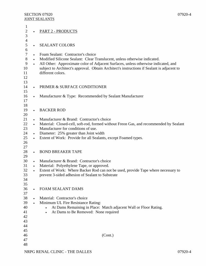
SECTION 07920 07920-4 JOINT SEALANTS
NRPG RENAL CLINIC - THE DALLES 07920-4
1 • PART 2 - PRODUCTS 2 3 4 • SEALANT COLORS 5 6 • Foam Sealant: Contractor's choice 7 • Modified Silicone Sealant: Clear Translucent, unless otherwise indicated. 8 • All Other: Approximate color of Adjacent Surfaces, unless otherwise indicated, and 9
subject to Architect's approval. Obtain Architect's instructions if Sealant is adjacent to 10 different colors. 11
12 13 • PRIMER & SURFACE CONDITIONER 14 15 • Manufacturer & Type: Recommended by Sealant Manufacturer 16 17 18 • BACKER ROD 19 20 • Manufacturer & Brand: Contractor's choice 21 • Material: Closed-cell, soft-rod, formed without Freon Gas, and recommended by Sealant 22
Manufacturer for conditions of use. 23 • Diameter: 25% greater than Joint width 24 • Extent of Work: Provide for all Sealants, except Foamed types. 25 26 27 • BOND BREAKER TAPE 28 29 • Manufacturer & Brand: Contractor's choice 30 • Material: Polyethylene Tape, or approved. 31 • Extent of Work: Where Backer Rod can not be used, provide Tape where necessary to 32
prevent 3-sided adhesion of Sealant to Substrate 33 34 35 • FOAM SEALANT DAMS 36 37 • Material: Contractor's choice 38 • Minimum UL Fire Resistance Rating: 39
• At Dams Remaining in Place: Match adjacent Wall or Floor Rating. 40 • At Dams to Be Removed: None required 41
42 43 44 45
(Cont.) 46 47 48
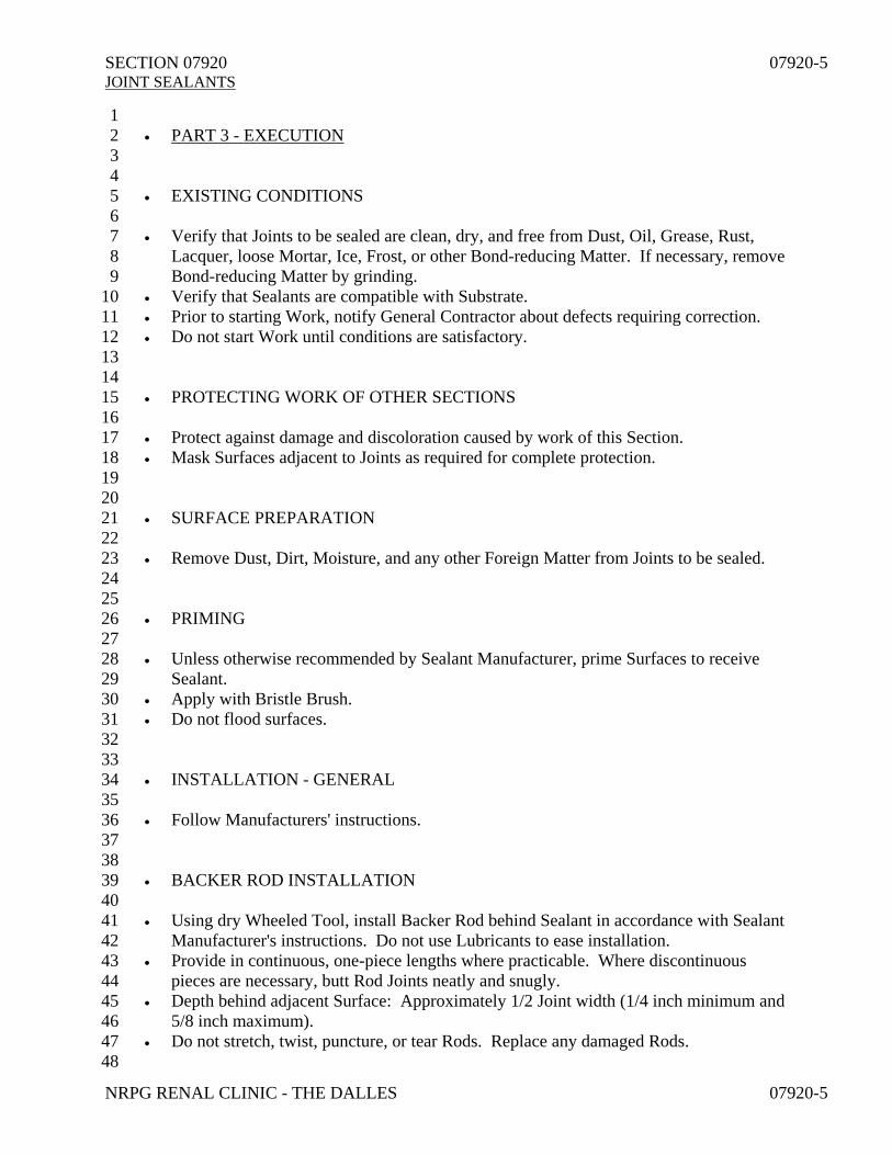
SECTION 07920 07920-5 JOINT SEALANTS
NRPG RENAL CLINIC - THE DALLES 07920-5
1 • PART 3 - EXECUTION 2 3 4 • EXISTING CONDITIONS 5 6 • Verify that Joints to be sealed are clean, dry, and free from Dust, Oil, Grease, Rust, 7
Lacquer, loose Mortar, Ice, Frost, or other Bond-reducing Matter. If necessary, remove 8 Bond-reducing Matter by grinding. 9
• Verify that Sealants are compatible with Substrate. 10 • Prior to starting Work, notify General Contractor about defects requiring correction. 11 • Do not start Work until conditions are satisfactory. 12 13 14 • PROTECTING WORK OF OTHER SECTIONS 15 16 • Protect against damage and discoloration caused by work of this Section. 17 • Mask Surfaces adjacent to Joints as required for complete protection. 18 19 20 • SURFACE PREPARATION 21 22 • Remove Dust, Dirt, Moisture, and any other Foreign Matter from Joints to be sealed. 23 24 25 • PRIMING 26 27 • Unless otherwise recommended by Sealant Manufacturer, prime Surfaces to receive 28
Sealant. 29 • Apply with Bristle Brush. 30 • Do not flood surfaces. 31 32 33 • INSTALLATION - GENERAL 34 35 • Follow Manufacturers' instructions. 36 37 38 • BACKER ROD INSTALLATION 39 40 • Using dry Wheeled Tool, install Backer Rod behind Sealant in accordance with Sealant 41
Manufacturer's instructions. Do not use Lubricants to ease installation. 42 • Provide in continuous, one-piece lengths where practicable. Where discontinuous 43
pieces are necessary, butt Rod Joints neatly and snugly. 44 • Depth behind adjacent Surface: Approximately 1/2 Joint width (1/4 inch minimum and 45
5/8 inch maximum). 46 • Do not stretch, twist, puncture, or tear Rods. Replace any damaged Rods. 47 48

SECTION 07920 07920-6 JOINT SEALANTS
NRPG RENAL CLINIC - THE DALLES 07920-6
1 • PART 3 - EXECUTION 2 3 4 • DAM INSTALLATION 5 6 • Provide around Wall and Floor Penetrations to receive Foam Penetration Sealant. 7 8 9 • FOAM SEALANT INSTALLATION 10 11 • Inject Sealant continuously until Opening is filled. 12 • If Opening is not filled within Sealant Snap Time or maximum of 3 minutes, stop 13
application for at least 15 minutes before resuming work. 14 • Trim cured Foam flush with Adjacent Surface. 15 • Remove any combustible Dams. 16 17 18 • MODIFIED SILICONE (STPe) & ACRYLIC LATEX SEALANT INSTALLATION 19 20 • Apply in accordance with Manufacturer's instructions using Hand or Pressure Gun-type 21
Dispenser. 22 • Size Gun Nozzle to fit Joint. 23 • Force Sealant into Joints firmly against Joint Sides to fill Joints and Voids solid; superficial 24
pointing with Skin Bead not acceptable. 25 • Prevent 3-sided adhesion of Sealant to Substrate. 26 • Install Sealant flush with Adjacent Surface. 27 • Within 10 minutes after installation, and using Dry Tool finish Sealant to smooth, 28
uniform, and slightly concave shape. 29 • Remove excess Sealant and Masking Materials, if any, immediately after Sealant 30
installation. 31 • Leave Sealant Surfaces neat and smooth. 32 33 34 • WASTE MANAGEMENT 35 36 • Place used Sealant Tubes, Dispensers, and Pails in Hazardous Materials containers. 37 38 39 • PRODUCT CLEANING & REPAIRING 40 41 • Including Work of other Trades, clean, repair and touch-up, or replace when directed, 42
Products which have been soiled, discolored, or damaged by Work of this Section. 43 • Remove Debris from Project Site upon Work completion, or sooner if directed. 44 45 46
END OF SECTION 47 48

SECTION 08110 08110-1 HOLLOW STEEL DOORS & FRAMES
NRPG RENAL CLINIC - THE DALLES 08110-1
1 • PART 1 - GENERAL 2 3 4 • CONTRACT CONDITIONS 5 6 • Work of this Section is bound by the Contract Conditions and Division 1, bound 7
herewith, in addition to this Specification and accompanying Drawings. 8 9 10 • RELATED WORK SPECIFIED IN OTHER SECTIONS 11
12 • Grouting Frames in Masonry Walls: Section 04200 13 • Caulking Exterior Door Frames: Section 07920 14 • Aluminum Doors & Frames: Section 08400 15 • Door Hardware: Section 08710 16 • Field Painting: Section 09900 17 18 19 • ALTERNATES 20 21 • Refer to Section 01200 for possible effect upon Work of this Section. 22 23 24 • REFERENCED SPECIFICATIONS 25 26 • Except as modified herein, conform to the following Recommended Specifications 27
published by Steel Door Inst.; 30200 Detroit Rd.; Cleveland, OH 44145-1967; (216) 28 892-1404. 29
• S.D.I. 100 Standard Steel Doors and Frames 30 • S.D.I. 105 Steel Frame Erection Instructions 31 • S.D.I. 107 Hardware on Steel Doors 32 • S.D.I. 117 Manufacturing Tolerances 33 • S.D.I. 118 Basic Fire Door Requirements 34 • A.N.S.I. A151.1 Acceptance Criteria for Steel Doors & Hardware Reinforcings. 35 • A.N.S.I. A224.1 Acceptance Criteria for Painted Surfaces 36
• Specifications can be obtained from Institute. 37 38 39 • COORDINATION 40 41 • Coordinate with other Trades affecting or affected by Work of this Section. 42 43 44 45 46 47 48

SECTION 08110 08110-2 HOLLOW STEEL DOORS & FRAMES
NRPG RENAL CLINIC - THE DALLES 08110-2
1 • PART 1 - GENERAL 2 3 4 • SHOP DRAWINGS 5 6 • Submit in accordance with Section 01330. 7 • Show locations, elevations, principal construction features, and dimensions of each Door 8
type and Frame type, cut-outs, reinforcement, joints, welds, finish, anchoring, and other 9 pertinent details. 10
• Locate and detail Field Splice Joints for any Frames too large to ship in one piece. Indicate 11 instructions for making Field Splices. 12
• Manufacturer's published details may be substituted for Standard Stock Items, provided 13 required information is included. 14
15 16 • REGULATORY AGENCY REQUIREMENTS 17 18 • Fabricate Doors and Frames, where scheduled to be Fire-resistive, in accordance with 19
requirements of Underwriters Laboratories, Factory Mutual, or other Agency approved 20 by Building Official. Affix Agency Acceptance Label on each piece. 21
• If and where Doors are required to be "Positive Pressure" type, accompany Code-22 compliance Installation Instructions with Door shipment. 23
24 25 • CERTIFICATE OF COMPLIANCE 26 27 • Furnish Certificate from Manufacturer stating that Hollow Steelwork delivered to Project 28
conforms to these Specifications. In lieu of submitting Certificate, Manufacturer may affix 29 Certifying Label on each Unit, as defined in Referenced Specifications. 30
31 32 • PRODUCT DELIVERY, STORAGE, & HANDLING 33 34 • Protect against damage and discoloration. 35 • Remove Door Wrappings upon Jobsite delivery. 36 • Store Doors and Frames upright in protected dry area, at least 1 inch above Ground or 37
Floor, and with at least 1/4 inch between individual pieces. 38 • Brace bottom ends of Frame Jambs against displacement. 39 40 41 • FIELD MEASUREMENTS 42 43 • Verify prior to fabrication. 44 • If field measurements differ slightly from Drawing dimensions modify Work as required 45
for accurate fit. If measurements differ substantially, notify Architect prior to fabrication. 46 47 48
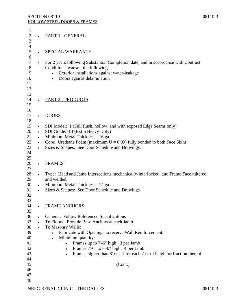
SECTION 08110 08110-3 HOLLOW STEEL DOORS & FRAMES
NRPG RENAL CLINIC - THE DALLES 08110-3
1 • PART 1 - GENERAL 2 3 4 • SPECIAL WARRANTY 5 6 • For 2 years following Substantial Completion date, and in accordance with Contract 7
Conditions, warrant the following: 8 • Exterior installations against water-leakage 9 • Doors against delamination 10
11 12 13 • PART 2 - PRODUCTS 14 15 16 • DOORS 17 18 • SDI Model: 1 (Full flush, hollow, and with exposed Edge Seams only) 19 • SDI Grade: III (Extra Heavy Duty) 20 • Minimum Metal Thickness: 16 ga. 21 • Core: Urethane Foam (maximum U = 0.09) fully bonded to both Face Skins 22 • Sizes & Shapes: See Door Schedule and Drawings. 23 24 25 • FRAMES 26 27 • Type: Head and Jamb Intersections mechanically-interlocked, and Frame Face mitered 28
and welded. 29 • Minimum Metal Thickness: 14 ga. 30 • Sizes & Shapes: See Door Schedule and Drawings. 31 32 33 • FRAME ANCHORS 34 35 • General: Follow Referenced Specifications 36 • To Floors: Provide Base Anchors at each Jamb. 37 • To Masonry Walls: 38
• Fabricate with Openings to receive Wall Reinforcement. 39 • Minimum quantity: 40
• Frames up to 7'-6" high: 3 per Jamb 41 • Frames 7'-6" to 8'-0" high: 4 per Jamb 42 • Frames higher than 8'-0": 1 for each 2 ft. of height or fraction thereof 43 44
(Cont.) 45 46 47 48

SECTION 08110 08110-4 HOLLOW STEEL DOORS & FRAMES
NRPG RENAL CLINIC - THE DALLES 08110-4
1 • PART 2 - PRODUCTS 2 3 4 • FRAME ANCHORS (Cont.) 5
6 • To Stud Walls: 7
• Full Frame width and depth, and welded to Frame. 8 • Minimum quantity: 9
• Frames up to 7'-6" high: 4 per Jamb 10 • Frames 7'-6" to 8'-0" high: 5 per Jamb 11 • Frames higher than 8'-0": 5 Anchors plus 1 additional for each 2 ft. or 12
fraction thereof over 8'-0" 13 14 15 • FABRICATION 16 17 • Follow Referenced Specification. 18 • Accurately form Metal to required sizes and shapes. 19 • Bevel Lock-side Edge of Doors 1/8 inch in 2 inches. Square edged Doors not acceptable. 20 • Minimum Reinforcement Thickness: 21
• At Hinges: 8 ga. 22 • At Locks: 16 ga. 23 • At Surface Hardware: 12 ga. 24
• Assemble Components and grind and dress Welds to form smooth, flush surfaces, 25 which do not show Weld or Fabrication Marks after painting when viewed from 26 oblique angle. Do not use Metallic Fillers to conceal Defects. 27
• Fabricate with 26 ga. minimum Cover Boxes at Hardware Mortises. 28 • Provide High Frequency Reinforcement at top and bottom of Top Hinges. 29 • Weld Anchors to Door Frames. 30 • Fabricate with the following clearances: 31
• Between Doors and Frames: 1/8 inch 32 • Between Door Bottoms and Thresholds: 1/4 inch 33 • Between Door Bottoms and Floor: 3/4 inch 34 • Between Meeting Edges of pairs of Doors: 3/32 inch 35
• Prepare Frames to receive Silencers specified in Section 08710. 36 • Fabricate any exterior, out-swinging Doors with flush tops. 37 • Fabricate any closed-section Mullions with internal Web Reinforcement. 38 39 40 • SHOP FINISH 41 42 • Dress Surface irregularities to smooth surface. 43 • Chemically treat and clean exposed Surfaces. 44 • Treatment: 45
• All Surfaces of Exterior Doors & Frames: Electro-galvanized Coating (Note: 46 Wipe-coated Galvanized Steel will not be accepted.) 47
48

SECTION 08110 08110-5 HOLLOW STEEL DOORS & FRAMES
NRPG RENAL CLINIC - THE DALLES 08110-5
1 • PART 3 - EXECUTION 2 3 4 • EXISTING CONDITIONS 5 6 • Verify that Openings to receive Hollow Steelwork are accurately sized and located, 7
square, plumb, and otherwise properly prepared. 8 • Prior to starting Work, notify General Contractor about defects requiring correction. 9 • Do not start Work until conditions are satisfactory. 10 11 12 • PROTECTING WORK OF OTHER SECTIONS 13 14 • Protect against damage and discoloration caused by Work of this Section. 15 16 17 • INSTALLATION 18 19 • Follow Referenced Specifications and Manufacturer's instructions. 20 • Secure Anchors to Adjacent Construction. 21 • Set Frames true with Adjacent Construction. 22 • Accurately position Work. 23 • Set Doors flush with Frame face. 24 • Set Doors plumb to hold any desired position. 25 • Fill any exposed Fastener Heads, and finish to match adjacent Surface. 26 27 28 • ADJUSTMENTS 29 30 • Adjust Moving Parts to operate satisfactorily at time of Project Substantial Completion 31
and during Warranty Period. 32 33 34 • PRODUCT CLEANING & REPAIRING 35 36 • Collect Cut-offs and Scrap, and place where directed for recycling. 37 • Including Work of other Trades, clean, repair and touch-up, or replace when directed, 38
Products which have been soiled, discolored, or damaged by Work of this Section. 39 • Leave surfaces ready for Finish Painting specified in Section 09900. 40 • Remove Debris from Project Site upon Work completion, or sooner if directed. 41 42 43 44 45
END OF SECTION 46 47 48

SECTION 08400 08400-1 ALUMINUM ENTRANCE & WINDOW WALL SYSTEMS
NRPG RENAL CLINIC - THE DALLES 08400-1
1 • PART 1 - GENERAL 2 3 • CONTRACT CONDITIONS 4 5 • Work of this Section is bound by the Contract Conditions and Division 1, bound 6
herewith, in addition to this Specification and accompanying Drawings. 7 8 9 • PRODUCTS INSTALLED, BUT FURNISHED UNDER OTHER SECTIONS 10 11 • Door Hardware specified in Section 08710. 12 • Glazing specified in Section 08800 13 14 15 • RELATED WORK SPECIFIED IN OTHER SECTIONS 16 17 • Joint Caulking & Sealing: Section 07920 18 • Hollow Steel Doors & Frames: Section 08110 19 • Automatic Sliding Door Operators: Section 08460 20 21 22 • ALTERNATES 23 24 • Refer to Section 01200 for possible effect upon Work of this Section. 25 26 27 • REFERENCED SPECIFICATIONS 28 29 • Comply with applicable portions of manufacturing and installation recommendations of 30
American Architectural Manufacturer's Association, hereinafter referred to as AAMA; 31 1827 Walden Office Square; Suite 550; Schaumburg, IL 60173; (847) 303-5664. 32
• Copies can be obtained from Association. 33 34 35 • SYSTEM DESIGN REQUIREMENTS 36 37 • In accordance with governing laws, regulations, codes, and requirements specified in 38
Section 01115; design, engineer, fabricate, and install Work of this Section including 39 System Supports & Attachments, in compliance with Drawings, Specifications, and the 40 following Design Loads: 41
• Loads listed in Structural Notes on Drawings 42 • Loads induced by Window Washing 43 • Wind Loads: Satisfy Building Code Exposure D requirements 44 • Maximum Surface Deflection: 45
• Spans up to 14 ft.: L/240 46 • Spans 14 ft. & Greater: L/300 47 • Do not cause loss of Glass Bite greater than 25% of Design Dimension 48

SECTION 08400 08400-2 ALUMINUM ENTRANCE & WINDOW WALL SYSTEMS
NRPG RENAL CLINIC - THE DALLES 08400-2
1 • PART 1 - GENERAL 2 3 4 • SYSTEM PERFORMANCE REQUIREMENTS 5 6 • Design, engineer, fabricate, and install Work of this Section to satisfy the following: 7
• Withstand Thermal Expansion induced by up to 60º F Temperature Shift 8 without System buckling, Glass stress, Sealant failure, Fastener damage, or 9 other detrimental effects. 10
• Minimum AAMA 1502.7 Condensation Resistance Factor (CRF): 60 11 • ASTM E-1105 & AAMA 503 System Water Penetration Field Test conducted 12
at 6.24 psi min. prior to installation of Interior Finish Materials: No penetration 13 14 15 • CERTIFICATE OF COMPLIANCE 16 17 • Submit certification, signed and sealed by Engineer registered to practice in Oregon, 18
which stipulates that Work of this Section complies with Design & Performance 19 Requirements specified above. 20
• If Work, as specified herein and shown on Drawings, is not capable of complying with 21 Design & Performance Requirements specified above, so notify Architect at least 5 22 working days prior to Contract award. 23
24 25 • COORDINATION 26 27 • Coordinate with other Trades affecting or affected by Work of this Section. 28 29 30 • INSTALLER'S QUALIFICATIONS 31 32 • Employed by or acceptable to Manufacturer. 33 34 35 • SHOP DRAWINGS 36 37 • Submit in accordance with Section 01330. 38 • Show construction, materials, profiles, thicknesses, dimensions, fasteners, supports, 39
anchors, required clearances, and other pertinent details. 40 41 42 • SAMPLES 43 44 • Submit in accordance with Section 01330. 45 • Include two 12 inch long Samples of specified Metal Finishes. 46 • Match fabricated Work with accepted Samples. 47 48

SECTION 08400 08400-3 ALUMINUM ENTRANCE & WINDOW WALL SYSTEMS
NRPG RENAL CLINIC - THE DALLES 08400-3
1 • PART 1 - GENERAL 2 3 4 • PRODUCT DELIVERY 5 6 • Coordinate with General Contractor's work schedule. 7 8 9 • PRODUCT STORAGE & HANDLING 10 11 • Protect against damage and discoloration. 12 13 14 • FIELD MEASUREMENTS 15 16 • Verify prior to fabrication. 17 • If field measurements differ slightly from Drawing dimensions modify Work as required 18
for accurate fit. If measurements differ substantially, notify Architect prior to fabrication. 19 20 21 • SPECIAL WARRANTY 22 23 • For 2 years following Substantial Completion date, and in accordance with Contract 24
Conditions, warrant exterior installations against water-leakage and air-infiltration. 25 26 27 28 • PART 2 - PRODUCTS 29 30 31 • ALUMINUM 32 33 • Alloys & Tempers, unless otherwise modified, as follows: 34
• Exposed Extrusions: 6063-T6 35 • Structural Shapes, Blocking, Bracing, & other Concealed Members: 06063-T6 36 • Casting: 214-T6 37 • Sheetmetal: 5005-H32 38 • Special Finishes: Modify Alloys and Tempers specified above as necessary for 39
proper application of any Special Finishes specified hereunder. 40 • Finish: 41
• Concealed Work: Mill finish 42 • Exposed Work: AAMA 611 Class 1 Anodic 43 • Color: Clear 44 • Minimum Coating Thickness: 0.7 mils 45
46 47 48

SECTION 08400 08400-4 ALUMINUM ENTRANCE & WINDOW WALL SYSTEMS
NRPG RENAL CLINIC - THE DALLES 08400-4
1 • PART 2 - PRODUCTS 2 3 4 • STEEL REINFORCING 5 6 • Manufacturing Standard: ASTM A-36 7 8 9 • FASTENERS 10 11 • Type: Recommended by Manufacturer for conditions of use 12 • Material: Galvanically compatible with Adjacent Materials 13 • Finish: 14
• Where Exposed to View: Match Adjacent Material 15 • Where Concealed: Contractor's choice 16
17 18 • CORROSION INSULATING COMPOUND 19 20 • Material: Asphaltic Coating Compound 21 • Manufacturing Standard: Fed. Spec. TT-C-494 type II 22 23 24 • DOOR FRAMES & WINDOW WALL FRAMES 25 26 • Material: Aluminum 27 • Manufacturer: Arcadia, Kawneer, US Aluminum, Vistawall, or approved. 28 • Series: Match Kawneer VG 451T 29 30 31 • DOORS 32 33 • Material: Aluminum 34 • Manufacturer: Arcadia, Kawneer, US Aluminum, Vistawall, or approved. 35 • Stile Width: 3-1/2 inches 36 37 38 • GLAZING STOPS 39 40 • Material: Match Frame Stock. 41 • Shape: Square 42 43 44 • DOOR HARDWARE 45 46 • See Section 08710 47 48

SECTION 08400 08400-5 ALUMINUM ENTRANCE & WINDOW WALL SYSTEMS
NRPG RENAL CLINIC - THE DALLES 08400-5
1 • PART 2 - PRODUCTS 2 3 4 • DOOR WEATHERSTRIPPING 5 6 • Material: Flexible nonporous Polymeric Strip 7 • Features: 8
• All Weatherstripping: Easily replaceable 9 • Sill Weatherstripping: Easily adjustable for wear 10
11 12 • ACCESSORIES 13 14 • Provide Attachment Embeds, Flashings, Break-metal Closures, Connectors, Trim, etc. 15
necessary for complete, weatherproof, and secure installation. 16 17 18 • FABRICATION 19 20 • Comply with applicable portions of Referenced Specifications. 21 • Provide concealed Steel Reinforcement where indicated or required to resist Wind or 22
other Applied Loads. 23 • Fabricate Connections as required for strength and rigidity using concealed Mechanical 24
Fastenings wherever possible. Where not possible, welding may be used. 25 • Drain Glazing Channels to prevent Insulating Glass from standing in Water. 26 • Fabricate with Weep Holes to evacuate to Building Exterior any exterior Water or 27
interior Condensation. 28 • Cut Horizontal Members between Vertical Members. 29 • Match exposed Welds with adjacent Material, free of porosity, cracks, and blow-holes. 30 • Select Materials carefully for matching Color and Texture after finishing. 31 • Fabricate Flat Surface smooth and true, and free from waves, buckles, and seams. 32 • Fabricate Edges, Corners, and Angles clean, sharp, and square. 33 • Fit Members with hairline, virtually invisible joints. 34 • Allow for expansion and contraction. 35 • Prevent Noise resulting from thermally-induced Material movement, Vibration 36
harmonics, or Wind passage. 37 • Make Exterior Work permanently weathertight. 38 • Fabricate with the following clearances: 39
• Between Doors & Frames: 1/8 inch 40 • Between Door Bottoms & Thresholds: 1/4 inch 41 • Between Door Bottoms & Floor: 3/4 inch 42 • Between Meeting Edges of pairs of Doors: 1/8 inch 43
44 45 46 47 48
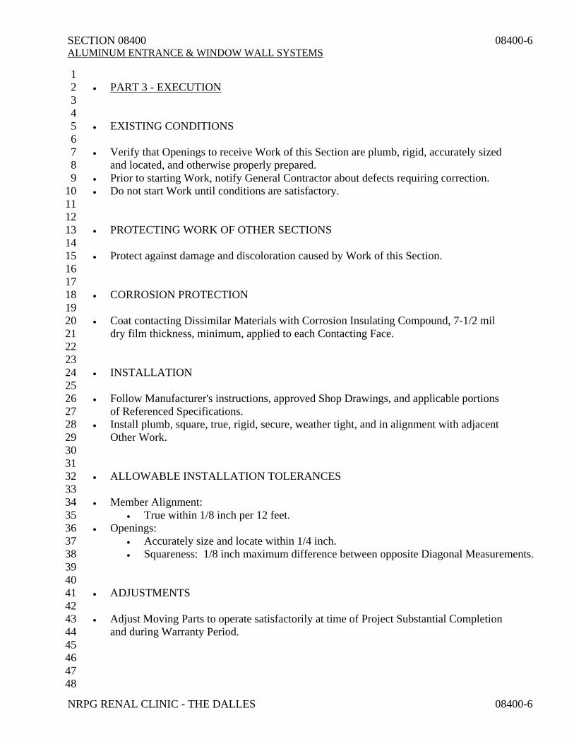
SECTION 08400 08400-6 ALUMINUM ENTRANCE & WINDOW WALL SYSTEMS
NRPG RENAL CLINIC - THE DALLES 08400-6
1 • PART 3 - EXECUTION 2 3 4 • EXISTING CONDITIONS 5 6 • Verify that Openings to receive Work of this Section are plumb, rigid, accurately sized 7
and located, and otherwise properly prepared. 8 • Prior to starting Work, notify General Contractor about defects requiring correction. 9 • Do not start Work until conditions are satisfactory. 10 11 12 • PROTECTING WORK OF OTHER SECTIONS 13 14 • Protect against damage and discoloration caused by Work of this Section. 15 16 17 • CORROSION PROTECTION 18 19 • Coat contacting Dissimilar Materials with Corrosion Insulating Compound, 7-1/2 mil 20
dry film thickness, minimum, applied to each Contacting Face. 21 22 23 • INSTALLATION 24 25 • Follow Manufacturer's instructions, approved Shop Drawings, and applicable portions 26
of Referenced Specifications. 27 • Install plumb, square, true, rigid, secure, weather tight, and in alignment with adjacent 28
Other Work. 29 30 31 • ALLOWABLE INSTALLATION TOLERANCES 32 33 • Member Alignment: 34
• True within 1/8 inch per 12 feet. 35 • Openings: 36
• Accurately size and locate within 1/4 inch. 37 • Squareness: 1/8 inch maximum difference between opposite Diagonal Measurements. 38
39 40 • ADJUSTMENTS 41 42 • Adjust Moving Parts to operate satisfactorily at time of Project Substantial Completion 43
and during Warranty Period. 44 45 46 47 48

SECTION 08400 08400-7 ALUMINUM ENTRANCE & WINDOW WALL SYSTEMS
NRPG RENAL CLINIC - THE DALLES 08400-7
1 • PART 3 - EXECUTION 2 3 4 • TOUCH-UP PAINTING 5 6 • Touch-up any exposed Metal Finish damaged by cutting. Match adjacent Finish. 7 8 9 • PRODUCT CLEANING & REPAIRING 10 11 • Remove Protective Coatings. 12 • Including Work of other Trades, clean, repair and touch-up, or replace when directed, 13
Products which have been soiled, discolored, or damaged by work of this Section. 14 • Final Glass cleaning specified in Section 01740. 15 • Collect Cut-offs and Scrap, and place where directed for recycling. 16 • Remove Debris from Project Site upon work completion or sooner, if directed. 17 18 19 20 21 22
END OF SECTION 23 24 25 26 27 28 29 30 31 32 33 34 35 36 37 38 39 40 41 42 43 44 45 46 47 48

SECTION 08460 08460-1 AUTOMATIC OPERATING DOORS
NRPG RENAL CLINIC - THE DALLES 08460-1
1 • PART 1 - GENERAL 2 3 • CONTRACT CONDITIONS 4 5 • Work of this Section is bound by the Contract Conditions and Division 1, bound 6
herewith, in addition to this Specification and accompanying Drawings. 7 8 9 • EXTENT OF WORK 10 11 • Provide automatic operating Entrance System including adjacent Door Frames, 12
Transom Frames, and Doors. 13 14 15 • RELATED WORK SPECIFIED IN OTHER SECTIONS 16 17 • Hollow Steel Entrance Systems: Section 08110 18 • Aluminum Entrance Systems: Section 08400 19 • Door Hardware: Section 08710 20 • Glazing: Section 08800 21 • Electric Conduit, Wiring, & connections to Automatic Operators: Div. 16 22 23 24 • ALTERNATES 25 26 • Refer to Section 01200 for possible effect upon Work of this Section. 27 28 29 • COORDINATION 30 31 • Coordinate with other Trades affecting or affected by Work of this Section. 32 33 34 • SHOP DRAWINGS 35 36 • Submit in accordance with Section 01330. 37 • Show Motion Detector appearance, locations, and utility connections. 38 • Show Door Operator type, location, and utility connections. 39 • Show Frame material, finish, profiles, dimensions, anchors, required clearances, utility 40
connections, and other pertinent details. 41 42 43 • SAMPLES 44 45 • In accordance with Section 01330, submit two 12 inch long Samples of specified Metal 46
Finishes. 47 • Match fabricated Work with accepted Samples. 48

SECTION 08460 08460-2 AUTOMATIC OPERATING DOORS
NRPG RENAL CLINIC - THE DALLES 08460-2
1 • PART 1 - GENERAL 2 3 4 • OPERATION & MAINTENANCE INSTRUCTIONS 5 6 • In accordance with Section 01830, submit Instructions to General Contractor for inclusion 7
in Owner's Maintenance Manual. 8 9 10 • INSTALLER'S QUALIFICATIONS 11 12 • Employed by or acceptable to Equipment Manufacturer. 13 14 15 • REGULATORY AGENCY REQUIREMENTS 16 17 • Micro-wave Motion Detectors shall conform to Federal Communications Commission 18
Regulations. 19 • Comply with applicable requirements of US Americans with Disabilities Act. 20 21 22 • PRODUCT DELIVERY, STORAGE, & HANDLING 23 24 • Protect against damage and discoloration. 25 26 27 • FIELD MEASUREMENTS 28 29 • Verify prior to fabrication. 30 • If field measurements differ slightly from Drawing dimensions, modify Work as required 31
for accurate fit. If measurements differ substantially, notify Architect prior to fabrication. 32 33 34 • WARRANTY 35 36 • For 2 years following Project Substantial Completion date warrant the following: 37
• Operating and Safety Devices against faulty operation. 38 • Exterior Work to be weatherproof. 39
40 41 42 • PART 2 - PRODUCTS 43 44 45 • DOORS & FRAMES 46 47 • Match Work specified in Section 08400. 48

SECTION 08460 08460-3 AUTOMATIC OPERATING DOORS
NRPG RENAL CLINIC - THE DALLES 08460-3
1 • PART 2 - PRODUCTS 2 3 4 • DOOR OPERATING SYSTEM 5 6 • Manufacturer: Besam, or approved. 7 • Model: Power Glide 4000 8 • Type: Concealed Header 9 • Door Operation: Bi-parting Slideaway 10 • BHMA Manufacturing Standard: A156.10 11 • Activator Housing: 12
• Type: Vandal-proof 13 • Material: Non-corrosive 14 • Finish: Match adjacent Frames. 15
• Required Features: 16 • Units shall be self-contained and complete with all Accessories required for 17
easy operation. 18 • With no more than 50 ft. lb. pressure, Operators shall permit manual Door 19
operation with power on or off. When opened manually, Doors shall 20 automatically close. 21
• Doors shall automatically reverse should Obstruction interfere with Door 22 Closing Cycle. 23
• Breakaway Emergency Egress with no more than 50 lbs. pressure applied at the 24 Lock Stile. 25
• Operators shall perform properly when exposed to exterior weather environments 26 including -20ºF to +140ºF temperature range. 27
28 29 • DOOR & FRAME FABRICATION 30 31 • Provide concealed Steel Reinforcement where indicated or required to resist Wind or 32
other Applied Loads. 33 • Fabricate Connections as required for strength and rigidity using concealed Mechanical 34
Fastenings wherever possible. Where not possible, welding may be used. 35 • Cut Horizontal Members between Vertical Members. 36 • Match exposed Welds with adjacent Material, free of porosity, cracks, blow-holes, and 37
splatters. 38 • Select Materials carefully for matching Color and Texture after finishing. 39 • Fabricate Flat Surface smooth and true, and free from waves, buckles, and seams. 40 • Fabricate Edges, Corners, and Angles clean, sharp, and square. 41 • Fit Members with hairline, virtually invisible joints. 42 • Allow for expansion and contraction. 43 • Prevent Noise resulting from thermally-induced Material movement, Vibration 44
harmonics, or Wind passage. 45 • Make Exterior Work permanently weather tight. 46 • Weep any Condensation or Migrating Moisture to exterior. 47 48

SECTION 08460 08460-4 AUTOMATIC OPERATING DOORS
NRPG RENAL CLINIC - THE DALLES 08460-4
1 • PART 2 - PRODUCTS 2 3 4 • SIGNAGE 5 6 • On both faces of each Door, provide High-Visibility Decal indicating “CAUTION - 7
SLIDING DOOR”. Mount Decals at 58 inches above Floor. 8 • On egress-face of Emergency Breakaway Panels, provide High-Visibility Decal 9
indicating “EMERGENCY EXIT PANEL”. Mount Decal adjacent to Lock Stile at 10 58 inches above Floor. 11
12 13 14 • PART 3 - EXECUTION 15 16 17 • EXISTING CONDITIONS 18 19 • Verify that Openings to receive Operators and that Utility Rough-ins are properly prepared. 20 • Prior to starting Work, notify General Contractor about defects requiring correction. 21 • Do not start Work until conditions are satisfactory. 22 23 24 • PROTECTING WORK OF OTHER SECTIONS 25 26 • Protect against damage and discoloration caused by Work of this Section. 27 28 29 • INSTALLATION 30 31 • Follow Manufacturer's instructions and approved Shop Drawings. 32 • Secure Work plumb, level, square, straight, and true as applicable. 33 • Make Utility connections. 34 35 36 • ADJUSTMENTS 37 38 • Adjust Moving Parts to operate satisfactorily at time of Project Substantial Completion 39
and during Warranty Period. 40 41 42 • PRODUCT CLEANING & REPAIRING 43 44 • Including Work of other Trades, clean, repair and touch-up, or replace when directed, 45
Products which have been soiled, discolored, or damaged by Work of this Section. 46 • Remove Debris from Project Site upon Work completion, or sooner if directed. 47
END OF SECTION 48

SECTION 08710 08710-1 DOOR HARDWARE
NRPG RENAL CLINIC - THE DALLES 08710-1
1 • PART 1 - GENERAL 2 3 4 • CONTRACT CONDITIONS 5 6 • Work of this Section is bound by the Contract Conditions and Division 1, bound 7
herewith, in addition to this Specification and accompanying Drawings. 8 9 10 • RELATED WORK SPECIFIED IN OTHER SECTIONS 11 12 • Hardware for the following Items: 13
• Roof Hatch: Section 07720 14 • Mechanical & Electrical Equipment: Division 15 & 16 respectively 15
• Hardware for the following Items, except Locks: 16 • Automatic Operating Entrances: Section 08460 17
18 19 • PRODUCT SUBSTITUTIONS 20 21 • Comply with requirements specified in Section 01630. 22 • Include with Request: Specified Item, Design, Catalog Number, and Finish for each 23
Item on which approval is being requested. Blanket approval by Manufacturer's Name 24 only will not be given. 25
26 27 • ALTERNATES 28 29 • Refer to Section 01200 for possible effect upon Work of this Section. 30 31 32 • COORDINATION 33 34 • Coordinate with other Trades affecting or affected by Work of this Section. 35 • No later that 10 working days following Hardware Schedule acceptance, furnish 36
Hardware Templates to Door and Frame Manufacturers. 37 38 39 • SUPPLIER'S HARDWARE SCHEDULE 40 41 • Submit similar to Shop Drawings in accordance with Section 01330. 42 • Organize into Hardware Sets, and indicate each Item, Opening, Door size, Door hand, 43
Frame Material, Fire-resistance Label Rating, Keying, Material, Finish, and 44 Manufacturer's Model Number. 45
46 47 48

SECTION 08710 08710-2 DOOR HARDWARE
NRPG RENAL CLINIC - THE DALLES 08710-2
1 • PART 1 - GENERAL 2 3 4 • SUPPLIER'S REPRESENTATIVE 5 6 • Hardware Supplier shall employ AHC-certified Consultant, who shall be available for 7
consultation with Architect and Contractor during course of Work. 8 • Supplier's Representative shall meet with Owner's Representative to prepare final 9
Keying Schedule. 10 • Prior to Final Project Acceptance, Supplier's Representative shall: 11
• Make 1 field inspection and notify Architect if Hardware installation complies 12 with Manufacturers' instructions and these Specifications. 13
• Instruct Owner how to properly adjust and maintain Hardware. 14 15 16 • REGULATORY AGENCY REQUIREMENTS 17 18 • Conform to applicable requirements of Americans with Disabilities Act. 19 20 21 • CERTIFICATION OF COMPLIANCE 22 23 • Prior to Substantial Completion, certify in writing that Hardware provided complies 24
with these Specifications and approved Hardware Schedule. 25 26 27 • PRODUCT DELIVERY 28 29 • Package each Item separately, and identify with Hardware Schedule Number. 30 • Deliver to General Contractor for installation, in original, unopened Containers with 31
legible Labels intact. 32 • Include Manufacturers' Installation Instructions. 33 • Include complete set of specialized Hardware Maintenance and Removal Tools 34
necessary for Owner's use. Store where directed by Owner. 35 • Ship tagged and identified Permanent Keys and Interchangeable Cores, if any, by 36
Registered Mail to: 37 Wayne Armstrong 38 Northwest Renal Property Group 39 3730 SW Shattuck Rd. 40 Portland, OR 97221 41
• Ship Construction Keys directly to Contractor. 42 43 44 • PRODUCT STORAGE & HANDLING 45 46 • Protect against theft, damage, and discoloration. 47 48

SECTION 08710 08710-3 DOOR HARDWARE
NRPG RENAL CLINIC - THE DALLES 08710-3
1 • PART 1 - GENERAL 2 3 4 • FIELD MEASUREMENTS 5 6 • Where necessary, verify Door Openings and Field Measurements prior to fabrication. 7 • Modify Hardware where necessary to fit Door Opening. 8 • If field measurements differ slightly from Drawing dimensions modify Work as required 9
for accurate fit. If measurements differ substantially, notify Architect prior to fabrication. 10 11 12 • SPECIAL WARRANTY 13 14 • Warrant Closers for 10 years against faulty operation. 15 16 17 18 • PART 2 - PRODUCTS 19 20 21 • MANUFACTURERS, MODELS, SIZES, & FINISHES 22 23 • See Schedule at end of Project Manual. 24 • For each type of Hardware: Products shall be produced by single manufacturer, 25
regardless of whether multiple manufacturers are specified. 26 27 28 • LOCKS & LATCHES 29 30 • Lock & Latch Design: Match Falcon Quantum Lever 31 • Lock Cylinders: 32
• Type: Tumbler 33 • Core: 6-pin 34 • Cams and Tailpieces: Provide all required for Door-locking. 35
• Lock Backset, unless otherwise noted elsewhere: 2-3/4 inches 36 • Permanent Core Face Finish: Match adjacent Lock or Latch finish. 37 • Strike Lip: Curved and long enough to protect Door Frame Trim. 38 • Strike Box: Manufacturer's standard type 39 • Minimum Dead Bolt & Latch Bolt extension into Lock Case: 3/8 inch 40 • Lever Handles, if any, shall be solid and not hollow cavity. 41 42 43 • HINGES 44 45 • Type: Mortise 46 47 48

SECTION 08710 08710-4 DOOR HARDWARE
NRPG RENAL CLINIC - THE DALLES 08710-4
1 • PART 2 - PRODUCTS 2 3 4 • DOOR SILENCERS 5 6 • Manufacturer & Model: Ives SR64, or approved. 7 • Required Quantity per Door: 8
• At Doors Frames equipped with Gasketing or Weatherstripping: None 9 • Elsewhere: 10
• At Frames for Single Doors: 3 11 • At Frames for Paired Doors: 4 12
13 14 • DOOR CLOSERS 15 16 • Hydraulic Fluid at Exterior Doors: Consistent Viscosity within plus 120ºF to minus 17
30ºF Temperature Range 18 • At Positive Pressure Doors, if any: Comply with IBC Section 715.3.7. 19 • Mounting Plates: 20
• At any Parallel Arm Closers: Soffit Plate Type 21 • Where Necessary: Drop type 22 • Elsewhere: Surface Shoe type 23
• Equip any Parallel Arm Closers with EDA (heavy duty) Arms. 24 • Fasteners: Concealed 25 • Concealed in Head Type: 26
• Cylinders: High strength Cast Iron 27 • Piston & Arms: Forged Steel 28 • Bearings: High-efficiency & low-friction 29 • Action: Full Rack & Pinion Hydraulic 30
• Hold-open Devices: Adjust to any predetermined angle within limit of Door swing. 31 32 33 • DOOR STOPS 34 35 • In lieu of scheduled Wall Stops or Floor Stops, substitute Concealed Overhead Stays 36
or Closers with Spring Stops, if and where: 37 • Stops create Pedestrian or Vehicle traffic hazard. 38 • 50%, or more, of Door width projects beyond point where Door contacts Door Stop. 39 • Wall Stops or Floor Stops are inappropriate. 40
41 42 • FLUSH BOLTS 43 44 • Size: Follow ANSI and Steel Door Institute recommendations. 45 • Furnish any Floor Bolts with Dust-proof Strikes. 46 • Equip any U.L. approved Bolts with Positive Latching and Automatic Unlocking. 47 48

SECTION 08710 08710-5 DOOR HARDWARE
NRPG RENAL CLINIC - THE DALLES 08710-5
1 • PART 2 - PRODUCTS 2 3 4 • POWER-ASSISTED DOOR OPERATORS 5 6 • Manufacturing Standard: ANSI A156.19 7 • Type: Low-energy requiring neither Guard Rails nor Safety Mats 8 • Emergency Operation: When power is lost, operate as manual Door Closer with 9
adjustable Spring-Power and Hydraulic-Checking 10 • Required Accessories: 11
• Wall, Jamb, or Pedestal-mounted Operating Switches as applicable. 12 • If and where Doors equipped with Power-assisted Closers are paired with 13
adjacent Door equipped with Standard Hydraulic Closer: Standard Closer Cover 14 shall match Cover of Power-assisted Closer. 15
• If and where Doors equipped with Power-assisted Closers are paired with 16 adjacent Door equipped with Concealed Hydraulic Closer: Standard Closer Arm 17 shall match Arm of Power-assisted Closer. 18
19 20 • EXTERIOR EMERGENCY ACCESS KEY STORAGE BOX 21 22 • Manufacturer: Knox Co., (800) 552-5669, or approved. 23 • Brand: Knox-Box 24 • Mounting: Surface 25 • Mounting Height above adjacent Ground Level: 5 ft. 26 • Mounting Location: Adjacent to Building Main Entrance where located on Drawings 27 28 29 • FASTENERS 30 31 • Extent of Work: Provide all required 32 • Material & Finish: Match adjacent Hardware 33 • Types: 34
• If and where applied to Metal: Machine Screws and Bolts 35 • If and where applied to Wood: Full-thread Wood Screws 36 • If and where applied to Plywood or Particle Board: Sheetmetal Screws 37 • If and where applied to Concrete or Masonry: Machine Screws with Expansion 38
Shields 39 • Through-bolting: Not permitted, unless otherwise approved by Architect. 40
• Head Types: 41 • Where Exposed: Phillips 42 • Where Concealed: Contractor's choice 43
44 45 46 47 48
SECTION 08710 08710-6 DOOR HARDWARE
NRPG RENAL CLINIC - THE DALLES 08710-6
1 • PART 2 - PRODUCTS 2 3 4 • KEYS 5 6 • Material: Nickel-Silver, or approved. 7 • Type: Schlage Everest C (master keyed) 8 • Keying Instructions: As directed by Owner 9 • Construction Keying: 10
• Furnish Keys with Factory-keyed Construction Cylinders. 11 • Include 6 Construction Keys for Contractor's use. 12 • Following construction, Hardware Supplier shall convert Locks to Owner's 13
permanent Keying System. 14 • Stamping: 15
• On plain side of Keys, stamp "Do Not Duplicate". 16 • Do not stamp Master Keys with "M" or "Master". 17 • Do not stamp "Bitting Numbers" on Keys. 18
19 20 • FABRICATION 21 22 • Make Hardware for pre-fitted Doors and Frames to Template. Send Templates, together 23
with Hardware Schedule, to Door and Frame Manufacturers no later than 2 weeks after 24 Hardware Schedule approval. 25
• Lock and Latch Components shall be fabricated by only 1 Manufacturer, and carry that 26 Manufacturer's Warranty. 27
• Cut and fit any Threshold or Floor Plates to Door Frame profile and with mitered 28 Corner Joints. Where necessary weld Multiple Pieces together to form single Unit. 29 Fabricate Joints with straight, smooth, and hair-line Seams. 30
31 32 33 • PART 3 - EXECUTION 34 35 36 • EXISTING CONDITIONS 37 38 • Verify that Surfaces to receive Hardware are properly prepared, including necessary 39
Backing. 40 • Prior to starting Work, notify General Contractor about defects requiring correction. 41 • Do not start Work until conditions are satisfactory. 42 43 44 • PROTECTING WORK OF OTHER SECTIONS 45 46 • Protect against damage and discoloration caused by Work of this Section. 47 48


SECTION 08710 08710-7 DOOR HARDWARE
NRPG RENAL CLINIC - THE DALLES 08710-7
1 • PART 3 - EXECUTION 2 3 4 • INSTALLATION 5 6 • Accurately locate, fit, and install square, plumb, and secure in accordance with Manufacturer's 7
instructions and Templates. 8 • Mount Hardware at height shown on the following Mounting Heights Drawing. 9 • Locate any Roller Bumpers at Door top. 10 • Locate any Door Stops at Contact Point. 11 • Install any Kick Plates on push side of Door. 12 • Install Thresholds at Exterior Doors and at any Acoustic Doors in full-bed of Exterior 13
Sealant as specified in Section 07920. Do not plug any Weep Holes. Remove any 14 excess Sealant. 15
• Door Closer Mounting Locations: 16 • At Exterior Doors: On interior-side of Door 17 • At Vestibule Doors, if any: On Vestibule-side of Door 18 • At Corridors: On Room-side of Door 19 • Unless specifically specified elsewhere, do not restrict Door swing. 20
• After fitting any Mortised Hardware to Surfaces to be painted, remove and store Hardware 21 in Original Package until Painting completion, then permanently install. 22
23 24 • ADJUSTMENTS 25 26 • At time of Project Substantial Completion and during Warranty Period, test, adjust, and 27
where necessary, using Fine Powdered Graphite, lubricate Locks, Latches, other 28 Moving Parts including Lock Keyways, and Gaskets for smooth and easy operation. 29
30 31 • PRODUCT CLEANING & REPAIRING 32 33 • Remove temporary Protective Coverings from Hardware. 34 • Including Work of other Trades, clean, repair and touch-up, or replace when directed, 35
Products which have been soiled, discolored, or damaged by Work of this Section. 36 • Remove Debris from Project Site upon Work completion, or sooner if directed. 37 38 39 • HARDWARE SCHEDULE 40 41 • Bound in rear of Project Manual. 42 43 44
45 END OF SECTION 46
47 48
SECTION 08800 08800-1 GLAZING
NRPG RENAL CLINIC - THE DALLES 08800-1
1 • PART 1 - GENERAL 2 3 4 • CONTRACT CONDITIONS 5 6 • Work of this Section is bound by the Contract Conditions and Division 1, bound 7
herewith, in addition to this Specification and accompanying Drawings. 8 9 10 • RELATED WORK SPECIFIED IN OTHER SECTIONS 11 12 • Aluminum Entrance & Window Wall Systems: Section 08400 13 • Automatic Operating Doors: Section 08460 14 15 16 • OPTIONS 17 18 • Contractor may, at his option, install Glazing in Field or in Factory. 19 20 21 • ALTERNATES 22 23 • Refer to Section 01200 for possible effect upon Work of this Section. 24 25 26 • REFERENCED SPECIFICATION 27 28 • Comply with applicable portions of: 29
• Glazing Manual published by Flat Glass Marketing Association, hereinafter 30 referred to as FGMA; White Lakes Professional Bldg.; 3310 Harrison; Topeka, 31 Kansas 66611; (913) 266-7013. 32
• Insulating Glass manufacturing and installation recommendations of Sealed 33 Insulating Glass Mfrs. Assn, hereinafter referred to as SIGMA; 111 E. Wacker 34 Dr.; Chicago, IL 60610; (312) 644-6610. 35
• Copies can be obtained from Associations. 36 37 38 • COORDINATION 39 40 • Coordinate with other Trades affecting or affected by Work of this Section. 41 42 43 • REGULATORY AGENCY REQUIREMENTS 44 45 • Comply with Safety Glazing requirements of IBC Section 2406. 46 47 48

SECTION 08800 08800-2 GLAZING
NRPG RENAL CLINIC - THE DALLES 08800-2
1 • PART 1 - GENERAL 2 3 4 • PRODUCT DELIVERY 5 6 • Schedule to coincide with glazing schedule. 7 • For each piece of Glass affix Label identifying the following: 8
• Glass Manufacturer, quality, and thickness. 9 • On Low-E type Insulating Glass identify Glass "U" Factor, Shading Coefficient, 10
and Light Transmission Ratings as certified by National Fenestration Rating 11 Council (NFRC). 12
• Where Labels must be removed for Glass cutting, save Labels for Architect's review. 13 • Deliver other Glazing Materials in Original Containers with Manufacturer's original 14
legible Labels thereon. 15 16 17 • PRODUCT STORAGE & HANDLING 18 19 • Protect against damage and discoloration. 20 • Prevent Glass to Glass contact. 21 • Do not overload Structure with stored Materials. 22 • Store crated Glass in cool, dry, shady, well ventilated area, which is not subject to Sun, 23
Rain, or other Elements. 24 • Block Crates 2 to 6 inches above Floor. 25 • Secure Crates against accidental overturning. 26 • Cover Crates with Waterproof Plastic or Canvas. Maintain sufficient air circulation 27
under Cover to prevent Condensation within Crates. 28 29 30 • ENVIRONMENTAL CONDITIONS 31 32 • Do no glazing when: 33
• Air Temperature is below 40ºF. 34 • Sufficient Dust is present that could impair Glazing Compound adhesion. 35 • During Wet Weather except under Cover. 36
37 38 • FIELD MEASUREMENTS 39 40 • Verify prior to fabrication. 41 • If field measurements differ slightly from Drawing dimensions modify Work as required 42
for accurate fit. If measurements differ substantially, notify Architect prior to fabrication. 43 44 45 46 47 48
SECTION 08800 08800-3 GLAZING
NRPG RENAL CLINIC - THE DALLES 08800-3
• PART 1 - GENERAL 1 2 3 • SPECIAL WARRANTY 4 5 • In accordance with Supplementary Conditions, Section 00800, provide the following 6
Extended Warranties: 7 • Exterior Glazing against Air and Water Infiltration: 2 years 8 • Insulating Glass against Edge Seal or other Failures: 10 years (Note: Failed 9
Units shall be replaced and not repaired.) 10 11 12 13 • PART 2 - PRODUCTS 14 15 16 • APPROVED GLASS MANUFACTURERS 17 18 • AFG Industries, hereinafter called AFG 19 • AHC Float Glass Operations, hereinafter called AHC 20 • Cardinal Glass, hereinafter called CG. 21 • Ford Glass, hereinafter called FG. 22 • Guardian Glass, hereinafter called GG. 23 • Libbey, Owens, Ford, hereinafter called LOF. 24 • Pilkington North American, hereinafter called PLK 25 • Pittsburgh Plate Glass, hereinafter called PPG. 26 • Saint-Gobain Glass, hereinafter called SG. 27 • Vitro America, hereinafter called VA 28 • Other Manufacturers may be approved by request in accordance with Section 01630. 29 30 31 • GLASS-GENERAL 32 33 • Color & Pattern: All Glass shall be clear and smooth, unless otherwise specified herein. 34 • Thickness: Follow Building Code requirements. 35 36 37 • FLOAT GLASS 38 39 • Approved Manufacturers: AFG, AHC, FG, GG, LOF, PLK, PPG, SG, VA, or approved. 40 • Manufacturing Standard: ASTM C-1036 41 • Quality: Glazing Select 42 43 44 • OBSCURE GLASS 45 46 • Manufacturer: FG, GG, LOF, PLK, PPG, SG, or approved. 47 • Pattern: Similar to GG type P516 48

SECTION 08800 08800-4 GLAZING
NRPG RENAL CLINIC - THE DALLES 08800-4
1 • PART 2 - PRODUCTS 2 3 4 • TEMPERED GLASS 5 6 • Manufacturing Standard: ASTM C-1048 7 • Safety Performance Standard: CPSC 16-CFR-1201-C11 8 • Glass Type & Thickness: As specified above 9 • Extent of Work: See Glazing Schedule at end of Section. 10 11 12 • THERMAL INSULATING GLASS 13 14 • Manufacturing Standard: SIGMA CBA 15 • Edge Material: Sealant conforming to ASTM E-6-P3 16 • Assembly Type: Soft Coat Low-E (Vacuum Deposition) on Surface #2 17 • National Fenestration Rating Council (NFRC) Certified Performance Requirements: 18
• Maximum Summer "U" Value: 0.27 19 • Maximum Shading Coefficient: 0.28 20 • Minimum Light Transmission: 48% 21
• Glass Layers: 2 22 • Metal Spacer Finish: Match adjacent Glazing Stops. 23 • Glass Type: 24
• Exterior Sheet: Float Glass 25 • Interior Sheet: Float Glass 26
27 28 • SETTING BLOCKS 29 30 • Material: EPDM or Neoprene Rubber, unless otherwise required for compatibility 31
with Glazing Compound and Sealant. 32 • Shore A Durometer Hardness: 80-90 33 • Width: 1/8 inch wider than Glass Unit to be supported and 1/16 to 1/8 inch narrower 34
than Glazing Pocket 35 • Length: Sufficient to support Glass Unit without excessive pressure on Glass edge 36 37 38 • GLAZING COMPOUND 39 40 • Manufacturer: Dow, G.E., Gibson-Homans, 3-M, Sonneborn, or approved. 41 • Material: 42
• For Insulating Glass: 43 • Compatible with Glass Edge Sealant and recommended by Insulating 44
Glass Fabricator for conditions of use. 45 46
(Cont.) 47 48
SECTION 08800 08800-5 GLAZING
NRPG RENAL CLINIC - THE DALLES 08800-5
1 • PART 2 - PRODUCTS 2 3 4 • GLAZING COMPOUND (Cont.) 5 6 • Material: 7
• For Factory-glazed Units: 8 • Unit Manufacturer's standard Glazing Compound 9
• For Field-glazed Units: 10 • At Aluminum Entrance & Window Wall Sections: Neoprene or Vinyl 11
Extruded Bead recommended by Section Manufacturer 12 13 14 15 • PART 3 - EXECUTION 16 17 18 • EXISTING CONDITIONS 19 20 • Verify that Openings to be glazed are accurately sized, shaped and located, and free 21
of Fasteners and other Projections which will interfere with glazing. 22 • Verify that Weep System is open. 23 • Verify that Glazing Surfaces are free of Moisture, Dirt, Grease, Oil, or other 24
Deleterious Material. 25 • Verify that any Steel or Wood Glazing Rabbets and any contacting Dissimilar Materials 26
are painted. 27 • Prior to starting Work, notify General Contractor about defects requiring correction. 28 • Do not start Work until conditions are satisfactory. 29 30 31 • PROTECTING WORK OF OTHER SECTIONS 32 33 • Protect against damage and discoloration caused by Work of this Section. 34 35 36 • PREPARATION WORK 37 38 • Prior to glazing, clean, dry, and remove any Protective Coatings from Glass and from 39
Surfaces to be glazed. 40 • Clean inside faces of Double-glazed Openings before setting Glass in place. 41 42 43 44 45 46
(Cont.) 47 48

SECTION 08800 08800-6 GLAZING
NRPG RENAL CLINIC - THE DALLES 08800-6
1 • PART 3 - EXECUTION 2 3 4 • GLASS INSTALLATION 5 6 • General: 7
• Follow Referenced Specifications and Manufacturer's instructions. 8 • Allow for Glass expansion and contraction. 9 • Do not impact Glass against Framing. 10 • Install Glass with Setting Blocks placed at Sill quarter points. 11 • Do not set any Glass Flares or Bevels adjacent to Setting Blocks. 12 • Install any Glass Surface Waves running horizontal. 13 • Shift Glass with Suction Cups; do not use Pry Bar. 14 • Remove Identity Labels immediately after installation; save for Architect's review. 15
• Tempered Glass: 16 • Take particular care to prevent Glass-edge damage. 17
• Insulating Glass: 18 • Follow Glazing Specification for Sealed Insulating Glass Units, SIGMA No. 70-7-1. 19
20 21 • PRODUCT CLEANING & REPAIRING 22 23 • Remove excess Glazing Compound from Glazing and adjacent Surfaces. 24 • Final Glass Cleaning: Specified in Section 01740. 25 • Remove Debris from Project Site upon Work completion, or sooner if directed. 26 • Including Work of other Trades, clean, repair and touch-up, or replace when directed, 27
Products which have been soiled, discolored, or damaged by Work of this Section. 28 29 30 • WASTE MANGEMENT 31 32 • In accordance with Waste Management Plan specified in Section 01640: 33
• Glass Waste: Separate by type and color for reuse or recycling. 34 • Metal & Cardboard Waste: Collect and place where directed for recycling. 35
36 37 • PROTECTING COMPLETED WORK 38 39 • Protect installed Glazing against breakage and staining. 40 • Identify Glazed Areas with Streamers or other suitable Warning Placard. 41 • Notify General Contractor to prohibit Material storage close enough to Glass to create 42
sufficient Heat Trap to cause Glass breakage. 43 44 45 46 47 48
SECTION 08800 08800-7 GLAZING
NRPG RENAL CLINIC - THE DALLES 08800-7
1 • PART 3 - EXECUTION 2 3 4 • GLAZING SCHEDULE 5 6 • Where noted on Door Schedule: Obscure Insulating Glass 7 • All other Glazing: Clear Insulating Glass 8 • Temper any Glass where so stipulated by Building Code Sec. 2406, and elsewhere 9
shown on Drawings or Schedules. 10 11 12 13 14 15
END OF SECTION 16 17 18 19 20 21 22 23 24 25 26 27 28 29 30 31 32 33 34 35 36 37 38 39 40 41 42 43 44 45 46 47 48

SECTION 09900 09900-1 PAINTING & COATING
NRPG RENAL CLINIC - THE DALLES 09900-1
1 • PART 1 - GENERAL 2 3 4 • CONTRACT CONDITIONS 5 6 • Work of this Section is bound by the Contract Conditions and Division 1, bound 7
herewith, in addition to this Specification and accompanying Drawings. 8 9 10 • RELATED WORK SPECIFIED IN OTHER SECTIONS 11 12 • Temporary Sign Painting, Temporary Heat, & Temporary Light: Section 01500 13 • Fabricated Steel Shop Painting: Sections 05100 & 05500 14 • Transparent Water Repellent: Section 07180 15 • Sheetmetal Shop Painting: Sections 07610 & 07620 16 • Roof Access Hatch Shop Painting: Section 07720 17 • Joint Sealants: Section 07920 18 • Hollow Steelwork Shop Painting: Section 08110 19 • Mechanical Equipment Shop Painting: Division 15 20 • Electrical Equipment Shop Painting: Division 16 21 22 23 • ALTERNATES 24 25 • Refer to Section 01200 for possible effect upon Work of this Section. 26 27 28 • COORDINATION 29 30 • Coordinate with other Trades affecting or affected by Work of this Section. 31 32 33 • PRODUCTS LIST 34 35 • Before ordering, submit complete List of Materials proposed for use. 36 • Obtain Architect's acceptance before ordering. 37 38 39 • COLOR SAMPLES 40 41 • In accordance with Section 01330, submit 2 Samples of each specified Finish, Color, 42
and Sheen. 43 • Minimum Sample Size: 8-1/2 x 11 inches 44 • Sample Substrates: 45
• For Paint: Stiff Paper, or approved. 46 • For Varnishes: Specified Wood 47
• Obtain Architect's acceptance before proceeding with Contract Work. 48

SECTION 09900 09900-2 PAINTING & COATING
NRPG RENAL CLINIC - THE DALLES 09900-2
1 • PART 1 - GENERAL 2 3 4 • FIELD MOCK UP 5 6 • Before proceeding with Contract Work, apply where directed each specified Coating on 7
actual Work Surfaces. 8 • Include at least the following: 9
• Walls: 100 sq. ft. 10 • Soffits: 100 sq. ft. 11 • Doors & Door Frames: 1 12
• Simulate Contract Lighting during Architect's review. 13 • Prior to starting Project Work, adjust Mock-up Colors as directed by Architect at no 14
additional cost to Owner. 15 • Accepted Mock Up represents Minimum Acceptance Standard for Subsequent Work. 16 • Accepted Mock Up, in like-new condition, may be used in Contract Work. 17 18 19 • CERTIFICATE OF COMPLIANCE 20 21 • Submit Affidavit from Paint Manufacturer's Architectural Service Representative that 22
Products and Work of this Section comply with these Specifications. 23 24 25 • PRODUCT DELIVERY, STORAGE, & HANDLING 26 27 • Deliver in Manufacturer's original, unopened Containers with legible Labels intact. 28 • Do not open Containers or remove Labels until Architect inspects. 29 • Store in suitable location where directed by General Contractor. 30 • Protect against damage and contamination. 31 • Remove unacceptable Materials from Project Site. 32 33 34 • PRODUCT LABELS 35 36 • Each Product Container Label shall include: 37
• Manufacturer's Name 38 • Type of Material 39 • Manufacturer's Product Number 40 • Manufacturer's Batch Number 41 • Color 42 • Instructions for reducing when applicable 43
44 45 46 47 48

SECTION 09900 09900-3 PAINTING & COATING
NRPG RENAL CLINIC - THE DALLES 09900-3
1 • PART 1 - GENERAL 2 3 4 • WORK SPACE ENVIRONMENTAL REQUIREMENTS 5 6 • Comply with Manufacturer's recommendations. 7 • Perform Work only under the following conditions, unless otherwise instructed 8
by Manufacturer: 9 • Maximum Relative Humidity: 85% 10 • Minimum Dew Point Variance between Air & Surface Temperature: 5ºF. 11
• Minimum Ambient Air & Surface Temperature during application and until 12 Film is dry-hard thereafter: 45ºF. 13
• Do not work: 14 • Where Dust, Air-borne Particles, or Insects are present. 15 • Where Inclement Weather may damage Coating Surface. 16 • With less than 30 ft. candles of Available Light measured 3 ft. above adjacent Floor. 17
18 19 20 • PART 2 - PRODUCTS 21 22 23 • GENERAL 24 25 • Products for each general purpose shall be of same Manufacturer. Do not use Products 26
of different Manufacturers over one another, except for Shop Prime Coats specified in 27 other Sections. 28
• Products shall be free of Lead and Mercury and must comply with Federal VOC requirements. 29 • Products shall have good flowing and brushing properties and shall dry or cure free of 30
Blemishes or Sags. 31 • Products shall not exceed Code-required Flame-spreads or Smoke-developments. 32 33 34 • GALVANIZED STEEL PRETREATMENT MATERIAL 35 36 • Manufacturer & Brand: Amchem Galvaprep, Devoe Dev Prep 88, or approved. 37 38 39 • OTHER COATINGS 40 41 • See Approved Paint Products List bound hereinafter. 42 • Products not listed in Approved Paint Products List shall comply with latest edition of 43
Approved Products List published by Master Painters Institute (MPI). Copies can be 44 obtained from Institute at (888) 674-8937, or they can be viewed by Computer at 45 www.paintinfo.com and clicking-on either "Product Index Alphabetical" or "Product 46 Index by MPI Number". 47
(Cont.) 48

SECTION 09900 09900-4 PAINTING & COATING
NRPG RENAL CLINIC - THE DALLES 09900-4
1 • PART 2 - PRODUCTS 2 3 • OTHER COATINGS (Cont.) 4
5 • Approved Manufacturers: 6
• Except for specific Products stipulated above, only those Manufacturers who 7 maintain a full-time Local or Regional Architectural Representative are 8 approved for use on this Project. 9
• Benjamin Moore, Devoe, GliddenProfessional, Kelly Moore, Miller, Parker, 10 Rodda, & Sherwin Williams are approved. Others may be approved if they 11 attest to maintaining a full-time Representative. 12
13 14
• COLORS 15 16 • See Color Schedule bound in rear of Project Manual. 17 • Manufacturers listed in Approved Products List are approved provided they can supply 18
Colors that match scheduled Colors to Architect's satisfaction. 19 20 21 • MIXING & TINTING 22 23 • Follow Manufacturer's instructions. 24 • Unless otherwise instructed by Manufacturer, deliver Coatings factory-mixed to Jobsite. 25 • Job-mix and Job-tint only when required by Manufacturer. 26 • Mix only in clean, rust-resistant Containers. 27 • Use Tinting Colors recommended by Coating Manufacturer. 28 • Where Thinner is used, do not exceed Coating Manufacturer's recommendations. Do 29
not use Kerosene or Organic Solvents to thin Water-based Coatings. 30 31 32 33 • PART 3 - EXECUTION 34 35 36 • EXISTING CONDITIONS 37 38 • Examine Surfaces to receive Coatings for existing conditions that could adversely effect 39
Work execution, permanence, or quality. Give particular attention to Primer Coatings 40 applied by other Trades. 41
• Verify that General Contractor has removed Door Hardware, as specified in Section 08710. 42 • Do not apply Coating over Wood which exceeds 15% Maximum Moisture Content. 43 • Prior to starting Work, notify General Contractor about defects requiring correction. 44 • Do not start Work until conditions are satisfactory. Applying Coatings to defective 45
Substrates indicates acceptance of Defective Substrate by Painter, and Painter shall bear 46 all costs to produce acceptable Work, including re-painting entire Surface (No touch-up 47 painting). 48
SECTION 09900 09900-5 PAINTING & COATING
NRPG RENAL CLINIC - THE DALLES 09900-5
1 • PART 3 - EXECUTION 2 3 4 • PROTECTING WORK OF OTHER SECTIONS 5 6 • Protect against damage and discoloration caused by Work of this Section. 7 • Prior to painting, remove or otherwise protect any Finish Hardware, Accessories, Cover 8
Plates, Lighting Fixtures, and similar Items. After painting, reinstall Removed Items 9 and remove Protective Coverings. 10
• Do not dump Waste Materials, including Thinners, into Landscape Planting Beds, 11 Plumbing Fixtures, or Storm Drains. 12
• Cover or otherwise protect Paint Storage and Mixing Rooms. 13 14 15 • FIRE PROTECTION 16 17 • Take extraordinary care to prevent Fire. 18 • Open Coating Containers only when needed. 19 • Keep Rubbing Cloths and Oily Rags submersed in Water. 20 21 22 • SURFACE PREPARATION 23 24 • General: 25
• Follow Coating Manufacturer’s instructions. 26 • Remove any Loose Material, Dirt, Dust, or Foreign Matter. 27
• Zinc Alloy & Galvanized Steel: 28 • Thoroughly clean with Solvent or pressure-wash with Detergent in hot Water. 29 • Etch Metal with Metal Conditioner or in accordance with Steel Structures 30
Painting Council Specifications. 31 • Non-galvanized Ferrous Metal: 32
• Remove any Rust, Grease, Oil, or loose Scale. 33 • Wood: 34
• Clean Soiled Surfaces with Alcohol, or approved. 35 • Remove any Mildew by scrubbing with Trisodium Phosphate Solution, treat 36
with Bleach Solution, rinse with clean Water, and allow Surfaces to completely 37 dry before proceeding with remaining work. 38
• Hand-block-sand Surfaces to remove any Raised Grain. Do not use Steel Wool 39 on Open-grain Species. 40
• At Opaque Coatings seal any Knots, Pitch, and Resinous Sapwood before 41 Primer Coat application. 42
• Fill any Voids, including set Nail and other Fastener Holes. At any Natural-43 finished Wood, color Filler to match Wood. 44
• Apply Clear Sealer-primer to any smooth-surfaced Softwood Species before 45 applying any scheduled Penetrating Stain. 46
47 48

SECTION 09900 09900-6 PAINTING & COATING
NRPG RENAL CLINIC - THE DALLES 09900-6
1 • PART 3 - EXECUTION 2 3 4 • COATING APPLICATION 5 6 • General: 7
• Follow Coating Manufacturer's instructions. 8 • Do not apply initial Coating until Surface Moisture Content is within limitations 9
recommended by Coating Manufacturer. Where in doubt test with Moisture Meter. 10 • Except as otherwise specified hereunder, apply Coatings with suitable Brush, 11
Roller, or Spray Equipment recommended by Coating Manufacturer. 12 • Back-roll or brush-in spray-applied Primer Coats to assure Coating penetration. 13 • Maintain Brushes, Rollers, and Spray Equipment clean, free from contaminates, 14
and suitably prepared for conditions of use. 15 • Do not exceed Coating Manufacturer's specified Coating Application Rate. 16 • Follow Coating Manufacturer's recommended Drying Time between succeeding 17
Coats. 18 • Apply Finish Coats smooth, free of Brush Marks, Streaks, Laps, Coating Pile-up, 19
and Skips. 20 • Leave any Moldings and Ornaments clean, true to detail, and without excessive 21
Coating build-up in Corners and Depressions. 22 • Where Coating abuts other Materials or Colors cut Coating Edge clean, sharp, 23
and with no overlap. 24 • In addition to Door Faces, finish Door Tops, Bottoms, and Edges as specified 25
below. If necessary, remove Doors from Frames. 26 • Tint each Coat progressively lighter to enable confirmation of Coat quantities. 27 • Sand and dust between each Coat to provide anchor for succeeding Coats, and 28
to remove any Defects visible from 36 inch minimum distance. 29 • Extend Paint Finish behind Wall-mounted Items. 30 • If and where recoating Existing Surface; apply New Coating over entire 31
Existing Surface and extend New Coating to nearest Surface-break such as Wall 32 Corners, Floor abutments, and Ceiling abutments. 33
• Painted Work: 34 • Woodwork: Immediately upon Jobsite delivery, prime all Surfaces including 35
Concealed Surfaces. 36 • Flat Metalwork, including Doors: Apply Paint with Roller or Airless Spray 37
Equipment only. Do not apply by Brush. 38 • If, and when, painting Door Hinges such as on Electrical Panels, open and close 39
Doors several times after painting to prevent Paint bridging across Hinge Knuckles. 40 • Transparent Finish Woodwork: 41
• Immediately upon Jobsite delivery, apply 1 coat of Clear Sealer-Primer to 42 concealed surfaces of Wood, if any, to be installed at the following locations: 43
• Building exterior 44 • Within High Humidity areas 45 • Adjacent to new Concrete or Masonry 46
• Adjust Finish Color where necessary to produce uniform appearance between 47 adjacent Matching Materials. 48
SECTION 09900 09900-7 PAINTING & COATING
NRPG RENAL CLINIC - THE DALLES 09900-7
1 • PART 3 - EXECUTION 2 3 4 • FIELD QUALITY CONTROL 5 6 • Before proceeding with remaining Work, request Architect to inspect each first-7
finished Room, Space, and Item for acceptability. 8 • Immediately following application, Wet Film Thickness of Coatings may be tested in 9
compliance with ASTM D-4414. 10 • After 14 calendar days following application, Coatings may be tested as follows: 11
• In compliance with ASTM D-4138, Dry Film Paint Thicknesses may be 12 measured using a Mark II Tooke Coating Inspection Gage, or a similar 13 Precision Instrument, designed for measuring Paint Coating Thicknesses. 14 Touch-up Test Surface, which will measure approximately 1 sq. inch per Test. 15
• In compliance with ASTM D-3359 Tape Test, Coating Adhesion may be 16 determined. 17
• Recoat any Work which fails Test. 18 19 20 • WASTE MANAGEMENT 21 22 • In accordance with Waste Management Plan specified in Section 01640: 23
• Surplus Paint: Set aside for Owner's reuse, donate to organization such as 24 Habitat for Humanity, or deliver to organization re-manufacturer, 25
• Partly-used Paint Containers: Tightly-seal and store in protected, well-26 ventilated, fire-safe area maintained at moderate temperature, and designated 27 for hazardous material storage. 28
• Do not dispose of Coatings, Solvents, or Cleaning Fluids by pouring on Ground, 29 into Toilets, or into Storm Drains. Place in suitable Containers and lawfully 30 dispose. 31
• Hazardous Products (Paint, Stain, Wood Preservative Finish, Thinner, Solvent, 32 etc.) are subject to disposal regulations. Comply with governing Federal, State, 33 and Local requirements. 34
• When recycling is available, segregate and recycle Waste Materials. Treat 35 Materials that cannot be recycled as Hazardous Waste and lawfully dispose. 36
• Appropriately launder Solvent-soaked and Oil-soaked Rags. 37 • Prior to disposal, dry Empty Material Containers 38
39 40
• PRODUCT CLEANING & REPAIRING 41 42 • Remove any Spills, Splatters, and Stains including those in Paint Storage and Mixing 43
Room. 44 • Unless otherwise approved, refinish entire Surface where portion of Coating is unacceptable. 45 • Including Work of other Trades, clean, repair and touch-up, or replace when directed, 46
Products which have been soiled, discolored, or damaged by Work of this Section. 47 • Remove Debris from Project Site upon Work completion, or sooner if directed. 48

SECTION 09900 09900-8 PAINTING & COATING
NRPG RENAL CLINIC - THE DALLES 09900-8
1 • PART 3 - EXECUTION 2 3 4 • PROTECTING COMPLETED WORK 5 6 • Post Signs and install Barricades where necessary to protect Completed Work of this 7
Section against damage and discoloration. 8 9 10 • PAINTING SCHEDULE 11 12 • General: 13
• Prime Coats specified below may be omitted where Factory-applied Shop 14 Coatings have been applied by other Trades. 15
• Quantities of Coats specified below are minimum. Finished Work shall be 16 even, uniform, and free from cloudy and mottled appearance. Apply additional 17 (4 minimum) Coats of any Deep or Bright Tone Colors where necessary to hide 18 Substrate. 19
• Minimum Dry Film Thicknesses specified below include Prime Coat and Finish 20 Coats combined. 21
• Surfaces not coated, unless otherwise indicated elsewhere: 22 • Items having complete Factory-applied Finish 23 • Face Brick 24 • Joint Sealants 25 • Finish Hardware 26 • Glass 27 • Roofing 28 • Instructional Labels including Fire-resistance Rating Labels 29
• Exterior Ferrous Metal: 30 • Acrylic Enamel 31
• 1 coat Exterior Ferrous Metal Primer, followed by: 32 • 2 coats Exterior Semi-gloss Acrylic Enamel 33 • Minimum Total Dry Film Thickness: 4.0 mils 34
• Exterior Wood Soffit Paneling: 35 • Varnish 36
• 1 coat Paste Filler colored to match Wood, on Open-grained Woods 37 only, followed by: 38
• 3 coats Satin-gloss Polyurethane Varnish 39 • Exterior Wood Trash Enclosure Ceiling: 40
• Acrylic Enamel 41 • 1 coat Exterior Wood Primer, followed by: 42 • 2 coats Exterior Semi-Gloss Acrylic Enamel 43 • Minimum Total Dry Film Thickness: 4.0 mils 44 45
(Cont.) 46 47 48
SECTION 09900 09900-9 PAINTING & COATING
NRPG RENAL CLINIC - THE DALLES 09900-9
1 • PART 3 - EXECUTION 2 3 4 • PAINTING SCHEDULE (Cont.) 5
6 • Interior Ferrous Metal: 7
• Acrylic Enamel 8 • 1 coat Interior Ferrous Metal Primer, followed by: 9 • 2 coats Interior Semi-gloss Acrylic Enamel 10 • Minimum Total Dry Film Thickness: 4.0 mils 11
• Exposed Mechanical & Electrical Work: 12 • Exterior Metal, including Work on Roof: 13
• Finish same as other Exterior Metal of same kind. 14 • Traffic Control Markings: 15
• Traffic Paint 16 • 1 coat Traffic Paint (MPI Product #97) 17 • Extent of Work: Paint Parking Stall Lines 4 inches wide, face and top of 18
any painted curbs, and any other Pavement Markings shown on Drawings. 19 • Colors: 20
• Parking Stall Lines: White 21 • Driving Lane Dividers, if any: Yellow 22 • No Parking Zone Curbs, if any: Yellow 23 • No Parking Fire Lanes, if any: Red 24 • Pedestrian Crosswalk Lines, if any: White 25 • Accessible Vehicle Parking Symbols, if any: Blue & White 26 • Traffic Direction Arrows, if any: White 27
• Minimum Total Dry Film Thickness: 9.0 mils 28 29 30 31 32 33 34 35 36
(Cont.) 37 38 39 40 41 42 43 44 45 46 47 48

SECTION 09900 09900-10 PAINTING & COATING
NRPG RENAL CLINIC - THE DALLES 09900-10
APPROVED PAINT PRODUCTS LIST Other Products may be approved by complying with 1 requirements specified in Section 01630. 2
EXTERIOR WOOD PRIMER 3
Benjamin Moore ICI Dulux Kelly-Moore Miller Rodda Cloverdale SW Super Spec Exterior Latex Primer (169)
Dulux 2000 100% Acrylic Primer
255 Acry-Shield 100% Acrylic Exterior Wood Primer
7052 Acri Lite Acrylic Primer
501601 First Coat Primer
A-100 Alkyd Primer Y24
4
EXTERIOR FERROUS-METAL PRIMER 5
Benjamin Moore ICI Dulux Kelly-Moore Miller Rodda SW P04 Acrylic Metal Primer
Devoe 4160 Multi Purpose Tank and Structural Primer
1725 Acry-Shield 100% Acrylic Metal Primer
5000 Acrimetal Primer/Finish
708225 Barrier III High Solids Primer
Kem Kromik Metal Primer B50NZ
6
INTERIOR FERROUS-METAL PRIMER 7
Benjamin Moore ICI Dulux Kelly-Moore Miller Rodda Cloverdale SW P04 Acrylic Metal Primer
Devoe 3210 Gripper Prep + Prime WB Primer Sealer
1725 Acry-Shield 100% Acrylic Metal Primer
5000 Acrimetal Primer Finish
708225 Barrier III High Solids Primer
Kem Kromik Universal Metal Primer B50Z Series
8
EXTERIOR SEMI-GLOSS ACRYLIC ENAMEL 9
Benjamin Moore ICI Dulux Kelly-Moore Miller Rodda Cloverdale SW Super Spec Latex House & Trim Paint #170
Professional 2406 100% Acrylic Exterior Semi Gloss
1215 Color Shield Acrylic Exterior Semi-Gloss Enamel
7500 Acri Lite Exterior Acrylic
542001 Unique II Acrylic Semi-Gloss
A-100 Exterior Latex A82 Semi-Gloss
10
INTERIOR SEMI-GLOSS ACRYLIC ENAMEL 11
Benjamin Moore ICI Dulux Kelly-Moore Miller Rodda Cloverdale SW Super Spec Latex Semi-Gloss Enamel 276
Dulux 1406 Pro Premium Acrylic Semi Gloss
1050 Professional Interior Acrylic Semi-Gloss Enamel
4580 Premium 542101 Master Painter Semi-Gloss Enamel
ProMar 200 Semi-Gloss B31W200
12
OPEN-GRAIN WOOD FILLER 13
Benjamin Moore ICI Dulux Kelly-Moore Miller Rodda Cloverdale
SW
Benwood Grain Filler (238)
_____
_____

SECTION 09900 09900-11 PAINTING & COATING
NRPG RENAL CLINIC - THE DALLES 09900-11
1
INTERIOR CLEAR SATIN-GLOSS POLYURETHANE VARNISH 2
Benjamin Moore ICI Dulux Kelly-Moore Miller Rodda Cloverdale SW Benwood Polyurethane Finish (C435)
Dulux Wood Pride 1902 Polyurethane Clear Gloss Varnish
Varathane Interior High Solids Polyurethane
1281 Clear Polyurethane Varnish
725100 Aqua Master Varnish Polyurethane Satin
3
INTERIOR CLEAR SATIN-GLOSS WATERBORNE VARNISH 4
Benjamin Moore ICI Dulux Kelly-Moore Miller Rodda Cloverdale SW Benwood Stays Clear Acrylic Polyurethane 423
Dulux Wood Pride 1802 Water Based Satin Varnish
2097 Kel-Thane Ii Clear Acrylic Urethane Satin
1225 Acri Clear Waterborne Polyurethane
42314 Timberlox Int Waterborne Acrylic Varnish Satin
5 6 7 8 9 10 11
END OF SECTION 12 13 14 15 16 17 18 19 20 21 22 23 24 25 26 27 28 29 30 31 32 33 34 35 36 37

SECTION 10990 10990-1 MISCELLANEOUS SPECIALTIES
NRPG RENAL CLINIC - THE DALLES 10990-1
1 • PART 1 - GENERAL 2 3 4 • CONTRACT CONDITIONS 5 6 • Work of this Section is bound by the Contract Conditions and Division 1, bound 7
herewith, in addition to this Specification and accompanying Drawings. 8 9 10 • RELATED WORK SPECIFIED IN OTHER SECTIONS 11 12 • Roof Access Hatch: Section 07720 13 • Door Hardware: Section 08710 14 15 16 • ALTERNATES 17 18 • Refer to Section 01200 for possible effect upon Work of this Section. 19 20 21 • COORDINATION 22 23 • Coordinate with other Trades affecting or affected by Work of this Section. 24 25 26 • PRODUCT DELIVERY, STORAGE, & HANDLING 27 28 • Protect against damage and discoloration. 29 • Deliver in Manufacturer's original, unopened, protective wrapping with original, legible 30
label intact. 31 32 33 • INSTALLER'S QUALIFICATIONS 34 35 • Employed by or acceptable to Manufacturer of Specialty being installed. 36 37 38 39 • PART 2 - PRODUCTS 40 41 42 • VEHICLE PARKING BUMPERS 43 44 • Material: Precast Concrete 45 • Length: 6 ft. 46 • Scuppers: Required 47 48

SECTION 10990 10990-2 MISCELLANEOUS SPECIALTIES
NRPG RENAL CLINIC - THE DALLES 10990-2
1 • PART 2 - PRODUCTS 2 3 4 • VEHICLE PARKING CONTROL SIGNS 5 6 • Manufacturer: Contractor's choice 7 • Sign Panel: 8
• Approximate Face Size: 12x18 inches 9 • Material: Sheet Steel or Aluminum 10 • Letter Height: 3/4 inch 11 • Colors: White Letters on Blue background or vice versa 12
• Required Markings: 13 • Wording: Parking with D.M.V. Disabled Permit only. Violators subject 14
to towing under ORS 811.620 and fine up to amount stipulated under 15 ORS 811.615. 16
• Logo: International Symbol of Access for Handicapped Users 17 • At Parking Stalls adjacent to 8 ft. wide Aisles, if any: Provide 3 inch 18
high "VAN-ACCESSIBLE" Sign mounted directly below other Sign. 19 • Mounting Methods: 20
• Where so indicated on Drawings: Wall-mount 21 • Elsewhere: Mount on 2 inch diameter Galvanized Steel Support Post 22
• Mounting Heights above adjacent Walkway Surface to Sign Bottom: 23 • If and where mounted on Wall: 48 inches 24 • If and where mounted on Post: 84 inches 25
• Extent of Work: Provide 1 Sign centered on each Vehicle Parking Stall reserved for 26 Disabled Users. 27
28 29 • BICYCLE RACKS 30 31 • Manufacturer: Life Rax; Oregon City, OR 97201; (503) 772-9420; or approved. 32 • Model: Pedaler's Post 33 • Material: Galvanized Steel 34 • Mounting: Flange 35 • Extent of Work: Provide where shown on Drawings. 36 37 38 39 • PART 3 - EXECUTION 40 41 42 • EXISTING CONDITIONS 43 44 • Verify that Blocking, Backing, and Surfaces to receive Specialties are properly 45
prepared, sized, and located. 46 • Prior to starting Work notify General Contractor about defects requiring correction. 47 • Do not start Work until conditions are satisfactory. 48

SECTION 10990 10990-3 MISCELLANEOUS SPECIALTIES
NRPG RENAL CLINIC - THE DALLES 10990-3
1 • PART 3 - EXECUTION 2 3 4 • PROTECTING WORK OF OTHER SECTIONS 5 6 • Protect other materials against damage and discoloration caused by Work of this Section. 7 8 9 • INSTALLATION 10 11 • General: 12
• Follow Manufacturer's instructions. 13 • Secure Specialties plumb, level, square, and true as applicable. 14
• Vehicle Parking Bumpers: 15 • Secure to Pavement with grouted Steel Dowels and Epoxy Cement. 16 • Maintain Scuppers open for free Water passage. 17
• Vehicle Parking Control Signs: 18 • Install Posts plumb and set 36 inches deep into Concrete Footing. 19
• Bicycle Racks: 20 • Anchor to adjacent construction as recommended by Manufacturer. 21
22 23 • WASTE MANAGEMENT 24 25 • Collect Scrap and Packaging, and place where directed for recycling. 26 27 28 • CLEANING & REPAIRING 29 30 • Remove Debris from Project Site upon Work completion, or sooner if directed. 31 • Including Work of other Sections, clean, repair and touch-up, or replace when directed, 32
Products which have been soiled, discolored, or damaged by Work of this Section. 33 • Leave installation clean and defect-free. 34 35 36 37 38 39
END OF SECTION 40 41 42 43 44 45 46 47 48

SECTION 15010 15010-1 GENERAL PROVISIONS MECHANICAL
NRPG RENAL CLINIC - THE DALLES 15010-1
1 PART 1 GENERAL 2
3
• DESCRIPTION 4 5
• Outline of Work: Includes plumbing, piping, air conditioning, ventilation, controls 6 and insulation of mechanical work, as specified in this Division and shown on the 7 drawings. All systems shall be fully adjusted an ready to use. 8
9
• Work of Other Trades 10
• Drawings do not show complete details of construction. 11
• Refer to other drawings for additional details which may affect execution of 12 the mechanical work. 13
14
• Equipment Furnished by Others 15
• Rough-in and connect all equipment furnished by Owner, General Contractor. 16
• Check drawings and specifications for service characteristics and requirements 17 for each piece of equipment. 18
19
• General Requirement: Conform to Architectural requirements. 20 21
• Permits, Inspections and Fees 22
• Obtain permits and pay fees required by State of Oregon and City of The 23 Dalles authorities. 24
• During its progress, the work will be observed by Architect and by the 25 appropriate inspectors. 26
• Present Inspector's certificates of compliance to the Owner. 27 28
• Underwriter's Listing Equipment 29
• Equipment with electrical components shall bear the Underwriters' 30 Laboratories Inc. label whenever published standards exist. 31
• Equipment otherwise shall be certified by the manufacturer as complying with 32 UL standards. 33
34
• Intent of Drawings 35
• Drawings are diagrammatic and show approximate locations of piping, ducts, 36 fixtures and equipment. 37
• Take measurements from building or site, and verify with related drawings. 38
• Report any conflict to Architect prior to proceeding with the work. 39
• Failure to follow this instruction shall be considered sufficient cause for 40 Contractor to alter work at his own expense, as directed by the Architect. 41
42
• Detail Drawings by Contractor 43

SECTION 15010 15010-2 GENERAL PROVISIONS MECHANICAL
NRPG RENAL CLINIC - THE DALLES 15010-2
• Wherever the Contractor's work requires additional detailing, prepare detail 1 drawings to scale 1/4"=1 ft., on tracing paper or CAD same size as contract 2 drawings; layout and coordinate work with the work of other trades. 3
• Such detailing work shall be identified on the drawings as by room number 4 and building column lines. 5
• Submit these drawings to the Architect for approval. 6
• At completion, include a set of approved drawings with each set of as-built 7 drawings. 8
9
• OWNER’S ALTERNATES 10 11 The contractor shall coordinate with the general contractor for the alternates and bid break 12 down for “Addition” and/or “Deletion” and/or “Replacement” of items listed in the 13 architectural documents impacting this contractor’s bid amount. 14
15
• SUBMITTALS 16 17
• Submitted Data 18
• Submit complete bound brochures giving names of, technical data and required 19 information on each item to be furnished. Reference equipment items corresponding 20 to identification method used on the drawings. Submittal shall be in one Bound 21 Volume indexed by Specification Section (use of multiple volumes will be permitted 22 when volume exceeds l-l/2" thickness). Incomplete or partial submittals will be 23 returned to the contractor unopened for resubmittal as required above. Control 24 Diagrams will be accepted separately. 25
• Submit shop drawings and detailed description of items which are not manufactured 26 and which have to be specifically fabricated. 27
• Submit five copies each within 21 days after award of contract. Submit on all 28 equipment. 29
• Provide as-builts, operating instructions, maintenance manuals and tool list. 30
• Air balance report. 31
• Certificates of completion, one year guarantee and inspection certificates by 32 governing authorities. 33
34
• List of Manufacturers of Pipe Valves, Fittings, and Specialties 35
• Submit list of items identifying each by mfr. and model number. 36
• Where more than one manufacturer is listed, advise architect within 21 days after 37 award of contract. 38
39
• QUALITY 40 41
• Standards: Perform all work in accord with following codes: 42
• Uniform Plumbing Code, International Mechanical Code, and Uniform Building 43 Codes. 44

SECTION 15010 15010-3 GENERAL PROVISIONS MECHANICAL
NRPG RENAL CLINIC - THE DALLES 15010-3
• Oregon Non-Residential Energy Code. 1
• American Gas Association. 2
• National Electrical Code. 3
• National Fire Protection Association. 4
• All authorities having jurisdiction. 5 6
• Quality: Materials, products and equipment furnished and installed by the Contractor shall 7 be furnished and installed in strict accordance with all governing codes and ordinances, must 8 be new and of first quality, in line with the best current practices, and as further specified. 9
10
• Quantity: Items of any one classification used in quantity, such as air handling units, fans, 11 pumps, accessories, valves, specialties, cleanouts, drains, fittings, etc., shall be products of 12 one manufacturer only, and used only for services recommended by manufacturer. 13
14
• Approvals: Approval of manufacturer's name or project by architect does not relieve 15 Contractor of responsibility for providing materials and equipment which comply with the 16 detail requirements in contract documents. Contractor assumes responsibility for equipment 17 submitted fitting in available space as indicated by drawings. 18
19
• Workmanship: If the Architect judges any portion of the work to be unsatisfactory, or left in 20 rough unfinished condition, Contractor, at his expense, shall remove and reinstall all such 21 work, patch and paint surroundings satisfactory to Architect. 22
23
• ELECTRICAL WORK 24 25
• Control Wiring: The General Contractor must notify his HVAC and Electrical 26 Subcontractors of the information listed below. In order to properly insure coordination 27 between Trades, the General Contractor shall take note of the following items of 28 responsibility. 29
• The Mechanical Contractor is responsible for the following: To provide all 30 equipment scheduled on plans for controls with wall switches, thermostats, 31 interlocks or time clocks. The mechanical contractor shall provide all necessary 32 controls and control wiring to make each system complete and operable. 33
• The Electrical Contractor is responsible for the following: Service and disconnect 34 switches for mechanical equipment will be furnished and installed by Electrical 35 Contractor. Motors will be wired by Electrical Contractor. Flexible conduit 36 limited to short runs to equipment subject to vibration, i.e. motors, fans. 37
38
• Fire Alarm System: Fire Alarm Contractor shall furnish smoke detectors to the Mechanical 39 Contractor. Mechanical Contractor shall install smoke detectors. Smoke detector activation 40 shall de-energize all air-moving equipment and shall provide a set of contacts to activate the 41 fire alarm system. Wiring from smoke detector contacts to fire alarm system shall be 42 provided by the Fire Alarm Contractor. Wiring from the smoke detector to the unit (unit shut 43

SECTION 15010 15010-4 GENERAL PROVISIONS MECHANICAL
NRPG RENAL CLINIC - THE DALLES 15010-4
down) is by Mechanical Contractor. Provide smoke detectors, as required by local fire 1 codes. 2
3
• Motors and Control 4
• Motors: for all motors 3/4 hp and over provide a magnetic starter having thermal 5 overload - undervoltage protection and push button station. For fractional hp motors 6 not required to have magnetic starters, provide a motor starting switch (manual 7 starter) having built-in thermal overload protection devices to suit Code 8 requirements. Use type with pilot light where switch is remote from motor. Verify 9 motor characteristics with Drawings. 10
• Control: Provide all relays or other control devices necessary to accomplish control 11 functions described. 12
13
• See Section 15050 for Motor, Motor Control specification. 14 15
• Equipment: All electrical equipment furnished under this section of the Specifications shall 16 be in strict accordance with the National Electric Code and shall conform to standard 17 accepted trade practices. 18
19
• ABBREVIATIONS 20 21
• ........... Arch. Architect or representative 22
• ........... ADC Air Diffusion Council 23
• ........... AGA American Gas Association 24
• ........... AMCA Air Moving and Conditioning Association 25
• ........... ANSI American National Standards Institute. 26
• ........... ARI Air-Conditioning and Refrigeration Institute 27
• ........... ASHRAE American Society of Heating, Refrigerating and 28 Air-Conditioning Engineers 29
• ........... ASME American Society of Mechanical Engineers 30
• ........... ASTM American Society for Testing and Materials 31
• ........... AWWA American Water Works Association 32
• ........... approx. approximate(ly) 33
• ........... CISPI Cast Iron soil Pipe Institute 34
• ........... as shown as shown on the drawings 35
• ........... concealed built into the construction and not exposed to view 36
• ........... c.p. chromium plated (over nickel) 37
• ........... const. construction 38
• ........... contr. contractor 39
• ........... deg. degrees Fahrenheit 40
• ........... dia. diameter 41
• ........... dwgs drawings 42
• ........... galv. galvanized 43

SECTION 15010 15010-5 GENERAL PROVISIONS MECHANICAL
NRPG RENAL CLINIC - THE DALLES 15010-5
• ............hot dip galv. galvanized after fabrication 1
• ............mfr. manufacture, manufacturer 2
• ............max. maximum 3
• ............min. minimum 4
• ............MSS Manufacturers Standardization Society 5
• ............NFPA National Fire Protection Association 6
• ............NEMA National Electrical Manufacturers Association 7
• ............per according to, in accordance with 8
• ............provide furnish and install 9
• ............PDI plumbing & drainage institute 10
• ............psi pounds per square inch gage pressure 11
• ............UL Underwriters Laboratory 12
• ............w.g. water gage (inches of water) 13
• ............w.p. working pressure 14
• ............WOG working water, oil & gas pressure 15
• ............CWV combination waste and vent system 16 17
• AS-BUILTS, OPERATING INSTRUCTIONS, MAINTENANCE MANUALS AND TOOLS 18 19
• See Spec Section: 01750 Equipment & System Start-up. 20 21
• See Spec Section: 01770 Contract Closeout. 22 23
• See Spec Section: 01820 Project Record Documents. 24 25
• See Spec Section: 01830 Operating & Maintenance Data 26 27
• STORAGE OF MATERIALS: Make necessary provisions for storing materials at site, to 28 prevent damage or corrosion of materials which are to be incorporated in work. 29
30
• CUTTING AND PATCHING: Cutting and patching shall be kept to a minimum; if required, 31 all patching shall produce results which conform to specifications for new general 32 construction work. Finish to match adjacent work. See Division 1. 33
34
• EXCAVATING AND BACKFILL: Mass excavating to approximate building levels will be 35 carried out under the architectural specification. Excavating trenches for installation of 36 piping to proper grade and backfill after installation of pipes. See Division 2. Contractor is 37 cautioned not to disturb soil below elevation of adjacent footings without Architects 38 permission. Do not lay piping directly on rock encountered in excavation. Remove rock 8" 39 below grade of pipe and place clean earth in bottom of ditch to level of pipe grade. Remove 40 all foreign material and debris before backfilling. Backfill with clean material. Use 41 mechanical compaction, compacting backfill in manner and to density as approved by 42 Architect. 43
44
SECTION 15010 15010-6 GENERAL PROVISIONS MECHANICAL
NRPG RENAL CLINIC - THE DALLES 15010-6
• MEASUREMENTS: Verify space availability by field measurement prior to submitting shop 1 drawings for approval. 2
3
• ROUGHING-IN DIMENSIONS: Obtain roughing-in dimensions for equipment from 4 approved shop drawings or actual equipment measurements. 5
6
• MANUFACTURER'S INSTALLATION DETAILS: Follow where furnished; provide valves 7 or special fittings required, if manufacturer's details are in conflict with design drawings, 8 notify Architect for resolution. 9
10
• ACCESSIBILITY: All equipment requiring periodic servicing or repairs shall be installed in 11 a manner and location to be readily accessible for such maintenance or repairs. Otherwise, 12 obtain Architect's approval of location. 13
14
• PROVISION FOR LIGHTING FIXTURES: In laying out duct and piping work, allow space 15 for light fixtures. If interference occurs, move the piping or ducts. 16
17
• OPENINGS IN PIPES AND DUCTS: Keep closed during construction. 18 19
• REJECTED MATERIALS: Remove all materials which are damaged, or have been rejected 20 from the site. 21
22
• OPERATION OF EQUIPMENT AND SYSTEMS: Contractor is responsible during all 23 periods of balancing and testing. Provide temporary utilities as required. 24
25
• TESTS 26 27
• See Spec Section: 01750 Equipment & System Start-up. 28 29
• See Spec Section: 01830 Operating & Maintenance Data 30 31
• INSTRUCTION PERIOD FOR OWNER'S PERSONNEL 32 33
• Scope: Following installation of mechanical equipment and prior to acceptance of 34 mechanical work, representatives of installation tradesmen shall conduct demonstrations and 35 instruction periods to point out locations of servicing points and required points of 36 maintenance to Owner's representatives. Work shall be done during the time balancing and 37 testing work is being performed. 38
39
• Contractor's Representatives: Instructors shall be qualified foremen or superintendents from 40 the trade involved; except Temperature Control Systems which shall be the engineer who 41 performs testing and adjustment; with substantial experience on this project. Their 42 qualifications shall be submitted before conducting the instruction, if requested by Architect. 43
44

SECTION 15010 15010-7 GENERAL PROVISIONS MECHANICAL
NRPG RENAL CLINIC - THE DALLES 15010-7
• General Description of Instruction Periods: Each period shall include preliminary 1 discussion, and presentation of information from maintenance manuals with appropriate 2 references to drawings; followed by tours of building areas explaining maintenance 3 requirements, access methods, servicing and maintenance procedures, equipment cleaning 4 procedures, temperature control settings and available adjustment. 5
6
• Scheduling of Instruction Periods: Notice of Contractor's readiness to conduct such 7 instruction and demonstration shall be given to Architect at least 2 weeks prior to instruction 8 periods, and agreement reached as to date at which instruction periods are to be performed. 9 Receive approvals of proposed data prior to making final arrangements. 10
11
• CERTIFICATIONS 12 13
• Completion of Work: Provide written certification that Contractor has fully completed work 14 in strict accordance with plans and specifications and requesting final inspection (10-day 15 notice). 16
17
• Materials and Workmanship Warranty: Provide written certification that Contractor will 18 replace all materials and workmanship that prove defective for one year after date of 19 acceptance. 20
21
• Inspection: Provide written certification of inspection from the governing building authority, 22 stating that all work has been inspected, accepted and approved as complying with existing 23 governing ordinances and codes. 24
25 26 27
END OF SECTION 15010 28 29

SECTION 015050 15050-1 BASIC MECHANICAL MATERIALS AND METHODS
NRPG RENAL CLINIC – THE DALLES 15050-1
1 PART 1 GENERAL 2 3
• RELATED DOCUMENTS 4
• Drawings and General Provisions of the Contract, including General Conditions and 5 Division 1 specification sections, apply to this section. 6
7
• Related Sections – the following sections contain requirements that relate to this 8 section: 9
• Division 15 Sections 10
• Division 16 Sections 11 12
• Permits and Fees. 13
• The Contractor shall obtain and pay for all licenses to execute and completing 14 of the work included in the Section 15
16
• SUMMARY 17 18
• The layout of the piping, ducts and equipment shown on the Drawings is generally 19 diagrammatic unless specifically dimensioned. All dimensions of doors, partitions, 20 etc. for the locations of piping, duct work and equipment shall be taken from the 21 architectural drawings. 22
23
• REFERENCES 24 25
• Seismic restraints shall be provided as required by local code. When local code has 26 no standards, seismic restraints shall be provided and installed per SMACNA 27 standards 28
29
• SUBMITTALS 30 31
• Division 1 – Submittal procedures. 32 33
• Contractor shall be responsible for obtaining accurate shop drawing information, such 34 as weight, size, roof opening location, weight distribution, etc., for H.V.A.C. units, 35 exhaust fans and submit them to the Architect for approval. Any corrective measure 36 arising from a lack of this submittal coordination effort will be the sole responsibility 37 of the contractor. The contractor is further cautioned to use the architect/engineer's 38 drawings for general arrangement purposes only; in no case shall they be treated as 39 exact shop drawings for fabrication and installation purposes. 40
41
• Record Drawings. 42 43
• In addition to other requirements, mark up a clean set of drawings as the work 44 progresses, to show the dimensioned location and routing of all electrical work which 45 will become permanently concealed. Show routing and location of items cast in 46

SECTION 015050 15050-2 BASIC MECHANICAL MATERIALS AND METHODS
NRPG RENAL CLINIC – THE DALLES 15050-2
concrete or buried underground. Show routing of work in permanently concealed 1 blind spaces within the building. Show complete routing and sizing of any significant 2 revisions to the systems shown. Indicate termination location of all spare conduits and 3 all items added by Addendum or Change Order. 4
• Maintain "record document" drawings in an up-to-date fashion in conjunction with the 5 actual progress of installation. This set of field drawings shall be kept up on a daily 6 basis. Accurate progress mark-ups shall be available on-site for examination by the 7 Owner Representative, Architect, or Mechanical Engineer at all times. 8
• Record Document Submittals 9
• Refer to Architectural requirements for contract close-out for procedures and 10 quantities of record drawings. 11
12
• DELIVERY, STORAGE, AND HANDLING 13 14
• Use all means necessary to protect plumbing, fire sprinkler, heating, ventilating and 15 air conditioning material and equipment before, during, and after installation and to 16 protect the installed work of other trades. In the event of damage, immediately make 17 all repairs and replacements necessary to the approval of the Architect and at no 18 additional cost to the Owner. 19
20
• PROJECT/SITE CONDITIONS 21 22
• Examine the site, verify dimensions and locations against the Drawings, and be 23 informed of all conditions under which work is to be done before submitting proposal. 24 No allowance will be made for extra expense on account of error. 25
26
• Information shown relative to existing services is based upon available records and 27 data during preparation of Drawings but shall be regarded as approximate only. Make 28 deviations found necessary to conform with actual locations and conditions without 29 extra cost. 30
31
• WARRANTY 32 33
• Refer to Architectural requirements for warranty procedural requirements. 34 35
• Contractor shall be responsible for obtaining all equipment and material warranties 36 related to Division 15. 37
38
• OWNERS INSTRUCTIONS 39 40
• Access Panels. 41 42
• All access required panels shall be the responsibility of each related section 43 within Division 15. 44
• Access panels shall be sized to provide proper access to hidden valves and 45 equipment. 46

SECTION 015050 15050-3 BASIC MECHANICAL MATERIALS AND METHODS
NRPG RENAL CLINIC – THE DALLES 15050-3
• Access panels shall be identified and delivered to general contractor for 1 finishing and installation. 2
3 4 PART 2 PRODUCTS 5 6
• MATERIALS 7 8
• Numbers on the drawings and in the specifications are taken from the catalogs of the 9 manufacturers named. 10
11
• When specific names are used in connection with material hereinafter mentioned, they are 12 mentioned as standards, but this implies no right to use other materials or methods unless 13 approved as equal in quality and utility by the consulting engineer or the Owner. The 14 decision of the engineer shall govern as to what material is equal to that named, but the 15 burden of proof as to the quality of any proposed material shall be the contractor's 16 responsibility. 17
18
• All materials shall be installed in a neat and workmanlike manner. Any work installed 19 which is in the opinion of the engineer, not indicative of good workmanship shall be 20 removed and replaced in a manner satisfactory to the engineer. All expenses incidental 21 thereto shall be borne by the installing contractor. 22
23
• Where more than one specific name is used, it is to be understood that the name mentioned 24 first represents the manufacturer whose equipment has been used as the basis of design. 25 Any revisions, additions or deletions involving the work of other trades as a result of 26 substituting other manufacturer's equipment shall be the Contractor's responsibility. All 27 such changes shall be made at no additional cost to the Owner and per the requirements in 28 Division 1 -- Substitutions. 29
30
• Where specifications and drawings require higher standards than applicable ordinances or 31 statutes, specifications and drawings shall take priority. Where specifications and drawings 32 violate local applicable ordinances or statutes, the latter shall take priority. 33
34 35 PART 3 EXECUTION 36 37
• INSTALLATION 38 39
• Coordinate the work under this Section with that of all other trades; check all contract 40 drawings and specifications for possible conflicts between the several trades in equipment 41 location, pipe, duct and conduit runs, electrical outlets and fixtures, supply and exhaust 42 diffusers, fire sprinklers, structural and architectural features, etc. Should it be found 43 necessary to deviate from the plans or specifications for any reason whatsoever, the 44 Engineer's written approval will be required. 45
46

SECTION 015050 15050-4 BASIC MECHANICAL MATERIALS AND METHODS
NRPG RENAL CLINIC – THE DALLES 15050-4
• Note that the spaces reserved for ducts, piping and lights above the furred ceilings are in 1 some cases quite critical. Location of light fixtures shall not be changed. Any work 2 installed without regard for the work of other crafts which must, in the opinion of the 3 Architect, be moved to permit the installation of other work, shall be moved without extra 4 charge. 5
6
• Spaces are provided in the design of the building, in most cases, to conceal the heating and 7 ventilating work. Keep all pipes and ducts within the furring lines established on the 8 architectural drawings unless the pipes and ducts are shown exposed. 9
10
• Mechanical system components shall be braced to resist seismic forces according to the 11 International Mechanical Code. Anchorage and bracing details shall be in accordance with 12 the SMACNA manual “Guidelines For Seismic Restraints of Mechanical Systems and 13 Plumbing Piping Systems. 14
15
• CUTTING AND PATCHING 16 17
• All necessary cutting and patching of walls, floors, partitions, ceilings, etc. as required for 18 the proper installation of work under this Section shall be done under this section. No 19 cutting of structural members will be permitted without the written permission of the 20 Architect. 21
22
• Any existing work or equipment damaged during the progress of construction or testing 23 shall be replaced with like material, free of charge to the Owner or other trades. 24
25
• INSPECTION 26 27
• Work shall not be covered or enclosed until it has been inspected, tested and approved by 28 the authorities having jurisdiction over the work. 29
30 31
END OF SECTION 15050 32 33 34 35
SECTION 015060 15060-1 HANGERS AND SUPPORTS FOR HVAC PIPING AND EQUIPMENT
NRPG RENAL CLINIC – THE DALLES 15060 - 1
1 PART 1 - GENERAL 2
3
• SUMMARY 4
• This Section includes the following: 5
• Steel pipe hangers and supports. 6 • Trapeze pipe hangers. 7 • Metal framing systems. 8 • Thermal-hanger shield inserts. 9 • Fastener systems. 10 • Equipment supports. 11
• See Division 5 Section "Metal Fabrications" for structural-steel shapes and plates for 12 trapeze hangers for pipe and equipment supports. 13
• See Division 13 Section "Fire-Suppression Piping" for fire protection piping. 14
• See Division 15 Section "Vibration and Seismic Controls for HVAC Piping and 15 Equipment" for vibration isolation devices. 16
• See Division 15 Section "Expansion Fittings and Loops for HVAC Piping" for pipe 17 guides and anchors. 18
• See Division 15 Section(s) "Metal Ducts" for duct hangers and supports. 19
• DEFINITIONS 20
• Terminology: As defined in MSS SP-90, "Guidelines on Terminology for Pipe Hangers 21 and Supports." 22
• PERFORMANCE REQUIREMENTS 23
• Design supports for multiple pipes capable of supporting combined weight of supported 24 systems, system contents, and test water. 25
• Design equipment supports capable of supporting combined operating weight of 26 supported equipment and connected systems and components. 27
• Design seismic-restraint hangers and supports for piping and equipment and obtain 28 approval from authorities having jurisdiction. 29
SECTION 015060 15060-2 HANGERS AND SUPPORTS FOR HVAC PIPING AND EQUIPMENT
NRPG RENAL CLINIC – THE DALLES 15060 - 2
• SUBMITTALS 1
• Product Data: For the following: 2
• Steel pipe hangers and supports. 3 • Thermal-hanger shield inserts. 4 • Powder-actuated fastener systems. 5
• Shop Drawings: Show fabrication and installation details and include calculations for 6 the following: 7
• Trapeze pipe hangers. Include Product Data for components. 8 • Metal framing systems. Include Product Data for components. 9 • Equipment supports. 10
• Welding certificates. 11
• QUALITY ASSURANCE 12
• Welding: Qualify procedures and personnel according to ASME Boiler and Pressure 13 Vessel Code: Section IX. 14
PART 2 - PRODUCTS 15
• MANUFACTURERS 16
• In other Part 2 articles where titles below introduce lists, the following requirements 17 apply to product selection: 18
• Available Manufacturers: Subject to compliance with requirements, 19 manufacturers offering products that may be incorporated into the Work include, 20 but are not limited to, manufacturers specified. 21
• Manufacturers: Subject to compliance with requirements, provide products by one 22 of the manufacturers specified. 23
• STEEL PIPE HANGERS AND SUPPORTS 24
• Description: MSS SP-58, Types 1 through 58, factory-fabricated components. Refer to 25 Part 3 "Hanger and Support Applications" Article for where to use specific hanger and 26 support types. 27
• Manufacturers: 28

SECTION 015060 15060-3 HANGERS AND SUPPORTS FOR HVAC PIPING AND EQUIPMENT
NRPG RENAL CLINIC – THE DALLES 15060 - 3
• AAA Technology & Specialties Co., Inc. 1 • Bergen-Power Pipe Supports. 2 • B-Line Systems, Inc.; a division of Cooper Industries. 3 • Carpenter & Paterson, Inc. 4 • Empire Industries, Inc. 5 • ERICO/Michigan Hanger Co. 6 • Globe Pipe Hanger Products, Inc. 7 • Grinnell Corp. 8 • GS Metals Corp. 9 • National Pipe Hanger Corporation. 10 • PHD Manufacturing, Inc. 11 • PHS Industries, Inc. 12 • Piping Technology & Products, Inc. 13 • Tolco Inc. 14
• Galvanized, Metallic Coatings: Pregalvanized or hot dipped. 15
• Nonmetallic Coatings: Plastic coating, jacket, or liner. 16
• Padded Hangers: Hanger with fiberglass or other pipe insulation pad or cushion for 17 support of bearing surface of piping. 18
• TRAPEZE PIPE HANGERS 19
• Description: MSS SP-69, Type 59, shop- or field-fabricated pipe-support assembly 20 made from structural-steel shapes with MSS SP-58 hanger rods, nuts, saddles, and U-21 bolts. 22
• METAL FRAMING SYSTEMS 23
• Description: MFMA-3, shop- or field-fabricated pipe-support assembly made of steel 24 channels and other components. 25
• Manufacturers: 26
• B-Line Systems, Inc.; a division of Cooper Industries. 27 • ERICO/Michigan Hanger Co.; ERISTRUT Div. 28 • GS Metals Corp. 29 • Power-Strut Div.; Tyco International, Ltd. 30 • Thomas & Betts Corporation. 31 • Tolco Inc. 32 • Unistrut Corp.; Tyco International, Ltd. 33
• Coatings: Manufacturer's standard finish, unless bare metal surfaces are indicated. 34

SECTION 015060 15060-4 HANGERS AND SUPPORTS FOR HVAC PIPING AND EQUIPMENT
NRPG RENAL CLINIC – THE DALLES 15060 - 4
• Nonmetallic Coatings: Plastic coating, jacket, or liner. 1
• THERMAL-HANGER SHIELD INSERTS 2
• Description: 100-psig minimum, compressive-strength insulation insert encased in 3 sheet metal shield. 4
• Manufacturers: 5
• Carpenter & Paterson, Inc. 6 • ERICO/Michigan Hanger Co. 7 • PHS Industries, Inc. 8 • Pipe Shields, Inc. 9 • Rilco Manufacturing Company, Inc. 10 • Value Engineered Products, Inc. 11
• Insulation-Insert Material for Cold Piping: Water-repellent treated, ASTM C 533, 12 Type I calcium silicate or ASTM C 552, Type II cellular glass with vapor barrier. 13
• Insulation-Insert Material for Hot Piping: Water-repellent treated, ASTM C 533, Type I 14 calcium silicate or ASTM C 552, Type II cellular glass. 15
• For Trapeze or Clamped Systems: Insert and shield shall cover entire circumference of 16 pipe. 17
• For Clevis or Band Hangers: Insert and shield shall cover lower 180 degrees of pipe. 18
• Insert Length: Extend 2 inches (50 mm) beyond sheet metal shield for piping operating 19 below ambient air temperature. 20
• FASTENER SYSTEMS 21
• Powder-Actuated Fasteners: Threaded-steel stud, for use in hardened portland cement 22 concrete with pull-out, tension, and shear capacities appropriate for supported loads and 23 building materials where used. 24
• Manufacturers: 25 • Hilti, Inc. 26 • ITW Ramset/Red Head. 27 • Masterset Fastening Systems, Inc. 28 • MKT Fastening, LLC. 29 • Powers Fasteners. 30
SECTION 015060 15060-5 HANGERS AND SUPPORTS FOR HVAC PIPING AND EQUIPMENT
NRPG RENAL CLINIC – THE DALLES 15060 - 5
• Mechanical-Expansion Anchors: Insert-wedge-type zinc-coated or stainless steel, for 1 use in hardened portland cement concrete with pull-out, tension, and shear capacities 2 appropriate for supported loads and building materials where used. 3
• Manufacturers: 4
• B-Line Systems, Inc.; a division of Cooper Industries. 5 • Empire Industries, Inc. 6 • Hilti, Inc. 7 • ITW Ramset/Red Head. 8 • MKT Fastening, LLC. 9 • Powers Fasteners. 10
• EQUIPMENT SUPPORTS 11
• Description: Welded, shop- or field-fabricated equipment support made from 12 structural-steel shapes. 13
• MISCELLANEOUS MATERIALS 14
• Structural Steel: ASTM A 36/A 36M, steel plates, shapes, and bars; black and 15 galvanized. 16
• Grout: ASTM C 1107, factory-mixed and -packaged, dry, hydraulic-cement, nonshrink 17 and nonmetallic grout; suitable for interior and exterior applications. 18
• Properties: Nonstaining, noncorrosive, and nongaseous. 19 • Design Mix: 5000-psi (34.5-MPa), 28-day compressive strength. 20
PART 3 - EXECUTION 21
• HANGER AND SUPPORT APPLICATIONS 22
• Specific hanger and support requirements are specified in Sections specifying piping 23 systems and equipment. 24
• Comply with MSS SP-69 for pipe hanger selections and applications that are not 25 specified in piping system Sections. 26
• Use hangers and supports with galvanized, metallic coatings for piping and equipment 27 that will not have field-applied finish. 28

SECTION 015060 15060-6 HANGERS AND SUPPORTS FOR HVAC PIPING AND EQUIPMENT
NRPG RENAL CLINIC – THE DALLES 15060 - 6
• Use nonmetallic coatings on attachments for electrolytic protection where attachments 1 are in direct contact with copper tubing. 2
• Use padded hangers for piping that is subject to scratching. 3
• Horizontal-Piping Hangers and Supports: Unless otherwise indicated and except as 4 specified in piping system Sections, install the following types: 5
• Adjustable, Steel Clevis Hangers (MSS Type 1): For suspension of noninsulated 6 or insulated stationary pipes, NPS 1/2 to NPS 30. 7
• Yoke-Type Pipe Clamps (MSS Type 2): For suspension of 120 to 450 deg F 8 pipes, NPS 4 to NPS 16, requiring up to 4 inches of insulation. 9
• Carbon- or Alloy-Steel, Double-Bolt Pipe Clamps (MSS Type 3): For suspension 10 of pipes, NPS 3/4 to NPS 24, requiring clamp flexibility and up to 4 inches of 11 insulation. 12
• Adjustable, Steel Band Hangers (MSS Type 7): For suspension of noninsulated 13 stationary pipes, NPS 1/2 to NPS 8. 14
• U-Bolts (MSS Type 24): For support of heavy pipes, NPS 1/2 to NPS 30. 15 • Pipe Saddle Supports (MSS Type 36): For support of pipes, NPS 4 to NPS 36, 16
with steel pipe base stanchion support and cast-iron floor flange. 17 • Single Pipe Rolls (MSS Type 41): For suspension of pipes, NPS 1 to NPS 30, 18
from 2 rods if longitudinal movement caused by expansion and contraction might 19 occur. 20
• Complete Pipe Rolls (MSS Type 44): For support of pipes, NPS 2 to NPS 42, if 21 longitudinal movement caused by expansion and contraction might occur but 22 vertical adjustment is not necessary. 23
• Vertical-Piping Clamps: Unless otherwise indicated and except as specified in piping 24 system Sections, install the following types: 25
• Extension Pipe or Riser Clamps (MSS Type 8): For support of pipe risers, 26 NPS 3/4 to NPS 20. 27
• Carbon- or Alloy-Steel Riser Clamps (MSS Type 42): For support of pipe risers, 28 NPS 3/4 to NPS 20, if longer ends are required for riser clamps. 29
• Hanger-Rod Attachments: Unless otherwise indicated and except as specified in piping 30 system Sections, install the following types: 31
• Steel Turnbuckles (MSS Type 13): For adjustment up to 6 inches for heavy loads. 32 • Steel Clevises (MSS Type 14): For 120 to 450 deg F piping installations. 33
• Building Attachments: Unless otherwise indicated and except as specified in piping 34 system Sections, install the following types: 35
• Steel or Malleable Concrete Inserts (MSS Type 18): For upper attachment to 36 suspend pipe hangers from concrete ceiling. 37

SECTION 015060 15060-7 HANGERS AND SUPPORTS FOR HVAC PIPING AND EQUIPMENT
NRPG RENAL CLINIC – THE DALLES 15060 - 7
• Top-Beam C-Clamps (MSS Type 19): For use under roof installations with bar-1 joist construction to attach to top flange of structural shape. 2
• Side-Beam or Channel Clamps (MSS Type 20): For attaching to bottom flange of 3 beams, channels, or angles. 4
• Center-Beam Clamps (MSS Type 21): For attaching to center of bottom flange of 5 beams. 6
• Welded Beam Attachments (MSS Type 22): For attaching to bottom of beams if 7 loads are considerable and rod sizes are large. 8
• C-Clamps (MSS Type 23): For structural shapes. 9 • Welded-Steel Brackets: For support of pipes from below, or for suspending from 10
above by using clip and rod. Use one of the following for indicated loads: 11
• Light (MSS Type 31): 750 lb. 12 • Medium (MSS Type 32): 1500 lb. 13 • Heavy (MSS Type 33): 3000 lb. 14
• Side-Beam Brackets (MSS Type 34): For sides of steel or wooden beams. 15 • Plate Lugs (MSS Type 57): For attaching to steel beams if flexibility at beam is 16
required. 17
• Saddles and Shields: Unless otherwise indicated and except as specified in piping 18 system Sections, install the following types: 19
• Steel Pipe-Covering Protection Saddles (MSS Type 39): To fill interior voids with 20 insulation that matches adjoining insulation. 21
• Protection Shields (MSS Type 40): Of length recommended in writing by 22 manufacturer to prevent crushing insulation. 23
• Thermal-Hanger Shield Inserts: For supporting insulated pipe. 24
• Spring Hangers and Supports: Unless otherwise indicated and except as specified in 25 piping system Sections, install the following types: 26
• Spring Cushions (MSS Type 48): For light loads if vertical movement does not 27 exceed 1-1/4 inches. 28
• Spring-Cushion Roll Hangers (MSS Type 49): For equipping Type 41 roll hanger 29 with springs. 30
• Variable-Spring Base Supports (MSS Type 52): Preset to indicated load and limit 31 variability factor to 25 percent to absorb expansion and contraction of piping 32 system from base support. 33
• Comply with MSS SP-69 for trapeze pipe hanger selections and applications that are 34 not specified in piping system Sections. 35
• Comply with MFMA-102 for metal framing system selections and applications that are 36 not specified in piping system Sections. 37

SECTION 015060 15060-8 HANGERS AND SUPPORTS FOR HVAC PIPING AND EQUIPMENT
NRPG RENAL CLINIC – THE DALLES 15060 - 8
• Use powder-actuated fasteners or mechanical-expansion anchors instead of building 1 attachments where required in concrete construction. 2
• HANGER AND SUPPORT INSTALLATION 3
• Steel Pipe Hanger Installation: Comply with MSS SP-69 and MSS SP-89. Install 4 hangers, supports, clamps, and attachments as required to properly support piping from 5 building structure. 6
• Trapeze Pipe Hanger Installation: Comply with MSS SP-69 and MSS SP-89. Arrange 7 for grouping of parallel runs of horizontal piping and support together on field-8 fabricated trapeze pipe hangers. 9
• Pipes of Various Sizes: Support together and space trapezes for smallest pipe size 10 or install intermediate supports for smaller diameter pipes as specified above for 11 individual pipe hangers. 12
• Field fabricate from ASTM A 36/A 36M, steel shapes selected for loads being 13 supported. Weld steel according to AWS D1.1. 14
• Metal Framing System Installation: Arrange for grouping of parallel runs of piping and 15 support together on field-assembled metal framing systems. 16
• Thermal-Hanger Shield Installation: Install in pipe hanger or shield for insulated 17 piping. 18
• Fastener System Installation: 19
• Install powder-actuated fasteners in concrete after concrete is placed and 20 completely cured. Use operators that are licensed by powder-actuated tool 21 manufacturer. Install fasteners according to powder-actuated tool manufacturer's 22 operating manual. 23
• Install mechanical-expansion anchors in concrete after concrete is placed and 24 completely cured. Install fasteners according to manufacturer's written 25 instructions. 26
• Install hangers and supports complete with necessary inserts, bolts, rods, nuts, washers, 27 and other accessories. 28
• Equipment Support Installation: Fabricate from welded-structural-steel shapes. 29
• Install hangers and supports to allow controlled thermal and seismic movement of 30 piping systems, to permit freedom of movement between pipe anchors, and to facilitate 31 action of expansion joints, expansion loops, expansion bends, and similar units. 32
• Install lateral bracing with pipe hangers and supports to prevent swaying. 33
SECTION 015060 15060-9 HANGERS AND SUPPORTS FOR HVAC PIPING AND EQUIPMENT
NRPG RENAL CLINIC – THE DALLES 15060 - 9
• Install building attachments within concrete slabs or attach to structural steel. Install 1 additional attachments at concentrated loads, including valves, flanges, and strainers, 2 NPS 2-1/2 and larger and at changes in direction of piping. Install concrete inserts 3 before concrete is placed; fasten inserts to forms and install reinforcing bars through 4 openings at top of inserts. 5
• Load Distribution: Install hangers and supports so piping live and dead loads and 6 stresses from movement will not be transmitted to connected equipment. 7
• Pipe Slopes: Install hangers and supports to provide indicated pipe slopes and so 8 maximum pipe deflections allowed by ASME B31.1 (for power piping) and 9 ASME B31.9 (for building services piping) are not exceeded. 10
• Insulated Piping: Comply with the following: 11
• Attach clamps and spacers to piping. 12
• Piping Operating above Ambient Air Temperature: Clamp may project 13 through insulation. 14
• Piping Operating below Ambient Air Temperature: Use thermal-hanger 15 shield insert with clamp sized to match OD of insert. 16
• Do not exceed pipe stress limits according to ASME B31.1 for power 17 piping and ASME B31.9 for building services piping. 18
• Install MSS SP-58, Type 39, protection saddles if insulation without vapor barrier 19 is indicated. Fill interior voids with insulation that matches adjoining insulation. 20
• Install MSS SP-58, Type 40, protective shields on cold piping with vapor barrier. 21 Shields shall span an arc of 180 degrees. 22
• Shield Dimensions for Pipe: Not less than the following: 23
• NPS 1/4 to NPS 3-1/2: 12 inches long and 0.048 inch thick. 24 • NPS 4: 12 inches long and 0.06 inch thick. 25 • NPS 5 and NPS 6: 18 inches long and 0.06 inch thick. 26 • NPS 8 to NPS 14: 24 inches long and 0.075 inch thick. 27 • NPS 16 to NPS 24: 24 inches long and 0.105 inch thick. 28
• Pipes NPS 8 and Larger: Include wood inserts. 29 • Insert Material: Length at least as long as protective shield. 30 • Thermal-Hanger Shields: Install with insulation same thickness as piping 31
insulation. 32
• EQUIPMENT SUPPORTS 33
• Fabricate structural-steel stands to suspend equipment from structure overhead or to 34 support equipment above floor. 35

SECTION 015060 15060-10 HANGERS AND SUPPORTS FOR HVAC PIPING AND EQUIPMENT
NRPG RENAL CLINIC – THE DALLES 15060 - 10
• Grouting: Place grout under supports for equipment and make smooth bearing surface. 1
• Provide lateral bracing, to prevent swaying, for equipment supports. 2
• METAL FABRICATIONS 3
• Cut, drill, and fit miscellaneous metal fabrications for trapeze pipe hangers and 4 equipment supports. 5
• Fit exposed connections together to form hairline joints. Field weld connections that 6 cannot be shop welded because of shipping size limitations. 7
• Field Welding: Comply with AWS D1.1 procedures for shielded metal arc welding, 8 appearance and quality of welds, and methods used in correcting welding work, and 9 with the following: 10
• Use materials and methods that minimize distortion and develop strength and 11 corrosion resistance of base metals. 12
• Obtain fusion without undercut or overlap. 13 • Remove welding flux immediately. 14 • Finish welds at exposed connections so no roughness shows after finishing and 15
contours of welded surfaces match adjacent contours. 16
• ADJUSTING 17
• Hanger Adjustments: Adjust hangers to distribute loads equally on attachments and to 18 achieve indicated slope of pipe. 19
• PAINTING 20
• Touch Up: Clean field welds and abraded areas of shop paint. Paint exposed areas 21 immediately after erecting hangers and supports. Use same materials as used for shop 22 painting. Comply with SSPC-PA 1 requirements for touching up field-painted surfaces. 23
• Apply paint by brush or spray to provide minimum dry film thickness of 2.0 mils. 24
• Galvanized Surfaces: Clean welds, bolted connections, and abraded areas and apply 25 galvanizing-repair paint to comply with ASTM A 780. 26
END OF SECTION 15062 27

SECTION 15074 15074-1 VIBRATION AND SEISMIC CONTROLS FOR HVAC PIPING AND EQUIPMENT
NRPG RENAL CLINIC – THE DALLES 15074 - 1
PART 1 - GENERAL 1
• SUMMARY 2
• This Section includes the following: 3
• Isolation pads. 4 • Isolation mounts. 5 • Restrained elastomeric isolation mounts. 6 • Freestanding and restrained spring isolators. 7 • Housed spring mounts. 8 • Elastomeric hangers. 9 • Spring hangers. 10 • Spring hangers with vertical-limit stops. 11 • Pipe riser resilient supports. 12 • Resilient pipe guides. 13 • Restraining braces and cables. 14
• PERFORMANCE REQUIREMENTS 15
• Seismic-Restraint Loading: 16
• Site Class as Defined in the IBC: 17 • Assigned Seismic Use Group or Building Category as Defined in the IBC: 18
a. Component Importance Factor: 1.0. 19 b. Component Response Modification Factor: 2.5. 20 c. Component Amplification Factor: 2.5. 21
• Design Spectral Response Acceleration at Short Periods (0.2 Second): 22 • Design Spectral Response Acceleration at 1-Second Period: 23
• SUBMITTALS 24
• Product Data: For each product indicated. 25
• Delegated-Design Submittal: For vibration isolation and seismic-restraint calculations 26 and details indicated to comply with performance requirements and design criteria, 27 including analysis data signed and sealed by the qualified professional engineer 28 responsible for their preparation. 29
• Welding certificates. 30

SECTION 15074 15074-2 VIBRATION AND SEISMIC CONTROLS FOR HVAC PIPING AND EQUIPMENT
NRPG RENAL CLINIC – THE DALLES 15074 - 2
• Qualification Data: For professional engineer. 1
• Field quality-control test reports. 2
• QUALITY ASSURANCE 3
• Comply with seismic-restraint requirements in the IBC unless requirements in this 4 Section are more stringent. 5
• Welding: Qualify procedures and personnel according to AWS D1.1/D1.1M, 6 "Structural Welding Code - Steel." 7
• Seismic-restraint devices shall have horizontal and vertical load testing and analysis and 8 shall bear anchorage preapproval OPA number from OSHPD, preapproval by ICC-ES, 9 or preapproval by another agency acceptable to authorities having jurisdiction, showing 10 maximum seismic-restraint ratings. Ratings based on independent testing are preferred 11 to ratings based on calculations. If preapproved ratings are not available, submittals 12 based on independent testing are preferred. Calculations (including combining shear 13 and tensile loads) to support seismic-restraint designs must be signed and sealed by a 14 qualified professional engineer. 15
PART 2 - PRODUCTS 16
• VIBRATION ISOLATORS 17
• Available Manufacturers: Subject to compliance with requirements, manufacturers 18 offering products that may be incorporated into the Work include, but are not limited to, 19 the following: 20
• Manufacturers: Subject to compliance with requirements, provide products by one of 21 the following: 22
• Basis-of-Design Product: Subject to compliance with requirements, provide or a 23 comparable product by one of the following: 24
• Ace Mountings Co., Inc. 25 • Amber/Booth Company, Inc. 26 • California Dynamics Corporation. 27 • Isolation Technology, Inc. 28 • Kinetics Noise Control. 29 • Mason Industries. 30 • Vibration Eliminator Co., Inc. 31 • Vibration Isolation. 32 • Vibration Mountings & Controls, Inc. 33

SECTION 15074 15074-3 VIBRATION AND SEISMIC CONTROLS FOR HVAC PIPING AND EQUIPMENT
NRPG RENAL CLINIC – THE DALLES 15074 - 3
• Pads: Arranged in single or multiple layers of sufficient stiffness for uniform loading 1 over pad area, molded with a nonslip pattern and galvanized-steel baseplates, and 2 factory cut to sizes that match requirements of supported equipment. 3
• Resilient Material: Oil- and water-resistant neoprene. 4
• Mounts: Double-deflection type, with molded, oil-resistant rubber, hermetically sealed 5 compressed fiberglass, or neoprene isolator elements with factory-drilled, encapsulated 6 top plate for bolting to equipment and with baseplate for bolting to structure. Color-7 code or otherwise identify to indicate capacity range. 8
• Materials: Cast-ductile-iron or welded steel housing containing two separate and 9 opposing, oil-resistant rubber or neoprene elements that prevent central threaded 10 element and attachment hardware from contacting the housing during normal 11 operation. 12
• Neoprene: Shock-absorbing materials compounded according to the standard for 13 bridge-bearing neoprene as defined by AASHTO. 14
• Restrained Mounts: All-directional mountings with seismic restraint. 15
• Materials: Cast-ductile-iron or welded steel housing containing two separate and 16 opposing, oil-resistant rubber or neoprene elements that prevent central threaded 17 element and attachment hardware from contacting the housing during normal 18 operation. 19
• Neoprene: Shock-absorbing materials compounded according to the standard for 20 bridge-bearing neoprene as defined by AASHTO. 21
• Spring Isolators: Freestanding, laterally stable, open-spring isolators. 22
• Outside Spring Diameter: Not less than 80 percent of the compressed height of 23 the spring at rated load. 24
• Minimum Additional Travel: 50 percent of the required deflection at rated load. 25 • Lateral Stiffness: More than 80 percent of rated vertical stiffness. 26 • Overload Capacity: Support 200 percent of rated load, fully compressed, without 27
deformation or failure. 28 • Baseplates: Factory drilled for bolting to structure and bonded to 1/4-inch- (6-29
mm-) thick, rubber isolator pad attached to baseplate underside. Baseplates shall 30 limit floor load to 500 psig (3447 kPa). 31
• Top Plate and Adjustment Bolt: Threaded top plate with adjustment bolt and cap 32 screw to fasten and level equipment. 33
• Restrained Spring Isolators: Freestanding, steel, open-spring isolators with seismic or 34 limit-stop restraint. 35
• Housing: Steel with resilient vertical-limit stops to prevent spring extension due 36 to weight being removed; factory-drilled baseplate bonded to 1/4-inch thick, 37

SECTION 15074 15074-4 VIBRATION AND SEISMIC CONTROLS FOR HVAC PIPING AND EQUIPMENT
NRPG RENAL CLINIC – THE DALLES 15074 - 4
neoprene or rubber isolator pad attached to baseplate underside; and adjustable 1 equipment mounting and leveling bolt that acts as blocking during installation. 2
• Restraint: Seismic or limit stop as required for equipment and authorities having 3 jurisdiction. 4
• Outside Spring Diameter: Not less than 80 percent of the compressed height of 5 the spring at rated load. 6
• Minimum Additional Travel: 50 percent of the required deflection at rated load. 7 • Lateral Stiffness: More than 80 percent of rated vertical stiffness. 8 • Overload Capacity: Support 200 percent of rated load, fully compressed, without 9
deformation or failure. 10
• Housed Spring Mounts: Housed spring isolator with integral seismic snubbers. 11
• Housing: Ductile-iron or steel housing to provide all-directional seismic restraint. 12 • Base: Factory drilled for bolting to structure. 13 • Snubbers: Vertically adjustable to allow a maximum of 1/4-inch travel up or 14
down before contacting a resilient collar. 15
• Elastomeric Hangers: Single or double-deflection type, fitted with molded, oil-resistant 16 elastomeric isolator elements bonded to steel housings with threaded connections for 17 hanger rods. Color-code or otherwise identify to indicate capacity range. 18
• Spring Hangers: Combination coil-spring and elastomeric-insert hanger with spring and 19 insert in compression. 20
• Frame: Steel, fabricated for connection to threaded hanger rods and to allow for a 21 maximum of 30 degrees of angular hanger-rod misalignment without binding or 22 reducing isolation efficiency. 23
• Outside Spring Diameter: Not less than 80 percent of the compressed height of 24 the spring at rated load. 25
• Minimum Additional Travel: 50 percent of the required deflection at rated load. 26 • Lateral Stiffness: More than 80 percent of rated vertical stiffness. 27 • Overload Capacity: Support 200 percent of rated load, fully compressed, without 28
deformation or failure. 29 • Elastomeric Element: Molded, oil-resistant rubber or neoprene. Steel-washer-30
reinforced cup to support spring and bushing projecting through bottom of frame. 31 • Self-centering hanger rod cap to ensure concentricity between hanger rod and 32
support spring coil. 33
• Spring Hangers with Vertical-Limit Stop: Combination coil-spring and elastomeric-34 insert hanger with spring and insert in compression and with a vertical-limit stop. 35
• Frame: Steel, fabricated for connection to threaded hanger rods and to allow for a 36 maximum of 30 degrees of angular hanger-rod misalignment without binding or 37 reducing isolation efficiency. 38

SECTION 15074 15074-5 VIBRATION AND SEISMIC CONTROLS FOR HVAC PIPING AND EQUIPMENT
NRPG RENAL CLINIC – THE DALLES 15074 - 5
• Outside Spring Diameter: Not less than 80 percent of the compressed height of 1 the spring at rated load. 2
• Minimum Additional Travel: 50 percent of the required deflection at rated load. 3 • Lateral Stiffness: More than 80 percent of rated vertical stiffness. 4 • Overload Capacity: Support 200 percent of rated load, fully compressed, without 5
deformation or failure. 6 • Elastomeric Element: Molded, oil-resistant rubber or neoprene. 7 • Adjustable Vertical Stop: Steel washer with neoprene washer "up-stop" on lower 8
threaded rod. 9 • Self-centering hanger rod cap to ensure concentricity between hanger rod and 10
support spring coil. 11
• Pipe Riser Resilient Support: All-directional, acoustical pipe anchor consisting of 2 12 steel tubes separated by a minimum of 1/2-inch thick neoprene. Include steel and 13 neoprene vertical-limit stops arranged to prevent vertical travel in both directions. 14 Design support for a maximum load on the isolation material of 500 psig and for equal 15 resistance in all directions. 16
• Resilient Pipe Guides: Telescopic arrangement of 2 steel tubes or post and sleeve 17 arrangement separated by a minimum of 1/2-inch thick neoprene. Where clearances are 18 not readily visible, a factory-set guide height with a shear pin to allow vertical motion 19 due to pipe expansion and contraction shall be fitted. Shear pin shall be removable and 20 reinsertable to allow for selection of pipe movement. Guides shall be capable of motion 21 to meet location requirements. 22
• SEISMIC-RESTRAINT DEVICES 23
• Available Manufacturers: Subject to compliance with requirements, manufacturers 24 offering products that may be incorporated into the Work include, but are not limited to, 25 the following: 26
• Manufacturers: Subject to compliance with requirements, provide products by one of 27 the following: 28
• Basis-of-Design Product: Subject to compliance with requirements, provide a 29 comparable product by one of the following: 30
• Amber/Booth Company, Inc. 31 • California Dynamics Corporation. 32 • Cooper B-Line, Inc.; a division of Cooper Industries. 33 • Hilti, Inc. 34 • Kinetics Noise Control. 35 • Loos & Co.; Cableware Division. 36 • Mason Industries. 37 • TOLCO Incorporated; a brand of NIBCO INC. 38

SECTION 15074 15074-6 VIBRATION AND SEISMIC CONTROLS FOR HVAC PIPING AND EQUIPMENT
NRPG RENAL CLINIC – THE DALLES 15074 - 6
• Unistrut; Tyco International, Ltd. 1
• General Requirements for Restraint Components: Rated strengths, features, and 2 applications shall be as defined in reports by an agency acceptable to authorities having 3 jurisdiction. 4
• Structural Safety Factor: Allowable strength in tension, shear, and pullout force 5 of components shall be at least four times the maximum seismic forces to which 6 they will be subjected. 7
• Channel Support System: MFMA-3, shop- or field-fabricated support assembly made 8 of slotted steel channels with accessories for attachment to braced component at one 9 end and to building structure at the other end and other matching components and with 10 corrosion-resistant coating; and rated in tension, compression, and torsion forces. 11
• Restraint Cables: ASTM A 492 stainless steel cables with end connections made of 12 steel assemblies with thimbles, brackets, swivel, and bolts designed for restraining cable 13 service; and with a minimum of two clamping bolts for cable engagement. 14
• Hanger Rod Stiffener: Steel tube or steel slotted-support-system sleeve with internally 15 bolted connections to hanger rod. 16
• Bushings for Floor-Mounted Equipment Anchor Bolts: Neoprene bushings designed 17 for rigid equipment mountings, and matched to type and size of anchor bolts and studs. 18
• Resilient Isolation Washers and Bushings: One-piece, molded, oil- and water-resistant 19 neoprene, with a flat washer face. 20
• Mechanical Anchor Bolts: Drilled-in and stud-wedge or female-wedge type in zinc-21 coated steel for interior applications and stainless steel for exterior applications. Select 22 anchor bolts with strength required for anchor and as tested according to ASTM E 488. 23 Minimum length of eight times diameter. 24
PART 3 - EXECUTION 25
• APPLICATIONS 26
• Multiple Pipe Supports: Secure pipes to trapeze member with clamps approved for 27 application by an agency acceptable to authorities having jurisdiction. 28
• Hanger Rod Stiffeners: Install hanger rod stiffeners where indicated or scheduled on 29 Drawings to receive them and where required to prevent buckling of hanger rods due to 30 seismic forces. 31
SECTION 15074 15074-7 VIBRATION AND SEISMIC CONTROLS FOR HVAC PIPING AND EQUIPMENT
NRPG RENAL CLINIC – THE DALLES 15074 - 7
• Strength of Support and Seismic-Restraint Assemblies: Where not indicated, select 1 sizes of components so strength will be adequate to carry present and future static and 2 seismic loads within specified loading limits. 3
• VIBRATION-CONTROL AND SEISMIC-RESTRAINT DEVICE INSTALLATION 4
• Comply with requirements in Division 7 Section "Roof Accessories" for installation of 5 roof curbs, equipment supports, and roof penetrations. 6
• Equipment Restraints: 7
• Install resilient bolt isolation washers on equipment anchor bolts where clearance 8 between anchor and adjacent surface exceeds 0.125 inch. 9
• Install seismic-restraint devices using methods approved by an agency acceptable 10 to authorities having jurisdiction providing required submittals for component. 11
• Piping Restraints: 12
• Comply with requirements in MSS SP-127. 13 • Space lateral supports a maximum of 40 feet o.c., and longitudinal supports a 14
maximum of 80 feet o.c. 15 • Brace a change of direction longer than 12 feet. 16
• Install cables so they do not bend across edges of adjacent equipment or building 17 structure. 18
• Install seismic-restraint devices using methods approved by agency acceptable to 19 authorities having jurisdiction providing required submittals for component. 20
• Install bushing assemblies for anchor bolts for floor-mounted equipment, arranged to 21 provide resilient media between anchor bolt and mounting hole in concrete base. 22
• Attachment to Structure: If specific attachment is not indicated, anchor bracing to 23 structure at flanges of beams, at upper truss chords of bar joists, or at concrete members. 24
• Drilled-in Anchors: 25
• Identify position of reinforcing steel and other embedded items prior to drilling 26 holes for anchors. Do not damage existing reinforcing or embedded items during 27 coring or drilling. Notify the structural engineer if reinforcing steel or other 28 embedded items are encountered during drilling. Locate and avoid prestressed 29 tendons, electrical and telecommunications conduit, and gas lines. 30
• Do not drill holes in concrete or masonry until concrete, mortar, or grout has 31 achieved full design strength. 32

SECTION 15074 15074-8 VIBRATION AND SEISMIC CONTROLS FOR HVAC PIPING AND EQUIPMENT
NRPG RENAL CLINIC – THE DALLES 15074 - 8
• Wedge Anchors: Protect threads from damage during anchor installation. Heavy-1 duty sleeve anchors shall be installed with sleeve fully engaged in the structural 2 element to which anchor is to be fastened. 3
• Set anchors to manufacturer's recommended torque, using a torque wrench. 4 • Install zinc-coated steel anchors for interior and stainless-steel anchors for 5
exterior applications. 6
• ACCOMMODATION OF DIFFERENTIAL SEISMIC MOTION 7
• Install flexible connections in piping where they cross seismic joints, where adjacent 8 sections or branches are supported by different structural elements, and where the 9 connections terminate with connection to equipment that is anchored to a different 10 structural element from the one supporting the connections as they approach equipment. 11 Comply with requirements in Division 15 Section "Hydronic Piping" for piping flexible 12 connections. 13
• FIELD QUALITY CONTROL 14
• Perform tests and inspections. 15
• Tests and Inspections: 16
• Provide evidence of recent calibration of test equipment by a testing agency 17 acceptable to authorities having jurisdiction. 18
• Schedule test with Owner, through Architect, before connecting anchorage device 19 to restrained component (unless postconnection testing has been approved), and 20 with at least seven days' advance notice. 21
• Obtain Architect's approval before transmitting test loads to structure. Provide 22 temporary load-spreading members. 23
• Test at least four of each type and size of installed anchors and fasteners selected 24 by Architect. 25
• Test to 90 percent of rated proof load of device. 26 • Measure isolator restraint clearance. 27 • Measure isolator deflection. 28 • If a device fails test, modify all installations of same type and retest until 29
satisfactory results are achieved. 30
• Remove and replace malfunctioning units and retest as specified above. 31
• Prepare test and inspection reports. 32
• ADJUSTING 33
• Adjust isolators after piping system is at operating weight. 34

SECTION 15074 15074-9 VIBRATION AND SEISMIC CONTROLS FOR HVAC PIPING AND EQUIPMENT
NRPG RENAL CLINIC – THE DALLES 15074 - 9
• Adjust limit stops on restrained spring isolators to mount equipment at normal operating 1 height. After equipment installation is complete, adjust limit stops so they are out of 2 contact during normal operation. 3
• Adjust active height of spring isolators. 4
• Adjust restraints to permit free movement of equipment within normal mode of 5 operation. 6
END OF SECTION 15074 7

SECTION 15300 15300-1 FIRE PROTECTION SYSTEM
NRPG RENAL CLINIC – THE DALLES 15300- 1
1 • PART 1 – GENERAL 2
• DESCRIPTION 3
• The design and installation of a hydraulically calculated automatic fire sprinkler system 4
complete and ready for operation, for the entire tenant space such that the addition of 5
drops and heads by the Tenant Fire Protection Contractor can be coordinated to provide a 6
fully protected building . 7
• Provide complete dry sprinkler coverage for overhangs, and in any unheated ceiling 8
spaces. 9
• Painting of exposed piping and supports to match surrounding background in finished 10
areas. 11
12
• RELATED WORK 13
• Painting of exposed pipe: Division 1, PAINTING 14
• Section 15050, BASIC METHODS AND REQUIREMENTS (MECHANICAL) 15
• Division 1, SUBMITTALS 16
• Contractors shall provide proper sizing when providing sleeves or core-drilled holes to 17
accommodate their through penetrating items. All voids between sleeve or core-drilled 18
hole and pipe passing through, shall be firestopped to meet the requirements of ASTM 19
E814, in accordance with Division 7 Section "Firestopping." 20
21
• DESIGN CRITERIA 22
• The design, materials, equipment, installation, inspection, and testing of the automatic 23
sprinkler system shall be in accordance with the required advisory provisions of 24
NFPA 13. 25
• Base system design hydraulic calculations using the area/density method on the following 26
criteria and in accordance with NFPA 13. 27
• Sprinkler Protection: 28
• Public areas, Light hazard, 0.10 gpm/sq. ft. over the hydraulically most remote 29
1500 sq. ft., coordinate with Tenant Contractor.. 30
SECTION 15300 15300-2 FIRE PROTECTION SYSTEM
NRPG RENAL CLINIC – THE DALLES 15300- 2
• Future Mechanical Equipment Rooms, Electrical Switchgear Rooms, Electric Closets: 1
Ordinary Hazard, Group 1, 0.15 gpm/sq. ft. over the hydraulically most remote 1500 sq. 2
ft., coordinate with Tenant Contractor. 3
• Hydraulic Calculations: The calculated demand including hose stream requirements shall 4
fall no less than 10 percent below the available supply curve. 5
• Obtain Water Supply Flow Test: 6
• Provide Elevation in ft. where test taken. 7
• Provide Static pressure in psi 8
• Provide Residual pressure in psi 9
• At Flow Rate equal to building flow and all required hose streams. 10
11
• CONTRACTORS QUALIFICATIONS: 12
• Design and installation of this project shall be accomplished by a contractor who meets 13
the following qualifications: 14
• Engages on a regular and full time basis in the design and installation of automatic 15
sprinkler systems. 16
• Employ or contract on a regular basis for system design, a professional engineer. 17
• Complete maintenance and inspection service for the sprinkler systems shall be provided 18
by a factory trained authorized representative of the manufacturer of the major equipment 19
for a period of one year after acceptance of the entire installation by the owner. 20
• Contractor shall provide all necessary test equipment, parts and labor to perform required 21
maintenance. 22
23
• SUBMITTALS 24
• Submit as one package in accordance with Section 01340 SAMPLES AND SHOP 25
DRAWINGS. 26
• Emergency service point of contact name and 24 hour emergency telephone number. 27
• Manufacturer’s Literature and Data: 28
• Pipe and fittings. 29
• Valves 30

SECTION 15300 15300-3 FIRE PROTECTION SYSTEM
NRPG RENAL CLINIC – THE DALLES 15300- 3
• Sprinklers-each type and model 1
• Pipe Hangers and Supports 2
• Valve Cabinet 3
• Detailed drawings in accordance with NFPA 13. Drawings shall be prepared using 4
CADD software stamped by the sprinkler design professional and include all new 5
sprinklers and piping. Drawings are subject to change during the bidding and 6
construction periods. Any wall and ceiling changes occurring prior to the submittal of 7
contractors shop drawings shall be incorporated into the contractors detailed design at no 8
additional contract cost. 9
• Hydraulic calculations for each sprinkler system in accordance with NFPA 13. 10
11
• AS-BUILT DOCUMENTATION 12
• An original as-built drawing and two full sized copies shall be provided for each drawing. 13
One copy of final CADD drawing files shall also be provided on a CD. 14
• Four sets of manufacturer’s literature and data updated to include submittal review 15
comments and any equipment substitutions. 16
• Four sets of hydraulic calculations for each sprinkler system updated to include submittal 17
review comments and any changes to the installation which affect the calculations. 18
• Four copies of the hydrostatic report and NFPA 13 material and test certificate for each 19
sprinkler system. 20
• Four sets of operation and maintenance data updated to include submittal review 21
comments and any equipment substitutions. 22
• Manufacturers literature, hydraulic calculations, reports and operation and maintenance 23
data shall be in a labeled 3-ring binder. 24
25
• WARRANTY 26
• All work performed and materials and equipment furnished under this contract shall be 27
free from defects for a period of one year from date of acceptance by the government. 28
29

SECTION 15300 15300-4 FIRE PROTECTION SYSTEM
NRPG RENAL CLINIC – THE DALLES 15300- 4
• APPLICABLE PUBLICATIONS 1
• Publications listed below form a part of this specification to the extent referenced. The 2
publications are referenced in the text by the basic designation only. 3
• National Fire Protection Association (NFPA) 4
• Installation of Sprinkler Systems 5
• Inspection, Testing and Maintenance of water Based Fire Protection Systems 6
• National Electrical Code 7
• Underwriters Laboratories Inc. (UL) 8
• Fire Protection Equipment Directory 9
• Standard Building Code. 10
• Local Fire Code 11
12
• PART 2 - PRODUCTS 13
• GENERAL 14
• All devices and equipment shall be Underwriters Laboratories Inc. listed for their 15
intended purpose. 16
17
• PIPING AND FITTINGS 18
• Sprinkler piping on wet-pipe systems shall be per NFPA 13, black steel, schedule 10 19
minimum. 20
• Sprinkler piping for dry pipe systems shall be per NFPA 13, galvanized steel, schedule 21
40. 22
23
• SPRINKLERS 24
• Quick response sprinklers. Upright heads set to meet code. 25
26
• TOOLS AND REPLACEMENT PARTS 27
• Sprinkler Cabinet 28
• Provide a minimum 5 percent spare sprinklers with escutcheons with a minimum of two 29
of each type. 30

SECTION 15300 15300-5 FIRE PROTECTION SYSTEM
NRPG RENAL CLINIC – THE DALLES 15300- 5
• Provide a minimum of two of each type sprinkler wrenches used. 1
2
• HANGERS AND BEAM ATTACHMENTS 3
• In accordance with NFPA 13 and 14. 4
5
• PART 3 – EXECUTION 6
7
• INSTALLATION 8
• Install piping and sprinklers aligned with natural building. 9
• Piping arrangement shall avoid contact with other piping and equipment and allow clear 10
access to other equipment or devices requiring access or maintenance. 11
• Firestopping shall comply with Section 07270, FIRESTOPPING. All holes through 12
smoke barrier walls, and fire walls shall be sealed on a daily basis. 13
• Provide hydraulic design information signage as required by NFPA 13. 14
• TEST 15
• Automatic Sprinkler System: NFPA 13, and local code requirements. 16
17
• INSTRUCTIONS 18
• Furnish the services of a competent instructor for not less than one two-hour period for 19
instructing personnel in the operation and maintenance of the sprinkler system, on the 20
date requested by the owner. 21
22 23 24 25 26 27 28
END OF SECTION 29
SECTION 15400 15400-1 PLUMBING SYSTEM
NRPG RENAL CLINIC – THE DALLES 15400- 1
1 • PART 1 – GENERAL 2
• RELATED DOCUMENTS 3 4
• Drawings and general provisions of the Contract, including General Conditions and Divi-5 sion 1 specification sections, apply to this section. 6
7 • Related Sections - the following sections contain requirements that relate to this section: 8
9 • General conditions in Section 15050 - Mechanical General Provisions apply to work speci-10
fied in this Section. 11 12
• Section 15300 - Fire Sprinkler System for fire hose racks, fire extinguishers and automatic 13 fire sprinkler systems. 14
15 • Section 09900 - Painting for painting of plumbing installation unless specifically men-16
tioned or shown. 17 18
• Contractors shall provide proper sizing when providing sleeves or core-drilled holes to ac-19 commodate their through penetrating items. All voids between sleeve or core-drilled 20 hole and pipe passing through, shall be firestopped to meet the requirements of ASTM 21 E814, in accordance with Division 7 Section "Firestopping." 22
23 • SUMMARY 24
25 • Cooperate as required with all other trades to ensure proper and adequate interface of their 26
work with the work of this Section. 27 28
• Furnish all plant, labor, tools, equipment, appliances, materials, and services necessary for 29 and properly incidental to the furnishing and installing of all plumbing work and related 30 items as shown on the drawings and specified herein. 31
32 • More specifically, the work to be performed under this section shall include, but is not 33
necessarily limited to the following: 34 35
• Drainage waste and vent system as shown on drawings. 36 37
• Cold water entry and piping as shown on drawings. 38 39
• Natural gas meter set and piping stub for continuation by Tenant Contractor. 40 41
• Rough-in and installation of freeze proof hose bibs.. 42 43 44

SECTION 15400 15400-2 PLUMBING SYSTEM
NRPG RENAL CLINIC – THE DALLES 15400- 2
• Excavation and backfilling necessary for the installation of the work under this section, 1 flashing of all pipes where they pierce the roof or other waterproof membranes and all 2 required cutting and patching necessary to complete the work. 3
4 5
• CODE AND STANDARDS 6 7
• All work and materials shall be in full accordance with the latest applicable 2011 Oregon 8 State Plumbing Specialty Code and local regulations and ordinances. Nothing in these 9 specifications or drawings is to be construed to permit work not conforming to these 10 codes. Any extra work or materials required to comply with these laws or rules and regu-11 lations shall be furnished whether or not specifically shown or specified. 12
13 • QUALIFICATIONS OF WORKMEN 14
15 • Use sufficient number of journeyman plumbers and competent supervisors in the execution 16
of this portion of the work, to ensure proper and adequate plumbing installation through-17 out. In the acceptance or rejection of the installed plumbing, no allowance will be made 18 for lack of skill on the part of workmen. 19
20 • SUBMITTALS 21
22 • Prior to the ordering of any materials and equipment and within fifteen (15) days of con-23
tract award, the Contractor shall submit to the Architect for approval six (6) copies of 24 manufacturer's brochures containing complete dimensional and performance characteris-25 tics, wiring diagrams, installation and operation instructions, etc., for the following 26 equipment: 27
28 • Plumbing fixtures. 29
30 • Plumbing specialties. 31
32 33
• PART 2 - PRODUCTS 34 35
• PIPE AND FITTINGS 36 37
• Drainage, waste and vent (DWV) piping: All pipe and fittings shall be standard weight 38 cast iron pipe, unless otherwise noted on the Drawings. All Pipe and fittings shall con-39 form to ANSI A-40.1 soil pipe. At Contractor's option No-Hub pipe or caulked hub and 40 spigot pipe may be used. Waste and vent piping 1-1/2 inch size and smaller above floor, 41 shall be Schedule 40 galvanized steel pipe, threaded, made up with cast iron drainage fit-42 tings. No galvanized DWV pipe shall be buried in the ground. 43
44

SECTION 15400 15400-3 PLUMBING SYSTEM
NRPG RENAL CLINIC – THE DALLES 15400- 3
• Domestic water piping : All above grade cold water piping, unless otherwise noted on the 1 Drawings shall be hard-drawn copper tube, Type "M", "Mueller", "Reynolds" or "Ana-2 conda", made-up with wrought or forged copper fittings, and 95-5 Tin-Antimony solder. 3 Below grade and below-slab piping shall be Type "L" soft-drawn copper tube with brazed 4 joints. Note: No below slab pipe joints will be allowed unless over 50L. 5
6 • CLEANOUTS 7
8 • Cleanouts as shown on the drawings are manufactured by Zurn. Do not use PVC 9
cleanouts. Acceptable alternate manufacturers are as follows: 10 11
• Smith 12 13
• Josam 14 15
• Wade 16 17
• FLOOR DRAINS, FLOOR SINKS 18 19
• Acceptable manufacturers are as follows: 20 21
• JR Smith 22 23
• Zurn 24 25
• Josam 26 27
• TRAP PRIMERS 28 29
• ZURN, pressure actuated, with vacuum breaker. Trap primers shall be isolated with a 1/2" 30 gate valve. Where concealed, valve and trap primer shall be accessible through a wall 31 access panel. Trap primers to be installed for floor drains as required by local plumbing 32 codes 33
34 35
• APPROVED LIST OF MANUFACTURERS 36 37 38
• DRAINAGE EQUIPMENT (DRAINS, FLOOR SINKS, CLEANOUTS, ETC.) 39 40
• Zurn 41 42
• J. R. Smith 43 44
• Josam Mfg Co. 45

SECTION 15400 15400-4 PLUMBING SYSTEM
NRPG RENAL CLINIC – THE DALLES 15400- 4
1 2
• PIPE ACCESSORIES AND SPECIALTIES PIPE HANGERS, SUPPORTS AND 3 ISOLATORS 4
5 • Grinnell 6
7 • Superstrut 8
9 • VALVES 10
11 • Milwaukee 12
13 • Watts 14
15 • Nibco 16
17 • PART 3 - EXECUTION 18
19 • SURFACE CONDITIONS 20
21 • Prior to wall work of this Section, carefully inspect the installed work of other trades and 22
verify that all such work is complete to the point where this installation may commence. 23 Verify that the completed plumbing installation will be in accordance with all pertinent 24 codes and regulations and with the original design. In the event of discrepancy, immedi-25 ately notify the Architect and proceed as it directs. 26
27 • INSTALLATION OF PIPING AND EQUIPMENT 28
29 • Install all piping promptly capping or plugging all open ends. 30
31 • Install all piping generally level and plumb, free from traps, and in a manner to conserve 32
space for other work. 33 34
• Inspect each piece of pipe, tubing, fittings, and equipment for defects and obstructions. 35 Promptly remove all defective material from the site. 36
37 • Install pipes to clear all beams and obstructions. Do not cut into or reduce the size of any 38
load-carrying members without the approval of the Architect. 39 40
• All domestic water piping shall be kept clear of the building structure. Where it is within 41 1" of the building structure, it shall be padded with hair felt material for its entire length. 42
43 • Underground piping shall be not less than 30" below finished grade unless less depth is 44
necessary to maintain the required grade of soil, waste or rainwater piping. 45

SECTION 15400 15400-5 PLUMBING SYSTEM
NRPG RENAL CLINIC – THE DALLES 15400- 5
1 • All pipes and ducts penetrating exterior walls or roofs shall be flashed and counterflashed 2
watertight. Where other materials are not specifically shown or specified, flashing and 3 counterflashing shall be 24 gage galvanized steel. 4
5 • Sleeve all piping through concrete or masonry walls. Sleeves shall be 1 inch larger than 6
pipe. Sleeves are not required for core drilled holes. 7 8
• STERILIZATION OF PIPES 9 10
• After preliminary purging of the system, chlorinate the entire potable water system in ac-11 cordance with American Water Works Association plumbing code procedures for flush-12 ing and disinfecting water mains, and in accordance with all other pertinent codes and 13 regulations. 14
15 • Upon completion of the sterilization, thoroughly flush the entire potable water system. 16
17 • When sterilization is complete, arrange with the pertinent authorities for tests on mains and 18
systems. 19 20
• Chlorinate only when the building is unoccupied. 21 22
• Deliver Certification of Completion of Chlorination to the Architect. 23 24
• After Chlorination, flush systems. 25 26
• SERVICE UTILITY DIAGRAM (As built drawings) 27 28
• Plumber shall furnish a reproducible drawing (furnished by Architect) showing an accurate 29 record of the plumbing underground installation. Locate all lines, valves, depths of lines, 30 slopes of lines and other pertinent data such as meters and cleanouts serving the building 31 and site. This diagram shall be submitted upon completion of parking lot paving and 32 building floor slab, to the Architect. 33
34 • COMPLETION OF PLUMBING INSTALLATION 35
36 • Upon completion of the plumbing installation, and as a condition of its acceptance, com-37
pile Manuals of three (3) copies each and deliver all copies to the Architect. The Manual 38 shall contain: 39
40 • Identification readable from the outside of the cover, stating "Plumbing Installation and 41
Name of Installation Company". 42 43
• Complete instructions regarding the operation and maintenance of all equipment involved. 44

SECTION 15400 15400-6 PLUMBING SYSTEM
NRPG RENAL CLINIC – THE DALLES 15400- 6
• Complete nomenclature of all replaceable parts, their part numbers, current cost, and name, 1 address and phone number of the nearest vendors of replacement parts. 2
3 • Copy of all guarantees and warranties issued on the installation. 4
5 • Copy of the Record Drawings described above. 6
7 • PROJECT COMPLETION 8
9 • Upon completion of all work of this Section, thoroughly clean all exposed portions of the 10
plumbing installation removing all traces of soil, labels, grease, oil, and other foreign 11 matter and using only the type of cleaner recommended by the manufacturer. 12
13 • Contractor to remove all debris and flush the device. All systems to be free of debris. 14
15 • TEST 16
17 • All plumbing tests shall be made in the presence of the local inspector and/or the Archi-18
tect's representative. All piping shall be tested in accordance with local ordinances and 19 with the following minimum standards. Each piece of equipment and the entire system 20 shall be adjusted to insure proper function of all equipment, maintenance of temperature, 21 elimination of noise and vibration and left in first class operating condition. 22
23 • Furnish all tests pumps, gauges, equipment, and personnel required to demonstrate the in-24
tegrity of the finished plumbing installation to the approval of pertinent authorities and 25 the Owner's Construction Dept. 26
27 Service Test Media Test Pressure Duration Sanitary Waste, Sewer & Vent
Water 10' of head 1 hour
Water Water 150 PSI 2 hours Gas Air 100 PSI 2 hours
28 • Prove tight with no loss of media. If test fails, repair the leak and re-test. 29
30 31 32
END OF SECTION 33 34 35

SECTION 260500 260500- 1 COMMON WORK RESULTS FOR ELECTRICAL
NRPG RENAL CLINIC – THE DALLES 260500- 1
1 •
3 PART 1 – GENERAL 2
4 • RELATED DOCUMENTS 5
6 • Drawings and general provisions of the Contract, including General and Supplementary 7
Conditions and Division 1 Specification Sections, apply to this Section. 8 • The provisions of This Section, Common Work Results for Electrical, apply to all 9
sections in Division 26. 10 • All Sections of Division 26, ELECTRICAL, are interrelated. When interpreting any 11
direction, material, and method specified in any section of Division 26, consider it 12 within the entirety of Work in Division 26. 13
14 15 • SUMMARY 16
17 • This Section includes Design-Build work. 18
• The intent of Division 26 Specifications and Drawings is to provide a complete 19 and workable facility, with complete systems as required by applicable codes, 20 as indicated, and as specified. 21
• Include all work specified in Division 26 and indicated on Drawings, including 22 appurtenances, connections, fasteners, and accessories required to make a 23 complete working system, whether indicated or not indicated. 24
• See Division 1 Section, “Design-Build”. 25 • The Division 26 Specifications and the accompanying Drawings are complementary, 26
and what is called for by one shall be as binding as if called for by both. 27 • Items shown on the Drawings are not necessarily included in the Specifications 28
and vice versa. 29 • In case of conflict, Specifications supersede Drawings. 30
• Imperative language used in Division 26 Sections addresses the Contractor, as specified 31 in Division 1 Section, “Summary”. 32
33 34 • REFERENCES 35 36 • The latest adopted revisions of the publications listed below apply to these 37
Specifications as referenced: 38 • International Building Code (IBC). 39 • National Electrical Code (NEC). 40 • National Fire Protection Association (NFPA). 41 • National Electrical Manufacturers Association (NEMA). 42 • National Electrical Contractors Association (NECA). 43 • American National Standards Institute (ANSI). 44 • Institute of Electrical and Electronic Engineers (IEEE). 45 • Underwriters Laboratories (UL). 46
47

SECTION 260500 260500- 2 COMMON WORK RESULTS FOR ELECTRICAL
NRPG RENAL CLINIC – THE DALLES 260500- 2
• Oregon Administrative Rules (OAR). 1 • The publications are referred to in the text by acronym or initials in parentheses 2
above. 3 4 5
• SYSTEM DESCRIPTION 6 7 • Ground Systems: 8
• Provide complete ground systems indicated. 9 • Include conduit system, transformer housings, switchboard frame, and neutral 10
bus, motors, and miscellaneous grounds required by Contract Documents and 11 by applicable codes. 12
• System Identification: 13 • Clearly identify all elements of the Project electrical system to indicate the loads 14
served, or the function of each item of equipment, connected under this work. 15 • Comply with requirements of Division 26 Section, “Identification,” and with 16
applicable codes. 17 • Drawings: 18
• The Drawings are diagrammatic: they do not show every offset, bend, tee, or 19 elbow which may be required to install work in the space provided and avoid 20 conflicts with other construction. 21
• Prior to installing work, take field dimensions, and note conditions 22 available for, installation. 23
• Follow the Drawings as closely as practical to do so, and install 24 additional bends, offsets, and elbows where required by installation 25 conditions. 26
• Additional offsets, bends, and other connectors are subject to 27 approval by Project Engineer. 28
• Install additional offsets, bends, and other connectors without 29 additional cost to Owner. 30
• The right to make any reasonable changes in outlet location prior to 31 roughing in is reserved to the Owner’s Representative. 32
• Luminaire Designations: 33 • Lower case letters adjacent to devices or luminaires indicate switching 34
arrangement or circuit grouping. 35 • Numbers adjacent to devices indicate circuit connection. 36
• Circuits and Switching: 37 • Do not change branch circuiting and switching indicated; nor combine 38
homeruns, without Engineer’s prior approval. 39 • Do not combine or change feeder runs. 40
• Circuit Conductors: 41 • Cross or hash marks on conduit runs indicate quantity of No. 12 copper 42
branch circuit conductors, unless otherwise noted. 43 • Where such marks do not appear, provide quantity of circuit conductors 44
to the outlets shown to perform the control or circuiting indicated. 45
SECTION 260500 260500- 3 COMMON WORK RESULTS FOR ELECTRICAL
NRPG RENAL CLINIC – THE DALLES 260500- 3
• Include ground, travelers and switchlegs required by the circuiting 1 arrangement indicated. 2
3 4
• SUBMITTALS 5 6 • Comply with Division 1 Section, “Submittal Procedures”. 7 • Shop Drawings and Equipment Data: 8
• Combine electrical shop drawings and equipment data in Submittal binders. 9 • Include in Submittal binders: 10
• A complete index of materials and equipment required by Specifications 11 to be documented by submittals. 12
• Manufacturer’s detailed specifications and data sheets to fully describe 13 equipment furnished. 14
• All deviations from the Drawings and Specifications, noted on the 15 submittals. Failure to comply will automatically void any implied 16 approval for use of the equipment on this project. 17
• Installation Drawings: 18 • Submit prior to starting installation. 19 • Show all outlets, devices, terminal cabinets, conduits, wiring, and connections 20
required for the complete system described. 21 • Record Drawings: 22
• Keep record drawings up to date as the work progresses. 23 • Show all changes, deviations, addendum items, change orders, corrections, and 24
other variations from the Contract Drawings. 25 • Keep record drawings at the jobsite and available for the Architect’s review. 26 • At the completion of the work, incorporate all deviations from the installation 27
drawings to indicate “as-built” conditions. 28 • Operation and Maintenance Data: 29
• As specified in Division 1 Section, “Closeout Procedures”. 30 • Provide a separate manual or chapter for each system as follows: 31
• Low voltage distribution system. 32 • Lighting system. 33 • Lighting control system. 34
• Description of system. 35 • Operating Sequence and Procedures: 36
• Step-by-step procedure for system start-up, including a pre-start 37 checklist. 38
• Refer to controls and indicators by nomenclature consistent 39 with that used on panels and in control diagrams. 40
• Detailed instruction in proper sequence, for each mode of operation (i.e., 41 day-night, staging of equipment). 42
• Preventive Maintenance: 43 • Schedule for preventive maintenance. 44

SECTION 260500 260500- 4 COMMON WORK RESULTS FOR ELECTRICAL
NRPG RENAL CLINIC – THE DALLES 260500- 4
• State the recommended frequency of performance of each 1 preventive maintenance task such as cleaning, inspection, and 2 scheduled overhauls. 3
• Cleaning: Provide instructions and schedules for all routine cleaning 4 and inspection with recommended lubricants. 5
• Inspection: If periodic inspection of equipment is required for 6 operation, cleaning, or other reasons, indicate the items to be inspected 7 and give the inspection criteria. 8
• Provide instructions for lubrication and adjustments required for 9 preventive maintenance routines. Identify test points and given values 10 for each. 11
• Manufacturers’ Brochures: 12 • Include manufacturers’ descriptive literature covering devices and 13
equipment used in the system, together with illustrations, exploded 14 views, and renewal parts lists. 15
• Edit manufacturers’ standard brochures so that the information applying 16 to the actual installed equipment is clearly defined. 17
• Results of performance testing, as specified in Part 3 of This Section. 18 • Submittals Procedures: 19
• Review and recommendations by the Architect or Engineer are not to be 20 construed as change authorizations. 21
• If discrepancies are discovered between the materials or equipment submitted, 22 and the Contract Documents, either prior to or after the data is processed, the 23 Contract Documents govern. 24
25 26
• QUALITY ASSURANCE 27 28 • Regulatory Requirements: 29
• Provide work and materials conforming to: 30 • Local and State codes 31 • Federal and State laws and regulations. 32 • Other applicable laws and regulations. 33
• Obtain and pay for all permits, licenses, and inspection certificates required by 34 authorities having jurisdiction. 35
• Pay any other fees required by governing authorities for work of this Division. 36 • Install only electrical products listed by a recognized testing laboratory, or approved in 37
writing by the local inspection authority as required by governing codes and 38 ordinances. 39 40 41
• SITE VISITATION 42 43
• The Contractor shall visit the site prior to bidding and become familiar with existing 44 conditions and all other factors which may affect the execution of the work. 45 Coordination of installation of equipment with prior bid packages previously issued 46 shall be completed. Include all related costs in the initial bid proposal. 47

SECTION 260500 260500- 5 COMMON WORK RESULTS FOR ELECTRICAL
NRPG RENAL CLINIC – THE DALLES 260500- 5
1 2 • COORDINATION 3
4 • Coordinate Work of This Division with all other trades to ensure proper installation of 5
electrical equipment. 6 • Review Drawings of other trades or crafts to avoid conflicts with cabinets, 7
counters, equipment, structural members, and other possible impediments to 8 electrical work. 9
• Report potential conflicts to Architect prior to rough-in. 10 • Proceed with rough-in following Architect’s directives to resolve conflicts. 11 • In general, the Architectural Drawings govern. 12
• Verify the physical dimension of each item of electrical equipment to fit the available 13 space. Contractor’s responsibility includes: 14
• Coordination of the equipment to fit into the available space. 15 • Access routes through the construction. 16
• Where electrical connections are required for equipment provided as Work of other 17 Divisions, coordinate rough-in and wiring requirements for that equipment with its 18 supplier and installer prior to commencing work. Notify Architect and Engineer of any 19 discrepancies between the actual rough-in and wiring requirements, and those identified 20 on Drawings for resolution prior to installation. 21
• Arrange raceways, wiring, and equipment to permit ready access to switches, motors, 22 and control components. 23
• Doors and access panels shall be kept clear. 24 • Coordinate electrical, telephone, and other utility services with the appropriate serving 25
utility. 26 • No additional compensation will be allowed the Contractor for connection fees 27
or additional work or equipment required by the serving utility, but not covered 28 in the Drawings or Specifications. 29
• Coordinate underground work with other contractors working on the site. 30 • Coordinate particularly with contractors installing storm sewer, sanitary sewer, 31
water, and irrigation lines to avoid conflicts. 32 • Common trenches may be used with other trades, providing clearances required 33
by codes and ordinances are maintained. 34 35 36
• CHANGE ORDERS 37 38 • All supplemental cost proposals by the Contractor shall be accompanied with a 39
complete itemized breakdown of labor and materials. At the Architect’s request, 40 Contractor’s estimating sheets for the supplemental cost proposals shall be made 41 available to the Architect. Labor shall be separated and allocated for each item of 42 work. 43
44 45 46 47

SECTION 260500 260500- 6 COMMON WORK RESULTS FOR ELECTRICAL
NRPG RENAL CLINIC – THE DALLES 260500- 6
• WARRANTY 1 2 • Provide a written warranty covering the work of this Division as required by the 3
General Conditions. 4 • Incandescent lamps are excluded from this warranty. 5
• Apparatus: 6 • Free of defects of material and workmanship and in accord with the Contract 7
Documents. 8 • Built and installed to deliver its full rated capacity at the efficiency for which it 9
was designed. 10 • Operate at full capacity without objectionable noise or vibration. 11
• Include in Contractor’s warranty for Work of Division 26 system damage caused by 12 failures of any system component. 13
14 15 •
17 PART 2 – PRODUCTS 16
18 • GENERAL 19 20 • Where specified materials or methods conflict with applicable codes, the more stringent 21
requirement applies. 22 • Provide apparatus built and installed to deliver its full rated capacity at the efficiency 23
for which it was designed. 24 • Ensure that entire electrical system operates at full capacity without objectionable noise 25
or vibration. 26 • Materials and Equipment: 27
• Use materials and equipment that are: 28 • New. 29 • Of quality meeting or exceeding specified standards. 30 • Free of faults and defects. 31 • Conforming to Contract Documents. 32 • Of size, make, type, and quality specified. 33 • Suitable for the installation indicated. 34 • Manufactured in accordance with NEMA, ANSI, U.L. or other 35
applicable standards. 36 • Otherwise as specified in Division 1 Section, “Product Requirements”. 37
• Equipment not meeting all requirements will not be acceptable, even though 38 specified by name. 39
• Where two or more units of the same class of equipment are furnished, use 40 products of the same manufacturer. 41
• Component parts of the entire system need not be products of same 42 manufacturer. 43
• Basis of Design: 44 • Equipment scheduled or specified by performance or model number 45
shall be considered the Basis of Design. 46
SECTION 260500 260500- 7 COMMON WORK RESULTS FOR ELECTRICAL
NRPG RENAL CLINIC – THE DALLES 260500- 7
• If other equipment is provided in lieu of the Basis of Design equipment, 1 assume responsibility for all changes and costs which may be necessary 2 to accommodate this equipment, including, but not limited to: 3
• Different sizes and locations for connections. 4 • Different dimensions. 5 • Different access requirements. 6 • Any other differences. 7 8 9
• 11
PART 3 – EXECUTION 10
12 • INSTALLATION 13 14 • General: 15
• Provide a complete properly operating system for each item of equipment 16 specified. 17
• Install materials in a neat and professional manner. 18 • Comply with equipment manufacturer’s written instructions, the best industry 19
practices, and the Contract Documents. 20 • Comply with latest published NECA Standard of Installation, and provide 21
competent supervision. 22 • Clarification: 23
• Where there is a conflict among manufacturer’s instruction, best practice, and 24 the Documents, request clarification from the Architect prior to rough-in. 25
• Architect’s decision will be final. 26 • Work installed without clarification shall be removed and corrected by the 27
Contractor at no cost to the Owner. 28 • Existing concrete, block or brick walls are considered not accessible and may require 29
use of Surface Mounted Raceway (SMR) if existing concealed raceway and device 30 boxes are not available for reuse or do not meet the intent of the design (i.e. proximity 31 to egress path, point of use, etc.). Coordinate route and installation where SMR is 32 required with the Architect/Engineer prior to rough-in. The contractor will be 33 responsible for reinstalling SMR routed without such prior approval to the Architects 34 satisfaction. 35
• Existing stud walls (wood or metal) with or without blocking with plaster, plasterboard 36 or paneling finish are considered accessible with accessible ceiling, attic, tunnel, or 37 crawl space above, below, or adjacent. Remove, patch, and repair finished surface as 38 required to conceal rough-in for new device locations. If it is determined that a specific 39 instance will not permit concealment of rough-in due to obstructions such as beams, 40 headers, and other structural elements prior approval before rough-in from the Architect 41 is required. 42
43 44 45 46 47

SECTION 260500 260500- 8 COMMON WORK RESULTS FOR ELECTRICAL
NRPG RENAL CLINIC – THE DALLES 260500- 8
• INSTALLATION IN RATED CONSTRUCTION 1 2 • Install intumescent material around ducts, conduits, and other electrical elements 3
penetrating rated construction. 4 • Comply with firestop materials manufacturer’s written instructions to prevent spread of 5
smoke or fire through sleeves or block-outs penetrating rated fire barriers. 6 • Provide firestop materials specified in Division 7 Section, “Through-Penetration 7
Firestop Systems,” and as follows: 8 • Capable of passing a 3-hour test per ASTM E-814 (UL 1479). 9 • Consisting of material capable of expanding nominally eight times when 10
exposed to temperatures of 250-350°F. 11 • An alternate method utilizing intumescent materials in caulk or putty complying 12
with Division 7 Section, “Through-Penetration Firestop Systems” may be used. 13 14 15
• EXCAVATION AND BACKFILL 16 17 • Perform all necessary excavation and backfill for the installation of electrical work in 18
compliance with Division 31. 19 • For direct burial cable or non-metallic conduit, a minimum 3-inch cover of sand or 20
clean earth fill shall be placed all around the cable or conduit on a leveled trench 21 bottom. Lay all steel conduit on a smooth level trench bottom, so that contact is made 22 for its entire length. Water shall be removed from trench while electrical conduit is 23 being laid. 24
• Place backfill in layers not exceeding 8-inches deep and compact to 95% of maximum 25 density at optimum moisture to preclude settlement. 26
• Interior: Bank sand or pea gravel. 27 • Exterior: Excavated material with final 8-inches clean soil. 28
• Following backfilling, grade all trenches to the level of surrounding soil. All excess 29 soil shall be disposed of at the site as directed. 30
• Provide 6-inches wide vinyl tape marked "ELECTRICAL" in backfill, 12-inches below 31 finished grade, above all high voltage cable or conduit runs. 32
• Coordinate patching of all asphalt or concrete surfaces disturbed by this work with 33 General Contractor. 34
35 36 • NOISE CONTROL 37
38 • Minimize transmission of noise between occupied spaces. 39 • Outlet Boxes: 40
• Do not install outlet boxes on opposite sides of partitions back to back. 41 • Do not use straight through outlet boxes, except where indicated. 42
• Conduit: 43 • Route conduit along corridors or other “noncritical” space to minimize 44
penetrations through sound rated walls, or through non-sound-rated partitions 45 between occupied spaces. 46
• Grout solid and airtight all penetrations through sound rated partitions. 47

SECTION 260500 260500- 9 COMMON WORK RESULTS FOR ELECTRICAL
NRPG RENAL CLINIC – THE DALLES 260500- 9
• Use flexible connections or attachments between independent wall structures. 1 • Do not rigidly connect (i.e., bridge) independent wall structures. 2
• Do not install contactors, transformers, starters, and similar noise-producing devices on 3 walls that are common to occupied spaces, unless otherwise indicated. 4
• Where such devices are indicated to be mounted on walls common to occupied 5 spaces, use shock mounts, or otherwise isolate them to prevent the transmission 6 of noise to the occupied spaces. 7
• Ballasts, contactors, starters, transformers, and like equipment which are found to be 8 noticeably noisier than other similar equipment on the project will be deemed defective 9 and shall be replaced. 10
11 12 • EQUIPMENT CONNECTIONS 13 14 • General: 15
• Provide complete electrical connections for all items of equipment requiring 16 such connections, including incidental wiring, materials, devices, and labor 17 necessary for a finished working installation. 18
• Verify the location and method for connecting to each item of equipment prior 19 to roughing-in. 20
• Check the amperage, maximum overcurrent protection, voltage, phase and 21 similar attributes of each item of equipment before rough-in and connection. 22
• Motor Connections: 23 • Make motor connections for the proper direction of rotation. 24 • Minimum Size Flex for Mechanical Equipment: 1/2-inch; except at small 25
control devices where 3/8-inch flex may be used. 26 • Exposed Motor Wiring: Jacketed metallic flex with minimum 6-inches slack 27
loop. 28 • Do not test run pump motors until liquid is in the system. 29
• Control devices and wiring relating to the HVAC systems are furnished and installed 30 under Division 23; except for provisions or items indicated in Division 26 Drawings 31 and Specifications. 32
33 34 • EQUIPMENT SUPPORT 35 36 • Minimum Support Capacity: 37
• Provide fastening devices and supports for electrical equipment, luminaires, 38 panels, outlets, and cabinets capable of supporting not less than four times the 39 ultimate weight of the object or objects fastened to or suspended from the 40 building structure. 41
• Luminaire Supports: 42 • Support luminaires from the building structure. 43 • Use supports that provide proper alignment and leveling of luminaires. 44 • Where permitted at exposed luminaires, install flexible connections neat and 45
straight, without excess slack, and attached to the support device. 46
SECTION 260500 260500- 10 COMMON WORK RESULTS FOR ELECTRICAL
NRPG RENAL CLINIC – THE DALLES 260500- 10
• Support all junction boxes, pull boxes, or other conduit terminating housings located 1 above the suspended ceiling from the floor above, roof, or penthouse floor structure to 2 prevent sagging or swaying. 3
• Conduits: 4 • Support suspended conduits 1-inch and larger from the overhead structural 5
system with metal ring or trapeze hangers and threaded steel rod having a safety 6 factor of four. 7
• Conduits smaller than 1-inch installed in ceiling cavities, may be supported on 8 the mechanical system supports when available space and support capacity has 9 been coordinated with the subcontractor installing the supports. 10
• Anchor conduit installed in poured concrete to the steel reinforcing with No. 14 11 black iron wire. 12
• Powder actuated or similar shot-in fastening devices will not be permitted for any 13 electrical work except by special permission from the Architect. 14
15 16 • ACCESS DOORS 17 18 • Location and size of access doors is Work of Division 26. 19 • Furnishing and installation of access doors is work of Division 8 Section, “Access 20
Doors and Frames”. 21 22 23 • ALIGNMENT 24 25 • Install panels, cabinets, and equipment level and plumb, parallel with structural 26
building lines. 27 • Install distribution equipment and all electrical enclosures fitted neatly, without gaps, 28
openings, or distortion. 29 • Properly and neatly close all unused openings with approved devices. 30 • Fit surface panels, devices, and outlets with neat, appropriate, trims, plates, or covers 31
without overhanging edges, protruding corners, or raw edges. 32 33 34 • CUTTING AND PATCHING 35 36 • General: 37
• Comply with Division 1 Section, “Cutting and Patching”. 38 • Restore to original condition new or existing work cut or damaged by 39
installation, testing, and removal of electrical Work. 40 • Patch and finish spaces around conduits passing through floors and walls to 41
match the adjacent construction, including painting or other finishes. 42 • Clean up and remove all dirt and debris. 43
• Make additional required openings by drilling or cutting. Use of jackhammer is 44 prohibited. 45
• Fill holes that are cut oversize so that a tight fit is obtained around the objects passing 46 through. 47
SECTION 260500 260500- 11 COMMON WORK RESULTS FOR ELECTRICAL
NRPG RENAL CLINIC – THE DALLES 260500- 11
• In rated construction, comply with Division 7 Section, “Through-Penetration 1 Firestop Systems”. 2
• Obtain Architect’s permission and direction prior to piercing beams or columns. 3 • Where alterations disturb lawns, paving, walks, and other permanent site 4
improvements, repair and refinish surfaces to condition existing prior to 5 commencement of work. 6
7 8 • PROTECTION OF WORK 9 10 • Protect all electrical work and equipment installed under this Division against damage 11
by other trades, weather conditions, or any other causes. 12 • Equipment found damaged or in other than new condition will be rejected as 13
defective. 14 • Keep switchgear, transformers, panels, luminaires, and all electrical equipment covered 15
or closed to exclude dust, dirt, and splashes of plaster, cement, paint, or other 16 construction material spray. 17
• Equipment not free of all such contamination is not acceptable. 18 • Provide enclosures and trims in new condition, free of rust, scratches, and other finish 19
defects. 20 • If damaged, properly refinish in a manner acceptable to the Architect. 21
22 23 • COMPLETION AND TESTING 24 25 • General: 26
• Comply with Division 1 Section, “Quality Requirements”. 27 • Upon completion, test systems to show that installed equipment operates as designed 28
and specified, free of faults and unintentional grounds. 29 • Schedule system tests so that several occur on the same day. 30 • Coordinate testing schedule with construction phasing. 31 • Conduct tests in the presence of the Architect or its representative. 32 • Notify Architect of tests 48 hours in advance. 33
• Engage a journeyman electrician with required tools to conduct equipment tests. 34 Arrange to have the equipment factory representative present for those test where the 35 manufacturer’s warranty could be impacted by the absence of a factory representative. 36
• Perform tests per the requirements of each of the following systems: 37 • Low voltage distribution system. 38 • Lighting system. 39 • Lighting control system. 40
• Provide a written record of performance tests and submit with operation and 41 maintenance data. 42
43 44
45 46
END OF SECTION 47

SECTION 260519 260519- 1 LOW VOLTAGE ELECTRICAL POWER CONDUCTORS AND CABLES
NRPG RENAL CLINIC – THE DALLES 260519- 1
1 •
3 PART 1 – GENERAL 2
4 • RELATED DOCUMENTS 5
6 • Drawings and general provisions of the Contract, including General and Supplementary 7
Conditions and Division 1 Specification Sections, apply to this Section. 8 • The provisions of Division 26 Section, Common Work Results for Electrical apply to 9
this section. 10 11 12 • SUMMARY 13
14 • This Section includes: 15
• Copper conductors. Indicated sizes shall be considered minimum for 16 ampacities and voltage drop requirements. 17
• Conductors for special systems shall be as recommended by the equipment 18 manufacturer except as noted. 19
• Deliver conductors to the job site in cartons, protective covers, or on reels. 20 • Related Sections include: 21
• Section 26 05 26 Grounding and Bonding for Electrical Systems. 22 • Section 26 05 33 Raceways and Boxes for Electrical Systems. 23 • Section 26 05 53 Identification for Electrical Systems. 24 • Section 26 05 80 Electrical Testing. 25 26 27
• REFERENCED STANDARDS 28 29
• ASTM: American Society For Testing and Materials: 30 • ASTM B 3 – Soft or Annealed Copper Wire. 31 • ASTM B 8 – Concentric-Lay-Stranded Copper Conductors, Hard, Medium-32
Hard, or Soft. 33 • ASTM B 33 – Tinned Soft or Annealed Copper Wire for Electrical Purposes. 34
• ICEA: Insulated Cable Engineers Association: 35 • S-95-658 – Non-shielded 0-2 kV Cables 36
• IEEE: Institute of Electrical and Electronic Engineers: 37 • IEEE 383 – Type Test of Class IE Electric Cables, Field Splices, and 38
Connections. 39 • UL: Underwriters Laboratories: 40
• UL 44 – Rubber-Insulated Wires and Cables. 41 • UL 83 – Thermoplastic-Insulated Wires and Cables. 42 • UL 1277 – Type TC Power and Control Tray Cable. 43 44 45 46
SECTION 260519 260519- 2 LOW VOLTAGE ELECTRICAL POWER CONDUCTORS AND CABLES
NRPG RENAL CLINIC – THE DALLES 260519- 2
• SUBMITTALS 1 2
• Submit product data for the following materials: 3 • Single conductor 600-volt power and control conductors. 4
• Submittals of the following materials shall consist only of a listing of the 5 manufacturer’s name and the applicable catalog numbers of the items to be utilized. 6
• Connectors. 7 • Branch circuit conductor splices. 8 • Splices with compression fitting and heat-shrinkable insulator. 9
• Submit cable test data per testing requirements of Part 3. 10 11 12 •
14 PART 2 – PRODUCTS 13
15 • CONDUCTORS – 600V 16
17 • Type: 18
• Copper: No. 12 AWG minimum size unless noted otherwise. No. 12 and No. 19 10, solid or stranded, No. 8 or larger, Class B concentric or compressed 20 stranded. 21
• Aluminum is not permitted and shall not be utilized. 22 • Insulation: 23
• THHN/THWN-2 for conductors 6 AWG and smaller. 24 • XHHW-2 for conductors 4 AWG and larger. 25
• Thru wiring in fluorescent luminaires shall be rated for 90 degree C minimum. 26 • Manufacturers: General, Essex, Southwire, or equivalent. 27 28 29 • CONNECTORS – 600V AND BELOW 30 31 • Branch Circuit Conductor Splices: 32
• Live spring type, Scotchlok, Ideal Wire Nut, Buchanan B-Cap, or 3M Series 33 560 self-stripping type. 34
• Push in self locking type connectors, Wago 35 • Cable Splices: Compression tool applied sleeves, Kearney, Burndy, or equivalent with 36
600V heat shrink insulation. Except where specifically indicated on the plans, all 37 proposed splice locations shall be submitted for review by the Engineer. 38
• Terminator Lugs for Stranded Wire: 39 • 10 AWG Wire and Smaller: Spade flared, tool applied. 40 • 8 AWG Wire and Larger: Compression tool applied, Burndy, Anderson, or 41
equivalent. 42 • Setscrew type terminator lugs furnished as an integral part of switches and 43
circuit breakers will be acceptable. 44 45 46

SECTION 260519 260519- 3 LOW VOLTAGE ELECTRICAL POWER CONDUCTORS AND CABLES
NRPG RENAL CLINIC – THE DALLES 260519- 3
• 2
PART 3 – EXECUTION 1
3 • CONDUCTORS 4
5 • Pulling compounds may be used for pulling all conductors. Clean residue from the 6
conductors and raceway entrances after the pull is made. 7 • Pulleys or blocks shall be used for alignment of the conductors when pulling. Pulling 8
shall be in accordance with manufacturer’s specifications regarding pulling tensions, 9 bending radii of the cable, and compounds. 10
• Make up and insulate wiring promptly after installation of conductors. Wire shall not 11 be pulled in until all bushings are installed and raceways terminations are completed. 12 Wire shall not be pulled into conduit embedded in concrete until after the concrete is 13 poured and forms are stripped. 14
15 16
• COLOR CODING 17 18
• Secondary service, feeders, and branch circuit conductors shall be color coded. Phase 19 color code to be consistent at all feeder terminations, A-B-C left-to-right, A-B-C top-to-20 bottom, or A-B-C front-to-back. Color code shall be as follows: 21
22 120/240 volt
208Y/120 volt
Phase 480 volt
480Y/277 volt Black A Brown Red B Orange Blue C Yellow White Neutral Gray* Green Ground** Green
* or white with colored (other than green) tracer **Ground for isolated ground receptacles shall be green with yellow tracer.
23 • Use solid color compound or solid color coating for No. 12 and No. 10 branch circuit 24
conductors and neutral sizes. 25 • Phase conductors No. 8 and larger color code using one of the following: 26
• Solid color compound or solid color coating. 27 • Stripes, bands, or hash marks of color specified above. 28 • Colored as specified using 3/4-inch wide tape. Apply tape in half overlapping 29
turns for a minimum of three inches for terminal points and in junction boxes, 30 pull boxes, troughs, manholes, and handholes. Apply the last two laps of tape 31 with no tension to prevent possible unwinding. Where cable markings are 32 covered by tape, apply tags to cable stating size and insulation type. 33
• Switchlegs, travelers, etc., to be consistent with the phases to which connected or a 34 color distinctive from that listed. 35
• Color-coding of the flexible wiring system conductors and connectors shall be the 36 manufacturer’s standard. 37
• For modifications and additions to existing wiring systems, color-coding shall conform 38 to the existing wiring system. 39 40
SECTION 260519 260519- 4 LOW VOLTAGE ELECTRICAL POWER CONDUCTORS AND CABLES
NRPG RENAL CLINIC – THE DALLES 260519- 4
• FIELD TESTING 1 2
3 • All 600-volt rated conductors shall be tested by the Contractor for continuity. 4
Conductors 100A and over in size shall be meggered after installation and prior to 5 termination. Provide the megger, rated 1,000 volts d.c., and record and maintain the 6 results, in tabular form, clearly identifying each conductor being tested. 7
• Replace cables when test value is less than 15 megohms. 8 • Cable test submittal shall include results, equipment used, and date. 9 10 11 12 13
END OF SECTION 14

SECTION 260526 260526- 1 GROUNDING AND BONDING FOR ELECTRICAL SYSTEMS
NRPG RENAL CLINIC – THE DALLES 260526- 1
1 •
• RELATED DOCUMENTS 4 5 6
PART 1 – GENERAL 2 3
• Drawings and general provisions of the Contract, including General and Supplementary 7 Conditions and Division 1 Specification Sections, apply to this Section. 8
• The provisions of Division 26 Section, Common Work Results for Electrical, apply to 9 this section. 10 11
12 • SUMMARY 13
14 • This Section includes: 15
• Provide complete ground systems as indicated. Include conduit system, 16 transformer housings, switchboard frame and neutral bus, motors, and 17 miscellaneous grounds required. 18
• Provide 600 volt insulated main bonding jumper for utility company connection 19 between ground bus in switchgear lineup and ground termination point or 20 service ground in transformer vault as directed by the utility. 21
• Provide an insulated ground conductor in every conduit or raceway containing 22 power conductors. 23
• Continue existing system as specified herein and shown on the Drawings. 24 • Related Sections include: 25
• Section 26 05 19 Low Voltage Electrical Power Conductors and Cables. 26 • Section 26 05 33 Raceways and Boxes for Electrical Systems. 27 • Section 26 05 80 Electrical Testing. 28 • Section 26 24 13 Switchboards. 29 • Section 26 24 16 Panelboards. 30 • Section 26 27 26 Wiring Devices. 31 32
33 •
36
PART 2 – PRODUCTS 34 35
• GROUND CONDUCTORS 37 38 • Green insulated copper for use in conduits, raceways, and enclosures. 39 • Bare copper for ground grids and grounding electrode systems. 40 41 42 • CONNECTORS 43 44 • Cast, set screw or bolted type. 45 • Form poured, exothermic welds. 46

SECTION 260526 260526- 2 GROUNDING AND BONDING FOR ELECTRICAL SYSTEMS
NRPG RENAL CLINIC – THE DALLES 260526- 2
• Grounding lugs where provided as standard manufacturer’s items on equipment. 1 2 3 • GROUND PADS 4 5 • Provide a ground pad at each location shown on the Drawings. Pad shall be 1000A 6
rated copper bus nominally 1/4"x4"x12" long or as shown on the plans. 7 • Provide 1/4-inch and 1/2-inch bolt holes per ANSI TIA/EIA 607 standards for telecom 8
ground bars. 9 • Mount ground pads with stand-off devices to provide a minimum of 1-1/2 inches free 10
space behind pad for access to lug nuts and washers. 11 12 13 • GROUND RODS 14 15 • Copperclad steel, 5/8"x10'-0" long ground rods. Where ground wells are indicated, 16
provide a 12-inch deep, 8-inch diameter precast concrete well with flush lid for 17 accessibility and inspection of welded connections, RCP Vaults No. 12R12A with 18 12R12-t cover. 19
20 21 •
23 PART 3 – EXECUTION 22
24 • INSTALLATION 25 26 • Grounding Conductors: Sized in accord with Article 250, Tables 250.66 and 250.122 27
of the National Electrical Code. 28 • Grounding Conductor Connectors: Made up tight and located for future servicing and 29
to insure low impedance. 30 • Ground the electrical system, the cold-water service, structural steel, and transformers 31
to the building ground grid. 32 • All Plug-in Receptacles: Bonded to the boxes, raceways, and grounding conductor. 33 34 35 • UFER GROUND 36 37 • Provide a concrete encased building grounding electrode where shown on the 38
Drawings. Grounding electrode shall consist of a minimum of 20 feet of No. 4/0 bare 39 copper conductor cast into the bottom 6 inches of an exterior concrete foundation or 40 footing. 41
42 43 44 45 46 47

SECTION 260526 260526- 3 GROUNDING AND BONDING FOR ELECTRICAL SYSTEMS
NRPG RENAL CLINIC – THE DALLES 260526- 3
1 • EQUIPMENT 2 3 • Provide separate green insulated equipment ground conductor in all non-metallic and 4
flexible electrical raceways. Effectively ground all luminaires, panels, controls, 5 motors, disconnect switches, exterior lighting standards, and noncurrent carrying 6 metallic enclosures. Use bonding jumpers, grounding bushings, lugs, buses, etc., for 7 this purpose. 8
• Provide grounding bushings on all feeder conduit entrances to panels and equipment 9 enclosures and bond bushings to enclosures with minimum 10 AWG conductor. 10 Connect the equipment ground to the building system ground. Use the same size 11 equipment ground conductors as phase conductors, up through 10 AWG. 12
13 14 • GROUND PADS 15 16 • Drill ground pads as necessary for attachment of all grounding conductors as required. 17 • Utilize 2-hole lugs for terminating 4/0 AWG and larger ground conductors. 18 • Bond ground pads to adjacent structural steel with #4/0 bare copper cable, using form 19
poured exothermic welds. 20 21 22 23 24
END OF SECTION 25 26 27

SECTION 260529 260529- 1 HANGERS AND SUPPORTS FOR ELECTRICAL SYSTEMS
NRPG RENAL CLINIC – THE DALLES 260529- 1
1 •
3 PART 1 – GENERAL 2
4 • RELATED DOCUMENTS 5 6 • Drawings and general provisions of the Contract, including General and Supplementary 7
Conditions and Division 1 Specification Sections, apply to this Section. 8 • The provisions of Division 26 Section, Common Work Results for Electrical, apply to 9
this section. 10 11 12 • SUMMARY 13 14 • This section describes supporting devices for electrical equipment, associated conduit, 15
and cable. 16 • Related Sections include: 17
• Section 26 05 33 Raceways and Boxes for Electrical Systems. 18 • Section 26 24 13 Switchboards. 19 • Section 26 24 16 Panelboards. 20 • Section 26 50 00 Lighting. 21 22 23
• REFERENCED STANDARDS 24 25 • International Building Code (IBC) 26 • Sheet Metal and Air Conditioning Contractors’ National Association (SMACNA) 27 28 29 •
31 PART 2 – PRODUCTS 30
32 • PRODUCTS 33 34 • Hangers: Kindorf B-905-2A channel, H-119-D washer, C105 strap, minimum 1/2-inch 35
rod with ceiling flange, or equal. 36 • Pipe Straps: Two-hole galvanized or malleable iron. 37 • Support of Open Cabling: NRTL labeled for support of Category 6 cabling, designed 38
to prevent degradation of cable performance and pinch points that could damage cable. 39 • Support brackets with cable tie slots for fastening cable ties to brackets. 40 • Lacing bars, spools, J-hooks, and D-rings. 41 • Straps and other devices. 42 43 44 45 46

SECTION 260529 260529- 2 HANGERS AND SUPPORTS FOR ELECTRICAL SYSTEMS
NRPG RENAL CLINIC – THE DALLES 260529- 2
1 •
3 PART 3 – EXECUTION 2
4 • INSTALLATION 5 6 • Provide all electrical equipment supports. 7 • Install vertical support members for equipment, straight and parallel to building walls. 8 • Provide independent supports to structural member for electrical fixtures, materials, or 9
equipment installed in or on ceiling, walls, or in void spaces and/or over furred or 10 suspended ceilings. 11
• Do not use other trades’ fastening devices to support electrical equipment materials or 12 fixtures. 13
• Do not use supports and/or fastening devices to support other than one particular item. 14 • Support conduits within 18 inches of outlets, boxes, panels, cabinets, and deflections. 15 • Provide complete seismic anchorage and bracing for the vertical and lateral restraint of 16
conduit, cable trays, bus ducts, and electrical equipment as required by IBC Chapter 16 17 and the most recent version of the SMACNA Seismic Restraint Manual for Seismic 18 Hazard Level (SHL) A. Shop drawings of bracing systems shall be submitted to the 19 Architect for review and shall bear the seal of a professional engineer registered in the 20 State of Oregon. 21
22 23 • LUMINAIRES 24 25 • Light-Duty Ceiling Systems: 26
• Attach No. 12 hanger wire from each corner of the luminaire to the structure 27 above. 28
• Positively and securely attach luminaire within 6 inches of each corner to the 29 suspended ceiling framing member by mechanical means. 30
• Intermediate-Duty Ceiling Systems: 31 • Positively and securely attach luminaire within 6 inches of each corner to the 32
suspended ceiling framing member by mechanical means. 33 • Attach No. 12 hanger wire within 3 inches of each corner of each luminaire. 34 • Connect two 12-gauge slack wires from the luminaire housing to the structure 35
above for luminaires weighing less than 56 pounds. 36 • Support luminaries weighing 56 pounds or more directly from the structure 37
above with approved hangers attached to each corner of the luminaire. 38 • Heavy-Duty Ceiling Systems: 39
• Positively and securely attach luminaire within 6 inches of each corner to the 40 suspended ceiling framing member by mechanical means. 41
• Connect two 12-gauge slack wires from the luminaire housing to the structure 42 above for luminaires weighing less than 56 pounds. 43
• Support luminaries weighing 56 pounds or more directly from the structure 44 above with approved hangers attached to each corner of the luminaire. 45
46

SECTION 260529 260529- 3 HANGERS AND SUPPORTS FOR ELECTRICAL SYSTEMS
NRPG RENAL CLINIC – THE DALLES 260529- 3
1 • PULL AND JUNCTION BOXES 2 3 • Pull and junction boxes installed within the cavity of a suspended ceiling that is not a 4
fire rated assembly may be attached to the suspended ceiling framing members, 5 provided the following criteria are met: 6
• Installation complies with the ceiling system manufacturer’s instructions. 7 • Pull or junction box is not larger than 100 cubic inches. 8 • The pull or junction box is supported to the main runner with two fastening 9
devices that are designed for framing member application and positively attach 10 or lock to the member. 11
• The pull or junction box serves branch circuits and associated equipment in the 12 area. 13
• The pull or junction box is within 6 feet of the luminaires supplied. 14 • The framing members are not rotated more than 2 degrees after installation. 15 • Pull and junction boxes installed within the cavity of a suspended ceiling may 16
be attached to independent support wires, provided the following criteria are 17 met: 18
• Independent support wires are taut and connected at both ends, one end to the 19 ceiling framing member and the other to the structure above. 20
• Pull or junction box is not larger than 100 cubic inches. 21 • The pull or junction box is secured to the independent support wires by two 22
fastening devices that are designed for the application. 23 • Independent support wires in a fire-rated ceiling are distinguishable by color, 24
tagging or other effective means. 25 26 27
• CABLES AND RACEWAY 28 29 • Cables and raceway installed within the cavity of a suspended ceiling may be attached 30
to independent support wires provided the following criteria are met: 31 • Independent support wires are taut and connected at both ends, one end to the 32
ceiling framing member and the other to the structure above. 33 • Raceways are not larger than one inch trade size and cables and bundled cables 34
are not larger than one inch diameter including insulation. 35 • Not more than three raceways or cables are supported by any independent 36
support wire and are supported within the top or bottom 12 inches. 37 • Cables for telecommunications, data processing, Class 2 power-limited 38
signaling systems, fiber optics, and other power limited systems are securely 39 fastened within 2 feet of each termination and at intervals not to exceed 5 feet or 40 per the manufacturer’s installation instructions. 41
• Raceways are secured at intervals required for the type of raceway installed. 42 • Cables and raceway are secured to independent support wires by fastening 43
devices and clips designed for the purpose. 44 • Independent support wires are distinguishable by color, tagging, or other 45
effective means. 46

SECTION 260529 260529- 4 HANGERS AND SUPPORTS FOR ELECTRICAL SYSTEMS
NRPG RENAL CLINIC – THE DALLES 260529- 4
• Cables and raceway installed within the cavity of a suspended ceiling may be supported 1 with trapezes constructed of steel rods and channels provided the following criteria are 2 met: 3
• The size of the rods, channel, and fastening devices are suitable for the 4 anticipated weight. 5
• The spacing of the trapezes meets that required for the type of raceway 6 installed. 7
• Cables and raceway are secured to a trapeze by straps designed for the purpose. 8 • Cables and raceway do not support other raceway or cables. 9 • An appropriately sized seismic bracing system is installed. 10 11 12 13 14
END OF SECTION 15 16 17 18 19 20 21 22 23 24 25 26 27 28 29 30 31 32 33 34 35 36 37 38 39

SECTION 260533 260533- 1 RACEWAYS AND BOXES FOR ELECTRICAL SYSTEMS
NRPG RENAL CLINIC – THE DALLES 260533- 1
1 •
3 PART 1 – GENERAL 2
4 • RELATED DOCUMENTS 5
6 • Drawings and general provisions of the Contract, including General and Supplementary 7
Conditions and Division Specification Sections, apply to this Section. 8 • The provisions of Division 26 Section, Common Work Results for Electrical, apply to 9
this section. 10 11 12 • SUMMARY 13
14 • This Section includes: 15
• Raceways and conduits of specified types for all electrical system wiring, 16 except where clearly indicated otherwise. 17
• All fittings, boxes, hangers, and appurtenances required for the conduits and 18 raceways. 19
• Size raceways and conduits as indicated. Where no size is indicated, conduit 20 may be the minimum code permitted size for the quantity of conductors 21 installed, based upon NEC tables for conductors with type THW insulation. 22
• Related Sections include: 23 • Section 26 05 19 Low Voltage Electrical Power Conductors and Cables. 24 • Section 26 05 26 Grounding and Bonding for Electrical Systems. 25 • Section 26 05 29 Hangers and Supports for Electrical Systems. 26 • Section 26 05 53 Identification for Electrical Systems. 27
28 29
• 31
PART 2 – PRODUCTS 30
32 • METALLIC CONDUITS 33
34 • Rigid Metal Conduit (RMC): Smooth surfaced heavy wall mild steel tube of uniform 35
thickness and temper, reamed and threaded at each end and protected inside and out 36 with galvanizing, sherardizing, or equivalent process. RMC shall comply with NEC 37 Article 344. 38
• Intermediate Metallic Conduit (IMC): Smooth surface, intermediate wall mild steel 39 tube of uniform thickness and temper, reamed and threaded at each end, and protected 40 inside and out with galvanizing, sherardizing, or equivalent process. IMC shall comply 41 with NEC Article 342. 42
• Electrical Metallic Tubing (EMT): Smooth surface, thin wall mild steel tube of 43 uniform thickness and temper, galvanized or sherardized on the outside, and enameled 44 on the interior. EMT shall comply with NEC Article 358. 45 46 47

SECTION 260533 260533- 2 RACEWAYS AND BOXES FOR ELECTRICAL SYSTEMS
NRPG RENAL CLINIC – THE DALLES 260533- 2
1 • Flexible Conduits (Flex): 2
• Flexible Metallic Conduit: Interlocking single strip steel construction, 3 galvanized inside and out after fabrication. Flex shall comply with NEC Article 4 348. 5
• Liquid Tight: Similar to flexible metallic conduit, except encased in a liquid 6 tight polyvinylchloride or equivalent outer jacket over the flexible steel core, 7 and shall comply with NEC Article 348. 8 9 10
• NON-METALLIC CONDUITS 11 12
• Underground Ducts: 13 • PVC, Direct Burial: Type DB suitable for direct burial shall meet or exceed the 14
current requirements of DB-20/ASTM F5l2 and NEMA TC-6. Rate for use 15 with 90°C wire. 16
• Rigid Non-Metallic Conduit: Type II PVC Schedule 40, suitable for use with 90°C 17 rated wire. Conduit shall conform to UL Standard 65l and carry appropriate UL listing 18 for above and below ground use. 19 20 21
• WIREWAYS 22 23
• Troughs: Steel, painted, square in cross section, preformed knock-outs on standard 24 spacing, screw cover. 25
• Fittings: Tees, elbows, couplings as required for configuration shown on the Drawings. 26 27 28 • FITTINGS 29
30 • RMC and IMC: 31
• Threaded Locknuts: Sealing type where used with NEMA 2, 3, 3R, 4 and 12 32 enclosures. 33
• Threaded Bushings: 1-1/4-inch and larger, insulated, grounding type as 34 required under Section 26 05 26. 35
• Threaded Couplings: Standard threaded of the same material and as furnished 36 with conduit supplied. Erickson type couplings may be used where required to 37 complete conduit runs larger than 1 inch. 38
• EMT: 39 • Connectors: Steel compression ring or steel set screw type for conduit 40
termination, with insulated throat, suitable for conditions used. Use lay-in 41 grounding type bushings where terminating grounding conductors. 42
• Couplings: Steel compression ring or steel set screw type, concrete tight. 43 • Threadless: RMC and IMC couplings and box connectors may be steel threadless, 44
compression ring or set screw type for use with conduits 1 inch and smaller where 45 installed in poured concrete locations or where limited working space makes threaded 46 fittings impractical. 47

SECTION 260533 260533- 3 RACEWAYS AND BOXES FOR ELECTRICAL SYSTEMS
NRPG RENAL CLINIC – THE DALLES 260533- 3
• Weatherproof Connectors: Threaded. 1 • Expansion Couplings: Equivalent to O.Z. type EX with jumper. 2 • Seal-Offs: With filler fiber, compound, and removable cover. 3 4 5 • METALLIC BOXES 6
7 • Flush and Concealed Outlet Boxes: Galvanized stamped steel with screw ears for 8
device ring mounting, knock-out plugs, mounting holes, fixture studs if required, 9 RACO or equivalent. 10
• Surface Outlet Boxes: Galvanized stamped steel same as above for use on ceilings; 11 cast steel or aluminum with threaded hubs or bosses for use on walls. 12
• Large Boxes: Boxes exceeding 4-11/16 inches square when required shall be welded 13 steel construction with screw cover and painted, steel gauge as required by physical 14 size, Hoffman, Circle AW or equivalent. 15
• Systems: Boxes for systems devices shall be as recommended by the systems 16 manufacturer, suitable for the equipment installed. Equip with grounding lugs, 17 brackets, device rings, etc., as required. 18
19 20
• NON-METALLIC BOXES 21 22
• PVC, molded enclosures, threaded hubs. 23 24 25 •
27 PART 3 – EXECUTION 26
28 • INSTALLATION 29
30 • Conceal all conduits in finished spaces. Concealed conduits shall run in a direct line 31
with long sweep bends and offsets. RMC and IMC embedded in concrete below grade 32 or in damp locations shall be made watertight by painting the entire male thread with 33 Rustoleum metal primer or equivalent before assembly. 34
• Route exposed conduit parallel or at right angles to structural building lines and neatly 35 offset into boxes. Conduits attached directly to building surfaces shall closely follow 36 the surfaces. Conduit fittings shall be used to “saddle” under beams. Drilling or 37 notching of existing beams, trusses on structural members shall be coordinated with 38 Architect prior to commencing. 39
• RMC and IMC terminations at boxes, cabinets, and general wiring enclosures shall be 40 rigidly secured with double locknuts and bushings or approved fittings. Conduit shall 41 be screwed in and shall engage at least five threads in hub where conduit boxes with 42 threaded hubs or bosses are used. Insulating bushings shall be used for conduits 1-1/4-43 inches or larger. 44
• Keep conduit and raceways closed with suitable plugs or caps during construction to 45 prevent entrance of dirt, moisture, concrete, or foreign objects. Raceways shall be 46 clean and dry before installation of wire and at the time of acceptance. 47

SECTION 260533 260533- 4 RACEWAYS AND BOXES FOR ELECTRICAL SYSTEMS
NRPG RENAL CLINIC – THE DALLES 260533- 4
• Pack spaces around conduits with polyethylene backing rods and seal with 1 polyurethane caulking to prevent entrance of moisture where conduits are installed in 2 sleeves or block-outs penetrating moisture barriers. 3 4 5
• CONDUIT 6 7
• RMC: 8 • RMC may be used in all areas for all wiring systems. 9 • RMC shall be installed for all exposed runs of medium voltage circuits outside 10
of the electrical rooms. 11 • RMC shall be installed where subject to mechanical injury. 12 • RMC shall be installed with threaded fittings made up tight. 13
• IMC: 14 • IMC may be used for all medium voltage circuits where concealed or where 15
exposed in the electrical rooms. 16 • IMC may also be used for all circuits rated 600V and less where not in contact 17
with earth or fill. 18 • IMC shall be installed with threaded fittings made up tight. 19
• EMT: 20 • EMT may be used in all other dry protected locations for circuits rated 600V 21
and less. 22 • EMT, whether exposed or concealed, shall be securely supported and fastened 23
at intervals of nominally every 8 feet and within 24 inches of each outlet, ell, 24 fitting, panel, etc. 25
• Flex: 26 • Flex shall be used for connections to vibration producing equipment and where 27
installation flexibility is required with a minimum 12 inches slack connection. 28 • Limit flex length to 36 inches for exposed equipment connections and 72 inches 29
in concealed ceiling and wall cavities. 30 • PVC jacketed flex shall be used in wet locations, areas subject to washdown, 31
and exterior locations. 32 • PVC: 33
• Type II Schedule 40 and 80 PVC may be used underground and in and under 34 interior slabs, poured concrete walls, and where scheduled or noted on the 35 Drawings. 36
• Make connections with waterproof solvent cement. 37 • Provide RMC at 60 degree and larger bends and where penetrating slabs. 38 39 40
• RACEWAYS 41 42
• Surface metal wireways may be installed at locations to serve motor starters or other 43 control devices where required by a multitude of wiring interconnections or physical 44 layout. 45
46

SECTION 260533 260533- 5 RACEWAYS AND BOXES FOR ELECTRICAL SYSTEMS
NRPG RENAL CLINIC – THE DALLES 260533- 5
1 • FITTINGS 2
3 • Metallic raceways and conduits shall be assembled continuous and secured to boxes, 4
panels, etc., with appropriate fittings to maintain electrical continuity. All conduit 5 joints shall be cut square and reamed smooth with all fittings drawn up tight. 6
• Crimp-on, tap-on, indenter type, malleable iron or cast set screw fittings shall not be 7 used. 8 9 10
• BOXES 11 12
• General: 13 • Outlet boxes shall be of code required size to accommodate all wires, fittings, 14
and devices. 15 • Provide multi-gang boxes as required to accept devices installed with no more 16
than one device per gang. 17 • Equip all metallic boxes with grounding provisions. 18
• Size and Type: 19 • Flush wall switch and receptacle outlets used with conduit systems shall be 4 20
inches square, 1-1/2 inches or more deep, with one or two-gang plaster ring, 21 mounted vertically. Where three or more devices are at one location, use one 22 piece multiple gang tile box or gang box with suitable device ring. 23
• Wall bracket and ceiling surface mounted luminaire outlets shall be 4-inch 24 octagon 1-1/2 inches deep with 3/8-inch fixture stud where required. Wall 25 bracket outlets shall have single gang opening where required to accommodate 26 luminaire canopy. Provide larger boxes or extension rings where quantity of 27 wires installed requires more cubic capacity. 28
• Junction boxes installed in accessible ceiling or wall cavities or exposed in 29 utility areas shall be a minimum of 4 inches square, 1-1/2 inches deep with 30 appropriately marked blank cover. 31
• Boxes for the special systems shall be suitable for the equipment installed. 32 Coordinate size and type with the system supplier. 33
• Pull Boxes 34 • Provide pull boxes where shown for installation of cable supports or where 35
required to limit the number of bends in any conduit to not more than three 90-36 degree bends. 37
• Use galvanized boxes of code-required size with removable covers installed so 38 that covers will be accessible after work is completed. 39
• Installation: 40 • Boxes and outlets shall be mounted at nominal centerline heights shown on the 41
drawings. 42 • Adjust heights in concrete masonry unit (CMU) walls to prevent devices or 43
finish plates from spanning masonry joints. 44

SECTION 260533 260533- 6 RACEWAYS AND BOXES FOR ELECTRICAL SYSTEMS
NRPG RENAL CLINIC – THE DALLES 260533- 6
• Recessed boxes shall be flush with finished surfaces or not more than 1/8-inch 1 back and be level and plumb. Long screws with spacers or shims for mounting 2 devices will not be acceptable. No combustible material shall be exposed to 3 wiring at outlets. 4
• Covers for flush mounted boxes in finished spaces shall extend a minimum of 5 1/4-inch beyond the box edge to provide a finished appearance. Finish edge of 6 cover to match cover face. 7
• Boxes installed attached to a stud in sheet rock walls shall be equipped with 8 opposite side box supports equivalent to Caddy #760. Install drywall screw 9 prior to finish taping. Methods used to attach boxes to studs shall not cause 10 projections on the face of the stud to prevent full-length contact of sheet rock to 11 the stud face. 12
13 14
• PULL WIRES 15 16
• Install nylon pull lines in all empty conduits larger than 1 inch where routing includes 17 25 feet or more in length or includes 180 degrees or more in bends. 18
• Where conduits requiring pull lines are stubbed out and capped, coil a minimum of 36 19 inches of pull line and tape at termination of conduit for easy future access. Label pull 20 lines as to conduit starting or terminations point and intended future use. 21
22 23 24 25
END OF SECTION 26 27 28 29 30 31 32 33 34 35 36 37 38 39 40 41
42

SECTION 260553 260553- 1 IDENTIFICATION FOR ELECTRICAL SYSTEMS
NRPG RENAL CLINIC – THE DALLES 260553- 1
1 •
3 PART 1 – GENERAL 2
4 • RELATED DOCUMENTS 5 6 • Drawings and general provisions of the Contract, including General and Supplementary 7
Conditions and Division 1 Specification Sections, apply to this Section. 8 • The provisions of Division 26 Section Common Work Results for Electrical, apply to 9
this section. 10 11 12
• SUMMARY 13 14
• This Section includes: Clearly and properly identify the complete electrical system to 15 indicate the loads served or the function of each item of equipment connected under 16 this scope of work. 17
• Related Sections include: 18 • Section 26 05 19 Low Voltage Electrical Power Conductors and Cables. 19 • Section 26 05 33 Raceways and Boxes for Electrical Systems. 20 • Section 26 24 13 Switchboards. 21 • Section 26 24 16 Panelboards. 22 • Section 26 27 26 Wiring Devices. 23 • Section 26 50 00 Lighting. 24
25 26 •
28 PART 2 – PRODUCTS 27
29 • LABELS 30 31 • Pre-printed: Permanent material pre-printed with black on white, with adhesive 32
backing, Brady, 3M or equivalent. 33 • Engraved Laminated Plastic: 3-ply laminated plastic, colors indicated herein, with 34
beveled edges, engraved letters and stainless steel screw attachment. Nameplate length 35 to suit engraving. Adhesive attachment is not acceptable. 36
• Clear Plastic Tape: Black (normal) or red (emergency or standby) 12 point Helvetica 37 medium text, clear adhesive backing, field printed with proper equipment for device 38 labeling. Brother P-Touch, Dyno-tape, Kroy, or equal. 39
• Wire Markers: White with black numbers, adhesive backed tape on dispenser roll, 40 Brady, 3M or equivalent. 41
• Feeder Conduit Marking: Provide one-piece snap-around vinyl feeder conduit markers 42 for feeder conduits. Provide custom label, black letters on orange background 43 indicating destination equipment, 1.25-inch high letters (min) – Seton #M440 Series. 44 Provide additional one-piece snap-around vinyl label, black letters on orange 45 background for voltage designation (i.e. 277/480V, 120/208V). Secure labels to 46 conduits using plastic tie wrap – 2 per label. 47

SECTION 260553 260553- 2 IDENTIFICATION FOR ELECTRICAL SYSTEMS
NRPG RENAL CLINIC – THE DALLES 260553- 2
• Marker Pen: Black permanent marker suitable for writing on metallic surfaces. 1 2 3
• 5
PART 3 – EXECUTION 4
6 • GENERAL 7
8 9
• SWITCHGEAR, SWITCHBOARDS, DISTRIBUTION PANELS, MOTOR 10 CONTROL CENTERS 11
12 • Provide engraved laminated plastic nameplates for all main and feeder protective 13
devices indicating the function or the load served (e.g. ELEV-5, PANEL 4HA, AHU-5, 14 or SPARE) and the protective device trip rating (i.e. 175A). Text height: 3/8-inch. 15
• Provide engraved laminated plastic nameplate for all bussed spaces indicating the 16 maximum ampere rating of future breaker, switch or starter that may be installed (e.g. 17 SPACE (225A)). Text height: 3/8-inch. 18
• Provide engraved laminated plastic nameplate on the face of equipment enclosure as 19 follows: 20
• Line 1: Equipment identification (e.g. MDP, SDP, or MCC 4H). Text height: 21 3/4-inch. 22
• Line 2: Equipment voltage, phase and wire quantity (e.g. 480Y/277V, 3PH, 23 4W). Text height: 1/2-inch. 24
• Provide additional engraved laminated plastic nameplate to indicate upstream source 25 and location of upstream source as follows: 26
• Line 1: Upstream source equipment (e.g. FED FROM MDP). Text height: 3/8-27 inch. 28
• Line 2: Location of upstream source (e.g. MAIN ELEC ROOM 102). Text 29 height: 3/8-inch. 30
• Confirm final room designations with Architect and Owner prior to 31 procurement of nameplates. 32
33 34
• BRANCH CIRCUIT PANELBOARDS 35 36
• Provide engraved laminated plastic nameplate on the face of each panelboard centered 37 above the door as follows: 38
• Line 1: Equipment identification (e.g. PANEL 4HA). Text height: 1/2-inch. 39 • Line 2: Equipment voltage, phase and wire quantity (e.g. 480Y/277V, 3PH, 40
4W). Text height: 3/8-inch. 41 • Indicate feeder source, feeder wire size, and feeder breaker or fuse size with plastic tape 42
labels on the inside of the panel door. 43 • Provide typewritten panel directories, with protective, clear transparent covers, 44
accurately accounting for every breaker installed including spares. 45

SECTION 260553 260553- 3 IDENTIFICATION FOR ELECTRICAL SYSTEMS
NRPG RENAL CLINIC – THE DALLES 260553- 3
• Schedules shall use the actual room designations assigned by name or number 1 near completion of the work and not the space designation on the Drawings. 2 Confirm final room designations with Architect and Owner prior to completion 3 of work. 4
Each load description shall include a room or area designation whether 5 indicated on the Drawings or not. 6
7 8
• EQUIPMENT 9 10
Provide engraved laminated plastic nameplate on the face of all disconnect switches, 11 motor starters, relays, contactors, etc. indicating equipment served (e.g. AHU-1) 12 and equipment load (e.g. 20HP). Provide additional engraved laminated plastic 13 nameplate indicating serving panel designation and circuit number. 14
• Provide clear plastic tape label for all relays, contactors, time switches and 15 miscellaneous equipment provided under this Division of work indicating equipment 16 served 17
18 19 • FEEDER CONDUIT 20
21 • Provide feeder conduit marker for all electrical feeders. 22 • Markers shall be provided when exiting source equipment and located along the entire 23
conduit length 20ft on centers in exposed areas, above ceilings and upon entering or 24 leaving an area or room. 25
26 27 • DEVICES 28
29 • Label each receptacle plate with preprinted clear plastic tape indicating serving panel 30
and circuit number (e.g. PANEL 2PA-5). Clean all oils, dirt and any foreign materials 31 from plate prior to label application.Receptacles connected to a GFCI protected circuit 32 downstream from the protecting device shall be so labeled. 33
34 35 • RACEWAYS AND BOXES 36
37 • Label all pull boxes and junction boxes for systems with paint or marker pen on box 38
cover identifying system. Where box covers are exposed in finished areas, label inside 39 of cover. Covers shall be color labeled as follows: 480Y/277V wiring - orange; 40 208Y/120V wiring - black; fire alarm - red; communications - green; security - blue. 41
• Label each end of pull wires left in empty conduits with tags or tape indicating location 42 of other end of wire. 43
44 45
46 47

SECTION 260553 260553- 4 IDENTIFICATION FOR ELECTRICAL SYSTEMS
NRPG RENAL CLINIC – THE DALLES 260553- 4
• SYSTEMS 1 2 • Complex control circuits may utilize any combination of colors with each conductor 3
identified throughout, using wraparound numbers or letters. Use the number or letters 4 shown where the Drawings or operation and maintenance data indicate wiring 5 identification. 6
• Label the fire alarm and communication equipment zones, controls, indicators, etc., 7 with machine printed labels or indicators appropriate for the equipment installed as 8 supplied or recommended by the equipment manufacturer. 9
10 11 12 13
END OF SECTION 14 15 16 17 18 19 20 21 22 23 24 25 26 27 28 29 30 31 32 33 34 35 36
37

SECTION 262413 262413- 1 SWITCHBOARDS
NRPG RENAL CLINIC – THE DALLES 262413- 1
1 •
3 PART 1 – GENERAL 2
4 • RELATED DOCUMENTS 5 6 • Drawings and general provisions of the Contract, including General and Supplementary 7
Conditions and Division 1 Specification Sections, apply to this Section. 8 • The provisions of Division 26 Section, Common Work Results for Electrical, apply to 9
this section. 10 11 12 • SUMMARY 13
14 • This Section includes: 15
• Provide the materials for the complete secondary service and distribution 16 system as indicated. 17
• Provide a transformer pad and ground grid for use by the serving utility. 18 Coordinate pad size, openings, type of construction, conduit arrangement and 19 grounding requirements with the utility prior to construction. 20
• Provide utility metering facilities where indicated on the Drawings, complying 21 with the established serving utility requirements. Provide quantity and style of 22 meter sockets and accessories required by the utility. 23
• Include all metering charges or connection costs charged by the serving utility 24 in the original proposal. Refer to Coordination of Work section of these 25 Specifications. 26
• Related Sections include: 27 • Section 26 05 19 Low Voltage Electrical Power Conductors and Cables. 28 • Section 26 05 26 Grounding and Bonding for Electrical Systems. 29 • Section 26 05 53 Identification for Electrical Systems. 30 • Section 26 05 80 Electrical Testing. 31
32 33 • SUBMITTALS 34
35 • Shop drawings. 36 • Product data. 37 • Ground Fault Protection System Test Report. 38 • Operation and maintenance data. 39
40 41 42 43 44 45 46

SECTION 262413 262413- 2 SWITCHBOARDS
NRPG RENAL CLINIC – THE DALLES 262413- 2
• 2
PRODUCTS 1
3 • ACCEPTABLE MANUFACTURERS 4
5 • Cutler Hammer, General Electric, Siemens, or Square D. 6 7 8 • DISTRIBUTION PANEL 9 10 • Panel: Free standing or surface mounted, front operated circuit breaker type, fully 11
enclosed with bussing provisions for future extension. Overcurrent protection ratings 12 shall be as indicated. All devices shall be capable of interrupting the fault current 13 available 14
• Bus Work: Copper or aluminum, sized as indicated, 100% neutral with a maximum 15 hot-spot temperature rise of 65°C above an ambient of 40°C under continuous full load 16 current and rated to withstand 42,000 A fault currents. Include bussing provisions for 17 mounting future devices in all spaces called for. Where panel configuration provides 18 additional spaces within a section, these spaces shall be bussed to receive future 19 devices. Make provisions for future extension of bussing. Provide a copper ground bus 20 in bottom of enclosure. 21
• Circuit Breakers: Molded case, bolt-in thermal magnetic type. Breakers shall have 22 short circuit capacity rating to withstand the maximum short circuit duty that can be 23 expected at the breaker location in the electrical system. Minimum short circuit rating 24 for any circuit breaker shall be 22,000 A.I.C. for 120V and 208V breakers. 25
26 27
• 29
EXECUTION 28
30 • INSTALLATION 31 32 • Install the secondary distribution system assemblies and equipment as shown on the 33
Drawings, parallel and square with the building lines. 34 • Neatly lace and secure the conductors of the feeder circuits individually at maximum 2-35
foot intervals. The cable lugs shall not support the weight of the cables. 36 • Mount a spare fuse cabinet adjacent to each fusible distribution panel. Equip cabinet 37
with one complete set of spare fuses of each size and type installed in the panel with 38 appropriate fuse pullers. 39
• Concrete Pads: Provide minimum 3-inch thick concrete housekeeping pads under all 40 free-standing pieces of switchgear. Pads shall extend a minimum of 2-inches beyond 41 the edges of the equipment. 42 43 44 45 46 47
SECTION 262413 262413- 3 SWITCHBOARDS
NRPG RENAL CLINIC – THE DALLES 262413- 3
• Equipment Tests: 1 • Perform tests on the ground fault protection system in accordance with the 2
manufacturer’s instructions. Record results and submit with final warranty. 3 • Adjust breaker settings per recommendation of coordination study and test all 4
ground fault settings as required by NEC. 5 6 7 8 9
END OF SECTION 10 11
12

SECTION 262726 262726- 1 WIRING DEVICES
NRPG RENAL CLINIC – THE DALLES 262726- 1
1 •
3 PART 1 – GENERAL 2
4 • RELATED DOCUMENTS 5
6 • Drawings and general provisions of the Contract, including General and Supplementary 7
Conditions and Division 1 Specification Sections, apply to this Section. 8 • The provisions of Division 26 Section, Common Work Results for Electrical, apply to 9
this section. 10 11 12 • SUMMARY 13 14 • This Section includes: Wiring devices and plates for all outlet boxes shown. 15 • Related Sections include: 16
• Section 26 05 19 Low Voltage Electrical Power Conductors and Cables. 17 • Section 26 05 26 Grounding and Bonding for Electrical Systems. 18 • Section 26 05 33 Raceways and Boxes for Electrical Systems. 19 • Section 26 05 53 Identification for Electrical Systems. 20 • Section 26 05 80 Electrical Testing. 21 22 23
• SUBMITTALS 24 25 • Product data. 26 27 28 •
30 PART 2 – PRODUCTS 29
31 • MATERIALS 32 33 • Wiring devices shall be specification grade, with special devices as noted on the 34
Drawings. Should the Drawings indicate a device other than those listed herein without 35 reference to catalog number, such device shall be of same grade and manufacture as 36 specified below. Furnish a matching cap for all special purpose devices that do not 37 have the common 120 volt NEMA 5-15R or 5-20R configuration. 38
• All lighting switches and duplex receptacles installed shall have similar appearance 39 characteristics unless noted otherwise. 40
41 42 43 44 45 46 47

SECTION 262726 262726- 2 WIRING DEVICES
NRPG RENAL CLINIC – THE DALLES 262726- 2
• WALL SWITCHES 1 2 • Acceptable Manufacturers: Hubbell, Leviton, Arrow-Hart, Pass & Seymour. 3
Generally, Hubbell catalog numbers are indentified herein to establish the minimum 4 level of quality for each product. Comparable products that meet the requirements of 5 the specification by other acceptable manufacturers identified herein are acceptable. 6
• Line Voltage Switches: 20 ampere, 277 volt, quiet type, back and side wired, Hubbell 7 1221 series. 8
• Switch with pilot, lighted clear toggle, Hubbell 1221-PLC. 9 • Momentary Contact Switches: 15A, SPDT, center off, Hubbell 1556 series. 10 • Key Switches: 20 ampere, 277V, back and side wired, Hubbell 1221L series. 11 • EPO Switch: Red mushroom head push-off, pull-on with concentric guard. Square D 12
Type K series. Provide clear hinged louver to prevent accidental operation. 13 • Dimming Switches: line voltage, single pole, slide-to-off type, slide up to brighten and 14
down to dim, decora style, wattage rating and lamp/ballast compatibility as required. 15 Provide 3-way type where shown on plan. Lutron Nova T, Leviton SureSlide, or 16 Hubbell. 17
• Except as noted herein, device exposed finish color shall be as follows: 18 • Normal power: As selected by Architect. 19 • Emergency power: Red. 20 21 22
• RECEPTACLES 23 24 • Acceptable Manufacturers: Hubbell, Leviton, Arrow-Hart, Pass & Seymour. 25
Generally, Hubbell catalog numbers are indentified herein to establish the minimum 26 level of quality for each product. Comparable products that meet the requirements of 27 the specification by other acceptable manufacturers identified herein are acceptable. 28
• Standard Duplex: 3-wire, 2-pole grounding, NEMA 5-20R, back and side wired. 29 • General Application: Hubbell 5352 series. 30 • Patient Care Areas: hospital grade; Hubbell 8300 series. 31
• Isolated Grounding Duplex: NEMA 5-20R, orange nylon exposed finish, back and side 32 wired, Hubbell IG-5362 series. 33
• Ground Fault Interrupting Duplex: heavy duty, self-testing, green “ON” LED to 34 indicate power, red “ON” LED to indicate ground fault condition, NEMA 5-20R, back 35 and side wired. 36
• General Interior Application: Hubbell GFST20 series. 37 • General Exterior Application (damp or wet location): tamper-resistant, weather-38
resistant; Hubbell GFTR20 series. 39 • Hubbell No. 5235 40 • Special Purpose Receptacles: As noted on Drawings with NEMA configurations. 41 • Except as noted herein, device exposed finish color shall be as follows: 42
• Normal power: As selected by Architect. 43 • Emergency power: Red. 44 45 46

SECTION 262726 262726- 3 WIRING DEVICES
NRPG RENAL CLINIC – THE DALLES 262726- 3
• PLATES 1 2 • Acceptable Manufacturers: Hubbell, Leviton, Arrow-Hart, Pass & Seymour. 3
Generally, Hubbell catalog numbers are indentified herein to establish the minimum 4 level of quality for each product. Comparable products that meet the requirements of 5 the specification by other acceptable manufacturers identified herein are acceptable. 6
• Flush Finish Plates: 0.040" thick, type 302 stainless steel, brush finish. 7 • Surface Covers: Galvanized or cadmium plated steel, 1/2" raised industrial type with 8
openings appropriate for device installed. 9 • Weatherproof: Hubbell WP26M for vertical installation and WP26MH for horizontal 10
installation. Other covers of similar construction for other receptacle configurations. 11 • Security Wall Plates: Tamper resistant cold rolled steel or cast aluminum with baked 12
polyester powder enamel finish. Secure with 4 stainless steel Torx head screws. 13 • Identification: Identify receptacle plates with press on labels indicating serving panel 14
and branch circuit number. 15 16
17 •
19 PART 3 – EXECUTION 18
20 • INSTALLATION 21 22 • Devices and finish plates to be installed plumb with building lines. Wall mounted 23
receptacles shall be installed vertically at centerline height shown on the Drawings. 24 • Finish plates and devices are not to be installed until final painting is complete. 25
Scratched or splattered finish plates and devices will not be accepted. 26 27 28
• CORD CAPS 29 30
• All special plugs provided with the receptacles shall be given to the Owner in their 31 cartons with a letter stating the date and the Owner’s representative that received the 32 materials. 33
34 35 • COORDINATION 36
37 • The Electrical Drawings indicate the approximate location of all devices. Refer to 38
Architectural elevations, sections and details for exact locations. 39 • Coordinate with equipment installer the locations and methods of connection to devices 40
mounted in cabinets, counters, work benches, service pedestals and similar equipment. 41 42 43
44 45 46 47

SECTION 262726 262726- 4 WIRING DEVICES
NRPG RENAL CLINIC – THE DALLES 262726- 4
• TESTING 1 2 • Receptacles shall be tested for line to neutral, line to ground and neutral to ground 3
faults. Correct any defective wiring. 4 5 6 7 8
END OF SECTION 9 10 11 12 13 14 15 16 17 18

SECTION 265000 265000- 1 LIGHTING
NRPG RENAL CLINIC – THE DALLES 265000- 1
1 •
3 PART 1 – GENERAL 2
4 • RELATED DOCUMENTS 5
6 • Drawings and general provisions of the Contract, including General and Supplementary 7
Conditions and Division 1 Specification Sections, apply to this Section. 8 • The provisions of Division 26 Section, Common Work Results for Electrical, apply to 9
this section. 10 11 12 • SUMMARY 13
14 • This Section includes: 15
• Provide all lighting outlets indicated on the Drawings with a luminaire of the 16 type designated and appropriate for the location. Outlet symbols on the 17 Drawings without a type designation shall have a luminaire the same as those 18 used in similar or like locations. 19
• Where a luminaire type designation has been omitted and cannot be determined 20 by the Contractor, request a clarification from the Architect and provide a 21 suitable luminaire type as directed. 22
• Coordinate installation of luminaires with the ceiling installation and all other 23 trades to provide a total system that is neat and orderly in appearance. 24
• Install all remote ballasts in enclosures as required by luminaire specified. 25 Locate remote ballasts as shown on drawings; where no location is shown, 26 provide recommendation for approval prior to commencing field installation. 27 Remote mounted ballasts shall be located within the distance limitations 28 specified by the ballast manufacturer. 29
• Coordinate voltage requirements to each luminaire as indicated on drawings. 30 • Related Sections include: 31
• Section 26 05 19 Low Voltage Electrical Power Conductors and Cables. 32 • Section 26 05 26 Grounding and Bonding for Electrical Systems. 33 • Section 26 09 23 Lighting Control Devices. 34 • Section 26 27 26 Wiring Devices. 35 36 37
• QUALITY ASSURANCE 38 39
• The lighting design for this project was based on luminaire types and manufacturers as 40 specified. 41
• Specified manufacturers are pre-qualified to bid on products where specified. Inclusion 42 of manufacturer and product series does not relieve specified manufacturer from 43 providing product as described in luminaire schedule; modifications to standard 44 product, if required, shall be included with initial bid. 45
• Items noted “or equivalent” do not require prior approval but shall be included with the 46 shop drawing submittal. 47

SECTION 265000 265000- 2 LIGHTING
NRPG RENAL CLINIC – THE DALLES 265000- 2
• Other “Or Approved” Manufacturers and Products: Submit Substitution Request prior 1 to bid, complying with requirements of “Section 012 50 0 Product Options and 2 Substitutions”. Approval shall be determined by review of the following luminaire 3 characteristics where applicable. Lack of pertinent data on any characteristic shall 4 constitute justification for rejection of the submittal. 5
• Performance 6 • Distribution. 7 • Utilization. 8 • Average brightness/maximum brightness. 9 • Spacing to mounting height ratio. 10 • Visual comfort probability. 11
• Construction 12 • Engineering. 13 • Workmanship. 14 • Rigidity. 15 • Permanence of materials and finishes. 16
• Installation Ease 17 • Captive parts and captive hardware. 18 • Provision for leveling. 19 • Through-wiring ease. 20
• Maintenance 21 • Relamping ease. 22 • Ease of replacement of ballast and lamp sockets. 23
• Appearance 24 • Architectural integration. 25 • Light tightness. 26 • Neat, trim styling. 27 • Conformance with design intent. 28
29 30
• SUBMITTALS 31 32
• Submit the following in accordance with Section 26 05 00: 33 • Shop Drawings, to include: 34
• Product Data. Provide manufacturer’s published product data 35 information. 36
• Luminaire dimensions on a fully dimensioned line drawing. 37 • Lamp information. 38 • Lamp socket information. 39 • Ballast information using ballast manufacturers published product data 40
information. Multiple ballasts may be submitted for single luminaire if 41 compatible with ballast specification included in contract documents. 42 Include certification of lamp and ballast compatibility for all submitted 43 ballasts. 44
• Mounting details including clips, canopies, supports, and methods for 45 attachment to structure. 46

SECTION 265000 265000- 3 LIGHTING
NRPG RENAL CLINIC – THE DALLES 265000- 3
• U.L. Labeling information. 1 • Photometric Reports consisting of: 2
• Candlepower distribution curves: Provide five plane 3 candlepower distribution data at no more than 5 degree vertical 4 angle increments. 5
• Coefficient of utilization table. 6 • Zonal lumen summary including overall luminaire efficiency. 7 • Luminaire luminance: Provide measured maximum brightness 8
data for luminaires with reflectors and average brightness data 9 for luminaires with refractors. 10
• Spacing to mounting height ratio. If parallel and perpendicular 11 ratios differ, provide data on each plane. 12
• VCP calculations (where applicable): For general office 13 lighting luminaires, provide typical VCP calculations for 14 ceiling heights between 9' and 12' at 1' increments, for room 15 sizes 20'x20' and 30'x30'. 16
• Special requirements of the specification. 17 • Operation and maintenance data. Prepare two copies of a Lighting Systems 18
Maintenance Manual consisting of the following in a hard-cover binder for 19 review. After review, Architect will deliver one copy to Owner. 20
• One complete set of final submittals of actual product installed, 21 including product data and shop drawings. Include product data for 22 actual ballast installed where applicable. 23
• List of lamps used in Project, cross-referenced to fixture types, with 24 specific manufacturer’s names and ordering codes. 25
• Relamping instructions for lamps that require special precautions 26 (tungsten halogen, metal halide, etc.). 27
• Lighting fixture cleaning instruction, including chemicals to be used or 28 avoided. 29
30 31
• 33
PART 2 – PRODUCTS 32
34 • GENERAL 35
36 • Luminaires new and complete with mounting accessories, junction boxes, trims and 37
lamps. 38 • Luminaire assemblies U.L. listed. 39 • Luminaires U.L. listed appropriate to mounting conditions and application. 40 • Each luminaire family type (downlights, parabolics, etc.) supplied by only one 41
manufacturer. 42 • Recessed luminaires installed in fire rated ceilings and using a fire rated protective 43
cover shall be thermally protected for this application and shall carry a fire rated listing. 44 • Luminaires installed under canopies, roofs or open areas and similar damp or wet 45
locations shall be UL listed and labeled as suitable for damp or wet locations. 46
SECTION 265000 265000- 4 LIGHTING
NRPG RENAL CLINIC – THE DALLES 265000- 4
1 • LAMPS 2 3 • Lamp each luminaire with the suitable lamp cataloged for the specific luminaire type 4
and as indicated as manufactured by General Electric, Philips, OSRAM/Sylvania, 5 Venture, Ushio (MR only), EYE (MR only), or approved, or as specifically indicated in 6 the Luminaire Schedule, or as specified herein. 7
• Incandescent: Inside frosted, 130 volt rated except where otherwise specified. 8 Reflector (R) flood lamps are not acceptable. 9 10 11
• Metal Halide: 12 • Ceramic arc tube type: 13
• Of wattage, configuration, and base style indicated in Luminaire 14 Schedule, ceramic arc tube type with Color Rendering Index (CRI) 15 exceeding 80, Correlated Color Temperature (CCT) as indicated in the 16 Luminaire Schedule. 17
• Maximum rated +/- 200 Kelvin color shift over rated lamp life. 18 • Universal burn rated. 19 • Lamps used in open luminaires shall be rated for such use. 20
• Quartz arc tube type: 21 • Of wattage, configuration, and base style indicated in Luminaire 22
Schedule, Color Rendering Index (CRI) exceeding 64, Correlated Color 23 Temperature(CCT) of 4000 Kelvin or as indicated in the Luminaire 24 Schedule. 25
• Maximum rated +/- 600 Kelvin color shift over rated lamp life. 26 • Pulse-start type wherever at least one manufacturer supplies the 27
specified lamp with that technology or as indicated in the Luminaire 28 Schedule. Provide pulse-start type where lamp orientation is compatible 29 with lamp manufacturer's recommendations. 30
• Lamps used in open luminaires shall be rated for such use. 31 • Special types as indicated in Luminaire Schedule. 32 33 34 • LAMP SOCKETS 35
36 • Of configuration and design to accept standard lamp bases. 37 • Compact Fluorescent: 38
• Long twin-tube lamps: Polycarbonate plug-in type with metallic lamp retention 39 spring. Listed for both vertical and horizontal mounting orientation. Provide 40 auxiliary lamp support clip. 41
• Compact lamps: Polycarbonate plug-in type with metallic lamp retention 42 spring, 4-pin type, starter-free. Twist-lock lamp holders are not acceptable 43 unless specified in the Luminaire Schedule. 44
45 46

SECTION 265000 265000- 5 LIGHTING
NRPG RENAL CLINIC – THE DALLES 265000- 5
• High Intensity Discharge: 1 • Screw base: Unglazed porcelain body with silver, nickel, or copper alloy screw 2
shell. Pulse start rated where used with pulse start lamp/ballast system. 3 • Double-Ended Linear (RSC): Ceramic body with copper-alloy contact pins. 4
Pulse start rated where used with pulse start lamp/ballast system. Contact 5 distance designed for lamp provided. 6
7 8
• BALLASTS 9 10 • Compact Fluorescent: 11
• Non-Dimming Electronic: Ballasts shall meet the requirements of UL 935, 12 ANSI C82.11 and shall bear the appropriate UL label. Ballast shall be suitable 13 for lamp type(s) specified. Tandem wiring between luminaires shall not be 14 used. Ballast shall employ integral end-of-life shutdown circuit with auto-reset 15 to remove power from the lamp when the ballast senses lamp failure. Advance, 16 OSRAM/Sylvania, Universal Lighting Technologies, or approved. Ballasts 17 shall have the following electrical characteristics: 18
• Series wired, Program Rapid Start circuitry. 19 • High frequency operation, >50kHz. 20 • The power factor shall be 98% or higher. 21 • The lamp crest factor shall measure 1.5 or less. 22 • The average Ballast Factor (BF) shall be a minimum of 98%. 23 • Total harmonic distortion of the input current to the electronic ballast 24
shall not exceed 10% of the input current and comply with FCC rules 25 and regulations Part 18 concerning the generation of both EMF 26 (electromagnetic interference) and RFI (radio frequency interference). 27
• Minimum starting temperature of 0°F ambient. Maximum operating 28 temperature of 120°F ambient. 29
• Class “A” sound rated and UL Class “P” thermally protected. 30 • Metal Halide: 31
• Ballasts shall bear the appropriate UL label. 32 • Ballast shall be designed for proper lamp/ballast ANSI M-series designation 33
suitable for lamp type specified. 34 • Tandem wiring between luminaires shall not be used. 35 • Non Dimming Electronic: Ballast shall employ integral end-of-life shutdown 36
circuit with auto-reset to remove power from the lamp when the ballast senses 37 lamp failure. NAiS Aromat or approved. Ballasts shall have the following 38 electrical characteristics: 39
• High frequency operation. 40 • The ballasts shall tolerate an input voltage variation of ±10% with less 41
than ±0.5% variation in output (lamp) voltage. 42 • The power factor shall be 95% or higher. 43 • The lamp crest factor shall measure 1.3 or less. 44 • The average Ballast Factor shall be 100% under ANSI C82.2 conditions. 45

SECTION 265000 265000- 6 LIGHTING
NRPG RENAL CLINIC – THE DALLES 265000- 6
• Total harmonic distortion of the input current to the electronic ballast 1 shall not exceed 10% of the input current and comply with FCC rules 2 and regulations Part 18C concerning the generation of both EMF 3 (electromagnetic interference) and RFI (radio frequency interference). 4
• Class “A” sound rated and thermally protected. The ballast shall be 5 provided with an internal fuse to protect the electrical power supply 6 from internal component failure. The ballast shall also be short-circuit 7 protected in the event of miswiring. 8
• Minimum rated distance between lamp and ballast shall exceed 8 feet. 9 • Constant Wattage Autotransformer (CWA): Ballast shall be provided with fully 10
wired, integral dry-film type capacitor and potted igniter (where applicable). 11 Ballasts for pulse-start lamps shall be designed specifically for pulse-start 12 lamps. Advance, Holophane, Universal Lighting Technologies, or approved. 13 Ballasts shall have the following electrical characteristics: 14
• The ballasts shall tolerate an input voltage variation of ±10% with less 15 than ±5% variation in output (lamp) voltage. 16
• The power factor shall be 90% or higher. 17 • The lamp crest factor shall measure 1.6 or less. 18 • The average Ballast Factor shall be 100% under ANSI C82.2 conditions. 19 • Thermally protected. The ballast shall be provided with an internal fuse 20
to protect the electrical power supply from internal component failure. 21 The ballast shall also be short-circuit protected in the event of 22 miswiring. 23
• Minimum starting temperature of -20°F ambient. 24 • Special types as indicated in Luminaire Schedule. 25
26 27
• FLUORESCENT EMERGENCY BALLASTS 28 29
• Emergency ballasts shall consist of a high-temperature, replaceable 30 maintenance-free nickel cadmium battery, integral charger, and electronic 31 circuitry enclosed in single compact case. A solid-state charging indicator light 32 to monitor the charger and battery, a double-pole test switch, and installation 33 hardware shall be provided. 34
• Emergency ballast shall operate lamps for a minimum of 90 minutes in the 35 emergency mode. Lumen output at end of 90 minutes shall be 60% of initial 36 lumen output per UL924. 37
• Emergency ballasts shall be UL listed for installation either inside or on top of 38 the luminaire and be warranted for a full five years from date of installation. 39
• Emergency ballast shall be installed and wired by the luminaire manufacturer 40 unless specified for field installation in the Luminaire Schedule. 41
• Emergency ballast shall be wired as either Nightlight (always on) or switchable 42 (with power failure sensing feed) as shown on the drawings. 43
• Emergency ballast shall be mounted in accordance with manufacturer’s 44 installation requirements. 45 46 47

SECTION 265000 265000- 7 LIGHTING
NRPG RENAL CLINIC – THE DALLES 265000- 7
• Initial lumen output (minimum) shall be as follows: 1 • T8 linear fluorescent: 2700 lumens, operating one or two lamps. 2
Bodine, Iota, Lithonia, or approved. 3 • T5 linear fluorescent: 1200 lumens, operating one lamp. Bodine, Iota, 4
or approved. 5 • Compact fluorescent: 1400 lumens, operating one lamp. Bodine, Iota, 6
or approved. 7 • Ballasts used in enclosed and gasketed luminaires listed for use in wet locations shall 8
be of Type 1 construction. 9 • Ballasts shall be rated for the expected ambient temperature in which they are installed. 10
All exterior installed ballasts shall be rated to start the lamps at 0°F. 11 • Systems using tandem wired luminaires shall be labeled accordingly. Label shall be in 12
the lamp compartment of each luminaire and identify the function of that luminaire. 13 Label shall not be visible from room. 14
• Ballast housing shall have circuit diagrams and lamp connections applied thereto. 15 • Remote mounted ballasts shall be not be located beyond the distance limitations 16
specified by the ballast manufacturer. 17 18 19
• HIGH INTENSITY DISCHARGE LUMINAIRES 20 21
• Dimensions: Proper for the various wattage noted on the plans and as recommended by 22 the luminaire manufacturer or as specified. 23
• Adjustable Lamp Mechanisms: To have aiming stops which can be permanently set to 24 position lamp vertically and rotationally. 25
• Finish: All visible surfaces to be of color and texture as directed in Luminaire 26 Schedule. All concealed interior and exterior luminaire surfaces to be matte black. 27
• Suspension means shall be as indicated in Luminaire Schedule. 28 29 30
• 32
EXECUTION 31
33 • INSTALLATION 34
35 • Installation shall meet the general requirements of NFPA 70, National Electric Code. 36 • Mounting heights specified on drawings: 37
• Wall mounted luminaires: shall be to centerline of luminaire. 38 • Pendant mounted luminaires: shall be to bottom of luminaire unless specifically 39
identified in the Luminaire Schedule or on drawings. 40 • Support: 41
• The luminaires shall be supported by separate means from the building structure 42 and not from the ceiling system, ductwork, piping or other systems. 43
• The final decision as to adequacy of support and alignment will be given by the 44 Architect. 45

SECTION 265000 265000- 8 LIGHTING
NRPG RENAL CLINIC – THE DALLES 265000- 8
• Level luminaires, align in straight lines, and locate as shown on the architectural 1 elevations and reflected ceiling plan. 2
• Manufacturer's labels or monograms shall not be visible after luminaire is installed, but 3 must be included for future reference. 4
5 6
• COORDINATION OF WORK 7 8
• Determine ceiling types in each area and provide suitable accessories and mounting 9 frames where required for recessed luminaires. Luminaire catalog numbers do not 10 necessarily denote specific mounting accessories for type of ceiling in which a 11 luminaire may be installed. 12 13 14
• AIMING 15 16
• Aim luminaires with proper lamps installed. 17 • Aim all directional luminaires, including but not limited to luminaires described in the 18
Contract Documents or by the luminaire manufacturer as "aimable," "adjustable," or 19 "asymmetric" as follows: 20
• To provide the lighting pattern for which the luminaire is designed. 21 • To provide the lighting pattern as shown on the drawings. 22 • To predetermined aiming points as shown on the drawings. 23 • Where aiming cannot be determined, request, in writing, clarification from the 24
Architect, indicating luminaires needing clarification. 25 • Re-aim luminaires as determined by Architect during final project walkthrough. 26 • Adjustable luminaires shall be installed with “dead” zone of rotation away from 27
intended aiming point. 28 29 30 • PROJECT CLOSEOUT 31 32 • Leave luminaires clean at the time of acceptance of the work. If luminaires are deemed 33
dirty by the Architect at completion of the work, the Contractor shall clean them at no 34 additional cost. 35
• Provide fixtures with new lamps all operating at time of final acceptance. 36 37 38 39 40
END OF SECTION 41 42
SECTION 328400 328400-1 IRRIGATION
NRPG RENAL CLINIC – THE DALLES 328400-1
• PART 1 GENERAL 1
• SECTION INCLUDES 2
• It is the intent of the specifications and drawings that the finished system is complete in every 3 respect and shall be ready for operation satisfactory to the Owner. 4
• The work shall include all materials, labor, services, transportation, and equipment necessary to 5 perform the work as indicated on the drawings, in these specification, and as necessary to complete 6 the contract. 7
• CONTRACT CONDITIONS 8
• Work of this Section is bound by the Contract Conditions and Division 1, bound herewith, in 9 addition to this Specification and accompanying Drawing. 10
• CONSTRUCTION DRAWINGS 11
• Due to the scale of the drawings, it is not possible to indicate all offsets, fittings, sleeves, etc. which 12 may be required. The Contractor shall carefully investigate the structural and finished conditions 13 affecting all of his work and plan his work accordingly, furnishing such fittings, etc. as may be 14 required to meet such conditions. Drawings are generally diagrammatic and indicative of the work 15 to be installed. The work shall be installed in such a manner as to avoid conflicts between 16 irrigation systems, planting, and architectural features. 17
• All work called for on the drawings by notes or details shall be furnished and installed whether or 18 not specifically mentioned in the specifications. When an item is shown on the plans but not 19 shown on the specifications or vice versa, it shall be deemed to be as shown on both. The 20 Landscape Architect shall have final authority for clarification. 21
• The Contractor shall not willfully install the irrigation system as shown on the drawings when it is 22 obvious in the field that obstructions, grade differences or discrepancies in area dimensions exist 23 that might not have been considered in engineering. Such obstructions or differences should be 24 brought to the attention of the Landscape Architect as soon as detected. In the event this 25 notification is not performed, the Irrigation Contractor shall assume full responsibility for any 26 revision necessary. 27
• QUALITY ASSURANCE 28
• Provide at least one english speaking person who shall be present at all times during execution of 29 this portion of the work and who shall be thoroughly familiar with the type of materials being 30 installed and the manufacturer's recommended methods of installation and who shall direct all 31 work performed under this section. 32
• Manufacturer's directions and detailed drawings shall be followed in all cases where the 33 manufacturer of articles used in this contract furnish directions covering points not shown in the 34 drawings and specifications. 35
• All local, municipal, and state laws, rules and regulations governing or relating to any portion of 36 this work are hereby incorporated into and made a part of these specifications, and their 37 provisions shall be carried out by the Contractor. Anything contained in these specifications 38 shall not be construed to conflict with any of the above rules and regulations of the same. 39 However, when these specifications and drawings call for or describe materials, workmanship, or 40

SECTION 328400 328400-2 IRRIGATION
NRPG RENAL CLINIC – THE DALLES 328400-2
construction of a better quality, higher standard, or larger size than is required by the above rules 1 and regulations, the provisions of these specifications and drawings shall take precedence. 2
• All materials supplied for this project shall be new and free from any defects. All defective 3 materials shall be replaced immediately at no additional cost to Owner. 4
• The Contractor shall secure the required licenses and permits including payments of charges and 5 fees, give required notices to public authorities, verify permits secured or arrangements made by 6 others affecting the work of this section. 7
• Materials List: 8 • Show manufacturer's name and catalog number for each item, furnish complete catalog cuts 9
and technical data, furnish the manufacturer's recommendations as to the method of 10 installation. 11
• No substitutions will be allowed without prior written acceptance by the Landscape 12 Architect or Owner's authorized representative. 13
• Manufacturer's warranties shall not relieve the Contractor of his liability under the 14 guarantee. Such warranties shall only supplement the guarantee. 15
• Substitutions: 16 • If the Irrigation Contractor wishes to substitute any equipment or materials for those 17
equipment or materials listed on the irrigation drawings and specifications, he may do so by 18 providing the following information to the Landscape Architect or Owner's authorized 19 representative for approval. 20
• Provide a written statement indicating the reason for making the substitution. 21 • Provide catalog cut sheets, technical data, and performance information for each substitute 22
item. 23 • Provide in writing the difference in installed price if the item is accepted. 24
• EXISTING CONDITION 25
• The Contractor shall verify and be familiar with the locations, size and detail of points of 26 connection provided as the source of water, and electrical supply. 27
• Irrigation design is based on the available static water pressure shown on the drawings. Contractor 28 shall verify static water on the project prior to the start of construction. Should a discrepancy exist, 29 notify the Landscape Architect and Owner's authorized representative prior to beginning 30 construction. 31
• Prior to cutting into the soil, the Contractor shall locate all cables, conduits, sewer septic tanks, 32 and other utilities as are commonly encountered underground and he shall take proper precautions 33 not to damage or disturb such improvements. If a conflict exists between the such obstacles and 34 the proposed work, the Contractor shall promptly notify the Landscape Architect and Owner who 35 will arrange for re-location. 36
• The Contractor will proceed in the same manner if a solid rock obstruction or any other such 37 conditions are encountered. 38
• The Contractor shall protect all existing utilities and features to remain on an adjacent to the 39 project site during construction. Contractor shall repair, at his own cost, all damage resulting from 40 his operations or negligence. 41

SECTION 328400 328400-3 IRRIGATION
NRPG RENAL CLINIC – THE DALLES 328400-3
• The Irrigation Contractor shall coordinate with the General Contractor for installation of required 1 sleeves as shown on the plans. 2
• CONSTRUCTION OBSERVATIONS 3
• The Contractor shall permit the Landscape Architect and Owner's authorized representative to visit 4 and review at all times any part of the work and shall provide safe access for such visits. 5
• Where the specifications require work to be tested by the Contractor, it shall not be covered over 6 until accepted by the Landscape Architect, Owner's authorized representative, and/or governing 7 agencies. The Contractor shall be solely responsible for notifying the Landscape Architect, Owner, 8 and governing agencies, a minimum of 48 hours in advance, where and when the work is ready for 9 testing. Should any work be covered without testing or acceptance, it shall be, if so ordered, 10 uncovered at the Contractor's expense. 11
• Reviews will be required for the following at a minimum: 12 • Pressure test of irrigation main line (Four hours at 125 PSI or 120% of static water pressure, 13
which ever is greater.) 14 • Coverage test of irrigation system prior to installation of plant material. 15 • Substantial Completion Punch List shall be conducted when Contractor has completed 16
all portions of the work and prior to start of maintenance period. Contractor shall provide 17 progress Record Drawings for review by Landscape Architect. 18
• Substantial Completion Punch List Follow-up shall be conducted within three weeks of 19 initial punch list to confirm 100% completion of work Provide completed Record 20 Drawings. 21
• Post Maintenance Final Acceptance shall be conducted at the end of the Maintenance 22 Period. 23
• Site observations and testing will not commence without the record drawings as prepared 24 by the Irrigation Contractor. Record drawings must complete and up to date for each site 25 visit. 26
• Work which fails testing and is not accepted will be re-tested. Hourly rates and expenses of 27 the Landscape Architect, Owner's authorized representative, and governing agencies for re-28 observations or re-testing will be paid by the Irrigation Contractor at no additional expense 29 to Owner. 30
• STORAGE AND HANDLING 31
• Use all means necessary to protect irrigation system materials before, during, and after installation 32 and to protect the installation work and materials of all other trades. In the event of damage, 33 immediately make all repairs and replacements necessary to the acceptance of the Landscape 34 Architect and Owner and at no additional cost to the Owner. 35
• Exercise care in handling, loading, unloading, and storing plastic pipe and fittings under cover 36 until ready to install. Transport plastic pipe only on a vehicle with a bed long enough to allow the 37 pipe to lay flat to avoid undue bending and concentrated external load 38
• CLEANUP AND DISPOSAL 39
• Dispose of waste, trash, and debris in accordance with applicable laws and ordinances and as 40 prescribed by authorities having jurisdiction. Bury no such waste material and debris on the site. 41
SECTION 328400 328400-4 IRRIGATION
NRPG RENAL CLINIC – THE DALLES 328400-4
Burning of trash and debris will not be permitted. The Contractor shall remove and dispose of 1 rubbish and debris generated by his work and workmen at frequent intervals or when ordered to do 2 so by the Owner's authorized representative. 3
• At the time of completion the entire site will be cleared of tools, equipment, rubbish and debris 4 which shall be disposed of off-site in a legal disposal area. 5
• TURNOVER ITEMS 6
• Record Drawings: 7 • Record accurately on one set of contract drawings all changes in the work constituting 8
departures from the original contract drawings. 9 • The changes and dimensions shall be recorded in a legible and workmanlike manner to 10
the satisfaction of the owner. Prior to final observation of work, submit record drawings to 11 the Landscape Architect or Owner's authorized representative. 12
• Dimensions from/to permanent points of reference such as buildings, sidewalks, curbs, 13 etc. shall be shown. Data on record drawings shall be recorded on a day to day basis a the 14 project is being installed. All lettering on drawings shall be minimum 1/8 inch in size. 15
• Show locations and depths of the following items: 16 • Point of connection (including water POC, master control valves, quick couplers, 17
etc.) 18 • Routing of sprinkler pressure lines (dimensions shown at a maximum of 100 feet 19
along routing) 20 • Isolation valves 21 • Automatic remote control valves 22 • Quick coupling valves 23 • Routing of control wires 24 • Irrigation controllers 25 • Related equipment (as may be directed) 26
• Maintain record drawings on site at all times. Upon completion of work, transfer all as-27 built information and dimensions to reproducible mylar prints. 28
• Controller Charts: 29 • Record drawings must be approved by Landscape Architect and/or Owner's authorized 30
representative before charts are prepared. 31 • Provide one controller chart for each automatic controller. Chart shall show the area 32
covered by the particular controller. 33 • The chart is to be a reduced copy of the actual "record" drawing. In the event the controller 34
sequence is not legible when the drawing is reduced, it shall be enlarged to a readable size. 35 • When completed and approved, the chart shall be hermetically sealed between two pieces 36
of plastic, each piece being a minimum 20 mils in thickness. 37
• Operation and Maintenance Manuals: 38 • Two individually bound copies of operation and maintenance manuals shall be delivered to 39
the Landscape Architect or Owner's authorized representative at least 10 calendar days prior 40 to final observations. The manuals shall describe the material installed and the proper 41 operation of the system. 42
• Each complete, bound manual shall include the following information: 43

SECTION 328400 328400-5 IRRIGATION
NRPG RENAL CLINIC – THE DALLES 328400-5
• Index sheet stating Contractor's address and telephone number, duration of 1 guarantee period, list of equipment including names and addresses of local 2 manufacturer representatives. 3
• Operating and maintenance instructions for all equipment. 4 • Spare parts lists and related manufacturer information for all equipment. 5
• Equipment: 6 • Supply as a part of this contract the following items: 7
• Two (2) wrenches for disassembly and adjustment of each type of sprinkler head 8 used in the irrigation system. 9
• Three 30-inch sprinkler keys for manual operation of control valves. 10 • Two keys for each automatic controller. 11 • Two quick coupler keys with a 1" bronze hose bib, bent nose type with hand wheel 12
and two coupler lid keys. 13 • One valve box cover key or wrench. 14 • Six extra sprinkler heads of each size and type. 15
• The above equipment shall be turned over to Owner's authorized representative at the final 16 observation. 17
• COMPLETION 18
• At the time of the Substantial Completion Punch List Observation, the Landscape Architect, 19 Owner's authorized representative, and governing agencies will observe the work and prepare a list 20 of items to be completed by the Contractor. If deemed in Substantial Completion the Contractor 21 will be directed to begin the Maintenance Period. 22
• Within three (3) weeks of the Substantial Completion Observation a Follow-up Observation will be 23 made to confirm 100% completion of all Punch List items 24
• At the end of the Maintenance Period the work will be reviewed and if deemed in conformance 25 with the Construction Documents a Final Acceptance will be prepared in writing by the Landscape 26 Architect, Owner's authorized representative, and governing agencies 27
• The Owner's authorized representative shall have final authority on all portions of the work. 28
• After the system has been completed, the Contractor shall instruct Owner's authorized 29 representative in the operation and maintenance of the irrigation system and shall furnish a 30 complete set of operating and maintenance instructions. 31
• Any settling of trenches which may occur during the one-year period following acceptance shall be 32 repaired to the owner's satisfaction by the Contractor without any additional expense to the owner. 33 Repairs shall include the complete restoration of all damage to planting, paving or other 34 improvements of any kind as a result of the work. 35
• GUARANTEE 36
• The entire sprinkler system, including all work done under this contract, shall be 37 unconditionally guaranteed against all defects and fault of material and workmanship, including 38 settling of backfilled areas below grade, for a period of one (1) year following the filing of the 39 Notice of Completion. 40

SECTION 328400 328400-6 IRRIGATION
NRPG RENAL CLINIC – THE DALLES 328400-6
• Should any problem with the irrigation system be discovered within the guarantee period, it 1 shall be corrected by the Contractor at no additional expense to owner within ten (10) calendar 2 days of receipt of written notice from Owner. When the nature of the repairs as determined by 3 the Owner constitute an emergency (i.e. broken pressure line) the Owner may proceed to make 4 repairs at the Contractor's expense. Any and all damages to existing improvement resulting 5 either from faulty materials or workmanship, or from the necessary repairs to correct same, 6 shall be repaired to the satisfaction of the owner by the Contractor, all at no additional cost to 7 the Owner. 8
• Guarantee shall be submitted on Contractors own letterhead as follows: 9 10
GUARANTEE FOR SPRINKLER IRRIGATION SYSTEM 11
We hereby guarantee that the sprinkler irrigation system we have furnished and 12 installed is free from defects in materials and workmanship, and the work has 13 been completed in accordance with the drawings and specifications, ordinary 14 wear and tear and unusual abuse, or neglect excepted. We agree to repair or re-15 place any defective material during the period of one year from date of filing of 16 the Notice of Completion and also to repair or replace any damage resulting 17 from the repairing or replacing of such defects at no additional cost to the own-18 er. We shall make such repairs or replacements within 10 calendar days fol-19 lowing written notification by the owner. In the event of our failure to make 20 such repairs or replacements within the time specified after receipt of written 21 notice from owner, we authorize the owner to proceed to have said repairs or 22 replacements made at our expense and we will pay the costs and charges there-23 fore upon demand. 24
PROJECT NAME: 25
PROJECT LOCATION: 26
CONTRACTOR NAME: 27
ADDRESS: 28
TELEPHONE: 29
SIGNED: 30
DATE: 31
32 33
SECTION 328400 328400-7 IRRIGATION
NRPG RENAL CLINIC – THE DALLES 328400-7
• PART 2 - MATERIALS 1
• SUMMARY 2
• Use only new materials of the manufacturer, size and type shown on the drawings and 3 specifications. Materials or equipment installed or furnished that do not meet Landscape 4 Architect's, Owner's, or governing agencies standards will be rejected and shall be removed from 5 the site at no expense to the Owner. 6
• PIPE 7
• Pressure supply lines 2 inches in diameter and up to 3 inches in diameter downstream of backflow 8 prevention unit shall be Class 315 solvent weld PVC. Piping shall conform to ASTM D2241. 9
• Pressure supply lines 1 1/2 inches in diameter and smaller downstream of the backflow prevention 10 unit shall be Schedule 40 solvent weld PVC conforming to ASTM D1785. Non-pressure lines 3/4 11 inch in diameter and larger downstream of the remote control valve shall be Class 200 solvent weld 12 PVC conforming to ASTM D2241. 13
• PLASTIC PIPE AND FITTINGS 14
• Pipe shall be marked continuously with manufacturer's name, nominal pipe size, schedule or class, 15 PVC type and grade, National Sanitation Foundation approval, Commercial Standards designation, 16 and date of extrusion. 17
• All plastic pipe shall be extruded of an improved PVC virgin pipe compound in accordance with 18 ASTM D2241 or ASTM D1784. 19
• All solvent weld PVC fittings shall be standard weight Schedule 40 and shall be injection molded 20 of an improved virgin PVC fitting compound. Slip PVC fittings shall be the "deep socket" 21 bracketed type. Threaded plastic fittings shall be injection molded. All tees and ells shall be side 22 gated. All fittings shall conform to ASTM D2466. 23
• All threaded nipples shall be standard weight Schedule 80 with molded threads and shall conform 24 to ASTM D1785. 25
• All plastic pipe pressure lines shall be solvent welded with a two-step process, using primer and 26 solvent cement. All non-pressure laterals shall be solvent welded with a one-step integral 27 primer/solvent. Cement shall be of a fluid consistency, not gel-like or ropy. Solvent cementing 28 shall be in conformance with ASTM D2564 and ASTM D2855. 29
• When connection is plastic to metal, female adapters shall be hand tightened, plus one turn with a 30 strap wrench. Joint compound shall be non-lead base Teflon paste, tape, or equal. 31
• VALVES 32
• Ball Valves: 33 • Ball valves shall be of the manufacturer, size, and type indicated on the drawings. 34 • Ball valves shall be constructed of a bronze body, stainless steel ball and stem. 35 • Ball valves shall have threaded connections. 36 • All ball valves shall have a minimum working pressure of not less than 150 PSI and shall 37
conform to AWWA standards. 38
• Quick Coupler Valves: 39

SECTION 328400 328400-8 IRRIGATION
NRPG RENAL CLINIC – THE DALLES 328400-8
• Quick coupler valves shall be of the manufacturer, size, and type indicated on the drawings. 1 • Quick coupler valves shall be brass with a wall thickness guaranteed to withstand normal 2
working pressure of 150 psi without leakage. Valves shall have 1” female threads opening 3 at base, with two-piece body. Valves to be operated only with a coupler key, designed for 4 that purpose. Coupler key is inserted into valve and a positive, watertight connection shall 5 be made between the coupler key and valve. 6
• Automatic Control Valves: 7 • Automatic control valves shall be of the manufacturer, size, and type indicated on the 8
drawings. 9 • Automatic control valves shall be electrically operated. 10
• VALVE BOXES 11
• Valve boxes shall be fabricated from a durable, weather-resistant plastic material resistant to 12 sunlight and chemical action of soils. 13
• The valve box cover shall be green in color and secured with a hidden latch mechanism or bolts. 14
• The cover and box shall be capable of sustaining a load of 1,500 pounds. 15
• Valve box extensions shall be by the same manufacturer as the valve box. 16
• Automatic control valve boxes shall be 16"x11"x12" rectangular size. Valve box covers shall be 17 marked "RCV" with the valve identification number "heat branded" onto the cover in 2 inch high 18 letters / numbers. 19
• Ball valve and quick coupler valve boxes shall be 10" circular size. Valve box covers shall be 20 marked with either "BV" or "QCV" "heat branded" onto the cover in 2 inch high letters. 21
• AUTOMATIC CONTROLLER 22
• Automatic controller shall be of the manufacturer, size, and type indicated on the drawings. 23
• ELECTRICAL 24
• All electrical equipment shall be NEMA Type 3, waterproofed for exterior installations. 25
• All electrical work shall conform to local codes and ordinances. 26
• LOW VOLTAGE CONTROL WIRING 27
• Remote control wire shall be direct-burial AWG-UF type, size as indicated on the drawings, and in 28 no case smaller than 14 gauge. 29
• Connections shall be either epoxy-sealed packet type or Penn-Tite connectors. 30
• Ground wires shall be white in color. Control wires shall be red (where two or more controllers are 31 used, the control wires shall be a different color for each controller. These colors shall be noted on 32 the "Record Drawings" plans located on controller door). 33
• IRRIGATION HEADS AND DRIP TUBING 34
• Irrigation heads and drip tubing shall be of the manufacturer, size, type, with radius of throw, 35 operating pressure, and discharge rate indicated on the drawings. 36
SECTION 328400 328400-9 IRRIGATION
NRPG RENAL CLINIC – THE DALLES 328400-9
• Irrigation heads and drip tubing shall be used as indicated on the drawings. 1
• Drip tubing connections to PVC lateral lines shall be made using “spin-loc” connections. All 2 connections between drip tubing shall be made using “spin-loc” tees, ells and couplings. 3
• MISCELLANEOUS EQUIPMENT 4
• Equipment such as rain sensors, flush valves, air relief valves and master valves shall be of the 5 manufacturer, size and type indicated on the drawings. 6
• EXECUTION 7
• SITE CONDITIONS 8
• Observations: 9 • Prior to all work of this section, carefully observe/review the installed work of all other 10
trades and verify that all such work is complete to the point where this installation may 11 properly commence. 12
• Verify that irrigation that irrigation system may be installed in strict accordance with all 13 pertinent codes and regulations, the original design, the referenced standards and 14 manufacturer's recommendations. 15
• Discrepancies: 16 • In the event of discrepancy, immediately notify the Landscape Architect or Owner's 17
authorized representative. 18 • Do not proceed with installation in areas of discrepancy until all discrepancies have been 19
resolved. 20
• Grades: 21 • Before starting work, carefully check all grades to determine that work may safely proceed, 22
keeping within the specified material depths with respect to finish grade. 23 • Final grades shall be accepted by the Engineer before work on this section will be allowed 24
to begin. 25
• Field Measurements: 26 • Make all necessary measurements in the field to ensure precise fit of items in accordance 27
with the original design. Contractor shall coordinate the installation of all irrigation 28 materials with all other work. 29
• All scaled dimensions are approximate. The Contractor shall check and verify all size 30 dimensions prior to proceeding with work under this section. 31
• Exercise extreme care in excavating and working near existing utilities. Contractor shall be 32 responsible for damages to utilities which are caused by his operations or neglect. 33
• Diagrammatic Intent: 34 • The drawings are essentially diagrammatic. The size and location of equipment and 35
fixtures are drawn to scale where possible. Provide offsets in piping and changes in 36 equipment locations as necessary to conform with structures and to avoid obstructions or 37 conflicts with other work at no additional expense to Owner. 38
• Layout: 39

SECTION 328400 328400-10 IRRIGATION
NRPG RENAL CLINIC – THE DALLES 328400-10
• Prior to installation, the Contractor shall stake out all pressure supply lines, routing and 1 location of sprinkler heads, valves, backflow preventer, and automatic controller. 2
• Layout irrigation system and make minor adjustments required due to differences between 3 site and drawings. Where piping is shown on drawings under paved areas, but running 4 parallel and adjacent to planted areas, install the piping in the planted areas. 5
• Water Supply: 6 • Connections to, or the installation of, the water supply shall be at the locations shown on 7
the drawings. Minor changes caused by actual site conditions shall be made at no 8 additional expense to Owner. 9
• Electrical Service: 10 • Connections to the electrical supply shall be at the locations shown on the drawings. 11
Minor changes caused by actual site conditions shall be made at no additional expense 12 to Owner. 13
• Contractor shall make electrical connections to the irrigation controller. Electrical power 14 source to controller locations shall be provided by others. 15
• TRENCHING 16
• Excavations shall be straight with vertical sides, even grade, and support pipe continuously on 17 bottom of trench. Trenching excavation shall follow layout indicated on drawings to the depths 18 below finished grade and as noted. Where lines occur under paved area, these dimensions shall be 19 considered below sub grade. 20
• Provide minimum cover of 18 inches on pressure supply lines 2 ½ inches and smaller. 21
• Provide minimum cover of 18 inches for control wires. 22
• Provide minimum cover of 12 inches for non-pressure lines. 23
• Pipes installed in a common trench shall have a 4 inch minimum space between pipes. 24
• BACKFILLING 25
• Backfill material on all lines shall be the same as adjacent soil free of debris, litter, and rocks over 26 1/2 inch in diameter. 27
• Backfill shall be tamped in 4-inch layers under the pipe and uniformly on both sides for the full 28 width of the trench and the full length of the pipe. Backfill materials shall be sufficiently damp to 29 permit thorough compaction, free of voids. Backfill shall be compacted to dry density equal to 30 adjacent undisturbed soil and shall conform to adjacent grades. 31
• Flooding in lieu of tamping is not allowed. 32
• Under no circumstances shall truck wheels be used to compact backfill. 33
• Provide sand backfill a minimum of 6 inches over and under all piping under paved areas. 34
• PIPING 35
• Piping under existing pavement may be installed by jacking, boring, or hydraulic driving. No 36 hydraulic driving is permitted under asphalt pavement. 37
• Cutting or breaking of existing pavement is not permitted. 38

SECTION 328400 328400-11 IRRIGATION
NRPG RENAL CLINIC – THE DALLES 328400-11
• Carefully observe all pipe and fittings before installation, removing dirt, scale, burrs and 1 reaming. Install pipe with all markings up for visual observation and verification. 2
• Remove all dented and damaged pipe sections. 3
• All lines shall have a minimum clearance of 6 inches from each other and 12 inches from lines of 4 other trades. 5
• Parallel lines shall not be installed directly over each other. 6
• In solvent welding, use only the specified primer and solvent cement and make all joints in strict 7 accordance with the manufacturer's recommended methods including wiping all excess solvent 8 from each weld. Allow solvent welds at least 15 minutes setup time before moving or handling 9 and 24 hours curing time before filling. 10
• PVC pipe shall be installed in a manner which will provide for expansion and contraction as 11 recommended by the pipe manufacturer. 12
• Center load all plastic pipe prior to pressure testing. 13
• All threaded plastic-to-plastic connections shall be assembled using Teflon tape or Teflon paste. 14
• For plastic-to-metal connections, work the metal connections first. Use a non-hardening pipe dope 15 an all threaded plastic-to-metal connections, except where noted otherwise. All plastic-to-metal 16 connections shall be made with plastic female adapters. 17
• CONTROLLER 18
• The exact location of the controller shall be approved by the Landscape Architect or Owner's 19 authorized representative before installation. The electrical service shall be coordinated with this 20 location. 21
• The Irrigation Contractor shall be responsible for the final electrical hook up to the irrigation 22 controller. 23
• The irrigation system shall be programmed to operate during the periods of minimal use of the 24 design area. 25
• CONTROL WIRING 26
• Low voltage control wiring shall occupy the same trench and shall be installed along the same 27 route as the pressure supply lines whenever possible. 28
• Where more than one wire is placed in a trench, the wiring shall be taped together in a bundle at 29 intervals of 10 feet. Bundle shall be secured to the mainline with tape at intervals of 20 feet. 30
• All connections shall be of an approved type and shall occur in a valve box. Provide an 18 inch 31 service loop at each connection. 32
• An expansion loop of 12 inches shall be provided at each wire connection and/or directional 33 change, and one of 24 inches shall be provided at each remote control valve. 34
• A continuous run of wire shall be used between a controller and each remote control valve. Under 35 no circumstances shall splices be used without prior approval. 36

SECTION 328400 328400-12 IRRIGATION
NRPG RENAL CLINIC – THE DALLES 328400-12
• VALVES 1
• Automatic control valves, quick coupler, and gate valves are to be installed in the approximate 2 locations indicated on the drawings. 3
• Valve shall be installed in shrub areas whenever possible. 4
• Install all valves as indicated in the detail drawings. 5
• Valves to be installed in valve boxes shall be installed one valve per box. 6
• VALVE BOXES 7
• Valve boxes shall be installed in shrub areas whenever possible. 8
• Each valve box shall be installed on a foundation of 3/4 inch gravel backfill, 6” deep extending 6” 9 beyond the perimeter of the box, minimum. Valve boxes shall be installed with their tops 1/2 inch 10 above the surface of surrounding finish grade in lawn areas and 2 inches above finish grade in 11 ground cover areas. 12
• IRRIGATION HEADS AND DRIP TUBING 13
• Irrigation heads and drip tubing shall be installed as indicated on the drawings. 14
• Spacing of heads and drip tubing shall not exceed maximum indicated on the drawings. 15
• Riser nipples shall be of the same size as the riser opening in the sprinkler body. 16
• MISCELLANEOUS EQUIPMENT 17
• Install all assemblies specified herein according to the respective detail drawings or specifications, 18 using best standard practices. 19
• Quick coupler valves shall be set approximately 12 inches from walks, curbs, header boards, or 20 paved areas where applicable. 21
• Install devices such as rain sensors, freeze sensors, flush valves, air relief valves and master valves 22 as indicated on the drawings and as recommended by the manufacturer. 23
• FLUSHING THE SYSTEM 24
• Prior to installation of irrigation heads, the valves shall be opened and a full head of water used to 25 flush out the lines and risers. 26
• Irrigation heads shall be installed after flushing the system has been completed. 27
• ADJUSTING THE SYSTEM 28
• Contractor shall adjust valves, align heads, and check the coverage of each system prior to 29 coverage test. 30
• If it is determined by the Landscape Architect or Owner's authorized representative that additional 31 adjustments or nozzle changes will be required to provide proper coverage, all necessary changes 32 or adjustments shall be made prior to any planting. 33
• The entire system shall be operating properly before any planting operations commence. 34

SECTION 328400 328400-13 IRRIGATION
NRPG RENAL CLINIC – THE DALLES 328400-13
• Automatic control valves are to be adjusted so that the irrigation heads and drip tubing operate at 1 the pressure recommended by the manufacturer. 2
• TESTING AND OBSERVATION 3
• Do not allow or cause any of the work of this section to be covered up or enclosed until it has been 4 observed, tested and accepted by the Landscape Architect, Owner, and governing agencies. 5
• The Contractor shall be solely responsible for notifying the Landscape Architect, Owner, and 6 governing agencies, a minimum of 48 hours in advance, where and when the work is ready for 7 testing. 8
• When the sprinkler system is completed, the Contractor shall perform a coverage test of each 9 system in its entirety to determine if the water coverage for the planted areas is complete and 10 adequate in the presence of the Landscape Architect. Coverage test must be made prior to the 11 installation of plant material. 12
• The Contractor shall furnish all materials and perform all work required to correct any 13 inadequacies of coverage due to deviations from the plans, or where the system has been willfully 14 installed as indicated on the drawings when it is obviously inadequate, without bringing this to the 15 attention of the Landscape Architect. This test shall be accepted by the Landscape Architect and 16 accomplished before starting any planting. 17
• Substantial Completion Observation will not commence without progress Record Drawings as 18 prepared by the Irrigation Contractor. 19
• Substantial Completion Follow-up shall not commence without completed Record Drawings as 20 prepared by the Irrigation Contractor. 21
• MAINTENANCE 22
• During the maintenance period the Contractor shall adjust and maintain the irrigation system in a 23 fully operational condition providing complete irrigation coverage to all intended plantings. 24
• COMPLETION CLEANING 25
• Clean-up shall be made as each portion of the work progresses. Refuse and excess dirt shall be 26 removed from the site, all walks and paving shall be broomed, and any damage sustained on the 27 work of others shall be repaired to original conditions. 28
END OF SECTION 29

SECTION 329300 329300-1 PLANTING
NRPG RENAL CLINIC – THE DALLES 329300-1
• PART 1 - GENERAL 1
• CONTRACT CONDITIONS 2
• Work of this Section is bound by the Contract Conditions and Division 1, bound herewith, in 3 addition to this Specification and accompanying Drawings. 4
• SECTION INCLUDES 5
• This Section includes the following: Furnishing trees, shrubs, perennials and ground covers. 6 Preparing on-structure and on-grade vault planters and on-grade planting areas including soil, filter 7 fabric, and drainage rock. Planting trees, shrubs, perennials and groundcovers including fertilizing, 8 mulching, trimming, guying, and wrapping. Maintaining trees, shrubs, perennials and 9 groundcovers. 10
• Related Sections: The following Sections contain requirements that relate to this Section: 11
• Final Acceptance will be acknowledged by the Owner when all landscape work is complete and 12 acceptable. All landscape work shall be complete, healthy, clean, and acceptable to the Owner 13 before Final Acceptance will be acknowledged 14
• RELATED DOCUMENTS 15
• Drawings and general provisions of the Contract, including General and Supplementary Conditions 16 and Division 1 Specification Sections, apply to this Section 17
• Related Sections: The following Sections contain requirements that relate to this Section: 18
• 328400 Irrigation 19
• SUBMITTALS 20
• General: Submit each item in this Article according to the Conditions of the Contract and 21 Division 1 Specification Sections. 22
• 1/4 cubic foot, topsoil with composition analysis. 23 • 1 square foot of soil barrier. 24 • Mulch in labeled plastic bag. 25 • Compost in labeled plastic bag. 26 • Product certificates signed by manufacturers certifying that their products comply with specified 27
requirements. 28 • Manufacturer's certified analysis for standard products. 29 • Analysis for other materials by a recognized laboratory made according to methods established by 30
the Association of Official Analytical Chemists, where applicable. 31 • Label data substantiating that plants, trees, shrubs, and planting materials comply with specified 32
requirements. 33
• Material test reports from qualified independent testing agency indicating and interpreting test 34 results relative to compliance of the following materials with requirements indicated. 35
• Analysis of imported topsoil. 36

SECTION 329300 329300-2 PLANTING
NRPG RENAL CLINIC – THE DALLES 329300-2
• Qualification data for firms and persons specified in the "Quality Assurance" Article to 1 demonstrate their capabilities and experience. Include lists of completed projects with project 2 names and addresses, names and address of architects and owners, and other information specified. 3
• Planting schedule indicating anticipated dates and locations for each type of planting. 4
• Maintenance instructions recommending procedures to be established by Owner for maintenance of 5 landscaping during an entire year. Submit before expiration of required maintenance periods. 6
• QUALITY ASSURANCE 7
• General: Comply with applicable federal, state, county, and local regulations governing 8 landscape materials and work. 9
• Installer Qualifications: Engage an experienced Installer who has completed landscaping work 10 similar in material, design, and extent to that indicated for this Project and with a record of 11 successful landscape establishment. 12
• Installer's Field Supervision: Require Installer to maintain an experienced full-time 13 supervisor on the Project site during times that landscaping is in progress. 14
• Testing Agency Qualifications: To qualify for acceptance, an independent testing agency must 15 demonstrate to Landscape Architect's satisfaction, based on evaluation of agency- submitted 16 criteria conforming to ASTM E 699, that it has the experience and capability to satisfactorily 17 conduct the testing indicated without delaying the Work. 18
• Provide quality, size, genus, species, and variety of trees and shrubs indicated, complying with 19 applicable requirements of ANSI Z60.1 "American Standard for Nursery Stock." 20
• Topsoil (stockpiled, Imported) Soil Mixture Analysis: Furnish a soil analysis made by a qualified 21 independent soil-testing agency stating percentages of organic matter, inorganic matter (silt, clay, 22 and sand), deleterious material, pH, and mineral and plant-nutrient content of sandy loam. 23
• Report suitability of imported topsoil mixture for growth of applicable planting material. 24 State recommended quantities of nitrogen, phosphorus, and potash nutrients and any 25 limestone, aluminum sulfate, or other soil amendments to be added to produce satisfactory 26 topsoil. 27
• Measurements: Measure trees and shrubs according to ANSI Z60.1 with branches and trunks or 28 canes in their normal position. Do not prune to obtain required sizes. Take caliper measurements 29 6 inches (150 mm) above ground for trees up to 4-inch (100-mm) caliper size, and 12 inches (300 30 mm) above ground for larger sizes. Measure main body of tree or shrub for height and spread; do 31 not measure branches or roots tip-to-tip. 32
• Preinstallation Conference: Conduct conference at Project site to comply with requirements of 33 Division 1 Section "Project Meetings." 34
• DELIVERY, STORAGE, AND HANDLING 35
• Packaged Materials: Deliver packaged materials in containers showing weight, analysis, and name 36 of manufacturer. Protect materials from deterioration during delivery and while stored at site. 37
• Trees, Shrubs, Perennials and Groundcovers: Deliver freshly dug trees and shrubs. Do not prune 38 before delivery, except as approved by Architect. Protect bark, branches, and root systems from 39

SECTION 329300 329300-3 PLANTING
NRPG RENAL CLINIC – THE DALLES 329300-3
sunscald, drying, sweating, whipping, and other handling and tying damage. Do not bend or bind-1 tie trees or shrubs in such a manner as to destroy natural shape. Provide protective covering during 2 delivery. Do not drop trees and shrubs during delivery. Provide perennials and groundcovers that 3 are well rooted within their containers, do not provide perennials and groundcovers that have 4 recently been upsized to a larger container. 5
• Handle balled and burlapped stock by the root ball. 6
• Deliver trees, shrubs, ground covers, and plants after preparations for planting have been 7 completed and install immediately. If planting is delayed more than 6 hours after delivery, set 8 planting materials in shade, protect from weather and mechanical damage, and keep roots moist. 9
• Set balled stock on ground and cover ball with soil, peat moss, sawdust, or other acceptable 10 material. 11
• Do not remove container-grown stock from containers before time of planting. 12 • Water root systems of trees and shrubs stored on site with a fine-mist spray. Water as often as 13
necessary to maintain root systems in a moist condition. 14 15 • PROJECT CONDITIONS 16
• Utilities: Determine location of above grade and underground utilities and perform work in a 17 manner, which will avoid damage. Hand excavate, as required. Maintain grade stakes until 18 removal is mutually agreed upon by parties concerned. 19
• Excavation: When conditions detrimental to plant growth are encountered, such as rubble fill, 20 adverse drainage conditions, or obstructions, notify Architect before planting. 21
• COORDINATION AND SCHEDULING 22
• Coordinate installation of planting materials during normal planting seasons for each type of plant 23 material required. 24
• Provide 48 hour written notice to Landscape Architect for placement of plant material prior to plant 25 pit excavation. 26
• WARRANTY 27
• General Warranty: The special warranty specified in this Article shall not deprive the Owner of 28 other rights the Owner may have under other provisions of the Contract Documents and shall be in 29 addition to, and run concurrent with, other warranties made by the Contractor under requirements 30 of the Contract Documents. 31
• Special Warranty: Warrant the following living planting materials for a period of one year after 32 date of Substantial Completion, against defects including death and unsatisfactory growth, except 33 for defects resulting from lack of adequate maintenance, neglect, or abuse by Owner, abnormal 34 weather conditions unusual for warranty period, or incidents that are beyond Contractor's control. 35
• Trees. 36 • Shrubs. 37 • Perennials. 38 • Ground covers. 39

SECTION 329300 329300-4 PLANTING
NRPG RENAL CLINIC – THE DALLES 329300-4
• Remove and replace dead planting materials immediately unless required to plant in the succeeding 1 planting season. 2
• Replace planting materials that are more than 25 percent dead or in an unhealthy condition at end 3 of warranty period. 4
• A limit of one replacement of each plant material will be required, except for losses or 5 replacements due to failure to comply with requirements. 6
• One year from the Substantial Completion date, the landscape architect will perform a walk thru 7 and determine final acceptance of the project. 8
• TREE AND SHRUB MAINTENANCE 9
• Maintain trees and shrubs by pruning, cultivating, watering, weeding, fertilizing, restoring planting 10 saucers, tightening and repairing stakes and guy supports, and resetting to proper grades or vertical 11 position, as required to establish healthy, viable plantings. Spray as required to keep trees and 12 shrubs free of insects and disease. Restore or replace damaged tree wrappings. Maintain trees and 13 shrubs for the following period: 14
• Maintenance Period: 90 days following Substantial Completion. 15
• PERENNIAL AND GROUND COVER MAINTENANCE 16
• Maintain perennial and ground cover plants by watering, weeding, fertilizing, and other operations 17 as required to establish health, viable plantings for the following period: 18
• Maintenance Period: 90 days following Substantial Completion. 19 20 PART 2 - PRODUCTS 21
• TREE AND SHRUB MATERIAL 22
• General: Furnish nursery-grown trees and shrubs conforming to ANSI Z60.1, with healthy root 23 systems developed by transplanting or root pruning. Provide well-shaped, fully branched, healthy, 24 vigorous stock free of disease, insects, eggs, larvae, and defects such as knots, sunscald, injuries, 25 abrasions, and disfigurement. 26
• Grade: Provide trees and shrubs of sizes and grades conforming to ANSI Z60.1 for type of trees 27 and shrubs required. Trees and shrubs of a larger size may be used if acceptable to Architect, with 28 a proportionate increase in size of roots or balls. 29
• Label at least 1 tree and 1 shrub of each variety and caliper with a securely attached, waterproof tag 30 bearing legible designation of botanical and common name. 31
• SHADE TREES 32
• Provide trees of height and caliper indicated. 33
• Shade Trees: Multi-stem trees well-balanced crown, and intact leader, of height and caliper 34 indicated. 35
• Branching Height: 1/2 of tree height. 36
• Provide balled and burlapped trees. 37

SECTION 329300 329300-5 PLANTING
NRPG RENAL CLINIC – THE DALLES 329300-5
• Container-grown trees will be acceptable in lieu of balled and burlapped trees subject to 1 meeting ANSI Z60.1 limitations for container stock. 2
• DECIDUOUS SHRUBS 3
• Form and Size: Deciduous shrubs with not less than the minimum number of canes required by 4 and measured according to ANSI Z60.1 for type, shape, and height of shrub. 5
• Provide balled and burlapped deciduous shrubs. 6 • Container-grown deciduous shrubs will be acceptable in lieu of balled and burlapped 7
deciduous shrubs subject to meeting ANSI Z60.1 limitations for container stock. 8
• BROADLEAF EVERGREENS 9
• Form and Size: Normal-quality, well-balanced, broadleaf evergreens, of type, height, spread, and 10 shape required, conforming to ANSI Z60.1. 11
• Provide balled and burlapped broadleaf evergreens. 12 • Container-grown broadleaf evergreens will be acceptable in lieu of balled and burlapped 13
broadleaf evergreens subject to meeting ANSI Z60.1 limitations for container stock. 14
• PERENNIALS AND GROUND COVERS 15
• Provide perennials and ground covers and plants established and well rooted in removable 16 containers or integral peat pots and with not less than the minimum number and length of runners 17 required by ANSI Z60.1 from the pot size indicated. 18
• TOPSOIL FOR ON-GRADE PLANTINGS 19
• Topsoil (Stockpiled and Imported): ASTM D 5268, pH range of 5.5 to 7, 4 percent organic 20 material minimum, free of stones 1 inch (25 mm) or larger in any dimension, and other extraneous 21 materials harmful to plant growth. 22
• Topsoil Source: Reuse surface soil stockpiled on the site. Verify suitability of surface soil 23 to produce topsoil-meeting requirements and amend when necessary. Supplement with 24 imported topsoil when quantities are insufficient. Clean imported topsoil of roots, plants, 25 sods, stones, clay lumps, and other extraneous materials harmful to plant growth. 26
• SOIL AMENDMENTS 27
• Lime: ASTM C 602, Class T, agricultural limestone containing a minimum 80 percent calcium 28 carbonate equivalent, with a minimum 99 percent passing a No. 8 (2.36 mm) sieve and a minimum 29 75 percent passing a No. 60 (250 micrometer) sieve. 30
• Provide lime in the form of dolomitic limestone. 31
• Aluminum Sulfate: Commercial grade, unadulterated. 32
• Loam: Sandy/Silty native river loam free of rock, clay, cloddy debris, roots, weeds, and other 33 extraneous material. 34
• Vermiculite: Horticultural vermiculite, soil amendment grade. 35
• Peat Humus: For acid-tolerant trees and shrubs, provide moss peat, with a pH range of 3.2 to 4.5, 36 coarse fibrous texture, medium-divided sphagnum moss peat or reed-sedge peat. 37

SECTION 329300 329300-6 PLANTING
NRPG RENAL CLINIC – THE DALLES 329300-6
• Organic Soil Amendment: Well-rotted compost used as a growing medium for commercially 1 grown mushrooms; free of toxic substances, stones, sticks, soil, weed seed, and material harmful to 2 plant growth. 3
• Herbicides: EPA registered and approved, of type recommended by manufacturer. 4
• Water: Potable. 5
• FERTILIZER 6
• Bonemeal: Commercial, raw, finely ground; minimum of 4 percent nitrogen and 20 percent 7 phosphoric acid. 8
• Superphosphate: Commercial, phosphate mixture, soluble; minimum of 20 percent available 9 phosphoric acid. 10
• Slow-Release Fertilizer: Osmacote or approved equal. 11 • Composition: Nitrogen, phosphorous, and potassium in amounts recommended in soil 12
reports from a qualified soil-testing agency. 13
• MULCHES 14
• Organic Mulch: Organic mulch, free from deleterious materials and suitable as a top dressing of 15 trees and shrubs to a depth of two (2) inches. 16
• Type: Ground or shredded bark. 17
• STAKES AND GUYS 18
• Upright Stakes: Rough-sawn, sound, new hardwood, redwood, or pressure-preservative-treated 19 softwood, free of knots, holes, cross grain, and other defects, 2 by 2 inches (50 by 50 mm) by 20 length indicated, pointed at one end. 21
• Tie and Guy Wire: ASTM A 641 (ASTM A 641M), Class 1, galvanized-steel wire, 2-strand, 22 twisted, 0.106 inch (2.7 mm) in diameter. 23
• Guy Cable: 5-strand, 3/16-inch (4.8-mm) diameter, galvanized-steel cable, with zinc-coated 24 turnbuckles, 3-inch- (75-mm-) long minimum, with two 3/8-inch- (10-mm-) galvanized eyebolts. 25
• Hose Chafing Guard: Reinforced rubber or plastic hose at least 1/2 inch (13 mm) in diameter, 26 black, cut to lengths required to protect tree trunks from damage. 27
• Flags: Standard surveyor's plastic flagging tape, white, 6 inches (150 mm) long. 28
• MISCELLANEOUS MATERIALS 29
• Antidesiccant: Water-insoluble emulsion, permeable moisture retarder, film forming, for trees and 30 shrubs. Deliver in original, sealed, and fully labeled containers and mix according to 31 manufacturer's instructions. 32
• Trunk-Wrap Tape: Two layers of crinkled paper cemented together with bituminous material, 4 33 inches (102 mm) wide minimum, with stretch factor of 33 percent. 34
• Drain Rock: ¾” – 3/8” water-worn, hard, durable gravel, washed free of fine sand, clay, and 35 other foreign substances. 36

SECTION 329300 329300-7 PLANTING
NRPG RENAL CLINIC – THE DALLES 329300-7
• Tree Guying: As shown. 1
• Filter Fabric: Non-woven polypropylene fabric. 2
• PART 3 - EXECUTION 3
• EXAMINATION 4
• Examine areas to receive landscaping for compliance with requirements and for conditions 5 affecting performance of work of this Section. Do not proceed with installation until unsatisfactory 6 conditions have been corrected. 7
• Verify that waterproof membrane at each planter locater over building structure has been 8 hydrostatic tested and is acceptable to Contracting Officer prior to placing landscape products in 9 this Specification section. 10
• Planting shall occur only in areas where an irrigation system has been installed and functioning. 11 Provide supplanted and manual water as needed where irrigation system is not to be provided. 12
• ON-GRADE PLANT BED PREPARATION 13
• Loosen subgrade of planting bed areas to a minimum depth of 12 inches (150 mm). Remove 14 stones larger than 1 inch (38 mm) in any dimension and sticks, roots, rubbish, and other extraneous 15 materials. 16
• Spread planting soil mixture to depth required to meet thickness, grades, and elevations shown, 17 after light rolling and natural settlement. Place approximately 1/2 the thickness of planting soil 18 mixture required. Work into top of loosened sub grade to create a transition layer and then place 19 remainder of planting soil mixture. 20
• Till soil in beds to a minimum depth of 8 inches (200 mm) and mix with specified soil amendments 21 and fertilizers. 22
• PLANTING TREES AND SHRUBS 23
• Set balled and burlapped stock plumb and in center of pit or trench with top of ball raised above 24 adjacent finish grades as indicated. 25
• Place stock on setting layer of compacted planting soil. 26 • Remove burlap and wire baskets from tops of balls and partially from sides, but do not 27
remove from under balls. Remove pallets, if any, before setting. Do not use planting stock 28 if ball is cracked or broken before or during planting operation. 29
• Place backfill around ball in layers, tamping to settle backfill and eliminate voids and air 30 pockets. When pit is approximately 1/2 backfilled, water thoroughly before placing 31 remainder of backfill. Repeat watering until no more is absorbed. Water again after 32 placing and tamping final layer of backfill. 33
• Set container-grown stock plumb and in center of pit or trench with top of ball raised above 34 adjacent finish grades as indicated. 35
• Carefully remove containers so as not to damage root balls. 36 • Place stock on setting layer of compacted planting soil. 37

SECTION 329300 329300-8 PLANTING
NRPG RENAL CLINIC – THE DALLES 329300-8
• Place backfill around ball in layers, tamping to settle backfill and eliminate voids and air 1 pockets. When pit is approximately 1/2 backfilled, water thoroughly before placing 2 remainder of backfill. Repeat watering until no more is absorbed. Water again after placing 3 and tamping final layer of backfill. 4
• Dish and tamp top of backfill to form a 3-inch- (75-mm-) high mound around the rim of the pit. 5 Do not cover top of root ball with backfill. 6
• Wrap trees of caliper and larger with trunk-wrap tape. Start at base of trunk and spiral cover trunk 7 to height of first branches. Overlap wrap, exposing half the width, and securely attach without 8 causing girdling. Inspect tree trunks for injury, improper pruning, and insect infestation and take 9 corrective measures required before wrapping. 10
• Prior to planting Bamboo, identify where Bamboo barrier will need to be placed with the project 11 Landscape Architect. Barrier within planters and on-grade situations shall be a minimum of 2 feet 12 in depth and 3 feet where possible. 13
• TREE AND SHRUB PRUNING 14
• Prune, thin, and shape trees and shrubs as directed by Landscape Architect. 15
• Prune, thin, and shape trees and shrubs according to standard horticultural practice. Prune trees to 16 retain required height and spread. Unless otherwise directed by Architect, do not cut tree leaders; 17 remove only injured or dead branches from flowering trees. Prune shrubs to retain natural 18 character. Shrub sizes indicated are size after pruning. 19
• TREE AND SHRUB STAKING 20
• Upright Staking and Tying: Stake trees of 2- through 5-inch (50- through 125-mm) caliper. Set 21 stakes pursuant to detail shown on drawings. Set vertical stakes and space to avoid penetrating 22 balls or root masses. Support trees with 2 strands of tie wire encased in hose sections at contact 23 points with tree trunk. Allow enough slack to avoid rigid restraint of tree. 24
• MULCHING 25
• Organic Mulch: Apply the following average thickness of organic mulch and finish level with 26 adjacent finish grades. Do not place mulch against trunks or stems. 27
• Thickness: 2 inches (50 mm). 28
• INSTALLATION OF MISCELLANEOUS MATERIALS 29
• Apply antidesiccant using power spray to provide an adequate film over trunks, branches, stems, 30 twigs, and foliage. 31
• When deciduous trees or shrubs are moved in full- leaf, spray with antidesiccant at nursery before 32 moving and again 2 weeks after planting. 33
• CLEANUP AND PROTECTION 34
• During landscaping, keep pavements clean and work area in an orderly condition. 35
SECTION 329300 329300-9 PLANTING
NRPG RENAL CLINIC – THE DALLES 329300-9
• Protect landscaping from damage due to landscape operations, operations by other con tractors 1 and trades, and trespassers. Maintain protection during installation and maintenance periods. Treat, 2 repair, or replace damaged landscape work as directed. 3
• DISPOSAL OF SURPLUS AND WASTE MATERIALS 4
• Disposal: Remove surplus soil and waste material, including excess subsoil, unsuitable soil, trash, 5 and debris, and legally dispose of it off the Owner's property. 6
• PLANTING SOIL AMENDMENTS SCHEDULE 7
• Tree Pits or Trenches: Provide soil amendments in not less than the following quantities: 8 • Ratio of loose peat humus to topsoil by volume: per soils report 9 • Weight of lime per cu. ft. (cu. m) of backfill: per soils report 10 • Weight of bone meal per cu. ft. (cu. m): per soils report 11 • Weight of super phosphate per cu. ft. (cu. m): per soils report 12 • Weight of potash per cu. ft. (cu. m): per soils report 13 • Weight of commercial fertilizer per cu. ft. (cu. m): per soils report 14
• Ground Cover Beds: Provide soil amendments in not less than the following quantities: 15 • Ratio of loose peat humus to topsoil by volume: per soils report 16 • Weight of lime per 1000 sq. ft. (100 sq. m): per soils report 17 • Weight of bone meal per 1000 sq. ft. (100 sq. m): per soils report 18 • Weight of super phosphate per 1000 sq. ft. (100 sq. m): per soils report 19 • Weight of potash per 1000 sq. ft. (100 sq. m): per soils report 20 • Weight of commercial fertilizer per 1000 sq. ft. (100 sq. m): per soils report 21
END OF SECTION 22

MATERIAL/COLOR SCHEDULE Page 1 of 1
CODE MANUFACTURER NUMBER / MODEL REMARKS
B-1 Mutual Materials Color: IncaTexture: Mission
B-2 Mutual Materials Color: Mauna LoaTexture: Mission
CMU-1 Mutual Materials Color: Mountain BrownTexture: Split Face
MTR-1 Mutual Materials Mortar Color: Mountain Brown
MTR-2 Mutual Materials Mortar Color: Mountain Brown
MTR-3 Mutual Materials Mortar Color: Mountain Brown
MP-1 AEP Span Color: Cool Metallic SilverStyle: Prestige SmoothProfile: Full 12" Panel - Flat
Typical wall panelCustom color
MP-2 AEP Span Color: Cool Metallic SilverStyle: Prestige SmoothProfile: 6 Up / 6 Down Panel - Flat
Accent wall panelCustom color
MP-2 AEP Span Color: TBD roofing panelStandard color
P-1 Sherwin Williams Color: Tricorn BlackSW-6258
Exterior trim color
P-2 Miller Color: White Roof hatch and misc. painted items on roof.
P-3 Miller Color: TBDFinish:
P-4 Miller Color: TBDFinish:
WD-1 Species: Red Balou Match exisitng at adjacent building (Water's Edge)
GENERAL NOTES1. See Floor Plan, Reflected Ceiling Plan and Exterior Elevations for finish locations
NRPG RENAL CLINIC - THE DALLES Page 1 of 1

DOOR SCHEDULE Page 1 of 1
FRAME
Door Number Profile Location Hdwr
Group Width Height Material Finish Glass Type Material Finish Head Jamb Sill Remarks
100-1 D2 Main Entry 01 8'-0" Pair 7'-10" AL MFGR CTG AL MFGR 5/A600 6/A600 7/A600 1. 2.
100-2 D3 Entry 02 4'-0" 7'-10" AL MFGR FTG AL MFGR 5/A600 6/A600 7/A600 2. 3.
100-3 D1 Storage Entry 03 6-0" Pair 8'-0" STL P — STL P 2/A600 3/A600 4/A600 3
100-4 D1 Med Waste Entry 04 3'-0" 7'-10" STL P — STL P 2/A600 3/A600 4/A600100-5 D3 Riser Room 04 3'-0" 7'-10" STL P FTG STL P 2/A600 3/A600 4/A600 4100-6 D1 Entry 3'-0" 7'-10" AL MFGR CTG AL MFGR 9/A600 6/A600 7/A600
100-7 D4 Trash Gate 05 8'-0" Pair 6'-8" STL P — STL P — 10/A601 — 5
100-8 D4 Trash Gate 05 8'-0" Pair 6'-8" STL P — STL P — 10/A601 — 5
100-9 D4 Generator Gate 05 8'-0" Pair 6'-8" STL P — STL P — 10/A601 — 5
LEGENDAL Aluminum WD Wood
CTG Clear tempered glass P PaintFTG Frosted tempered glass SC Solid CoreHM Hollow metal STL Steel - painted
MFGR Manufacturer WSC Wood stain clearMTL Metal WSF Welded Steel Frame
GENERAL NOTESA. All doors, hardware, opening pressure and clearances to be ADA compliant.B. All egress doors shall be readily openable from the egress side without the use of a key or special knowledge or effort.C. Contractor to verify all door heights and widths.
REMARKS1. Coordinate sliding entry door with matching interior door provided by others2. Provide glazed transom above door. See exterior elevations.3. Provide 4" jamb to allow alignment with brick module.4. Provide frosted glazing5. See Drawings
DETAILSDOOR
NRPG RENAL CLINIC - THE DALLESDOOR SCHEDULE
1 of 1
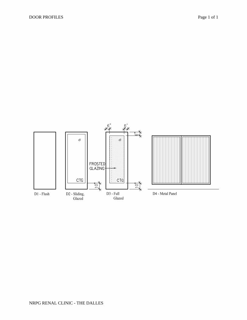
DOOR PROFILES Page 1 of 1
NRPG RENAL CLINIC - THE DALLES
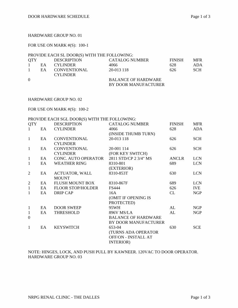
DOOR HARDWARE SCHEDULE Page 1 of 3
NRPG RENAL CLINIC - THE DALLES Page 1 of 3
HARDWARE GROUP NO. 01 FOR USE ON MARK #(S): 100-1 PROVIDE EACH SL DOOR(S) WITH THE FOLLOWING: QTY DESCRIPTION CATALOG NUMBER FINISH MFR 1 EA CYLINDER 4066 628 ADA 1 EA CONVENTIONAL
CYLINDER 20-013 118 626 SCH
0 BALANCE OF HARDWARE BY DOOR MANUFACTURER
HARDWARE GROUP NO. 02 FOR USE ON MARK #(S): 100-2 PROVIDE EACH SGL DOOR(S) WITH THE FOLLOWING: QTY DESCRIPTION CATALOG NUMBER FINISH MFR 1 EA CYLINDER 4066
(INSIDE THUMB TURN) 628 ADA
1 EA CONVENTIONAL CYLINDER
20-013 118 626 SCH
1 EA CONVENTIONAL CYLINDER
20-001 114 (FOR KEY SWITCH)
626 SCH
1 EA CONC. AUTO OPERATOR 2811 STD/CP 2 3/4" MS ANCLR LCN 1 EA WEATHER RING 8310-801
(EXTERIOR) 689 LCN
2 EA ACTUATOR, WALL MOUNT
8310-853T 630 LCN
2 EA FLUSH MOUNT BOX 8310-867F 689 LCN 1 EA FLOOR STOP/HOLDER FS444 626 IVE 1 EA DRIP CAP 16A
(OMIT IF OPENING IS PROTECTED)
CL NGP
1 EA DOOR SWEEP 95WH AL NGP 1 EA THRESHOLD 896V MS/LA AL NGP 0 BALANCE OF HARDWARE
BY DOOR MANUFACTURER
1 EA KEYSWITCH 653-04 (TURNS ADA OPERATOR OFF/ON - INSTALL AT INTERIOR)
630 SCE
NOTE: HINGES, LOCK, AND PUSH PULL BY KAWNEER. 120VAC TO DOOR OPERATOR. HARDWARE GROUP NO. 03
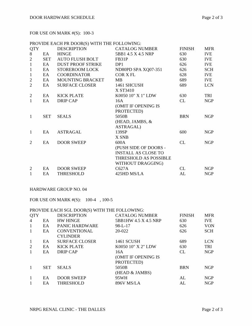
DOOR HARDWARE SCHEDULE Page 2 of 3
NRPG RENAL CLINIC - THE DALLES Page 2 of 3
FOR USE ON MARK #(S): 100-3 PROVIDE EACH PR DOOR(S) WITH THE FOLLOWING: QTY DESCRIPTION CATALOG NUMBER FINISH MFR 8 EA HINGE 5BB1 4.5 X 4.5 NRP 630 IVE 2 SET AUTO FLUSH BOLT FB31P 630 IVE 1 EA DUST PROOF STRIKE DP1 626 IVE 1 EA STOREROOM LOCK ND80PD SPA XQ07-351 626 SCH 1 EA COORDINATOR COR X FL 628 IVE 2 EA MOUNTING BRACKET MB 689 IVE 2 EA SURFACE CLOSER 1461 SHCUSH
X ST3410 689 LCN
2 EA KICK PLATE K0050 10" X 1" LDW 630 TRI 1 EA DRIP CAP 16A
(OMIT IF OPENING IS PROTECTED)
CL NGP
1 SET SEALS 5050B (HEAD, JAMBS, & ASTRAGAL)
BRN NGP
1 EA ASTRAGAL 139SP X SNB
600 NGP
2 EA DOOR SWEEP 600A (PUSH SIDE OF DOORS - INSTALL AS CLOSE TO THRESHOLD AS POSSIBLE WITHOUT DRAGGING)
CL NGP
2 EA DOOR SWEEP C627A CL NGP 1 EA THRESHOLD 425HD MS/LA AL NGP HARDWARE GROUP NO. 04 FOR USE ON MARK #(S): 100-4 , 100-5 PROVIDE EACH SGL DOOR(S) WITH THE FOLLOWING: QTY DESCRIPTION CATALOG NUMBER FINISH MFR 4 EA HW HINGE 5BB1HW 4.5 X 4.5 NRP 630 IVE 1 EA PANIC HARDWARE 98-L-17 626 VON 1 EA CONVENTIONAL
CYLINDER 20-022 626 SCH
1 EA SURFACE CLOSER 1461 SCUSH 689 LCN 2 EA KICK PLATE K0050 10" X 2" LDW 630 TRI 1 EA DRIP CAP 16A
(OMIT IF OPENING IS PROTECTED)
CL NGP
1 SET SEALS 5050B (HEAD & JAMBS)
BRN NGP
1 EA DOOR SWEEP 95WH AL NGP 1 EA THRESHOLD 896V MS/LA AL NGP
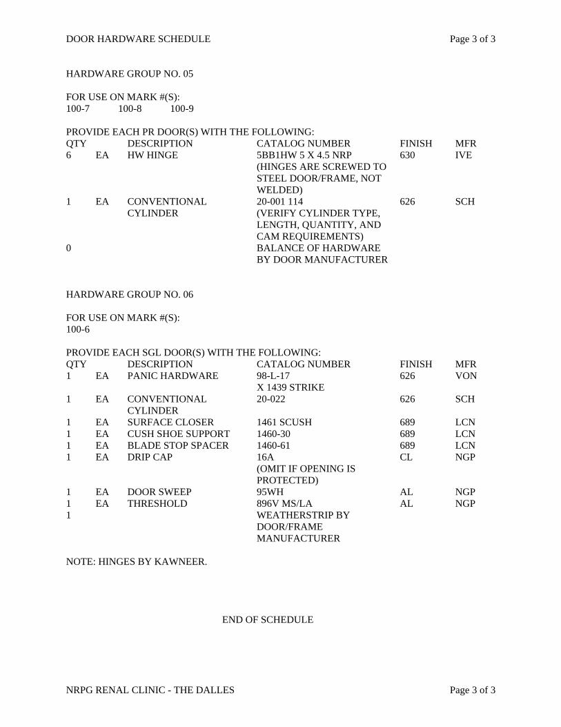
DOOR HARDWARE SCHEDULE Page 3 of 3
NRPG RENAL CLINIC - THE DALLES Page 3 of 3
HARDWARE GROUP NO. 05 FOR USE ON MARK #(S): 100-7 100-8 100-9 PROVIDE EACH PR DOOR(S) WITH THE FOLLOWING: QTY DESCRIPTION CATALOG NUMBER FINISH MFR 6 EA HW HINGE 5BB1HW 5 X 4.5 NRP
(HINGES ARE SCREWED TO STEEL DOOR/FRAME, NOT WELDED)
630 IVE
1 EA CONVENTIONAL CYLINDER
20-001 114 (VERIFY CYLINDER TYPE, LENGTH, QUANTITY, AND CAM REQUIREMENTS)
626 SCH
0 BALANCE OF HARDWARE BY DOOR MANUFACTURER
HARDWARE GROUP NO. 06 FOR USE ON MARK #(S): 100-6 PROVIDE EACH SGL DOOR(S) WITH THE FOLLOWING: QTY DESCRIPTION CATALOG NUMBER FINISH MFR 1 EA PANIC HARDWARE 98-L-17
X 1439 STRIKE 626 VON
1 EA CONVENTIONAL CYLINDER
20-022 626 SCH
1 EA SURFACE CLOSER 1461 SCUSH 689 LCN 1 EA CUSH SHOE SUPPORT 1460-30 689 LCN 1 EA BLADE STOP SPACER 1460-61 689 LCN 1 EA DRIP CAP 16A
(OMIT IF OPENING IS PROTECTED)
CL NGP
1 EA DOOR SWEEP 95WH AL NGP 1 EA THRESHOLD 896V MS/LA AL NGP 1 WEATHERSTRIP BY
DOOR/FRAME MANUFACTURER
NOTE: HINGES BY KAWNEER.
END OF SCHEDULE