Embed Size (px)
Citation preview

PERMEABILITY MEASUREMENTSOF PRESS FELTS
X. Thibault, Y. Chave, J-M. Serra-Tosioand J-F. Bloch
Laboratoire Génie des Procédés Papetiers(LGP2/ EFPG/ CTP/ CNRS UMR 5518)BP 65, 38402 Saint-Martin-d’Hères Cedex
INTRODUCTION
The main aim of the successive unit operations of the papermaking process isto remove water from the fibrous web. Water is removed mechanically duringthe forming and pressing operations. The sheet is then dried in the dryersection further along the paper machine. Classically, the necessary energy forevaporating water by drying is six times higher than the energy required toremove the same quantity of water by pressing. Consequently the more wateris removed by the forming and pressing operations, the lower the productioncosts are. Therefore, an efficient press section has a very definite influence onthe whole economy of a paper mill.
In this paper, the main developments of the press section in the last centuryare briefly presented. The evolution of pressing theory and areas of researchare discussed. In a second part, the theoretical and experimental back-grounds of flow resistance in a press felt are given. Then, the built experi-mental device is described and finally results of transverse and in-planepermeability measurements are analysed.
12th Fundamental Research Symposium, Oxford, September 2001 947
Preferred citation: X. Thibault, Y. Chave, J-M. Serra-Tosio and J-F. Bloch. Permeability Measurements of Press Felts. In The science of papermaking, Trans. of the XIIth Fund. Res. Symp. Oxford, 2001, (C.F. Baker, ed.), pp 947–974, FRC, Manchester, 2018. DOI: 10.15376/frc.2001.2.947.

LITERATURE
Pressing history
Most of the earliest paper machine press sections were equipped with plainpresses: two smooth rolls pressed the paper sheet supported by a felt (Figure1). The main drawback of this technology is that, as the paper machineproduction speed increases, the hydraulic pressure inside the press nip risesdramatically and crushing of the paper sheet may occur. To overcome thisdrawback, the water flow length in the press nip had to be decreased.Grooved and blind drilled presses were therefore major advances. In the six-ties, the fabric press and then the suction press were developed. Later, theextended nip and high impulse pressing concepts were designed, leading tothe development of modern shoe press. The latest development in pressingtechnology is the impulse pressing press (or often called impulse drying),which combines pressing and heating at high temperature. With this processthe distinction between pressing and drying is going to blur [1]. Someexamples of this technology are described through experimental trials con-ducted in the Swedish Pulp and Paper Research Institute (STFI) [2] or in theInstitute for Paper and Science Technology (IPST) [3].
In order to improve dewatering in press section, two kinds of solutionsexist. One is to radically change press design, and build a new press sectionfor example with a higher mechanical impulse (see Figure 1), i.e. a longer nipor a higher load.
Figure 1 Evaluation of the press impulse.
948 Session 5: Sensors and Measurement
X. Thibault, Y. Chave, J-M. Serra-Tosio and J-F. Bloch

The other solution is to add new devices or modify elements in the presssection: adding steam boxes, optimising the rolls or the press closing.Examples of press optimisation were described by Wheeldon and Green [4].They showed that increasing the nip load was not always the best alternativebut changing the felt could be more profitable. In the case of press clothing,the main characteristics of the felt (compressibility, uniformity of load distri-bution, flow resistance of felt structure and life expectancy) have to be welldescribed and understood. The present work deals with the determination ofpermeability (inverse of the flow resistance) in strained felts to satisfy theneed of felt manufacturers to characterise their product.
Theoretical background
Numerous studies have been made on pressing this last forty years. Wahl-ström provided a useful basis for qualitative models of wet pressing. Hepostulated, on one hand, the compressive stress has to be balanced in thepress nip by the hydraulic pressure and the structural stress. On the otherhand, the hydraulic pressure and the water flow start rising when the webbecomes saturated [5,6]. His theory has been widely accepted and has beensince qualitatively improved. First of all, a more precise flow description inthe nip is made by Asklöf [7] and next Nilsson and Larsson [8]. The rewet-ting phenomenon after the nip, which is controlled by the capillary forces,was examined by Wahlström et al. [9]. A model taking into account theinertial effects of water entering and leaving the nip, and also the dynamicshrinkage of the press nip because of the increasing rigidity of the rollclothing with faster solicitations, was proposed by Gudehus [10]. If theexplanations proposed by these authors represent major advances in press-ing theory, they did not allow any prediction of press efficiency. In his workon pressing simulation, Roux [11] underlined that the validation of a press-ing model is very difficult, if not impossible, due to the lack of measure-ments in press sections. Nowadays, some quantitative pressing models aremore effective owing to the use of laboratory pilot paper machines [12]. Themajor part of these models is based on phenomenological approaches of thewet pressed web and therefore there is an obvious need of a database forpaper and felt characteristics. In this paper only the permeability of felt willbe considered.
The Reynolds number is commonly used to study the flow through a pipeor a porous medium. This dimensionless number is defined as the ratio of theinertial to viscous terms of the Navier Stokes equation. If this number issmall, the flow is laminar (creep flow). On the contrary, if the number is high,the flow is turbulent. Classically, water flow in the press nip is characterised
12th Fundamental Research Symposium, Oxford, September 2001 949
Permeability Measurements of Press Felts

by a small Reynolds number. Consequently, the water flow may be consideredas laminar.
The analytical approach of the flow inside a porous media is very difficultbecause of the structure complexity. Early in last century, experimentalstudies lead to empirical laws relying the seepage velocity of the fluid rela-tively to the porous media and the pressure drop. When the flow through arigid porous medium is laminar, the generalised to three spatial dimensionsDarcy’s equation (Equation 1) may be applied [13].
v = −Κμ
grad(P) (1)
In this equation, v is the seepage velocity vector or volumetric flux density(in m.s−1), P the pressure field (in Pa), μ the fluid viscosity (in s−1) and K thepermeability tensor (in m2).
To rely the permeability to structural parameters, several theoretical andexperimental studies have been carried out. Among them the well-knownwork of Carman [14] leads to the following empirical formula (Equation 2):
K =ε3
koτ2Sv
2(2)
where ε is the porosity, Sv the volumic specific surface of the porousmedium (in m2/m3), τ the tortuosity and ko is a constant called the Kozeny–Carman constant. The porosity is the ratio of the void volume to effectivetotal volume of the porous web. The tortuosity is the ratio of the averagelength of the fluid flow inside the web to the apparent length of the flow. Thevolumic specific surface is the ratio of the wettable surface to the volume ofthe porous web. This relation was established for a wide range of granularand fibrous media with porosity from 0.286 to 0.574 [15]. However, theKozeny–Carman formula does not take into account the direction of the flowthrough the porous structure. Rahli [16] proposed a literature review ofempirical or theoretical works on variation of Kozeny–Carman constantwith porosity. In his study of random orientated stack of monodispersefibres, he found that the permeability-porosity relationship fitted very wellwith an exponential function inspired from Kyan work [17]. So in thepresented work, Kozeny–Carman and based-10 exponential models (seeexperimental results paragraph) are compared in the experimental results.The main asset of based-10 exponential function on exponential one isthat the order of magnitude is quite easily found. In the last two described
950 Session 5: Sensors and Measurement
X. Thibault, Y. Chave, J-M. Serra-Tosio and J-F. Bloch

works, the porosity is evaluated from the basis weight. In our study, thefollowing notation is used for porosity evaluation: basis weight w (kg/m2),the density of the fibres ρf (kg/m3); and the thickness e (m). The classicalrelationship is:
ε = 1 −w
e·ρf
(3)
In the context of this study, the porous media is a felt and its porosityduring pressing is often lower than the porosity range of Kozeny–Carmanlaw. Therefore the applicability of this law is not obvious.
Biot [18] and Auriault [19] discussed and proved the validity of the Darcy’slaw for non-saturated deformable porous media. It remains from their worksthat this law is also applicable in the case of linear elastic behaviour withsmall deformation and immiscible two-phase flow. Auriault [20] generalizedthe homogenization techniques of locally periodic porous media to randomones. Homogenized approach is the description of the continuous mediaequivalent to the complex description of the media with all the microscopicheterogeneities. The main assumption for applying this method is a goodseparation of the microscopic and the macroscopic scales of the problem.Hence, the permeability tensor depends only of the geometrical character-istics of the structure and if this geometry is known direct evaluation of thepermeability is possible.
EXPERIMENTAL REVIEW
Only a few experimental studies on press felt permeability have been pub-lished. Macklem [21] studied the flow resistance of wool felts in transverseand lateral directions. He showed that Kozeny–Carman equation coulddescribe the flow through press felts. However the Kozeny–Carman constant,ko would not be the same for transverse or lateral flows. Kershaw [22] studiedthe flow resistance of felts in three directions. The in-plane one was roughlyisotrope for all tested felts. In these works, the lateral permeability was higheror equal to the transverse one. Ballard [23] studied the permeability of100% synthetics felts. He found that felt with monofilament base offeredsuperior permeability under load than other type of tested felts. Chevallier[24] pointed out that felt permeability is tension stress dependent. All ofthese authors used a unidirectional flow device to measure the in-plane per-meability. To measure transverse permeability, the flow direction is usually inthe direction orthogonal to the felt plane. A linear relationship between the
12th Fundamental Research Symposium, Oxford, September 2001 951
Permeability Measurements of Press Felts

pressure gradient and the seepage velocity is found in each experimental workthat may lead to the permeability computation. Nowadays, industrial felt per-meability measurement equipment exists [25]. These permeability measure-ments consist in imposing the pressure drop and measure the flow ratethrough a known section. However, it can be used only on non-strained felt.
Nevertheless, in the textile research field (fibre reinforcement), manyexperimental studies of the in-plane permeability of woven and non-woventextiles were done using unidirectional or radial flow devices (Figure 2).Radial flow consists in injecting a fluid in the centre of the saturated orunsaturated sample and studies the progress of the flow front. Usually, thismethod allows the determination of the principal axes of the permeabilitytensor. Parnas [26,27], compared the measurement of flow resistance withboth device. He found close results for different woven glass materials whichporosities ranged from 45% to 80%. Young [28], studied the average in-planepermeability–compression dependence with the radial flow method. Hisresults showed non-linearity attributed to the woven web deformations. Fur-themore, permeability as a function of porosity fits very well with anexponential relationship. Lekakou [29] compared the measurement of theaverage in-plane permeability using unidirectional and radial techniques.
Figure 2 Schema illustrating the principles of unidirectional and radialpermeameters.
952 Session 5: Sensors and Measurement
X. Thibault, Y. Chave, J-M. Serra-Tosio and J-F. Bloch
Permeability values obtained with the unidirectional method were one orderof magnitude higher than with the values measured with the other method.In both cases, the decrease of permeability with the decrease of porosity wasverified with Kozeny–Carman law. However, in the case of the radial flowexperiments, if the progression of the flow front was well described with theDarcy’s law, the permeability values were paradoxically dependent of theinjected flow rate. Gebart [30] compared the radial and the unidirectionalflow methods. He showed that both method results are similar. Nevertheless,the radial flow techniques may have large error if the mold is not stiff enough(deformation of the measurement cell). He proposed a multi-cavity parallelflow apparatus in order to improve the unidirectional flow technique.Experimental results with this equipment showed excellent repeatability [31]and reproducibility [32] with woven and non-woven glass fiber. This repeat-ability is limited by the natural variance of the tested media. Lundströmnoticed that the anisotropy increase when the porosity decrease. The porosityrange was from 70% to 50%, permeability range from 150 μm2 to 17 μm2 andthe anisotropy ratio from 1 to 10. The author found small differences inpermeability value when using saturated and non saturated flow. In an erroranalysis, he showed that when the anisotropy ratio increase, so the error does.In order to improve the measurements, the shape of the unidirectional per-meability cell has to verify that the flow length–flow wide ratio is higher thanthe anisotropy ratio.
DESCRIPTION OF THE NEW EXPERIMENTAL DEVICE.
The new experimental device (Figure 3) imposes a flow either perpendicularto the felt plane, or in an imposed in-plane direction in order to measure theDarcian permeability in that direction. The ultimate aim is to be able toperform easy, on-machine measurements on a press felt during machinestops. This objective, conjugated to the requirement of avoiding adventitiousfelt strains, led to the decision not to use any sealing in the felt plane. Thuslateral leakage may exist. A guard area is therefore used in order to measureonly the flow that is not influenced by this potential leakage.
Case of the transverse permeability
Description of the experimental device
In the case of transverse permeability measurement, the flow is measured in acircular area of 57 mm large. The total measurement cell diameter is 120 mm.
12th Fundamental Research Symposium, Oxford, September 2001 953
Permeability Measurements of Press Felts

Porous plates are used in order to homogenize the flow and the imposedstress. For the pressure drops from 0 to 15 kPa, three constant head tankscreate the flow. The two downstream ones are always at the same height (seeFigure 3). The error on pressure drop measurements is about 20 Pa.
A pneumatic jack can load mechanically the permeameter cell (see Figure3) up to 5.5 MPa. A displacement transducer (LVdT) measures the positionof the upper part with an accuracy of 10 μm. An external stress (tension inone direction in the plane of the felt) may be applied to the felt duringmeasurements.
Weighing and timing with measurements accuracy of 5 g and 1 s respect-ively, are used to calculate the flow rate. The temperature, T (°C) is measuredwith an alcohol thermometer. The accuracy is about 0.5°C. The viscosity, μ(Pa.s−1) is evaluated with the following Bingham formula in which the tem-perature is in degree Celsius:
μ =0.1
(2.1482 · ((T − 8.8432) + (8078.4 + (T − 8.435)2)1/2) − 120)(4)
An example of numerical simulation of flow through both porous disksand a felt is presented in Figure 4. The numerical problem is considered to beaxisymmetric. On the upper part, the pressure condition is set to 1.18 bar(i.e., 1 atmosphere and 80 cm column of water). Under the down part, pres-sure is imposed to be 1.08 bar (i.e. one atmosphere minus 20 cm column ofwater). Outside pressure condition is set to 1.1 bar (1 atmosphere). Thevelocity field reveals that the outside pressure drop does not influence the flow
Figure 3 Schematic diagram of permeameter equipment.
954 Session 5: Sensors and Measurement
X. Thibault, Y. Chave, J-M. Serra-Tosio and J-F. Bloch

in the central zone. More details concerning the method of design are pre-sented in [33,34].
Experimental procedures
Felt samples are saturated in water 24 hours before the experiments. Beforeany measurement, the cell is compressed without sample in order to deter-mine the mechanical deformation of the experimental equipment forimposed stresses.
When measuring transverse permeability, the device is first calibrated. Thisstep of calibration consists in the evaluation of the pressure drop–flow raterelationship of the apparatus without a felt sample. No variation of theporous disks permeability was noticed whatever the loading stresses were.Afterwards, a felt sample is introduced into the cell, which is loaded to achosen stress level. After the felt creep (15 or 20 minutes), the pressure drop–flow rate relationship is evaluated. For each measurement of flow rate, the
Figure 4 Simulation of the flow in a half cross section of the transverse permeametre.Arrows represent the velocity field.
12th Fundamental Research Symposium, Oxford, September 2001 955
Permeability Measurements of Press Felts

temperature is measured. The Darcian permeability is then deduced using thecalibration. The linearity, and thus the validity of Darcy’s law, is checked forall measurements. The pressure drop (ΔP) versus modified flow rate (μQ)relationship is obtained with a least square regression method. Thus, tem-perature variations, that may occur for successive measurements, are takeninto account. The uncertainty range is computed for each permeability evalu-ation. Details of this calculation are shown in Annexe I.
Case of the in-plane permeability
Description of the experimental device
In the case of in-plane measurements, slit plates replace porous disks inorder to impose an in-plane unidirectional flow. The fluid arrives through two
Figure 5 Simulation of the flow in a elevation section of the in-plane permeametre.Arrows represent the velocity field.
956 Session 5: Sensors and Measurement
X. Thibault, Y. Chave, J-M. Serra-Tosio and J-F. Bloch

parallel slits (inlets) and leaves by a central one (outlet) (see Figure 5). Thetwo upstream inlets are symmetrically positioned in respect of the down-stream outlet. An example of flow computation in the felt is shown hereafterin Figure 5. Outside pressure is set to atmospheric condition (1.1 bar). Externslits pressure is set to 1.2 bar. The central slit one is set to 1 bar. This numer-ical result shows that the flow is not affected by outside pressure condition ina 30 mm large central zone.
In order to take into account the potential influence of the transversepermeability, the flow was computed in the half cross section perpendicularto the slits (Figure 6). The problem is described as symmetrical respectively tothe ordinate axe. The model results show that the flow is mostly horizontalbetween the slit and leakage of water to the outside is not predominant.Hence, if necessary in-plane measured values may be corrected by the know-ledge of the transverse permeability. In this simulation pressure conditions
Figure 6 Simulation of the flow in a half cross section of the in-plane permeametre.Arrows represent the velocity field.
12th Fundamental Research Symposium, Oxford, September 2001 957
Permeability Measurements of Press Felts

are identical to computation boundaries conditions considered in thetransversal case.
For the same levels of pressure drop, flow rates are expected smaller thanwith the transverse permeameter characteristics). Therefore, the used pres-sure drop ranges from 10 kPa to 250 kPa in order to obtain a measurable flowrate. Current water network is connected instead of the upstream tanks. Elec-tronics and mechanical equipments remain the same as for the transversepermeameter design, except for the upstream pressure, which is measured byan analogical manometer with an accuracy of 5 kPa.
Experimental procedure
The procedure to measure the in-plane permeability in respect of the feltstrain is similar to the transverse permeability measurement one, except thefirst calibration step. Due to large head loss created by the felt sample, there isno need for calibrating the empty device. The detail of the calculation of theuncertainty range on the measurements is shown in Annexe I.
EXPERIMENTAL RESULTS
All performed experiments were run with current water. Preliminary trialswere made to test the procedure [33,34]. We focused our attention on theguard ring efficiency, the sample preparation and the representativity of thetested sample. Initial trials were conducted using samples, which were satur-ated and desaerated, and other, which were only simply saturated. No signifi-cant difference was notice. Therefore next experiments were conducted withsaturated sample. Some trials were conducted with and without lateral leak-age. The results of this set of experiments demonstrate the efficiency of theguard area concept on the lateral boundary of the felt. In the case of trans-verse permeability, trials had been made with one and two stacked samplestaken from a single felt. The results reveal that, the transverse permeabilitymeasurements are not affected by the interface between the porous disks andthe felt sample. Consequently, the measured permeability values are intrinsic.
Generally, felt samples come from the clipping of felt making. Hencebecause of the edge effects due to manufacturing, its structure may presentimportant variation (for example variation of basis weight). This could pro-vide permeability variation measurements. Compacting the felt samplesbefore the permeability measurement was not done. Therefore, tested felt areuncompressed felts. The main characteristics values of tested felt sample aresummed up in the Table 1.
958 Session 5: Sensors and Measurement
X. Thibault, Y. Chave, J-M. Serra-Tosio and J-F. Bloch

Tab
le1
Tes
ted
felt
pro
pert
ies.
Sam
ple
Bas
is W
eigh
tB
ase
Bat
tB
ase
yarn
sdi
amet
erB
att
fibre
s av
erag
edi
amet
erkg
/m2
mm
μm
S-1
1600
890
710
Two
base
wea
ves
(1)
MD
6×
0.20
(2)
CM
D 0
.30
40
S-2
1350
650
700
Two
base
wea
ves
MD
4×
0.20
CM
D 0
.25
51
S-3
1230
420
810(
3)Si
ngle
bas
ew
eave
MD
6×
0.20
CM
D 0
.40
31
12th Fundamental Research Symposium, Oxford, September 2001 959
Permeability Measurements of Press Felts

Trials were done to study the evolution of permeability after a few com-pression cycles. The results of these experiments reveal that, the order ofmagnitude permeability is not affected by the three successive compressions.Therefore, repeatability could be studied in the first cycle of felt compression.Similar results were found by Chevallier [24]. Nevertheless, he showed thatsignificant permeability decrease appear after 50 cycles of compression to 10MPa. Other authors, among them Lopez [35] pointed out that the felt prop-erty modification with compression cycles highly depends on maximumreached stress.
Permeability depends only on felt structure. Felt porosity is a scalar reflect-ing the ability of the structure to stock water and it is the easiest structuralparameter to get. Thus, permeability (μm2) data are represented as a functionof the porosity for different set of experimental (Figures 7 to 12). In thefollowing figures, the cross under the experimental points represents theuncertainty range of the measurement method. The corresponding experi-mental data are shown in Annexe II.
In Kozeny–Carman formula (see Equation 2), the volumic specific Sv sur-face may be expressed in respect of Sm the mass specific volume of the web,ρf the density of yarns and fibres, and ε the porosity (Equation 5).
Sv = ρf Sm(1 − ε) (5)
Hence the Equation 2 may be rewritten:
K =1
koτ2(ρf Sm)2
·ε3
(1 − ε)2(6)
Experimental results are fitted with Kozeny–Carman formula and anexponential regression. In the case of Kozeny–Carman formula, experimentaldata are fitted with the porosity term (see Equation 6). The tortuosity τ andthe mass specific surface Sm are assumed as constant (no strain dependency).In Equation 4, the mass specific surface of the web is considered as the sumof the mass specific surface of the components. The value of the parameter(koτ
2ρfS2m)−1 is shown in Annexe II. This parameter influences only the vertical
position of the fit curve. The slope of the curve is imposed by the porosityterm.
Exponential phenomenological model need two parameters (see Equation7).
K = Λ · 10Ψ·ε
(7)
960 Session 5: Sensors and Measurement
X. Thibault, Y. Chave, J-M. Serra-Tosio and J-F. Bloch

The parameter Ψ is dimensionless. In the presented figure, Ψ reflects theslope of the fitting curve. The parameter Λ(μm2) is the ordinate origin of thefitting curve. Both are summed up in Annexe II.
For each sample of felt, two figures are exposed. The first figure is dedi-cated to the transverse permeability measurements, the second to the in-planepermeability measurements.
When the porosity decreases from 0.55 to 0.32, the transverse permeabilityof felt S-1 decreases by one and a half order of magnitude (Figure 7). Bothmodels fit very well with the experimental data.
When the porosity decreases from 0.63 to 0.42, in-plane permeability offelt S-1 decreases by one order of magnitude (Figure 8). In-plane permeabil-ity seems to be isotrope. In-plane permeability is 3 or 4 times higher thantransverse one.
In the case of felt S-2, transverse permeability remains at the same order ofmagnitude when porosity decreases from 0.54 to 0.34 (Figure 9). Kozeny–Carman does not fit with the experimental data (Figure 9). The decreased ofpermeability is less than one predicted by the Kozeny–Carman model. Thepower fitting is a better model.
The S-2 in-plane permeability decreases by one order when the porosityranges from 0.54 to 0.28. In-plane permeability is in this case anisotrope. Theratio of permeability values in cross and in machine directions increases from
Figure 7 Felt S-1 transverse permeability.
12th Fundamental Research Symposium, Oxford, September 2001 961
Permeability Measurements of Press Felts

Figure 8 Felt S-1 in-plane permeability.
Figure 9 Felt S-2 transverse permeability.
962 Session 5: Sensors and Measurement
X. Thibault, Y. Chave, J-M. Serra-Tosio and J-F. Bloch

1.33 to 1.77 in respect of the porosity. The Kozeny–Carman model is notgood for the C.D. permeability data (Figure 10) whereas the model is correctfor other in-plane direction (M.D. and 45°/M.D.) (not represented in theFigure 10). The decrease of the in-plane permeability (Figure 10) in respectof the porosity is faster than in the case of the transverse one (Figure 9).However even if the gap between transverse and in-plane permeability isdecreasing, the last one remains higher.
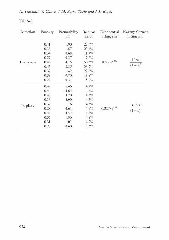
When S-3 porosity decreased from 0.46 to 0.27, the transverse permeabilitydecreased by one order of magnitude (Figure 11). S-3 transverse permeabilitybehaves like the S-1 one. Both models fit quite well the S-3 transverse data butexponential fitting is better (Figure 11). The results for transverse permeabil-ity of S-1 and S-3 samples are similar. This is the more interesting as thesefelts have very different structures (double base weave for felt S-1 and singlebase weave for felt S-3, see table 1).
The figure reveals that, during compression, S-2 felt remains quite morepermeable in the thickness direction than the two others. The transverse per-meability of S-2 has a lighter decrease than with S-1 and S-3 when porositygoes from 0.45 to 0.3. This could mean that during the compression of thesefelt S-2, no additional flow resistance appears in the thickness direction. Inexamining the Kozeny–Carman formula, this could reflect that the volumic
Figure 10 Felt S-2 in-plane permeability.
12th Fundamental Research Symposium, Oxford, September 2001 963
Permeability Measurements of Press Felts

Figure 11 Felt S-3 transverse permeability.
Figure 12 Felt S-3 in-plane permeability.
964 Session 5: Sensors and Measurement
X. Thibault, Y. Chave, J-M. Serra-Tosio and J-F. Bloch

specific surface and/or the tortuosity decrease when the felt strain decreases.In the case of S-3 felt in-plane measurements, the results in the Figure 12
are similar in three different in-plane directions. Hence the permeability ten-sor is isotrope in the plane. The orientation of the paper side batt is in thecross direction. Whereas anisotropic structure induce often anisotropic per-meability tensor, felt S-3 presents an isotropic permeability. The in-planepermeability decreases by one order of magnitude when the porosity rangesfrom 0.49 to 0.27.
CONCLUSION
The presented experimental results are in good agreements with Kershawpermeability tensor description [22]. The in-plane anisotropy remainsbetween 1 and 2 and the in-plane permeability is always higher than thetransverse one.
Contrasting with Macklem results [21], Kozeny–Carman model seems notto be an appropriate model for modelling felt permeability. In a phenomeno-logical approach, the exponential model may fit all tested felt better thanthe Kozeny–Carman formula. Nevertheless, the employed coefficients arenot related to the felt structure itself contrary to the Kozeny–Carmanparameters.
In order to optimise a given press section, a felt has to be selected. Classic-ally, this choice is made using, among others, knowledge of the unstrainedfelt transverse permeability. The apparatus described in this paper allows themeasurement of felt permeability tensor for different levels of strain. Thepresented results show that strained felt permeability tensor behaviour mightbe very different (variation of order of magnitudes, isotrope or anisotropebehaviour). Therefore, the evolution of the felt in strained state may be stud-ied and taken into account in order to optimise the efficiency of a presssection. Furthermore, the characterisation of transverse permeability willalso improve numerical models of the press.
References
1. Paulapuro, H. and Nordman, L. “Wet pressing : history and future trends”, Pulpand paper magazine of Canada, 92(1): pp 41–50 (1991).
2. Rigdahl, M., et al., “Impulse technology on the eurofex machine”. Tappi J., peerreviewed paper, 83(8): pp. 222-230 (2000).
3. Orloff, D. I., Phelan, P. M. and Crouse, J. W., “Impulse drying of board grades:Pilot production trials”, Tappi J., peer reviewed paper, 83(9) (2000).
12th Fundamental Research Symposium, Oxford, September 2001 965
Permeability Measurements of Press Felts

4. Wheeldon, J. B. and Green, A., “Improving the efficiency of the press section”.Tappi J., 55(6): pp. 889–891 (1972).
5. Wahlström, B. J., “A long term study of water removal and moisture distributionon a Newsprint machine press section – Part 2”, Pulp and paper magazine ofCanada, 9: pp. T418-T451 (1960).
6. Wahlström, B. J., “A long term study of water removal and moisture distributionon a Newsprint machine press section – Part 1”, Pulp and paper magazine ofCanada, 8: pp. T380-T401 (1960).
7. Asklöf, C. A., et al., “Flow conditions in a felt in a plain press nip”, Pulp andpaper magazine of Canada, 6: pp. T246-T250 (1964).
8. Nilsson, P. and Larsson, K. O., “Paper web performance in a press nip”, Pulp andpaper magazine of Canada, 20(12): pp. 66–73 (1968).
9. Wahlström, B. J., Johnson, A. and a. co., “Our present understanding of thefundamentals of pressing”, Pulp and paper magazine of Canada, 70(19): pp. 76–96(1969).
10. Gudehus, T., “Stoffentwässerung im Walzenpresspalt (L’essorage de la feuille depapier dans la zone de contact entre les rouleaux de presse)”, Das Papier, 42(4, 5,7) (1988).
11. Roux, J. C., “Modélisation et optimisation du fonctionnement des presses demachines à papier”, APII Fonctionnement des presses de machine à papier, (3)23(1989).
12. Gustafsson, J.-E. and Kaul, V., “A general model of wet pressing”, in Progress inpaper physics : a seminar. Grenoble (2000).
13. Scheidegger, A. E., “The physics through porous media”, Third edition, U. o. T.press, Toronto (1974).
14. Carman, P. C., “Fluid flow through granular beds”, Trans. Institute chemicalengineering, pp. 150–166 (1937).
15. Han, S. T., “Compressibility of fibre mats”, Pulp and paper magazine of Canada,T. 1(5) (1969).
16. Rahli, O., et al., “Etude expérimentale des écoulements darcéens à travers un litsde fibres empilées aléatoirement : influence de la porosité”, Journal de Phyique Il,11: p. 1739–1756 (1995).
17. Kyan, C. P., “Flow of single phase through fibrous beds”, Industrial engineerchemical fundamental, 9(4) (1970).
18. Biot, M. A., “Mechanics of deformation and acoustic propagation in porousmedia”, Journal of Applied Physics, 33(4): pp. 1482–1498 (1962).
19. Auriault, J.-L., “Nonsaturated deformable porous media: Quasistatics’ Transportin porous media, 2: pp. 45–64 (1987).
20. Auriault, J.-L., Cherel, L. and Bonnet, G., “Locally periodic medium and hom-ogenization of random media”. Arch. Mech, 40: pp. 529–542 (1988).
21. Macklem, J. E., “A study of the resistance of woven wool felts to liquid flow”,Tappi J., 44(8): pp. 535–544 (1961).
22. Kershaw, T. N., “The three dimensions of water flow in press felts”, Tappi J.,55(6): pp. 880–887 (1972).
23. Ballard, J. Press felt characterization. in Engineering conference. 1986. Atlanta.
966 Session 5: Sensors and Measurement
X. Thibault, Y. Chave, J-M. Serra-Tosio and J-F. Bloch

24. Chevallier, P. and Silvy, J., “La perméabilité directionnelle des feutres de presseshumides”, La papeterie, (5) (1988).
25. Pikulik, I. I., et al., “A new instrument for measuring the permeability of papermachine clothing” Tappi J., 5 (1991).
26. Parnas, R. S. and Salem, A. J., A comparison of the unidirectional and radial in-plane flow through woven composite reinforcement. Polymer composite, 1993. 14(5):pp. 383–394.
27. Parnas, R. S., et al., “Permeability characterisation. Part I: A proposed standardreference fabric for permeability”, Polymer composites 16(5): pp. 429–445 (1995).
28. Young, W.-B. and Wu, F., Permeability measurement of bidirectional woven glassfibers. Journal of reinforced plastics and composites, 14(10): pp. 1108–1120(1995).
29. Lekakou, C., et al., “Measurement techniques and effects on in-plane permeabil-ity of woven cloths in resin transfer moulding”, Composites, ed. E. Science. Vol.Part A. pp. 401–408 (1996).
30. Gebart, R. B. and Lidström, P., “Measurement of in-plane permeability of aniso-tropic fiber reinforcements”, Polymer composites, 16(5): pp. 429–445 (1966).
31. Lundström, S. T., Gebart, R. B. and Sandlund, E., “In-plane permeability meas-urments on fiber reinforcements by multi-cavity parallel flow technique”, Polymercomposites, 20(1): pp. 146–154 (1999).
32. Lundström, T. S., et al., “Measurement of the three-dimensional permeability”,Composites, ed. E. Science. Vol. Part A, pp. 29–43 (2000).
33. Thibault, X. “Permeability measurement of strained felt: Application to papermaking process”, in 8th World filtration congress, Brighton (2000).
34. Thibault, X. “Permeability measurement of strained felt: Application to papermaking process”, in IDS 2000. Noordwijkerhout (2000).
35. Lopez, S., “Etude du comportement rhéologique des feutres de machines àpapier”, in Génie des procédés, CPPA, Editor, INPG: Grenoble, p. 392 (1991).
ANNEXE I
Permeability evaluation:
The Darcy’s law is v = −Κμ
grad(P)
As presented in this paper, the seepage velocity, v is known owing to theflow rate measurement, Q. The product μQ and the pressure P are fitted witha linear regression (P(μQ)). The result is called A. Hence the transverse per-meability of the felt is:
K = � 1
Ao
−1
Am� ·
e
S
12th Fundamental Research Symposium, Oxford, September 2001 967
Permeability Measurements of Press Felts

Hereafter, ΔX represents the error or uncertainty range on the variable X.S is the cross section area of the measured flow., e is the thickness of the felt.
In the case of the in-plane permeability, the length uses to calculate thepressure gradient is the distance between slits (ls). Furthemore the surface Sdepend on the thickness. Thus, the permeability is:
K = � 1
Am� ·
e
S
Error evaluation on measurements
Error on pressure reading:Reading on a vertical axes : ΔP 1 mm CE or 10 Pa. Thus the uncertainty rangeon the pressure drop is 20 Pa.Error on flow rate measurement:Weighing (mass, M) and timing (time, t): ΔM is 5g and Δt 1 sError on temperature reading:Reading on an alcohol thermometer: 0.5°CError on thickness acquisition:LvdT displacement transducer: Δe is 20μm
Error induced by preliminary data transformation
Error on flow rate evaluation:
Q =Μt
⇒ΔQ
Q=
ΔM
M+
Δt
t
Error on the evaluation of the viscosity:Bingham formula:
μ =0.1
(2.1482 · ((T − 8.8432) + (8078.4 + (T − 8.435)2)1/2) − 120)
So the derivation of this function is
dμ
dT= 0.1 · � 2.1482 · (1 + (T − 8.435)(8078.4 + (T − 8.435)2)−1/2)
(2.1482·((T − 8.8432) + (8078.4 + (T − 8.435)2)1/2) − 120)2 �
968 Session 5: Sensors and Measurement
X. Thibault, Y. Chave, J-M. Serra-Tosio and J-F. Bloch

The error range on viscosity relatively to the temperature is:
Δμ = 0.1 · � 2.1482 · (1 + (T − 8.435)(8078.4 + (T − 8.435)2)−1/2)
(2.1482 · ((T − 8.8432) + (8078.4 + (T − 8.435)2)1/2) − 120)2 �ΔT
Δμ = 10μ2 · |2.1482 · (1 + (T − 8.435)(8078.4 + (T − 8.435)2)−1/2)|ΔT
Error on the least square methodThe relationship between μQ and P is fitted.
Sqq = �(μQ − μQ)2 Spq = �(μQ − μQ)2(P − P) A =Spq
Sqq
The differential of A is:
dA =�
�P �Spq
Sqq�dP +
�
�Q �Spq
Sqq�dQ +
�
�μ �Spq
Sqq�dμ
dA =1
Sqq
�
�P(Spq)dP +
Sqq
�
�QSpq − Spq
�
�QSqq
S2qq
dQ +Sqq
�
�μSpq − Spq
�
�μSqq
S2qq
�Sqq
�QdQ = �
N
1
2(μdQ −1N
�μdQ)(μQ − μQ)
�Sqq
�μdμ = �
N
1
2(Qdμ −1N
�Qdμ)(μQ − μQ)
�Spq
�QdQ = �
N
1
(μdQ −1N
�μdQ)(P − P)
�Spq
�μdμ = �
N
1
(Qdμ −1N
�Qdμ)(P − P)
�Spq
�PdP = �
N
1
(μQdP − �μQdP)
The errors on the different terms are:
12th Fundamental Research Symposium, Oxford, September 2001 969
Permeability Measurements of Press Felts

�Sqq
�QΔQ = �
N
1
2(μΔQ + μΔQ)(μQ − μQ)
�Sqq
�μΔμ = �
N
1
2(QΔμ + QΔμ)(μQ − μQ)
�Spq
�QΔQ = �
N
1
(μΔQ + μΔQ)(P − P)
�Spq
�μΔμ = �
N
1
(QΔμ − QΔμ)(P − P)
�Spq
�PΔP = �
N
1
(μQΔP + μQΔP)
The relative error on A is :
⎡⎢⎢⎢⎢⎢⎢⎢⎢⎢⎣
μQΔP + μQΔP
Spq
+⎤⎥⎥⎥⎥⎥⎥⎥⎥⎥⎦
ΔA
A= �
N
1
(μΔQ + μΔQ)(P − P)
Spq
+2(μΔQ + μΔQ)(μQ− μQ)
Sqq
+
(QΔμ − QΔμ)(P − P)
Spq
+2(μΔQ + μΔQ)(μQ − μQ)
Sqq
Error induced by the transverse permeability evaluation
K = � 1
Ao
−1
Am� ·
e
S⇒
ΔK
K=
Δ� 1
Ao
−1
Am�
� 1
Ao
−1
Am�
+Δe
e
S is the cross section area of the flow. It is supposed constant and welldefine.
Δ� 1
Ao
−1
Am�
� 1
Ao
−1
Am�
=Am
Am − Ao
·ΔAo
Ao
+Ao
Am − Ao
·ΔAm
Am
970 Session 5: Sensors and Measurement
X. Thibault, Y. Chave, J-M. Serra-Tosio and J-F. Bloch

We can notice here that the larger the difference between regression results,the smaller the made error.
Finally, the uncertainty range on the permeability is:
ΔK
K=
Am
Am − Ao
·ΔAo
Ao
+A0
Am − A0
·ΔAm
Am
+Δe
e
Error induce by the in-plane permeability evaluation
K = � 1
Am� ·
ls
L · e⇒
ΔK
K=
ΔAm
Am
+Δe
e
12th Fundamental Research Symposium, Oxford, September 2001 971
Permeability Measurements of Press Felts

ANNEXE II
Felt S-1
Direction Porosity Permeabilityμm2
RelativeError
Exponentialfitting μm2
Kozeny–Carmanfitting μm2
Thickness
M.D.andC.D.
0.550.520.470.450.430.410.400.390.360.350.340.320.540.510.480.450.430.400.390.37
0.630.610.570.560.550.530.480.430.41
8.004.863.062.462.171.801.641.411.100.890.770.65
10.764.843.913.112.501.911.581.22
55.3341.7326.4122.4319.2214.048.645.033.78
62.7%38.1%29.3%26.0%26.4%21.4%20.9%18.3%17.4%15.5%13.9%13.2%67.7%30.3%24.5%22.0%19.2%15.9%14.5%12.4%
4.0%3.1%4.8%5.6%3.1%3.9%9.6%
10.6%3.7%
0.188 ·103.78ε
0.167 ·104.68ε
8.6 ·ε3
(1 − ε)2
24 ·ε3
(1 − ε)2
972 Session 5: Sensors and Measurement
X. Thibault, Y. Chave, J-M. Serra-Tosio and J-F. Bloch

Felt S-2
Direction Porosity Permeabilityμm2
RelativeError
Exponentialfitting μm2
Kozeny–Carmanfitting μm2
Thickness
M.D.
C.D.
45°/M.D.
0.540.480.420.380.330.440.390.33
0.540.510.430.370.35
0.500.460.390.330.28
0.530.490.410.360.31
4.414.573.052.771.523.242.941.93
16.2912.707.133.272.54
15.5613.307.354.082.79
16.8313.087.443.751.97
32.4%36.1%28.5%28.2%17.1%28.6%28.3%21.7%
5.7%5.2%4.9%4.7%5.0%
5.8%5.4%5.1%5.1%4.6%
5.5%5.4%5.4%4.9%4.8%
0.39 · e2.10ε
0.30 · e3.81ε
0.10 · e4.14ε
0.1186 · e4.16ε
13.4 ·ε3
(1 − ε)2
43 ·ε3
(1 − ε)2
22.6 ·ε3
(1 − ε)2
30.66 ·ε3
(1 − ε)2
12th Fundamental Research Symposium, Oxford, September 2001 973
Permeability Measurements of Press Felts
Felt S-3
Direction Porosity Permeabilityμm2
RelativeError
Exponentialfitting μm2
Kozeny-Carmanfitting μm2
Thickeness
In-plane
0.410.380.340.270.460.430.370.330.29
0.490.440.400.360.320.280.440.350.310.27
1.901.670.680.274.152.851.420.700.31
6.664.653.202.091.160.614.571.961.010.60
27.4%23.6%11.4%7.5%
50.6%38.7%22.6%13.8%8.2%
4.4%4.6%4.5%4.5%4.8%4.9%4.8%4.9%4.7%5.6%
0.53 · e4.37ε
0.227 · e4.28ε
10 ·ε3
(1 − ε)2
16.7 ·ε3
(1 − ε)2
974 Session 5: Sensors and Measurement
X. Thibault, Y. Chave, J-M. Serra-Tosio and J-F. Bloch

PERMEABILITY MEASUREMENTS OFPRESS FELTS
X. Thibault, Y. Chave, J-M. Serra-Tosio, J-F. BlochLaboratoire Génie des Procédés Papetiers
Shri Ramaswamy University of Minnesota
Where did you get the surface area and tortuosity numbers to calculate theKozeny–Carman figures?
Xavier Thibault
We did not measure these numbers. We considered the first term Ac of theequation of Kozeny–Carman (Eq. i) was not strain dependant as we were notable to measure the Kozeny–Carman parameter (koτ
2).
A =1
koτ2S2
m
Equation i: Parameter of the Kozeny–Carman model
Shri Ramaswamy
So how do you calculate?
Xavier Thibault
Ac was considered as a parameter. The value of this parameter is obtained byfitting the experimental results with the model.
Shri Ramaswamy
So the slope of that equation covered the rest of the parameters.
12th Fundamental Research Symposium, Oxford, September 2001
Transcription of Discussion

Xavier Thibault
Yes, nevertheless this parameter influences more the ordinate at the originthan the slope.
Bill Sampson Department of Paper Science, UMIST
The very feature that you are looking at is the anisotropy of the flow in thefelt is due to the anisotropy of the material, but the Kozeny–Carman modeljust used porosity which is an orthotropic property of the material, and whatchanges is the organization of that porosity in different direction. I think thatis unrealistic to expect Kozeny–Carman or any other model which uses poros-ity as a variable to fit your data.
Xavier Thibault
First of all, we wanted to test the efficiency of the Kozeny–Carman model.Furthermore, the tortuosity may be considered as a directional property. Ourresults showed us that the Kozeny–Carman relationship is not adapted to takeinto account the compression dependance of felt permeability. This conclu-sion reinforces your point of view if we are considering the tortuosity as ascalar.
Next, we used the porosity not as a geometrical variable, but as a strainvariable (porosity is strain dependent) as we have the following relation(Equation ii) between the felt strain and the porosity ε considering feltcompression.
ε =1 − w
pfeEquation ii: Relation between felt thickness and its porosity.
with w, the felt basis weight, pf, the fibers and yarns density, e, the feltthickness.
Thus, we have presented the results as a function of porosity. However toillustrate your comment we present here the analyse of the porosity evolutionthrough the felt S-1 thickness (Figure 1).
This curve was calculated using the reconstructed volume slice of our X-ray microtomography measurements. The porosity is represented versus theslice number (a slice each 6.6 microns). The curve is for the felt S-1 with nostrain. As the curve starts the porosity is high because there are few fibers
Discussion
Session 5

then penetrating inside the batt the porosity decreased rapidly and theminimum is reached inside the base. This porosity behaviour may be taken into account when modeling the felt transverse permeability.
Gary Baum Institute of Paper Science & Technology
Is it your intention to use this device to design improved felts?
Xavier Thibault
First of all, we have to relate the felt structure to the physical properties.X-ray measurements have been conducted on the felt using the absorbtion
contrast technique (Thibault, X., J.-F. Bloch, and E. Boller, Tissue structurecharacterised by synchrotron microtomography. APPITA, 2001). Example ofthe 3-D construction results are shown just below for S-1 and S-3 samples(Figures 2 and 3). Pictures illustrate the felt compression. The left image repre-sents the felt with no strain. The right one is a strained state.
Figure 1 Porosity evolution towards felt thickness
Permeability Measurements of Press Felts
12th Fundamental Research Symposium, Oxford, September 2001

X-ray computed microtomography is a powerful tool for the investigationof porous media structure. This technique allows the fine description of thefibrous structure.
Figure 2 Felt S-1 reconstruction by X-ray computed microtomography
Figure 3 Felt S-3 reconstruction by X-ray computed microtomography
Session 5
Discussion