Embed Size (px)
Citation preview
PERIODIC MAINTENANCE AND MINOR REPAIR
6-29
6
EAU04035
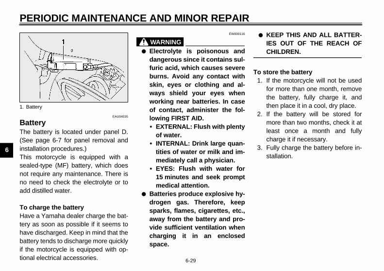
Battery The battery is located under panel D.(See page 6-7 for panel removal andinstallation procedures.)This motorcycle is equipped with asealed-type (MF) battery, which doesnot require any maintenance. There isno need to check the electrolyte or toadd distilled water.
To charge the batteryHave a Yamaha dealer charge the bat-tery as soon as possible if it seems tohave discharged. Keep in mind that thebattery tends to discharge more quicklyif the motorcycle is equipped with op-tional electrical accessories.
EW000116
WARNING_
● Electrolyte is poisonous anddangerous since it contains sul-furic acid, which causes severeburns. Avoid any contact withskin, eyes or clothing and al-ways shield your eyes whenworking near batteries. In caseof contact, administer the fol-lowing FIRST AID.• EXTERNAL: Flush with plenty
of water.• INTERNAL: Drink large quan-
tities of water or milk and im-mediately call a physician.
• EYES: Flush with water for15 minutes and seek promptmedical attention.
● Batteries produce explosive hy-drogen gas. Therefore, keepsparks, flames, cigarettes, etc.,away from the battery and pro-vide sufficient ventilation whencharging it in an enclosedspace.
● KEEP THIS AND ALL BATTER-IES OUT OF THE REACH OFCHILDREN.
_
To store the battery1. If the motorcycle will not be used
for more than one month, removethe battery, fully charge it, andthen place it in a cool, dry place.
2. If the battery will be stored formore than two months, check it atleast once a month and fullycharge it if necessary.
3. Fully charge the battery before in-stallation.
1. Battery
E_5jw.book Page 29 Friday, March 30, 2001 2:14 PM

PERIODIC MAINTENANCE AND MINOR REPAIR
6-30
6
EC000102
CAUTION:_
● Always keep the batterycharged. Storing a dischargedbattery can cause permanentbattery damage.
● To charge a sealed-type (MF)battery, a special (constant-voltage) battery charger is re-quired. Using a conventionalbattery charger will damage thebattery. If you do not have ac-cess to a sealed-type (MF) bat-tery charger, have a Yamahadealer charge your battery.
_
EAU04076*
Replacing the fuses The fuse box, which contains the fusesfor the individual circuits, is located un-der panel D. The fuel injection systemfuse box is located under panel D. Themain fuse box is also located underpanel D, beside the battery. (See page6-7 for panel removal and installationprocedures.)If a fuse is blown, replace it as follows.
1. Turn the key to “OFF” and turn offthe electrical circuit in question.
2. Remove the blown fuse, and theninstall a new fuse of the specifiedamperage.
1. Fuel injection system fuse2. Spare fuel injection system fuse
1. Headlight fuse2. Signaling system fuse3. Ignition fuse4. Windshield motor fuse5. Radiator fan fuse6. Backup fuse (odometer and clock)7. Spare fuse (× 4)
E_5jw.book Page 30 Friday, March 30, 2001 2:14 PM

PERIODIC MAINTENANCE AND MINOR REPAIR
6-31
6
EC000103
CAUTION:_
Do not use a fuse of a higher amper-age rating than recommended toavoid causing extensive damage tothe electrical system and possibly afire. _
3. Turn the key to “ON” and turn onthe electrical circuit in question tocheck if the device operates.
4. If the fuse immediately blowsagain, have a Yamaha dealercheck the electrical system.
EAU04099
Replacing a headlight bulb This motorcycle is equipped withquartz bulb headlights. If a headlightbulb burns out, replace it as follows.
1. Remove panel B (if replacing theleft headlight bulb) or panel C (ifreplacing the right headlight bulb).(See page 6-7 for panel removaland installation procedures.)
2. Disconnect the headlight coupler,and then remove the headlightbulb cover.
1. Main fuse
Specified fuses:Main fuse: 50 AHeadlight fuse: 25 ASignaling system fuse: 15 AIgnition fuse: 10 AWindshield motor fuse: 2 ARadiator fan fuse: 15 ABackup fuse (odometer and clock): 10 AFuel injection system fuse: 15 A
1. Headlight coupler2. Headlight bulb cover
E_5jw.book Page 31 Friday, March 30, 2001 2:14 PM

PERIODIC MAINTENANCE AND MINOR REPAIR
6-32
6
3. Unhook the headlight bulb holder,and then remove the defectivebulb.
EW000119
WARNING_
Headlight bulbs get very hot. There-fore, keep flammable products awayfrom a lit headlight bulb, and do nottouch the bulb until it has cooleddown. _
4. Place a new bulb into position, andthen secure it with the bulb holder.
EC000104
CAUTION:_
Take care not to damage the follow-ing parts:
● Headlight bulbDo not touch the glass part ofthe headlight bulb to keep it freefrom oil, otherwise the transpar-ency of the glass, the luminosi-ty of the bulb, and the bulb lifewill be adversely affected. Thor-oughly clean off any dirt and fin-gerprints on the headlight bulbusing a cloth moistened with al-cohol or thinner.
● Headlight lens• Do not affix any type of tinted
film or stickers to the head-light lens.
• Do not use a headlight bulb ofa wattage higher than speci-fied.
_
5. Install the bulb cover, and thenconnect the coupler.
6. Install the panel.7. Have a Yamaha dealer adjust the
headlight beam if necessary.
EAU04000
Replacing a tail/brake light bulb
1. Remove the passenger seat. (Seepage 3-10 for passenger seat re-moval and installation procedures.)
2. Remove the socket (together withthe bulb) by turning it counter-clockwise.
3. Remove the defective bulb byturning it counterclockwise.
4. Insert a new bulb into the socket,and then turn it clockwise until itstops.
5. Install the socket (together withthe bulb) by turning it clockwise.
6. Install the passenger seat.
1. Headlight bulb holder 1. Socket
E_5jw.book Page 32 Friday, March 30, 2001 2:14 PM

PERIODIC MAINTENANCE AND MINOR REPAIR
6-33
6
EAU03497
Replacing a turn signal light bulb
1. Remove the turn signal light lensby removing the screw.
2. Remove the defective bulb bypushing it in and turning it counter-clockwise.
3. Insert a new bulb into the socket,push it in, and then turn it clock-wise until it stops.
4. Install the lens by installing thescrew.
ECA00065
CAUTION:_
Do not overtighten the screw, other-wise the lens may break. _
EAU03087
Troubleshooting Although Yamaha motorcycles receivea thorough inspection before shipmentfrom the factory, trouble may occur dur-ing operation. Any problem in the fuel,compression, or ignition systems, forexample, can cause poor starting andloss of power.The following troubleshooting chartsrepresent quick and easy proceduresfor checking these vital systems your-self. However, should your motorcyclerequire any repair, take it to a Yamahadealer, whose skilled technicians havethe necessary tools, experience, andknow-how to service the motorcycleproperly.Use only genuine Yamaha replace-ment parts. Imitation parts may looklike Yamaha parts, but they are ofteninferior, have a shorter service life andcan lead to expensive repair bills.
1. Screw
E_5jw.book Page 33 Friday, March 30, 2001 2:14 PM

PERIODIC MAINTENANCE AND MINOR REPAIR
6-34
6
EAU02990
Troubleshooting charts Starting problems or poor engine performance
EW000125
WARNING_
Keep away open flames and do not smoke while checking or working on the fuel system. _
Check the fuel level inthe fuel tank.
1. FuelThere is enough fuel.
There is no fuel.
Check the compression.
Supply fuel. The engine does not start. Check the compression.
Operate the electric starter.
2. CompressionThere is compression.
There is no compression.
Check the ignition.
Have a Yamaha dealercheck the vehicle.
Remove the spark plugsand check the electrodes.
3. Ignition Wipe off with a dry cloth and correct thespark plug gaps, or replace the spark plugs.
Have a Yamaha dealer check the vehicle.
The engine does not start.Have a Yamaha dealercheck the vehicle.
Operate the electric starter.
4. BatteryThe engine turns over quickly.
The engine turns over slowly.
Dry
Wet
The engine does not start.Check the battery.
Open the throttle halfway and operatethe electric starter.
The battery is good.
Check the battery lead connections,and charge the battery if necessary.
E_5jw.book Page 34 Friday, March 30, 2001 2:14 PM
PERIODIC MAINTENANCE AND MINOR REPAIR
6-35
6
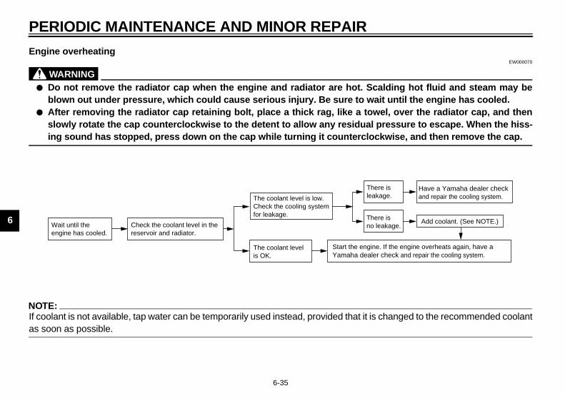
Engine overheatingEW000070
WARNING_
● Do not remove the radiator cap when the engine and radiator are hot. Scalding hot fluid and steam may beblown out under pressure, which could cause serious injury. Be sure to wait until the engine has cooled.
● After removing the radiator cap retaining bolt, place a thick rag, like a towel, over the radiator cap, and thenslowly rotate the cap counterclockwise to the detent to allow any residual pressure to escape. When the hiss-ing sound has stopped, press down on the cap while turning it counterclockwise, and then remove the cap.
_
NOTE:_
If coolant is not available, tap water can be temporarily used instead, provided that it is changed to the recommended coolantas soon as possible. _
Wait until the engine has cooled.
Check the coolant level in the reservoir and radiator.
The coolant level is OK.
The coolant level is low.Check the cooling systemfor leakage.
Have a Yamaha dealer checkand repair the cooling system.
Add coolant. (See NOTE.)
Start the engine. If the engine overheats again, have a Yamaha dealer check and repair the cooling system.
There isleakage.
There is no leakage.
E_5jw.book Page 35 Friday, March 30, 2001 2:14 PM

MOTORCYCLE CARE AND STORAGE
7
Care .................................................................................................. 7-1Storage .............................................................................................. 7-4
E_5jw.book Page 1 Friday, March 30, 2001 2:14 PM
7-1
7
EAU04069
7-MOTORCYCLE CARE AND STORAGE
Care While the open design of a motorcyclereveals the attractiveness of the tech-nology, it also makes it more vulnera-ble. Rust and corrosion can developeven if high-quality components areused. A rusty exhaust pipe may go un-noticed on a car, however, it detractsfrom the overall appearance of amotorcycle. Frequent and proper caredoes not only comply with the terms ofthe warranty, but it will also keep yourmotorcycle looking good, extend its lifeand optimize its performance.
Before cleaning1. Cover the muffler outlets with plas-
tic bags after the engine hascooled down.
2. Make sure that all caps and coversas well as all electrical couplersand connectors, including thespark plug caps, are tightly in-stalled.
3. Remove extremely stubborn dirt,like oil burnt onto the crankcase,with a degreasing agent and abrush, but never apply such prod-ucts onto seals, gaskets andwheel axles. Always rinse the dirtand degreaser off with water.
CleaningECA00010
CAUTION:_
● Avoid using strong acidic wheelcleaners, especially on spokedwheels. If such products areused on hard-to-remove dirt, donot leave the cleaner on the af-fected area any longer than in-structed. Also, thoroughly rinsethe area off with water, immedi-ately dry it, and then apply acorrosion protection spray.
● Improper cleaning can damagewindshields, cowlings, panelsand other plastic parts. Useonly a soft, clean cloth orsponge with mild detergent andwater to clean plastic.
E_5jw.book Page 1 Friday, March 30, 2001 2:14 PM

MOTORCYCLE CARE AND STORAGE
7-2
7
● Do not use any harsh chemicalproducts on plastic parts. Besure to avoid using cloths orsponges which have been incontact with strong or abrasivecleaning products, solvent orthinner, fuel (gasoline), rust re-movers or inhibitors, brake flu-id, antifreeze or electrolyte.
● Do not use high-pressure wash-ers or steam-jet cleaners sincethey cause water seepage anddeterioration in the following ar-eas: seals (of wheel and swing-arm bearings, fork and brakes),electric components (couplers,connectors, instruments, switch-es and lights), breather hosesand vents.
● For motorcycles equipped witha windshield: Do not use strongcleaners or hard sponges asthey will cause dulling orscratching. Some cleaningcompounds for plastic mayleave scratches on the wind-shield. Test the product on asmall hidden part of the wind-shield to make sure that it doesnot leave any marks. If the wind-shield is scratched, use a quali-ty plastic polishing compoundafter washing.
_
After normal useRemove dirt with warm water, a milddetergent, and a soft, clean sponge,and then rinse thoroughly with cleanwater. Use a toothbrush or bottlebrushfor hard-to-reach areas. Stubborn dirtand insects will come off more easily ifthe area is covered with a wet cloth fora few minutes before cleaning.
After riding in the rain, near the sea oron salt-sprayed roadsSince sea salt or salt sprayed on roadsduring winter are extremely corrosive incombination with water, carry out thefollowing steps after each ride in therain, near the sea or on salt-sprayedroads.
NOTE:_
Salt sprayed on roads in the winter mayremain well into spring. _
1. Clean the motorcycle with coldwater and a mild detergent, afterthe engine has cooled down.
ECA00012
CAUTION:_
Do not use warm water since it in-creases the corrosive action of thesalt. _
2. After drying the motorcycle, applya corrosion protection spray on allmetal, including chrome- and nick-el-plated, surfaces to prevent cor-rosion.
E_5jw.book Page 2 Friday, March 30, 2001 2:14 PM

MOTORCYCLE CARE AND STORAGE
7-3
7
After cleaning1. Dry the motorcycle with a chamois
or an absorbing cloth.2. Use a chrome polish to shine
chrome, aluminum and stainless-steel parts, including the exhaustsystem. (Even the thermally in-duced discoloring of stainless-steel exhaust systems can be re-moved through polishing.)
3. To prevent corrosion, it is recom-mended to apply a corrosion pro-tection spray on all metal,including chrome- and nickel-plat-ed, surfaces.
4. Use spray oil as a universal clean-er to remove any remaining dirt.
5. Touch up minor paint damagecaused by stones, etc.
6. Wax all painted surfaces.7. Let the motorcycle dry completely
before storing or covering it.
EWA00031
WARNING_
● Make sure that there is no oil orwax on the brakes or tires.
● If necessary, clean the brakediscs and brake linings with aregular brake disc cleaner or ac-etone, and wash the tires withwarm water and a mild deter-gent. Before riding at higherspeeds, test the motorcycle’sbraking performance and cor-nering behavior.
_
ECA00013
CAUTION:_
● Apply spray oil and wax spar-ingly and make sure to wipe offany excess.
● Never apply oil or wax to anyrubber and plastic parts, buttreat them with a suitable careproduct.
● Avoid using abrasive polishingcompounds as they will wearaway the paint.
_
NOTE:_
Consult a Yamaha dealer for advice onwhat products to use. _
E_5jw.book Page 3 Friday, March 30, 2001 2:14 PM

MOTORCYCLE CARE AND STORAGE
7-4
7
Storage
Short-termAlways store your motorcycle in a cool,dry place and, if necessary, protect itagainst dust with a porous cover.
ECA00014
CAUTION:_
● Storing the motorcycle in apoorly ventilated room or cover-ing it with a tarp, while it is stillwet, will allow water and humid-ity to seep in and cause rust.
● To prevent corrosion, avoiddamp cellars, stables (becauseof the presence of ammonia)and areas where strong chemi-cals are stored.
_
Long-termBefore storing your motorcycle for sev-eral months:
1. Follow all the instructions in the“Care” section of this chapter.
2. For motorcycles equipped with afuel cock that has an “OFF” posi-tion: Turn the fuel cock lever to“OFF”.
3. Fill up the fuel tank and add fuelstabilizer (if available) to preventthe fuel tank from rusting and thefuel from deteriorating.
4. Perform the following steps to pro-tect the cylinders, piston rings, etc.from corrosion.
a. Remove the spark plug caps andspark plugs.
b. Pour a teaspoonful of engine oilinto each spark plug bore.
c. Install the spark plug caps onto thespark plugs, and then place thespark plugs on the cylinder headso that the electrodes are ground-ed. (This will limit sparking duringthe next step.)
d. Turn the engine over several timeswith the starter. (This will coat thecylinder walls with oil.)
e. Remove the spark plug caps fromthe spark plugs, and then installthe spark plugs and the spark plugcaps.
EWA00003
WARNING_
To prevent damage or injury fromsparking, make sure to ground thespark plug electrodes while turningthe engine over. _
E_5jw.book Page 4 Friday, March 30, 2001 2:14 PM

MOTORCYCLE CARE AND STORAGE
7-5
7
5. Lubricate all control cables andthe pivoting points of all levers andpedals as well as of the sidestand/centerstand.
6. Check and, if necessary, correctthe tire air pressure, and then liftthe motorcycle so that both of itswheels are off the ground. Alterna-tively, turn the wheels a little everymonth in order to prevent the tiresfrom becoming degraded in onespot.
7. Cover the muffler outlets with plas-tic bags to prevent moisture fromentering them.
8. Remove the battery and fullycharge it. Store it in a cool, dryplace and charge it once a month.Do not store the battery in an ex-cessively cold or warm place (lessthan 0 °C or more than 30 °C). Formore information on storing thebattery, see page 6-29.
NOTE:_
Make any necessary repairs beforestoring the motorcycle. _
E_5jw.book Page 5 Friday, March 30, 2001 2:14 PM

SPECIFICATIONS
8
Specifications .................................................................................... 8-1Conversion table ............................................................................... 8-5
E_5jw.book Page 1 Friday, March 30, 2001 2:14 PM

8-1
8
EAU01038
8-SPECIFICATIONS
Specifications CS-01E
Model FJR1300
Dimensions
Overall length 2,195 mm
Overall width 760 mm
Overall height 1,420 mm
Seat height 805 mm
Wheelbase 1,515 mm
Ground clearance 135 mm
Minimum turning radius 3,100 mm
Basic weight (with oil and full fuel tank) 268 kg
Engine
Engine type Liquid-cooled 4-stroke, DOHC
Cylinder arrangement Forward-inclined parallel 4-cylinder
Displacement 1,298 cm3
Bore × stroke 79.0 × 66.2 mm
Compression ratio 10.8:1
Starting system Electric starter
Lubrication system Wet sump
Engine oil
Type
Recommended engine oil classification API Service SE, SF, SG or
higher
Quantity
Without oil filter cartridge replacement 3.8 L
With oil filter cartridge replacement 4 L
Total amount (dry engine) 4.9 L
-20 -10 0 10 20 30 40 50 ˚C
SAE 15W-40
SAE 20W-40
SAE 10W-40
CAUTION:
Be sure to use motor oils that do not contain anti-friction mod-ifiers. Passenger car motor oils (often labeled“ENERGY CONSERVING II”) contain anti-friction additiveswhich will cause clutch and/or starter clutch slippage, result-ing in reduced component life and poor engine performance.
E_5jw.book Page 1 Friday, March 30, 2001 2:14 PM

SPECIFICATIONS
8-2
8
Final gear oil
Type Shaft drive gear oil (Part No.: 9079E-SH001-00)
Quantity 0.2 L
Cooling system capacity (total amount) 3.3 L
Air filter Dry type element
Fuel
Type Unleaded fuel only
Fuel tank capacity 25 L
Fuel reserve amount 5 L
Spark plug
Manufacturer/model NGK / CR8E or DENSO / U24ESR-N
Gap 0.7–0.8 mm
Clutch type Wet, multiple-disc
Transmission
Primary reduction system Helical gear
Primary reduction ratio 1.563
Secondary reduction system Shaft drive
Secondary reduction ratio 2.773
Transmission type Constant-mesh 5-speed
Operation Left foot
Gear ratio
1st 2.529
2nd 1.773
3rd 1.348
4th 1.077
5th 0.929
Chassis
Frame type Diamond
Caster angle 26°
Trail 109 mm
Tires
Front
Type Tubeless tire
Size 120/70 ZR17 (58 W)
Manufacturer/model Metzeler / MEZ4B FRONT
Bridgestone / BT020FN
Rear
Type Tubeless tire
Size 180/55 ZR17 (73 W)
Manufacturer/model Metzeler / MEZ4J
Bridgestone / BT020RN
E_5jw.book Page 2 Friday, March 30, 2001 2:14 PM

SPECIFICATIONS
8-3
8
Maximum load* 208 kg
Tire air pressure (measured on cold tires)
Up to 90 kg*
Front 250 kPa (2.50 kgf/cm2, 2.50 bar)
Rear 250 kPa (2.50 kgf/cm2, 2.50 bar)
90 kg–maximum*
Front 250 kPa (2.50 kgf/cm2, 2.50 bar)
Rear 290 kPa (2.90 kgf/cm2, 2.90 bar)
High-speed riding
Front 250 kPa (2.50 kgf/cm2, 2.50 bar)
Rear 290 kPa (2.90 kgf/cm2, 2.90 bar)
* Total weight of rider, passenger, cargo and accessories
Wheels
Front
Type Cast wheel
Size 17 × MT 3.50
Rear
Type Cast wheel
Size 17 × MT 5.50
Brakes
Front
Type Dual disc brake
Operation Right hand
Fluid DOT 4
Rear
Type Single disc brake
Operation Right foot
Fluid DOT 4
Suspension
Front Telescopic fork
Rear Swingarm (link suspension)
Spring/shock absorber
Front Coil spring / oil damper
Rear Coil spring / gas-oil damper
Wheel travel
Front 135 mm
Rear 125 mm
Electrical system
Ignition system Transistorized coil ignition (digital)
Charging system
Type A.C. magneto
Standard output 14 V, 490 W@ 5,000 r/min
Battery
Model GT14B-4
Voltage, capacity 12 V, 12 Ah
Headlight type Quartz bulb (halogen)
E_5jw.book Page 3 Friday, March 30, 2001 2:14 PM

SPECIFICATIONS
8-4
8
Bulb voltage, wattage × quantity
Headlight 12 V, 60/55 W × 2
Tail/brake light 12 V, 5/21 W × 2
Turn signal light 12 V, 21 W × 4
Meter lighting 14 V, 1.12 W × 4
Neutral indicator light 14 V, 1.12 W × 1
High beam indicator light 14 V, 1.12 W × 1
Turn signal indicator light 14 V, 1.4 W × 2
Engine trouble warning light 14 V, 1.12 W × 1
Oil level warning light 14 V, 1.12 W × 1
Fuses
Main fuse 50 A
Fuel injection system fuse 15 A
Headlight fuse 25 A
Signaling system fuse 15 A
Radiator fan fuse 15 A
Ignition fuse 10 A
Backup fuse (odometer and clock) 10 A
Windshield motor fuse 2 A
E_5jw.book Page 4 Friday, March 30, 2001 2:14 PM

SPECIFICATIONS
8-5
8
EAU03941
Conversion table CS-03E
All specification data in this manual are listed in SI andMETRIC UNITS.
Use this table to convert METRIC unit values to IMPERIALunit values.
Example:
METRIC VALUE CONVERSION FACTOR
IMPERIAL VALUE
2 mm × 0.03937 = 0.08 in
Conversion tableMETRIC SYSTEM TO IMPERIAL SYSTEM
Metric unit Conversion factor Imperial unit
Torque
m·kgfm·kgfcm·kgfcm·kgf
× 7.233× 86.794× 0.0723× 0.8679
ft·lbin·lbft·lbin·lb
Weight kgg
× 2.205× 0.03527
lboz
Speed km/h × 0.6214 mi/h
Distance
kmmmcmmm
× 0.6214× 3.281× 1.094× 0.3937× 0.03937
miftydinin
Volume,Capacity
cc (cm3)cc (cm3)L (liter)L (liter)
× 0.03527× 0.06102× 0.8799× 0.2199
oz (IMP liq.)cu·inqt (IMP liq.)gal (IMP liq.)
Miscellaneouskgf/mmkgf/cm2
°C
× 55.997× 14.2234× 1.8 + 32
lb/inpsi (lb/in2)°F
E_5jw.book Page 5 Friday, March 30, 2001 2:14 PM

CONSUMER INFORMATION
9
Identification numbers ....................................................................... 9-1Key identification number .................................................................. 9-1Vehicle identification number ............................................................. 9-1Model label ........................................................................................ 9-2Motorcycle noise regulation (for Australia) ........................................ 9-2
E_5jw.book Page 1 Friday, March 30, 2001 2:14 PM
9-1
9
EAU01039
9-CONSUMER INFORMATIONEAU02944
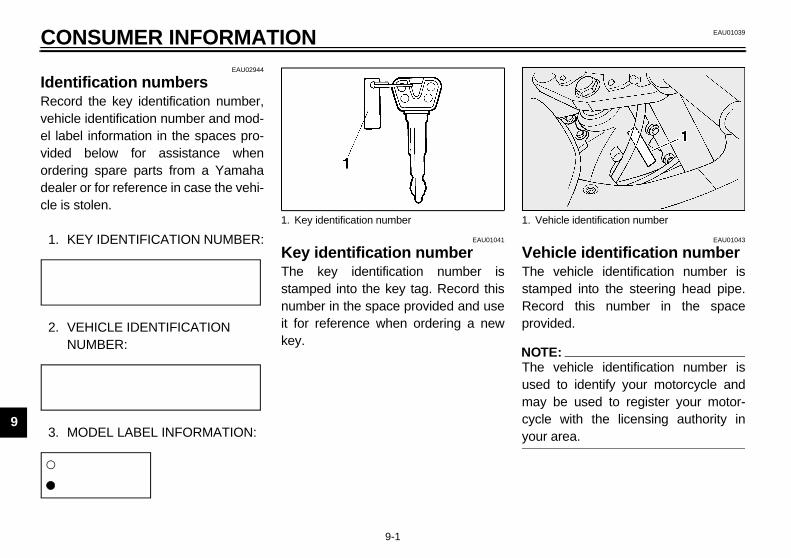
Identification numbers Record the key identification number,vehicle identification number and mod-el label information in the spaces pro-vided below for assistance whenordering spare parts from a Yamahadealer or for reference in case the vehi-cle is stolen.
1. KEY IDENTIFICATION NUMBER:CA-02E
2. VEHICLE IDENTIFICATION NUMBER:
CA-02E
3. MODEL LABEL INFORMATION:CA-01E
EAU01041
Key identification number The key identification number isstamped into the key tag. Record thisnumber in the space provided and useit for reference when ordering a newkey.
EAU01043
Vehicle identification number The vehicle identification number isstamped into the steering head pipe.Record this number in the spaceprovided.
NOTE:_
The vehicle identification number isused to identify your motorcycle andmay be used to register your motor-cycle with the licensing authority inyour area. _
1. Key identification number 1. Vehicle identification number
E_5jw.book Page 1 Friday, March 30, 2001 2:14 PM

CONSUMER INFORMATION
9-2
9
EAU01804
Model label The model label is affixed to the frameunder the rider seat. (See page 3-10 forrider seat removal and installation pro-cedures.) Record the information onthis label in the space provided. This in-formation will be needed when orderingspare parts from a Yamaha dealer.
EAU01388
Motorcycle noise regulation (for Australia) TAMPERING WITH NOISE CON-TROL SYSTEM PROHIBITED:Owners are warned that the law mayprohibit:(a) The removal or rendering inopera-
tive by any person other than forpurposes of maintenance, repairor replacement, of any device orelement of design incorporatedinto any new vehicle for the pur-pose of noise control prior to itssale or delivery to the ultimate pur-chaser or while it is in use; and
(b) The use of the vehicle after suchdevice or element of design hasbeen removed or rendered inoper-ative by any person.
1. Model label
E_5jw.book Page 2 Friday, March 30, 2001 2:14 PM

INDEX
AAir filter element, cleaning......................6-15
BBattery ...................................................6-29Brake and clutch fluid levels, checking...6-23Brake and clutch fluids, changing...........6-24Brake and clutch levers, checking and
lubricating ............................................6-25Brake and shift pedals, checking and
lubricating ............................................6-25Brake lever...............................................3-7Brake lever free play, adjusting ..............6-21Brake light switch (rear), adjusting .........6-22Brake pads, checking.............................6-22Brake pedal..............................................3-7Brake pedal position, adjusting ..............6-21
CCables, checking and lubricating............6-24Care.........................................................7-1Catalytic converter.....................................3-9Centerstand and sidestand,
checking and lubricating ......................6-26Clutch lever..............................................3-6Clutch lever free play .............................6-20Conversion table......................................8-5Coolant level, checking ..........................6-13Cowling and panels, removing and
installing ................................................6-5
DDimmer switch......................................... 3-5Display, multi-function.............................. 3-3
EEngine break-in ....................................... 5-3Engine idling speed, checking ............... 6-16Engine oil and oil filter cartridge ............... 6-9Engine stop switch................................... 3-5Engine trouble warning light .................... 3-2
FFinal gear oil.......................................... 6-12Front and rear suspension settings........ 3-15Front fork, adjusting............................... 3-11Front fork, checking ............................... 6-27Fuel ......................................................... 3-9Fuel consumption, tips for reducing ......... 5-3Fuel tank cap........................................... 3-8Fuses, replacing .................................... 6-30
HHandlebar switches ................................. 3-5Headlight bulb, replacing ....................... 6-31High beam indicator light ......................... 3-2Horn switch ............................................. 3-5
IIdentification numbers ............................. 9-1Ignition circuit cut-off system.................. 3-17Indicator and warning lights ..................... 3-2
KKey identification number .........................9-1
LLabels, location ........................................1-7Locks for optional side cases and
travel trunk...........................................3-16
MMain switch/steering lock .........................3-1Model label ..............................................9-2
NNeutral indicator light ...............................3-2Noise regulation (for Australia) .................9-2
OOil level warning light ...............................3-2
PParking.....................................................5-4Part locations ...........................................2-1Pass switch..............................................3-5Periodic maintenance and lubrication
chart ......................................................6-2Pre-operation check list............................4-1
SSafety information ....................................1-1Seats .......................................................3-9
Passenger seat.................................3-10Rider seat ...........................................3-9
Shifting.....................................................5-2Shift pedal................................................3-6
E_5jw.book Page 1 Friday, March 30, 2001 2:14 PM

INDEX
Shock absorber assembly, adjusting ..... 3-13Sidestand .............................................. 3-16Spark plugs, checking ............................. 6-8Specifications .......................................... 8-1Speedometer........................................... 3-3Starting a cold engine.............................. 5-1Start switch.............................................. 3-5Steering, checking ................................. 6-27Storage.................................................... 7-4Storage compartment ............................ 3-10Suspension (rear), lubricating ................ 6-26
TTachometer ............................................. 3-3Tail/brake light bulb, replacing ............... 6-32Throttle cable free play, adjusting .......... 6-17Throttle grip and cable, checking and
lubricating............................................ 6-25Tires ...................................................... 6-17Tool kit..................................................... 6-1Troubleshooting..................................... 6-33Troubleshooting charts .......................... 6-34Turn signal indicator lights ....................... 3-2Turn signal light bulb, replacing ............. 6-33Turn signal switch.................................... 3-5
VValve clearance, adjusting..................... 6-17Vehicle identification number ................... 9-1
WWheel bearings, checking ..................... 6-28Wheels.................................................. 6-20Windshield position adjusting switch ....... 3-5
E_5jw.book Page 2 Friday, March 30, 2001 2:14 PM

H_5KS_Toc0.fm Page 2 Monday, August 21, 2000 11:11 AM

H_5KS_Toc0.fm Page 2 Monday, August 21, 2000 11:11 AM

5JW-28199-20
FJR1300N
OWNER’S MANUAL
PRINTED ON RECYCLED PAPER
YAMAHA MOTOR CO., LTD.
PRINTED IN JAPAN2001 · 3 - 0.3 × 1 CR
(E)