Embed Size (px)
Citation preview
D e
01
/20
08
5m
a
Art
. N
r.:
79
05
77
©
Co
pyri
gh
t by P
ER
I G
mb
H
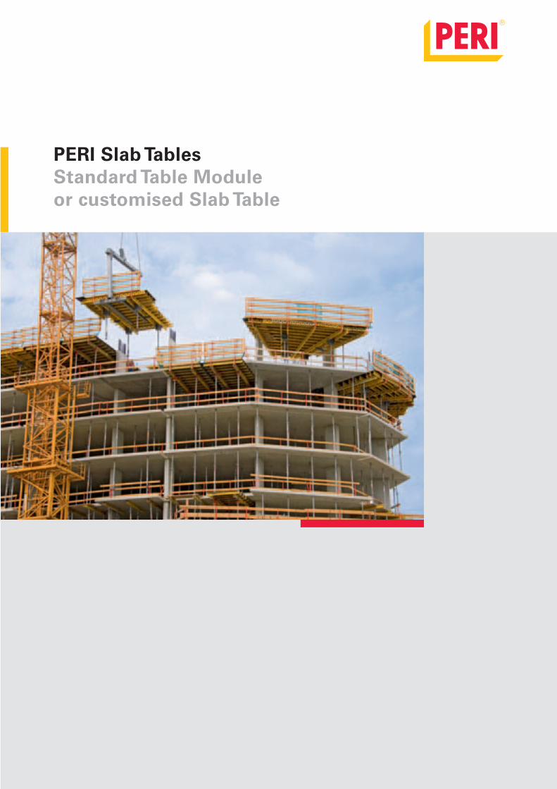
PERI Slab TablesStandard Table Module or customised Slab Table
Deckentisch_PR_e.indb 2 20.12.2007 15:24:09 Uhr
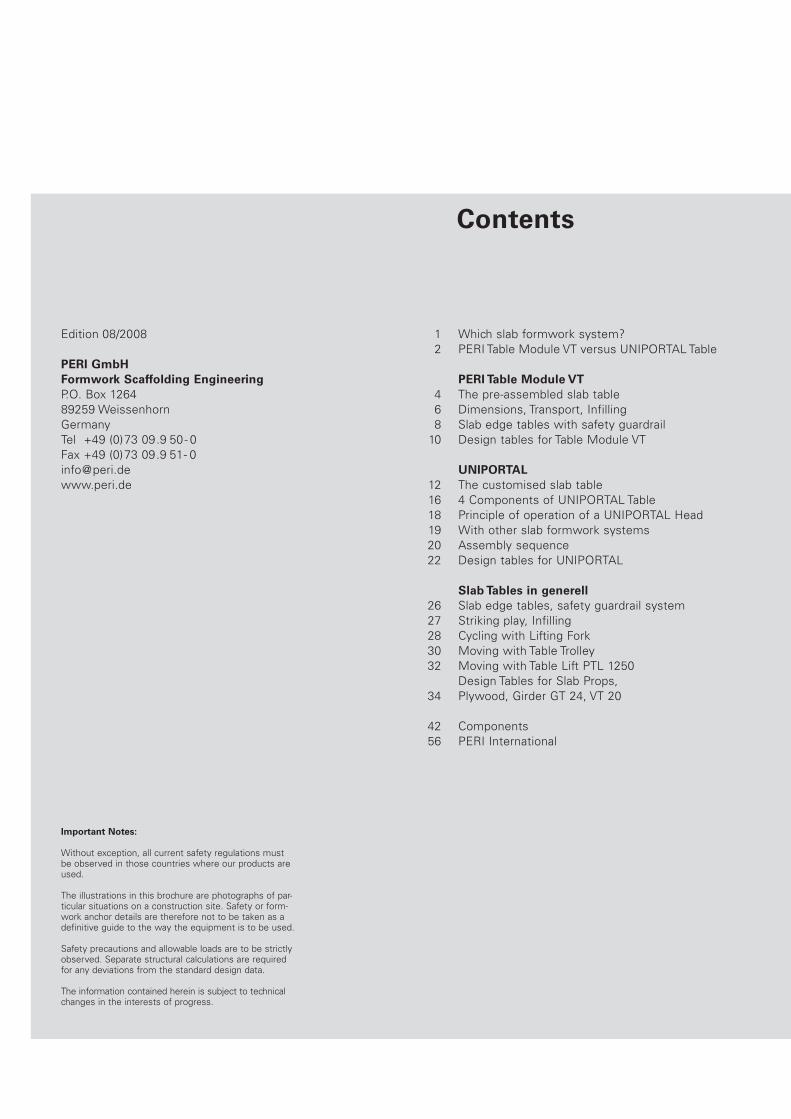
Contents
Important Notes:
Without exception, all current safety regulations must be observed in those countries where our products are used.
The illustrations in this brochure are photographs of par-ticular situations on a construction site. Safety or form-work anchor details are therefore not to be taken as a definitive guide to the way the equipment is to be used.
Safety precautions and allowable loads are to be strictly observed. Separate structural calculations are required for any deviations from the standard design data.
The information contained herein is subject to technicalchanges in the interests of progress.
PERI GmbHFormwork Scaffolding EngineeringP.O. Box 1264
89259 Weissenhorn
Germany
Tel +49 (0)73 09.9 50- 0
Fax +49 (0)73 09.9 51- 0
www.peri.de
Edition 08/2008 1 Which slab formwork system?
2 PERI Table Module VT versus UNIPORTAL Table
PERI Table Module VT4 The pre-assembled slab table
6 Dimensions, Transport, Infilling
8 Slab edge tables with safety guardrail
10 Design tables for Table Module VT
UNIPORTAL12 The customised slab table
16 4 Components of UNIPORTAL Table
18 Principle of operation of a UNIPORTAL Head
19 With other slab formwork systems
20 Assembly sequence
22 Design tables for UNIPORTAL
Slab Tables in generell26 Slab edge tables, safety guardrail system
27 Striking play, Infilling
28 Cycling with Lifting Fork
30 Moving with Table Trolley
32 Moving with Table Lift PTL 1250
Design Tables for Slab Props,
34 Plywood, Girder GT 24, VT 20
42 Components
56 PERI International
EN_Deckentisch_000-001.indd 1 19.08.2008 10:35:14 Uhr

1
2.3 28 3.450.15
–0.30
3.1 40 2.900.25
–0.50
0.05 50 5.000.10
–0.15
Which slab formwork system?
It depends on the project:
number of repetitions?
slabs repeated on successive floors?
facade sufficiently open for tables?
level of labour costs?
MULTIFLEX girder slab formwork keeps
the cost of materials down. It is there-
fore particularly cost-effective where
labour is cheap.
Given sufficent crane capacity, slab ta-
bles are the most cost-effective solution
where there is a high degree of repetition
and open facades.
SKYDECKAluminium panel slab formwork
MULTIFLEXGirder slab formwork
Table Module VT, UNIPORTALSlab tables
No. of
parts/m²
Weight
[kg/m²]
Area [m²]
per prop
Time
[h/m²]
PERI SKYDECK is generally the most
cost-effective formwork system where
labour is expensive, as in industrialised
countries.
No. of
parts/m²
Weight
[kg/m²]
Area [m²]
per prop
Time
[h/m²]
No. of
parts/m²
Weight
[kg/m²]
Area [m²]
per prop
Time
[h/m²]
Values for slab thickness d = 300 mm
EN_Deckentisch_000-001.indd 1 19.08.2008 10:35:17 Uhr

2
PERI Table Module VTwith Table Swivel Head
With the Table Swivel Head, the Table
Module VT has an overall depth of
only 430 mm. This means extremely
compact transportation and storage.
PERI Table Modules VT are therefore
particularly suitable for hiring as
standard tableforms.
The PERI Table Modules VT have fold-
ing props that are easily fitted or re-
moved. For temporary storage the
props can be easily removed.
The double main girders make inter-
mediate proping with the PERI Cross-
head simplicity itself.
The Table Swivel Head is used for slab
tables with parallel girders, such as
the Table Modules VT. It can also be
used for trapezoidal-shaped tables
and tables with radially positioned
main girders (Table Swivel Head Up-
per Part-2).
The prop can be connected from the
right or the left for folding in either
direction.
Table size
4.00 x 2.50 m.
EN_Deckentisch_002-003.indd 2 08.01.2008 11:18:19 Uhr
3
UNIPORTAL Tablewith UNIPORTAL Head
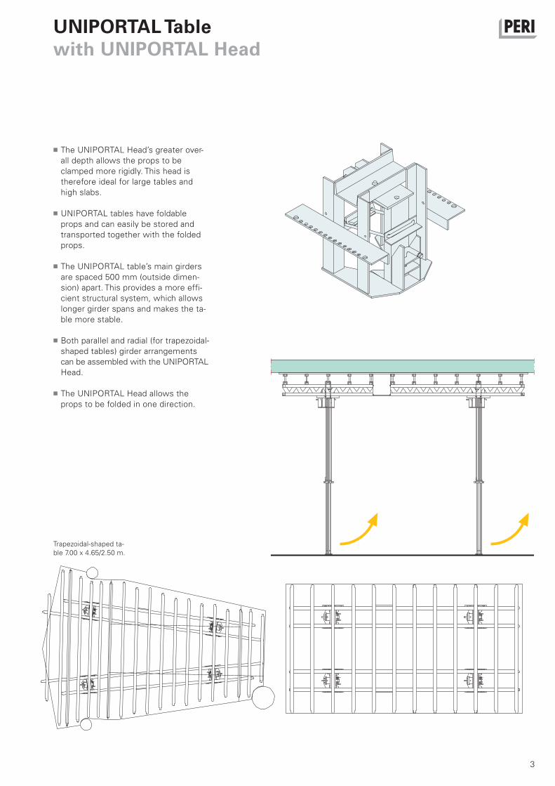
Trapezoidal-shaped ta-
ble 7.00 x 4.65/2.50 m.
The UNIPORTAL Head’s greater over-
all depth allows the props to be
clamped more rigidly. This head is
therefore ideal for large tables and
high slabs.
UNIPORTAL tables have foldable
props and can easily be stored and
transported together with the folded
props.
The UNIPORTAL table’s main girders
are spaced 500 mm (outside dimen-
sion) apart. This provides a more effi-
cient structural system, which allows
longer girder spans and makes the ta-
ble more stable.
Both parallel and radial (for trapezoidal-
shaped tables) girder arrangements
can be assembled with the UNIPORTAL
Head.
The UNIPORTAL Head allows the
props to be folded in one direction.
EN_Deckentisch_002-003.indd 3 08.01.2008 11:18:21 Uhr
4
PERI Table Module VTThe pre-assembled slab table
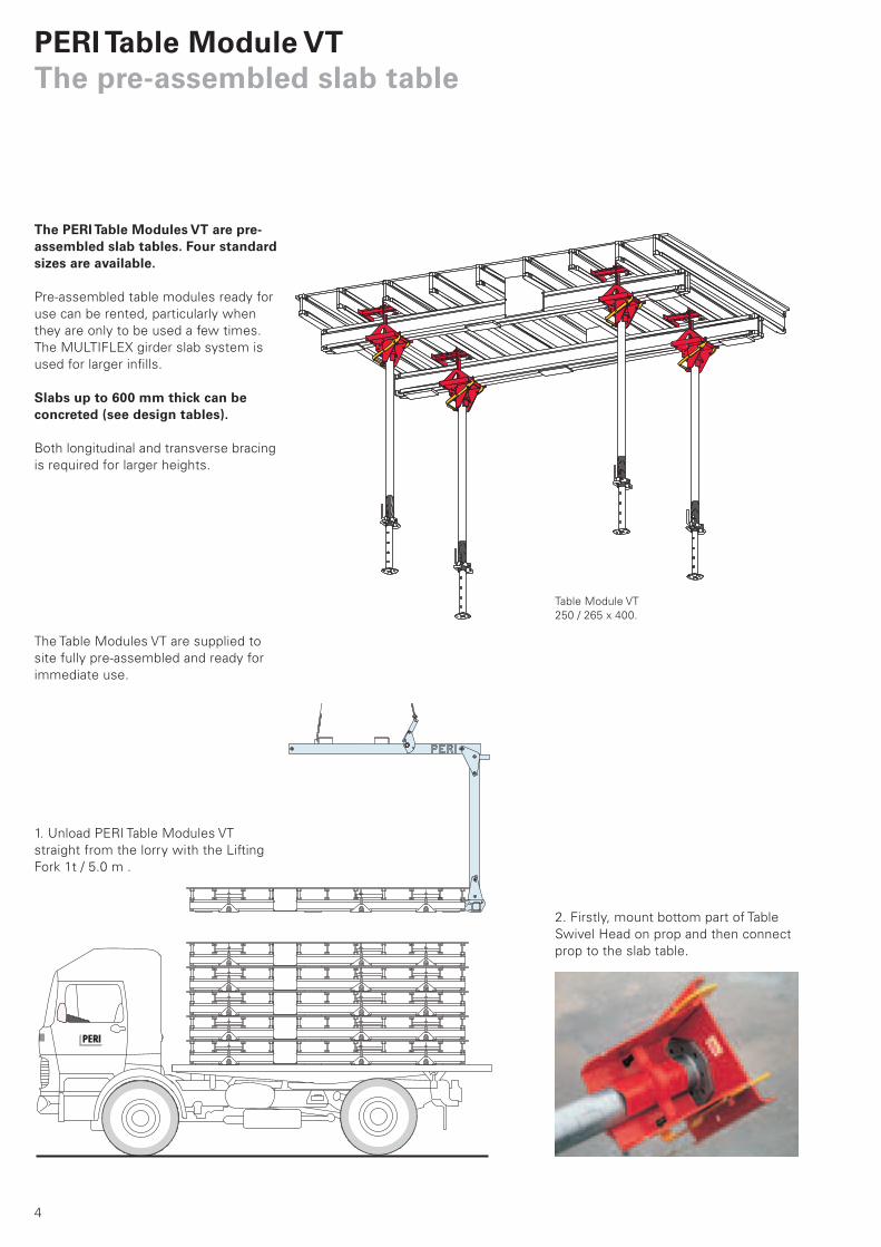
2. Firstly, mount bottom part of Table
Swivel Head on prop and then connect
prop to the slab table.
The PERI Table Modules VT are pre-assembled slab tables. Four standard sizes are available.
Pre-assembled table modules ready for
use can be rented, particularly when
they are only to be used a few times.
The MULTIFLEX girder slab system is
used for larger infills.
Slabs up to 600 mm thick can be concreted (see design tables).
Both longitudinal and transverse bracing
is required for larger heights.
Table Module VT
250 / 265 x 400.
The Table Modules VT are supplied to
site fully pre-assembled and ready for
immediate use.
1. Unload PERI Table Modules VT
straight from the lorry with the Lifting
Fork 1t / 5.0 m .
Deckentisch_PR_e.indb 4 20.12.2007 15:24:18 Uhr

5
Folding directionFolding direction
3. Connect props with Table Swivel Head
Lower Part to Table Module VT to allow
them to be folded in direction required,
and position vertically (the yellow bar se-
cures the prop). The Table Module is now
ready for use.
PERI Table Modules VT
250 / 265 x 400 used with
PEP 20 props for industri-
al building.
Deckentisch_PR_e.indb 5 20.12.2007 15:24:22 Uhr

6
0.75 0.751.15 2.35
200/215
x 400
BT 2.15 2.15 2.65 2.65
BS 2.00 2.00 2.50 2.50
LS 4.00 5.00 4.00 5.00
LT 3.90 4.90 3.90 4.90
0.75 0.752.50
BT
BS
1.500.325
0.575
0.325
0.575
7.5 cm 7.5 cm
0.4
3
7.5
cm
7.5
cm L
S = 4.00
LT = 3.90
200/215
x 500
250/265
x 400
250/265
x 500B
T
BS
LT = 4.90
LS = 4.00
LS = 5.00
LT = 3.90
PERI Table Module VTDimensions, Transport, Infilling
PERI Table Modules VT with VT 20 as main and secondary girder.
Ground plan
Longitudinal section 4.00 m tableCross-section
Longitudinal section 5.00 m table
Dimensions [m]
Table Modules VT
Sto
rag
e
he
igh
t
Deckentisch_PR_e.indb 6 20.12.2007 15:24:22 Uhr

7
*depending on slab thickness
Edge Table to tableInfilling without
additional supportInfilling with
additional supportInfilling with edge support
Compact transportation and storage.PERI Table Module VT’s overall height of
430 mm minimises storage and trans-
portation capacity. The loading width is
2.15 or 2.65 m.
Edge and width infilling.PERI Table Modules VT are very versa-
tile in use.
The Table Module’s VT
stacking height of only
430 mm allows compact
storage.
6 Table Modules VT can be stacked on
a lorry. The Lifting Fork 1.0 t / 5.0 m,
Item no 101862, is used to take them
straight to the point of use.
7.5 – 12.5 cm 15 – 25 cm 15 – 65 cm* 25 – 125 cm* 15 – 90 cm*
Deckentisch_PR_e.indb 7 20.12.2007 15:24:27 Uhr

8
1.30 m
1.4
0 m
PERI Table Module VTSlab edge tables with safety guardrail
PERI Table Modules
VT 250 / 265 x 500
with guardrail system.
Guardrail Holder GT 24 /
VT 20, Item no. 101290
and Guardrail Post SGP,
Item no. 061260.
The PERI Table Modules VT can also be used as cantilevering slab edge tables.
The Table Swivel Head is fitted to the
5.0 m Table Modul VT to enable it to be
used at the edge of the slab. The guard-
rails are pre-assembled on the ground.
2. Anchoring with chain
1. Anchoring with push-pull prop
Tension anchor to prevent
overturning, with Anchor
Chain, Item no. 065073, and
Turnbuckle, Item no. 065074.
Note:Pin ø 16 x 65 and Cot-
ter Pin 4/1 are to be
ordered separately.
Example:Table Module VT 5.0 m with guardrail
system and tension chain.
EN_Deckentisch_008-009.indd 8 08.01.2008 11:19:30 Uhr

9
Table Swivel Head folding sequenceThe props are folded out of the way in
order to negotiate parapets or down-
stand beams.
Cantilevering Table
Modules VT. The an-
choring chain is clearly
shown here.
1. Raise barA board can be used to reach higher tables
from the slab below.
2. Fold prop upThe table can now be moved out.The swivel
head’s bar re-locks when the prop is allowed to
swing down again.
EN_Deckentisch_008-009.indd 9 08.01.2008 11:19:34 Uhr
10
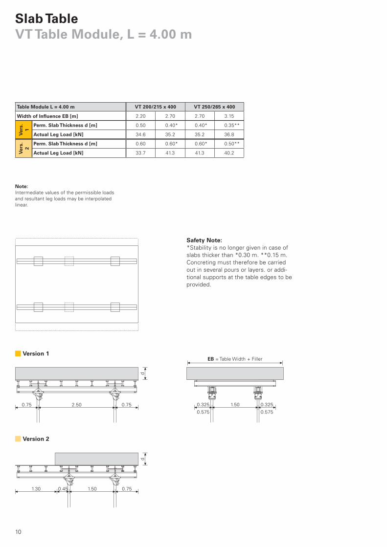
VT 200/215 x 400 VT 250/265 x 400
2.20 2.70 2.70 3.15
0.50 0.40* 0.40* 0.35**
34.6 35.2 35.2 36.8
0.60 0.60* 0.60* 0.50**
33.7 41.3 41.3 40.2
Slab TableVT Table Module, L = 4.00 m
Note:Intermediate values of the permissible loads
and resultant leg loads may be interpolated
linear.
Safety Note:*Stability is no longer given in case of
slabs thicker than *0.30 m. **0.15 m.
Concreting must therefore be carried
out in several pours or layers. or addi-
tional supports at the table edges to be
provided.
2.500.75 0.75 1.50 0.325
0.575
0.325
0.575
EB = Table Width + Filler
d
1.50 0.75
d
0.451.30
Version 1
Version 2
Table Module L = 4.00 m
Width of Influence EB [m]
Ver
s.1
Ver
s.2
Perm. Slab Thickness d [m]
Actual Leg Load [kN]
Perm. Slab Thickness d [m]
Actual Leg Load [kN]
Seite_10-11.indd 10 21.12.2007 11:31:24 Uhr

11
VT 200/215 x 500 VT 250/265 x 500
2.20 2.70 2.70 3.15
0.50 0.40* 0.40* 0.35**
34.6 35.2 35.2 36.8
0.50 0.40* 0.40* 0.35**
34.6 35.2 35.2 36.8
0.60 0.55* 0.55* 0.45**
36.0 39.9 39.9 39.9
Note:Intermediate values of the permissible loads
and resultant leg loads may be interpolated
linear.
For version 3. the Table Swivel Head must be
repositioned.
Safety Note:*Stability is no longer given in case of
slabs thicker than *0.30 m, **0.15 m.
Concreting must therefore be carried
out in several pours or layers. or addi-
tional supports at the table edges to be
provided.
2.351.30 0.75
1.50 0.325
0.575
0.325
0.575
d
0.60 0.75 0.75
d
1.85 1.65
2.350.75 0.75
d
1.15
Version 1
Version 2 Version 3
EB = Table Width + Filler
Table Module L = 5.00 m
Width of Influence EB [m]
Ver
s.1
Ver
s.2
Perm. Slab Thickness d [m]
Actual Leg Load [kN]
Perm. Slab Thickness d [m]
Actual Leg Load [kN]
Ver
s.3
Perm. Slab Thickness d [m]
Actual Leg Load [kN]
VT Table Module, L = 5.00 m
Seite_10-11.indd 11 21.12.2007 11:31:25 Uhr
12
5 c
m
5,0
0 m
ø 355.50 m
ø 70
5 cm
UNIPORTAL TableThe customised slab table
up to approx. 7.00 m
up
to
ap
pro
x.
5.0
0 m
Radius 12.80 m
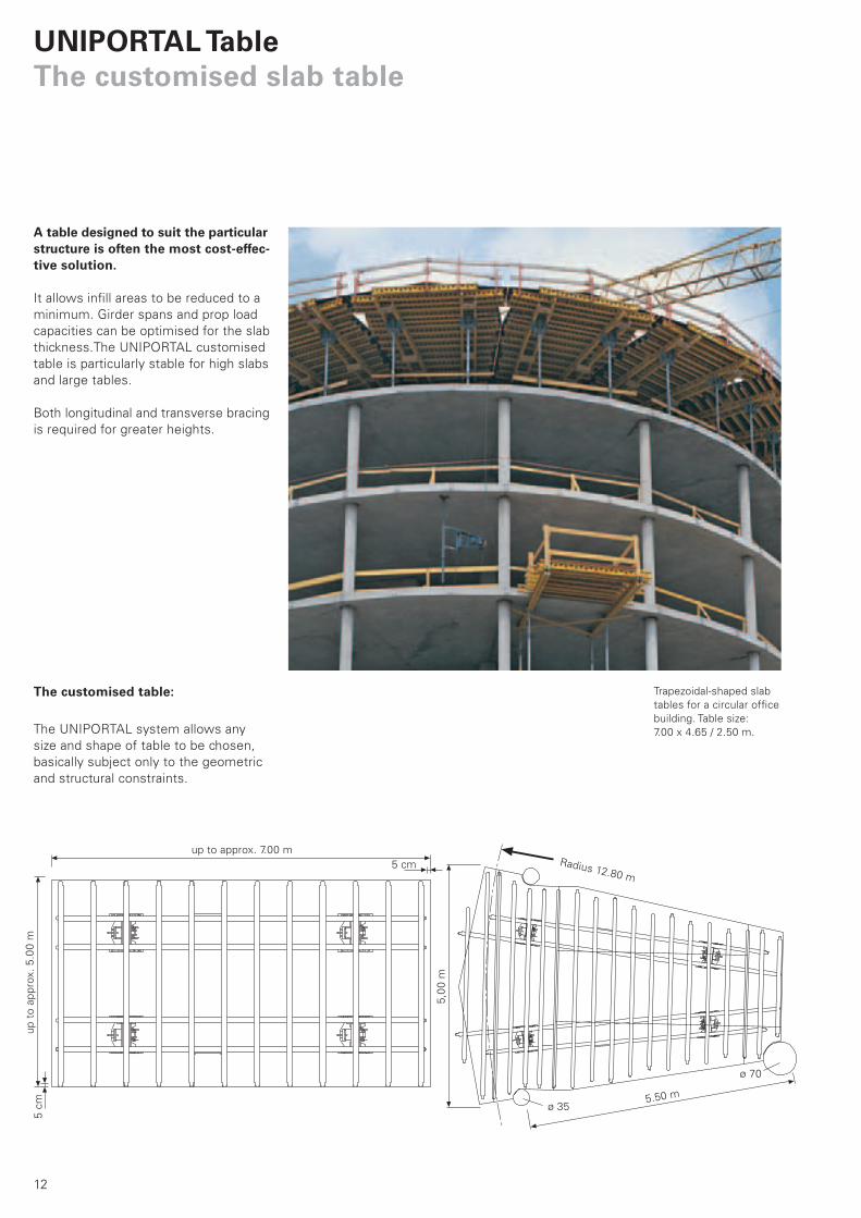
The customised table:
The UNIPORTAL system allows any
size and shape of table to be chosen,
basically subject only to the geometric
and structural constraints.
A table designed to suit the particularstructure is often the most cost-effec-tive solution.
It allows infill areas to be reduced to a
minimum. Girder spans and prop load
capacities can be optimised for the slab
thickness.The UNIPORTAL customised
table is particularly stable for high slabs
and large tables.
Both longitudinal and transverse bracing
is required for greater heights.
Trapezoidal-shaped slab
tables for a circular office
building. Table size:
7.00 x 4.65 / 2.50 m.
Deckentisch_PR_e.indb 12 20.12.2007 15:24:38 Uhr
13
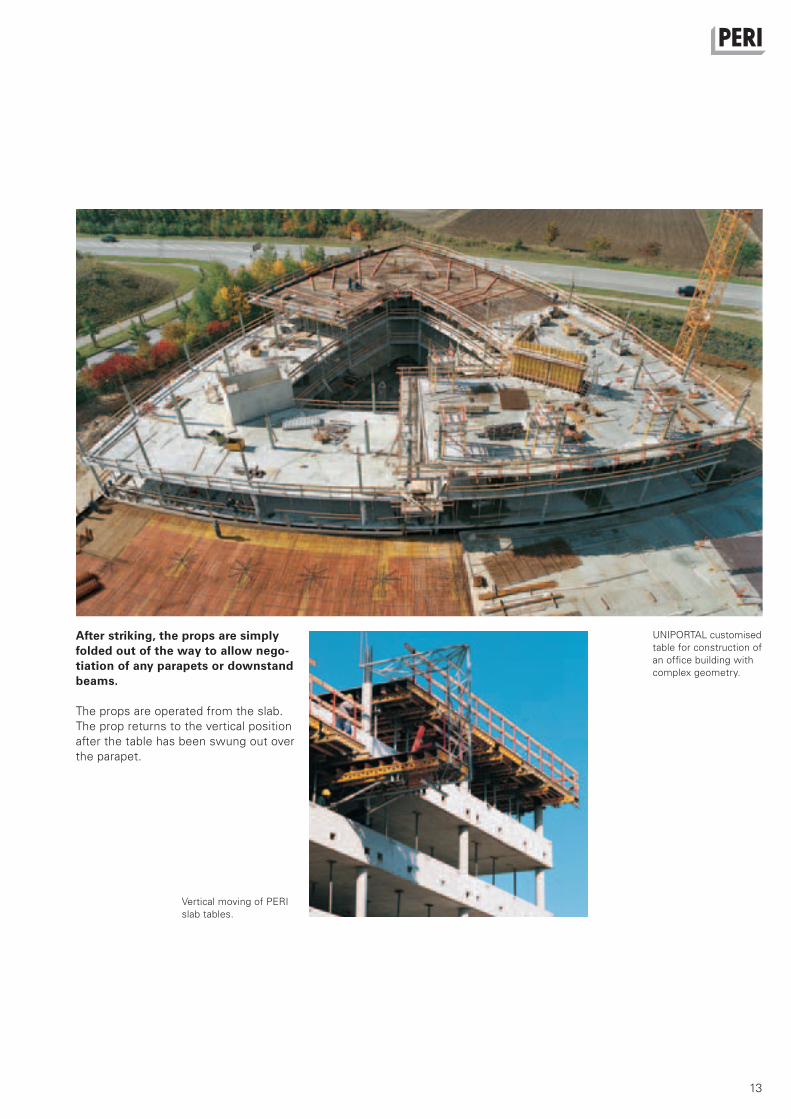
After striking, the props are simply folded out of the way to allow nego-tiation of any parapets or downstand beams.
The props are operated from the slab.
The prop returns to the vertical position
after the table has been swung out over
the parapet.
Vertical moving of PERI
slab tables.
UNIPORTAL customised
table for construction of
an office building with
complex geometry.
Deckentisch_PR_e.indb 13 20.12.2007 15:24:45 Uhr

14
UNIPORTAL TableThe customised slab table
Slab edge tables with
integrated safety guardrail
for an administration building.
Trapezoidal-shaped
UNIPORTAL slab tables for
a circular office building.
Deckentisch_PR_e.indb 14 20.12.2007 15:24:56 Uhr
15
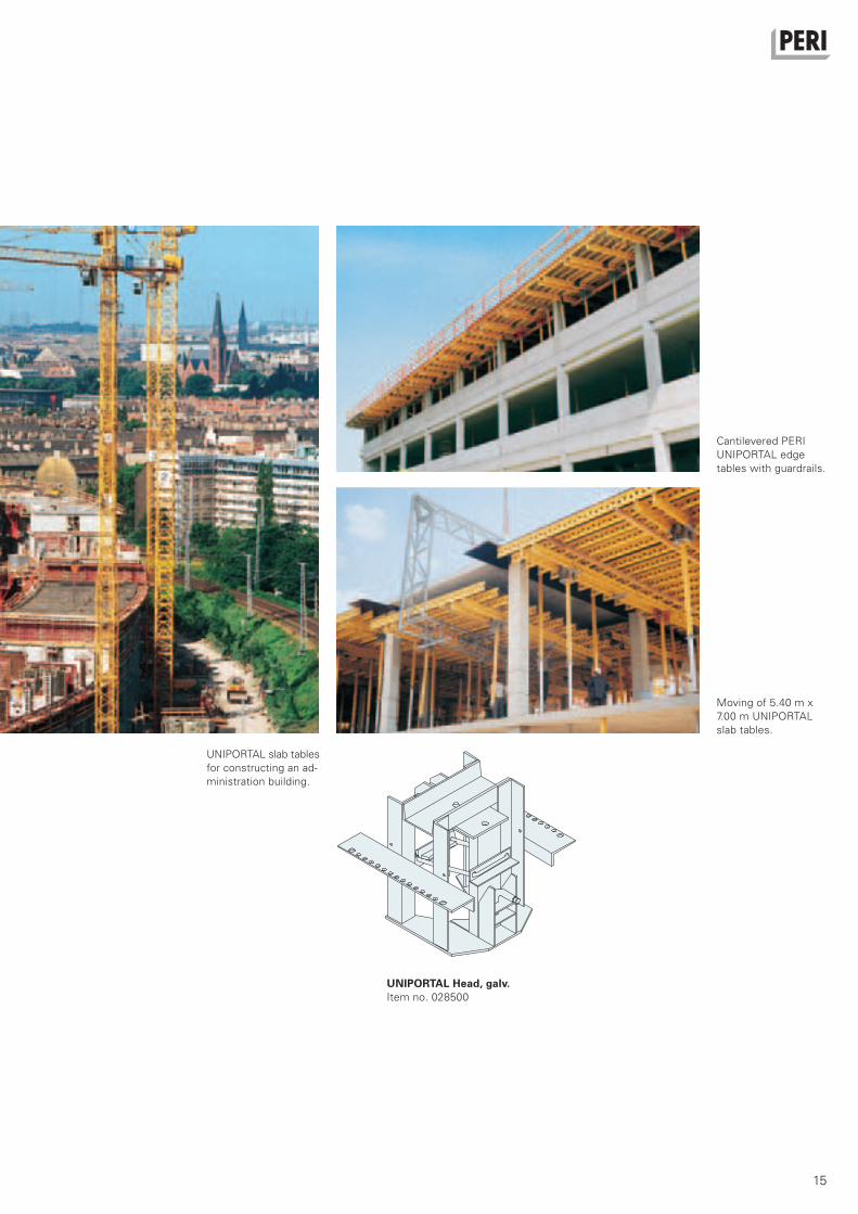
Cantilevered PERI
UNIPORTAL edge
tables with guardrails.
Moving of 5.40 m x
7.00 m UNIPORTAL
slab tables.
UNIPORTAL slab tables
for constructing an ad-
ministration building.
UNIPORTAL Head, galv.Item no. 028500
Deckentisch_PR_e.indb 15 20.12.2007 15:25:06 Uhr
16
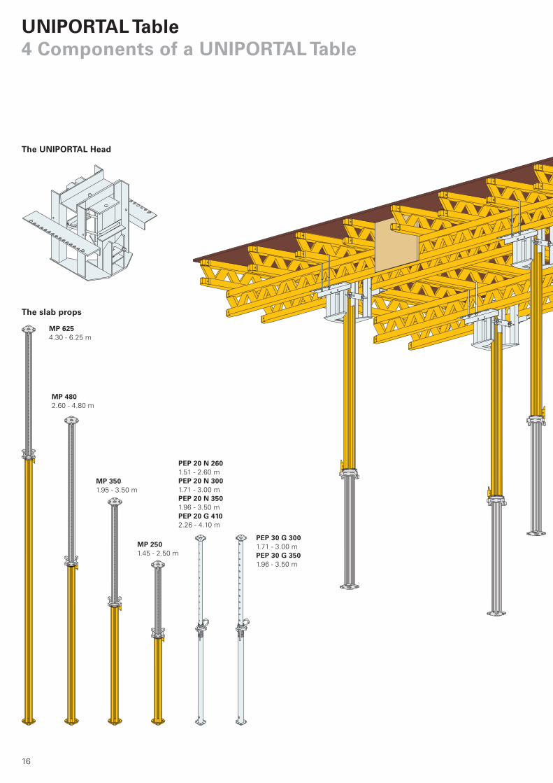
MP 2501.45 - 2.50 m
MP 3501.95 - 3.50 m
MP 4802.60 - 4.80 m
MP 6254.30 - 6.25 m
PEP 20 N 2601.51 - 2.60 m
PEP 20 N 3001.71 - 3.00 m
PEP 20 N 3501.96 - 3.50 m
PEP 20 G 4102.26 - 4.10 m
PEP 30 G 3001.71 - 3.00 m
PEP 30 G 3501.96 - 3.50 m
UNIPORTAL Table4 Components of a UNIPORTAL Table
The UNIPORTAL Head
The slab props
Deckentisch_PR_e.indb 16 20.12.2007 15:25:08 Uhr
17
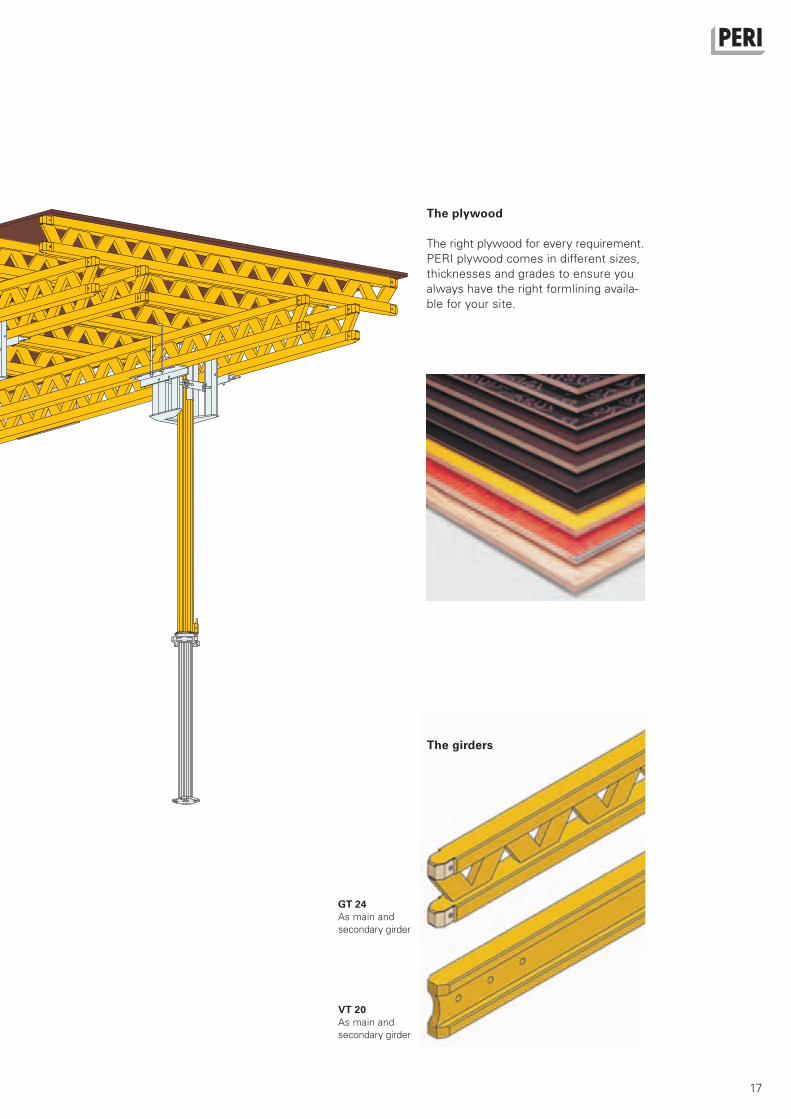
The plywood
The right plywood for every requirement.
PERI plywood comes in different sizes,
thicknesses and grades to ensure you
always have the right formlining availa-
ble for your site.
The girders
GT 24As main and
secondary girder
VT 20As main and
secondary girder
Deckentisch_PR_e.indb 17 20.12.2007 15:25:09 Uhr

18
UNIPORTAL TablePrinciple of operation of a UNIPORTAL Head
The PERI UNIPORTAL Head allows the props to be folded in one direction.This is particularly advantageous when
negotiating parapets or downstand
beams.
Locking pin
Locking device
Hinging mechanism
Connecting props
Slab props from ø 57 mm and PERI
MULTIPROPs can be clamped to the
outer or inner tube.
1. Use a board to lift the locking pin
while standing on the slab below, and
fold the prop.
2. Swing prop down again with hinging
mechanism. In so doing, the locking
pin is engaged in the locking device.
The UNIPORTAL clamping
device can easily be oper-
ated with just a hammer.
EN_Deckentisch_018-019.indd 18 08.01.2008 11:25:48 Uhr
19
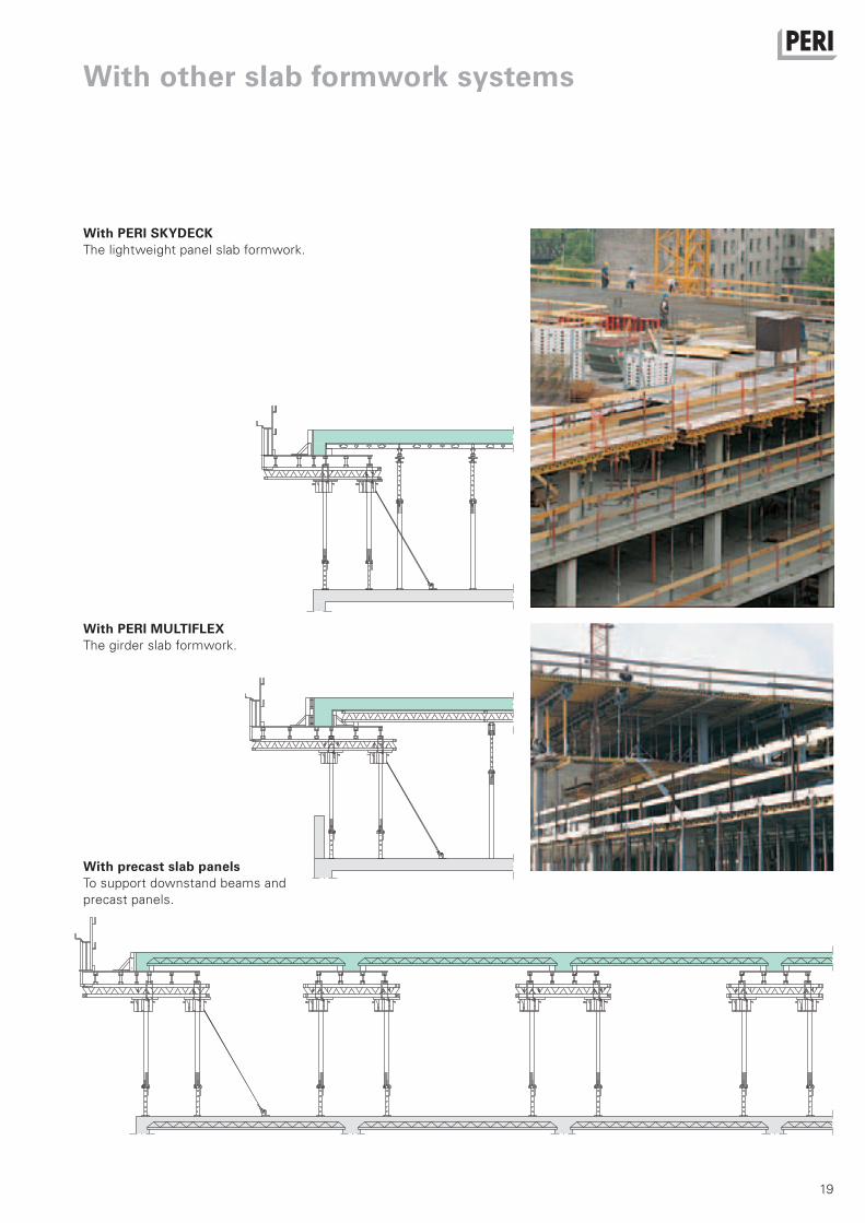
With other slab formwork systems
With PERI SKYDECKThe lightweight panel slab formwork.
With PERI MULTIFLEXThe girder slab formwork.
With precast slab panelsTo support downstand beams and
precast panels.
EN_Deckentisch_018-019.indd 19 08.01.2008 11:25:55 Uhr

20
1
5
2
6
UNIPORTAL TableAssembly sequence
A flat, level assembly platform is required. Prepare locating battens for
heads and girders as shown on assembly drawings.
Note: It is essential to point the UNIPORTAL heads in the direction required
for folding.
Lay main girders on UNIPORTAL heads, align and fix with C clamps.
Secure with M 8x60 lag screw, Item no. 024270, at each fixing point.
Now fix the nogging-piece to the two outside main girders. Cut piece of
scrap formlining to size and screw on. Lay sheets of plywood on and align.
Screw the plywood down with approx. 10 pieces 6 x 60 torx screws,
Item no. 024470. A marking gauge makes the work easier.
Deckentisch_PR_e.indb 20 20.12.2007 15:25:21 Uhr
21
3
7
4
8
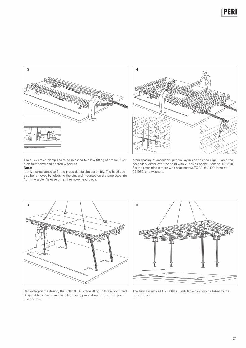
The quick-action clamp has to be released to allow fitting of props. Push
prop fully home and tighten wingnuts.
Note: It only makes sense to fit the props during site assembly. The head can
also be removed by releasing the pin, and mounted on the prop separate
from the table. Release pin and remove head piece.
Mark spacing of secondary girders, lay in position and align. Clamp the
secondary girder over the head with 2 tension hoops, Item no. 028550.
Fix the remaining girders with spax screws TX 30, 6 x 100, Item no.
024950, and washers.
Depending on the design, the UNIPORTAL crane lifting units are now fitted.
Suspend table from crane and lift. Swing props down into vertical posi-
tion and lock.
The fully assembled UNIPORTAL slab table can now be taken to the
point of use.
Deckentisch_PR_e.indb 21 20.12.2007 15:25:27 Uhr
22
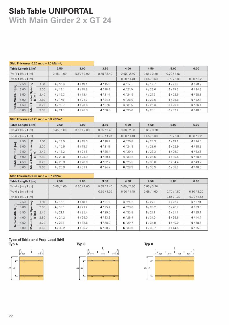
2.50 3.00 3.50 4.00 4.50 5.00 6.00
0.45 / 1.60 0.50 / 2.00 0.55 / 2.40 0.60 / 2.80 0.65 / 3.20 0.70 / 3.60
0.60 / 1.40 0.65 / 1.60 0.70 / 1.80 0.80 / 2.20
2.50 1.60 4 / 10.9 4 / 13.1 4 / 15.3 4 / 17.5 4 / 19.7 4 / 21.9 6 / 20.2
3.00 2.00 4 / 13.1 4 / 15.8 4 / 18.4 4 / 21.0 4 / 23.6 6 / 19.3 6 / 24.3
3.50 2.40 4 / 15.3 4 / 18.4 4 / 21.4 4 / 24.5 4 / 27.6 6 / 22.6 6 / 28.3
4.00 2.80 4 / 17.5 4 / 21.0 4 / 24.5 4 / 28.0 6 / 22.5 6 / 25.8 6 / 32.4
4.50 3.20 4 / 19.7 4 / 23.6 4 / 27.6 4 / 31.5 6 / 25.3 6 / 29.0 6 / 36.4
5.00 3.60 4 / 21.9 4 / 26.3 4 / 30.6 4 / 35.0 6 / 28.1 6 / 32.2 6 / 40.5
2.50 3.00 3.50 4.00 4.50 5.00 6.00
0.45 / 1.60 0.50 / 2.00 0.55 / 2.40 0.60 / 2.80 0.65 / 3.20
0.55 / 1.20 0.60 / 1.40 0.65 / 1.60 0.70 / 1.80 0.80 / 2.20
2.50 1.60 4 / 13.0 4 / 15.6 4 / 18.2 4 / 20.8 4 / 23.3 6 / 19.1 6 / 24.0
3.00 2.00 4 / 15.6 4 / 18.7 4 / 21.8 4 / 24.9 4 / 28.0 6 / 22.9 6 / 28.8
3.50 2.40 4 / 18.2 4 / 21.8 4 / 25.4 4 / 29.1 6 / 23.3 6 / 26.7 6 / 33.6
4.00 2.80 4 / 20.8 4 / 24.9 4 / 29.1 4 / 33.2 6 / 26.6 6 / 30.6 6 / 38.4
4.50 3.20 4 / 23.3 4 / 28.0 4 / 32.7 6 / 25.5 6 / 30.0 6 / 34.4 6 / 43.2
5.00 3.60 4 / 25.9 4 / 31.1 6 / 24.7 6 / 28.3 6 / 33.3 6 / 38.2 6 / 48.0
2.50 3.00 3.50 4.00 4.50 5.00 6.00
0.45 / 1.60 0.50 / 2.00 0.55 / 2.40 0.60 / 2.80 0.65 / 3.20
0.55 / 1.20 0.60 / 1.40 0.65 / 1.60 0.70 / 1.80 0.80 / 2.20
0.55 / 1.30 0.70 / 1.53
2.50 1.60 4 / 15.1 4 / 18.1 4 / 21.1 4 / 24.2 4 / 27.2 6 / 22.2 6 / 27.9
3.00 2.00 4 / 18.1 4 / 21.7 4 / 25.4 4 / 29.0 6 / 23.2 6 / 26.7 6 / 33.5
3.50 2.40 4 / 21.1 4 / 25.4 4 / 29.6 4 / 33.8 6 / 27.1 6 / 31.1 6 / 39.1
4.00 2.80 4 / 24.2 4 / 29.0 4 / 33.8 6 / 26.4 6 / 31.0 6 / 35.6 6 / 44.7
4.50 3.20 4 / 27.2 4 / 32.6 4 / 38.0 6 / 29.7 6 / 34.9 6 / 40.0 6 / 50.3
5.00 3.60 4 / 30.2 4 / 36.2 6 / 28.7 6 / 33.0 6 / 38.7 6 / 44.5 6 / 55.9
Slab Table UNIPORTALWith Main Girder 2 x GT 24
B
L
b
lc c
B
L
b
lc cl
B
L
b
lc cl l
Typ 6 Typ 8Typ 4Type of Table and Prop Load [kN]
Slab Thickness 0.20 m; q = 7.0 kN/m²;
Table Length L [m]
Typ 4 c [m] / l [m]
Typ 6 c [m] / l [m]
Tab
le W
idth
B [
m]
Mai
n G
ird
er S
pac
ing
b [
m]
Slab Thickness 0.25 m; q = 8.3 kN/m²;
Table Length L [m]
Typ 4 c [m] / l [m]
Typ 6 c [m] / l [m]
Tab
le W
idth
B [
m]
Mai
n G
ird
er S
pac
ing
b [
m]
Slab Thickness 0.30 m; q = 9.7 kN/m²;
Table Length L [m]
Typ 4 c [m] / l [m]
Typ 6 c [m] / l [m]
Typ 8 c [m] / l [m]
Tab
le W
idth
B [
m]
Mai
n G
ird
er S
pac
ing
b [
m]
Seite_22-25 22 21.12.2007 11:32:51 Uhr

23
2.50 3.00 3.50 4.00 4.50 5.00 6.00
0.45 / 1.60 0.50 / 2.00 0.55 / 2.40
0.55 / 1.20 0.60 / 1.40 0.65 / 1.60 0.70 / 1.80 0.80 / 2.20
0.70 / 1.53
2.50 1.60 4 / 17.5 4 / 21.0 4 / 24.5 4 / 28.1 6 / 22.5 6 / 25.8 6 / 32.4
3.00 2.00 4 / 21.0 4 / 25.2 4 / 29.5 4 / 33.7 6 / 27.0 6 / 31.0 6 / 38.9
3.50 2.40 4 / 24.5 4 / 29.5 4 / 34.4 4 / 39.3 6 / 31.5 6 / 36.2 6 / 45.4
4.00 2.80 4 / 28.1 4 / 33.7 4 / 39.3 6 / 30.6 6 / 36.0 6 / 41.3 6 / 51.9
4.50 3.20 4 / 31.6 4 / 37.9 6 / 30.0 6 / 34.4 6 / 40.5 6 / 46.5 6 / 38.0
5.00 3.60 4 / 35.1 4 / 42.1 6 / 33.4 6 / 38.3 6 / 45.0 6 / 51.7 8 / 42.2
2.50 3.00 3.50 4.00 4.50 5.00 6.00
0.45 / 1.60 0.50 / 2.00 0.55 / 2.40 0.60 / 2.80
0.45 / 1.05 0.55 / 1.20 0.60 / 1.40 0.65 / 1.60 0.70 / 1.80 0.80 / 2.20
0.55 / 1.30 0.70 / 1.53
2.50 1.60 4 / 20.0 4 / 24.0 4 / 28.0 4 / 32.0 6 / 25.6 6 / 29.4 6 / 37.0
3.00 2.00 4 / 24.0 4 / 28.8 4 / 33.5 6 / 26.2 6 / 30.7 6 / 35.3 6 / 44.4
3.50 2.40 4 / 28.0 4 / 33.5 4 / 39.1 6 / 30.5 6 / 35.9 6 / 41.2 6 / 51.7
4.00 2.80 4 / 32.0 4 / 38.3 6 / 30.4 6 / 34.9 6 / 41.0 6 / 47.1 8 / 38.5
4.50 3.20 4 / 35.9 6 / 29.6 6 / 34.2 6 / 39.2 6 / 46.1 6 / 53.0 8 / 43.3
5.00 3.60 4 / 39.9 6 / 32.9 6 / 38.0 6 / 43.6 6 / 51.2 8 / 41.2 8 / 48.1
2.50 3.00 3.50 4.00 4.50 5.00 6.00
0.45 / 1.60 0.50 / 2.00
0.40 / 0.85 0.45 / 1.05 0.55 / 1.20 0.60 / 1.40 0.65 / 1.60 0.70 / 1.80 0.80 / 2.20
0.45 / 1.03 0.50 / 1.17 0.55 / 1.30 0.70 / 1.53
0.55 / 1.23
2.50 1.60 4 / 24.8 4 / 29.8 4 / 34.8 6 / 27.1 6 / 31.9 6 / 36.6 6 / 46.0
3.00 2.00 4 / 29.8 4 / 35.8 6 / 28.4 6 / 32.5 6 / 38.3 6 / 43.9 6 / 55.2
3.50 2.40 4 / 34.8 4 / 41.7 6 / 33.1 6 / 38.0 6 / 44.6 6 / 51.2 8 / 41.9
4.00 2.80 4 / 39.8 6 / 32.7 6 / 37.8 6 / 43.4 6 / 51.0 8 / 41.0 8 / 47.9
4.50 3.20 6 / 30.8 6 / 36.8 6 / 42.6 6 / 48.8 8 / 41.3 8 / 46.2 10 / 44.5
5.00 3.60 6 / 34.2 6 / 40.9 6 / 47.3 8 / 40.5 8 / 45.9 8 / 51.3 10 / 49.4
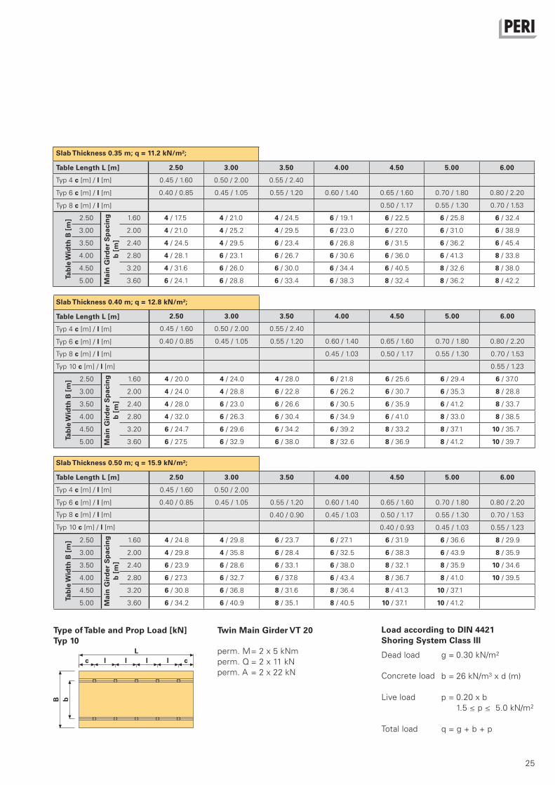
Type of Table and Prop Load [kN]
perm. M= 2 x 7 kNm
perm. Q = 2 x 14 kN
perm. A = 2 x 28 kN
B
L
b
lc cl l l
Typ 10
Slab Thickness 0.35 m; q = 11.2 kN/m²;
Table Length L [m]
Typ 4 c [m] / l [m]
Typ 6 c [m] / l [m]
Typ 8 c [m] / l [m]
Tab
le W
idth
B [
m]
Mai
n G
ird
er S
pac
ing
b [
m]
Slab Thickness 0.40 m; q = 12.8 kN/m²;
Table Length L [m]
Typ 4 c [m] / l [m]
Typ 6 c [m] / l [m]
Typ 8 c [m] / l [m]
Tab
le W
idth
B [
m]
Mai
n G
ird
er S
pac
ing
b [
m]
Slab Thickness 0.50 m; q = 15.9 kN/m²;
Table Length L [m]
Typ 4 c [m] / l [m]
Typ 6 c [m] / l [m]
Typ 8 c [m] / l [m]
Tab
le W
idth
B [
m]
Mai
n G
ird
er S
pac
ing
b [
m]
Typ 10 c [m] / l [m]
Twin Main Girder GT 24
g = 0.30 kN/m2
b = 26 kN/m3 x d (m)
p = 0.20 x b
1.5 ≤ p ≤ 5.0 kN/m2
q = g + b + p
Dead load
Load according to DIN 4421Shoring System Class III
Concrete load
Live load
Total load
Seite_22-25 23 21.12.2007 11:32:52 Uhr

24
2.50 3.00 3.50 4.00 4.50 5.00 6.00
0.45 / 1.60 0.50 / 2.00 0.55 / 2.40 0.60 / 2.80
0.55 / 1.20 0.60 / 1.40 0.65 / 1.60 0.70 / 1.80 0.80 / 2.20
0.55 / 1.30 0.70 / 1.53
2.50 1.60 4 / 15.1 4 / 18.1 4 / 21.1 4 / 24.2 6 / 19.4 6 / 22.2 6 / 27.9
3.00 2.00 4 / 18.1 4 / 21.7 4 / 25.4 6 / 19.8 6 / 23.2 6 / 26.7 6 / 33.5
3.50 2.40 4 / 21.1 4 / 25.4 4 / 29.6 6 / 23.1 6 / 27.1 6 / 31.1 6 / 39.1
4.00 2.80 4 / 24.2 4 / 29.0 6 / 23.0 6 / 26.4 6 / 31.0 6 / 35.6 8 / 29.1
4.50 3.20 4 / 27.2 4 / 32.6 6 / 25.9 6 / 29.7 6 / 34.9 6 / 40.0 8 / 32.7
5.00 3.60 4 / 30.2 4 / 36.2 6 / 28.7 6 / 33.0 6 / 38.7 8 / 31.2 8 / 36.3
2.50 3.00 3.50 4.00 4.50 5.00 6.00
0.45 / 1.60 0.50 / 2.00 0.55 / 2.40 0.60 / 2.80 0.65 / 3.20
0.60 / 1.40 0.65 / 1.60 0.70 / 1.80 0.80 / 2.20
2.50 1.60 4 / 10.9 4 / 13.1 4 / 15.3 4 / 17.5 4 / 19.7 6 / 16.1 6 / 20.2
3.00 2.00 4 / 13.1 4 / 15.8 4 / 18.4 4 / 21.0 6 / 16.8 6 / 19.3 6 / 24.3
3.50 2.40 4 / 15.3 4 / 18.4 4 / 21.4 4 / 24.5 6 / 19.6 6 / 22.6 6 / 28.3
4.00 2.80 4 / 17.5 4 / 21.0 4 / 24.5 6 / 19.1 6 / 22.5 6 / 25.8 6 / 32.4
4.50 3.20 4 / 19.7 4 / 23.6 4 / 27.6 6 / 21.5 6 / 25.3 6 / 29.0 6 / 36.4
5.00 3.60 4 / 21.9 4 / 26.3 4 / 30.6 6 / 23.9 6 / 28.1 6 / 32.2 6 / 40.5
2.50 3.00 3.50 4.00 4.50 5.00 6.00
0.45 / 1.60 0.50 / 2.00 0.55 / 2.40 0.60 / 2.80
0.55 / 1.20 0.60 / 1.40 0.65 / 1.60 0.70 / 1.80 0.80 / 2.20
0.70 / 1.53
2.50 1.60 4 / 13.0 4 / 15.6 4 / 18.2 4 / 20.8 6 / 16.6 6 / 19.1 6 / 24.0
3.00 2.00 4 / 15.6 4 / 18.7 4 / 21.8 4 / 24.9 6 / 20.0 6 / 22.9 6 / 28.8
3.50 2.40 4 / 18.2 4 / 21.8 4 / 25.4 6 / 19.8 6 / 23.3 6 / 26.7 6 / 33.6
4.00 2.80 4 / 20.8 4 / 24.9 4 / 29.1 6 / 22.6 6 / 26.6 6 / 30.6 6 / 38.4
4.50 3.20 4 / 23.3 4 / 28.0 6 / 22.2 6 / 25.5 6 / 30.0 6 / 34.4 6 / 43.2
5.00 3.60 4 / 25.9 4 / 31.1 6 / 24.7 6 / 28.3 6 / 33.3 6 / 38.2 8 / 31.2
Typ 6 Typ 8Typ 4Type of Table and Prop Load [kN]
Slab Table UNIPORTALWith Main Girder 2 x VT 20
B
L
b
lc c
B
L
b
lc cl
B
L
b
lc cl l
Slab Thickness 0.20 m; q = 7.0 kN/m²;
Table Length L [m]
Typ 4 c [m] / l [m]
Typ 6 c [m] / l [m]
Tab
le W
idth
B [
m]
Mai
n G
ird
er S
pac
ing
b [
m]
Slab Thickness 0.25 m; q = 8.3 kN/m²;
Table Length L [m]
Typ 4 c [m] / l [m]
Typ 6 c [m] / l [m]
Tab
le W
idth
B [
m]
Mai
n G
ird
er S
pac
ing
b [
m]
Typ 8 c [m] / l [m]
Slab Thickness 0.30 m; q = 9.7 kN/m²;
Table Length L [m]
Typ 4 c [m] / l [m]
Typ 6 c [m] / l [m]
Tab
le W
idth
B [
m]
Mai
n G
ird
er S
pac
ing
b [
m]
Typ 8 c [m] / l [m]
Seite_22-25 24 21.12.2007 11:32:53 Uhr
25
2.50 3.00 3.50 4.00 4.50 5.00 6.00
0.45 / 1.60 0.50 / 2.00 0.55 / 2.40
0.40 / 0.85 0.45 / 1.05 0.55 / 1.20 0.60 / 1.40 0.65 / 1.60 0.70 / 1.80 0.80 / 2.20
0.50 / 1.17 0.55 / 1.30 0.70 / 1.53
2.50 1.60 4 / 17.5 4 / 21.0 4 / 24.5 6 / 19.1 6 / 22.5 6 / 25.8 6 / 32.4
3.00 2.00 4 / 21.0 4 / 25.2 4 / 29.5 6 / 23.0 6 / 27.0 6 / 31.0 6 / 38.9
3.50 2.40 4 / 24.5 4 / 29.5 6 / 23.4 6 / 26.8 6 / 31.5 6 / 36.2 6 / 45.4
4.00 2.80 4 / 28.1 6 / 23.1 6 / 26.7 6 / 30.6 6 / 36.0 6 / 41.3 8 / 33.8
4.50 3.20 4 / 31.6 6 / 26.0 6 / 30.0 6 / 34.4 6 / 40.5 8 / 32.6 8 / 38.0
5.00 3.60 6 / 24.1 6 / 28.8 6 / 33.4 6 / 38.3 8 / 32.4 8 / 36.2 8 / 42.2
2.50 3.00 3.50 4.00 4.50 5.00 6.00
0.45 / 1.60 0.50 / 2.00 0.55 / 2.40
0.40 / 0.85 0.45 / 1.05 0.55 / 1.20 0.60 / 1.40 0.65 / 1.60 0.70 / 1.80 0.80 / 2.20
0.45 / 1.03 0.50 / 1.17 0.55 / 1.30 0.70 / 1.53
0.55 / 1.23
2.50 1.60 4 / 20.0 4 / 24.0 4 / 28.0 6 / 21.8 6 / 25.6 6 / 29.4 6 / 37.0
3.00 2.00 4 / 24.0 4 / 28.8 6 / 22.8 6 / 26.2 6 / 30.7 6 / 35.3 8 / 28.8
3.50 2.40 4 / 28.0 6 / 23.0 6 / 26.6 6 / 30.5 6 / 35.9 6 / 41.2 8 / 33.7
4.00 2.80 4 / 32.0 6 / 26.3 6 / 30.4 6 / 34.9 6 / 41.0 8 / 33.0 8 / 38.5
4.50 3.20 6 / 24.7 6 / 29.6 6 / 34.2 6 / 39.2 8 / 33.2 8 / 37.1 10 / 35.7
5.00 3.60 6 / 27.5 6 / 32.9 6 / 38.0 8 / 32.6 8 / 36.9 8 / 41.2 10 / 39.7
2.50 3.00 3.50 4.00 4.50 5.00 6.00
0.45 / 1.60 0.50 / 2.00
0.40 / 0.85 0.45 / 1.05 0.55 / 1.20 0.60 / 1.40 0.65 / 1.60 0.70 / 1.80 0.80 / 2.20
0.40 / 0.90 0.45 / 1.03 0.50 / 1.17 0.55 / 1.30 0.70 / 1.53
0.40 / 0.93 0.45 / 1.03 0.55 / 1.23
2.50 1.60 4 / 24.8 4 / 29.8 6 / 23.7 6 / 27.1 6 / 31.9 6 / 36.6 8 / 29.9
3.00 2.00 4 / 29.8 4 / 35.8 6 / 28.4 6 / 32.5 6 / 38.3 6 / 43.9 8 / 35.9
3.50 2.40 6 / 23.9 6 / 28.6 6 / 33.1 6 / 38.0 8 / 32.1 8 / 35.9 10 / 34.6
4.00 2.80 6 / 27.3 6 / 32.7 6 / 37.8 6 / 43.4 8 / 36.7 8 / 41.0 10 / 39.5
4.50 3.20 6 / 30.8 6 / 36.8 8 / 31.6 8 / 36.4 8 / 41.3 10 / 37.1
5.00 3.60 6 / 34.2 6 / 40.9 8 / 35.1 8 / 40.5 10 / 37.1 10 / 41.2
Type of Table and Prop Load [kN]
perm. M= 2 x 5 kNm
perm. Q = 2 x 11 kN
perm. A = 2 x 22 kN
Typ 10Twin Main Girder VT 20
g = 0.30 kN/m2
b = 26 kN/m3 x d (m)
p = 0.20 x b
1.5 ≤ p ≤ 5.0 kN/m2
q = g + b + p
Dead load
Load according to DIN 4421Shoring System Class III
Concrete load
Live load
Total load
B
L
b
lc cl l l
Slab Thickness 0.35 m; q = 11.2 kN/m²;
Table Length L [m]
Typ 4 c [m] / l [m]
Typ 6 c [m] / l [m]
Tab
le W
idth
B [
m]
Mai
n G
ird
er S
pac
ing
b [
m]
Typ 8 c [m] / l [m]
Slab Thickness 0.40 m; q = 12.8 kN/m²;
Table Length L [m]
Typ 4 c [m] / l [m]
Typ 6 c [m] / l [m]
Tab
le W
idth
B [
m]
Mai
n G
ird
er S
pac
ing
b [
m]
Typ 8 c [m] / l [m]
Typ 10 c [m] / l [m]
Slab Thickness 0.50 m; q = 15.9 kN/m²;
Table Length L [m]
Typ 4 c [m] / l [m]
Typ 6 c [m] / l [m]
Tab
le W
idth
B [
m]
Mai
n G
ird
er S
pac
ing
b [
m]
Typ 8 c [m] / l [m]
Typ 10 c [m] / l [m]
Seite_22-25 25 21.12.2007 11:32:54 Uhr
26
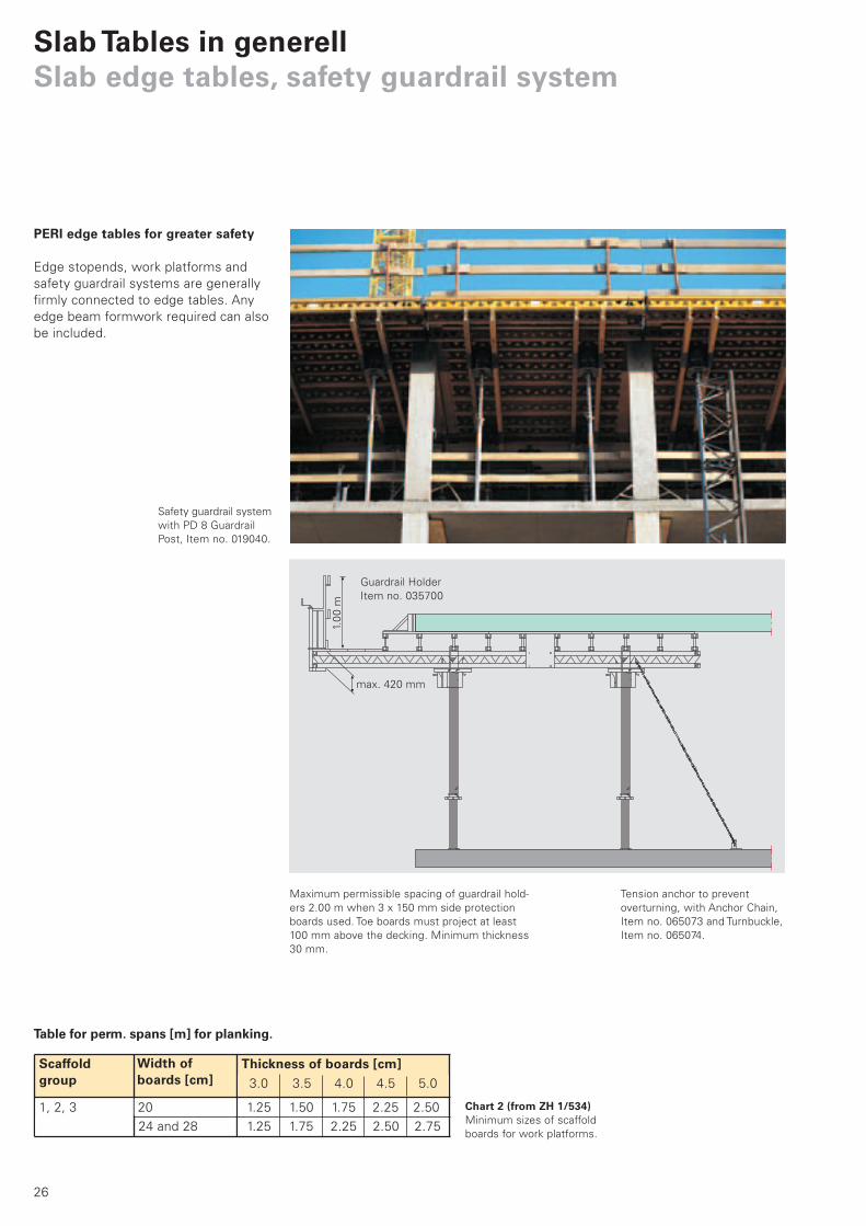
Tension anchor to prevent
overturning, with Anchor Chain,
Item no. 065073 and Turnbuckle,
Item no. 065074.
Table for perm. spans [m] for planking.
Maximum permissible spacing of guardrail hold-
ers 2.00 m when 3 x 150 mm side protection
boards used. Toe boards must project at least
100 mm above the decking. Minimum thickness
30 mm.
Guardrail Holder
Item no. 035700
max. 420 mm
Scaffold group
Width of boards [cm]
Thickness of boards [cm]
Safety guardrail system
with PD 8 Guardrail
Post, Item no. 019040.
24 and 28
PERI edge tables for greater safety
Edge stopends, work platforms and
safety guardrail systems are generally
firmly connected to edge tables. Any
edge beam formwork required can also
be included.
Slab Tables in generellSlab edge tables, safety guardrail system
1.0
0 m
3.0 3.5 4.0 4.5 5.0
1, 2, 3 20 1.25 1.50 1.75 2.25 2.50
1.25 1.75 2.25 2.50 2.75
Chart 2 (from ZH 1/534)Minimum sizes of scaffold
boards for work platforms.
Deckentisch_PR_e.indb 26 20.12.2007 15:25:29 Uhr

27
L
0.20 0.58 0.62 0.24 0.58
0.25 0.54 0.58 0.22 0.54
0.30 0.51 0.54 0.21 0.51
0.35 0.48 0.52 0.20 0.48
0.40 0.46 0.50 0.19 0.46
0.45 0.44 0.48 0.18 0.44
0.50 0.43 0.46 0.17 0.43
LL
Transverse infill
Suggested table configuration.
Longitudinal infill Chart of permissible spans L [m] for plywood
Initial planning should ensure ease of
striking after concreting. The infill area
can be used for temporary support.
Note:Concreting requires horizontal re-
straint all the way round, provided by
the formlining for example. The joint
must therefore be wedged or the ta-
bles connected by other means.
Edge girder
projection 40 mm
Note: The permissible deflection of a single span is L/300.
The infilling increases the loads on props of the slab tables.
Formwork Joint SSP
Item no. 030260
Striking play 20 mm
max. 20 mm
Slab thickness
h [m]
PERI Spruce 21 mm
Fin-Ply21 mm
3-S (cross) 21mm
PERI Beto 21 mm
50
mm
se
co
nd
ary
gir
de
r p
roje
cti
on
Striking play, Infilling
The fillers are located
at the column areas.
Deckentisch_PR_e.indb 27 20.12.2007 15:25:32 Uhr
28
Umsetzgabel 1 t / 5,0 mArt.-Nr. 101862
Betriebsanleitung
Umsetzgabel 1,75 t / 8,0 mArt.-Nr. 103212
Betriebsanleitung
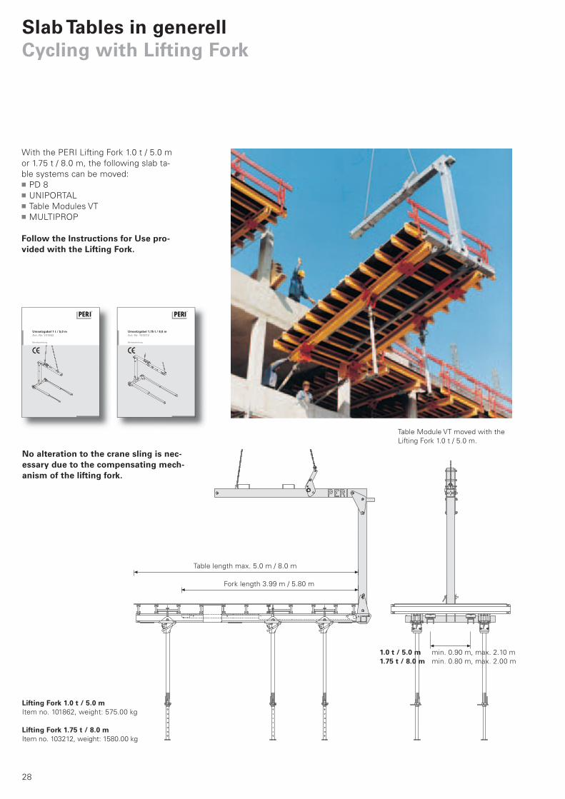
With the PERI Lifting Fork 1.0 t / 5.0 m
or 1.75 t / 8.0 m, the following slab ta-
ble systems can be moved:
PD 8
UNIPORTAL
Table Modules VT
MULTIPROP
Follow the Instructions for Use pro-vided with the Lifting Fork.
Table length max. 5.0 m / 8.0 m
Fork length 3.99 m / 5.80 m
No alteration to the crane sling is nec-essary due to the compensating mech-anism of the lifting fork.
Slab Tables in generellCycling with Lifting Fork
Lifting Fork 1.0 t / 5.0 mItem no. 101862, weight: 575.00 kg
Lifting Fork 1.75 t / 8.0 mItem no. 103212, weight: 1580.00 kg
1.0 t / 5.0 m min. 0.90 m, max. 2.10 m
1.75 t / 8.0 m min. 0.80 m, max. 2.00 m
Table Module VT moved with the
Lifting Fork 1.0 t / 5.0 m.
Deckentisch_PR_e.indb 28 20.12.2007 15:25:40 Uhr
29
1 2
3 4
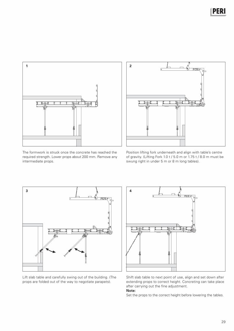
The formwork is struck once the concrete has reached the
required strength. Lower props about 200 mm. Remove any
intermediate props.
Position lifting fork underneath and align with table’s centre
of gravity. (Lifting Fork 1.0 t / 5.0 m or 1.75 t / 8.0 m must be
swung right in under 5 m or 8 m long tables).
Lift slab table and carefully swing out of the building. (The
props are folded out of the way to negotiate parapets).
Shift slab table to next point of use, align and set down after
extending props to correct height. Concreting can take place
after carrying out the fine adjustment.
Note:Set the props to the correct height before lowering the tables.
Deckentisch_PR_e.indb 29 20.12.2007 15:25:44 Uhr
30
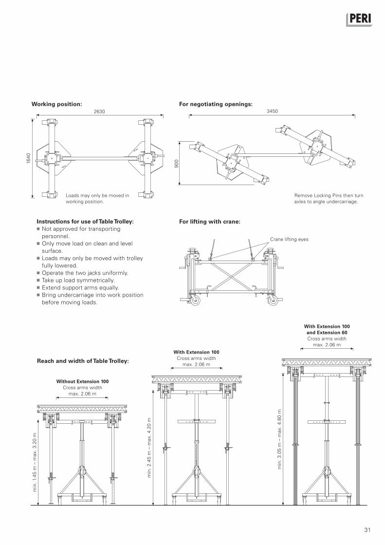
Slab Tables in generellMoving with Table Trolley
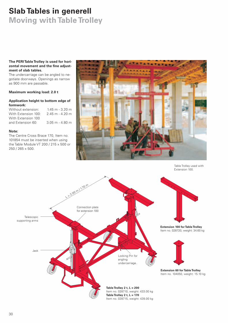
The PERI Table Trolley is used for hori-zontal movement and the fine adjust-ment of slab tables.The undercarriage can be angled to ne-
gotiate doorways. Openings as narrow
as 900 mm are passable.
Maximum working load: 2.0 t
Application height to bottom edge of formwork:Without extension: 1.45 m - 3.20 m
With Extension 100: 2.45 m - 4.20 m
With Extension 100
and Extension 60: 3.05 m - 4.80 m
Note:The Centre Cross Brace 170, Item no.
101854 must be inserted when using
the Table Module VT 200 / 215 x 500 or
250 / 265 x 500.
Telescopic
supporting arms
Jack
Connection plate
for extension 100
Locking Pin for
angling
undercarriage.
Extension 100 for Table TrolleyItem no. 028720, weight: 34.60 kg
Extension 60 for Table TrolleyItem no. 104050, weight: 15.10 kg
Table Trolley 2 t, L = 200Item no. 028710, weight: 433.00 kg
Table Trolley 2 t, L = 170Item no. 028715, weight: 428.00 kg
Table Trolley used with
Extension 100.
L = 2.00 m
/ 1.70 m
Deckentisch_PR_e.indb 30 20.12.2007 15:25:48 Uhr
31
2630
16
40
90
0
3450
Reach and width of Table Trolley:
min
. 1.
45
m –
max.
3.2
0 m
min
. 2
.45
m –
max.
4.2
0 m
min
. 3
.05
m –
max.
4.8
0 m
With Extension 100Cross arms width
max. 2.06 m
For lifting with crane:
Loads may only be moved in
working position.
Remove Locking Pins then turn
axles to angle undercarriage.
Instructions for use of Table Trolley:Not approved for transporting
personnel.
Only move load on clean and level
surface.
Loads may only be moved with trolley
fully lowered.
Operate the two jacks uniformly.
Take up load symmetrically.
Extend support arms equally.
Bring undercarriage into work position
before moving loads.
Working position: For negotiating openings:
Crane lifting eyes
Without Extension 100Cross arms width
max. 2.06 m
With Extension 100 and Extension 60Cross arms width
max. 2.06 m
Deckentisch_PR_e.indb 31 20.12.2007 15:25:49 Uhr

32
Slab Tables in generellMoving with Table Lift PTL 1250
With the PERI Table Lift PTL 1250, slab tables are quickly and easily moved horizontally.The electric drive function and the hy-
draulic lifting gear allows slab tables to
be moved without any effort.
The important adavantages of the PERI
Table Lift PTL 1250:
1-man operation feature saves on
manpower.
Flexible manoeuvring due to the 4-way
directional drive.
Simple changeover 0° - 90° to transver-
sal moving by means of control lever.
Safe moving of slab tables by means
of lift-dependent speed control.
Integrated crane lifting eyes for on-site
cross transportation.
Slab tables up to a weight of 1250 kg
can be safely moved.
The large reach and width of 1.57 m
up to 5.60 m allow the PERI Table
Lift PTL 1250 also to be used for
parking garages.
PERI Table Lift PTL 1250Item no. 108108,
weight: 1520.00 kg
max.
4.7
0 m
min
. 1.
57
m
min
. 2
.47
m
max.
5.6
0 m
Deckentisch_PR_e.indb 32 20.12.2007 15:25:53 Uhr
33
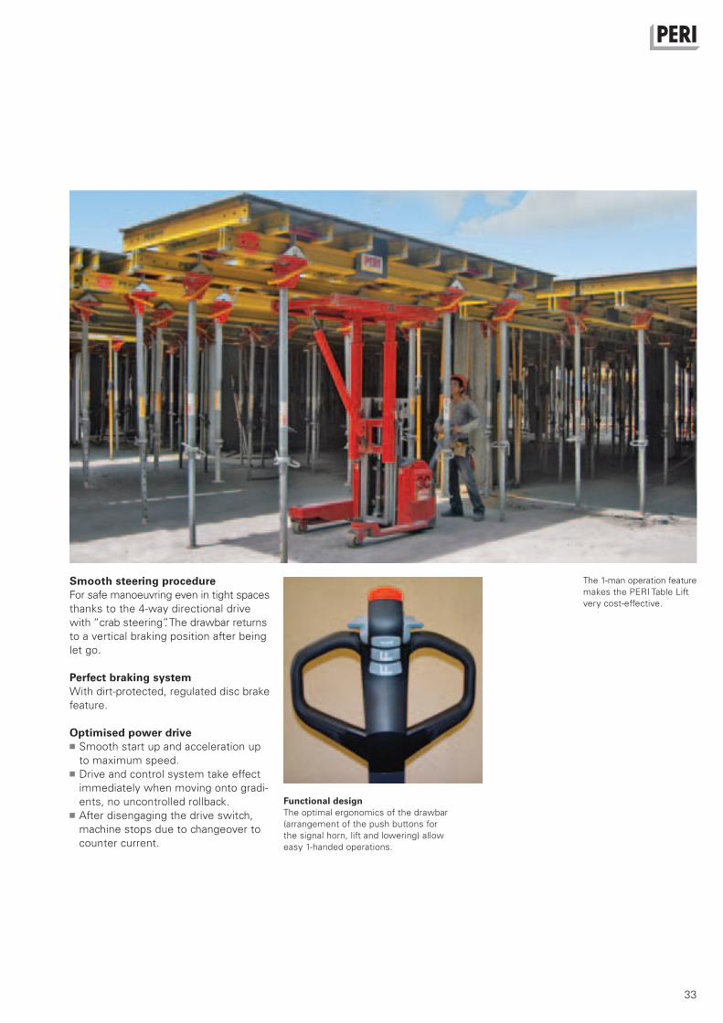
The 1-man operation feature
makes the PERI Table Lift
very cost-effective.
Functional designThe optimal ergonomics of the drawbar
(arrangement of the push buttons for
the signal horn, lift and lowering) allow
easy 1-handed operations.
Smooth steering procedureFor safe manoeuvring even in tight spaces
thanks to the 4-way directional drive
with “crab steering”. The drawbar returns
to a vertical braking position after being
let go.
Perfect braking systemWith dirt-protected, regulated disc brake
feature.
Optimised power driveSmooth start up and acceleration up
to maximum speed.
Drive and control system take effect
immediately when moving onto gradi-
ents, no uncontrolled rollback.
After disengaging the drive switch,
machine stops due to changeover to
counter current.
Deckentisch_PR_e.indb 33 20.12.2007 15:25:56 Uhr

34
PEP 20 N 260*L = 1.51 – 2.60 m
PEP 20 – 300PEP 20 N 300*L = 1.71 – 3.00 m
PEP 20 – 350PEP 20 N 350*L = 1.96 – 3.50 m
PEP 20 – 400PEP 20 G 410*L = 2.21 – 4.00 m
PEP 20 – 500
L = 2.71 – 5.00
1.60 35.0 35.0
1.70 35.0 35.0
1.80 35.0 35.0 35.0 35.0
1.90 35.0 35.0 35.0 35.0
2.00 33.5 35.0 35.0 35.0 35.0 35.0
2.10 31.9 35.0 32.2 35.0 35.0 35.0
2.20 30.9 35.0 30.5 35.0 35.0 35.0
2.30 29.8 35.0 29.0 35.0 35.0 35.0 35.0 35.0
2.40 28.6 35.0 27.8 35.0 35.0 35.0 35.0 35.0
2.50 27.1 32.9 26.9 35.0 35.0 35.0 35.0 35.0
2.60 24.8 29.4 26.1 35.0 33.8 35.0 35.0 35.0
2.70 24.9 31.7 32.4 35.0 35.0 35.0
2.80 23.3 28.5 31.2 35.0 35.0 35.0 35.0 35.0
2.90 21.6 25.7 30.2 35.0 35.0 35.0 35.0 35.0
3.00 20.0 23.2 29.2 35.0 35.0 35.0 35.0 35.0
3.10 27.5 34.6 33.6 35.0 35.0 35.0
3.20 25.7 31.5 32.5 35.0 35.0 35.0
3.30 24.1 28.8 31.2 35.0 35.0 35.0
3.40 22.4 26.4 29.6 35.0 35.0 35.0
3.50 20.7 24.1 27.8 33.9 35.0 35.0
3.60 26.1 31.2 35.0 35.0
3.70 24.5 28.9 35.0 35.0
3.80 23.0 26.8 35.0 35.0
3.90 21.6 24.8 35.0 35.0
4.00 20.1 22.8 34.2 35.0
4.10 32.3 35.0
4.20 30.6 35.0
4.30 28.9 34.0
4.40 27.4 31.9
4.50 26.0 29.9
4.60 24.6 28.1
4.70 23.4 26.4
4.80 22.1 24.9
4.90 20.9 23.4
5.00 20.0 21.8
Slab PropsPEP 20
Permissible Prop Load [kN] according to the Type Test
Exte
nsio
n
Le
ng
th [
m]
Outer TubeBottom
Inner TubeBottom
Outer TubeBottom
Inner Tube Bottom
Outer TubeBottom
Inner Tube Bottom
Outer TubeBottom
Inner Tube Bottom
Outer TubeBottom
Inner Tube Bottom
All PEP 20 Props conform with DIN EN
1065 class D with a permissible load for
the entire extension range of minimum
20 kN.
All PEP 20 Props clamped in the Table
Swivel Head or UNIPORTAL Head fitted
to PERI tableforms have a permissible
load of minimum 30 kN over the entire
extension range.
*For the N and G Props the application
Inner Tube at Bottom is only possible
with PERI Slab Tables or SKYDECK
(bolted head).
Seite_34-41 34 21.12.2007 11:34:01 Uhr

35
PEP 30 – 150
L = 0.96 – 1.50 m
PEP 30 – 250
L = 1.46 – 2.50 m
PEP 30 – 300PEP 30 G 300*L = 1.71 – 3.00 m
PEP 30 – 350PEP 30 G 350*L = 1.96 – 3.50 m
PEP 30 – 400
L = 2.21 – 4.00 m
1.00 35.0 35.0
1.10 35.0 35.0
1.20 35.0 35.0
1.30 34.9 35.0
1.40 34.2 35.0
1.50 33.5 35.0 40.0 40.0
1.60 40.0 40.0
1.70 40.0 40.0
1.80 40.0 40.0 40.0 40.0
1.90 38.5 40.0 40.0 40.0
2.00 36.8 40.0 40.0 40.0 40.0 40.0
2.10 35.3 40.0 40.0 40.0 40.0 40.0
2.20 34.4 40.0 40.0 40.0 40.0 40.0
2.30 33.3 40.0 40.0 40.0 40.0 40.0 40.0 40.0
2.40 32.1 37.6 40.0 40.0 40.0 40.0 40.0 40.0
2.50 30.1 34.8 39.9 40.0 40.0 40.0 40.0 40.0
2.60 38.8 40.0 40.0 40.0 40.0 40.0
2.70 37.4 40.0 40.0 40.0 40.0 40.0
2.80 35.8 40.0 40.0 40.0 40.0 40.0
2.90 33.2 37.2 40.0 40.0 40.0 40.0
3.00 30.4 33.8 40.0 40.0 40.0 40.0
3.10 40.0 40.0 40.0 40.0
3.20 37.6 40.0 40.0 40.0
3.30 35.0 37.6 40.0 40.0
3.40 32.3 34.6 40.0 40.0
3.50 30.0 31.6 40.0 40.0
3.60 40.0 40.0
3.70 40.0 40.0
3.80 37.4 40.0
3.90 34.8 37.0
4.00 32.2 33.9
PEP 30
Permissible Prop Load [kN] according to the Type Test
Exte
nsio
n
Le
ng
th [
m]
Outer TubeBottom
Inner Tube Bottom
Outer Tube Bottom
Inner Tube Bottom
Outer Tube Bottom
Inner Tube Bottom
Outer Tube Bottom
Inner Tube Bottom
Outer Tube Bottom
Inner Tube Bottom
All PEP 30 Props conform with DIN EN
1065 class E with a permissible load for
the entire extension range of minimum
30 kN.
All PEP 30 Props clamped in the Table
Swivel Head or UNIPORTAL Head fitted
to PERI tableforms have a permissible
load of minimum 40 kN (PEP 30-150 =
35 kN) over the entire extension range.
*For the N and G Props the application
Inner Tube at Bottom is only possible
with PERI Slab Tables or SKYDECK
(bolted head).
Seite_34-41 35 21.12.2007 11:34:02 Uhr

36
MP 250l = 1.45 – 2.50 m
MP 350l = 1.95 – 3.50 m
MP 480l = 2.60 – 4.80 m
MP 625l = 4.30 – 6.25 m
1.45 73.3 76.2
1.50 73.3 76.2
1.60 73.3 76.2
1.70 73.3 76.2
1.80 71.7 76.2
1.90 68.6 76.2
1.95 67.0 76.2 88.3 87.4
2.00 65.4 76.2 88.3 87.4
2.10 63.8 74.6 83.0 87.4
2.20 62.2 73.0 77.7 87.4
2.30 61.1 70.5 72.9 86.6
2.40 60.6 67.0 68.6 85.1
2.50 60.0 63.6 64.4 83.5
2.60 61.9 80.7 85.9 71.4
2.70 59.3 77.8 81.2 71.1
2.80 57.5 74.9 76.5 70.8
2.90 55.7 71.9 71.8 70.4
3.00 54.3 68.3 67.1 70.1
3.10 52.9 64.6 63.0 69.4
3.20 51.4 60.0 58.9 68.6
3.30 49.8 55.4 54.8 67.9
3.40 46.4 50.3 52.5 66.2
3.50 42.9 45.1 50.2 64.5
3.60 47.9 62.8
3.70 46.0 58.6
3.80 44.2 54.4
3.90 42.3 50.2
4.00 40.4 46.9
4.10 38.5 43.7
4.20 36.6 40.4
4.30 34.8 38.2 56.2 44.6
4.40 32.9 36.0 54.7 44.6
4.50 31.1 33.7 53.1 44.6
4.60 29.3 31.5 50.9 43.8
4.70 27.4 29.3 48.8 43.0
4.80 25.6 27.1 46.4 42.1
4.90 43.8 41.2
5.00 41.2 40.3
5.10 38.6 38.8
5.20 36.1 37.3
5.30 33.8 35.9
5.40 31.9 34.5
5.50 29.9 33.1
5.60 28.4 31.6
5.70 26.9 30.1
5.80 25.5 28.6
5.90 24.3 27.0
6.00 23.1 25.4
6.10 22.0 24.1
6.20 20.9 22.8
6.25 20.4 22.1
Slab PropsMULTIPROP 250, 350, 480, 625
Permissible Prop Load [kN] according to the Type Test
Extension
Length [m]
Outer Tube
Bottom
Inner Tube
Bottom
Outer Tube
Bottom
Inner Tube
Bottom
Outer Tube
Bottom
Inner Tube
Bottom
Outer Tube
Bottom
Inner Tube
Bottom
MULTIPROPs are classified according to offical approval as follows:MP 250 = Class T 25
MP 350 = Class R 35
MP 480 = Class D 45
MP 625 = Class D 60
Note:We recommend using the HD Wingnut Spanner, Item no. 022027, to release
the loads > 60 kN.
MULTIPROP 350 and 480 clamped in the Table Swivel Head or UNIPORTAL Head
fitted to PERI tableforms have a permissible load of minimum 56 kN for the
MP 350, and minimum of 36 kN for the MP 480 over the entire extension range.
Seite_34-41 36 21.12.2007 11:34:03 Uhr

37
Plywood 21 mm
L L L L L L L
f f
E =
30
00
N/m
m2
E =
40
00
N/m
m2
E =
50
00
N/m
m2
E =
60
00
N/m
m2
E =
70
00
N/m
m2
E =
80
00
N/m
m2
8.0 6.4 5.3 4.6 4.0
9.3 7.0 5.6 4.7 4.0 3.5
8.0 6.0 4.8 4.0 3.4 3.0
6.7 5.0 4.0 3.3 2.9 2.5
5.3 4.0 3.2 2.7 2.3 2.0
4.0 3.0 2.4 2.0 1.7 1.5
2.7 2.0 1.6 1.3 1.1 1.0
1.3 1.0 0.8 0.7 0.6 0.5
0.0 0.0 0.0 0.0 0.0 0.0De
fle
cti
on
f [
mm
]
0 10 20 30 40 50 60 70 80 90 100
0 20 40 60 80 100
10 30 50 70 90
Slab Thickness d [cm]
Fresh Concrete
Pressure q [kN/m²]
70
cm
60
cm
55
cm
50
cm
45
cm
35 cm
30 cm
25 cm
= 13 N/m
m2
= 11 N/m
m2
= 9 N/m
m2
= 7 N/m
m2
Span L
65
cm
= 5 N/m
m2
40 cm
75
cm
Wall Formwork
Slab Formwork
max. deflection
The E-Modulus and the permissible
stress are based on the grade and
moisture content of the plywood.
(See page “Overview, Static Values”)
0.0068 · q · L4
f = E · I
max. moment
(valid for min. 3 spans)
M = 0.1071 · q · L2
10.7
Seite_34-41 37 21.12.2007 11:34:03 Uhr

38
0.10 0.12 0.14 0.16 0.18 0.20
4.5 5.0 5.5 6.1 6.6 7.1
0.75 0.625 0.50 0.75 0.625 0.50 0.75 0.625 0.50 0.75 0.625 0.50 0.75 0.625 0.50 0.75 0.625 0.50
0.603.79 4.03 4.34 3.60 3.82 4.12 3.44 3.65 3.93 3.30 3.51 3.78 3.18 3.38 3.64 3.08 3.27 3.53
10.2 10.9 11.7 10.8 11.5 12.4 11.4 12.1 13.1 12.0 12.7 13.7 12.6 13.4 14.4 13.1 13.9 15.0
0.903.79 4.03 4.34 3.60 3.82 4.12 3.44 3.65 3.93 3.30 3.51 3.78 3.18 3.38 3.64 3.08 3.27 3.53
15.4 16.3 17.6 16.3 17.3 18.6 17.1 18.2 19.6 18.0 19.1 20.6 18.9 20.0 21.6 19.7 20.9 22.5
1.203.79 4.03 4.34 3.60 3.82 4.12 3.44 3.65 3.93 3.30 3.51 3.78 3.18 3.38 3.55 3.08 3.27 3.29
20.5 21.8 23.5 21.7 23.0 24.8 22.8 24.3 26.1 24.0 25.5 27.5 25.1 26.7 28.0 26.3 27.9 28.0
1.503.79 4.03 4.15 3.60 3.72 3.72 3.37 3.37 3.37 3.08 3.08 3.08 2.84 2.84 2.84 2.63 2.63 2.63
25.6 27.2 28.0 27.1 28.0 28.0 28.0 28.0 28.0 28.0 28.0 28.0 28.0 28.0 28.0 28.0 28.0 28.0
1.803.18 3.18 3.18 2.85 2.85 2.85 2.58 2.58 2.58 2.36 2.36 2.36 2.18 2.18 2.18 2.02 2.02 2.02
28.0 28.0 28.0 28.0 28.0 28.0 28.0 28.0 28.0 28.0 28.0 28.0 28.0 28.0 28.0 28.0 28.0 28.0
2.102.43 2.43 2.43 2.17 2.17 2.17 1.97 1.97 1.97 1.80 1.80 1.80 1.66 1.66 1.66 1.54 1.54 1.54
28.0 28.0 28.0 28.0 28.0 28.0 28.0 28.0 28.0 28.0 28.0 28.0 28.0 28.0 28.0 28.0 28.0 28.0
2.402.07 2.07 2.07 1.86 1.86 1.86 1.68 1.68 1.68 1.54 1.54 1.54 1.42 1.42 1.42 1.31 1.31 1.31
28.0 28.0 28.0 28.0 28.0 28.0 28.0 28.0 28.0 28.0 28.0 28.0 28.0 28.0 28.0 28.0 28.0 28.0
0.22 0.24 0.26 0.28 0.30 0.35
7.6 8.1 8.7 9.2 9.8 11.3
0.75 0.625 0.50 0.625 0.50 0.40 0.625 0.50 0.40 0.625 0.50 0.40 0.625 0.50 0.40 0.50 0.40
0.602.99 3.18 3.42 3.09 3.33 3.59 3.02 3.25 3.50 2.95 3.17 3.42 2.88 3.11 3.35 2.96 3.19
13.7 14.5 15.7 15.1 16.3 17.5 15.7 16.9 18.2 16.2 17.5 18.8 16.9 18.2 19.6 20.1 21.6
0.902.99 3.18 3.42 3.09 3.33 3.59 3.02 3.25 3.50 2.95 3.17 3.39 2.88 3.11 3.19 2.75 2.75
20.5 21.8 23.5 22.7 24.4 26.3 23.5 25.3 27.3 24.3 26.2 28.0 25.3 27.3 28.0 28.0 28.0
1.202.99 3.06 3.06 2.87 2.87 2.87 2.69 2.69 2.69 2.54 2.54 2.54 2.39 2.39 2.39 2.06 2.06
27.4 28.0 28.0 28.0 28.0 28.0 28.0 28.0 28.0 28.0 28.0 28.0 28.0 28.0 28.0 28.0 28.0
1.502.45 2.45 2.45 2.29 2.29 2.29 2.16 2.16 2.16 2.03 2.03 2.03 1.91 1.91 1.91 1.65 1.65
28.0 28.0 28.0 28.0 28.0 28.0 28.0 28.0 28.0 28.0 28.0 28.0 28.0 28.0 28.0 28.0 28.0
1.801.88 1.88 1.88 1.76 1.76 1.76 1.65 1.65 1.65 1.56 1.56 1.56 1.47 1.47 1.47 1.26 1.26
28.0 28.0 28.0 28.0 28.0 28.0 28.0 28.0 28.0 28.0 28.0 28.0 28.0 28.0 28.0 28.0 28.0
2.101.43 1.43 1.43 1.34 1.34 1.34 1.26 1.26 1.26 1.19 1.19 1.19 1.12 1.12 1.12 0.96 0.96
28.0 28.0 28.0 28.0 28.0 28.0 28.0 28.0 28.0 28.0 28.0 28.0 28.0 28.0 28.0 28.0 28.0
2.401.22 1.22 1.22 1.15 1.15 1.15 1.08 1.08 1.08 1.02 1.02 1.02 0.96 0.96 0.96 0.82 0.82
28.0 28.0 28.0 28.0 28.0 28.0 28.0 28.0 28.0 28.0 28.0 28.0 28.0 28.0 28.0 28.0 28.0
MULTIFLEXGT 24 used as Slab Girder
Pro
p S
pac
ing
c [
m]
Slab Thickness [m]
Load q* [kN/m²]
Sec. Girder Spacing a [m]
Pro
p S
pac
ing
c [
m]
Slab Thickness [m]
Load q* [kN/m²]
Sec. Girder Spacing a [m]
Seite_34-41 38 21.12.2007 11:34:05 Uhr

39
0.40 0.45 0.50 0.60 0.70 0.80 0.90 1.00
12.9 14.4 16.0 19.1 22.2 25.4 28.5 31.4
0.50 0.40 0.50 0.40 0.50 0.40 0.50 0.40 0.50 0.40 0.50 0.40 0.50 0.40 0.50 0.40
0.602.83 3.05 2.73 2.94 2.64 2.84 2.42 2.44 2.10 2.10 1.84 1.84 1.64 1.64 1.49 1.49
21.9 23.6 23.6 25.5 25.3 27.3 27.8 28.0 28.0 28.0 28.0 28.0 28.0 28.0 28.0 28.0
0.902.42 2.42 2.15 2.15 1.94 1.94 1.63 1.63 1.40 1.40 1.23 1.23 1.09 1.09 0.99 0.99
28.0 28.0 28.0 28.0 28.0 28.0 28.0 28.0 28.0 28.0 28.0 28.0 28.0 28.0 28.0 28.0
1.201.81 1.81 1.62 1.62 1.46 1.46 1.22 1.22 1.05 1.05 0.92 0.92 0.82 0.82 0.74 0.74
28.0 28.0 28.0 28.0 28.0 28.0 28.0 28.0 28.0 28.0 28.0 28.0 28.0 28.0 28.0 28.0
1.501.45 1.45 1.29 1.29 1.17 1.17 0.98 0.98 0.84 0.84 0.74 0.74 0.66 0.66 0.59 0.59
28.0 28.0 28.0 28.0 28.0 28.0 28.0 28.0 28.0 28.0 28.0 28.0 28.0 28.0 28.0 28.0
1.801.11 1.11 0.99 0.99 0.89 0.89 0.75 0.75 0.64 0.64 0.56 0.56 0.50 0.50 0.46 0.46
28.0 28.0 28.0 28.0 28.0 28.0 28.0 28.0 28.0 28.0 28.0 28.0 28.0 28.0 28.0 28.0
2.100.85 0.85 0.76 0.76 0.68 0.68 0.57 0.57 0.49 0.49 0.43 0.43 0.38 0.38 0.35 0.35
28.0 28.0 28.0 28.0 28.0 28.0 28.0 28.0 28.0 28.0 28.0 28.0 28.0 28.0 28.0 28.0
2.400.72 0.72 0.65 0.65 0.58 0.58 0.49 0.49 0.42 0.42 0.37 0.37 0.33 0.33 0.30 0.30
28.0 28.0 28.0 28.0 28.0 28.0 28.0 28.0 28.0 28.0 28.0 28.0 28.0 28.0 28.0 28.0
0.90 075100
1.20 075120
1.50 075150
1.80 075180
2.10 075210
2.40 075240
2.70 075270
3.00 075300
3.30 075330
3.60 075360
3.90 075390
4.20 075420
4.50 075450
4.80 075480
5.10 075510
5.40 075540
5.70 075570
6.00 075600
g = 0.40 kN/m2
b = 26 kN/m3 x d (m)
p = 0.20 x b
1.5 ≤ p ≤ 5.0 kN/m2
q = g + b + p
2.87
28.0
Dead load
*Load according to DIN 4421:
a
b
c
Main
gird
er spac
ing
Secondary girder spacing
Prop spacing
cc
b
a aa
Pro
p S
pac
ing
c [
m]
Slab Thickness [m]
Load q* [kN/m²]
Sec. Girder Spacing a [m]
Girder Lengths [m] Item no.
Table values mean the following:
perm. main girder spacing b [m]
actual prop load [kN]
The deflection has been limited to
l/500. Main girder support at centre of
girder node. Secondary girder assumed
as single span.
Concrete Load
Live load
Total load
Seite_34-41 39 21.12.2007 11:34:06 Uhr
40
0.10 0.12 0.14 0.16 0.18 0.20
4.5 5.0 5.5 6.1 6.6 7.1
0.75 0.625 0.50 0.75 0.625 0.50 0.75 0.625 0.50 0.75 0.625 0.50 0.75 0.625 0.50 0.75 0.625 0.50
0.603.10 3.30 3.55 2.94 3.13 3.37 2.81 2.99 3.22 2.70 2.87 3.09 2.60 2.77 2.98 2.52 2.68 2.89
8.4 8.9 9.6 8.9 9.4 10.1 9.3 9.9 10.7 9.8 10.4 11.2 10.3 10.9 11.8 10.7 11.4 12.3
0.903.10 3.30 3.55 2.94 3.13 3.37 2.81 2.99 3.22 2.70 2.87 3.09 2.60 2.77 2.98 2.52 2.68 2.89
12.6 13.4 14.4 13.3 14.1 15.2 14.0 14.9 16.0 14.7 15.6 16.9 15.4 16.4 17.7 16.1 17.1 18.4
1.203.10 3.30 3.55 2.94 3.13 3.37 2.81 2.99 3.22 2.70 2.87 3.03 2.60 2.77 2.79 2.52 2.58 2.58
16.8 17.8 19.2 17.7 18.8 20.3 18.7 19.9 21.4 19.6 20.9 20.6 21.8 22.0 21.5 22.0 22.0 22.0
1.503.10 3.26 3.26 2.92 2.92 2.92 2.65 2.65 2.65 2.42 2.42 2.42 2.23 2.23 2.23 2.07 2.07 2.07
21.0 22.0 22.0 22.0 22.0 22.0 22.0 22.0 22.0 22.0 22.0 22.0 22.0 22.0 22.0 22.0 22.0 22.0
1.802.50 2.50 2.50 2.24 2.24 2.24 2.03 2.03 2.03 1.86 1.86 1.86 1.71 1.71 1.71 1.59 1.59 1.59
22.0 22.0 22.0 22.0 22.0 22.0 22.0 22.0 22.0 22.0 22.0 22.0 22.0 22.0 22.0 22.0 22.0 22.0
2.101.91 1.91 1.91 1.71 1.71 1.71 1.55 1.55 1.55 1.42 1.42 1.42 1.30 1.30 1.30 1.21 1.21 1.21
22.0 22.0 22.0 22.0 22.0 22.0 22.0 22.0 22.0 22.0 22.0 22.0 22.0 22.0 22.0 22.0 22.0 22.0
2.401.54 1.54 1.54 1.38 1.38 1.38 1.25 1.25 1.25 1.15 1.15 1.15 1.06 1.06 1.06 0.98 0.98 0.98
22.0 22.0 22.0 22.0 22.0 22.0 22.0 22.0 22.0 22.0 22.0 22.0 22.0 22.0 22.0 22.0 22.0 22.0
0.22 0.24 0.26 0.28 0.30 0.35
7.6 8.1 8.7 9.2 9.8 11.3
0.75 0.625 0.50 0.625 0.50 0.40 0.625 0.50 0.40 0.625 0.50 0.40 0.625 0.50 0.40 0.50 0.40
0.602.45 2.60 2.80 2.53 2.73 2.94 2.47 2.66 2.86 2.41 2.60 2.80 2.36 2.54 2.74 2.42 2.61
11.2 11.9 12.8 12.4 13.3 14.3 12.8 13.8 14.9 13.3 14.3 15.4 13.8 14.9 16.0 16.4 17.7
0.902.45 2.60 2.80 2.53 2.73 2.94 2.47 2.66 2.82 2.41 2.60 2.66 2.36 2.50 2.50 2.16 2.16
16.8 17.8 19.2 18.5 20.0 21.5 19.2 20.7 22.0 19.9 21.5 22.0 20.7 22.0 22.0 22.0 22.0
1.202.41 2.41 2.41 2.25 2.25 2.25 2.12 2.12 2.12 2.00 2.00 2.00 1.88 1.88 1.88 1.62 1.62
22.0 22.0 22.0 22.0 22.0 22.0 22.0 22.0 22.0 22.0 22.0 22.0 22.0 22.0 22.0 22.0 22.0
1.501.92 1.92 1.92 1.80 1.80 1.80 1.69 1.69 1.69 1.60 1.60 1.60 1.50 1.50 1.59 1.30 1.30
22.0 22.0 22.0 22.0 22.0 22.0 22.0 22.0 22.0 22.0 22.0 22.0 22.0 22.0 22.0 22.0 22.0
1.801.48 1.48 1.48 1.38 1.38 1.38 1.30 1.30 1.30 1.23 1.23 1.23 1.15 1.15 1.15 1.00 1.00
22.0 22.0 22.0 22.0 22.0 22.0 22.0 22.0 22.0 22.0 22.0 22.0 22.0 22.0 22.0 22.0 22.0
2.101.13 1.13 1.13 1.05 1.05 1.05 0.99 0.99 0.99 0.93 0.93 0.93 0.88 0.88 0.88 0.76 0.76
22.0 22.0 22.0 22.0 22.0 22.0 22.0 22.0 22.0 22.0 22.0 22.0 22.0 22.0 22.0 22.0 22.0
2.400.91 0.91 0.91 0.85 0.85 0.85 0.80 0.80 0.80 0.76 0.76 0.76 0.71 0.71 0.71 0.61 0.61
22.0 22.0 22.0 22.0 22.0 22.0 22.0 22.0 22.0 22.0 22.0 22.0 22.0 22.0 22.0 22.0 22.0
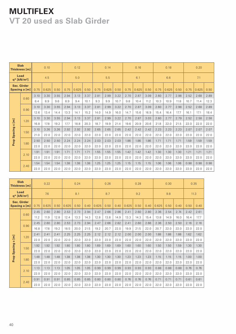
MULTIFLEXVT 20 used as Slab Girder
Pro
p S
pac
ing
c [
m]
Slab Thickness [m]
Load q* [kN/m2]
Sec. Girder Spacing a [m]
Pro
p S
pac
ing
c [
m]
Slab Thickness [m]
Load q* [kN/m²]
Sec. Girder Spacing a [m]
Seite_34-41 40 21.12.2007 11:34:07 Uhr

41
0.40 0.45 0.50
12.9 14.4 16.0
0.50 0.40 0.50 0.40 0.50 0.40
0.602.32 2.50 2.23 2.40 2.16 2.29
17.9 19.3 19.3 20.8 20.7 22.0
0.901.90 1.90 1.69 1.69 1.53 1.53
22.0 22.0 22.0 22.0 22.0 22.0
1.201.42 1.42 1.27 1.27 1.15 1.15
22.0 22.0 22.0 22.0 22.0 22.0
1.501.14 1.14 1.02 1.02 0.92 0.92
22.0 22.0 22.0 22.0 22.0 22.0
1.800.87 0.87 0.78 0.78 0.70 0.70
22.0 22.0 22.0 22.0 22.0 22.0
2.100.67 0.67 0.59 0.59 0.54 0.54
22.0 22.0 22.0 22.0 22.0 22.0
2.400.54 0.54 0.48 0.48 0.43 0.43
22.0 22.0 22.0 22.0 22.0 22.0
1.45 074990
2.15 074905
2.45 074910
2.65 074890
2.90 074920
3.30 074930
3.60 074940
3.90 074950
4.50 074960
4.90 074970
5.90 074980
a
b
cc
c
b
a aa
Pro
p S
pac
ing
c [
m]
Slab Thickness [m]
Load q* [kN/m²]
Sec. Girder Spacing a [m]
g = 0.40 kN/m2
b = 26 kN/m3 x d (m)
p = 0.20 x b
1.5 ≤ p ≤ 5.0 kN/m2
q = g + b + p
2.25
22.0
Dead load
*Load according to DIN 4421:
Main
gird
er spac
ing
Secondary girder spacing
Prop spacing
Girder Lengths [m] Item no.
Table values mean the following:
perm. main girder spacing b [m]
actual prop load [kN]
The deflection has been limited to
l/500. Secondary girder assumed as
single span.Concrete load
Live load
Total load
Seite_34-41 41 21.12.2007 11:34:08 Uhr
42
100
5060
520
ø 9
30
340
110
M 12
330
112
195
463
260
140
135
ø 20
125
135 215
500
540
340
150
ø 14
ø 20
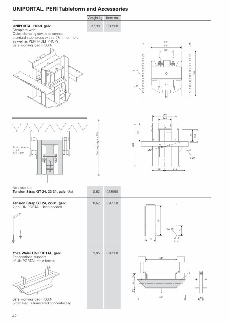
UNIPORTAL Head, galv. 37,90 028500Complete with:Quick clamping device to connectstandard steel props with ø 57mm or moreas well as PERI MULTIPROPs.Safe working load = 56kN
Accessories:Tension Strap GT 24, 22-31, galv. (2x) 0,62 028550
Tension Strap GT 24, 22-31, galv. 0,62 0285502 per UNIPORTAL Head needed.
Yoke Waler UNIPORTAL, galv. 9,85 028580For additional supportof UNIPORTAL table forms.
Safe working load = 56kNwhen load is transfered concentrically
Tension strap forGT 2422-31, galv.
Weight kg Item no.
SW 19
Sta
ckin
g he
ight
= 7
70
UNIPORTAL, PERI Tableform and Accessories

43
390
235
625
ø 9
ø 15
4706 x 50 = 300
256
80
400
370
397
244
150
256
260
353
270
278
140
180
500500
Table Swivel HeadConsisting of:Upper Part of Table Swivel Head 6,08 100955Middle Part of Table Swivel Head 9,06 100954Lower Part of Table Swivel Head 11,80 100956Load capacity: 56kN
Upper Part of Table Swivel Head 6,08 100955
Middle Part of Table Swivel Head 9,06 100954Complete with:mini wing nut Item no. 710338 (2x) andlocking washer Item no. 100960 (2x)
Lower Part of Table Swivel Head 11,80 100956Complete with:quick-action clamp for connecting allcommon tubular steel props from ø 57mmand PERI MULTIPROPs.
Spare part:mini wing nut 0,093 710338
Weight kg Item no.
VT 20K main girder GT 24 main girder

44
5000
2000
/250
0
750 2350 1150 750
2000
/250
0
4000
750 7502500
1500 325/575
430
75
325/575
75
2150/2650
2000/2500
VT Table ModulesPre-assembled tableforms available for hire.Formlining:finnish combi plywood 21mmComplete with:bottom part of table swivel headsupplied loose
VT Table Module VT 2,00/2,15x4,00m 396,0 072700VT Table Module VT 2,50/2,65x4,00m 451,0 072720VT Table Module VT 2,00/2,15x5,00m 503,0 072710VT Table Module VT 2,50/2,65x5,00m 569,0 072730
Stiffening Board, timber, 420x400mm 1,76 100778
Accessories:Lower Part of Table Swivel Head 11,80 100956
Weight kg Item no.
Longitudinal section
Longitudinal section
Cross section

45
15001640
125
50
270
2000 (1700)1610 (1310)
830
2630 (2330)
M 16x45
150
200
150
200
890
1270
105
ø 17
10
5
270
100
100
100100
200
150
600
100M16x45
100 100
Table Striking and Transportation 433,00 028710Trolley 2t, L = 200 Table Striking and Transportation 428,00 028715Trolley 2t, L = 170 For moving PERI tableforms.Not approved for transporting personnel.Only move on clean, level and sufficiently strong surface.Comply with relevant safety regulations.Minimum Height: 1,45m,Maximum Height: 3,20mwith extension 100: 4,20mwith extension 60 andextension 100: 4,80mObserve operating instructions!
Lifting appliance to BGV D8. Perm. load of each jack: 1t
Accessories:Centre Cross Bracing 200 26,30 102251Centre Cross Bracing 170 21,80 101854
Extension 60 15,10 1040502 extensions per trolleyWith the extensions 60 and 100 the workingheights of the transportation trolley areraised to a minimum height of 3,05m anda maximum height of 4,80m.Complete with:Hex. Bolt ISO 4017 M16x45-8.8, galv. andwith Hex. Nut ISO 7042 M16-8, galv. (4x)
Extension 100 for Table strikingand Transportation Trolley 34,60 0287202 extensions per trolley.Use trolley's telescopic arms.The Extension 100 increases thetrolley's working height:Min. height: 2,45m, max. height: 4,20mComplete with:Hex. Bolt ISO 4017 M16x45-8.8, galv. andwith Hex. Nut ISO 7042 M16-8, galv. (4x)
Weight kg Item no.
min
145
0
max
320
0
min 1460 - max 2060
46
1700
1921
1000
900
min
. 157
0m
ax. 5
m
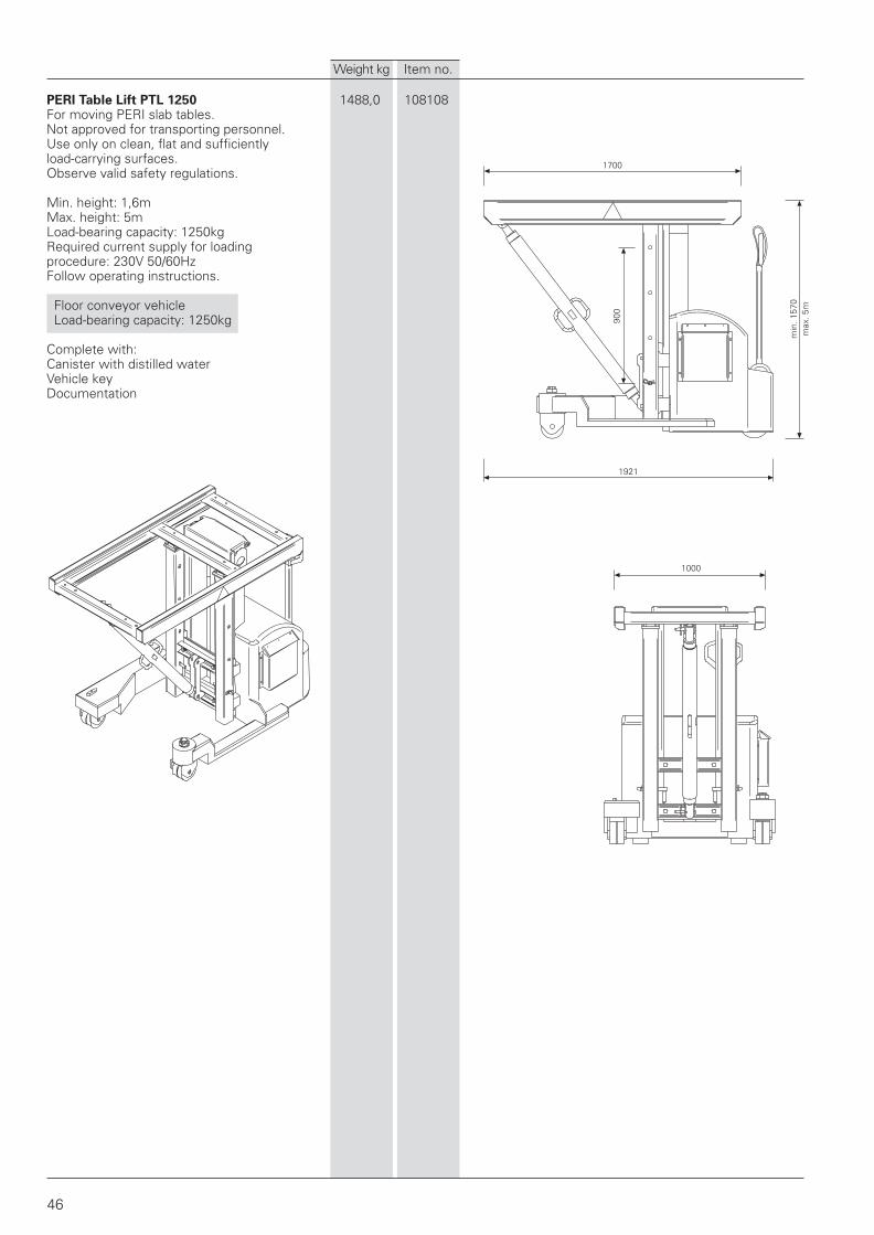
PERI Table Lift PTL 1250 1488,0 108108For moving PERI slab tables.Not approved for transporting personnel.Use only on clean, flat and sufficientlyload-carrying surfaces.Observe valid safety regulations.
Min. height: 1,6mMax. height: 5mLoad-bearing capacity: 1250kgRequired current supply for loadingprocedure: 230V 50/60HzFollow operating instructions.
Floor conveyor vehicle Load-bearing capacity: 1250kg
Complete with:Canister with distilled waterVehicle keyDocumentation
Weight kg Item no.
47
63
255
400
ø 50
ø 7
1800
900
3 x
150
4304
2161 750 750
3402
2598
720
2073
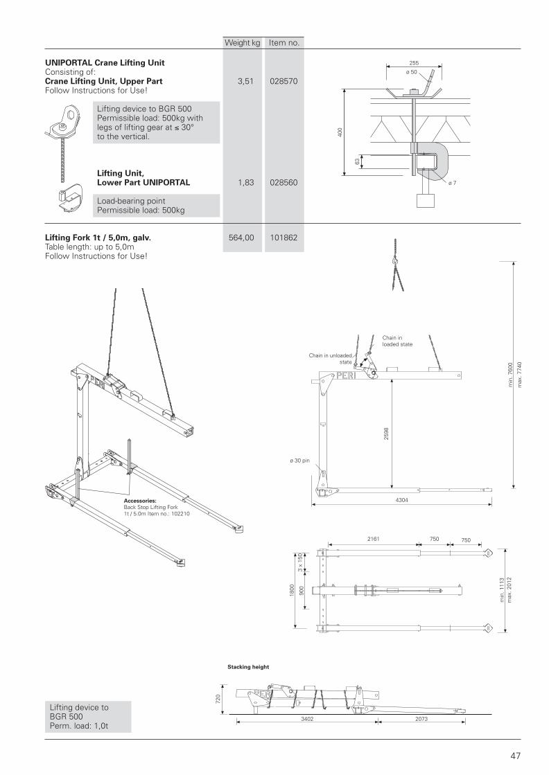
UNIPORTAL Crane Lifting Unit Consisting of:Crane Lifting Unit, Upper Part 3,51 028570Follow Instructions for Use!
Lifting device to BGR 500Permissible load: 500kg withlegs of lifting gear at 30°to the vertical.
Lifting Unit,Lower Part UNIPORTAL 1,83 028560
Load-bearing pointPermissible load: 500kg
Lifting Fork 1t / 5,0m, galv. 564,00 101862Table length: up to 5,0mFollow Instructions for Use!
Lifting device to BGR 500 Perm. load: 1,0t
Stacking height
ø 30 pin
Weight kg Item no.
Chain in unloadedstate
Chain inloaded state
Accessories:
Back Stop Lifting Fork1t / 5.0m Item no.: 102210
min
. 760
0
max
. 774
0
min
. 111
3m
ax. 2
012

800980
5050
2885 1240 1240
2000
800
600
6255
3030
48
900 74
2
123
123
50
M 20
Weight kg Item no.
Back Stop Lifting Fork 1t / 5,0m 8,61 102210Always use in pairs.
Lifting fork 1,75t / 8,0m, galv. 1552,00 103212Table length: up to 8,0mFollow Instructions for Use!
Lifting device to BGR 500 Perm. load: 1,75t
Chain in unloadedstate
Chain inloaded state
Stacking height
ø 40 pin
min
. 110
00
max
. 113
00
min
. 107
0m
ax. 2
270

49
1800
5645
4365
1800
790
1540 – 2100
3335
5720
22002340
4664
Hook 15kN, galv. 924,00 019130Table length 4,0 up to 7,0mFollow Instructions for Use!
Lifting device to BGR 500 Perm. load: 1,5t
Weight kg Item no.
Transit position
Bearers extendable
Manufacture of items shown on thispage has been discontinued. Theseitems are only available from rental stock.

190 65
50
70
185 35
995
460
120
112
44
15
ø 10
35
120
425
65
1750
1416
425
ø 5
45
32
ø 20 x 140FS 4/1
ø 21
82 45
115
352
395
Weight kg Item no.
max
420m
in 2
0
GT 24 main girder
VT 20K secondary girder
Handrail Holder GT 24/VT 20 5,67 101290For using the safety handrail post SGP.Complete with:pin 20x140 (1x) andcotter pin 4/1 (1x)For mounting onprimary girder: vertical SHS upwards;secondary girder: vertical SHS downwards;
Accessories:Handrail Post SGP 5,82 061260
Handrail Post SGP 5,82 061260For use with GT 24/VT 20 handrail holder.
Handrail Holder 9,79 035700For easy and quick clamping to concreteslabs for supporting handrails.Adjustable from 20 up to 420mm.

51
9181214
15101806
21022398
26942990
32863582
38784174
44704766
50625358
56545950
55
80
1
30
296 296
311
296163
240
120
6060
80
28
52
Weight kg Item no.
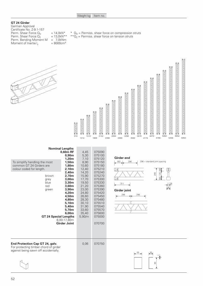
GT 24 GirderGerman ApprovalCertificate No. Z-9.1-157Perm. Shear Force QD = 14,0kN* * QD = Permiss. shear force on compression strutsPerm. Shear Force QZ = 13,0kN** **QZ = Permiss. shear force on tension strutsPerm. Bending Moment M = 7,0kNmMoment of Inertia ly = 8000cm4
Nominal Lengths0,60m RF 4,45 075090
0,90m 5,30 0751001,20m 7,10 075120
To simplify handling the most 1,50m 8,90 075150 common GT 24 Girders are 1,80m 10,60 075180 colour coded for length. 2,10m 12,40 075210
2,40m 14,20 075240 brown 2,70m 15,90 075270 grey 3,00m 17,70 075300 blue 3,30m 19,50 075330 red 3,60m 21,20 075360 green 3,90m 23,00 075390
4,20m 24,80 0754204,50m 26,60 0754504,80m 28,30 0754805,10m 30,10 0755105,40m 31,90 0755405,70m 33,60 0755706,00m 35,40 075600
GT 24 Special Lengths 5,90/m 0750006,00-17,80mGirder Joint 070700
End Protection Cap GT 24, galv. 0,06 070750For protecting timber chord of girderagainst being sawn off accidentally.
Girder joint
Girder end296 = standard joint spacing

53
4012
040
200
80
27
100 140 140
100
100ø 22
L
Weight kg Item no.
VT 20 GirderGerman ApprovalCertificate No. Z-9.1-216
perm. Q = 11,0kNperm. M = 5,0kNm ly = 4290cm4
L1,45m 8,60 0749902,15m 12,70 0749052,45m 14,50 0749102,65m 15,60 0748902,90m 17,10 0749203,30m 19,50 0749303,60m 21,20 0749403,90m 23,00 0749504,50m 26,70 0749604,90m 28,90 0749705,90m 34,80 074980
Cutting Cost VT Girder 074900
87
15012080
64
150
120
80
10 7564
BA
75
10
64
ø 40
ø 14
100
150
ø12,5
ø42
80 200
500
ø 89
ø 17
ø 17
54
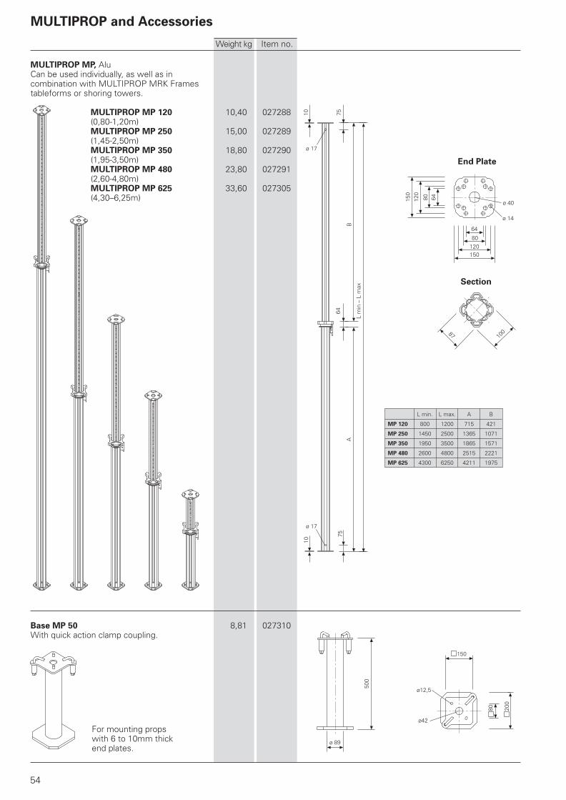
MULTIPROP and Accessories
MULTIPROP MP, AluCan be used individually, as well as incombination with MULTIPROP MRK Framestableforms or shoring towers.
MULTIPROP MP 120 10,40 027288(0,80-1,20m)MULTIPROP MP 250 15,00 027289(1,45-2,50m)MULTIPROP MP 350 18,80 027290(1,95-3,50m)MULTIPROP MP 480 23,80 027291(2,60-4,80m)MULTIPROP MP 625 33,60 027305(4,30–6,25m)
Base MP 50 8,81 027310With quick action clamp coupling.
For mounting propswith 6 to 10mm thickend plates.
Weight kg Item no.
L min. L max. A B
MP 120 800 1200 715 421
MP 250 1450 2500 1365 1071
MP 350 1950 3500 1865 1571
MP 480 2600 4800 2515 2221
MP 625 4300 6250 4211 1975
Section
End Plate
L m
in –
L m
ax
55
B
100
8B
AD1
6
8410
0
D2
L
ø 14
ø 9
40
100
80
120
A
L
D2
D1
ø 14
ø 9
40
100
80
120
82
Weight kg Item no.
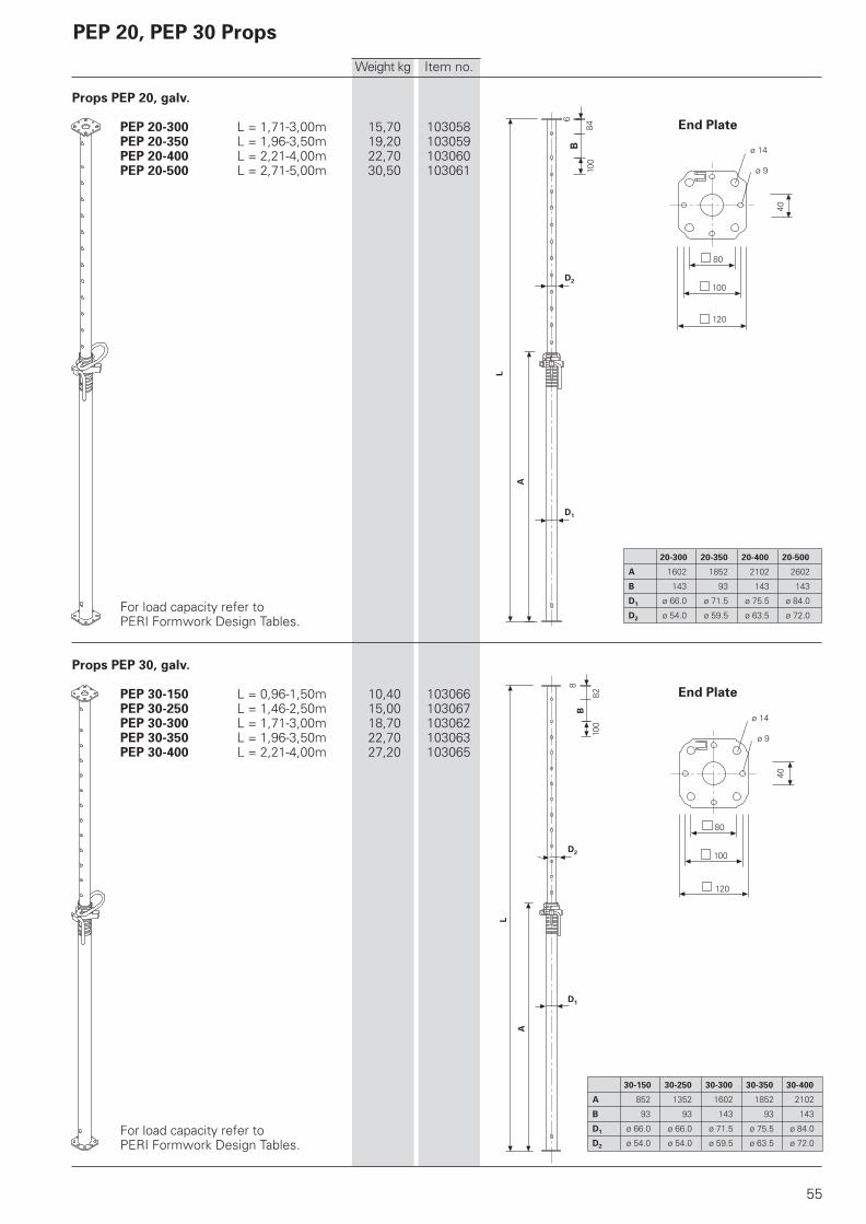
Props PEP 20, galv.
PEP 20-300 L = 1,71-3,00m 15,70 103058PEP 20-350 L = 1,96-3,50m 19,20 103059PEP 20-400 L = 2,21-4,00m 22,70 103060PEP 20-500 L = 2,71-5,00m 30,50 103061
For load capacity refer toPERI Formwork Design Tables.
Props PEP 30, galv.
PEP 30-150 L = 0,96-1,50m 10,40 103066PEP 30-250 L = 1,46-2,50m 15,00 103067PEP 30-300 L = 1,71-3,00m 18,70 103062PEP 30-350 L = 1,96-3,50m 22,70 103063PEP 30-400 L = 2,21-4,00m 27,20 103065
For load capacity refer toPERI Formwork Design Tables.
End Plate
20-300 20-350 20-400 20-500
A 1602 1852 2102 2602
B 143 93 143 143
D1 ø 66.0 ø 71.5 ø 75.5 ø 84.0
D2 ø 54.0 ø 59.5 ø 63.5 ø 72.0
End Plate
30-150 30-250 30-300 30-350 30-400
A 852 1352 1602 1852 2102
B 93 93 143 93 143
D1 ø 66.0 ø 66.0 ø 71.5 ø 75.5 ø 84.0
D2 ø 54.0 ø 54.0 ø 59.5 ø 63.5 ø 72.0
PEP 20, PEP 30 Props
56
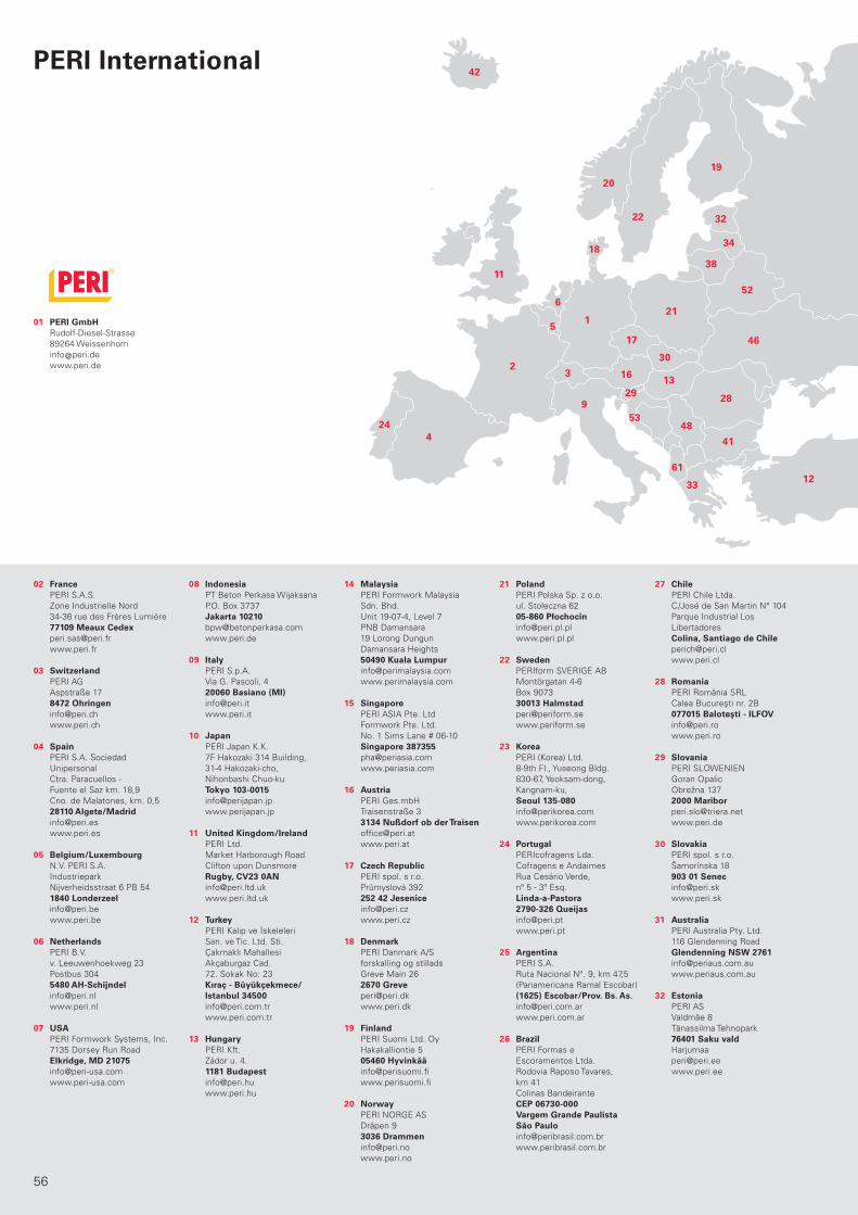
02 PERI S.A.S.
Zone Industrielle Nord
34-36 rue des Frères Lumière
77109 Meaux Cedex [email protected]
www.peri.fr
03 PERI AG
Aspstraße 17
8472 Ohringen [email protected]
www.peri.ch
04 PERI S.A. Sociedad
Unipersonal
Ctra. Paracuellos -
Fuente el Saz km. 18,9
Cno. de Malatones, km. 0,5
28110 Algete/Madrid [email protected]
www.peri.es
05 N.V. PERI S.A.
Industriepark
Nijverheidsstraat 6 PB 54
1840 Londerzeel [email protected]
www.peri.be
06 PERI B.V.
v. Leeuwenhoekweg 23
Postbus 304
5480 AH-Schijndel [email protected]
www.peri.nl
07 PERI Formwork Systems, Inc.
7135 Dorsey Run Road
Elkridge, MD 21075 [email protected]
www.peri-usa.com
08 PT Beton Perkasa Wijaksana
P.O. Box 3737
Jakarta 10210 [email protected]
www.peri.de
09 PERI S.p.A.
Via G. Pascoli, 4
20060 Basiano (MI) [email protected]
www.peri.it
10 PERI Japan K.K.
7F Hakozaki 314 Building,
31-4 Hakozaki-cho,
Nihonbashi Chuo-ku
Tokyo 103-0015 [email protected]
www.perijapan.jp
11 PERI Ltd.
Market Harborough Road
Clifton upon Dunsmore
Rugby, CV23 0AN [email protected]
www.peri.ltd.uk
12 PERI Kalıp ve İskeleleri
San. ve Tic. Ltd. Sti.
Çakmaklı Mahallesi
Akçaburgaz Cad.
72. Sokak No: 23
Kıraç - Büyükçekmece/ Istanbul 34500 [email protected]
www.peri.com.tr
13 PERI Kft.
Zádor u. 4.
1181 Budapest [email protected]
www.peri.hu
14 PERI Formwork Malaysia
Sdn. Bhd.
Unit 19-07-4, Level 7
PNB Damansara
19 Lorong Dungun
Damansara Heights
50490 Kuala Lumpur [email protected]
www.perimalaysia.com
15 PERI ASIA Pte. Ltd
Formwork Pte. Ltd.
No. 1 Sims Lane # 06-10
Singapore 387355 [email protected]
www.periasia.com
16 PERI Ges.mbH
Traisenstraße 3
3134 Nußdorf ob der Traisen [email protected]
www.peri.at
17 PERI spol. s r.o.
Průmyslová 392
252 42 Jesenice [email protected]
www.peri.cz
18 PERI Danmark A/S
forskalling og stillads
Greve Main 26
2670 Greve [email protected]
www.peri.dk
19 PERI Suomi Ltd. Oy
Hakakalliontie 5
05460 Hyvinkää [email protected]
www.perisuomi.fi
20 PERI NORGE AS
Dråpen 9
3036 Drammen [email protected]
www.peri.no
21 PERI Polska Sp. z o.o.
ul. Stołeczna 62
05-860 Płochocin [email protected]
www.peri.pl.pl
22 PERIform SVERIGE AB
Montörgatan 4-6
Box 9073
30013 Halmstad [email protected]
www.periform.se
23 PERI (Korea) Ltd.
8-9th Fl., Yuseong Bldg.
830-67, Yeoksam-dong,
Kangnam-ku,
Seoul 135-080 [email protected]
www.perikorea.com
24 PERIcofragens Lda.
Cofragens e Andaimes
Rua Cesário Verde,
nº 5 - 3º Esq.
Linda-a-Pastora 2790-326 Queijas [email protected]
www.peri.pt
25 PERI S.A.
Ruta Nacional N°. 9, km 47,5
(Panamericana Ramal Escobar)
(1625) Escobar/Prov. Bs. As. [email protected]
www.peri.com.ar
26 PERI Formas e
Escoramentos Ltda.
Rodovia Raposo Tavares,
km 41
Colinas Bandeirante
CEP 06730-000 Vargem Grande Paulista São Paulo [email protected]
www.peribrasil.com.br
27 PERI Chile Ltda.
C/José de San Martin N° 104
Parque Industrial Los
Libertadores
Colina, Santiago de Chile [email protected]
www.peri.cl
28 PERI România SRL
Calea Bucureşti nr. 2B
077015 Baloteşti - ILFOV [email protected]
www.peri.ro
29 PERI SLOWENIEN
Goran Opalic
Obrežna 137
2000 Maribor [email protected]
www.peri.de
30 PERI spol. s r.o.
Šamorínska 18
903 01 Senec [email protected]
www.peri.sk
31 PERI Australia Pty. Ltd.
116 Glendenning Road
Glendenning NSW 2761 [email protected]
www.periaus.com.au
32 PERI AS
Valdmäe 8
Tänassilma Tehnopark
76401 Saku vald Harjumaa
www.peri.ee
2
1
3
4
5
6
9
11
12
1316
17
18
19
20
22
21
24
2829
30
32
33
34
38
41
42
46
48
52
53
61
01 PERI GmbH Rudolf-Diesel-Strasse
89264 Weissenhorn
www.peri.de
France
Switzerland
Spain
Belgium/Luxembourg
Netherlands
USA
Indonesia
Italy
Japan
United Kingdom/Ireland
Turkey
Hungary
Malaysia
Singapore
Austria
Czech Republic
Denmark
Finland
Norway
Poland
Sweden
Korea
Portugal
Argentina
Brazil
Chile
Romania
Slovania
Slovakia
Australia
Estonia
PERI International
PERI_International.indd 56 18.08.2008 16:07:42 Uhr

57
33 PERI Hellas Ltd.
Sokratous Str.
5th kil. Koropi-Varis Ave.
P. O. Box 407
194 00 Koropi [email protected]
www.perihellas.gr
34 PERI SIA
Granita 26
1057 Riga [email protected]
www.peri-latvija.lv
35 PERI (L.L.C.)
Brashy Building,
Office No. 212
Shk. Zayed Road
P.O. Box 27933
Dubai [email protected]
www.perime.com
36 PERI Formwork Systems, Inc.
45 Nixon Road
Bolton, Ontario L7E 1K1 [email protected]
www.peri.ca
37 PERI GmbH
Lebanon Representative
Office
AYA Commercial Center,
7th floor,
Dora Highway,
Beirut P.O. Box 90 416 Jdeidet
www.peri.de
38 PERI UAB
Titnago st. 19
02300 Vilnius [email protected]
www.peri.lt
39 PERI S.A.
Route de Rabat, km. 5
Piste de Beni Touzine
Tanger [email protected]
www.peri.de
40 PERI Formwork
Engineering Ltd
16 Moshe Dayan st.,
P.O. Box 10202
Petach Tikva,
49002 Israel [email protected]
www.peri.co.il
41 PERI BULGARIA EOOD
Kv. Vragdebna
m. Nova Machala Nr. 46
1839 – Sofia [email protected]
www.peri.bg
42 MEST ltd.,
Fornubudum 5
220 Hafnarfjordur [email protected]
www.mest.is
43 TOO PERI Kazakhstan
Rubenstein Street 10
(Corner Dostyk Str. 7)
050010 Almaty [email protected]
www.peri.kz
44 OOO PERI
8 Etage, OOO PERI Buro
Krasnaya Presnya Str. 24
123022 Moskau [email protected]
www.peri.ru
45 PERI Wiehahn (Pty.) Ltd.
P.O. Box 2668
Bellville 7535 [email protected]
www.periwiehahn.co.za
46 TOW PERI Ukraina
23, M. Raskowa Str., B. 822
02002 Kiew [email protected]
www.peri.ua
47 PERI GmbH
Egypt Branch Office
24 A, Obour Gardens,
4th Floor, apt. # 1
Salah Salem Street
11361 Heliopolis Cairo [email protected]
www.peri.com.eg
48 PERI Oplate d.o.o.
Jurija Gagarina 81
11070 Novi Beograd [email protected]
www.peri.co.yu
49 PERI Cimbras y Andamios,
S.A. de C.V.
Parque de las Américas
KM 3.5 Carretera
Jorobas – Tula
Huehuetoca
Estado de México, C.P. 54680 [email protected]
www.peri.com.mx
50 PERI Kalıp ve İskeleleri
Baku Branch Office
28 May Küç. Ev 72 Menzil 27
Baku [email protected]
www.peri.com.tr
51 PERI Kalıp ve İskeleleri
Aşgabat Branch Office
Göroglu Sokak No. 130, Kat 2
744035 Aşgabat [email protected]
www.peri.com.tr
52 PERI Belarus
Pr. Nesawisimosti 11
Kopus-2 Zimmer: 526,528
220030 Minsk [email protected]
www.peri.com.tr
53 PERI oplate i skele d.o.o.
Dolenica 20
10 250 Donji Stupnik/ Zagreb [email protected]
www.peri.com.hr
54 PERI GmbH
Iran Branch Office
Flat 27, 5th floor, KAVE BLVD,
Building No. 246
P.O. Box 1939793669
Teheran-Iran [email protected]
www.peri.ir
55 PERI (India) Pvt Ltd
717 Palm Springs
Palm Court
Malad Link Road
Malad (West)
Mumbai – 400064 [email protected]
www.peri.in
56 PERI Jordan
Saad 5 Center, 4th Floor
Office No. 404
Al Madineh
Al Munawara Street
P.O. Box 367
11947 Amman [email protected]
www.peri.de
57 PERI Kuwait
Arraya Center, 29th Floor
Al-Shuhada Street, Sharq
P.O. Box 1060 Safat
13011 Kuwait [email protected]
www.peri.de
58 PERI Saudi Arabia
33 AL-Batraa Street
AL -Shurbatiy Building
AL - Bughdadiah AL -
Gharbiah Distrect
6th Floor, Flat # 61
P.O. Box 11641
Jeddah [email protected]
www.peri.de
59 PERI Qatar LLC
P.O. Box 24133
Doha [email protected]
www.peri.de
60 Société PERI S.A.S.
Bureau de liaison d‘Alger
50 bis, Route de Gué
de Constantine
Hai El Badr (ex Apreval)
Immeuble FADLI
Kouba - Alger [email protected]
www.peri.fr
61 Autostrada TIRANE-DURRES
Km 2 Rr dytesore
ne krah te Vodafonit
Perballe ARDENOS FUSHE -
MEZES TIRANE
Tirane / ALBANIA [email protected]
www.peri.com.tr
62 Av. Defensores
del Morro 2074
Chorrillos
Lima
Peru [email protected]
7
8
10
1415
23
25
26
27 31
35
36
3739 40
43
44
45
4749
50 51
54
595558
5760 56
62
Greece
Latvia
United Arab Emirates
Canada
Libanon
Lithuania
Marocco
Israel
Bulgaria
Iceland
Kazakhstan
Russian Federation
South Africa
Ukraine
Egypt
Serbia
Mexico
Azerbaijan
Turkmenistan
Belorussia
Croatia
Iran
India
Jordan
Kuwait
Saudi Arabia
Qatar
Algeria
Albania
Peru
PERI_International.indd 57 18.08.2008 16:07:42 Uhr

D e
10/
20
10
5ma
Art
.-N
r.:
79
05
77
©
Co
pyri
gh
t by P
ER
I G
mb
H
Wall FormworkPanel Formwork
Girder Formwork
Circular Formwork
Facade Formwork
Brace Frame
Column FormworkSquare
Rectangular
Circular
Slab FormworkPanel Formwork
Beam Grid Formwork
Girder Formwork
Slab Table
Beam Formwork
Shoring SystemsSteel Slab Props
Aluminium Slab Props
Tower Systems
Heavy-Duty Props
Climbing SystemsClimbing Scaffold
Self-Climbing System
Climbing Protection Panel
Platform Systems
Scaffold, Stairways, Working PlatformsFacade Scaffold
Working Platform
Weather Protection Roof
Stairway Access
Bridge and Tunnel FormworkCantilevered Parapet Carriage
Cantilevered Parapet Platform
Engineer’s Construction Kit
ServicesFormwork Assembly
Cleaning / Repairs
Formwork Planning
Software
Statics
Special Constructions
Additional Systems
Plywood
Formwork Girders
Stopend Systems
Pallets
Transportation Containers
PERI GmbHFormwork Scaffolding EngineeringP.O. Box 1264
89259 Weissenhorn
Germany
Tel +49 (0)73 09.9 50- 0
Fax +49 (0)73 09.9 51- 0
www.peri.de
PERI Product Range