Embed Size (px)
Citation preview
1
USER GUIDE
Performanceverification of
marine fenders
TRELLEBORG MARINE AND INFRASTRUCTURE
2
Introduction
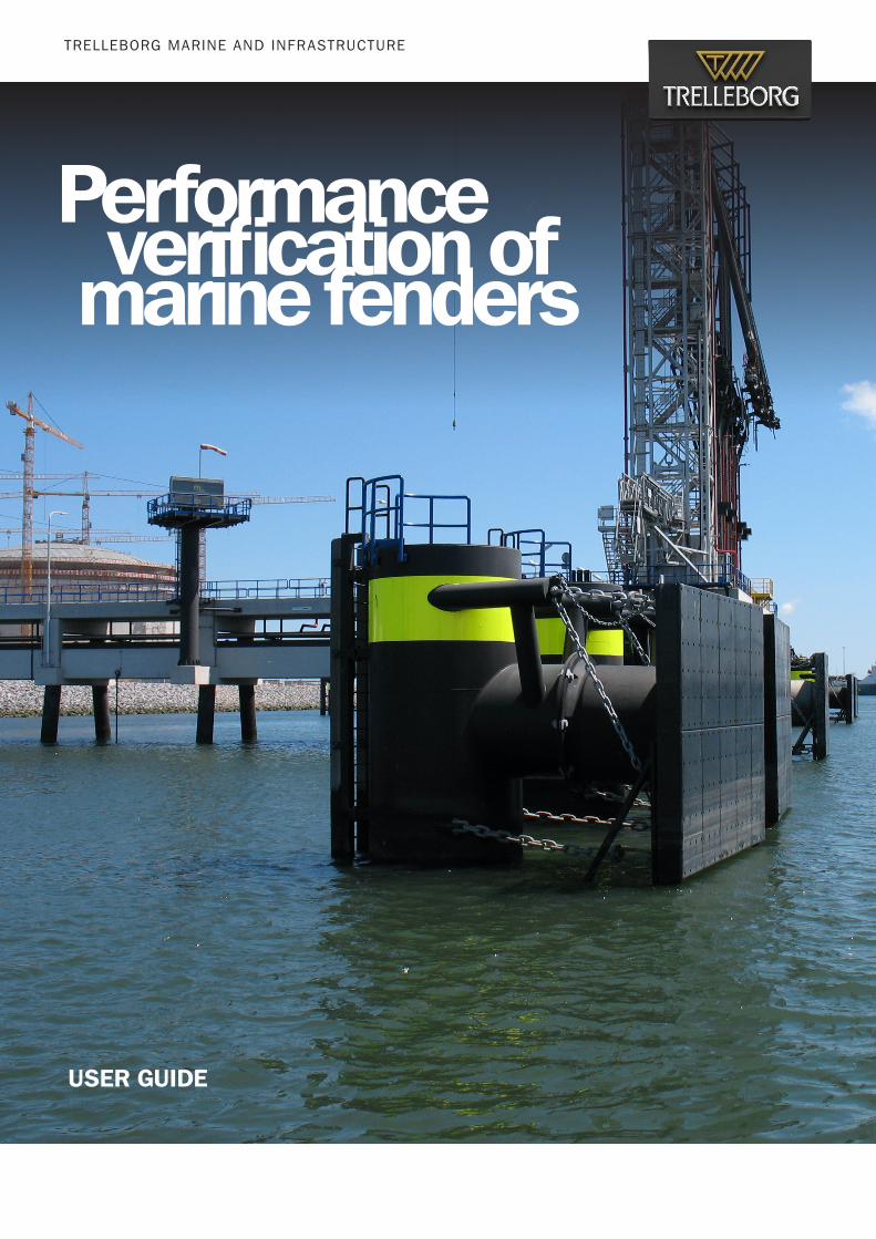
A clear understanding of the purpose of marine fenders is important for correctly performing the selection and verification process.
The concept behind using fenders is fundamentally simple and easy to understand. Here’s why they are used:
❙ Primarily, fenders are used to absorb the kinetic energy of incoming vessels
❙ Fenders provide a known reaction load for the design of the wharf
❙ Fender Systems also ensure safety by protecting the vessel as well as the wharf
❙ Fenders are easily replaceable components between the vessel and the wharf
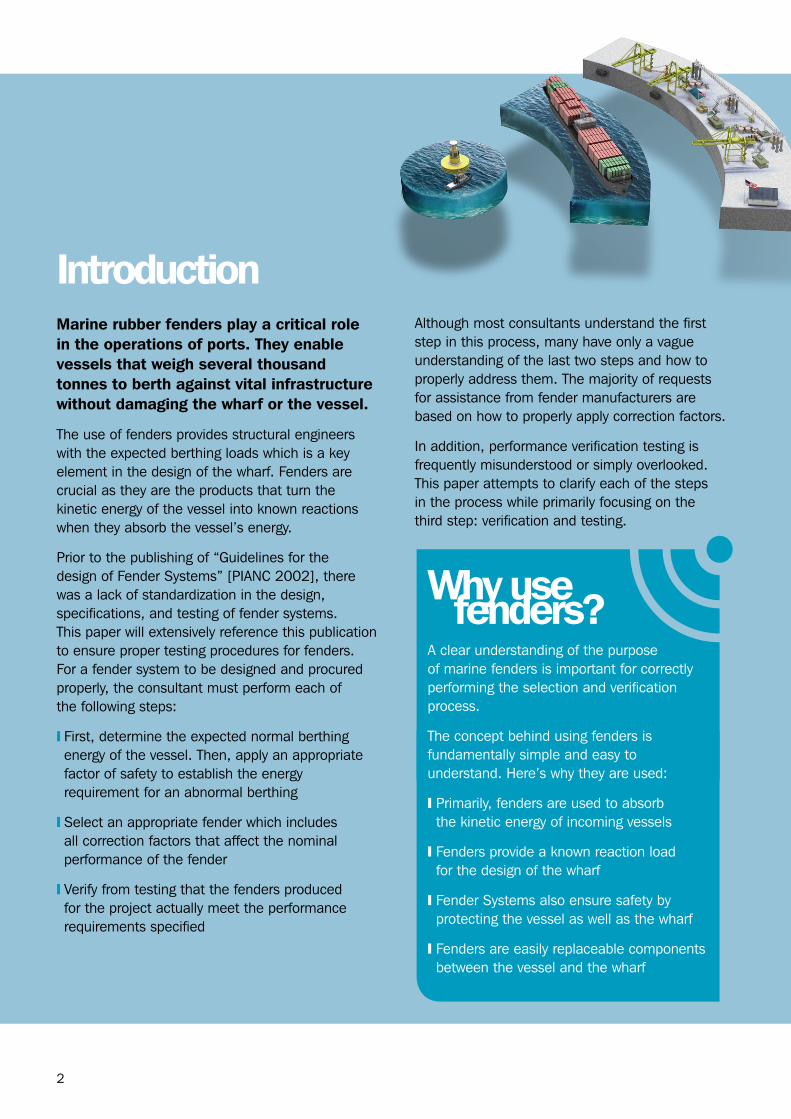
Marine rubber fenders play a critical role in the operations of ports. They enable vessels that weigh several thousand tonnes to berth against vital infrastructure without damaging the wharf or the vessel.
The use of fenders provides structural engineers with the expected berthing loads which is a key element in the design of the wharf. Fenders are crucial as they are the products that turn the kinetic energy of the vessel into known reactions when they absorb the vessel’s energy.
Prior to the publishing of “Guidelines for the design of Fender Systems” [PIANC 2002], there was a lack of standardization in the design, specifications, and testing of fender systems. This paper will extensively reference this publication to ensure proper testing procedures for fenders. For a fender system to be designed and procured properly, the consultant must perform each of the following steps:
❙ First, determine the expected normal berthing energy of the vessel. Then, apply an appropriate factor of safety to establish the energy requirement for an abnormal berthing
❙ Select an appropriate fender which includes all correction factors that affect the nominal performance of the fender
❙ Verify from testing that the fenders produced for the project actually meet the performance requirements specified
Although most consultants understand the first step in this process, many have only a vague understanding of the last two steps and how to properly address them. The majority of requests for assistance from fender manufacturers are based on how to properly apply correction factors.
In addition, performance verification testing is frequently misunderstood or simply overlooked. This paper attempts to clarify each of the steps in the process while primarily focusing on the third step: verification and testing.
Why use fenders?
3
Marine rubber fenders play a critical role in the operation of ports.
If the vessel’s kinetic energy cannot be absorbed by the fenders then where does the energy go? The energy usually goes directly into damaging either the wharf or both the wharf and the vessel, undoubtedly endangering lives and property.
So how can the owner / operator guarantee that the fenders installed at their facility are actually able to absorb the prescribed energy? The current industry practice of verifying the performance of rubber fenders is carried out by the suppliers themselves. The reason this is so readily accepted is that the suppliers are known to own equipment capable of testing such large items. The conflict of interest between the supplier and the port is obvious, especially when considering the high cost of manufacturing some of the world’s largest rubber parts.
This paper discusses a few potential ways that the purchaser of marine fenders can independently verify the fenders and if they are meeting the project specifications – thereby assuring safe berthing operations.
Abstract
4
After a fender system designer determines the estimated energy for an abnormal berthing, it is time to select a fender that can absorb energy that is equal to or greater than the estimate. The selection process is not as straightforward as it seems and it can be confusing for consultants and customers who are not specialists in fenders.
Prior to PIANC 2002, the only factors typically considered in the fender selection process were the effect the compression angle had on the fender’s performance and occasionally the manufacturing tolerance – usually ± 10% of a fender’s catalogue performance. The speed at which the fender was being compressed and the temperature of the rubber fender were two other important factors that were being ignored.
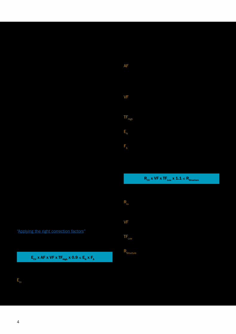
HOW TO SELECT THE RIGHT FENDERThe following equations can be used to determine a fender’s corrected performance. The manufacturing tolerance is assumed to be ± 10%. Additional details can be found within the published whitepaper: “Applying the right correction factors”
ENERGY
ECV x AF x VF x TFHigh x 0.9 ≤ EN x FS
WHERE
Ecv is the nominal catalogue energy capacity of the fender tested at a constant velocity (CV) slow speed (2-8 cm/min).
AF is the manufacturer specific angular correction factor for the effective angle at which the vessel is berthing, or in the case of multiple fender contact, the highest angle at which any single fender is being compressed.
VF is the manufacturer specific velocity correction factor for the speed at which normal berthing occurs.
TFHigh is the temperature correction factor at the highest expected service temperature.
EN is the nominal calculated berthing energy (PIANC 2002 Section 4.2.1).
FS is the factor of safety used to determine the “abnormal energy”. (PIANC 2002 Section 4.2.5).
REACTION
RCV x VF x TFLow x 1.1 ≤ RStructure
WHERE
Rcv is the nominal catalogue reaction of the fender tested at constant velocity (CV) slow speed (2-8 cm/min).
VF is the manufacturer specific velocity correction factor for the speed at which the berthing occurs.
TFLow is the temperature correction factor at the lowest expected service temperature.
RStructure is the design reaction. This is the estimated reaction used in the design of the wharf structure. It is also the suggested reaction used to design the fender panel system and its components.
PIANC 2002, Appendix D details two cases that demonstrate in more detail how to calculate the resulting energy and reaction values when using correction factors.
Selection of fenders

5
Performance verification testing, sometimes referred to as a Factory Acceptance Test, is a test performed on the actual fenders produced for a project. Rubber fenders are almost always manufactured to order as there are too many models, sizes, and grades to keep in stock.
To ensure the fenders were produced correctly and in accordance with the particular specifications of the project, usually 10% of the order quantity is tested. These tests differ from the scale model testing performed to establish catalogue rated performance values, RPD, or for determining the various correction factors which are described in PIANC 2002, Appendix A, sections 1 through 5. Verification testing is testing of “your” fenders, not prototype fenders. This is described in Appendix A, section 6.
HOW TO PERFORM VERIFICATION TEST
Performance verification testing is usually performed in a large press or test frame with either load cells or pressure transducers. These are installed in the hydraulic circuit of the press to measure the load and a displacement transducer to measure the deflection. The sheer size of even a mid-sized rubber fender must be taken into account. Aside from the large specimen size, the testing of rubber fenders requires more stroke, or deflection capability, than most frames can produce.
Around the world, there are only a limited number of publicly available test frames that are capable of testing rubber fenders. For this reason performance verification testing is almost always performed at the manufacturer’s facility. There are obvious reasons that should concern the customer when the manufacturer elects to test their fenders at the manufacturer’s factory. These reasons will be discussed later.
BREAK-IN CYCLES
Before a fender’s performance can be verified, it must first be subjected to a number of break-in cycles. When the fenders are molded, a number of weak or temporary bonds are formed in the rubber that must be broken so that the fenders perform in a repeatable fashion. The first deflection cycle on a newly molded fender is not indicative of the fender’s performance in service. The first cycle in particular can be as high as 30% greater than its actual performance. Once the fender is broken in, it will never achieve these high levels of reaction again.
CONSTANT VELOCITY VS. DECREASING VELOCITY
PIANC 2002 allows for performance verification testing to be performed using either the Constant Velocity (CV) or Decreasing Velocity (DV) methods noted in PIANC 2002 Appendix A, section 4.
Only a very limited number of manufacturers have built full scale dynamic test frames that can simulate actual berthing speeds during the testing of fenders. This is not a problem as PIANC 2002 was written specifically to address the fact that most manufacturers can only perform verification testing using the CV method. If available, testing using the DV method is advantageous as the DV method does not have to be velocity corrected.
HOW CORRECTION FACTORS APPLY TO VERIFICATION TESTING
The correction factors mentioned earlier actually serve another purpose [Figure 1 on page 7]. They may be necessary to correct the performance established during performance verification testing if the fender is tested outside of the required test speed or temperature range.
Performanceverification testing
6
Correction factors are used to modify the fender performance to account for site conditions such as temperature and berthing velocity that vary from the nominal performance of the fender.
Correction factors applied to the performance verification tests are to account for testing conditions that exist at the time of the test. These are usually limited to the effects of temperature and velocity during testing.
Only a few fender test frames are located in climate controlled facilities and even fewer are capable of testing at the actual velocities used to determine the berthing energy.
❙ When selecting a fender, correction factors are used to account for the conditions under which the fender must operate that differ from the nominal catalogue rated performance
❙ When performing verification testing of a fender, the correction factors are used to modify the test results so that the fender’s nominal performance can be determined
PIANC 2002 recommends that performance testing using the CV method be performed at a speed of 2 to 8 cm/min and with a temperature range of 23°C ± 5°C. If the performance verification test is completed outside of either of these parameters, the results must be corrected so that the results reflect the fender’s nominal performance. How the test results are corrected depends on how the fenders were rated.
If the fender’s catalogue rated performance is published using PIANC RPD values based on the recommended 150 mm/s compression speed, then the results must be velocity corrected to determine the catalogue rated nominal performance within tolerances. If the fender’s catalogue rated performance is based on CV test results, then no velocity correction is necessary as long as the verification test velocity was between 2 to 8 cm/min.
If the corrected performance verification test results meet the nominal performance of the fender within manufacturing tolerances then the fender is assumed to have passed the test.
7
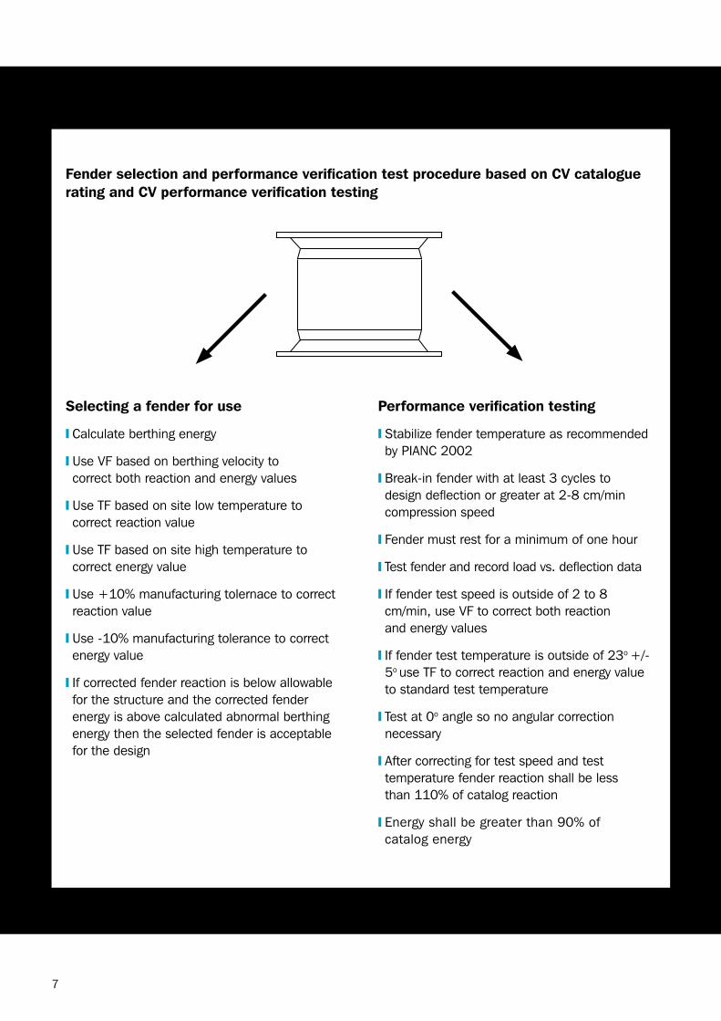
Selecting a fender for use
❙ Calculate berthing energy
❙ Use VF based on berthing velocity to correct both reaction and energy values
❙ Use TF based on site low temperature to correct reaction value
❙ Use TF based on site high temperature to correct energy value
❙ Use +10% manufacturing tolernace to correct reaction value
❙ Use -10% manufacturing tolerance to correct energy value
❙ If corrected fender reaction is below allowable for the structure and the corrected fender energy is above calculated abnormal berthing energy then the selected fender is acceptable for the design
Fender selection and performance verification test procedure based on CV catalogue rating and CV performance verification testing
Performance verification testing
❙ Stabilize fender temperature as recommended by PIANC 2002
❙ Break-in fender with at least 3 cycles to design deflection or greater at 2-8 cm/min compression speed
❙ Fender must rest for a minimum of one hour
❙ Test fender and record load vs. deflection data
❙ If fender test speed is outside of 2 to 8 cm/min, use VF to correct both reaction and energy values
❙ If fender test temperature is outside of 23o +/-5o use TF to correct reaction and energy value to standard test temperature
❙ Test at 0o angle so no angular correction necessary
❙ After correcting for test speed and test temperature fender reaction shall be less than 110% of catalog reaction
❙ Energy shall be greater than 90% of catalog energy
Figure 1 - Fender selection and verification testing workflow.
8
Fender designers are not always aware of the consequences of installing a fender that does not meet the specifications.
There are two primary concerns if the fender being installed does not match the specifications: the energy absorption being below the specified value and the reaction being above the specified value.
ENERGY ABSORPTION BELOW SPECIFIED VALUE
When the fender is incapable of absorbing the specified energy it is very likely the wharf will experience loads much higher than anticipated. The kinetic energy of the vessel must go somewhere, it cannot simply disappear. When a fender does not have adequate energy capacity it will undergo an extreme increase in reaction with very little additional deflection.
Since energy is defined as the product of reaction and deflection, the additional energy absorbed is
Ramifications of outof specification fendersvery little when the fender is compressed beyond its design reaction. In this instance, in order to absorb the excess energy something else must deflect and it has to be either the vessel hull or the wharf.
Since neither the vessel hull nor the wharf itself is intentionally designed to deflect, there is a slim chance that they will do so in the elastic range.
REACTION ABOVE SPECIFIED VALUE
When the fender being installed is above the specified reaction there is the possibility that the wharf will see unacceptable reactions. A fender with high stiffness can have as much as twice the reaction of a fender with low stiffness. Given that live load factors are usually 1.6, it is quite easy for the fender to produce reactions far in excess than that anticipated. This has very serious consequences for load sensitive structures such as fenders installed on monopiles.

9
There are several serious concerns with the way fender performance verification testing is currently performed.
Some of these concerns involve the authenticity of the reported performance as very little thought is given to the need for independent certification of the reported test results.
WHY VERIFICATION TESTING CANNOT BE LEFT TO THE MANUFACTURER
When testing is performed at the manufacturer’s factory, the fender being tested can easily be specifically selected for the test as opposed to being randomly selected. Manufacturers can build special test fenders that will pass the tests while building the rest of the fenders with substandard materials. Testing results can also be manipulated for commercial reasons. It is much cheaper to build low quality fenders that do not meet the performance requirements and manipulate the test results instead of building every single fender to meet the requirements.
Our recommended ‘TGA’ test for rubber quality is certainly useful in addressing this issue to a great extend. (Please refer to our Fender Application Design Manual for more information on the TGA test.)
AN UNDISCLOSED TRUTH ABOUT WITNESSED TESTING
The common practice in the industry is to rely on factory testing that is witnessed by either a third party or by the consultant. However, there are several reasons why this is inadequate. Primarily, there is no easy way for a witness to verify the results independently of what the manufacturer is reporting. Modern data acquisition methods rely on computers to interpret the data
and produce a report. The witness rarely has any understanding of how the data acquisition system functions. It is extremely easy for the manufacturer to manipulate the recorded data in the computer without the witness’ knowledge.
Many project specifications require a third party inspection agency to witness the test. Unfortunately, these agencies are not doing anything more than that. They are simply witnessing a test. They do not provide any oversight on how the test data was acquired or if the report they are asked to endorse is even from the test they just witnessed. The inspection agencies are not in any way guaranteeing the validity of the data they are endorsing. If the data being validated and presented to the customer for acceptance cannot be guaranteed then what useful purpose does the test serve?Independent construction materials testing is a common practice in the construction business. Why is it not standard practice in the verification of fender performance when it has such a critical effect on safety and protection and valuable assets?
“TRUST BUT VERIFY” – BUT HOW?
Independently verifying fender performance during the performance verification test is not an easy task, but it is imperative if the specified performance of the fender is to be guaranteed. Independent verification testing is possible with any one of the following methods:
❙ Testing at an independent structural laboratory
❙ Testing at the manufacturer’s factory using their test frame but with independently recorded performance data
Each of the two methods has its advantages and disadvantages.
The problems with currentindustry testing practices
10
INDEPENDENT LABORATORY TESTINGTesting at an independent structural laboratory is the easiest method to verify performance. These laboratories have large test frames capable of generating high loads on large specimens.
ADVANTAGES
❙ The laboratory is a third party testing laboratory that has no incentive to manipulate the results
❙ No purchase of additional equipment is usually needed to perform the test
❙ The laboratories are often located in climate controlled buildings eliminating the need to accommodate changing temperature conditions or having to deal with weather. Therefore, no temperature correction of the results is necessary
❙ The results, including raw data, can be available for review by the consultant or the end user
❙ Laboratories are often nationally accredited
DISADVANTAGES
❙ There is a limited number of such test laboratories available globally
❙ Time must be allowed in the schedule for the fender test specimens to be delivered to the testing laboratory – which could be quite far from the jobsite
❙ The fenders to be tested should be from the full lot delivered to site to avoid the manufacturer attempting to prepare special fenders for testing purposes
❙ There is a cost associated with testing, but the costs for a project of reasonable size are usually only 2% to 4% of the value of the fender contract
❙ There is a limit to the amount of stroke on any test frame. Fenders can have unusually high deflection requirements and exceed the abilities of even the largest test frames
MANUFACTURER’S FACILITY TESTINGManufacturers are accustomed to the specific needs of fender testing and are already setup to easily test fenders at their factories.
ADVANTAGES
❙ The large test frame needed to compress the fender is available
❙ It is convenient as the fenders are usually made in the same factory, so there are no logistics to consider
❙ Other inspections of the fenders such as build quality and dimensions can occur during one inspection visit
DISADVANTAGES
❙ The consultant or independent inspector has no way to verify that the data being generated during the test is authentic. There are numerous ways in which a manufacturer can manipulate the results without raising any suspicion
❙ The factories are almost all located in faraway foreign countries where even getting there can be problematic. There are potential foreign language difficulties to deal with including the specific language on each of the pieces of equipment used for the test, as well as the computer used to collect the data
There is simply too much of an incentive for the manufacturer to just “make it pass” when such large contracts at high dollar amounts are at stake.
11
Conducting tests in an independent laboratory is the simplest way to get trustworthy results as the industry moves towards true independent testing rather than just witnessed testing.
This is assuming that there is an available and convenient laboratory to use and customers are willing to dedicate the time and money to carry out the testing at one of these laboratories.
The long term goal for the industry should be for manufacturers to offer testing at their own facilities but with results guaranteed to be independently recorded and certified by an inspection agency. Doing this will require the industry to adopt standards and methods that are easy to implement, cost effective, and easy to understand by independent inspectors and consultants.
The industry should set up a PIANC or ISO working group to specify how third party inspection companies can verify performance, not just witness it.
RECOMMENDATIONS
It is recommended that the user does not rely on simple witness testing to determine fender performance. The person witnessing the performance verification test probably knows less about fenders than the purchaser.
A new means of verifying the load vs. deflection data outside of the control of the fender manufacturer must be established. Real-time data should be shown on an external display and the results should be printed in real-time so the witness has direct access to the data. This method is only useful if the load sensing system is calibrated by an independent agency directly before the performance verification testing.
Ways the industry could offertrue independent testingIn addition, PIANC needs to establish methods and procedures that give confidence in the performance verification results being reported.
Consult with well-known third party inspection agencies to determine the feasibility of offering certified inspectors that understand how to use the independent test equipment. The agency should be able to certify the results, not just serve as a witness to the testing.
12
The process of selecting fender systems and verifying performance is not a difficult subject to master if given the proper attention. Fenders are crucial in protecting both the wharf and the vessel so it is important to have a rigorous procurement process in place to reflect this.
No matter how well the designer understands the fender specification process it will hardly matter if the performance verification testing is not independently verified.
REFERENCESPIANC 2002, Guidelines for the Design of Fender Systems: 2002, Report of Working Group 33 – MARCON, PIANC, Brussels, Belgium.Trelleborg 2015, Applying the Right Correction Factors, Trelleborg Marine Systems, www.trelleborg.com/marine.
Summary andconclusions

Trelleborg Marine SystemsEmail: [email protected]
WWW.TRELLEBORG.COM/MARINE
twitter: @MarineInsightsyoutube.com/user/TrelleborgMarine
flickr.com/photos/MarineInsightslinkedin.com/MarineInsights
MarineInsightsBlog.Trelleborg.com
Trelleborg is a world leader in engineered polymer solutions that seal, damp and protect critical applications in demanding environments. Its innovative solutions accelerate performance for customers in a sustainable way.