Embed Size (px)
Citation preview

Performance Testing of SHP StationsA Guide for Developers, Manufacturers and Consultants
Supported byMinistry of New and Renewable Energy
Government of IndiaNew Delhi
Implemented byAlternate Hydro Energy Centre
Indian Institute of Technology RoorkeeRoorkee-247 667
De
ce
mb
er
20
09

Performance Testing of SHP Stations A Guide for Developers, Manufacturers and Consultants
Supported by
Ministry of New and Renewable Energy Government of India
New Delhi
Implemented by
Alternate Hydro Energy Centre Indian Institute of Technology Roorkee
Roorkee-247 667
December 2009

Published by:- Dr. Arun Kumar Head Alternate Hydro Energy Centre Indian Institute of Technology Roorkee Roorkee-247 667 Phone : +91 1332 274254, 285213 Fax : +91 1332 273517, 273560 E-mail : [email protected], [email protected]
DISCLAIMER
This publication aims at disseminating information on the objective and scope of performance testing of small hydropower stations, policy of the Government of India in this regard and the institutional arrangements made by the Government for implementation of the policy through AHEC, IIT Roorkee, for the benefit of small hydropower producers, equipment manufacturers, consultants, government utilities, financial institutions and policy makers. It describes with illustrations the provisions required in the power station for carrying out performance tests.
AHEC, IIT Roorkee does not accept any liability for errors and omissions in this
publication or for any consequences of using the information contained herein by any person or organization.
The contents of this publication may be used freely with due acknowledgment.
This booklet may also be downloaded from website: www.iitr.ac.in/departments/AH/uploads/File/Performance_testing_brochure.pdf

lfpoHkkjr ljdkj
uohu vkSj uohuhdj.k ÅtkZ ea=ky;SECRETARY
GOVERNMENT OF INDIAMINISTRY OF NEW AND RENEWABLE ENERGY
CykWd ua- 14] dsUnzh; dk;kZy; ifjlj] yksnh jksM] ubZ fnYyh&110003Block No. 14, CGO Complex, Lodi Road, New Delhi - 110 003
Tel. : 011-24361481, 24362772 Fax : 011-24367329 E-mail : [email protected]��
lR;eso t;rs
nhid xqIrkDeepak Gupta
nhid xqIrkDeepak Gupta
FOREWORD
Ministry of New and Renewable Energy Sources is giving high priority to quality andreliability of small hydro power projects. Adopting quality standards are-extremely importantnot only for life of small hydro projects but also for their overall economic viability. With theintroduction of performance testing of SHP stations as mandatory to receive subsidy fromMNRE in 2003, all SHP projects are required to follow BIS/IEC standards in construction andequipment and meet the requirements in terms of standards, specifications and performanceparameters.
Alternate Hydro Energy Centre (AHEC), IIT Roorkee is well equipped with-theperformance testing and evaluation facilities for the small hydro power stations. The need forcomprehensive set of instructions on performance testing for different users has been felt forsome time now. I am glad that this gap is now sought to be bridged through the publication ofset of such instructions.
I would like to complement AHEC for bringing out this publication titled 'PerformanceTesting of SHP Stations-A Guide for Developers, Manufacturers and Consultants' with theillustrations for making provisions by the consultants, manufacturers and contractors indifferent components of a small hydropower station for conducting performance testing at siteafter; gaining the experience of different types and capacities SHP stations during last 4 years.
I am confident that this publication will be of immense use to all stakeholdersassociated with SHP development for maximizing the energy generation from the given waterresource in the country.
(Deepak Gupta)
v{k;
≈tkZ ls ns'k fodkl
xkao xkao fctyh] ?kj ?kj çdk'k
i

December 11, 2009
Technical institutes and universities are the backbone of technical education, research,
development and training in any country. Academic – industry interaction inter-alia support is a
need of the hour. This interaction in general leads to cost effective solutions.
I am happy to learn that theAlternate Hydro Energy Center of our institute has been entrusted the
task of conducting performance testing and evaluation for small hydropower stations in the
country by the Ministry of New and Renewable Energy, Govt. of India.
IIT Roorkee with its multi disciplinary team of experts, with networking with Jadavpur
University Kolkata, MANIT Bhopal and BRANIT Jallandhar, has come up to the expectation
in providing technical support to the small hydropower industry and has also conducted tastings
of over 40 SHPstations in a short span of 4 years.
Based on these experiences, Alternate Hydro Energy Center of IIT Roorkee has prepared a
manual titled “Performance Testing of SHP Stations – A Guide for Developers, Manufactures
and Consultants”.
I understand that the publication of these guidelines shall be highly useful to all involved in the
development of SHPin the Country.
MESSAGE
(S. C. SAXENA)
Hkkjrh; izkS|ksfxdh laLFkku #M+dh#M+dh & 247 667] (mÙkjk[k.M) Hkkjr
INDIAN INSTITUTE OF TECHNOLOGY ROORKEE
ROORKEE - 247 667, (UTTARAKHAND) INDIA
Tel : , , ,Fax :e-mail : . . . .
+91- 1332-272742 285500 (O) 272342 285400 (R)+91-1332-273560,director@iitr ernet in, saxenasuresh@yahoo co in
285815 (O), 285300 (R)
çks0 ,l0 lh0 lDlSukfuns'kd
Prof. S. C. SAXENADirector

ii
PREFACE Any small hydropower (SHP) station, which has been duly installed and commissioned, should be tested by a third
party to confirm that all its parts and systems are performing their assigned functions correctly and that the generating units are operating efficiently. However, the testing needs professional skills and expertise of very high order and the costs of hiring such expertise and necessary test equipment from a test house may be prohibitive.
The Ministry of New and Renewable Energy (MNRE), Government of India, with its concern to improve the quality and performance of SHP stations in the country, felt for long a need to create a system of performance evaluation by a neutral agency at low costs. In July 2003, the MNRE (at that time known as Ministry of Non-conventional Energy Sources - MNES) issued a notification linking its subsidy support for SHP projects to their performance. The Alternate Hydro Energy Centre (AHEC) of the Indian Institute of Technology Roorkee (IITR) was identified as the test agency for this purpose. This was done for two reasons: Firstly, AHEC has a long and vast experience in SHP, right from pre-feasibility, surveys and investigations for preparation of DPRs and designing the complete SHP stations. Secondly, it has the support of highly qualified and experienced faculty of IITR in every related discipline, be that hydraulics, hydrology, fluid dynamics, hydraulic machinery, electrical machines, power plant design, control or instrumentation.
Under the aforesaid scheme announced by MNRE in 2003, the Ministry supported the entire one-time cost of the test equipment required for the performance testing, which are highly sophisticated and expensive. By doing so, MNRE subsidised the cost of performance testing and made it affordable for the smallest SHP project owner.
At IITR, a multi-disciplinary team was formed to carry out performance testing of SHP stations, and necessary portable test equipment was procured out of the funds provided by MNRE. The charges for testing small hydropower stations were fixed in consultation with MNRE. By now this multi-specialty group has carried out performance testing of over 40 SHP stations of different types and capacities and in different parts of the country.
As the performance testing is expected to be carried out in various parts of this vast country on a large number of
SHP stations every year, IITR has associated experts from some reputed institutions, namely Jadavpur University at Kolkata, Maulana Azad National Institute of Technology at Bhopal and Dr B R Ambedkar National Institute of Technology at Jalandhar. The coordination of the entire activity is done by AHEC, IITR.
This information brochure explains the objective, scope and methodology of performance testing and gives a list of the relevant national and international standards. For the convenience of the power station owners, formats for supplying the power station and generation data and the fee schedule for testing are also included. Soft–copy of the formats are available on www.iitr.ac.in/departments/AH/uploads/File/Performance_testing_brochure.pdf
An information booklet titled “Performance Testing of SHP Station” was published by AHEC, IIT Roorkee in June
2005 and circulated all the users and stakeholders. Now, on the basis of rich experience of the test-team with different installed capacities, unit sizes, types, heads, discharges and levels of automation, detailed guidelines have been prepared for the SHP developers, equipment manufacturers and consultants to help them to make certain provisions in the SHP stations / equipment, which are necessary to conduct the performance testing. The same are being published in this revised and enlarged version of the booklet.
Dr. Arun Kumar Head Alternate Hydro Energy Centre Indian Institute of Technology Roorkee Roorkee-247 667 Phone : +91 1332 274254, 285213 Fax : +91 1332 273517, 273560 E-mail : [email protected] [email protected]
Dr. H.K. Verma
Professor of Electrical Engg. and Deputy Director
Indian Institute of Technology Roorkee Roorkee-247 667
Phone : +91 01332 285588, 285571 Fax : +91 01332 273560, 285776
E-mail : [email protected] [email protected]
1
PERFORMANCE TESTING OF SHP STATIONS: OBJECTIVE, SCOPE AND METHODOLOGY
1. OBJECTIVE
Performance testing of a SHP station includes broadly the following: (a) Quantitative checks to confirm that all parts, systems and auxiliaries in the power station are
performing their assigned functions correctly. (b) Measurement and tests to confirm that the generating units are operating efficiently, their
operating, parameters are within reasonable limits and the errors of relays and meters are within specified limits.
2. SCOPE
The overall scope of performance testing is listed below: (a) Inspection of all parts, systems and station auxiliaries. (b) Functional checks on simpler devices and systems. (c) Error checks on measuring instruments. (d) Secondary injection tests on protective relays. (e) Operational checks on control systems. (f) Measurement of the operating parameters of generating units. (g) Measurement of maximum power output of generating units. (h) Measurement of the efficiency of generating units at different, loads.
Thus, performance testing comprises inspection, functional checks, tests, measurements and
analysis as necessary to meet the broad objectives laid down above. Further detailing in respect of the testing of each individual major component/system is given in the following sections. It should be understood that the tests mentioned here are carried out subject to the technical feasibility as well as necessity. Furthermore, detailed diagnostic investigations on any faulty component/system are outside the scope of performance testing.
3. WATER CONDUCTOR SYSTEM
3.1 Overall Inspection
To begin with, the complete water conductor system is inspected to observe any apparent
problems or deficiencies in its design or construction.
3.2 Measurement The following measurements are made, if instruments are already installed in the station, with a
view to make an initial assessment of the working of the power station. (a) Different water levels/pressures (b) Gross head available to turbines (c) Discharge through turbines

2
4. GENERATOR
4.1 Currents and Voltages
The following quantities for each generator are read at different loads on the panel instruments to verify the working of the generators:
(a) Line currents (b) Terminal voltages (c) Power (d) Power factor (c) Excitation voltage / current
4.2 Temperature Rise
Any overheating in the generators would be revealed in the following temperature rise
measurements:
(a) Temperature rise of stator (b) Temperature rise of rotor (c) Temperature rise of cooling medium
5. TURBINE – GENERATOR UNIT
5.1 General Health
Temperature rise, sound level and vibration levels are the good indicators of the general health of any machine. To that end, the following measurements are carried out on each generating unit:
(a) Temperature rise of bearing oil (b) Sound level (c) Machine vibrations
5.2 Maximum Power Output Test
The maximum electrical power output actually available from the generating unit should match the value specified by the manufacturer. The test is conducted at rated head as far as possible.
5.3 Efficiency Test
(a) Unit Efficiency Measurement by Discharge-Head Method
The test aims at determining the absolute (actual) efficiency of the generating unit or the turbine under specified conditions according to IS/IEC-41. It involves measurement of the absolute value of the discharge through the turbine, the net water head available at the turbine and the electrical power output of the machine, all under specified operating conditions and each with high accuracy.

3
Relative discharge can be measured by an recalibrated device. Using the relative discharge values, one can determine relative efficiency values.
IS/IEC-41 specifies the following methods of discharge measurement:
(a) Current-meter method (b) Pitot-tube method (c) Pressure-time method (d) Tracer method (e) Weirs (f) Differential pressure devices (g) Volumetric gauging method (h) Acoustic method
The choice of the method of measurement may be affected, as per IS/IEC-41, by the following
factors:
(a) Limitations imposed by the design of the plant (b) Cost of special equipment and its installation (c) Limitations imposed by plant operating conditions, for example draining of the system,
constant load or discharge operation, etc.
While IS/IEC-41 makes the unit efficiency test mandatory, IEC-61116 (that addresses SHP installations) makes the test optional in the following cases:
(i) The machine size is small not justifying the high cost of performing this test. (ii) The efficiency value is not of real use as the available water flow greatly exceeds the
useable flow. (iii) It is technically difficult to carry out the test.
(b) Turbine Efficiency Measurement by Thermodynamic Method
In the case of SHP stations of high heads (100 m and above), the hydraulic efficiency of the turbine can alternatively be measured by thermodynamic method. It involves accurate measurement of the small temperature rise of water that takes place between intake and outlet of the turbine, but does not require discharge measurement. The overall efficiency of the generating units is determined by assessing the mechanical losses in the turbine, losses in its auxiliaries and losses in the generator.
5.4 Index Test
The test involves measurements of relative discharge and relative efficiency as opposed to the measurement of absolute values. The methods used for measuring the relative discharge are secondary methods. As per IS/IEC-41, the results of the index text should not be used for any contractual consequences, except where both the parties agree.
Relative values are derived from an index value, which is an arbitrary scaled value, by expressing them as a proportion of the index value at an agreed or defined condition.
As per IS/IEC-41, the index test may be conducted for any of the following purposes:

4
(i) To determine the relative variation in the unit efficiency with load or gate/valve opening. (ii) To determine the correct relationship between runner blade angle and guide vane opening
in the case of a double regulated machine. (iii) To provide additional test data during the unit efficiency test.
The relative discharge measurement required for the index test can be made by one of the
following methods:
(i) Measurement of pressure difference between suitably located taps on the turbine spiral case (Winter-Kennedy method).
(ii) Measurement of pressure difference between suitably located taps in tubular turbines. (iii) Measurement of pressure difference between suitably located taps on a bend or taper
section of the penstock. (iv) Single-path ultrasonic transit-time flowmeter. (v) Measurement of needle stroke on pelton turbines. (vi) Measurement by means of a single current meter
6. MEASURING INSTRUMENTS AND INSTRUMENT TRANSFORMERS
6.1 Error Checks
All electrical panel meters (ammeters, voltmeters, kilowatt and power factor meters, energy meters, frequency meters and multi-function meters) are subjected to a limited error check. The readings of these meters at the respective operating points are compared against a portable reference meter to measure their errors at the most important point(s),that is the points around which they are usually required to measure. If a meter is found to have an error beyond its accuracy class, further testing would be desirable.
A similar check is carried out on speed indicator. Comparison may be made against a reference
frequency meter (as also recommended in IEC-60308) because of the high resolution and accuracy of reference frequency meters.
6.2 Functional Checks
In view of the non-critical nature of the parameters measured/recorded and difficultly in placing
transducers, error measurement on the following instruments are normally not carried out. Instead, simple checks on their functioning and validity of their current readings suffice.
(a) Gate / valve / needle position indicators (b) Temperature indicators (c) Temperature scanners (d) Recorders
6.3 Ratio Tests
The CT and VT ratios need not to be tested normally. However, these may be verified, if in doubt, either on-line by measuring the primary and secondary currents/voltages, or off-line by measuring the turns ratio using a digital turns ratio tester with reference to IS-2705 and IS-3156.
5
7. PROTECTIVE RELAYS
7.1 Secondary Injection Tests
A portable secondary injection test set is used to test all the measuring relays (or relay functions of multi-function digital relays/management relays) as per IS-3231. Normally it is considered sufficient to carry out operating-value and operating-time tests (the latter for time delay relays and delay elements only) at the current (prevailing) relay settings. In case of the doubtful working of a relay, a more detailed secondary injection test is conducted. 7.2 Functional Checks
Functional checks are carried out as per IS-3231 on the following parts:
(a) Tripping / master relays (b) Auxiliary relays (c) Fault annunciators
8. CONTROL PANELS AND SYSTEMS
8.1 Control Panels
Before testing control systems, an inspection and functional checks on various parts/accessories of the control panels and desks are carried out to identify the defective parts or accessories, if any.
8.2 Regulation / Control Systems
The following regulation and control systems, if used, are tested to verify their overall
functioning: (a) Flow regulation (b) Level regulation (c) Field regulation (d) Manual synchronization (e) Automatic synchronization (f) Manual start/stop sequences (g) Automatic start/stop sequence (h) Emergency stop sequence
9. GOVERNOR The governor, being one of the most critical control systems in the power plant, is subjected to
the following tests: (a) All functions of the governor (b) Load rejection or over-speed test (c) Governor sensitivity test (d) Governor stability test

6
(e) Oil temperature test (f) Pressure tank capacity test
The tests at (c) to (f) can be conducted only if the necessary test provisions are available and the
data on parameters/characteristics are already available from commissioning-test records for verification. The tests are conducted generally as per IEC-61116 and IEC-60308. 10. EXCITATION CONTROL SYSTEM
The voltage regulator and excitation system are subjected to the following tests: (a) All-functions of AVR (b) Excitation control stability test (c) Excitation system ceiling voltage (d) Excitation system response ratio (e) Excitation system response time The tests at (c) to (e) can be carried out only if necessary test provisions are available and the
specified values of the parameters are available for verification. The tests are carried out generally as per IEEE-421A.
11. POWER TRANSFORMERS
11.1 Temperature Rise
Of all the major power equipment in a power station, the power transformers are least
troublesome. Unless a problem has been experienced with a transformer, its general condition is checked simply by measuring the temperature rise of the main and conservator tanks.
11.2 Ratio Test
If there is a reason to doubt the transformer ratio (possibly due to shorted turns), transformer
ratio test can be carried out. A portable digital turns ratio tester can measure this ratio with a high accuracy. However, the test requires a shutdown and complete isolation of the power transformer from the system.
12. STATION AUXILIARIES
A thorough inspection of all the station auxiliaries is carried out to verify that these are
functioning normally. They may include station AC supply, station DC supply, oil pumping units, cooling systems, vacuum pumps, air compressors, drainage system, dewatering system, earthing system(s), equipment handling crane, hoists etc.
13. METHODOLOGY
The performance testing of a SHP station is carried out in five stages as follows:

7
13.1 Power Station and Generation Data
All important data and drawings of the SHP station, needed for inspection, checking and testing of the power station, are obtained from its owner. Information showing conformity of the major plant equipment and components to the Indian/International standards is an important part of the station data. The owner can collect this data from the design consultant, contractor and equipment manufactures concerned as well as his own records. In addition, the daily generation data for the period starting with commissioning date and the month-wise projected generation as per DPR are obtained from the owner.
13.2 Planning
Based on the data and drawings obtained, the test agency then plans inspection, checks and tests
that need to be carried out, and prepare a complete schedule of checks/tests. Constraints like non-availability of provisions for certain difficult tests, like index test and unit efficiency test, and inadequacy of water etc. can adversely affect the accuracy and timing of tests. Where necessary, the site is visited in advance for ascertaining the best possible methods of measurements.
13.3 Instrument Checking / Recalibration
The test instruments are checked /recalibrated before taking to the site or at the site, as necessary,
to ensure they are fit for conducting the tests at site. 13.4 Site Tests
Inspection, functional checks and tests in the power station are then conducted as per the
schedule. As far as possible, the vital parameters like discharge and head are measured by two independent methods.
13.5 Test Report
Finally, a test report is prepared. For each major test or measurement, the report mentions the
method and instrument used alongwith the test results. For critical measurements, an assessment of the uncertainties of measurement is made. Remarks and conclusions on the test results alongwith recommendations are given for the benefit of the end users of the report.

8
LIST OF RELEVANT STANDARDS
1. IEC - 60041 (1991): “Field Acceptance Tests to Determine the Hydraulic Performance of Turbines, Storage Pumps and Pump Turbines”.
2. IS/IEC - 41 (1994): “Field Acceptance Tests to Determine the Hydraulic Performance of Turbines, Storage Pumps and Pump Turbines”.
3. IEC - 61116 (1992): “Electromechanical Equipment Guide for Small Hydroelectric Installations”.
4. IEC - 60545 (1976): “Guide for Commissioning, Operation and Maintenance of Hydraulic Turbines”.
5. IS - 12800 (1991): “Guidelines for Selection of Hydraulic Turbine, Preliminary Dimensioning and Layout of Surface Hydroelectric Power Houses - Part 3: Small, Mini and Micro Hydroelectric Power Houses”.
6. IEC - 60308 (1970): “International Code for Testing of Speed of Governing Systems for Hydraulic Turbines”.
7. IEEE- 421(1972), “Criteria and Definitions for Excitation Systems for Synchronous Machines”. 8. IEEE - 421A (1978): “IEEE Guide for Identification, Testing and Evaluation of the Dynamic
Performance of Excitation System”. 9. IEC- 60308(1970), “International Code for Testing of Speed Governing Systems for Hydraulic
Turbines”. 10. ASME PTC- 29(2005), “Performance Test Code for Speed-Governing Systems for Hydraulic
Turbine-Generator Units”. 11. IEC- 34-1 (1983), “Rotating Electrical Machines: Part-1: Rating and Performance”. 12. IS 4722 (2001): Specification for Rotating Electrical Machines. 13. IS - 3231 (1965): “Specification of Electrical Relays for Power System Protection”. 14. IS- 8686(1977): “Specification of Static Protective Relays”. 15. BS-142 (1966): “Specification of Electrical Protective Relays”. 16. IS - 11726 (1985) / ISO 2954 (1975)??: “Requirements for Instruments for Measuring Vibration
Severity of Rotating and Reciprocating Machines”. 17. ISO-10816-1 (1995), “Mechanical Vibration – Evaluation of Machine Vibration by
Measurements on Non-Rotating Part-1: General Guidelines” 18. IS - 11727 (1985, Reaffirmed 1966): “Measurement and Evaluation of Vibration Severity in Situ
of Large Rotating Machines with Speed Range from 10 to 200 rev/s”. 19. ISO-2954 (1975): “Mechanical Vibration of Rotating and Reciprocating Machinery -
Requirements for Instruments for Measuring Vibration Severity”. 20. IEC- 60034-9 (1997), “Rotating Electrical Machines – Part 9: Noise Limits”. 21. IS - 2705 (1992, Reaffirmed 1997): “Specifications of Current Transformers: Part 1: General
Requirements, Part 2: Measuring Current Transformers, Part 3: Protective Current Transformers, and Part 4: Protective Current Transformers for Special Purpose Applications”.
22. IEC- 60185(1987), “Current Transformers”. 23. IS - 3156 (1992): “Specification of Voltage Transformers”. 24. IEC- 186 (1987): “Voltage Transformers”. 25. IEC - 62271 (2008): High-Voltage Switchgear and Controlgear - Part 100: Alternating Current
Circuit-Breakers. 26. IEC - 61362 (1998): “Guide to Specification of Hydraulic Turbine Control Systems”. 27. IS - 2026 (1997): “Power Transformers: Part 1 – General”. 28. IEC- 60255-6 (1988): “Electrical Relays - Part 6: Measuring Relays and Protection Equipment”.

9
FORMAT OF POWER STATION DATA TO BE SUPPLIED BY OWNER
(1) To be provided by the Power Station Owner interested in Performance Testing, to AHEC, IIT Roorkee
(2) Equipment supplier/contractor may be consulted to obtain relevant information/drawing if not available with the owner
(3) Soft copy of these format sheets can be obtained from AHEC or downloaded from: www.iitr.ac.in/departments/AH/uploads/File/Performance_testing_brochure.pdf
(4) Please do not leave any column blank, write NA for Not Applicable and DNA for “Data Not Available”.
(5) Please note that unless the mandatory information (wherever indicated) is provided, testing will not be taken up.
A. GENERAL (mandatory information)
1. Name of Power Station: 2. Owner of Power Station:
(with tel/fax/email and postal address) 3. Location (Enclose location/route map)
Nearest Town with Distance: District: State: Longitude: Latitude: Altitude:
4. Nearest Guest-House/Hotel (with address and distance):
5. Type of Power Station (Run-of-River/Dam based/Canal based): 6. Source of Water: 7. No. of Generating Units with Capacities: 8. Maximum and minimum head: 8. Commissioning Date (for each unit):
B. GENERATING UNITS (mandatory information)
1. Turbine Type: Shaft (Vertical/Horizontal): Make: Rated Head: Rated Discharge: Rated Power Output: Rated Speed: Speed Increaser Used (None/Gear Box/others): Flywheel Provided? (Yes/No): Pressure Taps Provided? (Yes/No):
If yes, Number: Size: Locations: (Enclose drawing/photograph)

10
2. Generator Make: Type (Synchronous / Induction): (select one) Rated Speed: Generator Ratings: ______ kW, ____ pf, ____ kVA, ____ Hz,
____ kV, Y or D connected stator windings Designed Overloading (%): Run-away Speed: Excitation System (Brushless/Static/Brush-type) : (select one) Exciter Ratings:
3. Voltage Regulator:
Type (Digital / Analog): (select one) Make: Response Time: Sensitivity:
4. Governor
Type (Digital /Analog/PLC): (select one) Make: Response Time: Sensitivity:
5. Main Inlet Valve
Make: Type: Closing time:
6. Guide Vanes/Wicket Gates/Nozzles
Device (Guide vanes/wicket gates/Nozzles): (select one) Number: Closing time:
7. Efficiency of Generating Units
(Enclose efficiency curves/data for turbine and generator from the manufacturers)
8. Any problem observed? If yes, give details: Turbine: Generator: Main Inlet Valve: Speed Increaser: Governor: Exciter: Voltage Regulator: Bearings: Others:

11
C. WATER CONDUCTOR SYSTEM (Enclose relevant drawings for applicable components) (Mandatory information) 1. Details of weir: Type, dimensions, inlet gate, design discharge for power generation,
design, flood discharge 2. Details of desilting tank: Discharge, dimensions, number of outlets and sizes 3. Head-Race Details: Length, cross section (Width, depth, side slopes) lining, discharge 4. Details of forebay tank: dimensions, number of outlets, sizes, trash rack arrangement, 5. Details of surge tank: Type and dimensions, 6. Tail-Race Details: Length, cross section (Width, depth, side slopes) lining, discharge 7. Designed Discharge for power house (in m3/s): 8. Single Intake or Individual Intakes for Machines:
9. Number and Type of Intake Gates:
Type: No. of intake gates per turbine Total no. of intake gates Size Type of hoisting
10. Number and Type of Draft Tube (DT) Gates:
Type: No. of DT gates per turbine: Total no. of DT gates: Size Type of hoisting
11. Common Penstock
Length: Inside Diameter : Thickness: Material: No of bends
12. Individual Penstocks
Length: Inside Diameter : Thickness (various): Material:
13. Spilling Arrangement and Discharge Capacity
D. DISCHARGE MEASUREMENT PROVISIONS (mandatory information)
1. Do you measure discharge? (Yes / No):
If no, how do you know the discharge? If yes,
How frequently?

12
By what method? Location of Measurement : Details of Instrument/Method :
(Enclose drawing / photograph)
2. Do you have provision for relative discharge measurement? (Yes/No): If yes,
Method used (Taper section/Winter-Kennedy/others): Details:
(Enclose drawing/photograph) E. HEAD / LEVEL MEASUREMENT PROVISIONS (mandatory information)
1. Do you have provisions for head or pressure measurement? (Yes / No):
If yes, Location: Method/ instrument Used: Size of pressure taps : Location of pressure taps:
(Enclose drawing / photograph)
2. Do you have provisions for measurement of free water level? (Yes / No): If yes,
Locations: Method/ Instrument Used:
(Enclose drawing / photograph)
3. Whether reference elevations marked? (Yes / No): If yes,
Location (Machine floor/others): Levels above MSL (in m):
4. Whether elevation of Centre-line of Penstock Marked? (Yes / No):
If yes, its level (in m): 5. Whether elevation of Centre-line of Turbine Marked? (Yes / No):
If yes, its level (in m): F. POWER CIRCUIT/EQUIPMENT
1. Single-line Power Diagram of Power Station: Please enclose 2. Power Transformers Individual Unit Transformers or Common Transformer?: Make: Number of Transformers: Transformer Ratings: Winding Connections: Cooling type:

13
Tap Changer Type (Off-load/on-load): (select one) Tap changer make: Any Problem Observed? If yes, give details:
3. Auxiliary (Station) Transformers Make: Number of Transformers: Ratings: Cooling type: Location:
G. INSTRUMENTATION 1. Details of Panel Meters
Sl. No.
Panel Name Meter Name & Make
Analog (A) or Digital (D)?
Range Accuracy Class
Quantity
2. Details of Temperature Scanner (if any): 3. Details of Recorders (if any): 4. Details of Data Acquisition System (if any): 5. Details of Test Terminal Blocks, if provided
Sl. No. Name of panel Location of TTB: Inside/Outside panel ?
6. Details of Current Transformers
Sl. No.
Location Measuring or Protection CT?
CT Ratio Accuracy Class

14
7. Details of Voltage (Potential) Transformers:
Sl. No.
Location Measuring or Protection V.T.?
V.T. Ratio Accuracy Class
H. PROTECTION SYSTEM (Enclose relevant panel drawings) 1. Details of Measuring Relays
Sl. No.
Name of Panel Name of Relay Make
Model
2. Details of Auxiliary / Master/Trip Relays
Sl. No.
Name of Panel Name of Relay Make Model
3. Details of Circuit Breakers
Sl. No.
Breaker Name Breaker Type (Air/Oil/SF6)
Breaker Location
Make Model

15
4. Details of Fault Annunciators (FA)
Sl. No.
Name of Panel Microprocessor or Relay type?
Make of FA
No. of Facia Windows Total number
Number used
I. DETAILS OF STATION / PLANT AUXILIARIES:
Sl. No.
Name of Auxiliary Particulars/Ratings/Make/Quantity
1. Station AC Supply 2. Station DC Supply 3. Oil Pumping Units 4. Bearing Cooling System 5. Generator Cooling System 6. Transformer Cooling System 7. Vacuum Pumps 8. Air Compressors 9. Drainage System 10. Dewatering System 11. Equipment Handling Crane 12. Hoists 13. (Others)
J. DETAILS OF ANY OTHER EQUIPMENT not covered above (like SCADA) or any other
information relevant to the Performance testing of your Power Station: K. FLOW DURATION CURVE: Enclose a photocopy of the flow duration curve and data as
included in the DPR (mandatory information). L . TESTS CONDUCTED AT SITE, IF ANY (Enclose report) M. DATA REGARDING CONFORMITY TO STANDARDS (mandatory information)
Sl. No.
Name of equipment Make Relevant standard
Test Report or Certificate available? (Yes/No)
Certification Mark available on the equipment? (Yes/No)
1. Turbines 2. Generators 3. Power Transformers 4. CTs 5. VTs

16
6. Protective Relays 7. HT Circuit Breakers 8. LT Circuit Breakers 9. PLC 10. SCADA System 11. Governor 12. Excitation System 13. AVR 14. Auto Synchronizer 15. Panel Meters 16. Motors 17. Cables 18. Batteries 19. Pumps 20. Crane 21. (Others)
N. DETAILS FOR CLEARANCES OBTAINED FOR PROJECT (mandatory information)
Name of the Clearance Date of application/submission
Date of approval/clearance
1. Power Purchase Agreement 2. Pollution Control 3. Land Acquisition
(a) Forest Land (b) Private Land (c) Gram Panchayat
4. State Irrigation Department 5. Financing Institute (loan) 6. State Nodal Agency for Techno-
Economic Clearance
7. Labour 8. Explosives License 9. Wireless Communication 10. Wild life 11. Fisheries 12. Archaeology 13. PWD 14. (Any other clearance)
O. PERMANENT/TEMPORARY BENCH MARK AT POWER HOUSE
Location: Elevation (in m):

17
P. CHECK LIST OF ENCLOSURES (Please fill in enclosure numbers, such as I, II etc. and mark the same on the enclosures) (mandatory information)
Section No.
Name of enclosure Enclosure No.
A-3 Location map or route map B-1 Drawing/photograph showing pressure taps on turbine
inlet or penstock
B-7 Turbine efficiency curves/data B-7 Generator efficiency curves/data
C
Drawing for general layout of works showing from diversion to tail race
Drawing for L-section of water conductor system Drawing for cross section of power channel, forebay tank, tail race channel
Drawing for details of intake gates Drawing for profile of penstock (plan and section)with details like thickness at each location
Drawing for plan of Power House Building Drawing for X-Section of Power House Drawing for L-Section of Power House showing turbine inlet to outlet
Drawing for plan and section of tail race channel D-1 Drawing /photograph showing provisions for discharge
Measurement
D-2 Drawing /photograph showing provisions for relative discharge measurement
E-1 Drawing/photograph showing provisions for measurement of water head or pressure
E-2 Drawing/photograph showing provisions for measurement of free water level
Photographs Showing diversion weir, diversion channel at few places, intake gates with hoisting and location for fixing the pressure transducer, tailrace channel and exit details of tailrace.
F-1 Single-line power diagram K Flow duration data and curve, as included in DPR L Report of tests conducted earlier, if any
Place: _____________ Date: _____________ Signature: _____________________
Name: _____________________ Designation: _____________________ Seal: _____________________

18
FORMAT OF GENERATION DATA TO BE SUPPLIED BY OWNER
A. Summary of Month-Wise Actual and Projected Generations
Month and Year Actual Total Generation (million units)
Projected Generation as per DPR (million units)
Ratio of Actual- to- Projected Generations (percent)
Remarks (Above or below 80%?)
B. Daily Generation Record for __________________ (specify month & year) (one sheet for each month)
Date
(dd/mm/yy) Machine-wise Actual Generation (in million units) Remarks
Machine#1 Machine#2 Machine#3 Total
Place: _____________ Date: _____________
Signature: _____________________ Name: _____________________ Designation: _____________________ Seal: _____________________
19
GUIDELINES FOR MAKING PROVISIONS IN SMALL HYDROPOWER STATIONS TO FACILITATE PERFORMANCE
TESTING
The IEC Standard 60041 (adopted by BIS as IS/IEC-41) and other standards, relevant to the testing of hydropower stations and plant equipment, emphasize on the accuracy of field test, specially the measurements meant for evaluating the efficiency of generating units. These standards lay down certain requirements in terms of some provisions necessary in the plant equipment and civil works. The Test Team of IIT Roorkee has gained substantial experience in conducting performance tests on small hydropower stations; and the 40-plus stations tested so far, meet these requirements in varying degrees.
It is necessary for the SHP developers to make appropriate provisions for conducting the performance test (a) to ensure conformity of the tests to the standards, (b) to achieve high accuracies and minimize uncertainties of measurements, (c) to reduce effort, time and cost of testing, and (d) to reduce the number and duration of shutdowns needed during testing. Longer shut-downs of the power station result in loss of generation, which can be largely avoided if appropriate provisions for conducting performance tests are available. In some extreme cases, lack of certain provisions can make some tests impossible. On the other hand, well planned provisions in the plant equipment and power station not only facilitate the testing but also make the job of operation & maintenance engineers of the power station simpler and systematic.
This section elaborates on such provisions and gives guidelines on how to provide them in the power station /plant equipment in conformity with the relevant International/Indian standards. The power station owner should, in his own interest, ensure that the provisions recommended here for the plant equipment are available on the equipment being procured and the other provisions recommended for the civil/hydraulic structure are made during the construction work. For any clarification or further details, one can refer to the relevant standard. 1. GENERAL GUIDELINES
(a) Permanent benchmarks for reference should be provided at the power house building, tail-race channel and intake.
(b) Centre-line for reference should be marked on penstock near the turbine intake, butterfly valve, casing of horizontal-shaft turbine and other similar components.
(c) Good drawings, preferably soft copies, should be preserved for reference and be made available during performance testing.
(d) Records of commissioning test results should be preserved for reference and be made available during performance testing.
(e) Records of any problems experienced during operation and maintenance should be preserved and made available at site to the performance test team.
(f) All requirements of and necessary provisions on various equipments mentioned in sections 2 to 9 here should be included in the tender technical specifications document at the time of procurement of these equipments.
(g) All requirements of and necessary provisions in the civil & hydraulic structures mentioned in sections 2 to 8 here should be included in the tender technical specification document at the time of awarding construction contracts.

20
2. PROVISIONS FOR PRESSURE MEASUREMENT Reference: IEC-60041 (1991), Clause 11.4 2.1 Choice of Pressure Measuring Section
(a) The location of the measuring section should be such that there is a minimum of
disturbance to the flow at that location. (b) Sections where the velocity pattern is distorted by the presence of an elbow or valve or
other flow disturbances outside of the hydraulic machine should be avoided. (c) The plane of the measuring section shall be normal to the average direction of flow. (d) Area of the measuring section, which is required for computing the mean water velocity,
must be readily measurable. (e) The measuring section should preferably be arranged in a straight conduit section (which
may also be slightly convergent or divergent) extending at least three diameters upstream and two diameters downstream from the measuring section.
(f) The measuring section should be free from any water extraction or injection active during the test.
(g) Closed branches of the conduit, if any, shall be more than five times their diameter away from the measuring section.
2.2 Number and Locations of Pressure Taps
(a) Generally, for any form of section, at least two pairs of opposite pressure taps (i.e. total of
four taps) shall be used. (b) With favourable conditions, the number of taps can be reduced by mutual agreement. (c) In the case of circular sections the four pressure taps shall be arranged on two diameters at
right angles to each other. (d) The taps shall not be located at or near the highest point of the measuring section in order
to avoid air pockets. (e) The taps shall also not be located near the lowest point because of the risk of dirt
obstructing the taps. (f) If taps have to be arranged at the top or bottom of a section, special care has to be observed
to avoid disturbances due to air or dirt. (g) In the case of non-circular (in most cases rectangular) sections, the taps shall not be located
near the corners. (h) Individual mean pressure measurements around the measuring section should not differ
from one another by more than 0.5% of the specific hydraulic energy of the machine or 20% of the specific kinetic energy calculated from the mean velocity in the measuring section. If this requirement is not fulfilled and if it is not possible to correct the faulty tap, a mutual agreement should be reached to eliminate the faulty tap or to select another location or to accept this deviation.
2.3 The Pressure Taps
(a) Pressure taps should be located in inserts of non-corroding material; figure 2.1 shows two
typical inserts at (a) and (b). (b) Inserts must be installed flush with the inner wall of conduit.

21
(c) The cylindrical bore of the pressure tap shall be 3 mm to 6 mm in diameter and have a minimum length of at least twice the diameter.
(d) The bore must be perpendicular to the conduit wall and free of all burrs or irregularities which could cause local disturbance.
(e) The edges of the openings should preferably be provided with a radius r���d/4 smoothly joining the flow passage (‘d’ being the diameter of the bore of the pressure tap, as shown in figure 2.1). The purpose of this rounding is to eliminate any possible burrs.
(f) The surface of the conduit shall be smooth and parallel with the flow in the vicinity of the bore for at least 300 mm upstream and 100 mm downstream.
(g) In concrete passageways, the pressure taps shall be at the centre of a stainless steel or bronze plate at least 300 mm in diameter flush with the surrounding concrete.
Figure 2.1 – Examples of pressure taps Source: IEC-60041 (1991)
2.4 Gauge Piping
(a) Pressure taps shall be manifolded either by connecting them to a box-type manifold
(figure 2.2) or by connecting them through a ring–type manifold (figure 2.3). (b) Each tap shall have a separate valve so that pressure at the taps can be read individually. (c) The diameter of the connecting piping shall be at least twice that of the tap, not less than 8
mm and not more than 20 mm. (d) The diameter of the manifold shall be at least three times the diameter of the tap. (e) Special precautions shall be taken when pipes are embedded in concrete. (f) Connection pipes should, if possible, be of equal length, slope upward to the pressure
gauge with no intermediate high spots where air may be trapped. (g) A valve shall be provided at the highest point for flushing out (venting) air, as shown in
figures 2.2 and 2.3.

22
(h) Transparent plastic tubing is available for a wide pressure range and should be preferred as it is helpful in detecting the presence of air bubbles.
(i) No leaks shall be permitted in the gauge connection.
Source: IEC-60041 (1991)
Figure 2.2 - Pressure taps connected through separate connecting pipes to box-type manifold
Source: IEC-60041 (1991)
Figure 2.3 - Pressure taps connected through ring-type manifold to pressure gauge
23
2.5 Damping Devices
(a) When the pressure to be measured is fluctuating, (i.e. changing at a high frequency), it may be difficult to obtain correct readings on a pressure gauge. In order to improve such conditions, suitable damping shall be provided.
(b) Damping requires special care, because a proper damping device depending on viscous resistance should be fully symmetrical with equal resistance to flow in both directions.
(c) A capillary tube with a 1 mm bore and a suitable length (e.g. 50 mm to 150 mm) is recommended for this purpose because it provides linear damping of irregular pressing pulsations.
(d) Additional damping may be obtained from an air or surge chamber connected to the pressure line ahead of the gauge.
(e) Using an orifice plate is not recommended because it may introduce an error due to non-linear damping.
(f) A valved bypass around any damping device should be provided and kept open except for the short time during which readings are taken.
(g) Bending or pinching the connecting pipes or inserting any non-symmetrical throttling device is not permitted.
3. PROVISIONS FOR FREE WATER LEVEL MEASUREMENT Reference: IEC-60041 (1991), Clause 11.5
3.1 Choice of Water Level Measuring Sections
(a) The flow in the measuring section shall be steady and free of disturbances. (b) Sections where the flow velocity is influenced by an elbow or by other irregularities should
be avoided. (c) The area at the measuring sections is used to determine the mean water velocity and hence
it shall be accurately defined and readily measurable.
3.2 Number of Measuring Points in a Measuring Section (a) Measurement of free water levels shall be obtained for at least two points in every
measuring section or in each passage of a multiple passage measuring section. (b) The average of the readings is to be taken as the free water level.
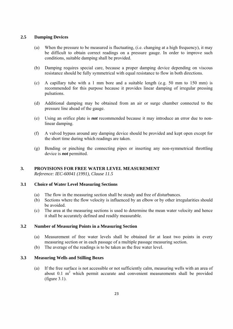
3.3 Measuring Wells and Stilling Boxes
(a) If the free surface is not accessible or not sufficiently calm, measuring wells with an area of
about 0.1 m2 which permit accurate and convenient measurements shall be provided (figure 3.1).

24
(b) All connections shall be normal to the wall of the measuring section and should preferably be covered with smooth perforated plates (perforations of 5 mm to 10 mm diameter).
(c) Such cover plates must be flush with the wall of the measuring section to criminate any local disturbances.
(d) The connection between the measuring section and well should have a passage area of at least 0.01 m2.
(e) The total area of perforation should be in the under of 25% of the passage area. (f) It is recommended that at least two measuring wells be provided at each measuring section
on opposite sides of the canal/channel.
Figure 3.1 – Details of measuring well Source: IEC-60041 (1991)
4. PROVISIONS FOR ABSOLUTE-DISCHARGE MEASUREMENT IN GENERAL
Reference: IEC-60041 (1991), Clauses 10.1, 10.1.1 and 15.1.3.
(a) The measurement of discharge in a hydroelectric or pumped storage plant can be performed with the desired accuracy only when the specific requirements of the chosen method are satisfied.
(b) It is desirable to select the method(s) to be used for the performance testing at an early
stage in the design of the plant because later provision may be expensive or even impracticable.
(c) The discharge measurement for the unit efficiency test shall be made by an absolute
method. (d) The absolute methods of discharge measurement recommended for use in the field are:
(i) Propeller current meters (ii) Pitot tube (iii) Pressure-time method (iv) Tracer methods (v) Weirs (vi) Standardized differential pressure devices. (vii) Volumetric gauging (viii) Ultrasonic (or acoustic) method

25
(e) It is recommended that provisions be made for two absolute methods of discharge measurement.
(f) The choice of the method (s) for measuring discharge may be affected by (i) Limitations imposed by the design of the plant; (ii) Cost of installation and special equipment; and (iii) Limitations imposed by the plant operating conditions. (g) It may be useful to resort to relative methods (index methods) of discharge measurement
either to gain supplementary information or to make some measurements easier. This becomes particularly important if the primary method used shows excessive uncertainties or falls out in a certain operating range.
5. PROVISIONS FOR ABSOLUTE-DISCHARGE MEASUREMENT BY CURRENT-METER METHOD Reference: IEC-60041 (1991), Clause 10.2
5.1 General Requirements
Reference: Clause 10.2.1 (a) The method may be used at a suitable measuring section in:
(i) A closed conduit or penstock (ii) An intake structure (iii) An upstream open channel (headrace) (iv) A downstream open channel (tailrace)
(b) A number of propeller current-meters (PCMs) should be located at specified points in a suitable cross-section of an open channel or closed conduit.
(c) Simultaneous measurements of local mean velocity with the meters should be integrated over the measuring section to obtain the discharge.
(d) The water should be sufficiently clean, such that dissolved or suspended matter will not affect the accuracy of the meter readings during the test.
(e) Integration techniques are used to compute the discharge assuming velocity distributions that closely approximate the known laws. Therefore, it is essential to select a measuring section that satisfies the following conditions: (i) If open channel, it should be an artificial channel with uniform and well defined
cross section and shall be straight for both upstream and downstream sides of the measuring section. Natural streams are excluded for tests under IEC Standard 60041.
(ii) If closed conduit, it should be nearly horizontal with smooth inner surface, uniform cross section and free from bends and discontinuities both upstream and downstream sides of the measuring section.

26
5.2 Number of Measuring Points Reference: Clause 10.2.2.2
(a) The number of current-meters should be sufficient to ensure a satisfactory determination of
the velocity profile over the whole measuring section. A single-point measurement is not permitted under IEC Standard 60041.
(b) If the conduit or channel is divided into several sections, measurements should be made simultaneously in all sections.
(c) In a circular penstock, at least 13 measuring points should be used one of which should be
the centre point of the section. The number of measuring points per radius, Z, excluding the centre point, may be determined from
�
where ‘R’ is the internal radius of the conduit in meters. For any given number of current-meters, it is preferable to increase the number of radii than to increase the number of current-meters per radius, but care must be taken to avoid excessive blocking. Centre blocking can be reduced by cantilevering the radial supporting arms from the conduit wall. If this is done, only a single arm need extend to the centre of the conduit. Measurements on more than 8 radii or at more than 8 points per radius, excluding the centre point, are not recommended.
(d) In a rectangular or trapezoidal section, at least 25 measuring points should be used. If the
velocity distribution is likely to be non-uniform, the number of measuring points, Z, should be determined from
33 3624 AZA where ‘A’ is the area of the measuring section in square metres.
5.3 Type and Size of Current Meters Reference: Clause 10.2.2.3
(a) Only propeller-type current meters should be used. (b) The current meters should fulfill the applicable requirements of ISO - 2537. (c) The propeller current meters shall be capable of withstanding the water pressure and the
time of submergence without charge in the calibration. (d) Current-meter propellers should be of diameter not less than 100 mm except for
measurement in the peripheral zone where propellers of diameter as small as 50 mm may be used.
(e) The distance from the trailing edge of the propeller to the leading edge of the mounting rod shall be at least 150 mm.
(f) The angle between the local velocity vector and the axis of the current-meter shall not exceed 50. When larger angles are unavoidable, self-compensating propellers which measure directly the axial component of the velocity, shall be used.

27
5.4 Provisions for Measurement in Short Penstocks and Intake Structures Reference: Clause 10.2.4
(a) A penstock is defined as short if the straight length is less than 25 diameters. (b) The main difficulty in measuring discharge in short penstocks and intake structures arises
from the fact that the measuring section may be located in a short converging conduit with uneven and/or unstable velocity distributions as well as oblique flow with respect to the current-meters.
(c) To remedy these difficulties in relation to the intake structure, a temporary bell-mouth nozzle (see figure 5.1) may be installed at the entrance to the intake structure achieving a straight and parallel flow. The flow through the modified intake may change the performance of the machine, but this change is negligible.
Figure 5.1 - Temporary nozzle or bell-mouth placed in the intake of a low-head turbine
Source: IEC-60041 (1991) 5.5 Provisions for Measurement in Open Channels
Reference: Clause 10.2.5
(a) The measuring section should have both width and depth greater than 0.80 m and at least eight times the diameter of the propeller.
(b) The measuring section should be at least ten times its hydraulic radius (which is defined as the ratio of the wetted cross-sectional area to the wetted perimeter).
(c) If necessary, the flow pattern at the measuring section may be improved by the installation of racks, rafts or submerged floor shown in figure 5.2. Some of these devices are effective in suppressing surface waves also, which increases the accuracy of the depth-measurement.

28
Figure 5.2 - Means for stabilizing flow in an open channel
Source: IEC-60041 (1991)
(d) There shall be a minimum of 25 measuring points located at the intersection of 5 horizontal and 5 vertical lines.
(e) Measuring points should be closer to one another in the zones of steeper velocity gradient, i.e. near the walls, bottom and water surface.
(f) Points should normally be spaced so that the difference in velocities between two adjacent points does not exceed 20% of the greater of the two velocities.
(g) The minimum current-meter spacing should not be less than (d + 30) mm, where ‘d’ is the outside diameter of the propeller in mm.
(h) The distance from the axis of the nearest current-meter to any wetted surface should be within 0.75d minimum to 200 mm maximum.
(i) The axis of the topmost current-meter in each row should be at least one propeller diameter below the free water surface.
(j) All current-meters should be rigidly attached to the mounting rods with the propeller axes exactly perpendicular to the plane of the measuring section.
(k) The stiffness of the mounting structures should be adequate to prevent current meter vibrations.
(l) The structure should also offer a minimum stable drag and minimum interference with the current-meter operation.
(m) The current-meters may be used as a stationary battery mounted on a number of parallel rods over the whole measuring section. Such an arrangement may produce a significant blockage effect in channels of small cross-section, and hence should not be used in small section channels.
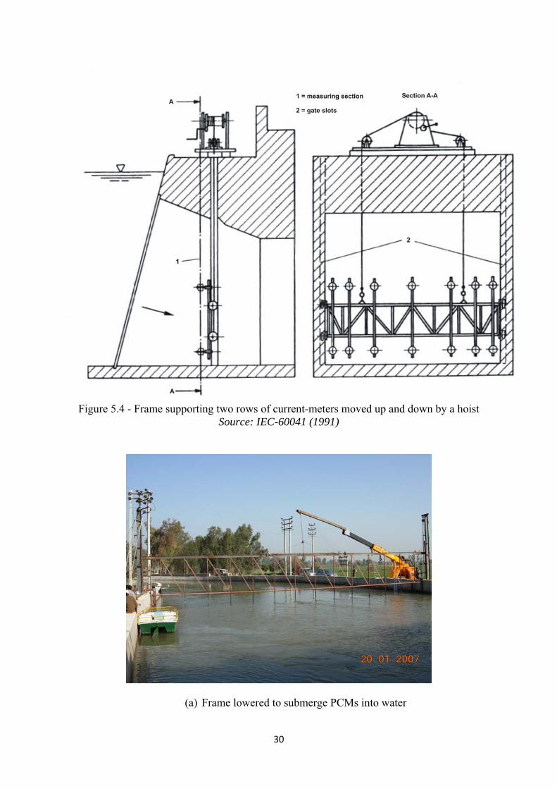
(n) As an alternative arrangement for mounting of current meters, a single vertical row of current meters mounted on a travelling winch (see figure 5.3) or one or two a horizontal rows of current meters mounted on a frame (see figures 5.4 and 5.5) may be moved to successive stations in the measuring cross-section. Since this requires steady flow over a considerable length of time, any variations in the mean velocity should be monitored over the whole run by at least one fixed current-meter or by an index measurement of discharge. The water depth should also be monitored over the whole duration of each runs; variations in water depth should not exceed ± 1% of the average value.

29
Figure 5.3 - Single vertical row of current-meters fixed on a travelling winch
Source: IEC-60041 (1991)
30
Figure 5.4 - Frame supporting two rows of current-meters moved up and down by a hoist
Source: IEC-60041 (1991)
(a) Frame lowered to submerge PCMs into water
31
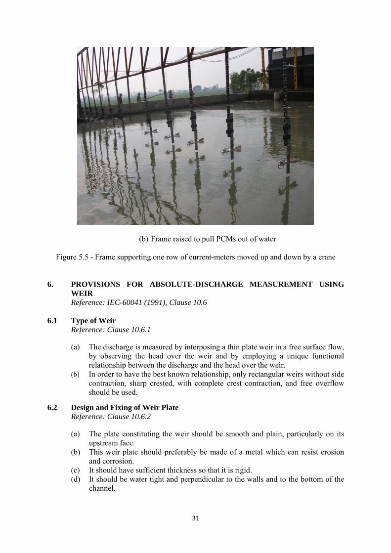
(b) Frame raised to pull PCMs out of water
Figure 5.5 - Frame supporting one row of current-meters moved up and down by a crane
6. PROVISIONS FOR ABSOLUTE-DISCHARGE MEASUREMENT USING
WEIR Reference: IEC-60041 (1991), Clause 10.6
6.1 Type of Weir
Reference: Clause 10.6.1 (a) The discharge is measured by interposing a thin plate weir in a free surface flow,
by observing the head over the weir and by employing a unique functional relationship between the discharge and the head over the weir.
(b) In order to have the best known relationship, only rectangular weirs without side contraction, sharp crested, with complete crest contraction, and free overflow should be used.
6.2 Design and Fixing of Weir Plate Reference: Clause 10.6.2 (a) The plate constituting the weir should be smooth and plain, particularly on its
upstream face. (b) This weir plate should preferably be made of a metal which can resist erosion
and corrosion. (c) It should have sufficient thickness so that it is rigid. (d) It should be water tight and perpendicular to the walls and to the bottom of the
channel.
32
(e) The surface of the weir crest should be a horizontal, flat and smooth and should be perpendicular to the upstream face of the plate.
(f) Intersection of the weir crest with the upstream face should be straight and form sharp edges, free from burrs or scratches.
(g) Its edge width perpendicular to the upstream face should be within 1 mm to 2 mm.
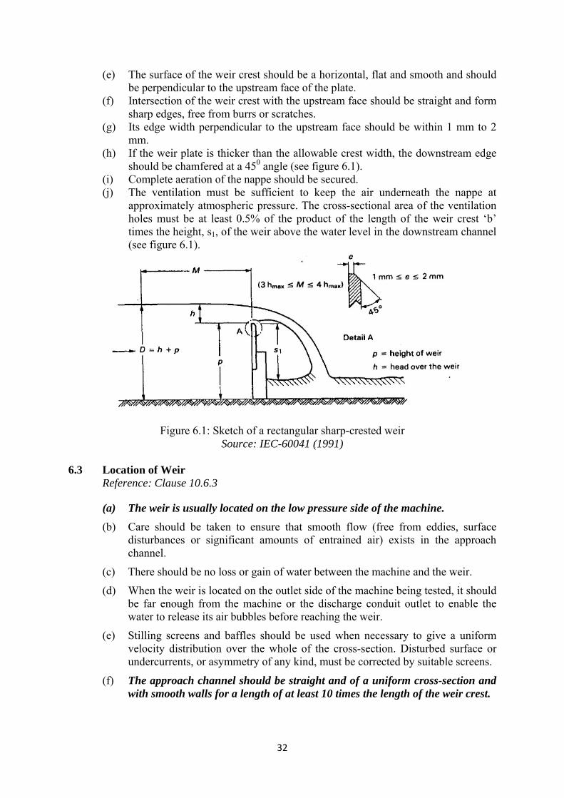
(h) If the weir plate is thicker than the allowable crest width, the downstream edge should be chamfered at a 450 angle (see figure 6.1).
(i) Complete aeration of the nappe should be secured. (j) The ventilation must be sufficient to keep the air underneath the nappe at
approximately atmospheric pressure. The cross-sectional area of the ventilation holes must be at least 0.5% of the product of the length of the weir crest ‘b’ times the height, s1, of the weir above the water level in the downstream channel (see figure 6.1).
Figure 6.1: Sketch of a rectangular sharp-crested weir Source: IEC-60041 (1991)
6.3 Location of Weir
Reference: Clause 10.6.3 (a) The weir is usually located on the low pressure side of the machine.
(b) Care should be taken to ensure that smooth flow (free from eddies, surface disturbances or significant amounts of entrained air) exists in the approach channel.
(c) There should be no loss or gain of water between the machine and the weir.
(d) When the weir is located on the outlet side of the machine being tested, it should be far enough from the machine or the discharge conduit outlet to enable the water to release its air bubbles before reaching the weir.
(e) Stilling screens and baffles should be used when necessary to give a uniform velocity distribution over the whole of the cross-section. Disturbed surface or undercurrents, or asymmetry of any kind, must be corrected by suitable screens.
(f) The approach channel should be straight and of a uniform cross-section and with smooth walls for a length of at least 10 times the length of the weir crest.

33
(g) If stilling screens or baffles are used, they should be located at distance upstream of the weir greater than this length.
(h) Along this length, the bottom slope must be small (< 0.005).
(i) A desilting sluice can be installed if required, but it should not disturb the regular flow of water along the upstream face of the weir.
(j) The sides of the channel above the level of the crest of weir should extend without discontinuity at least 0.3 hmax downstream of the plane of the weir.
6.4 Measurement of Head Over Weir
Reference: Clause 10.6.4 (a) It should be easily possible to measure the head over weir ‘h’ upstream of the
weir at a distance ‘M’ which shall be between three and four times the maximum head (see figure 6.1).
(b) It should be easily possible to measure at a number of measuring points uniformly spaced across the weir channel.
(c) The number of measuring points shall be as follows :
Length of crest ‘b’
Number of measuring points
b < 2m 2m ≤ ��b ≤ 6 m
b > 6m
2 3 4 or more
(d) However this number may be reduced to a minimum of 2, where approach
velocities are small and the velocity distribution is particularly regular. (e) Measurements of the head at each point of measurement should not differ by
more than 0.5%. If they do, every endeavour should be made to this requirement by installing screens, baffles or rafts. The arithmetic mean of all the head measurements should be used for computing the discharge.
(f) The head measurement devices should be placed in stilling wells at the sides of the approach channel, communicating through special pressure connections terminating in taps that are flush with the channel wall, 3 mm to 6 mm in diameter and at least twice the diameter in length.
(g) The water in the stilling well should be purged from time to time to ensure that its temperature is within ± 20C of that in the approach channel.
6.5 Discharge Formulae
Reference: Clauses 10.6.1, 10.6.5 and 10.6.6 (a) The basic formula for calculating the discharge (due to Poleni) is :
where Q is the discharge

34
C is the discharge coefficient b is the length of the weir crest (perpendicular to the flow) g is the acceleration due to gravity h is the measured upstream head over the weir
(b) The accuracy of discharge measurements made with a rectangular thin-plate
weir depends on the accuracy of the head and crest length measurements and on the accuracy of the discharge coefficient used. It is therefore desirable that, whenever possible, the weir should be calibrated under the existing conditions of installation and use.
(c) If such a calibration is not carried out and no mutual agreement has been made by the parties for using one of the experimental formulae, the discharge should be computed by the following average formula :
The following dimensional restrictions apply: b ≥ �0. 40 m p ≥ 0. 30 m
0.06 m ≤ h ≤ ��0. 80 m 0.15 ≤ h/p ≤ 1. 00
Where p is the height of weir relative to the floor.
(d) The use of the limiting value of more than one of the parameters given above at the same time should be avoided.
7. PROVISIONS FOR ABSOLUTE-DISCHARGE MEASUREMENT BY ULTRASONIC (ACOUSTIC) METHODS Reference: IEC – 60041 (1991), Appendix J
7.1 General
At the time the IEC Standard 60041 was issued, experience with the ultrasonic (acoustic) methods of discharge measurement was limited. So their application in evaluating the efficiency of generating units by this standard is permitted by mutual agreement or in conjunction with an established method of discharge measurement. Since then, however, a large number of instruments based on ultrasonic methods of discharge measurement have been developed and are widely used in several applications. The long experience of turbine testing groups world over, including the IIT Roorkee Test Team, with different ultrasonic methods and instruments of discharge measurement has been extremely good. Ultrasonic methods are now recognized as versatile and reliable methods of absolute-discharge measurement for efficiency evaluation of generating units. The following ultrasonic discharge measuring methods/instruments, based on two different principles, namely the
35
transits-time and the Doppler effect, are now being used by the IIT Roorkee Test Team: (a) Intrusion or wet-transducer ultrasonic transit-time flowmeter (WT - UTTF) (b) Clamp-on or dry-transducer ultrasonic transit-time flowmeter (DT - UTTF) (c) Horizontal-beam acoustic doppler current profiler (H - ADCP) (d) Vertical-beam acoustic doppler current profiler (V - ADCP)
The method at (a) above is suitable for both steel-pipe penstocks, ducts and open
channels, the method at (b) for steel-pipe penstocks only and the method at (c) for open channels. The method at (d) can be used in irregular-section channels, where most other methods of discharge measurement may be impracticable.
The intrusion or wet-transducer UTTF is the only ultrasonic method/instrument
included in IEC-60041 and its use is described only with closed conduits. It has a very high accuracy potential, if applied properly and the site conditions are good. The clamp-on or dry-transducer type UTTF also can give a good accuracy under favourable conditions, while it is much cheaper and lot easier and faster to use as compared to its wet-transducer counterpart. The uncertainty of discharge measurement with dry-transducer UTTF in new SHP stations, based on the experience of the IIT Roorkee Test Team, ranges from 1.5-2.5%, against 1-2% for the wet-transducer UTTF as suggested in IEC-60041. The DT-UTTF also compares favourably in this regard with all other methods of discharge measurement. The WT-UTTF requires drilling of several holes in the penstock and hence not favoured by power station owners.
The requirements and provisions for discharge measurement with WT-UTTF in
penstocks as per IEC-60041, are described below. The requirements of discharge measurement with WT-UTTF in open channels, with DT-UTTF in conduits and with ADCPs in open channels, given in the following sections, are based on the same basic principles as well as on the experience of the IIT Roorkee Test Team.
7.2 Provisions for Discharge Measurement with WT-UTTF in Penstock
(a) The transducers acting as the transmitter and receiver should be fixed in the conduit in such a way that signals are transmitted upstream and downstream at an angle �relative to the axis of the conduit (see figure 7.1). The value of �� should be between 450 and 750. Therefore, necessary length of the penstock should be left un-embedded (exposed) at the time of construction to allow drilling of holes for transducers and fixing them.

36
Figure 7.1 – Principle of discharge measurement with UTTF
Source: IEC-60041 (1991)
(b) In order to reduce the systematic uncertainty due to effects of transverse flow components, two acoustic planes A and B as shown in figure 7.2 should be used.
(c) If the velocity distribution were fully axi-symmetric, the average velocity measured along a single path located in an axial-plane could be assumed proportional to the mean flow velocity in the conduit. To take into account the actual velocity distribution in practice it is necessary to install several pairs of transducers at opposite ends of a number of paths located in the measurement planes at angle �� to the longitudinal axis of the conduit and distributed symmetrically about this axis , as shown in figure 7.2.
Figure 7.2 –Typical arrangement of transducers in a circular conduit Source: IEC-60041 (1991)
37
(d) The measuring section should be chosen as far as possible from any upstream disturbance, such as a bend, that could create asymmetry of the velocity distribution, swirl or large scale turbulence. Other factors that may produce transverse velocity components or distortion of the velocity profile are the flow conditions upstream of the intake, the shape of the intake, the number of bends upstream of the measuring section, changes in upstream conduit diameter and the proximity of bends or changes in conduit diameter downstream.
(e) Measurement of discharge using a single path in one or two measuring planes is not permitted by the Standard.
(f) If two acoustic planes with four paths each are used, then there should be a straight length of upstream conduit between the measuring section and any important irregularity of at least ten conduit diameters. Similarly, there should be a straight length of at least three conduit diameters between the measuring section and any important downstream irregularity.
(g) A single acoustic plane with four paths located downstream of a straight length of twenty conduit diameters or more, providing a uniform flow distribution in the measuring section, is also acceptable.
(h) It should be possible to empty the penstock to allow laying out of transducer locations, drilling of holes in the penstock, fixing the transducers and aligning them. (Although this process can be carried out in hot condition, that is, without stopping water flow in the penstock, the techniques used are very difficult and expensive).
(i) Flow velocity and diameter of the conduit shall be large enough to permit an accurate determination of the difference in acoustic pulse transit times taking into account the accuracy of the timer. Measurements with flow velocities less than 1.5 m/s and diameters of conduits less than 0.8 m should be avoided.
(j) Bubbles, sediment and acoustic noise may disrupt the operation of the acoustic flow measurement system and a measuring section involving any of them should be avoided.
(k) The layout of transducer locations and measurement of as-built dimensions must be done using accurate methods. For large conduits surveying techniques and for smaller conduits careful shop measurements can be used. In either case, the uncertainties of the as-built measurements must be accounted for in the error analysis.
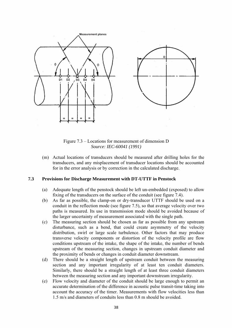
(l) Special care should be taken for conduits that do not have perfectly circular shape. A representative dimension D should be determined in the measuring section. At least five equally spaced measurements of D should be taken, including one at the centre of the measuring section and one at each end as illustrated in figure 7.3. These measurements should be averaged to be representative of the conduit dimension in the measuring section.
38
Figure 7.3 – Locations for measurement of dimension D Source: IEC-60041 (1991)
(m) Actual locations of transducers should be measured after drilling holes for the
transducers, and any misplacement of transducer locations should be accounted for in the error analysis or by correction in the calculated discharge.
7.3 Provisions for Discharge Measurement with DT-UTTF in Penstock
(a) Adequate length of the penstock should be left un-embedded (exposed) to allow fixing of the transducers on the surface of the conduit (see figure 7.4).
(b) As far as possible, the clamp-on or dry-transducer UTTF should be used on a conduit in the reflection mode (see figure 7.5), so that average velocity over two paths is measured. Its use in transmission mode should be avoided because of the larger uncertainty of measurement associated with the single path.
(c) The measuring section should be chosen as far as possible from any upstream disturbance, such as a bend, that could create asymmetry of the velocity distribution, swirl or large scale turbulence. Other factors that may produce transverse velocity components or distortion of the velocity profile are flow conditions upstream of the intake, the shape of the intake, the number of bends upstream of the measuring section, changes in upstream conduit diameter and the proximity of bends or changes in conduit diameter downstream.
(d) There should be a straight length of upstream conduit between the measuring section and any important irregularity of at least ten conduit diameters. Similarly, there should be a straight length of at least three conduit diameters between the measuring section and any important downstream irregularity.
(e) Flow velocity and diameter of the conduit should be large enough to permit an accurate determination of the difference in acoustic pulse transit-time taking into account the accuracy of the timer. Measurements with flow velocities less than 1.5 m/s and diameters of conduits less than 0.8 m should be avoided.

39
(f) Bubbles, sediment and acoustic noise may disrupt the operation of the acoustic flow measurement system and measuring section involving any of them should be avoided.
(g) Special care should be taken for conduits that do not have perfectly circular shape. A representative dimension D should be determined in the measuring section. At least five equally spaced measurements of D shall be taken, including one at the centre of the measuring section and one at each end (see figure 7.3). These measurements shall be averaged to be representative of the conduit dimension in the measuring section.
(h) The surface of the penstock should be properly prepared for clamping the transducers on to it. No trace of paint or rust should be left and the surface should be made smooth and clean so as to ensure a good contact between the conduit surface and the transducer face.
Figure 7.4 – Adequate lengths of penstocks left un-embedded
Figure 7.5 – Transducers of the UTTF clamped on a penstock in reflection mode
40
7.4 Provisions for Discharge Measurement with WT-UTTF in Open Channel
(a) The measuring section of the open channel should be chosen as far as possible from any upstream disturbance, such as a bend in the channel that could create asymmetry of the velocity distribution across the width of the channel, swirl, or large scales turbulence.
(b) The channel cross-section both upstream and downstream of section should be uniform, as a change in cross-section may produce transverse velocity components and distortion of the velocity profile.
(c) There should be a straight length of the upstream channel, between the measuring section and any important irregularity, of at least ten times the channel width. Similarly, there should be a straight length of at least three times the channel width between the measuring section and any important downstream irregularity.
(d) A representative value of the channel width shall be determined in the measuring section. Measurements shall be made at least at three cross-sections: one at the centre of the measuring section and one at each end. At each of these cross-sections, width shall be measured in each horizontal plane of the transducers. These measurements shall be averaged to be representative of the width in the measuring section.
(e) It should be possible to empty the channel at the measuring section to allow fixing of the transducers on its walls and their alignment.
7.5 Provisions for Discharge Measurement with H-ADCP in Open Channel
(a) The measuring section of the open channel should be chosen as far as possible from any upstream disturbance, such as a bend in the channel, that could create asymmetry of the velocity distribution across the width of the channel, swirl, or large scales turbulence.
(b) The channel cross-section both upstream and downstream of section should be uniform, as a change in cross-section may produce transverse velocity components and distortion of the velocity profile.
(c) There should be a straight length of the upstream channel, between the measuring section and any important irregularity, of at least ten times of the channel width. Similarly, there should be a straight length of at least three times the channel width between the measuring section and any important downstream irregularity.
(d) A representative value of the channel width should be determined in the measuring section. Several measurements of the channel width will be taken at various depths as far as possible, which will be then averaged to be representative of the channel width at the measuring section.
(e) A guide-rail should be rigidly fixed in vertical plane to one of abutments of the channel for the H-ADCP trolley to move in water along the rail in the measuring section (see figures 7.6 and 7.7).
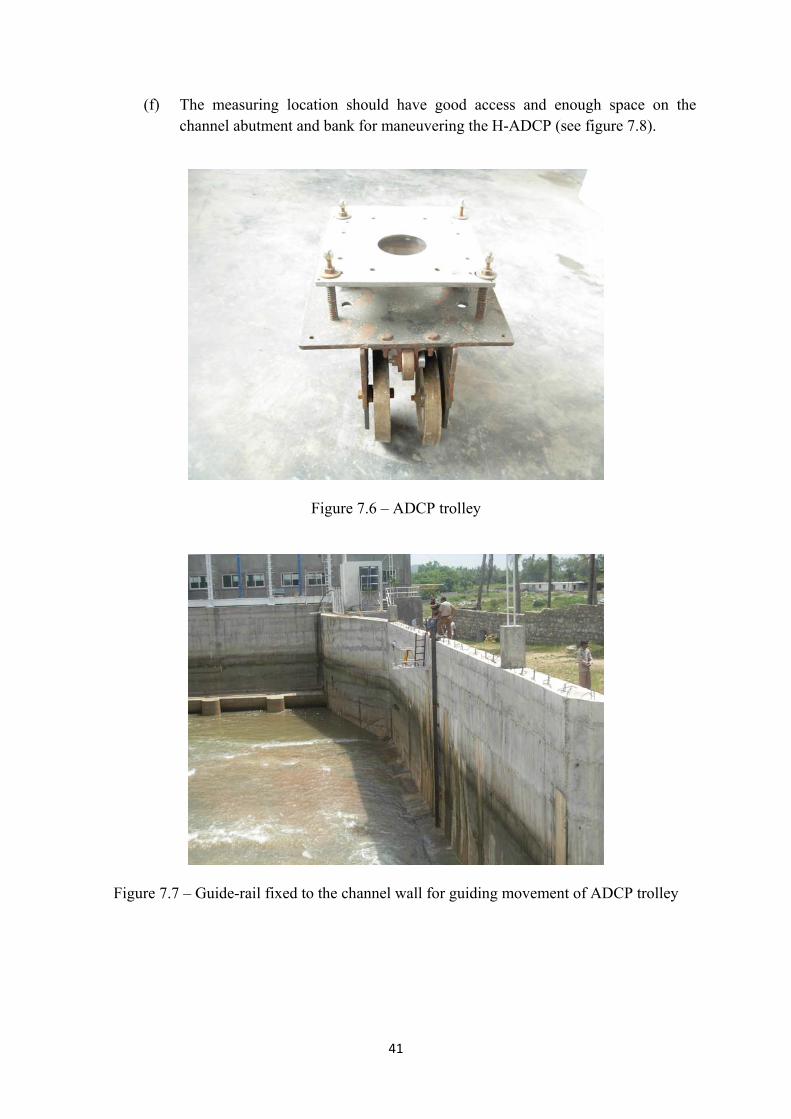
41
(f) The measuring location should have good access and enough space on the channel abutment and bank for maneuvering the H-ADCP (see figure 7.8).
Figure 7.6 – ADCP trolley
Figure 7.7 – Guide-rail fixed to the channel wall for guiding movement of ADCP trolley

42
Figure 7.8 – Maneuvering ADCP trolley movement on the guide-rail
7.6 Provision for Discharge Measurement with V-ADCP in Open Channel
(a) The measuring section of the open channel should be chosen as far as possible from any upstream disturbance, such as a bend in the channel, that could create swirl or large scales turbulence.
(b) There should be a straight length of the upstream channel, between the measuring section and any important irregularity, of at least ten times of the channel width. Similarly, there should be a straight length of at least three times the channel width between the measuring section and any important downstream irregularity.
(c) The measuring location should have good access and enough space on both the abutments and banks of the channel for maneuvering the V-ADCP (see figure 7.9).

43
Figure 7.9 – Maneuvering V-ADCP from channel banks
8. PROVISIONS FOR RELATIVE-DISCHARGE MEASUREMENT Reference: IEC-60041(1991), Clause 15.2 The Index Test involves measurement of relative-discharge as opposed to the measurement of absolute-discharge required for unit efficiency test. The index test is highly recommended as it can give some of the following very useful information: (i) To determine the relative variation in the unit efficiency with load or gate/valve
opening. (ii) To determine the correct relationship between runner blade angle and guide
vane opening in the case of a double regulated machine. (iii) To provide additional test data during the unit efficiency test.
The methods used for measuring the relative discharge are the secondary methods. The following methods are recommended in the IEC Standard 60041:
(i) Measurement of pressure difference between suitably located taps on the turbine
spiral case (Winter-Kennedy method). (ii) Measurement of pressure difference between suitably located taps in tubular
turbines. (iii) Measurement of pressure difference between suitably located taps on a bend or
taper section of the penstock. (iv) Single-path ultrasonic transit-time flowmeter. (v) Measurement of needle stroke on pelton turbines. (vi) Measurement by means of a single current meter.
Therefore, it is highly desirable that necessary provisions are made for the measurement of relative discharge, as explained /illustrated below:

44
8.1 Provision of Pressure Taps in Spiral Case of Turbine Reference: Clause 15.2.1.1
(a) In installations with a steel spiral case, the relative discharge can be best measured by the Winter- Kennedy method, which consists in providing a pair of pressure taps on the spiral case appropriately and measuring the differential pressure ‘Δp’ between the taps using an electronic differential pressure gauge.
(b) The relation between the discharge ‘Q’ and ‘Δp’ is well represented by
Q= k (Δp) n
where ‘n’ is theoretically equal to 0.5. (c) The pair of pressure taps should be located in the same radial section of the spiral
case, as shown in figure 8.1 and illustrated by a photograph in figure 8.2.
Figure 8.1 – Location of pressure taps in steel spiral case
Source: IEC-60041 (1991)

45
Figure 8.2 – Illustration of pressure taps in vertical steel spiral case (d) The outer tap ‘1’ is located at the outer side of the spiral. The inner tap ‘2’ should
be located outside of the stay vanes on a flow line passing midway between the two adjacent stay vanes.
(e) It is recommended that a second pair of taps be similarly located in another radial section.
(f) With a horizontal spiral case, the taps should be arranged in the upper half because of the better possibility of purging.
(g) The pressure taps should not be in proximity to welded joints or abrupt changes in the spiral section.
(h) The pressure taps should comply with the requirements described in section 2.3 and illustrated in figure 2.1. Since the differential pressures to be measured may be small, special attention should be given to removing surface irregularities.
8.2 Provision of Pressure Taps in Semi-Spiral Case of Turbine
Reference: Clause 15.2.1.1
(a) The Winter-Kennedy method (see section 8.1) is the best method of relative discharge measurement even for turbines with a concrete semi-spiral case.
(b) The pressure taps should be located in a radial section of the concrete case as shown in figure 8.3.
(c) It is recommended that two pairs of taps should be provided. (d) The outer tap 1 (or 1´) should be located sufficiently far from the corners. The
inner tap 2 (or 2´) should be located outside of the stay vanes on a flow line passing midway between two adjacent stay vanes. A third tap 3 may be arranged on a stay vane, preferable at the elevation of the centre-line of the guide vanes, or on the roof between two stay vanes.
(e) The pressure taps should comply with the requirements described in section 2.3 and illustrated in figure 2.1. Since the differential pressures to be measured may be small, special attention should be given to removing surface irregularities.

46
(f) The pipes connecting the taps to the differential pressure gauge should slope upward to the gauge with no intermediate high spots where air may be trapped. Valves should be provided at high points for purging (flushing out air). See figure 8.4.
Figure 8.3 – Location of pressure taps in concrete semi-spiral case
Source: IEC-60041 (1991)

47
Figure 8.4 – Upward sloping pipes and valves for purging 8.3 Provision of Pressure Taps in Tubular Turbines
Reference: Clause 15.2.1.3
(a) In application of the differential pressure method of measuring relative discharge through a bulb turbine, the taps may be located as shown in figure 8.5.
(b) It is recommended that two pairs of pressure taps should be provided. (c) The tap for higher pressure may be arranged at the stagnation point of the bulb
(point 1) or of the access shaft (point 1´) and tap for lower pressure should be located on the wall directly upstream from the guide vanes, however with sufficient distance from their profile nose at maximum guide vane opening (point 2 or 2´).
(d) Discharge may be assumed proportional to the square root of the differential pressure.
(e) For all other types of tubular turbines (e.g. pit turbine) analogous application may be made.
(f) The pressure taps used should comply with the requirements described in section 2.3 and illustrated in figure 2.1. Since the differential pressures to be measured may be small, special attention should be given to removing surface irregularities.
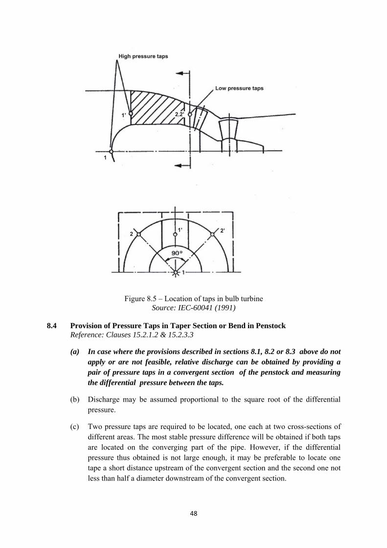
48
Figure 8.5 – Location of taps in bulb turbine
Source: IEC-60041 (1991) 8.4 Provision of Pressure Taps in Taper Section or Bend in Penstock
Reference: Clauses 15.2.1.2 & 15.2.3.3
(a) In case where the provisions described in sections 8.1, 8.2 or 8.3 above do not apply or are not feasible, relative discharge can be obtained by providing a pair of pressure taps in a convergent section of the penstock and measuring the differential pressure between the taps.
(b) Discharge may be assumed proportional to the square root of the differential pressure.
(c) Two pressure taps are required to be located, one each at two cross-sections of different areas. The most stable pressure difference will be obtained if both taps are located on the converging part of the pipe. However, if the differential pressure thus obtained is not large enough, it may be preferable to locate one tape a short distance upstream of the convergent section and the second one not less than half a diameter downstream of the convergent section.
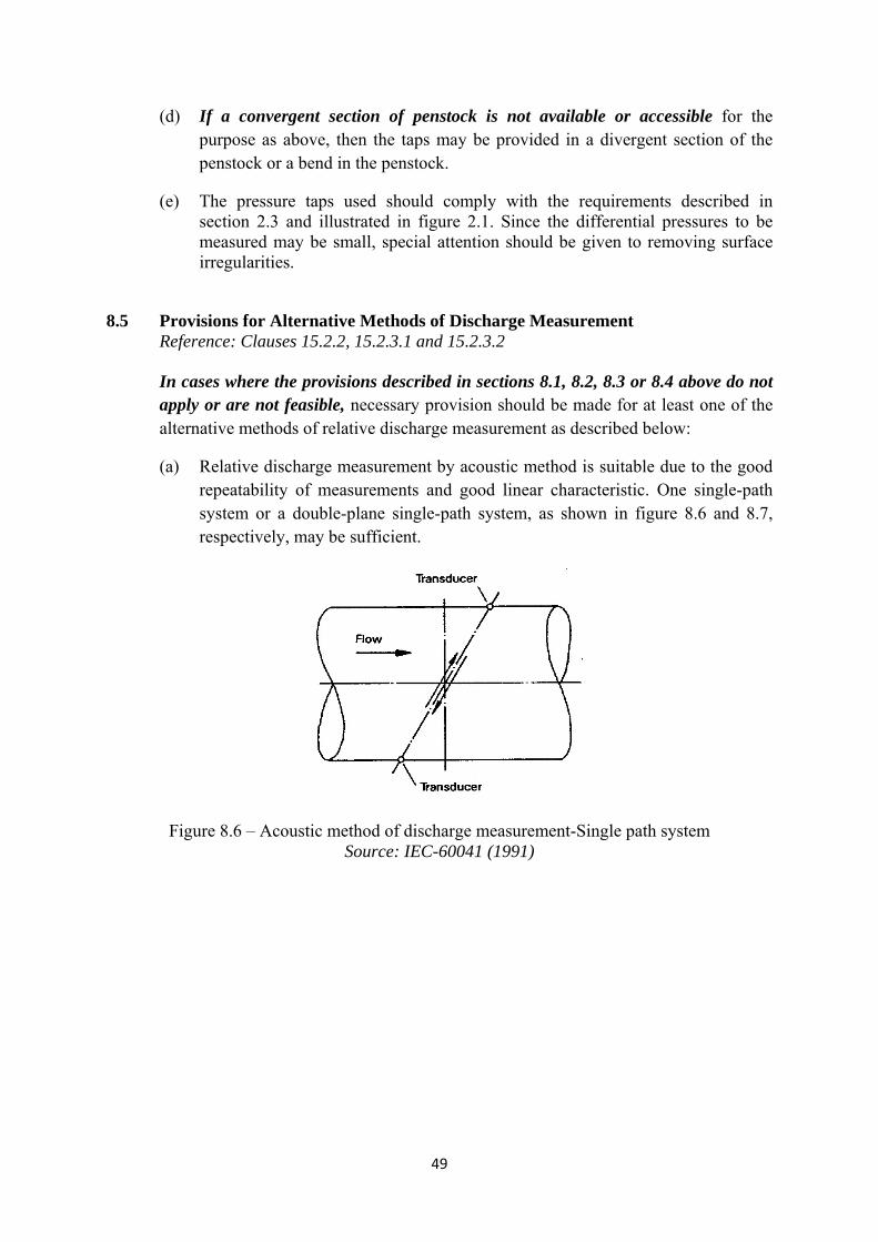
49
(d) If a convergent section of penstock is not available or accessible for the purpose as above, then the taps may be provided in a divergent section of the penstock or a bend in the penstock.
(e) The pressure taps used should comply with the requirements described in section 2.3 and illustrated in figure 2.1. Since the differential pressures to be measured may be small, special attention should be given to removing surface irregularities.
8.5 Provisions for Alternative Methods of Discharge Measurement Reference: Clauses 15.2.2, 15.2.3.1 and 15.2.3.2
In cases where the provisions described in sections 8.1, 8.2, 8.3 or 8.4 above do not apply or are not feasible, necessary provision should be made for at least one of the alternative methods of relative discharge measurement as described below:
(a) Relative discharge measurement by acoustic method is suitable due to the good repeatability of measurements and good linear characteristic. One single-path system or a double-plane single-path system, as shown in figure 8.6 and 8.7, respectively, may be sufficient.
Figure 8.6 – Acoustic method of discharge measurement-Single path system
Source: IEC-60041 (1991)

50
Figure 8.7 – Acoustic method of discharge measurement-Double plane single-path system
Source: IEC-60041 (1991)
(b) The stroke of the needle of a Pelton turbine may be used to give relative discharge, provided that the discharge/stroke characteristic shape has been checked by tests on a homologous model of the turbine. Great care should be taken to ensure that during the test the needle, nozzle and support vanes are clean and in good order.
(c) Relative discharge can also be measured using one single current meter suitably located in the open channel or conduit, as the case may be.
9. PROVISIONS FOR ELECTRICAL POWER MEASUREMENT Reference: IEC-60041(1991), Clause 12
Electrical power output of generator is required to be measured as one of the parameters, both in the efficiency test and the maximum power output test. Certain provisions are recommended below to facilitate this measurement and to achieve good accuracy. The same provisions also facilitate error checks on panel meters.
9.1 Test Terminal Block
(a) A test terminal block (TTB), which is an inexpensive and standard control-panel accessory (see figure 9.1), should be provided on every metering panel.
(b) The TTB should be provided on the front, usually near the bottom, of the control panel (see figure 9.2).
(c) The TTB shall be appropriately wired to make available the current transformer (CT) and voltage transformer (VT) outputs on it. This will enable connecting a reference meter during testing from outside, without opening the panel or stopping the machine or switching off the machine breaker (see figure 9.3).
(d) The TTB should be of 3-phase 3-wire or of 3-phase 4-wire type, depending on the nature of the machine output.

51
(e) Locating the TTB inside a control panel should be avoided, because in that case a reference meter can be connected at the TTB only after opening the panel and working inside the live panel, which can be a safety hazard.
(f) It should be noted that sliding-link terminals, used as a standard practice to terminate CT outputs inside control panels, are not a substitute for the TTB on the front of the control panels, because a reference meter can be connected at the sliding-link terminals only after opening the panel and working inside the live panel, which can again be a safety hazard.
Figure 9.1 – A Sample TTB
Figure 9.2 – TTB (shown with cover in place) fitted on the front of a control panel
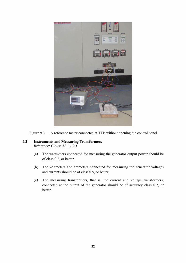
52
Figure 9.3 – A reference meter connected at TTB without opening the control panel
9.2 Instruments and Measuring Transformers Reference: Clause 12.1.1.2.1
(a) The wattmeters connected for measuring the generator output power should be of class 0.2, or better.
(b) The voltmeters and ammeters connected for measuring the generator voltages and currents should be of class 0.5, or better.
(c) The measuring transformers, that is, the current and voltage transformers, connected at the output of the generator should be of accuracy class 0.2, or better.
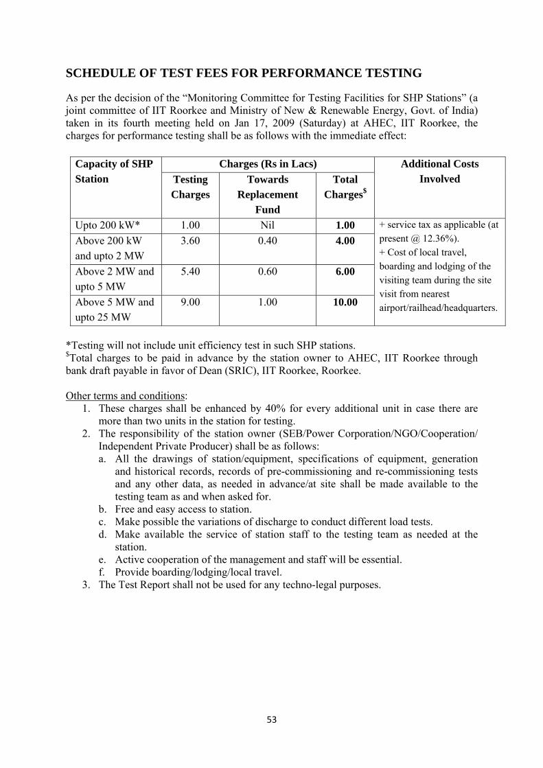
53
SCHEDULE OF TEST FEES FOR PERFORMANCE TESTING
As per the decision of the “Monitoring Committee for Testing Facilities for SHP Stations” (a joint committee of IIT Roorkee and Ministry of New & Renewable Energy, Govt. of India) taken in its fourth meeting held on Jan 17, 2009 (Saturday) at AHEC, IIT Roorkee, the charges for performance testing shall be as follows with the immediate effect:
Capacity of SHP Station
Charges (Rs in Lacs) Additional Costs Involved Testing
Charges Towards
Replacement Fund
Total Charges$
Upto 200 kW* 1.00 Nil 1.00 + service tax as applicable (at present @ 12.36%). + Cost of local travel, boarding and lodging of the visiting team during the site visit from nearest airport/railhead/headquarters.
Above 200 kW and upto 2 MW
3.60 0.40 4.00
Above 2 MW and upto 5 MW
5.40 0.60 6.00
Above 5 MW and upto 25 MW
9.00 1.00 10.00
*Testing will not include unit efficiency test in such SHP stations. $Total charges to be paid in advance by the station owner to AHEC, IIT Roorkee through bank draft payable in favor of Dean (SRIC), IIT Roorkee, Roorkee. Other terms and conditions:
1. These charges shall be enhanced by 40% for every additional unit in case there are more than two units in the station for testing.
2. The responsibility of the station owner (SEB/Power Corporation/NGO/Cooperation/ Independent Private Producer) shall be as follows: a. All the drawings of station/equipment, specifications of equipment, generation
and historical records, records of pre-commissioning and re-commissioning tests and any other data, as needed in advance/at site shall be made available to the testing team as and when asked for.
b. Free and easy access to station. c. Make possible the variations of discharge to conduct different load tests. d. Make available the service of station staff to the testing team as needed at the
station. e. Active cooperation of the management and staff will be essential. f. Provide boarding/lodging/local travel.
3. The Test Report shall not be used for any techno-legal purposes.

54
NETWORKING INSTITUTIONS AND TEAMS
AHEC, IITRoorkee (UK) 1. Dr H.K. Verma, Prof. of Electrical Engg. and Dy. Director, IIT Roorkee, Team Leader 2. Dr Arun Kumar, Head, AHEC and Coordinator Jadavpur University, Kolkata (WB) 1. Dr. B. Majumdar, Professor, Team Leader 2. Dr. Niledhi Chakroborty, Dy. Team Leader Maulana Azad National Institute of Technology, Bhopal (MP) 1. Dr Saroj Ragnekar, Professor, Team Leader 2. Dr Vishnu Prashad, Dy. Team Leader B R Ambedkar National Institute of Technology, Jalandhar (Punjab) 1. Dr Dilbag Singh, Team Leader 2. Dr R K Garg, Dy. Team Leader

55
SHP STATIONS TESTED The figure below shows the locations and tables 1 to 4 give the salient particulars of the 45 SHP stations tested upto 15th September 2009 by IIT Roorkee. These power stations are spread over 9 states of India: Andhra Pradesh (1), Punjab (7), Himachal Pradesh (13), Karnataka (16), Madhya Pradesh (1), Kerala (1), Uttarakhand (3), Mizoram (2) and Chhattisgarh (1).
Locations of the SHP stations tested

56
Table 1: Salient Particulars of SHP Stations Tested by IIT Roorkee (1-10) S. No.
Name of Station,District, State
Project Type, Capacity ( MW )
Longitude/ Latitude
Alt. (m)
Turbine type/ shaft, Manufacturer
Rated head (m)/ Rated discharge (m3/s)
Gear box/ Fly wheel
Generator type / Manufacturer
Governor type
Excitation, AVR
Testing completed in
1. Madhavaram,
Kurnool, AP Canal-fall based, 2x2
78030'0" 15041'10"
244 Kaplan/Ver, Boving Fouress
6.88/34 Yes/Yes Synchronous / WEG
PLC Brushless, Digital Electronic
Dec. 2004
2. Babbanpur, Sangrur, Punjab
Canal-fall based, 2x0.5
75054'36" 25048'0"
242 Semi Kaplan/ Ver, HPP
2.4 / 26 Yes/No Induction/ Kirloskar
Digital Electronic
Not Applicable
March 2005
3. Manal,
Sirmour, HP Run of river, 2x1.5
77036'45" 30035'35"
608 Pelton/Hor, Boving Fouress
201/0.88 No/Yes Synchronous / Marelli Motori
Digital Electronic
Brushless, Digital Electronic
Sep. 2005
4. Ching,
Shimla, HP Run of river, 2x0.5
77044'0" 3002'0"
1450 Pelton/Hor, HPP
145/0.43 No/Yes Synchronous/ Marelli Motori
Digital Electronic
Brushless, Analog Electronic
Sep. 2005
5. Aleo Manali,
Kullu, HP Run of river, 2x1.5
77011'52" 32014'0"
1850 Pelton/Hor, VA Tech
290/0.63 No/Yes Synchronous / WEG
Digital Electronic
Brushless, Digital Electronic
Nov. 2005
6. TB Dam,
Bellary, Karnataka
Dam-toe based, 3x2.65
76020'10" 15015'19"
480 Kaplan/Hor, Boving Fouress
10/31.2 Yes/Yes Synchronous / WEG
Digital Electronic
Brushless, Digital Electronic
Dec. 2005
7. Someshwara,
Mandya, Karnataka
Run of river, 3x8.25
77045'0" 16018'0"
452 Kaplan/ Ver, Boving Fouress
17.5/56 No/No Synchronous/ UCM Recita
PLC Brushless, Digital Electronic
Dec. 2005
8. Mandagere,
Mandya, Karnataka
Canal-fall based, 2x1.75
76022'30" 12044'0"
793 Kaplan/Hor, Alstom
6.8/30.86 Yes/Yes Synchronous / Crompton Greaves
Digital Electronic
Brushless, Analog Electronic
Feb. 2006
9. Chunchi Doddi, Bangalore, Karnataka
Run of river, 3x3.5
77027'0" 12012'0"
455 Francis/Hor, Boving Fouress
96/4.1 No/Yes Synchronous/ Kirloskar
PLC Brushless, Digital Electronic
Feb. 2006
10. Sugur,
Bellary, Karnataka
Run of river, 3x1.5
76045'55" 15029'27"
378 Kaplan/Ver, HPP
7.5/32.2 Yes/No Synchronous / Jyoti
PLC Brushless, Analog Electronic
March 2006
Abbreviations: AP – Andhra Pradesh, HP – Himachal Pradesh, MP – Madhya Pradesh
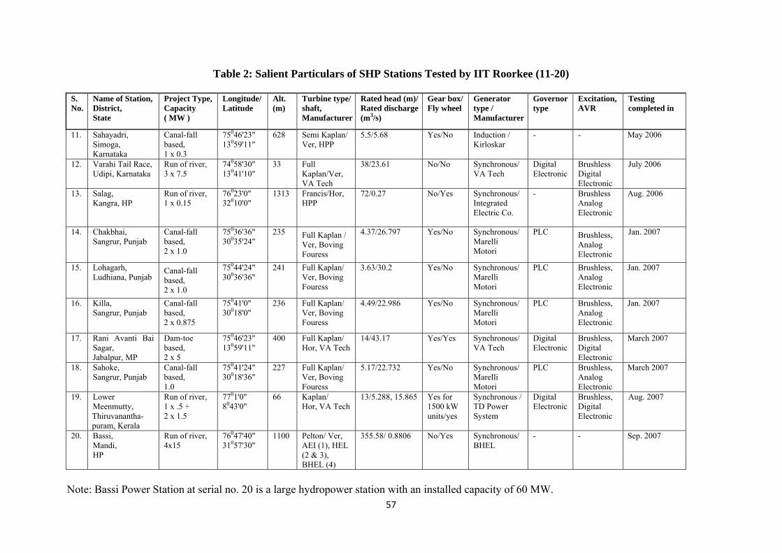
57
Table 2: Salient Particulars of SHP Stations Tested by IIT Roorkee (11-20)
S. No.
Name of Station, District, State
Project Type, Capacity ( MW )
Longitude/ Latitude
Alt. (m)
Turbine type/ shaft, Manufacturer
Rated head (m)/ Rated discharge (m3/s)
Gear box/ Fly wheel
Generator type / Manufacturer
Governor type
Excitation, AVR
Testing completed in
11. Sahayadri,
Simoga, Karnataka
Canal-fall based, 1 x 0.3
75046'23" 13059'11"
628 Semi Kaplan/ Ver, HPP
5.5/5.68 Yes/No Induction / Kirloskar
- - May 2006
12. Varahi Tail Race, Udipi, Karnataka
Run of river, 3 x 7.5
74058'30" 13041'10"
33 Full Kaplan/Ver, VA Tech
38/23.61 No/No Synchronous/ VA Tech
Digital Electronic
Brushless Digital Electronic
July 2006
13. Salag, Kangra, HP
Run of river, 1 x 0.15
76023'0" 32010'0"
1313 Francis/Hor, HPP
72/0.27 No/Yes Synchronous/ Integrated Electric Co.
- Brushless Analog Electronic
Aug. 2006
14. Chakbhai,
Sangrur, Punjab Canal-fall based, 2 x 1.0
75036'36" 30035'24"
235 Full Kaplan / Ver, Boving Fouress
4.37/26.797 Yes/No Synchronous/ Marelli Motori
PLC Brushless, Analog Electronic
Jan. 2007
15. Lohagarh,
Ludhiana, Punjab Canal-fall based, 2 x 1.0
75044'24" 30036'36"
241 Full Kaplan/ Ver, Boving Fouress
3.63/30.2 Yes/No Synchronous/ Marelli Motori
PLC Brushless, Analog Electronic
Jan. 2007
16. Killa,
Sangrur, Punjab Canal-fall based, 2 x 0.875
75041'0" 30018'0"
236 Full Kaplan/ Ver, Boving Fouress
4.49/22.986 Yes/No Synchronous/ Marelli Motori
PLC Brushless, Analog Electronic
Jan. 2007
17. Rani Avanti Bai
Sagar, Jabalpur, MP
Dam-toe based, 2 x 5
75046'23" 13059'11"
400 Full Kaplan/ Hor, VA Tech
14/43.17 Yes/Yes Synchronous/ VA Tech
Digital Electronic
Brushless, Digital Electronic
March 2007
18. Sahoke, Sangrur, Punjab
Canal-fall based, 1.0
75041'24" 30018'36"
227 Full Kaplan/ Ver, Boving Fouress
5.17/22.732 Yes/No Synchronous/ Marelli Motori
PLC Brushless, Analog Electronic
March 2007
19. Lower Meenmutty, Thiruvanantha-puram, Kerala
Run of river, 1 x .5 + 2 x 1.5
7701'0" 8043'0"
66 Kaplan/ Hor, VA Tech
13/5.288, 15.865 Yes for 1500 kW units/yes
Synchronous / TD Power System
Digital Electronic
Brushless, Digital Electronic
Aug. 2007
20. Bassi, Mandi, HP
Run of river, 4x15
76047'40" 31057'30"
1100 Pelton/ Ver, AEI (1), HEL (2 & 3), BHEL (4)
355.58/ 0.8806 No/Yes Synchronous/ BHEL
- - Sep. 2007
Note: Bassi Power Station at serial no. 20 is a large hydropower station with an installed capacity of 60 MW.
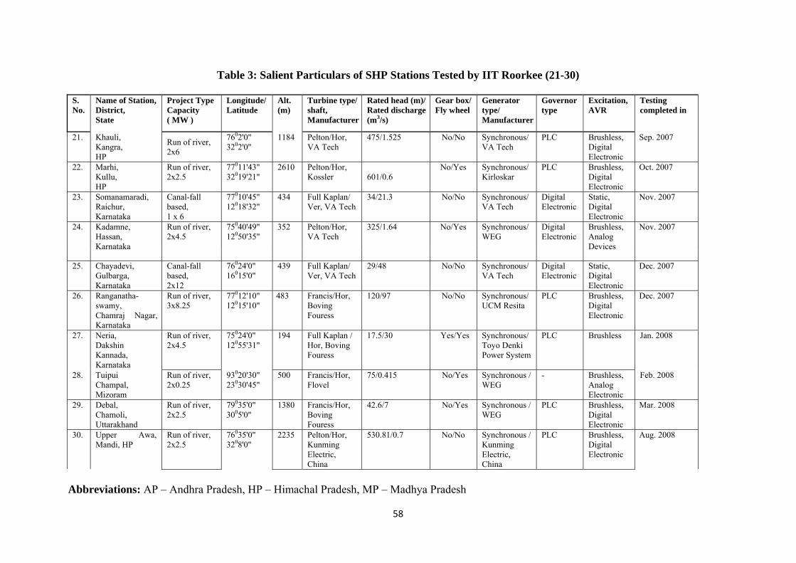
58
Table 3: Salient Particulars of SHP Stations Tested by IIT Roorkee (21-30) S. No.
Name of Station, District, State
Project Type Capacity ( MW )
Longitude/ Latitude
Alt. (m)
Turbine type/ shaft, Manufacturer
Rated head (m)/ Rated discharge (m3/s)
Gear box/ Fly wheel
Generator type/ Manufacturer
Governor type
Excitation, AVR
Testing completed in
21. Khauli, Kangra, HP
Run of river, 2x6
7602'0" 3202'0"
1184 Pelton/Hor, VA Tech
475/1.525 No/No Synchronous/ VA Tech
PLC Brushless, Digital Electronic
Sep. 2007
22. Marhi, Kullu, HP
Run of river, 2x2.5
77011'43" 32019'21"
2610 Pelton/Hor, Kossler 601/0.6
No/Yes Synchronous/ Kirloskar
PLC Brushless, Digital Electronic
Oct. 2007
23. Somanamaradi, Raichur, Karnataka
Canal-fall based, 1 x 6
77010'45" 12018'32"
434 Full Kaplan/ Ver, VA Tech
34/21.3 No/No Synchronous/ VA Tech
Digital Electronic
Static, Digital Electronic
Nov. 2007
24. Kadamne, Hassan, Karnataka
Run of river, 2x4.5
75040'49" 12050'35"
352 Pelton/Hor, VA Tech
325/1.64 No/Yes Synchronous/ WEG
Digital Electronic
Brushless, Analog Devices
Nov. 2007
25. Chayadevi,
Gulbarga, Karnataka
Canal-fall based, 2x12
76024'0" 16015'0"
439 Full Kaplan/ Ver, VA Tech
29/48 No/No Synchronous/ VA Tech
Digital Electronic
Static, Digital Electronic
Dec. 2007
26. Ranganatha- swamy, Chamraj Nagar, Karnataka
Run of river, 3x8.25
77012'10" 12015'10"
483 Francis/Hor, Boving Fouress
120/97 No/No Synchronous/ UCM Resita
PLC Brushless, Digital Electronic
Dec. 2007
27. Neria, Dakshin Kannada, Karnataka
Run of river, 2x4.5
75024'0" 12055'31"
194 Full Kaplan / Hor, Boving Fouress
17.5/30 Yes/Yes Synchronous/ Toyo Denki Power System
PLC Brushless Jan. 2008
28. Tuipui Champal, Mizoram
Run of river, 2x0.25
93020'30" 23030'45"
500 Francis/Hor, Flovel
75/0.415 No/Yes Synchronous / WEG
- Brushless, Analog Electronic
Feb. 2008
29. Debal, Chamoli, Uttarakhand
Run of river, 2x2.5
79035'0" 3005'0"
1380 Francis/Hor, Boving Fouress
42.6/7 No/Yes Synchronous / WEG
PLC Brushless, Digital Electronic
Mar. 2008
30. Upper Awa, Mandi, HP
Run of river, 2x2.5
76035'0" 3208'0"
2235 Pelton/Hor, Kunming Electric, China
530.81/0.7 No/No Synchronous / Kunming Electric, China
PLC Brushless, Digital Electronic
Aug. 2008
Abbreviations: AP – Andhra Pradesh, HP – Himachal Pradesh, MP – Madhya Pradesh
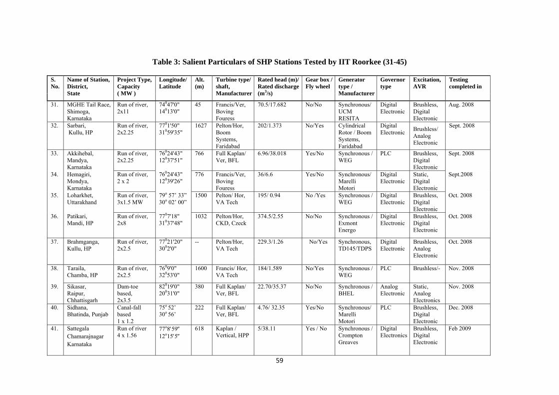
59
Table 3: Salient Particulars of SHP Stations Tested by IIT Roorkee (31-45)
S. No.
Name of Station, District, State
Project Type, Capacity ( MW )
Longitude/ Latitude
Alt. (m)
Turbine type/ shaft, Manufacturer
Rated head (m)/ Rated discharge (m3/s)
Gear box / Fly wheel
Generator type / Manufacturer
Governor type
Excitation, AVR
Testing completed in
31. MGHE Tail Race,
Shimoga, Karnataka
Run of river, 2x11
74047'0" 14013'0"
45 Francis/Ver, Boving Fouress
70.5/17.682 No/No Synchronous/ UCM RESITA
Digital Electronic
Brushless, Digital Electronic
Aug. 2008
32. Sarbari, Kullu, HP
Run of river, 2x2.25
7701'50" 31059'35"
1627 Pelton/Hor, Boom Systems, Faridabad
202/1.373 No/Yes Cylindrical Rotor / Boom Systems, Faridabad
Digital Electronic
Brushless/ Analog Electronic
Sept. 2008
33. Akkihebal,
Mandya, Karnataka
Run of river, 2x2.25
76024'43" 12037'51"
766 Full Kaplan/ Ver, BFL
6.96/38.018 Yes/No Synchronous / WEG
PLC Brushless, Digital Electronic
Sept. 2008
34. Hemagiri, Mondya, Karnataka
Run of river, 2 x 2
76024'43" 12039'26"
776 Francis/Ver, Boving Fouress
36/6.6 Yes/No Synchronous/ Marelli Motori
Digital Electronic
Static, Digital Electronic
Sept.2008
35. Loharkhet, Uttarakhand
Run of river, 3x1.5 MW
79o 57’ 33” 30o 02’ 00”
1500 Pelton/ Hor, VA Tech
195/ 0.94 No /Yes Synchronous / WEG
Digital Electronic
Brushless, Digital Electronic
Oct. 2008
36. Patikari, Mandi, HP
Run of river, 2x8
7707'18" 31037'48"
1032 Pelton/Hor, CKD, Czeck
374.5/2.55 No/No Synchronous / Exmont Energo
Digital Electronic
Brushless, Digital Electronic
Oct. 2008
37. Brahmganga,
Kullu, HP Run of river, 2x2.5
77021'20" 3002'0"
-- Pelton/Hor, VA Tech
229.3/1.26 No/Yes Synchronous, TD145/TDPS
Digital Electronic
Brushless, Analog Electronic
Oct. 2008
38. Taraila, Chamba, HP
Run of river, 2x2.5
7609'0" 32053'0"
1600 Francis/ Hor, VA Tech
184/1.589 No/Yes Synchronous / WEG
PLC Brushless/- Nov. 2008
39. Sikasar, Raipur, Chhattisgarh
Dam-toe based, 2x3.5
82019'0" 20031'0"
380 Full Kaplan/ Ver, BFL
22.70/35.37 No/No Synchronous / BHEL
Analog Electronic
Static, Analog Electronics
Nov. 2008
40. Sidhana, Bhatinda, Punjab
Canal-fall based 1 x 1.2
75o 52’ 30o 56’
222 Full Kaplan/ Ver, BFL
4.76/ 32.35 Yes/No Synchronous/ Marelli Motori
PLC Brushless, Digital Electronic
Dec. 2008
41. Sattegala Chamarajnagar Karnataka
Run of river 4 x 1.56
77o859 12o155
618 Kaplan / Vertical, HPP
5/38.11 Yes / No Synchronous / Crompton Greaves
Digital Electronics
Brushless, Digital Electronic
Feb 2009

60
42. Babehalli Gurudaspur, Punjab
Canal-fall based 2 x 1.35
75o2510 30o015
870 Full Kaplan/ Hor. VA Tech
4/42.0 Yes / Yes Synchronous / WEG
Digital Electronics
Brushless, Digital Electronic
March 2009
43. Hanumanganga Phase-II, Uttarkashi, Uttarakhand
Run of river 1 x 1.95
78o25 30o55
2184 Francis/ Hor, VA Tech
155/1.5 No/Yes Synchronous / TDPS
Digital Electronics
Brushless, Analogue Electronic
June 2009
44. Sahu Chamba HP
Run of river 2 x 2.5
76o1230 32o3156
1013 Francis / Horizontal Kunming Electrical
160/1.94 No/ Yes Synchronous / Kunming Electrical
Digital Electronics
Brushless, Digital Electronic
June 2009
45. Serlui-A Aizawl Mizoram
Run of river 2x0.25 + 1 x 0.5
92o4030 23o4230
500 Turgo Impulse / Horizontal Jyoti
142/0.252 142/0.512
No / No Synchronous / Jyoti
Digital Electronics
Brushless, Thyristrised
July 2009
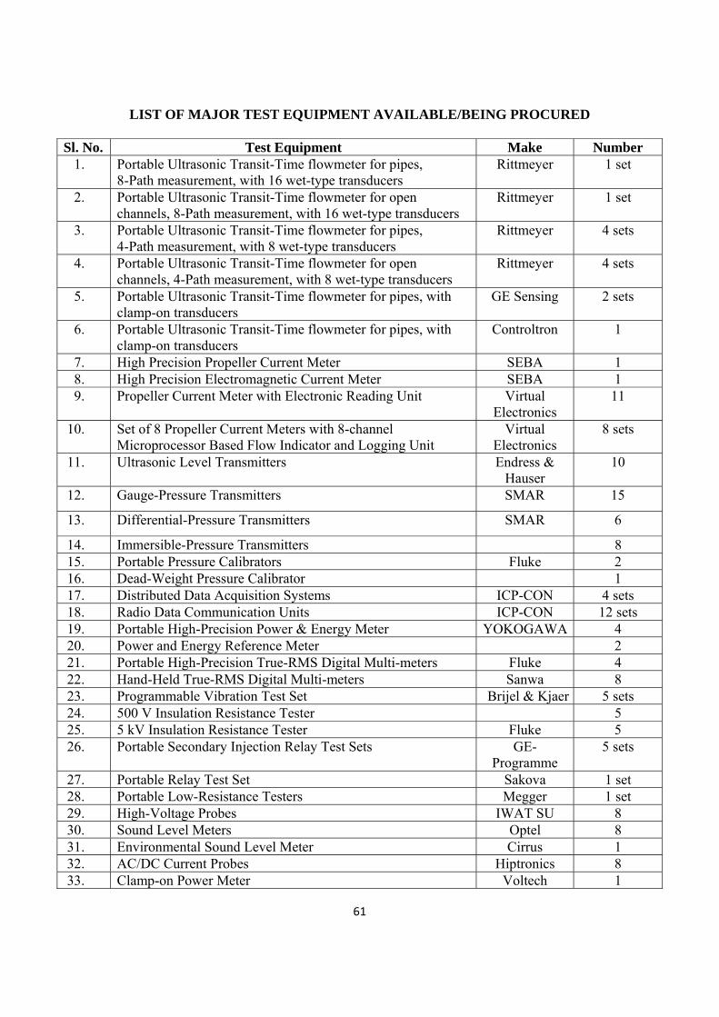
61
LIST OF MAJOR TEST EQUIPMENT AVAILABLE/BEING PROCURED Sl. No. Test Equipment Make Number
1. Portable Ultrasonic Transit-Time flowmeter for pipes, 8-Path measurement, with 16 wet-type transducers
Rittmeyer 1 set
2. Portable Ultrasonic Transit-Time flowmeter for open channels, 8-Path measurement, with 16 wet-type transducers
Rittmeyer 1 set
3. Portable Ultrasonic Transit-Time flowmeter for pipes, 4-Path measurement, with 8 wet-type transducers
Rittmeyer 4 sets
4. Portable Ultrasonic Transit-Time flowmeter for open channels, 4-Path measurement, with 8 wet-type transducers
Rittmeyer 4 sets
5. Portable Ultrasonic Transit-Time flowmeter for pipes, with clamp-on transducers
GE Sensing 2 sets
6. Portable Ultrasonic Transit-Time flowmeter for pipes, with clamp-on transducers
Controltron 1
7. High Precision Propeller Current Meter SEBA 1 8. High Precision Electromagnetic Current Meter SEBA 1 9. Propeller Current Meter with Electronic Reading Unit Virtual
Electronics 11
10. Set of 8 Propeller Current Meters with 8-channel Microprocessor Based Flow Indicator and Logging Unit
Virtual Electronics
8 sets
11. Ultrasonic Level Transmitters Endress & Hauser
10
12. Gauge-Pressure Transmitters SMAR 15
13. Differential-Pressure Transmitters SMAR 6
14. Immersible-Pressure Transmitters 8 15. Portable Pressure Calibrators Fluke 2 16. Dead-Weight Pressure Calibrator 1 17. Distributed Data Acquisition Systems ICP-CON 4 sets 18. Radio Data Communication Units ICP-CON 12 sets 19. Portable High-Precision Power & Energy Meter YOKOGAWA 4 20. Power and Energy Reference Meter 2 21. Portable High-Precision True-RMS Digital Multi-meters Fluke 4 22. Hand-Held True-RMS Digital Multi-meters Sanwa 8 23. Programmable Vibration Test Set Brijel & Kjaer 5 sets 24. 500 V Insulation Resistance Tester 5 25. 5 kV Insulation Resistance Tester Fluke 5 26. Portable Secondary Injection Relay Test Sets GE-
Programme 5 sets
27. Portable Relay Test Set Sakova 1 set 28. Portable Low-Resistance Testers Megger 1 set 29. High-Voltage Probes IWAT SU 8 30. Sound Level Meters Optel 8 31. Environmental Sound Level Meter Cirrus 1 32. AC/DC Current Probes Hiptronics 8 33. Clamp-on Power Meter Voltech 1

62
Sl. No. Test Equipment Make Number Instruments
34. Clamp-on Digital Multi-meter MECO 1 35. Non-contact Thermometers Omega 8 36. Non-contact Tachometers Systems &
Control 8
37. Electronic Total Station Leica 1 38. Global Positioning System 1 39. Hand-Held digital Altimeter 1 40. High-Current Portable Contact Resistance Tester 1 41. Earth Resistivity Tester Electronics
Appliances 1
42. Cable Fault Locator 1 43. High-Voltage Capacitance and Tan-Delta Test Set AVO
International 1 set
44. ELCID Tester Adwell International
1 set
45. Portable Partial Discharge Detector Hatro Handler 1 46. High-Pot Tester 1 47. Ultrasonic Flaw Detector Modosonic
Instruments 1
48. Ultrasonic Thickness Meter Modosonic Instruments
1
49. Eddy-Current Crack Detector Technofour 1 50. Micro Cover Meter ELE
International 1
51. Ultrasonic Concrete Tester Proceq 1 52. Concrete Hammer, M type Proceq 1 53. Concrete Hammer, N type James
Instruments 1
54. Portable Horizontal Acoustic Doppler Current Profiler RD Instruments
3
55. Portable Vertical Acoustic Doppler Current Profiler RD Instruments
1
56. Precision-class process calibrator with pumps Fluke 1 57. Thermometer probes for measuring differential temperature
across hydro turbine Sea Bird
Electronics 6
58. Miscellaneous instruments, spares & fixtures 59. Immersible Pressure Transducer Sensor
Techniks 15
60. Digital Storage oscilloscope Scintific Instruments
1
61. Magnetic Drill Machine Euroboor 1 62. Replacement of transducer, Additional components of Flow,
Flow simulation for risonic 1 set

63
Sl. No. Test Equipment Make Number 63. Smart pressure transmitter with universal HART Calibrator Smar 2 64. Thickness gauge GE Sensing 2 65. Portable Ultrasonic level transmitter Endress &
Hauser 4 nos.
66. Fast-response Pressure transducers (1 set of 8 nos.) Burket 1 set 67. Constant Temperature Well with reference thermometer Fluke 1 set 68. Data Acquisition Systems Graphtec 2 nos. 69. Precision Propeller Current Meter (1 set of 30 nos.) SEBA 1 set 70. Ultrasonic transit time transducers for mounting inside the
penstock along with penetrator (1 set) Rittmeyer 1 set
71. Laser Distance Meters Fluke 3 72. Digital Turns Ratio Tester Megger 4 73. UHF Communication Set Motorola 4 sets