Embed Size (px)
Citation preview

1
PERFORMANCE TESTING FOR AUTOMOTIVE WIRE HARNESS TAPES
Amanda E. Safford, Product Development Testing Engineer, Berry Global, Franklin, KY
Abstract
Wire Harnesses are the communication network in every vehicle; providing the lifeblood to components
like brakes, steering, engine control, passenger safety and comfort features. Wire harnesses act on the idea
of safety in numbers for the wires, connectors, terminals and clamps that carry and complete important
automotive operational messaging. Wrapping wire harnesses in tape provides essential protection while
performing many additional functions. Tapes reduce automotive buzz, squeak and rattle, shield with heat
reflective properties, aid in trouble shooting and organization with critical color coding and fortify the
wire harness against abrasion. Durability of the tape can determine driver safety and reduce ownership
costs with less maintenance. Tape is a crucial line of defense for the expansive wiring that totals over a
mile in modern vehicles.
Wire Harness tapes are tested to OEM performance specifications during design and annually thereafter.
Validation covers the magnitude of environmental and operational stresses that a harness tape will
experience in a ten or more, year lifespan. Understanding real world applications is essential to
appreciating the role each required testing criteria plays. With expanding electrical system designs and the
need for increased product life expectancy, the stakes are raised. Assessments in a performance
specification include, amongst others, resistance against automotive fluids, aging at specified operating
temperatures, abrasion resistance, noise damping and flame retardant properties.

2
PERFORMANCE TESTING FOR AUTOMOTIVE WIRE HARNESS TAPES
Amanda E. Safford, Product Development Testing Engineer, Berry Global, Franklin, KY
1.0 Introduction
The modern vehicle is a marvel; a product of sophisticated systems and components working in harmony
to get from point A to point B. Consumers depend on vehicle manufacturers to provide safe and reliable
products to transport cherished family and friends. Consequently, vehicles are subjected to rigorous impact
testing by both government entities and insurance groups. The National Highway Traffic Safety
Administration (NHTSA) began testing and rating vehicles with the use of crash test dummies in 19781.
These violent images can shock us into wearing our seat belts and scare us into changing dangerous
behaviors like texting while driving. Ratings are published and are required on all new vehicle window
labels. Equally as important as crash testing, though less emotion inducing, is the testing required for the
materials building our vehicles and the components and systems within them.
2.0 Systems, Components and Performance Specifications
Automobiles are complicated machines made of smaller subsystems. In recent years, the intricacies and
expansions of one such system, the electrical and electronics system is upping the ante on component
performance and protection requirements. Automotive electrical systems distribute information to other
critical systems and components like brakes, steering, engine control as well as passenger safety and
comfort features. Cars are coming off the lots with rear video imaging, lane departure warning, forward
collision warning and even automatic emergency braking which the NHTSA now recommends as driver
assistance technologies2. These important tools rely upon the translation and transportation of input signals
from the environment into vehicle system alerts and adjustments. Whether a safety accessory or a comfort
feature, these components and many others, rely on the distribution of important electrical information.
The system communicating this critical data must be protected during its tenure. Designed under the
premise of safety in numbers, automotive electrical systems are made up of wire harnesses; where these
harnesses group and protect the wires, connectors, terminals and clamps that carry and complete the
important electrical messaging.
Harness covering solutions include pressure sensitive adhesive (PSA) tapes, heat-shrink tubing, split loom
and nylon braids3. Specifically, PSA tapes play a key role in protecting the wires and other parts making
up the electrical system while performing additional functions. PSA tapes used in the automotive industry
are subject to required design and validation testing set forth by original equipment manufacturers (OEMs)
to test these key elements. Cars experience the daily grind and OEM performance specifications aim to
validate against the magnitude of environmental and operational stressors a harness tape will endure in an
automobile’s average 10 year, or greater, lifespan4.
The following OEM engineering and performance specifications5,6,7 are extensive industry examples to
which PSA tape manufacturers commonly design and validate wire harness tapes:

3
Table 1: Performance Specifications of Major US Manufacturers
OEM Specification Number Title
Ford Engineering
Specification
ES-AC3T-1A303-AA Harness Tape
Performance
Specification
Fiat Chrysler
Automobiles
MS.90111 Tape with Adhesive or
without Adhesive for
Electrical Wiring
GM Worldwide
Engineering Standards
GMW 16740 General Specification -
Harness Tape
OEM performance specifications are vast and include many required elements as well as optional levels
of performance in specialty categories. When reading one of these performance specifications, it is
motivating to correlate real-life situations or even the applied purpose of the tape to the actual nuts and
bolts of the test method. Why is this testing required? How does this test translate into a real-life scenario?
Where do the results of these tests tie into what is truly important to the overall safety or comfort of the
automotive consumer? Some interesting tests can be grouped and discussed in the following categories:
Durability and Safety
Heat Aging
Abrasion Resistance
Flame Retardant Properties
Automotive Fluid Resistance
Heat Reflectivity/Thermal Effectiveness
Comfort and Driver Experience
Fogging Levels
Noise Damping
Weather and Environmental Impacts
Environmental Cycling
Cold Flex
Thermal Overload
With an understanding of each test and how the results translate into performance during operation,
products can be designed to meet different levels within performance categories. Additionally, product
data sheets referencing certain overall specifications or key specialty tests can aid an engineer in choosing
the proper tape for a specific harness design or lead a consumer to aptly choose a tape during maintenance
and servicing.
Tapes are tested fully during development and annually. Some tests are chosen as regular checks utilized
during each production run for QA purposes. At first glance, the logic for some testing is more obvious
than others, but all of the testing either addresses a property that relates to tape performance indicating
durability and safety, influence over driver comfort and overall user experience, or response and resistance
to environmental factors.

4
3.0 Durability and Safety
3.1 Heat Aging
Durability of harness wrapping tape can determine driver safety and reduce ownership costs with less
maintenance. Tape is a crucial line of defense for the expansive wiring that totals over a mile in modern
vehicles8. Good performance after aging of the tape is an essential measure of the functionality of the tape.
OEM specifications generally categorize tapes into performance groups by suggested operating
temperatures. According to Ford’s Performance Specification, operating temperatures are divided into 6
classes, defined as A through F. These classes can be correlated with their recommended application and
location within an automobile, as proposed in the International Standard, ISO 16750, Part 4: Climatic
Loads9 and seen below.
Table 2: Temperature Rating according to Ford Specification ES-AC3T-1A303-AA
Temperature Rating Class General Application/Mounting Location
Examples
- 40 to 85 °C A Passenger compartment out of radiation exposure
Inside luggage compartment
Inside doors, lids, exterior cavities (wheel housings)
- 40 to 100 °C B Engine compartment frame
Passenger compartment exposed to direct solar
radiation
Passenger compartment exposed to radiated heat
- 40 to 125 °C C Engine compartment in/on plenum chamber
On engine/In engine
On engine compartment cover
- 40 to 150 °C D Engine compartment on or in transmission/retarder
Engine compartment to body - 40 to 175 °C E
- 40 to 200 °C (+) F
Selection or design of a wire harness tape typically starts with its temperature class. With an average 10-
year life span and the Federal Highways Administration (FHA) estimated 10,164 average annual miles
per vehicle in 2017, vehicles likely see 101,640 miles, or more, in an average lifetime10. Under the Ford
specification, all tapes are required to be heat aged for 3000 hours at their designed operating temperature.
Ford and others require this long term 3000 hour aging, though test specimen preparations can differ
between specifications.
Why 3000 hours? Using the FHA 2017 estimates of a 25 mph average commute10 speed and a 10-year-
old vehicle with 101,640 miles, a car operates 4,065 hours. If a car with 101,640 miles averages a commute
speed of 50 mph, operating hours are 2,032. Coincidentally, if we project a vehicle with 150,000 miles
travels an average of 50 mph during its lifetime, operating hours are 3,000; exactly the aging hours
indicated in many performance specifications. A 3000-hour exposure to heat tests with the intent to ensure
the life of performance parts use throughout a vehicle.

5
Heat aging is completed by actually building bench size wire harnesses and exposing them to operating
temperatures for the duration of 3,000 hours. Figure 1 below shows an example of the Ford specification
wire harness. Tape is generally wound in a half-lapping style around a convolute, numerous wires, or even
two inter-twined wires of a required type and size. Intermittently, and at total exposure, harness bundles
are evaluated for performance indicators and manually wound around designated circumference mandrels.
Winding of the harnesses around the mandrels stresses the half laps of the tape. Tape backings are
evaluated for cracks and melting while the ends are checked for flagging, a term for the release of the
open lap at the end of the bundle. Heat aging is a critical long term test meant to validate both the vigor
of the backing and the stability of the adhesive in a tape as it operates throughout its life in a vehicle.
Figure 1: Ford Performance Specification Bench Scale Harness
3.2 Abrasion Resistance
Tapes see more than heat. Vehicles are designed to move. As vehicles travel along bumpy roads and
highways, while moving parts create constant vibration, harnesses are exposed to tremendous abrasion
risk. Tapes are often designed and selected for their performance against the abrasion a wire harness may
experience. Imagine, if wires connecting the sensors of a vehicle’s airbags and main controller were
rubbing against engine parts just slightly during every mile driven; if left uncovered, a small continuous
rub would ultimately result in the exposure of the wire’s conducting core and leave the driver with a
warning light and the need for expensive trouble shooting. In a worst case scenario, the air bag will not
deploy when it should and an injury will occur during impact in an accident.
Abrasion resistance is evaluated using numerous methods. Ford requires needle style stroke abrasion and
labels abrasion protection as a Wear Resistance category. The various levels of wear categories are as seen
in Table 3.
Needle Abrasion is performed by adhering one layer of the tape to a steel rod with a diameter of 10 mm.
The test is an altered version of ISO 6722 to accommodate testing tape instead of the insulation on a single
strand of wire11. The diameter of the horizontal scraping needle is 0.45 mm. The needle is changed at each

6
test. The scrape test occurs down the center of the tape. The needle is weighted from above. The scrape
abrasion stops when electrical contact is made between the steel rod and the abrading needle; when a hole
in the protecting tape surface has been worn. Figures 2 shows the needle and tape set up for testing.
Table 3: Wear Resistance Categories
Wear Category Requirement (Double Strokes)
0 – No wear protection < 100
1 – Little wear protection 100 – 499
2 – Medium wear protection 500 – 999
3 – High wear protection 1000 – 4999
4 – Very high wear protection 5000 – 14999
5 – Ultra high wear protection 15000 – 29999
6 – Super high wear protection > 29999
N – Not tested N/A
Figure 2: Needle Abrasion Testing
The final number of double strokes by which a tape is rated, across and back equaling a double stroke, is
determined by the mean of ten iterations of the test. It should be noted that most harnesses are half-lap
wrapped resulting in a double layer of tape along the entire harness covering, while the test merely
examines the durability of a single layer.
Abrasion results help harness design engineers choose tapes with a protection level required for wires
traveling through potentially wearing transitions between the body and engine compartment, running
along tight locations in doors and bending around curves and corners throughout the vehicle.
3.3 Flame Retardant Properties
Tapes applied to protect the wires and components of harnesses are also tested for flame retardant
properties. Heat aging performance and abrasion resistance indicate how a tape will age over a lifetime
and handle repeated stress. Flammability testing informs a design engineer how a tape will help protect

7
the components within the harness system, the vehicle, and in turn, the driver, against the worst – the
spread of fire.
OEM performance specifications typically require flammability to be evaluated according to the
horizontal method described in ISO 3795-198912. This International Standard outlines the determination
of burning characteristics for materials utilized in vehicles interiors.
Flammability testing per ISO 3795-1989 utilizes a rectangular combustion chamber with a gas burner at
one end and a hole for introduction of the sample and a holder in the other end. The sample holder exposes
one end of a tape strip horizontally to a 1.5-inch-high flame for 15 seconds. Tapes are generally tested
with the backing side down to the flame; indicating their purpose as a line of defense against exterior
flames.
Burning distance (D) is measured in millimeters by observing the front of the flame as it propagates from
one marker point to another or where the flame burns out; whichever is first. A timer is started and stopped
at the first and final markers, giving a burn time (T) in seconds. The overall characteristic determines,
Burning Rate (B), which is given in millimeters per minute and calculated using Equation 1 as shown
below.
𝐵 =𝐷
𝑇 𝑥 60 (Equation 1)
The Ford specification requires harness tapes have a burn rate of no more than 100 millimeters per minute;
less than 4 inches per minute. Ensuring that tapes meet or exceed this Ford requirement and others, helps
reduce the proliferation of a fire within a vehicle, protects the electrical system, and buys precious time
for drivers and passengers in an emergency situation.
3.4 Automotive Fluid Resistance
Tapes wrap wire harnesses to ultimately help protect a driver from electronic failure. Coincidentally,
drivers have the potential to influence the longevity and performance of certain harnesses throughout the
engine compartment every time they top off their engine oil, refill the windshield wiper fluid, add coolant,
and more. Most drivers can relate to spilling some fluid while refilling and helplessly watching the spill
trickle onto the visible engine parts and flow or drip down into the dark spaces hands cannot easily fit to
wipe and clean up the mess.
As a car ages, fluids can also seep from leaking hoses and connections throughout engine, batteries can
potentially leak acid and degreasers used around the engine during servicing can drip or over-spray onto
adjacent harnesses; all of these possibilities posing a threat of destroying tape protecting wire harnesses
and causing corrosive damage. Even salt spread across roads during the winter months can influence
longevity of a wire harness if the tape is not designed and tested to resist salt corrosion. Given the high
likelihood of harnesses being exposed to all of these potentially damaging fluids, OEM specifications
require thorough examination of a wire harness tape’s resistance against a multitude of automotive fluids
at room temperature and at elevated temperatures over an extended period of time.
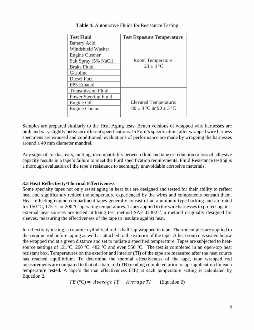
The Ford specification requires tapes to be immersed or saturated in the following fluids for 5 minutes
before being drained and conditioned for 72 hours and aged prior to evaluation.
8
Table 4: Automotive Fluids for Resistance Testing
Test Fluid Test Exposure Temperature
Battery Acid
Room Temperature:
23 ± 3 °C
Windshield Washer
Engine Cleaner
Salt Spray (5% NaCl)
Brake Fluid
Gasoline
Diesel Fuel
E85 Ethanol
Transmission Fluid
Elevated Temperature:
80 ± 3 °C or 90 ± 3 °C
Power Steering Fluid
Engine Oil
Engine Coolant
Samples are prepared similarly to the Heat Aging tests. Bench versions of wrapped wire harnesses are
built and vary slightly between different specifications. In Ford’s specification, after wrapped wire harness
specimens are exposed and conditioned, evaluations of performance are made by wrapping the harnesses
around a 40 mm diameter mandrel.
Any signs of cracks, tears, melting, incompatibility between fluid and tape or reduction or loss of adhesive
capacity results in a tape’s failure to meet the Ford specification requirements. Fluid Resistance testing is
a thorough evaluation of the tape’s resistance to seemingly unavoidable corrosive materials.
3.5 Heat Reflectivity/Thermal Effectiveness
Some specialty tapes not only resist aging in heat but are designed and tested for their ability to reflect
heat and significantly reduce the temperature experienced by the wires and components beneath them.
Heat reflecting engine compartment tapes generally consist of an aluminum-type backing and are rated
for 150 °C, 175 °C or 200 °C operating temperatures. Tapes applied to the wire harnesses to protect against
external heat sources are tested utilizing test method SAE J230213, a method originally designed for
sleeves, measuring the effectiveness of the tape to insulate against heat.
In reflectivity testing, a ceramic cylindrical rod is half-lap wrapped in tape. Thermocouples are applied to
the ceramic rod before taping as well as attached to the exterior of the tape. A heat source is seated below
the wrapped rod at a given distance and set to radiate a specified temperature. Tapes are subjected to heat-
source settings of 121°C, 260 °C, 482 °C and even 550 °C. The test is completed in an open-top heat
resistant box. Temperatures on the exterior and interior (TI) of the tape are measured after the heat source
has reached equilibrium. To determine the thermal effectiveness of the tape, tape wrapped rod
measurements are compared to that of a bare rod (TB) reading completed prior to tape application for each
temperature tested. A tape’s thermal effectiveness (TE) at each temperature setting is calculated by
Equation 2.
𝑇𝐸 (°C) = 𝐴𝑣𝑒𝑟𝑎𝑔𝑒 𝑇𝐵 − 𝐴𝑣𝑒𝑟𝑎𝑔𝑒 𝑇𝐼 (Equation 2)

9
Essentially, the higher the Thermal Effectiveness (TE) value at a given test temperature, the more effective
the tape is at reflecting heat from the wires and components it protects. Engineers designing wiring
harnesses traveling through a hot engine compartment can use these ratings to best select the protection
level needed for the route required.
4.0 Comfort and Driver Experience
Safety and performance are not the only factors addressed in automotive specification testing. Harness
tapes used inside or near the passenger compartment are also designed to ensure and enhance a positive
driver experience. Wire harnesses run through tight spaces inside doors, throughout the dashboard, along
beams, and sometimes even overhead. Tapes can protect wire harness, but if used in the wrong space or
designed incorrectly, they can inhibit the driver experience.
4.1 Fogging
With the driver in mind, a tape is designed and tested for a characteristic called fogging. Fogging
addresses, a unique problem. If a tape under heat exposure releases particulates, oils, water vapor or
plasticizers; this will ultimately condense on surfaces inside the vehicle as the temperature cools. The
resulting condensation can produce a fog on windows or a film on vehicle interior surfaces, neither of
which being favorable.
Tapes tested to the Ford specification are required to produce a fogging number of 20 or less. This value
is a measure of initial (Ri) and final (Rf) optical gloss values on glass panels. Glass panels are placed atop
400 mL tall form 80 mm circumference beakers. At the bottom of the beaker lies a tape sample applied to
aluminum. The beakers are lowered into a 100 °C heating bath while the glass panels are topped with
cooling blocks, chilling the panels to 21 °C. The environment created facilitates condensation and is
maintained at those conditions for 3 hours.
At the end of exposure, the cooling blocks are removed and the panels are placed flat on a black surface
with the condensation catching side up. Gloss readings are taken at 1 hour after conditioning at room
temperature and 16 hours later. Extensive cleaning of the glass reference panels and beakers ensues to
make sure that the readings are truly reflecting only materials released by the heated tape specimen.
Fogging numbers are determined by Equation 3 as seen below.
𝐹𝑜𝑔𝑔𝑖𝑛𝑔 𝑁𝑢𝑚𝑏𝑒𝑟 =𝑅𝑓
𝑅𝑖 × 100 (Equation 3)

10
Figure 3: Fogging Heating Bath with beakers, glass panels and cooling plates
4.2 Noise damping
Noise prevention in automobiles includes Buzz, Squeak, and Rattle (BSR) tapes and other Noise,
Vibration, and Harshness (NVH) products14. BSR tapes prevent or minimize noise to enhance driving
experience. These tapes are generally soft and fluffy; designed to cushion the impact between components.
NVH products also work to reduce driver experienced noise by absorption of sound energy, but are not
common as harness wrapping materials.
As cars age, parts within age as well. Clips break and harnesses begin moving more within the space
available. Conversely, as electrical system intricacies increase, new vehicle harnesses can become
crowded. Harnesses can be in closer proximity to other components or even more compressed between
vehicle frames and interior enclosures. In all of these situations, the likelihood of rattles and squeaks is
high. Parts or frames and harnesses bumping and tapping routinely can create an annoying orchestra
behind the dashboard or within a doorframe.
Harnesses routed through tight or cramped areas are prime candidates for BSR tapes. The Ford
specification breaks tapes into the following noise damping categories:
Table 5: Noise Reduction Categories
Noise Damping Category Requirement [dB(a)]
0 – No noise dampening 0 to ≤2
1 – Little noise dampening <2 to ≤5
2 – Medium noise dampening <5 to ≤10
3 – High noise dampening <10 to ≤15
4 – Very high noise dampening <15
N – Not tested N/A

11
Noise reduction of a tape is measured by covering an 8 mm steel bar with one wrap of tape. A lever is
pulled to release the steel bar, dropping it from a height of 20 mm onto an arched aluminum plate with a
force of 0.16 N. The test procedure is a standardized set-up and Figure 4 is a schematic of the test fixture:
Figure 4: Noise Testing Fixture
Above the steel rod is a sound meter which measures resulting decibels from the rod and plate collision.
Readings are taken 10 times at the same point of impact. Values are recorded for the bare steel rod and
the difference in decibels, dB (A) or noise reduction from bare to covered rod determines a tape’s noise
reduction performance category.
5.0 Weather and Environmental Impacts
Automobiles are routinely subjected to extreme temperature variations due to the difference between
ambient and operating temperatures. Ideally, all vehicles would be garage kept, keeping ambient
temperatures warmer and reducing the temperature fluctuations harness tapes may experience as a vehicle
warms up, operates and cools down; a cycle possibly experienced multiple times a day for much of its life
time.
5.1 Environmental Cycling
Environmental Cycling requirements test and confirm that tapes can withstand the stresses that heating
and cooling cycles exert on the electrical systems. In the Ford specification, bench size harnesses are
built and tested to seven cycles in the following exposure sequence:
3 hours at service/operating temperature
2 hours at uniform cool down to - 40 ± 2 °C
3 hours at - 40 ± 2 °C
1 hour uniform heat up and humidification to 38 ± 2 °C and 95-98 % Relative Humidity
1 hour at 38 ± 2 °C and 95-98 % Relative Humidity
1 hour uniform heating and drying to service temperature

12
After the seven cycles and required reconditioning, exposed bundles are evaluated in a manner similar to
Fluid Resistance bundles. Tapes pass this test if minimum flagging and no indications of deterioration of
the backing or adhesive is exhibited after wrapping the bundle around a 40 mm mandrel.
5.2 Cold Flex
Similarly, tape behavior is evaluated in excessively cold environments. Per the Ford specification, bundles
are prepared for Cold Flex testing and exposed to -40 °C for 4 hours while weighted with 0.5 kg and
attached to a 20 mm mandrel. As seen below in Figure 5, samples are wrapped by turning the mandrel
while still cold after 4 hours of exposure. Samples are brought to room temperature and reviewed for
defects.
Figure 5: Cold Flex Testing
5.3 Thermal Overload
Conversely, samples are inspected for exposure to excessive heat as well. Temperatures within the engine
compartment as well as in the passenger compartment can climb significantly in certain situations. Interior
temperatures can escalate in hot summer heat and engines can overheat or maintain and build heat after a
drive when parked in direct sunlight during the hot summer months. Thermal Overload requires bench
bundles be exposed to 50 °C above a harness tape’s operating temperature for 6 hours. As in the previously
reviewed tests, fatigued bundles are wrapped around a 40 mm mandrel, stressing the heat exposed tape
backing and adhesive. Thermal Overload testing strictly and ruthlessly evaluates performance and safety
of protection providing harness wrapping tapes.
6.0 Conclusion - Tapes, Testing and Owner Confidence
Pressure sensitive adhesive tapes are used in many areas of automobile manufacturing and servicing.
Specifically, wrapping wire harnesses in tape provides critical protection that ensures the safety, reliability
and positive experience consumers expect and vehicle manufactures aim to deliver. Testing harness tapes
to OEM performance specifications provides crucial information to design engineers and after-market
service providers. A true understanding of real world application is beneficial to appreciating the role each
required testing criteria plays in continuing consumer trust and OEM dependability.

13
7.0 Citations
1. National Highway Traffic Safety Administration (n.d.). Timeline of NHTSA’s 5-star Safety
Ratings program. Retrieved from https://www.nhtsa.gov/ratings.
2. National Highway Traffic Safety Administration (n.d.). Recommended Driver Assistance
Technologies. Retrieved from https://www.nhtsa.gov/ratings.
3. Weber, A. (2016, October 4). Options for Protecting Wire Harnesses. Retrieved from
https://www.assemblymag.com.
4. Walsworth, J. (2016, November 22). Average age of vehicles on road hits 11.6 years. Retrieved
from https://www.autonews.com.
5. Ford Motor Company. (2007, June 20). Specification – Wiring Harness Tape Performance. ES-
AC3T-1A303-AA. Version Date 20150504.
6. Godlewski, M, Bianco, L. (2015, December 16). Tape with Adhesive or Without Adhesive for
Electrical Wiring. MS.90111. Fiat Chrysler Automobiles. Retrieved August 18, 2016.
7. GM Worldwide Engineering Standards. (2012, November). General Specification – Harness
Tape. GMW16740. Version November 2012.
8. Sprovieri, J. (2014, July 1). Wire Harness Recycling. Retrieved from
https://www.assemblymag.com.
9. International Organization for Standardization. (2003). Road vehicles – Environmental
conditions and testing for electrical and electronic equipment. Part 4: Climatic loads. ISO
16750-4:2003(E). First Edition 2003-12-15.
10. McGuckin, N., Fucci, A. (2018, July). Summary of Travel Trends: 2017 National Household
Travel Survey. Report prepared for Federal Highway Administration by Westat, Rockville, MD.
11. International Organization for Standardization. (2006). Road vehicles – 60 V and 600 V single-
core cables – Dimensions, test methods and requirements. ISO 6722:2006(E). Second Edition
2006-08-01.
12. International Organization for Standardization. (1989). Road vehicles, and tractors and
machinery for agriculture and forestry – Determination of burning behavior of interior
materials. ISO 3795:1989(E). Second Edition 1989-10-15.
13. SAE International. (1996, November). Surface Vehicle Standard – Thermal Effectiveness of
Sleeve Insulation. SAE J2302 FEB2011. Version February 2011.
14. Adhesives & Sealants Industry Online. (2005, March 1). PSAs for Automotive Bonding and
Noise Reduction. Retrieved from https://www.adhesivesmag.com.

14
8.0 Acknowledgements
I wish to thank my colleagues at Berry Global for all of their assistance and care during the writing of
this paper. The reliable support of my technicians Robbie Johnson and Kim Haley kept our lab on track
and I especially thank Roland Horst and Soujanya Muralidhara for their time and wise editorial input
during the final stages. To all who read this paper before publishing, I thank you. All the best.