Embed Size (px)
Citation preview

PERFORMANCE STUDY OF FOUR MIRROR LASER RESONATOR
FOR 6 m MINIMUM BEAM SIZE USING GREEN LASER OSCILLATOR
Arpit Rawankar #A,B), Junji Urakawa A,B), Hirotaka Shimizu B),
Nobuhiro Terunuma A,B) ,Yosuke Honda B)
A) Department of Accelerator Science, School of High Energy Accelerator Science, Graduate
University for Advanced Studies, Shonan International Village, Hayama, Miura, Kanagawa , Japan B) High Energy Accelerator Research Organization [KEK], 1-1 Oho, Tsukuba, Ibaraki , Japan
Abstract
The Accelerator Test Facility (ATF) was constructed at KEK to study low emittance beam physics and to develop the
technologies associated with it. In ATF damping ring, electron beam size is measured with laser wire system based on
Compton scattering. A new four mirror laser wire system is developed for this purpose. This system has many
advantages over two mirror laser wire system. Four mirror resonator reduces the sensitivity towards misalignment as
compare to two mirror resonator. Measured Finesse of resonator is more than 4000. Optical cavity has enhancement
factor of 1900. Inside ATF damping ring, electron beam has very small size of 10 in vertical direction. To measure
electron beam profile, very thin laser beam size is needed. Laser waist size, around 6 in sagittal plane is achieved in
between two concave mirrors. Special type of mirror alignment scheme is used to make a compact four mirror optical cavity. Laser resonator is designed to work in vacuum environment with a complex mirror holder design .We report the
performance studies of such four mirror resonator using 532 nm CW laser oscillator in this research.
1. Introduction
Production and handling of low emittance beam is
important technology for linear colliders. For this
damping ring generates low emittance beam by radiation
damping process. The Accelerator Test Facility (ATF) in
KEK is a test accelerator to examine the technical
possibility in generating the low-emittance beam required
for linear colliders. The damping ring has two arc sections
and two straight sections [1]. In the damping ring at ATF,
vertical beam size is less than 10 m. For emittance
measurement, we are developing a new type of beam
profile monitor which works on the principle of Compton
scattering between electron and laser light. A thin and
intense laser beam is produced by exciting a Fabry-Perot
optical cavity and it is scanned across the electron beam
in perpendicular direction as shown in Figure 1.
Figure 1: KEK-ATF Damping Ring
When electron beam crosses the laser, some of the
electrons interact with laser light and emit energetic
photons in the forward direction via the Compton
scattering process. A detector placed downstream of the
collision point measures the flux of the scattered photons.
By scanning the position of laser beam and counting the
number of scattered photons, a projected beam size is
obtained. Such type of optical resonator system is called
laser wire. Laser wire is one of such a technique to
measure a small electron beam size. In particular, if both
electron and laser beam are assumed to have Gaussian
profiles with width and , the observed profile is
also gaussian with width 𝑜𝑏𝑠 expressed by
σobs2 = σlw
2 + σe2 (1)
We used a four mirror Fabry-Perot optical cavity to produce laser wire. It enhances the effective laser power
and improves the intensity of the signal. The geometrical
properties of laser beam are completely defined by
boundary conditions formed with two concave mirrors
and two plane mirrors [2, 3]. The minimum beam waist is
obtained in between two concave mirrors. The two
concave mirrors of same curvature are used in compact
resonator. Electron beam interacts with laser pulse at
minimum beam waist position, which is called interaction
point (IP).
Aspect ratio of resonator is important parameter to achieve small beam waist. Aspect ratio of resonator is
defined as ratio of side by side plane and concave mirror
Proceedings of the 10th Annual Meeting of Particle Accelerator Society of Japan (August 3-5, 2013, Nagoya, Japan)
- 760 -
distance (d) to distance between two concave mirrors (L).
The Aspect ratio for four mirror optical resonator is
given as [2]
= ⁄ . (2)
To achieve very small minimum beam waist, aspect ratio of cavity is kept constant and cavity length is reduced.
2. Design of compact resonator
2.1 Design values and mirror alignment scheme
The optical cavity assembly consists of four mirrors,
mirror holder system and cyilindrical spacers which
define length of cavity. In order to have precision control
over cavity length , both plane mirror holders were
supported by a piezo actuator through a disk type plate
spring. Hollow piezo actuators are used for laser beam to
pass through them [4]. Four mirror optical cavity is
designed for 532 nm wavlength. Distance between concave-concave mirror is kept at 102.8 mm and distance
between plane-plane mirror is kept at 103.2 mm. A
complex mirror alignment scheme as hown in Figure 2 is
used to keep side by side distance between plane and
concave mirror to 29.2 mm. All mirrors used in cavity
design are of 1 inch diameter. The radius of curvature for
two concave mirror is 101.81 mm.
Figure 2. Cavity assemply and its mounting.
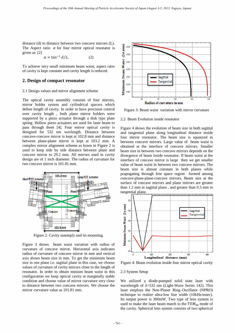
Figure 3 shows beam waist variation with radius of
curvature of concave mirror. Horizontal axis indicates
radius of curvature of concave mirror in mm and vertical
axis shows beam size in mm. To get the minimum beam size in one plane i.e. sagittal plane in this case, we choose
values of curvature of cavity mirrors close to the length of
resonator. In order to obtain minium beam waist in this
configuration we keep optical cavity at marginally stable
condition and choose value of mirror curvature very close
to distance between two concave mirrors. We choose the
mirror curvature value as 101.81 mm.
Figure 3: Beam waist variation with mirror curvature
2.2 Beam Evolution inside resonator
Figure 4 shows the evolution of beam size in both sagittal
and tangential plane along longitudinal distance inside
four mirror resonator. The beam size is squeezed in
between concave mirrors. Large value of beam waist is
obtained at the interface of concave mirrors. Smaller
beam size in between two concave mirrors depends on the
divergence of beam inside resonator. If beam waist at the
interface of concave mirror is large then we get smaller
value of beam waist in between two concave mirrors. The
beam size is almost constant in both planes while
prapogating through free space region formed among concave-plane-plane-concave mirrors. Beam size at the
surface of concave mirrors and plane mirrors are greater
than 1.2 mm in sagittal plane , and greater than 0.3 mm in
tangential plane.
Figure 4: Beam evolution inside four mirror optical cavity
2.3 System Setup
We utilized a diode-pumped solid state laser with
wavelength of 𝜆=532 nm (Light-Wave Series 142). This
laser employs the Non-Planer Ring–Oscillator (NPRO)
technique to realize ultra-low line width (10kHz/msec).
Its output power is 300mW. Two type of lens system is
used to make the laser beam match to the mode of
the cavity. Spherical lens system consists of two spherical
Proceedings of the 10th Annual Meeting of Particle Accelerator Society of Japan (August 3-5, 2013, Nagoya, Japan)
- 761 -

lenses is used to make laser beam divergence free and
well collimated. Another lens system consists of
cylindrical lenses is placed to make ratio of sagittal beam
size to tangential beam size equal to 3.Thus we can obtain
good coupling efficiency from laser output and matching
section. The measured coupling efficiency for this setup is
measured as 35 %. Photo-diodes are used to monitor transmitted light intensity. To observe the excitation of
various modes of the cavity, the cavity length was swept
repeatedly by the piezo actuator. The piezo actuator is
driven by a sinusoidal wave through a high voltage
amplifier. In order to reduce some higher order modes,
matching lens section is tuned. Figure 5 shows diagram of
system setup.
Figure 5: Total system setup
3. Parameters of Four Mirror Resonator
3.1 Finesse
Sharpness of the resonance width is represented by the
cavity finesse (F), it is defined from the reflectance of the
four mirrors of optical cavity as [5, 8]
=
(3)
, where is effective reflectivity of resonator defined
by
= √ 2 (4).
Design reflectivity (R1 and R2) of plane mirrors are 99.9%
and 99.99%. Reflectivities of both concave mirrors (R3
and R4) are 99.99 %. Total Finesse (F) of compact
resonator is given by [2]
= √
√ (5)
Theoretical finesse of resonator is 4831.3
Finesse is measured experimentally by finding the ratio of
Free Spectral range (FSR) to width of resonance at half
maximum ( ) of Airy function. FSR is distance between
peaks of two consecutive 0th order modes
Figure 6: Transmitted laser signal
In Figure 6, the yellow waveform shows the voltage of
piezo actuator, which means cavity length expansion. The
red wave form shows the signal from photo diode
detecting the cavity transmitted laser power.
Experimental Finesse = ⁄ (6)
Experimental Finesse is obtained as 4126.6 230 and
Enhancement Factor ( ) is calculated as 1900
3.2 Waist Measurement by Transverse Mode Difference
The Guoy phase is defined by the order of the transverse
mode (m+n) and the beam waist ( ) [10, 11]. The
distance between two modes of one-order difference is
defined by beam waist. When cavity length was swept
while monitoring the resonation by the cavity
transmission intensity, some peaks of the resonances were
observed. Each resonance peak corresponds to some order
of modes. There are two 1st order modes representing two
values of Guoy phase corresponding to sagittal and
tangential plane. In order to calculate minimum beam
waist of resonator based on mode difference method,
distance between plane–plane and concave–concave
mirrors are changed while keeping the total length of
pulsed resonator constant.
Guoy phase can also be represented by ray transfer matrix
of resonator for one round trip. Eigen values of a non-
degenerate matrix are complex [12] and are given by
= 2 = (7)
= √( )
2 (8)
Proceedings of the 10th Annual Meeting of Particle Accelerator Society of Japan (August 3-5, 2013, Nagoya, Japan)
- 762 -

Where phase angle is round trip Guoy phase of
resonator. Figure 7 shows the theoretical variation of
Guoy phase in sagittal and tangential plane with mirror
separation. Since the dimensions of laser resonator are
fixed, we measured the Guoy phase value at minimum
beam waist position and calculated the corresponding
waist size.
Figure 7: Variation of Guoy phase with mirror sepration
Minimum beam waist measured using transverse mode
difference method in sagittal plane ( 𝑠) is 5.9 1.5 m
and in tangential plane ( ) is 16.02 2.5 .
3.2 Waist Measurement by Divergence Method:
Figure 8: Minimum beam waist measurement using
divergence method
The output laser profile is measured as an extension of the
cavity resonating mode, so the waist size of laser beam
inside optical cavity can be determined by measuring the
output profile by scanning the pin hole photo diode, both
in horizontal plane and vertical plane as shown in Figure
8. The output laser size at the distance z from the focal
point is represented by ( ) = √ + ( ⁄ )2 , where
is the Rayleigh length. In the case of z , the
divergence angle can be approximated as [7]:
= ( ) = 𝜆 ⁄ (9)
The minimum beam waist measured using divergence
method in sagittal plane ( 𝑠 ) is 6.9 1 m and in
tangential plane ( ) is 20.14 2 m.
4. Analysis
Following Table 1 describes various parameters for
compact four mirror laser resonator.
Table 1: Parameters for four mirror resonator
Parameter Value
Length 103.2 mm
Side by side distance 29.2 mm
Finesse 4126.6 230
Enhancement Factor 1900
Min. beam waist ( 𝑠 ) 6.9 1 m , 20.14 2 m.
We test the optical cavity using CW green laser and find
that very high finesse can be achieved with very small beam waist in vertical direction. The results of beam
waist measurement using Guoy phase difference method
and divergence method are comparable. It is found that
minimum beam waist of compact resonator has very high
sensitivity towards any change in cavity length. Four
mirror resonator has less sensitivity for misalignment
compared to two mirror resonator. We carefully select
length and mirror curvature parameters, so that beam
waist around 6 can be achieved.
5. Conclusion
Compact four mirror laser wire system will make use of pulsed green laser to scan electron beam profile inside
damping ring. Electron beam can be measured in vertical,
horizontal and longitudinal direction in very short time as
compare to CW laser wire system [13]. The laser cavity
already is tested with 714 MHz IR mode locked laser
oscillator. With IR pulsed laser oscillator, minimum beam
waist of 12 is measured [2]. Thus same optical cavity
design gives around 6 minimum beam waist using
CW green laser oscillator. We developed a system, which
amplifies laser pulse of 714 MHz IR laser oscillator with
Yb doped photonic crystal fiber to high value. After
amplification of pulsed IR laser, a non-linear crystal is
used for 2nd harmonics generation. Thus we can obtain
pulsed green laser which has 714 M Hz repetition rate.
This pulsed green laser can provide effective photon and
electron collision. High Finesse and small beam size are most important characteristics of compact four mirror
resonator.
Proceedings of the 10th Annual Meeting of Particle Accelerator Society of Japan (August 3-5, 2013, Nagoya, Japan)
- 763 -

Acknowledgement
This research has been supported by Quantum beam
technology program of Japanese Ministry of Education,
Culture, Sports, Science and Technology (MEXT).
REFERENCES
[1] F. Hinode, S. Kawabata, H. Matsumoto, K. Oide, K.
Takata, S. Takeda, and J. Urakawa, KEK Internal Report
No. 95-4, 1995.
[2] A. Rawankar et al, Nucl. Instr. and Meth. A 700
(2013) 145-152
[3] Y. Honda et al., Opt. Commun. 282 (2009) 3108.
[4] H. Shimizu, S. Araki, Y. Funahashi, Y. Honda, T.
Okugi, T. Omori, N.Terunuma, J. Urakawa, M. Kuriki, S.
Miyoshi, T. Takahashi, Y. Ushio, T.Hirose, K. Sakaue, M. Washio, P. Guoxi, and L. XiaoPing, J. Phys. Soc. Jpn, 78,
074501 2009.
[5] Amnon Yariv, Pochi Yeh, Photonics-Optical
Electronics in Modern Communication, 6th edition, New
York, 2007
[6] Norman Hodgson, Horest Weber, Optical Resonators,
Springer, 1997, pp. 41-42.
[7] A.E. Siegman, LASERS, 1986
[8] Y. Honda et al, Nucl. Instr. and Meth. A 538 (2005)
100-115.
[9] Y. Sakamura, Y. Hemmi, H. Matsuo, H. Sakai, N.
Sasao, Y. Higashi, T. Korhonen, T. Taniguchi, and J. Urakawa, hep-ex/9907054
[10] H. Sakai, Doctoral Thesis, Kyoto University, 2002,
submitted;
http://wwwhe.scphys.kyotou.ac.jp/paper/index.html
[11] H. Sakai, et al., Jpn. J. Appl. Phys. 41 (2002) 6398.
[12] Steven J. M. Habraken , Gerard Nienhuis, Modes of
a twisted optical cavity, Physical Review A 75, 033819
(2007)
[13] J. Urakawa, K. Kubo, N. Terunuma, T. Taniguchi, Y.
Yamazaki, K. Hirano, M. Nomura, I. Sakai,M. Takano, N.
Sasao, Y. Honda, A. Noda, E. Bulyak, P. Gladkikh, A.
Mytsykov, A. Zelinsky, F.Zimmermann, Phys. Rev. A 532 (2004) 388-39
Proceedings of the 10th Annual Meeting of Particle Accelerator Society of Japan (August 3-5, 2013, Nagoya, Japan)
- 764 -