Embed Size (px)
Citation preview

PERFORMANCE STUDY OF FLAT ANTENNA IN DIRECT BROADCAST
SATELLITE (DBS) APPLICATION
VOON SZE CHEE
UNIVERSITI TEKNOLOGI MALAYSIA

PERFORMANCE STUDY OF FLAT ANTENNA IN DIRECT BROADCAST
SATELLITE (DBS) APPLICATION
VOON SZE CHEE
A thesis submitted in fulfillment of the requirement for the awards
of the Degree of Master Engineering
(Electrical - Electronic Telecommunications)
Faculty of Electrical Engineering
University Teknologi Malaysia
April 2006

To my beloved parents…

i
ACKNOWLEDGEMENTS
First and foremost, the author is grateful to the Lord Almighty for showing
the lights and paths to fulfill the dream to complete this postgraduate degree.
Secondly, the author is deeply indebted to a number of individuals who helped make
this thesis possible.
Besides, I deeply appreciate the inspirations and guideline that I have
received from my supervisor Professor Dr. Tharek b. Abdul Rahman for his personal
kindness, skill, patience, valuable advice and encouragement. I would like take this
opportunity to thanks everyone who has contributed either directly or indirectly
throughout this thesis and project.
Wireless Communication Centre, UTM has provided sophisticated facilities
and constructive environment in the process of this research. Special thanks are
dedicated to the technician of Wireless Communication Centre who offered
invaluable technical assistance and supports, especially Mr. Mohammed Abu Bakar.
Finally, I would also like to thank all of my family and my friends for their
moral support on me, especially my parents and my brother and sisters

ii
ABSTRACT
A flat antenna is proposed for the Direct Broadcast Satellite (DBS) reception.
The flat antenna which is high efficiency and high gain planar antenna comprises
many small antenna elements in its surface. Radial Line Slot Array (RLSA) antenna
is one kind of the flat antenna which is another alternative feature that can be use to
replace the conventional parabolic antenna. This project involves the study of the
characteristics effects of the flat (RLSA) antenna by developing the test-bed for
calibration between the DBS receiver and the flat (RLSA) antenna for Direct
Broadcasting Satellite (DBS) application in Ku band frequency. In order to evaluate
the performance of RLSA antenna in the setup, one of the conventional components
e.g. using offset parabolic antenna, that is provided by ASTRO broadcasting
company and another one is replace the offset antenna with RLSA antenna test-bed
respectively. The performance result had been compared which is given by the
manufacturer to show that the RLSA antenna is comparable to the commercially
offset parabolic antenna.

iii
ABSTRAK
Antena rata telah dicadangkan dalam tujuan penerimaan isyarat satelit
penyiaran langsung (DBS). Antenna rata ini terdiri daripada banyak antena kecil
pada permukaannya yang menjadikannya sangat effisen dan mempunyai gandaan
yang tinggi. Antena “Radial Line Slot Array (RLSA)” adalah salah satu daripada
golongan antena rata yang dapat menggantikan antena parabola. Projek ini
melibatkan penyelidikan terhadap ciri-ciri antena rata melalui eskperimen dalam
makmal yang disediakan dan juga melaksanakan ujian dasar penerimaan siaran
satelit langsung (DBS) dalam julat Ku supaya penyelakuan sistem ini dapat
dijalankan. Untuk memudahkan perbandingan di antara antena parabola dengan
antena rata, dua ujian dasar penerimaan siaran satelit langsung (DBS) akan
dilaksanakan untuk dua antena masing-masing. Segala keputusan akan dicatat dan
dibanding dengan data yang diberi oleh pihak pembuatan (Astro) untuk
membuktikan bahawa keupayaan antena rata adalah setanding dengan antena
parabola.

iv
TABLE OF CONTENTS
CHAPTER TITLE PAGE
TITLE
DECLARAITON
DEDICATION
ACKNOWLEDGEMENT i
ABSTRACT ii
ABSTRAK iii
TABLE OF CONTENTS iv
LIST OF FIGURES vii
LIST OF TABLES xi
LIST OF GRAPH xii
LIST OF APPENDICES xiii
I INTRODUCTION
1.1 Project Background 1
1.2 Project Objectives 3
1.3 Project Scope 3
1.4 Project Methodology 4
1.5 Thesis Outlines 7
II LITERATURE REVIEW
2.1 History of Research of Radial Line Slot Array Antenna 8
2.1.1 Antenna Characteristics 11
2.1.1.1 Radiation Pattern 12
2.1.1.2 VWSR and Return Loss 13
2.1.1.3 Gain 14
2.1.1.4 Efficiency 14
2.1.1.5 Polarization 15

v
2.1.1.6 Directivity 17
2.1.1.7 Bandwidth 17
2.1.1.8 Beamwidth 18
2.2 Satellite Communication System
2.2.1 Introduction 19
2.2.2 Space Segment 20
2.2.2.1 Attitude and Orbit Control System (AOCS) 21
2.2.2.2 Telemetry, Tracking and Control (TT&C) 21
2.2.2.3 Power System 23
2.2.2.4 Communications Subsystems 24
2.2.3 Ground Segment 25
2.2.3.1 Receiving Antenna 26
2.2.3.2 The Feedhorn 27
2.2.3.3 Polarizes 28
2.2.3.4 The Low Noise Block (LNB) 29
2.2.3.5 Satellites Receiver 30
2.2.4 MEASAT Satellites 32
2.2.5 Frequency Plan Differences (Channel Spacing) 34
III LABORATORY INVESTIGATION OF RLSA ANTENNA
3.1 Introduction 35
3.2 Availability Equipments or Instruments 35
3.3 Procedure Return Loss & VSWR Measurement 37
3.3.1 Results and Discussion 40
3.4 Radiation Pattern Measurement 42
3.5 Procedure Radiation Pattern Measurement 46
3.5.1 Results and Discussion 52
3.6 Gain Measurement 54
3.7 Procedure Gain Measurement 55
3.7.1 Results and Discussion 58
vi
IV DEVELOPMENT OF DBS TEST BED APPLICATION
4.1 Introduction 61
4.2 Antenna 63
4.2.1 Look Angle Determination 66
4.2.2 Downlink Path Determination 68
4.2.3 Antenna Mounting 69
4.2.4 Assembly of Head Units 71
4.2.5 Antenna Alignment 71
4.3 Low Noise Block (LNB) 73
4.3.1 Selection for the suitable LNB 75
4.3.2 Philips LNBF (SC915S) 77
4.3.3 Norsat Digital Ku-band DRO LNB 78
4.4 Coaxial to Waveguide Adapter 79
4.5 Coaxial Cable 80
4.6 Digital Satellite Receiver 81
4.7 Spectrum Analyzer 81
4.8 Satellite Signal Strength Meter 82
4.9 DBS Receiver Performance Prediction 83
4.10 Measurement Results 87
4.10.1 Investigation of Fault 88
V CONCLUSION
5.1 Conclusion 91
5.2 Future Works 92
REFERENCES 93 APPENDICES 96

vii
LIST OF FIGURES
FIGURE TITLE PAGES 1.1 Flat Antenna Technology Application 1 1.2 Flow chart for report writing 4 1.3 Flow chart for calibration device DBS Application 5 2.1 Structure Single-Layered RLSA Antenna recommended
by Takahashi 9 2.2 Structure Layout Radial Line Slot Array Antenna 10 2.3 Typical Radiation Pattern of a Microwave Antenna 12 2.4 Linear Polarization 15 2.5 Circular Polarization 16 2.6 Elliptical Polarization 16 2.7 Graphical of Beamwidth 18 2.8 Main element of a satellite communication network
(Ground segment a fixed satellite service) 20 2.9 Telemetry, Tracking and Command (TT&C) 22 2.10 Transponder architecture. a) Single Frequency Conversion
b) Dual Frequency Conversion 24 2.11 The main element of direct broadcast satellite (DBS) application 25 2.12 Prime focus feed dish 26 2.13 Offset antenna 26 2.14 Outdoor Unit 27 2.15 Schematic of LNB 29

viii
FIGURE TITLE PAGES 2.16 The Complete DVB Reception Chain 30 2.17 Footprint Coverage of MEASAT 1 Satellite in Malaysia 33 3.1 Return-loss and VSWR measurement experiment 37 3.2 Marconi instrument transmission line test head 38 3.3 Calibration kit (WILTRON MODEL 22S50) 38 3.4 Connection RLSA antenna to the Marconi device 39 3.5 Radiation pattern measurement 42 3.6 Four type of plots for the same radiation pattern 43 3.7 Anechoic chamber in WCC 45 3.8 Near field measurement system block diagram in
anechoic chamber 45 3.9 Personal computer as a main control device 46 3.10 Network Analyzer 46 3.11 Positioner controller 47 3.12 Antenna measurement software 47 3.13 Main menu of the program 48 3.14 Probe setup sub-menu 49 3.15 Multi-beam sub-menu 50 3.16 Scan setup sub-menu 51 3.17 Save message prompt menu 51 3.18 Measurement of the gain antenna under test using the
comparison method 54
3.19 Device setup for gain measurement (Standard antenna with known gain) 56

ix
FIGURE TITLE PAGES 3.20 Device setup for gain measurement (Antenna under test) 56 3.21 Signal generator 57 3.22 Indicator power received in decibel 57 3.23 Antenna measurement positioner 57 3.24 Measured E-plane radiation pattern in polar plot (RLSA antenna) 58 3.25 Measured E-plane for radiation pattern in polar plot
(Model GH1-18N) 59 3.26 Comparison between flat antenna and horn antenna 60
4.1 Hardware configuration for DBS receiver test-bed using RLSA or
Offset antenna 61 4.2 Receiving antenna; RLSA antenna (left) and offset antenna (right) 63 4.3 Definition of azimuth (AZ) and elevation (EL) 66 4.4 Mounting Arrangement for RLSA antenna 69 4.5 RLSA antenna holder design 70 4.6 Coaxial waveguide and the LNB assembly 71 4.7 LEADER satellite signal level meter 72 4.8 Spectrum Analyzer 73 4.9 Low Noise Block (LNB) 73 4.10 Consumer-Grade LNB 74 4.11 A Commercial-Grade PLL LNB 74 4.12 Coaxial waveguide adapter connection 79 4.13 Coaxial Cable 80 4.14 Digital Satellite Receiver 81 4.15 Spectrum Analyzer 81 4.16 LEADER Satellite Signal Level Meter 82

x
FIGURE TITLE PAGES 4.17 Performance prediction for DBS receiver using offset antenna 83 4.18 Total zenith attenuation VS frequency 84 4.19 Performance prediction for DBS receiver using RLSA antenna 85 4.20 Diagram of configuration between LNB and satellite receiver 88 4.21 Example of mismatch 90

xi
LIST OF TABLES
TABLE TITLE PAGES
2.1 Specification of RLSA Antenna recommended by Masaharu 9
2.2 Specification of RLSA Antenna recommended by Malaysia Researchers 10
2.3 Type of polarizer 28
2.4 Specification MEASAT Satellite in Malaysia 32 2.5 Transponder Performance Specifications 33 2.6 Typical Transponder Channel Spacing in the C-band and Ku-band 34 3.1 Type of measurement with respective device 36 3.2 Characteristics of Antenna Ranges 44 4.1 Electrical specification of Philips parabolic dish 64 4.2 Mechanical specification of Philips parabolic dish 64 4.3 Specification of RLSA antenna 65 4.4 Approximate effects of VSWR 76 4.5 Specification of Philips LNBF (SC915S) 77 4.6 Specification of Norsat digital LNB (4508C) 78 4.7 Specification of Andrew coaxial to waveguide adapter 79 4.8 Signal Strength Comparison (Portable Signal Strength Meter) 87 4.9 Signal Strength Comparison (Satellite Receiver) 88 4.10 Universal LNB Polarization & Power Supply Voltages 89

xii
LIST OF GRAPHS
GRAPH TITLE PAGES 3.1 Return-loss of RLSA antenna from 10GHz~13GHz 40 3.2 Voltage Standing Wave Ratio (VSWR) of RLSA antenna 41 3.3 Theoretical (previous researchers founding) and measured E-plane
radiation pattern for the RLSA antenna 52
3.4 Measured E-plane radiation pattern for the RLSA antenna in 3-D 53

xiii
LIST OF APPENDICES
APPENDIX TITLE PAGE A Results for return loss and VSWR 96 B Signal strength table 97 C Specification of standard horn antenna 101 D MEASAT satellite specification 102 E Satellite Receiver specification 103 F Satellite Receiver specification (Con’t) 104 G Offset dish specification (Philips) 105 H Norsat LNB Ku-band DRO specification 106 I LNBF specification (Philips) 107 J Coaxial cable (Philips) 108 K Satellite signal level meter specification 109

1
CHAPTER 1
INTRODUCTION
1.1 Project Background
Figure 1.1 illustrates the technology of the flat antenna in variety of
applications in almost all bands of frequency due to its producing to high efficiency
over relatively wide bandwidth at low cost and then being treated as an alternative to
other volumetric reflector antennas [1]. For example, one of the commercial
applications has included fixed terrestrial & satellite distribution network such as
Multichannel Multipoint Distribution Service (MMDS) at S-band, local Multipoint
Distribution Services at Ka-band (LMDS) use the flat antenna at the moment.
In Malaysia, of course, the Direct-to-Home (DTH) TV program has been
operated for several years which provided by ASTRO. This type of broadcasting is
via the satellite which operates in Ku-band frequency, and need very high gain of
antennas in order to receive the signal from the satellite. The most common used is
the standard parabolic antenna or offset parabolic antenna for reception. At the mean
time, these two antenna posts a drawback where the primary feed parabolic dish has
an aperture blockage at the center of the dish thus will reduce the antenna efficiency.
Offset antenna is proposed to solve the primary feed dish problem, but somehow the
longer feed which susceptible to physical damages as its feed significantly exposed
from the body of the reflector. Furthermore, the latter design, the alignment
procedure is quite involved [2].

2
A more beneficial design is the Radial Line Slot Array (RLSA) type antenna.
An advantages of this antenna include its high radiation efficiency, low profile
because it can be mounted at roof and wall, installed easily, feed rear-mounted, not
subjected to leaf and water build-up due to its flat structure. Furthermore, it also
posts the high gain which falls into the range of requirement of gain for Direct
Broadcast Satellite (DBS) application which is between 32-37dB for the receiver in
the range of 12 GHz frequency.
Figure 1.1: Flat Antenna Technology Application [1]

3
1.2 Project Objectives
This RLSA antenna research can be divided into several major sections. As
such, develop the prototype using variety of material. Besides, invent the variety new
technique such as reflection canceling slot and beam squinted design for the RLSA
antenna. Another research involved antenna performance measurement and setup of
test bed for DBS application. This title is involved the investigation of
characteristics effect of the flat antenna and develop test bed for calibration between
the direct broadcast satellite device and the flat antenna for DBS reception.
1.3 Project Scope
This research work involves investigation of the characteristics of flat
antenna and all the measurement results as well, such as radiation pattern, and
Standing Wave Ratio (VSWR). The major scope is to develop a test-bed by setting
up all the requirements for the devices in order to perform a calibration to the
broadcast satellite receiver with the flat antenna and measure the performance of the
system. At the same time, the characteristics or specification of the MEASAT
satellite is explored by investigating its location and the Effective Isotropic Radiated
Power (EIRP) in order to identify the signal reception strength for different location
in Malaysia. The flat antenna is expected to be compatible with the broadcast
satellite receiver at the end of the research. At the end of this project, the hardware
configuration of the DBS application and the flat antenna performance is identified.

4
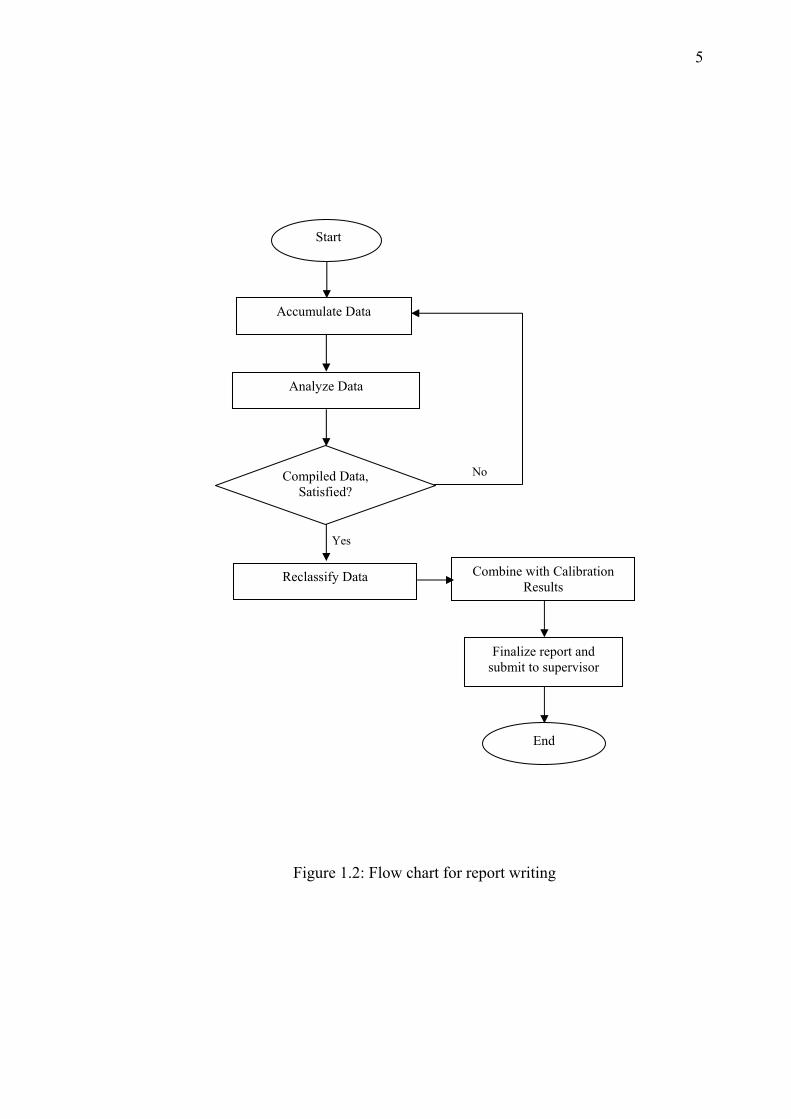
1.4 Project Methodology
This project generally is divided into two major parts which consists of report
writing and the experimental testing approach or test-bed development which is
illustrated by Figure 1.2 and Figure 1.3 respectively. Before preceding any progress
of this project, the data, which is related to this scope, had been collected from time
to time. All the data has been analyzed in order to produce the useful information for
report writing later on. Consequently, with all the information available has been
arranged accordingly. The final step before finalizing the report is to combine the
experimental results to enhanced readability of the report.
The second part of the flow chart is illustrated by Figure 1.3 above. Firstly,
obtain the specific data of MEASAT satellite in terms of EIRP (Effective Isotropic
Radiation Power), operating frequency for DBS application, footprint coverage in
Malaysia. All this data can be obtained directly from internet or the company in
charge because all the specification is fixed. Secondly, performing the investigation
of flat antenna parameters will be carried out in laboratory particularly obtaining the
VSWR, radiation pattern, gain, and beamwidth. These data are required for
calibrating process whether the specification of flat antenna is matched with the
criteria of satellite before developing the test-bed for DBS application. After all
requirements are ready, the test-bed of the DBS application is being developed for
the performance study of flat antenna in DBS application. All the measurement
results will be recorded and reclassify if necessary to make readability and will be
compared with the market antenna.
5
Figure 1.2: Flow chart for report writing
Start
Accumulate Data
Analyze Data
Compiled Data, Satisfied?
No
Reclassify Data
End
Yes
Combine with Calibration Results
Finalize report and submit to supervisor

6
Figure 1.3: Flow chart for calibration device DBS Application
Start
Survey the specification of satellite
Determine specification of antenna
Laboratory Experimentobtain the parameters
Observe the physical layout
antenna
Test-bed for Calibrating DBS
setup
Satisfied?
No
Yes
Verification results
recorded
End

7
1.5 Thesis Outlines
This thesis is organized into 5 chapters to cover completely the research work
for this specific title entitled the performance study of flat antenna in DBS
application.
In Chapter 1, some background and history of flat antenna technology,
especially in DBS application, have been covered briefly. Besides, the author also
includes the project objectives and project scope of doing this thesis. Lastly, the
flow chart which shows how to carry out the work task also has been included in this
chapter.
Some research and reading of the general characteristics of the antenna has
been discussed in the Chapter 2 which is related to the parameter of the
measurements later. Apart from that, the function of satellite subsystem had been
discussed. Besides, the general layout for DBS also has been discussed in this
chapter as well.
Chapter 3 presents the laboratory investigation of RLSA antenna. Through
this chapter, author has included the procedure how to perform the measurement by
using the specific device which is available in the Wireless Communication Centre
(WCC) particularly return loss measurement, VSWR measurement and radiation
measurement. The results for the measurement will discussed at the end of this
chapter in order to evaluate the performance of RLSA antenna.
Chapter 4 discusses the development of the test bed for DBS application.
From this chapter, author will briefly describe which component is needed to
establish the test bed for DBS application. Besides, the function of each component
will be explained in this chapter. Lastly, the performance study of the test bed from
conventional and the RLSA antenna will be evaluated in this chapter.
As a conclusion, all work tasks has been summarized and will be discussed
and the future work also has been included to enhance the recent work.

93
REFERENCES
[1] A.I.Zagghoul, R.K. Gupta, E.C. Kohls, L.Q. Sun & R.M. Allnutt, “Low Cost
Flat Antenna for Commercial & Military SATCOM Terminals,” Lockheed
Martin Global Telecommunications (LMGT) Systems & Technology
Clarksburg, MD.
[2] LIM TIEN SZE, “Linearly Polarised Radial Line Slot Array Antenna
Radiation Pattern Modelling & Test-Bed Development for Direct Broadcast
Satellite,” Universiti Teknologi Malaysia.
[3] Mazlan Othman, “Space Application Development in Malaysia,” National
Space Agency in Malaysia, 14 January 2004.
[4] “TV Reception Solution,” Stallions Satellite and Antenna,
http://www.tvantenna.com/support/tutorials/lnbs.html
[5] “MEASAT Satellite Specification,” MEASAT Satellite System Sdn Bhd,
http://www. measat.com.
[6] David M. Pozar, “Microwave Engineering, Second Edition,” John Wiley &
Sons, Inc. 1998.
[7] K.C. Kelly (March 1957). “Recent Annular Slot Array Experiments.” IRE
National convention Record. Vol 5, Part 1, 144-151.
[8] F.J. Goebles, Jr. K.C. (July 1961), “Arbitrary Polarization from Annular
Planar Antenna.” IRE Trans. On Antennas and Propagation, Vol. AP-9, 342-
349.

94
[9] K.C. Kelly, F.J. Goebles, JR (July 1964), “Annular Slot Monopulse Antenna
Array.” IEEE Trans, Antennas and Propagation, Vol AP-12, 391-403.
[10] N. Goto, M. Yamamoto (August 1980), “Circularly Polarized Radial Line
Slot Antennas.” IEEE Technical Report, AP 89-54, 43.
[11] M. Takahashi, J. Takada, M. Ando, N. Goto (October 1989), “A Single-
Layered Radial Slot Line Slot Antenna.” IEEE Technical Report, AP 89-54.
[12] D.Jefferies, “Antenna”
http://www.ee.surrey.ac.uk/Personal/D.Jeffries/antenna.html (current August
2003)
[13] SkyCross, “Antenna Terminology”
http://www.skycross.com (current August 2003)
[14] Moteco Group Website, “Antenna Basics”
http://www.moteco.com (current July 2003)
[15] Dennis Roddy, “Microwave Tehcnology,” Prentice-Hall, 1986, pp. 405-414.
[16] Allan W.Scott, “Understanding Mircowave,” John Wiley & Sons, Inc, 1993.
[17] Bruce R. Elbert, “The Satellite Communication Applications Handbook,”
ARTECH HOUSE, INC, 1997.
[18] M. RICHHARIA, “SATELLITE COMMUNICATIONS SYSTEMS DESIGN
PRINCIPLES,” THE MACMILLAN PRESS LTD, 1st published 1995.
[19] G. MARAL, M. BOUSQUET, “Satellite Communications Systems,” JOHN
WILEY & SONS, Second Edition 1993.
[20] James Wood, “SATELLITE COMMUNICATIONS POCKET BOOK,”
OXFORD BOSTON JOHANNESBURG, Revised edition 1996.

95
[21] B. G. Evans, “SATELLITE COMMUNICATION SYSTEMS,” The Institution
of Electrical Engineers, London, United Kingdom, 3rd edition, 2000.
[22] Stephenson D. J. “Newnes Guide to Satellite TV: Installation, Reception and
Repair,” Butterworth-Heinemann LTd., Oxford, Great Britain, 1994.
[23] WARREN L. STUTZMAN, GRARY A. THIELE “ANTENNA THOERY
AND DESIGN,”JOHN WILEY & SONS, INC, Second edition, 1998.