Embed Size (px)
Citation preview

Tech Bulletin Page 490-10
RESILIENT SEATED BUTTERFLY VALVES
www.maxsealinc.com
As a part of the Flo-Tite Group, Max-Seal Concentric Butterfly Valves are backed by the resources and experience of over thirty five years of process valve and automation experience.
Available in Wafer and Lug StylesButterfly Valves Designed for Automation & Demanding Manual Applications
Tech Bulletin Page 490C-10
This brochure is general in nature and manufacturer reserves the right to alter dimensions, materials or to make design improvements
P.O. Box 1293Lumberton, NC 28359
Website: www.maxsealinc.com
Max-Seal, Inc.305 East 21st Street
Lumberton, NC 28358
Tel: (910) 738-8904Fax: (910) 738-9112
E-Mail: [email protected]
Lever-Lock 10 Position Type Handle
SEAT TEMPERATURE RANGE
MAX SEAL Models 51, 52 CV Value
Streamlined Disc Design Reduces Pressure Drop and Maximizes Cv
Performance Series Torque Valve
ACTUATOR MOUNTING
Gear Operator
PERFORMANCE SERIES
Models:Wafer 51Lug 52Size Range2” thru 36”Pressure Rating200 WOG250 WOG - optional
Ductile Iron Body, RuggedHeavy Duty ConstructionHigh Quality Epoxy Coating forExcellent Corrosion Resistance2-Piece Stem Design Allows forEasy Assembly and Maintenancewith High Flow Capacity
hANDLE AND gEAR opERAToR DImENSIoNS
VALVE FLoW CoEFFICIENTS & TEChNICAL DATA
SIZE 2” 2.5” 3” 4” 5” 6” 8” 10” 12”
H 5.19 5.84 6.16 7.25 7.38 7.94 11.19 12.97 13.56
A 10.5 10.5 10.5 10.5 10.5 10.5 14 14 20
Material Temperature Range
Buna-N (NBR) 0° to 200°F
EPDM -40° to 275°F
VITON 0° to 275°F
Neoprene -60° to 200°F
Hypalon -40° to 250°F
Silicon -70 to 425°F
PTFE -10° to 260°F
SIZE 2” 2.5” 3” 4” 5” 6” 8” 10” 12” 14” 16” 18” 20” 24”
H 5.41 6.07 6.38 7.48 7.60 8.16 11.13 12.91 13.45 16.13 18.27 21.42 21.42 24.92
F 5.9 5.9 5.9 5.9 5.9 5.9 11.8 11.8 11.8 11.8 11.8 11.8 11.8 15.35
A 6 6 6 6 6 6 9.84 9.84 9.84 10.94 10.94 10.94 10.94 12.05
Max-Seal Valves Are Ideally Suited for Actuated Applications
Max-Seal Offers A broad line of automation systems for precise proportioning or on-off control in either pneumatic or electrically powered units.
Cast Mounting Flange Accommodates All Types of Operators, offering two sets of slotted bolted circles ISO5211 and industry popular type. It is designed to accept direct actuator mounting, some sizes may require a spacer plate.
These wet seating torque valves are figured for wet service defined as lubricated with clean non-abrasive line media
SIZE Angle of Opening
INCH MM 10° 20° 30° 40° 50° 60° 70° 80° 90°
2 50 0.1 5 12 24 45 64 90 125 135
2 1/2 65 0.2 8 20 37 65 98 144 204 220
3 80 0.3 12 22 39 70 116 183 275 302
4 100 0.5 17 36 78 139 230 364 546 600
5 125 0.8 29 61 133 237 392 620 930 1022
6 150 2 45 95 205 366 605 958 1437 1579
8 200 3 89 188 408 727 1202 1903 2854 3136
10 250 4 151 320 694 1237 2047 3240 4859 5340
12 300 5 234 495 1072 1911 3162 5005 7505 8250
SIZE Pressure Differential
INCH MM 50 psi 100 psi 200 psi
2 50 127 147 170
2 1/2 65 135 168 193
3 80 206 225 259
4 100 350 387 445
5 125 525 605 646
6 150 825 997 1147
8 200 1495 1864 2144
10 250 2420 3140 3611
12 300 3612 4767 5482
www.maxsealinc.com www.maxsealinc.com
Tech Bulletin Page 490A-10 Tech Bulletin Page 490B-10BUTTERFLY VALVE - CompoNENTS/DESIgN FEATURES DImENSIoNS / TEChNICAL DATA
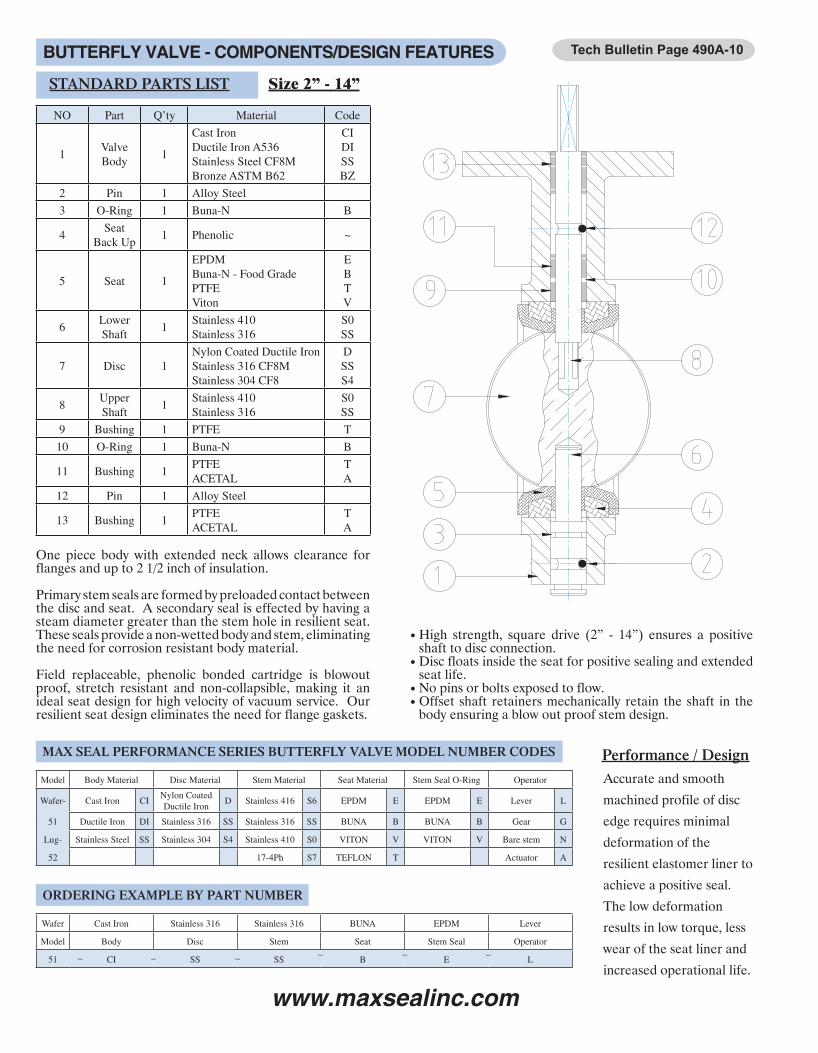
NO Part Q’ty Material Code
1ValveBody
1
Cast IronDuctile Iron A536Stainless Steel CF8MBronze ASTM B62
CIDISSBZ
2 Pin 1 Alloy Steel
3 O-Ring 1 Buna-N B
4Seat
Back Up1 Phenolic ~
5 Seat 1
EPDMBuna-N - Food GradePTFEViton
EBTV
6Lower Shaft
1Stainless 410Stainless 316
S0SS
7 Disc 1Nylon Coated Ductile IronStainless 316 CF8MStainless 304 CF8
DSSS4
8UpperShaft
1Stainless 410Stainless 316
S0SS
9 Bushing 1 PTFE T
10 O-Ring 1 Buna-N B
11 Bushing 1PTFEACETAL
TA
12 Pin 1 Alloy Steel
13 Bushing 1PTFEACETAL
TA
STANDARD PARTS LIST
MAX SEAL PERFORMANCE SERIES BUTTERFLY VALVE MODEL NUMBER CODES
ORDERING EXAMPLE BY PART NUMBER
Size 2” - 14”
One piece body with extended neck allows clearance for flanges and up to 2 1/2 inch of insulation.
Primary stem seals are formed by preloaded contact between the disc and seat. A secondary seal is effected by having a steam diameter greater than the stem hole in resilient seat. These seals provide a non-wetted body and stem, eliminating the need for corrosion resistant body material.
Field replaceable, phenolic bonded cartridge is blowout proof, stretch resistant and non-collapsible, making it an ideal seat design for high velocity of vacuum service. Our resilient seat design eliminates the need for flange gaskets.
High strength, square drive (2” - 14”) ensures a positive shaft to disc connection.Disc floats inside the seat for positive sealing and extended seat life.No pins or bolts exposed to flow.Offset shaft retainers mechanically retain the shaft in the body ensuring a blow out proof stem design.
Accurate and smooth
machined profile of disc
edge requires minimal
deformation of the
resilient elastomer liner to
achieve a positive seal.
The low deformation
results in low torque, less
wear of the seat liner and
increased operational life.
Note:Verify mounting dimensions beforemanufacturing mounting hardware
•
•
••
Performance / DesignModel Body Material Disc Material Stem Material Seat Material Stem Seal O-Ring Operator
Wafer- Cast Iron CINylon CoatedDuctile Iron
D Stainless 416 S6 EPDM E EPDM E Lever L
51 Ductile Iron DI Stainless 316 SS Stainless 316 SS BUNA B BUNA B Gear G
Lug- Stainless Steel SS Stainless 304 S4 Stainless 410 S0 VITON V VITON V Bare stem N
52 17-4Ph S7 TEFLON T Actuator A
Wafer Cast Iron Stainless 316 Stainless 316 BUNA EPDM Lever
Model Body Disc Stem Seat Stem Seal Operator
51 CI SS SS B E L– – – – – –
ANSI Class 125 Concentric Butterfly Valves
Larger sizes available through 120”, consult factoryPressure Ratings:2”-12” 200 psi; 14”-24” 175 psiLug Body for Dead End Service:2”-12”, 150 psi; 14”-24” 125 psiOptional 250 WOGwith 17-4Ph stem & seat modificationVacuum Service up to 28” HgMax-Seal valves are designed for bubble tight shutoff ineither direction of flow. Each valve is factory tested to110% of their pressure rating.
Blow out proof stem designA heavy duty butterfly valve, designed for ANSI Class 125/150 flanges. These valves comply with MSS-SP25, MSS-SP67 and API609 specifications, as well as meeting the requirements of MIL-V-22133C (ship) Type 1, Class A-DPositive Valve Position: When the handle is perpendicular to the pipe, the valve is shut. When the handle is parallel to the pipe, the valve is fully open. The orientation of the disc is indicated by a groove at the shaft end that is in line with the disc.
••
•
•
••
••
•
Max-Seal Performance Series offers longer service life, greater reliability,ease of parts replacement and interchangeability of components.
SizeD E L H1 H2 H3 F G K
Flange Dimension Mounting Base Weight, lbinch mm C T n C1 h1 C2 h2 ISO wafer lug
2 50 4.125 6.00 1.656 3.00 3.94 1.25 4.0 0.50 0.354 4.75 5/8-11unc 4 3.25 0.41 2.76 0.39 F07 5.19 10.5
2.5 65 4.875 7.00 1.75 3.34 4.59 1.25 4.0 0.50 0.354 5.50 5/8-11unc 4 3.25 0.41 2.76 0.39 F07 5.84 10.5
3 80 5.375 7.50 1.78 3.6 4.91 1.25 4.0 0.50 0.354 6.00 5/8-11unc 4 3.25 0.41 2.76 0.39 F07 6.16 10.5
4 100 6.875 9.00 2.05 4.28 6.00 1.25 4.0 0.625 0.433 7.50 5/8-11unc 8 3.25 0.41 2.76 0.39 F07 7.25 10.5
5 125 7.75 10.0 1.13 4.84 6.13 1.25 4.0 0.75 0.55 8.50 3/4-10unc 8 3.25 0.41 2.76 0.39 F07 7.38 10.5
6 150 8.75 11.0 2.19 5.34 6.69 1.25 4.0 0.75 0.55 9.50 3/4-10unc 8 3.25 0.41 2.76 0.39 F07 7.94 10.5
8 200 11.00 13.5 2.38 6.53 9.44 1.75 6.0 0.875 0.67 11.75 3/4-10unc 8 5.00 0.53 4.01 0.47 F10 11.2 14
10 250 13.38 16.0 2.58 7.84 11.22 1.75 6.0 1.125 0.87 14.25 7/8-9unc 12 5.00 0.53 4.01 0.47 F10 13.0 14
12 300 16.13 19.0 3.03 9.38 11.81 1.75 6.0 1.25 0.87 17.00 7/8-9unc 12 5.00 0.53 4.01 0.47 F10 13.6 20
14 350 17.16 20.63 3.07 10.5 14.49 1.77 6.0 1.24 0.87 18.75 1-8unc 12 5.00 0.53 4.01 0.47 F10 41.3 56
16 400 19.21 23.18 4.02 12.16 15.75 2.83 7.76 1.49 0.39x1.42 21.25 1-8unc 16 n/a n/a 5.51 0.71 F14 61 96
18 450 21.22 25.00 4.49 12.91 16.61 2.83 7.76 1.69 0.39x1.61 22.75 1 1/8-8unc 16 n/a n/a 5.51 0.71 F14 79 122
20 500 23.35 27.72 5.00 14.21 18.9 2.83 7.76 1.80 0.47x1.74 25.00 1 1/8-8unc 20 n/a n/a 5.51 0.71 F14 128 202
24 600 32.44 32.68 6.06 18.07 22.12 3.23 10.87 2.13 0.63x2.15 29.50 1 1/4-8unc 20 n/a n/a 6.50 0.87 F16 188 270

www.maxsealinc.com www.maxsealinc.com
Tech Bulletin Page 490A-10 Tech Bulletin Page 490B-10BUTTERFLY VALVE - CompoNENTS/DESIgN FEATURES DImENSIoNS / TEChNICAL DATA
NO Part Q’ty Material Code
1ValveBody
1
Cast IronDuctile Iron A536Stainless Steel CF8MBronze ASTM B62
CIDISSBZ
2 Pin 1 Alloy Steel
3 O-Ring 1 Buna-N B
4Seat
Back Up1 Phenolic ~
5 Seat 1
EPDMBuna-N - Food GradePTFEViton
EBTV
6Lower Shaft
1Stainless 410Stainless 316
S0SS
7 Disc 1Nylon Coated Ductile IronStainless 316 CF8MStainless 304 CF8
DSSS4
8UpperShaft
1Stainless 410Stainless 316
S0SS
9 Bushing 1 PTFE T
10 O-Ring 1 Buna-N B
11 Bushing 1PTFEACETAL
TA
12 Pin 1 Alloy Steel
13 Bushing 1PTFEACETAL
TA
STANDARD PARTS LIST
MAX SEAL PERFORMANCE SERIES BUTTERFLY VALVE MODEL NUMBER CODES
ORDERING EXAMPLE BY PART NUMBER
Size 2” - 14”
One piece body with extended neck allows clearance for flanges and up to 2 1/2 inch of insulation.
Primary stem seals are formed by preloaded contact between the disc and seat. A secondary seal is effected by having a steam diameter greater than the stem hole in resilient seat. These seals provide a non-wetted body and stem, eliminating the need for corrosion resistant body material.
Field replaceable, phenolic bonded cartridge is blowout proof, stretch resistant and non-collapsible, making it an ideal seat design for high velocity of vacuum service. Our resilient seat design eliminates the need for flange gaskets.
High strength, square drive (2” - 14”) ensures a positive shaft to disc connection.Disc floats inside the seat for positive sealing and extended seat life.No pins or bolts exposed to flow.Offset shaft retainers mechanically retain the shaft in the body ensuring a blow out proof stem design.
Accurate and smooth
machined profile of disc
edge requires minimal
deformation of the
resilient elastomer liner to
achieve a positive seal.
The low deformation
results in low torque, less
wear of the seat liner and
increased operational life.
Note:Verify mounting dimensions beforemanufacturing mounting hardware
•
•
••
Performance / DesignModel Body Material Disc Material Stem Material Seat Material Stem Seal O-Ring Operator
Wafer- Cast Iron CINylon CoatedDuctile Iron
D Stainless 416 S6 EPDM E EPDM E Lever L
51 Ductile Iron DI Stainless 316 SS Stainless 316 SS BUNA B BUNA B Gear G
Lug- Stainless Steel SS Stainless 304 S4 Stainless 410 S0 VITON V VITON V Bare stem N
52 17-4Ph S7 TEFLON T Actuator A
Wafer Cast Iron Stainless 316 Stainless 316 BUNA EPDM Lever
Model Body Disc Stem Seat Stem Seal Operator
51 CI SS SS B E L– – – – – –
ANSI Class 125 Concentric Butterfly Valves
Larger sizes available through 120”, consult factoryPressure Ratings:2”-12” 200 psi; 14”-24” 175 psiLug Body for Dead End Service:2”-12”, 150 psi; 14”-24” 125 psiOptional 250 WOGwith 17-4Ph stem & seat modificationVacuum Service up to 28” HgMax-Seal valves are designed for bubble tight shutoff ineither direction of flow. Each valve is factory tested to110% of their pressure rating.
Blow out proof stem designA heavy duty butterfly valve, designed for ANSI Class 125/150 flanges. These valves comply with MSS-SP25, MSS-SP67 and API609 specifications, as well as meeting the requirements of MIL-V-22133C (ship) Type 1, Class A-DPositive Valve Position: When the handle is perpendicular to the pipe, the valve is shut. When the handle is parallel to the pipe, the valve is fully open. The orientation of the disc is indicated by a groove at the shaft end that is in line with the disc.
••
•
•
••
••
•
Max-Seal Performance Series offers longer service life, greater reliability,ease of parts replacement and interchangeability of components.
SizeD E L H1 H2 H3 F G K
Flange Dimension Mounting Base Weight, lbinch mm C T n C1 h1 C2 h2 ISO wafer lug
2 50 4.125 6.00 1.656 3.00 3.94 1.25 4.0 0.50 0.354 4.75 5/8-11unc 4 3.25 0.41 2.76 0.39 F07 5.19 10.5
2.5 65 4.875 7.00 1.75 3.34 4.59 1.25 4.0 0.50 0.354 5.50 5/8-11unc 4 3.25 0.41 2.76 0.39 F07 5.84 10.5
3 80 5.375 7.50 1.78 3.6 4.91 1.25 4.0 0.50 0.354 6.00 5/8-11unc 4 3.25 0.41 2.76 0.39 F07 6.16 10.5
4 100 6.875 9.00 2.05 4.28 6.00 1.25 4.0 0.625 0.433 7.50 5/8-11unc 8 3.25 0.41 2.76 0.39 F07 7.25 10.5
5 125 7.75 10.0 1.13 4.84 6.13 1.25 4.0 0.75 0.55 8.50 3/4-10unc 8 3.25 0.41 2.76 0.39 F07 7.38 10.5
6 150 8.75 11.0 2.19 5.34 6.69 1.25 4.0 0.75 0.55 9.50 3/4-10unc 8 3.25 0.41 2.76 0.39 F07 7.94 10.5
8 200 11.00 13.5 2.38 6.53 9.44 1.75 6.0 0.875 0.67 11.75 3/4-10unc 8 5.00 0.53 4.01 0.47 F10 11.2 14
10 250 13.38 16.0 2.58 7.84 11.22 1.75 6.0 1.125 0.87 14.25 7/8-9unc 12 5.00 0.53 4.01 0.47 F10 13.0 14
12 300 16.13 19.0 3.03 9.38 11.81 1.75 6.0 1.25 0.87 17.00 7/8-9unc 12 5.00 0.53 4.01 0.47 F10 13.6 20
14 350 17.16 20.63 3.07 10.5 14.49 1.77 6.0 1.24 0.87 18.75 1-8unc 12 5.00 0.53 4.01 0.47 F10 41.3 56
16 400 19.21 23.18 4.02 12.16 15.75 2.83 7.76 1.49 0.39x1.42 21.25 1-8unc 16 n/a n/a 5.51 0.71 F14 61 96
18 450 21.22 25.00 4.49 12.91 16.61 2.83 7.76 1.69 0.39x1.61 22.75 1 1/8-8unc 16 n/a n/a 5.51 0.71 F14 79 122
20 500 23.35 27.72 5.00 14.21 18.9 2.83 7.76 1.80 0.47x1.74 25.00 1 1/8-8unc 20 n/a n/a 5.51 0.71 F14 128 202
24 600 32.44 32.68 6.06 18.07 22.12 3.23 10.87 2.13 0.63x2.15 29.50 1 1/4-8unc 20 n/a n/a 6.50 0.87 F16 188 270

Tech Bulletin Page 490-10
RESILIENT SEATED BUTTERFLY VALVES
www.maxsealinc.com
As a part of the Flo-Tite Group, Max-Seal Concentric Butterfly Valves are backed by the resources and experience of over thirty five years of process valve and automation experience.
Available in Wafer and Lug StylesButterfly Valves Designed for Automation & Demanding Manual Applications
Tech Bulletin Page 490C-10
This brochure is general in nature and manufacturer reserves the right to alter dimensions, materials or to make design improvements
P.O. Box 1293Lumberton, NC 28359
Website: www.maxsealinc.com
Max-Seal, Inc.305 East 21st Street
Lumberton, NC 28358
Tel: (910) 738-8904Fax: (910) 738-9112
E-Mail: [email protected]
Lever-Lock 10 Position Type Handle
SEAT TEMPERATURE RANGE
MAX SEAL Models 51, 52 CV Value
Streamlined Disc Design Reduces Pressure Drop and Maximizes Cv
Performance Series Torque Valve
ACTUATOR MOUNTING
Gear Operator
PERFORMANCE SERIES
Models:Wafer 51Lug 52Size Range2” thru 36”Pressure Rating200 WOG250 WOG - optional
Ductile Iron Body, RuggedHeavy Duty ConstructionHigh Quality Epoxy Coating forExcellent Corrosion Resistance2-Piece Stem Design Allows forEasy Assembly and Maintenancewith High Flow Capacity
hANDLE AND gEAR opERAToR DImENSIoNS
VALVE FLoW CoEFFICIENTS & TEChNICAL DATA
SIZE 2” 2.5” 3” 4” 5” 6” 8” 10” 12”
H 5.19 5.84 6.16 7.25 7.38 7.94 11.19 12.97 13.56
A 10.5 10.5 10.5 10.5 10.5 10.5 14 14 20
Material Temperature Range
Buna-N (NBR) 0° to 200°F
EPDM -40° to 275°F
VITON 0° to 275°F
Neoprene -60° to 200°F
Hypalon -40° to 250°F
Silicon -70 to 425°F
PTFE -10° to 260°F
SIZE 2” 2.5” 3” 4” 5” 6” 8” 10” 12” 14” 16” 18” 20” 24”
H 5.41 6.07 6.38 7.48 7.60 8.16 11.13 12.91 13.45 16.13 18.27 21.42 21.42 24.92
F 5.9 5.9 5.9 5.9 5.9 5.9 11.8 11.8 11.8 11.8 11.8 11.8 11.8 15.35
A 6 6 6 6 6 6 9.84 9.84 9.84 10.94 10.94 10.94 10.94 12.05
Max-Seal Valves Are Ideally Suited for Actuated Applications
Max-Seal Offers A broad line of automation systems for precise proportioning or on-off control in either pneumatic or electrically powered units.
Cast Mounting Flange Accommodates All Types of Operators, offering two sets of slotted bolted circles ISO5211 and industry popular type. It is designed to accept direct actuator mounting, some sizes may require a spacer plate.
These wet seating torque valves are figured for wet service defined as lubricated with clean non-abrasive line media
SIZE Angle of Opening
INCH MM 10° 20° 30° 40° 50° 60° 70° 80° 90°
2 50 0.1 5 12 24 45 64 90 125 135
2 1/2 65 0.2 8 20 37 65 98 144 204 220
3 80 0.3 12 22 39 70 116 183 275 302
4 100 0.5 17 36 78 139 230 364 546 600
5 125 0.8 29 61 133 237 392 620 930 1022
6 150 2 45 95 205 366 605 958 1437 1579
8 200 3 89 188 408 727 1202 1903 2854 3136
10 250 4 151 320 694 1237 2047 3240 4859 5340
12 300 5 234 495 1072 1911 3162 5005 7505 8250
SIZE Pressure Differential
INCH MM 50 psi 100 psi 200 psi
2 50 127 147 170
2 1/2 65 135 168 193
3 80 206 225 259
4 100 350 387 445
5 125 525 605 646
6 150 825 997 1147
8 200 1495 1864 2144
10 250 2420 3140 3611
12 300 3612 4767 5482