Embed Size (px)
Citation preview

PERFORMANCE OF TEST EMBANKMENTCONSTRUCTED TO FAILURE ON SOFT MARINE CLAY
By B. Indraratna,' Member, ASCE, A. S. Balasubramaniam,'Fellow, ASCE, and S. Balachandran3
ABSTRACT: This paper describes the observed and the predicted performance ofa full-scale trial embankment built to failure on a soft Malaysian marine clay.Predictions of the subsoil deformation. the critical height of fill and the corrc-sponding slip surface are made and subsequently compared to the field measure-ments. It is of importance to realize that all the predictions were made prior to theactual failure of the embankment. The comparison with measurements was possibleonly after the International Symposium on Trial Embankments on Malaysian Ma-rine Clays, was held in Kuala Lumpur, Malaysia, in November 1989, during whichthe field data were made available to the invited predictors (including the secondwriter) by the Malaysian Highway Authority. Finite-element codes based on themodified Cam-clay theory (CRISP) and hyperbolic stress-strain model (ISBILD)were utilized to investigate the behavior of the embankment and the foundationsoil until failure. The type of numerical modeling includes purely undrained, fullydrained. and a coupled consolidation analysis. The finite-clement solutions aresubsequently compared with the conventional stability analy.sis.
INTRODUCTION
The rapid-development strategies and the associated urbanization in cer-tain parts of Malaysia have compelled engineers to construct earth structuressuch as embankments and major highways over soft clay deposits havinglow bearing capacities coupled with excessive settlement characteristics. InSoutheast Asia soft clays are fairly widespread, and some of these depositsexist extensively in the vicinity of capital cities. The construction of theMalaysian North-South Expressway across the Muar plain has met formi-dable obstacles (instability) where a significant part of the expressway crossesover 10-20 m of thick soft clay deposits characterized by low undrainedshear strengths and high water contents. Furthermore, ground subsidenceassociated with the consolidation of soft clay deposits also pose considerablethreats to surface structures.
To investigate in detail the behavior of Muar clay deposits, the MalaysianHighway Authority recently selected an appropriate site on the Muar plainto construct several full-scale test embankments, with one built to failure.The clays along the west coast of Peninsular Malaysia constitute a coastalplain marine clay up to 20 m thick, with an average lateral extent of about25 km. The site of the test embankment is located about 20 km inland fromMuar and 50 km due east of Malacca on the southwest coast of Malaysia(Fig. 1). The subsurface geology data at the site reveal the existence of a
'Lec., Dept. of Civ. and Mining Engrg., Univ. of Wollongong, P.O. Box 1144(Northfields Ave.), Wollongong, NSW 2500, Australia.
2prof., Div. of Geotech. Engrg., Asian Inst. of Tech., G.P.O. Box 2754. Bangkok,Thailand.
3Grad. Student, Univ of Cambridge, Cambridge, CB2 1ST England.Note. Discussion open until June 1, 1992. To extend the closing date one month.
a written request must be filed with the ASCE Manager of Journals. The manuscriptfor this paper was submitted for review and possible publication on January 7, 1991.This paper is part of the Journal of Geotechnical Engineering, Vol. 118, No.1,January, 1992. ~ASCE, ISSN 0733-9410/92/0001-0012/$1.00 + $.15 per page. PaperNo. 1215.

07
~
weathered crust of about 2.0 m thick above a 16.5 m thick layer of soft siltyclay. The latter layer can be further divided into an upper very soft and alower soft silty clay. Immediately beneath this lower clay layer is a 0.3-0.5m thick peaty soil followed by a stiff sandy clay. The clayey succession endsat a dense sand layer at about 22.5 m below ground level. Although manysoft clays encountered in the Southeast Asian countries are generally nor-mally consolidated, they may exhibit light overconsolidation caused by sur-face desiccation and weathering. The apparent overconsolidation ratio (OCR)of such a clay can be as high as 2.5, and this influences its preconsolidationpressure and undrained strength (Bjerrum 1973).
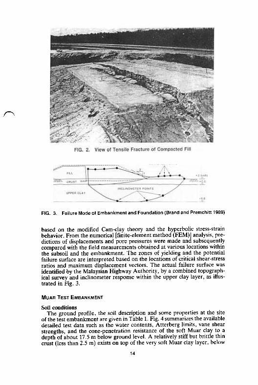
The embankment raised on this soft Muar clay formation failed by thedevelopment of a "quasi slip circle" type of rotational failure at a criticalheight of approximately 5.5 m. with a pronounced tension crack propagatingvertically through the crust and the fill (Figs. 2 and 3), This paper elucidatesthe predicted behavior of the soft Muar clay foundation with regard to thecritical height of embankment at failure, excess pore pressures, lateral andvertical displacements (including heave), as well as an attempt to proposea conceivable failure mode. The predictions are made on the basis of severaldeformation analyses incorporating two different constitutive soil models,
13
(\
FIG. 3. Failure Mode of Embankment and Foundation (Brand and Premchitt 1989)
based on the modified Cam-clay theory and the hyperbolic stress-strainbehavior. From the numerical [finite-element method (FEM)] analysis, pre-dictions of displacements and pore pressures were made and subsequentlycompared with the field measurements obtained at various locations withinthe subsoil and the embankment. The zones of yielding and the potentialfailure surface are interpreted based on the locations of critical shear-stressratios and maximum displacement vectors. The actual failure surface wasidentified by the Malaysian Highway Authority, by a combined topograph-ical survey and inclinometer response within the upper clay layer, as illus-trated in Fig. 3.
MUAR TEST EMBANKMENT
Soil conditionsThe ground profile, the soil description and some properties at the site
of the test embankment are given in Table 1. Fig. 4 summarizes the availabledetailed test data such as the water contents, Atterberg limits, vane shearstrengths, and the cone-penetration resistance of the soft Muar clay to adepth of about 17.5 m below ground level. A relatively stiff but brittle thincrust (less than 2.5 m) exists on top of the very soft Muar clay layer, below
14

c:-B
>-
.c c:
C:.!G
~>
-,g-m
~c:m
u..~
OJ-..~
-E
~E
X=
oE
OJ
~0
-0;T
"
~I~reCii
c~,., "6 .
-i!;-E
S-o:
-O
J co.c (J
13°'" ~
OJ-
-tjOJ-""'o.
~oE
e-
o.c~
-0
~ c -
0 ,,°
- I
~ .g + ~I
~IU_~ c.~- E 0
(~ ~
c:0 ,
'=...
to -
"".,--=
~tO
~O
:Ja-~"""~
-c:"'-0
.,u
~.,
0-Il:.co.E
~~
_:::. -"G;
>-
m=
t'5~
"Cc-m"
(/)-
=-
.- C
D(/)-
~-
;;!!J.(;;'1
ff
1'0;~u
II I ~
I ~
I'" 10
tl I::;
I ~
>-
'"ug,Q
.~
J:i J:i
'2 2
So
So
"2 '::
:!. 0
:!. ~
'2 e
N
'2 e
,- - ,-
,- - ,tJ
- = ,,"-
- = "
"-0
0-'"
00
-'"'"
~
=
'" ~
=
~e::","
~e::.,.
~ r:!
'" '"' ~sx.. VI
00;
~
;.,'""iJ~..J 0,. ~ ,~ .., .Q ~ ~
~~
oC'
~"O
- u
C"
C
' "
~_C
~
C"--
--e
" .-
--0
" u C
oC
..-
~-,
-",oC
u -~
..
~-
~-O
O
~-
~
- 0-
~£
..~~
. ~
"O~
=
~..
u~- --
oC0= >
0 "C
" "
~ oC
0-
u. -
>..-
e-
-c
-" -- =
. 00
~
~ --
~-
~
c" c
'gj, ~
. ~
eO
" .. -- ,,--
:!J c .
... =--
~ ~
~
§ c ~
~] -f
~
g ~ ~
~ ~
E~
; "u~
""'~~
["e
-s §"u""
e~
-
-- C
"0 N
"
- >
, e
c
10.,.
>'"00
e"O
u ~
"0
>,"
e" ~
c-v;";",c_- oc_~
~Q
.~C
'0
OO
:E"
e oC
~
~
; ~
-
~
; -0;
"0 ~
~oC
oC
-~~
-oC~
~
&O
CO
O>
,;c]
'0 -2 6' 0."0
~ -~
g 0
C .;; ~
~ ~
] ~
0 "
~cc.
CO
O
~".O
O
,.-oC
. ~c"
>
00" >
, -- C
0 ~
.c C
>
, '.: .~
.'C
c--
." --"~
,,-- .,.
0 00
~ -- ~
" -
>,
.c"O
oC
>,.
-~
--= =
--:;uJ
'"~
~..O
O"O
..
00,,-":0..>,
~~
O"'
.8C->
'~"'C
" -O
.oCoC
"oe
..- _0'.
".-o;.U
OO
~Q
.. .
"ON
.. ."O
..~O
O~
~
('1
Q"
Q
>-
coU>
-"0=co'"e
e~
~I
~~I
I
~ ~ sXN~ '"' '"
.. ~
"8'"'"
~
~ -

which the water content is as high as 100% and generally exceeds the liquidlimit. The plasticity index generally ranges between 40% and 50%. Theundrained shear strength as measured by the field vane has a minimumvalue of about 8 kPa at a depth of 3 m, and this increases approximatelylinearly with depth. The cone resistance not only indicates a similar trend,but also reflects clearly the influence of the crust (Brand and Premchitt1989). Very little information is available with regard to the thin peaty soillayer (less than 0.5 m thick) at a depth of about 18 m below the groundlevel.
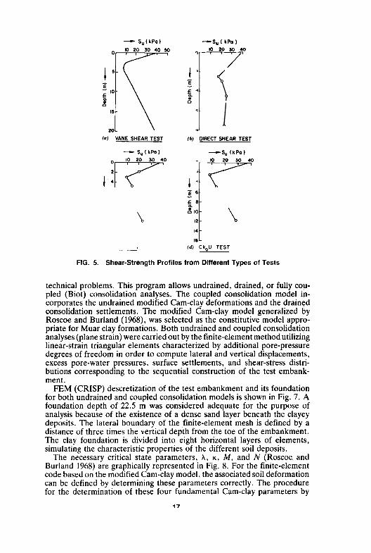
In addition to the extensive in-situ data, a considerable amount of lab-oratory information was acquired for the subsurface clay deposits prior tothe construction of the test embankment. Apart from the determination ofdetailed physical characteristics, extensive laboratory tests were conductedat the Asian Institute of Technology, in Bankok, to measure their engi-neering properties. These include direct shear tests, unconfined compressiontests, unconsolidated undrained (UU) triaxial tests, and consolidated un-drained (CIU) and consolidated drained (CD) triaxial tests. Laboratorypermeability tests and oedometer consolidation tests were also carried out.A summary of the undrained shear-strength profiles and permeability meas-urements are illustrated in Figs. 5 and 6, respectively. Except for the directshear test, the laboratory results closely resemble the field vane shear-strength profile.
The field measurements were used in the numerical analysis after beingsubjected to correction factors suggested by Bjerrum (1973). The undrainedmodulus (Eo) and effective strength parameters (c', <1>'), were also deter-mined from the appropriate triaxial tests, and are summarized in Table 2for the various clay layers. In addition to these routine geotechnical tests,a series of specialized triaxial tests were conducted, including constant stressratio tests, effective and total stress path tests, and anisotropically consol-idated undrained (CU) tests. These tests were intended to provide the mostappropriate modified Cam-clay model parameters (Table 3) for the predic-tion of displacements and pore-pressure changes associated with the variousclay layers beneath the test embankment.
FINITE ELEMENT CODES AND SOIL MODELS
Modified Cam-Clay Model in CRISPCRISP, a critical-state finite-element program developed at Cambridge
University, Cambridge, England, has been used extensiv.ely to analyze geo-
16
--SuI kPa)
10 20 30 40
--r---r7
./~
E~a...0
(6) DIRECT SHEAR TEST
-So (kPO)
~I
\ K) ~ 40
"1-~ '1-
- Su(kPa)
~
E- 10~~.a
15
20(a) VANE SHEAR TEST- Su(kPa)
0
2
~ 4
~ 6
£ 8~~ JO
12
14
16(", UU TEST
!~0.
\ ~:~~ \14
16
---' (d) CkoU TEST
FIG. 5. Shear-Strength Profiles from Different Types of Tests
technical problems. This program allows undrained, drained, or fully cou-pled (Biot) consolidation analyses. The coupled consolidation model in-corporates the undrained modified Cam-clay deformations and the drainedconsolidation settlements. The modified Cam-clay model generalized byRoscoe and Burland (1968), was selected as the constitutive model appro-priate for Muar clay formations. Both undrained and coupled consolidationanalyses (plane strain) were carried out by the finite-element method utilizinglinear-strain triangular elements characterized by additional pore-pressuredegrees of freedom in order to compute lateral and vertical displacements,excess pore-water pressures, surface settlements, and shear-stress distri-butions corresponding to the sequential construction of the test embank-ment.
FEM (CRISP) descretization of the test embankment and its foundationfor both undrained and coupled consolidation models is shown in Fig. 7. Afoundation depth of 22.5 m was considered adequate for the purpose ofanalysis because of the existence of a dense sand layer beneath the clayeydeposits. The lateral boundary of the ,finite-element mesh is defined by adistance of three times the vertical depth from the toe of the embankment.The clay foundation is divided into eight horizontal layers of elements,simulating the characteristic properties of the different soil deposits.
The necessary critical state parameters, A, K, M, and N (Roscoe andBurland 1968) are graphically represented in Fig. 8. For the finite-elementcode based on the modified Cam-clay model. the associated soil deformationcan be defined by determining these parameters correctly. The procedurefor the determination of these four fundamental Cam-clay parameters by
17

E
~Q."0
FIG. 6. Variation of Field and Laboratory Permeability with Depth
TABLE 2. Variation of Shear Strength and Deformation Parameters
Depth(m)(1)
0-22-55-88-11
11-1414-20
c' (kPa)
(3)
814229
1614
Eu (kPa)(2)
25,5006,6008,9339,1206,5935,884
<1>' (degrees)
(4)
12.5147
201721.5
triaxial tests is discussed in detail by Britto and Gunn (1987). For the currentstudy, the magnitude of A is selected in such a manner that the undrainedexperimental stress-strain curve coincides with the undrained predictionsfrom the modified Cam-clay theory.
The values of relevant soil parameters obtained from CKoU tests andemployed in the analysis are summarized in Table 3. The quantity ecs (voidratio at unit P' on an e-ln P' graph) is incorporated instead of N. Thevariations of bulk modulus (Kw), horizontal and vertical permeabilities (Khand K.,) with depth are also given. Because intact undisturbed samples fromthe weathered crust were not recovered for laboratory testing, the Cam-
18

c:-cn~~""Qj"C0
~>-~uE~
U"C
~:c0~
.S"CQ)OJ:>OJQjQ;E~m
Q.
.0cn
co)
W..JIn~I-
I Or) Or) .I:: ~~c.;NQ.~~N~-NG) E=. I I I Io~ o~~~
N~~
,b-~~""
x~
"' "' 0- 0-I I I I
~ 0000"'~ ""'~Ee. xxx x
- """~~... ...
':@'°l""E::.
~ I """'"""O
-<~'"":'"":'"":'"": ,""",~"
"" ~ I 0- 0- r- '"'~~~~~
~ I """'"'cx>o
~~'=!'=!'=!~r--,-,,",,(""'
I r--r "o..O;O;~"!
"-,...",
" $'1 ~ ~ ~ ~-- ,.., c--,-, '""'
19
..,,-r--o~""N-o
,,- ~-
-f«i' I "!"!"!~
?-z-\O"""\O
~
.. .. .. ..I I" 1 10000
X X X X~~.c.cri.-;.-;.-;

10- ' .-""'
"=l~~I-:::;
~ 0:::::17~~~Q- "7 "'-
225m.~~-- W-8- - ., -..~ - d0 8m 20m 40 m 52m '4m 80m
FIG. 7. Finite-Element Discretization of Embankment and Subsoils for CRISP
Analysis
l-/'i" '7
,
N v1
~~ Vkl
vk2'"In (p')
(6)
Lcritical stateiinoY ad'fiOd com-clay yield surface
p: p'
~ p'
Criticstott
(d) J
.,'v
FIG. 8. Critical-State Parameters based on Modified Cam-Clay Model (Britto and
Gunn 1987)
clay properties of this topmost layer are assumed to be the same as thoseobtained for the silty clay layer just beneath it. Since the weathered crustis relatively thin (less than 2.0 m), the errors caused by this assumption areanticipated to be small. In addition to these parameters the in-situ stressconditions are incorporated in the numerical analysis, including the in-situ
20

effective stresses (Ko), isotropic preconsolidation pressure (Pc'), and thevariation of ground-water pressures with depth as summarized in Table 4.The vertical and horizontal permeabilities required for consolidation analysisare interpolated from Fig. 6. For the embankment fill (E = 5,100 kPa;v = 0.3; and "y = 20.5 kN/m3), the shear resistance is represented by c =19 kPa and <1>' = 26°, obtained from laboratory tests.
Nonlinear (Hyperbolic) Stress.Strain Model in ISBILDAs a supplementary analysis, the nonlinear (hyperbolic) finite-element
code, ISBILD (Ozawa and Duncan 1973) is employed. The finite-element-descritization form of the problem applicable for ISBILD is illustrated inFig. 9, in which isoparametric quadrilateral elements are employed. Thestress-strain behavior of a soil depends on a number of different factorsincluding the unit weight, water content, the structure, drainage conditions,loading conditions, duration of loading, and stress history. The soil-defor-mation response over a wide range of stresses is always nonlinear inelastic,and is dependent on the magnitude of the confining pressure applied in thetest. ISBILD was developed on the basis of a hyperbolic (nonlinear) al-gebraic function, which can be an accurate representation of the soil stress-strain behavior if the necessary parameters can be correctly determinedexperimentally.
The assumed stress-strain behavior and the required parameters of thehyperbolic model are defined in Fig. 10. For Muar clay a typical failureratio of 0.86 has been determined from triaxial compression tests. Com-putation of the tangent modulus, Poisson's ratio, and other properties for
'i,
JRiIffiffifEE-od" ..0 8m 20m 30m 4Om 52m 64m 80m
FIG. 9. Finite-Element Discretization of Embankment and Subsoils for ISBILD
Analysis
I i I I I~ II I I I I ! I I I I I I I I
21

:~
~a' b..~
~
at
H,..,bo~
~S"om
C",.J'/
~---~-,,' ,;
FIG. 10. Parameters Required for Hyperbolic Stress-Strain Model (Ozawa andDuncan 1973)
TABLE 5. Soil Parameters Used for Hyperbolic Stress-Strain Model (ISBILD): Un-drained Case
the hyperbolic model is explained in detail by Kulhawy et al. (1969) andOzawa and Duncan (1973). The unloading-reloading modulus number (Kur)is used to evaluate swelling and recompression behavior in addition to themodulus number (K). A summary of soil parameters applicable for un-drained and drained analysis by ISBILD is given in Tables 5 and 6.
FINITE-ELEMENT ANALYSIS
The finite-element method was used to obtain pore-pressure variationsbeneath the embankment, displacements (vertical and lateral), and surfacesettlements during each meter of filling, and for subsequent prediction ofthe failure surface. Shear-stress contours beneath the embankment at failure
22
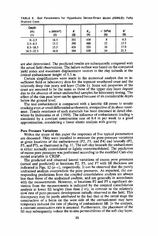
TABLE 6. Soil Parameters for Hyperbolic Stress-Strain Model (ISBILD): FullyDrained Case
are also determined. The predicted results are subsequently compared withthe actual field observations. The failure surface was based on the computedyield zones and maximum displacement vectors in the clay subsoils at thecritical embankment height of 5.5 m.
Certain simplifications were made in the numerical analysis due to in-sufficient field or laboratory data for the topmost weathered crust and therelatively deep thin peaty soil layer (Table 1). Some soil properties of thecrust are assumed to be the same as those of the upper clay layer depositdue to the absence of intact undisturbed samples for laboratory testing. Theeffect of the thin peat layer can be ignored because of its considerable depthbelow the ground level.
The test embankment is compacted with a lateritic fill prone to tensilecracking even at small differential settlements, irrespective of its shear resist-ance. Tensile resistance of such materials has been discussed in detail else-where by lndraratna et al. (1990). The influence of embankment loading issimulated by a constant construction rate of 0.4 m per week to a goodapproximation, considering a linear elastic analysis with gravity.
Pore Pressure VariationsWithin the scope of this paper the responses of five typical piezometers
are discussed. They were installed to measure the pore-pressure variationsat given locations of the embankment (P2, P3, and P4) and laterally (P2,PS, and P7), as illustrated in Fig. 11. The soft clay beneath the embankmentis either normally consolidated or lightly overconsolidated. The predictionof excess pore pressures was performed according to the modified Cam-claymodel available in CRISP.
The predicted and observed lateral variations of excess pore pressures(actual and predicted) at locations P2, PS, and P7 with fill thickness areindicated in Figs. 12 (a-c), respectively. It can be observed that the purelyundrained analysis overpredicts the pore pressures. As expected, the cor-responding predictions from the coupled consolidation analysis are alwaysless than those of the undrained analysis, and are generally in accordancewith the measurements. However, at locations P2 and PS a significant de-viation from the measurements is indicated by the coupled consolidationanalysis at lower fill heights (less than 2 m), in contrast to the relativelyslow rate of pore-pressure development initially observed in the field. Thisdiscrepancy may be partly attributed to the fact that at the initial stage theconstruction of a berm on the west side of the embankment may havetemporary reduced the rate of placing of embankment fill. In the analysis,a constant construction rate is assumed. Furthermore, the placement of thefill may subsequently reduce the in-situ permeabilities of the soft clay layer,
23

LEGEND:v Settlement gauge. Piezometera Inclinometer and
settlement rings+ Heave marker
""""'"
10 30 40m
, I I51 52 53 54
Plate oeillemeni gauge
2 Heave marker~1 H9 H71'2.".,RI fi5 H1
.('OJ~1
. P1~RI/~T
VERY SOFTCLAY
.P2
°P3
SOFT CLA Y. P4 I.~ Pneumatic niezometer
-PEAT
SANDY CLAY
(b) ! 13 U 12 11 SAND
FIG. 11. Plan and Cross Section of Muar Test Embankment Indicating Key In-strumentation
24
;..-
~'~""'4'Thockn... of FoI' 1m)
( 0)
vo~'~~" "'. 6Thickn... of F"' Iml
( cJ
FIG. 12. Lateral Variation of Excess Pore Pressure with Fill Thickness
which in turn would contribute to the higher rate of excess pore-pressuredevelopment in the field. In fact, this behavior might be evident at locationP2 [Fig. 12(a)], as the fill height is raised from 2 m to 4 m.
As expected, the excess pore pressures diminish along the lateral directionwith the decreasing effect of surcharge. At distances farther away from thetoe (at location P7), the discrepancy between the actual and predicted values(coupled analysis) is insignificant at lower fill heights, in contrast to P2 andP5. Particularly at greater depth, the undrained analysis seems to be lessrealistic, probably because the consolidation of soft clay layers is promotedby the existence of sandy clay and medium to coarse sand deposits beyonda depth of 18.5 m from the ground level. On the basis of comparison withthe observations, the coupled consolidation analysis provides a more ac-ceptable solution.
The variations of excess pore pressures beneath the embankment centerare shown in Fig. 13, for fill thickness ranging from 2 m to 5 m. At a fillthickness of 5.5 m, the piezometer readings are not available as a result ofcomplete failure. For fill thickness up to 2 m the undrained predictions aremuch greater than the measured values, whereas the coupled analysis givesa better estimation. In the vicinity of the ground surface, upward drainagecan occur readily, leading to rapid dissipation of the excess pore pressures-.Therefore, at locations near the surface, realistic predictions should onlybe anticipated from the coupled analysis. However, with increased depths,where the dissipation of pore pressures tends to become restrained, theundrained model may also give realistic predictions. For instance, at loca-
25

) IfIi
F;II he;qhl . 2 m"-' meosu.ed
und.o;ned--- coupled
12sL
(c I (dl
FIG. 13. Variation of Excess Pore Pressures Beneath Embankment Center Line
tions in the vicinity of - 7 m RL (reduced level) (i.e. midsection betweenthe ground surface and the bottom sandy layer), the undrained solutionsare very close to the measurements. At greater depths, when Ko conditionsare approached and the dissipation of excess pore pressures is promoted bythe presence of the sandy clay sandy, a purely undrained analysis is notappropriate. This is particularly true as failure is approached [Fig. 13(d)],where the coupled analysis seems to be in good agreement with the meas-urements.
It must also be realized that the modified Cam-clay model is best rep-resented for normally consolidated and lightly overconsolidated soils with"wet" behavior, where the positive pore pressures cause the water to flowout of the soil. In this study, the deformation behavior of soft Muar clay isalways on the "wet side," and thus the modified Cam-clay model is appro-priate.
Inception of Failure and Lateral DisplacementsThe actual slip surface is interpreted by connecting the points of maximum
lateral displacements measured by inclinometers 11, 12, and 13, respectively.The inception of failure can be detected best by considering the responseof 12 and 13. At these locations the displacement responses are more sen-sitive during embankment construction in contrast to 11, which is situated10 m away from the toe. For instance, Fig. 14(0) illustrates the variation of
26
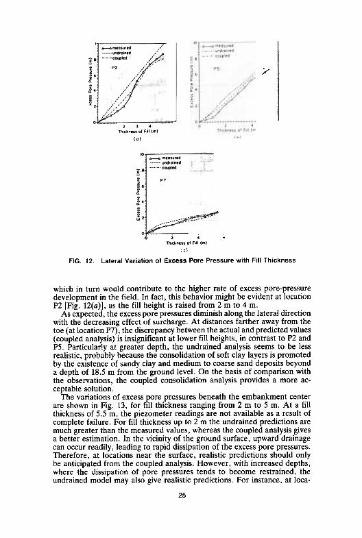
lateral displacements for 13 with increasing fill thickness at a depth of 4.5m, where the displacements increase rapidly as a fill height of 5.0 m isapproached. Cracking of embankment fill and ultimate failure were ob-served in the field at a fill thickness of about 5.5 m. As observed from Fig.14(a), only the coupled consolidation analysis seems to be realistic in pre-dicting the critical height with respect to the variation of displacements,although the computed magnitudes are significantly overestimated, espe-cially at lower fill heights.
The lateral displacement profile with depth for inclinometer 13 at thecritical embankment height (5.5 m) is shown in Fig. 14(b). As expected,the maximum displacements are measured within the upper, very soft claylayer at a depth of 5 m below ground level. As the deeper (stiffer) depositsare encountered the lateral displacements are severely curtailed. As indi-cated before, at depths in excess of 12 m below the ground level, a state ofKo conditions is approached toward the sandy soil deposits. Consequently,while realistic predictions from Cam-clay models can be obtained for theupper, soft clay layer, they deviate from the field behavior at greater depths.
As evident from Fig. 14, the consolidation analysis based on the modifiedCam-clay theory generally overestimates lateral displacements. The reasonfor this discrepancy may be attributed to several factors, including the ac-curacy of soil parameters, the implications of the associated flow rule (nor-mality condition), and the simulation of plane-strain conditions. In addition,the stiff surficial crusts could have restricted the horizontal deformationbeneath the embankment to some extent, which could not be accuratelymodeled in the analysis. It is found that lateral displacements are alsosensitive to nominal changes of A (Balachandran 1990). In this finite-elementanalysis (CRISP), the critical-state parameters were obtained from triaxialCKoU stress-strain behavior in accordance with the modified Cam-clay the-ory. The magnitudes of soil parameters determined in laboratory are notonly influenced by the initial stress conditions but also by the subsequentstress paths followed under given loading-unloading conditions. Althoughthe Cam-clay theory proposes the soil parameters (A,k, and M) to be uniquefor a specific yield surface, the laboratory determination of their magnitudescan be influenced by the nature of stress-path testing (Yau 1990).
~
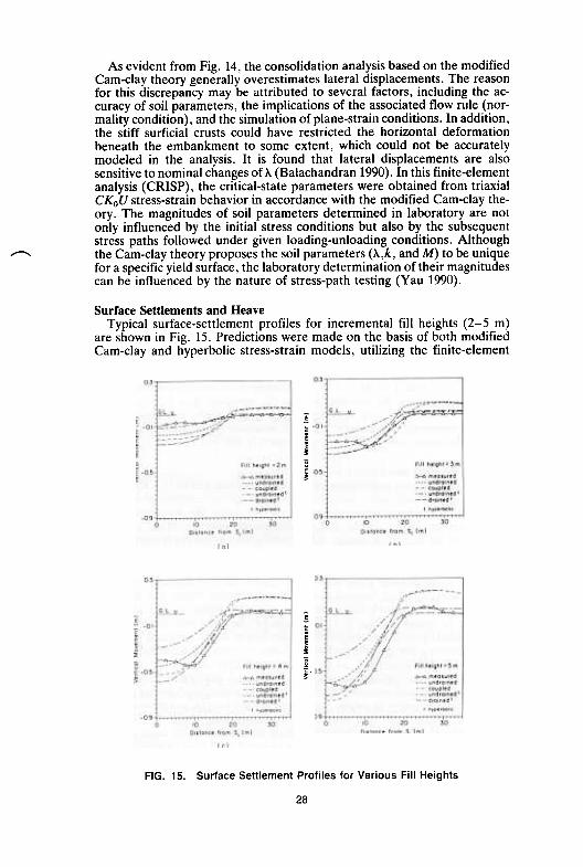
Surface Settlements and HeaveTypical surface-settlement profiles for incremental fill heights (2-5 m)
are shown in Fig. 15. Predictions were made on the basis of both modifiedCam-clay and hyperbolic stress-strain models, utilizing the finite-element
~~~~
~~
~~r£
~~
FIG. 15. Surface Settlement Profiles for Various Fill Heights
28

codes CRISP and ISBILD, respectively. At lower fill heights (up to 2 m),all predictions overestimate vertical settlements; whereas at greater em-bankment heights, the observed values are in excess of predictions exceptin the vicinity of the center line of fill. Contrary to expectations, the meas-urements indicate the occurrence of maximum settlements at a lateral dis-tance of 8-10 m farther away rather than at the center line.
Because the actual field conditions are partly drained, realistic predictionsof surface settlement should be anticipated from a coupled consolidationanalysis. Nevertheless, for initial embankment heights [e.g. Fig. 15(a)], thenonlinear, or hyperbolic, undrained consolidation model gives an acceptablefit to the actual settlement profile for in-situ stresses less than Pmax' This isnot surprising, since at small surcharge loads the total settlements mayprimarily consist of immediate settlements. Although it is not feasible togeneralize as to which constitutive model or consolidation analysis is themost appropriate, it seems that at greater fill heights (3-5 m) the settlementpredictions from the coupled consolidation analysis provides realistic so-lutions. This is expected because at elevated surcharge loads the contributionfrom consolidation settlements (for stresses exceeding the preconsolidationpressure) becomes significant.
The advantage of using the hyperbolic stress-strain model in predictingheave is obvious. In fact, at fill heights close to failure [Fig. 15(d)], theundrained analysis seems to be in better agreement with the measurement.Unfortunately, the modified Cam-clay theory significantly overestimatesheave in the vicinity of the toe. As discussed earlier, this discrepancy maybe partly attributed to the stress-path sensitivity of soil parameters used inCRISP, as well as the deviations from the assumed flow rule (normalitycondition) used in theory. To predict heave accurately, loading-extensiontests representing the actual stress-path behavior in the vicinity of the toemay yield better soil parameters to be used in the analysis.
Subsoil Yielding and Failure SurfacesOnly the coupled undrained-drained consolidation model of CRISP could
predict the overall instrumentation response to an acceptable degree ofaccuracy. Therefore, within the scope of this paper the evaluation of thecritical embankment height and the associated failure surface are basedpurely on the foregoing model. As the embankment height is increased theextent of subsoil yielding becomes greater. The contour plots of normalizedshear stress ratios (shear stress-undrained shear strength) are illustrated inFig. 16. These contour plots were prepared for fill thickness of 4 m and 5.5m (at failure), which indicate potential yield zones where the computedshear stresses approach the undrained shear strengths. It is evident thatyielding is initiated close to the bottom of the very soft clay layer andsubsequently propagates toward the center line as the fill height is increased.By considering the general pattern of these contours, hence identifying theprobable failure zones (T/cu at 1), the potential shear band propagation canbe interpreted in conjunction with the associated displacement vectors.
The inclinometer measurements as well as the predicted lateral displace-ments from the coupled consolidation model indicate the inception of failureat 5.5 m fill thickness. Due to the high degree of compaction of the lateriticembankment fill, it is not surprising that tensile failure of such materialscould take place at extensional strains as small as 0.1-0.25% (Indraratnaet al. 1990). Finite-element analysis indicated maximum tensile strains atthe b3se of the embankment ranging from 0.13% to 0.80% as the fill thick-
29

~
~
c;,
FIG. 17. Maximum Incremental Displacements at Failure
ness was increased from 4.0 m to 5.5 m. The occurrence of a tension modeof failure of the compacted embankment was already mentioned (Fig. 2).
To determine the shear surface through the clay foundation, the maximumincremental displacement vectors were computed along several vertical planesof the finite-element mesh. The predicted shear band interpreted in thismanner is shown in Fig. 17. The boundaries of yielded zones approaching
'On

~:" \
Actuol (SSm) + FEM
I Tension c,ock . Con,entlonolI Bolo(som)e e
I Poulo. (3Bm)
Actuol follu,e .urfoce
Predicted .heo' bond
--!:.m.. ~m
BSm-L-
FIG. 19. Comparison of Finite-Element Predictions with Conventional Limit Equi-
librium Solutions
the critical state are illustrated in Fig. 18, where each contour indicates thecurrent fill height. In the upper, very soft clay layer the inception of failureis evident by the dramatically extended boundary of the yielded zone at 5.5m of fill thickness, in comparison with that of 5.0 m. It is verified that thepredicted shear band (replotted in Fig. 18) is engulfed within the criticalzone corresponding to the failure height of 5.5 m.
Fig. 19 indicates the comparison of the numerically predicted shear bandwith conventional limit-equilibrium solutions by other independent studies.Poulos et al. (1989) recognized the poor tensile properties of the embank-ment fill and also adopted lower-bound vane strengths (uncorrected) forthe soft clay foundation. In contrast, Balasubramaniam et al. (1989) con-sidered the shear-strength mobilization of the embankment fill and appliedcorrected vane strengths for the subsoils. In the present study it can beobserved that the finite-element solution provides a better agreement withthe actual slip surface in comparison with the slip-circle predictions.
CONCLUSIONS
The behavior of a soft marine clay foundation subjected to embankmentloading can be predicted reliably by the coupled consolidation model. How-ever, the accurate prediction of lateral displacements, and heave in partic-'ular, require careful assessment of soil parameters corresponding to theactual stress-path response in the field during embankment loading. Forinstance, a reliable estimation of parameters with respect to heave at thevicinitv of the toe mav reQuire loading-extension conditions to be simulated

~
in triaxial tests, in preference to loading-compression. With regard to themodified Cam-clay model, the associated flow rule in general overestimatespost yield displacements. In this respect, application of the continuous plas-ticity version of the critical-state model (Naylor 1985) or bounding-surfaceformulation (Dafalias and Hermann 1982) may be promising in describinganisotropic yielding. However, considering the relative simplicity of Cam-clay theories, if one were to employ any complex constitutive model infinite-element analysis, the additional computational efforts should be jus-tified not only by a superior conceptual picture, but also by more realisticnumerical predictions. '
Purely undrained analysis irrespective of whether it is based on the mod-ified Cam-clay or the hyperbolic stress-strain model is generally not reliableexcept at central regions of the clay formation, at depths of 7-9 m belowground level. In the vicinity of the ground surface, the dissipation of excesspore pressures is facilitated. At much greater depths toward the sandy soils,not only are the displacements reduced, but also a state of Ko conditions isapproached. Purely undrained deformation analysis is unrealistic for suchsituations.
The finite-element analysis is capable of predicting the correct mode offailure by considering the incremental displacement vectors and mobilizedshear stress contours. The occurrence of excessive tensile strains at the baseof the embankment has undoubtedly encouraged cracking of the heavilycompacted fill irrespective of its shear strength. In fact, the cracking of thetopmost weathered clay crust could also be interpreted in a similar mannerif the tensile properties of the crust were available. The predicted shear-band propagation by the finite-element analysis compares well with theobserved slip surface. On the other hand, limit-equilibrium methods ofanalysis are capable of predicting the actual failure surface only if the shearstrength of the embankment fill is properly taken into consideration.
It can be envisaged that higher embankments can be raised on soft claydeposits if the tensile mode of failure of the compacted fills can be sup-pressed. Therefore, the ,utilization of a backfill with sufficient shear resist-ance supported by internal reinforcements such as geogrids should be en-couraged in the construction of high embankments. Furthermore, the presenceof a rigid layer (crust) beneath the embankment can resist lateral displace-ments, promoting a greater height offill prior to failure. In effect, this wouldencourage the use of additives in surface stabilization.
ACKNOWLEDGMENTS
The writers gratefully appreciate the assistance provided by Miss E. L.G. Dilema, Mr. N. S. Nilaweera, and Mr. Ranjith Premalal during thepreparation of this manuscript. The second writer particularly wishes tothank the Malaysian Highway Authority for inviting him to be one of thefour international predictors for the Symposium on Trial Embankments onMalaysian Marine Clays, held in November 1989. The writers also extendtheir sincere thanks to Mr. Robert Hudson and Dr. E. W. Brand for theirtechnical assistance in numerous ways.
ApPENDIX. REFERENCES
Balachandran, S. (1990). "Simulation of a test embankment failure (Muar floodplain, Malaysia) using finite element techniques coupled with critical state soilmechanics," thesis presented to the Asian Institute of Technology, at Bangkok,
32
Thailand, in partial fulfillment of the requirement for the degree of Master ofScience.
Balasubramaniam, A. S., Phien-wej, N., Indraratna, B., and Bergado, D. T. (1989)."Predicted behavior of a test embankment on a Malaysian marine clay." Int. Symp.on Trial Embankments on Malaysian Marine Clays, Kuala Lumpur, Malaysia, Vol.2, 1-1-1-8.
Bjerrum, L. (1973). "Problems of soil mechanics and construction on soft clays.State-of-the-art report to Session IV." 8th Int. Conf. on Soil Mech. and Found.Engrg., Moscow, U.S.S.R.
Brand, E. W., and Premchitt, J. (1989). "Moderator's report for the predictedperformance of the Muar test embankment," Proc., Int. Symp. on Trial Em-bankment on Malaysian Marine Clays, Kuala Lumpur, Malaysia, Vol. 2, 1/32-1/49.
Britto, A. M., and Gunn, M. J. (1984). CRISP user's and programmer's guide.Cambridge University, Cambridge, England.
Britto, A. M., and Gunn, M. J. (1987). Critical state soil mechanics via finite elements.Ellis Horwood, Chichester, England.
Dafalias, Y. F., and Herrman, L. R. (1982). "Bounding surface formulation of soilplasticity." Soil mechanics-transient and cyclic loads G. N. Pande and O. C.Zienkiewicz, eds" John Wiley and Sons, New York, N.Y., 253-282.
Indraratna, B., Dilema, E. L. G., and Nutalaya, P. (1990). Suitabilfty of lateriticresidual soil for core compaction and design of appropriate granular filters. DamEngrg., 1(3),201-220.
Kulhawy, F. H., Duncan, J. M., and Seed, H. B. (1969). "Finite element analysisof stresses and movements in embankments during construction." Contract ReportNo. S-69-8, USAEWES, Vicksburgh, Miss,
Naylor, D. J. (1975). "A continuous plasticity version of the critical state model."Int. J. Num. Meth. in Engrg., 21(7), 1187-1204.
Ozawa, Y., and Duncan, J. M. (1973). ISBILD: A computer program for staticanalysis of static stresses and movement in embankment. University of California,Berkeley, Calif.
Poulos, H. G., Lee, C. Y., and Small, J. C. (1989). "Prediction of embankmentperformance on Malaysian marine clays." Int. Symp. on Trial Embankments onMalaysian Marine Clays, Kuala Lumpur, Malaysia, Vol. 2, 1-22-1-31.
Proc., Int. Symp. on Trial Embankments on Malaysian Marine Clays, (1989). Ma-laysian Highway Authority, Kuala Lumpur, Malaysia.
Roscoe, K. H., and Burland, J. B. (1968). "On the generalized stress strain behaviorof wet clay." Engineering plasticity. Cambridge University Press, Cambridge,England.
Roscoe, R. H., and Poorooshasb, H. B. (1963). "A theoretical and experimentalstudy of strains in triaxial tests on normally consolidated clays." Geotechnique,London, England, Vol. 13, 12-38.
Yau, K. F. (1990). "Stress paths below embankments and excavations in Bangkoksubsoils, thesis presented to the Asian Institute of Technology, at Bangkok, Thai-land, in partial fulfillment of the requirements for the degree of Master of Science.
33