Embed Size (px)
Citation preview

Shijia ZhaoDepartment of Mechanical
and Materials Engineering,
University of Nebraska-Lincoln,
Lincoln, NE, 68588-0656
Linxia Gu1
Department of Mechanical
and Materials Engineering,
University of Nebraska-Lincoln,
Lincoln, NE 68588-0656;
Nebraska Center for Materials
and Nanoscience,
Lincoln, NE, 68588-0656
e-mail: [email protected]
Stacey R. FroemmingHybrid Catheterization and Electrophysiology
Laboratory,
Children’s Hospital and Medical Center,
Omaha, NE, 68114-4133
Performance of Self-ExpandingNitinol Stent in a Curved Artery:Impact of Stent Length andDeployment OrientationThe primary aim of this work was to investigate the performance of self-expanding Nitinolstents in a curved artery through finite element analysis. The interaction between a PRO-TEGETM GPSTM self-expanding Nitinol stent and a stenosed artery, as well as a sheath,was characterized in terms of acute lumen gain, stent underexpansion, incomplete stentapposition, and tissue prolapse. The clinical implications of these parameters were dis-cussed. The impact of stent deployment orientation and the stent length on the arterial wallstress distribution were evaluated. It was found that the maximum principal stressincreased by 17.46%, when the deployment orientation of stent was varied at a 5 deg angle.A longer stent led to an increased contact pressure between stent and underlying tissue,which might alleviate the stent migration. However, it also caused a severe hinge effectand arterial stress concentration correspondingly, which might aggravate neointimalhyperplasia. The fundamental understanding of the behavior of a self-expanding stent andits clinical implications will facilitate a better device design. [DOI: 10.1115/1.4007095]
Keywords: self-expanding stent, Nitinol, curved artery, stent-artery interaction, stentunderexpansion, acute lumen gain, incomplete stent apposition, tissue prolapse
1 Introduction
Self-expanding Nitinol stents are increasingly popular in treat-ing arterial occlusions, especially peripheral arterial disease. How-ever, long-term patency of a stented vessel remains a challengedue to tissue ingrowth through the mesh structure of metal stents.The mechanism of arterial reocculusion is not yet fully under-stood. It is speculated that many factors, such as excessive stretchof the arterial wall, stent underexpansion, incomplete stent apposi-tion (ISA), dimension and tortuosity of the artery contribute to theoccurrence of reocclusion [1–3]. Evaluation of the mechanics ofstent deployment and its interactions with diseased lesion will pro-vide a fundamental understanding of stent dynamics and mechani-cal changes in the vessel wall.
Finite element method (FEM) has proven to be a very efficientand effective tool for the study of balloon-expandable stents, suchas stent deployment and stent–artery interactions [4–9]. The inter-action between self-expanding stents and arteries has undergonefar less investigation using FEM. Moreover, most computationalstudies available in the literature focus on idealized straight ves-sels. Kleinstreuer et al. [10] simulated two Nitinol stent grafts totreat the abdominal aortic aneurysm in a straight vessel. Miglia-vacca et al. [11] compared stainless steel and Nitinol stentsdeployed into a straight coronary artery with a simplified cylindri-cal plaque. Several studies deployed a Nitinol stent into an ana-tomically accurate artery; however, plaque was not taken intoaccount [12,13]. Wu et al. [14] simulated the delivery and releaseof Nitinol stent in a curved carotid artery; however, an idealizedcylindrical plaque, corresponding to a 33% stenosis, was consid-ered, which is usually not clinically significant for stent implanta-tion. The effects of the stent deployment technique are alsolacking in the documented finite element models. In addition,
there is growing clinical evidence that self-expanding stentsextend the duration of patency after treating the stenosed vessel,particularly when compared with balloon-mounted stents [15].Therefore, better modeling of the deployment of the Nitinol stentand its interaction with curved stenosed artery will improve pre-dictions of the stent performance and the design of a new genera-tion of stents. The aim of this study is to systematically determinethe behavior of a PROTEGETM GPSTM self-expanding stent (ev3Inc., Plymouth, MN, USA) in a curved artery. The detailed inter-action between stent, plaque and artery, the influence of stentdeployment orientation and stent length on the level of the injuryare presented and discussed.
2 Material and Methods
2.1 Geometry. A curved artery with 50% stenosis, based onthe corresponding clinical study [16], was considered in this work(Fig. 1). The reference lumen dimensions are 9 mm in diameter,1 mm in thickness, and 0.05 mm�1 in curvature [17]. The arc cen-tral angle between two ends of artery is 90 deg, which produces anarc length of 31.4 mm at the central line of artery. An asymmetricplaque which produces eccentric lumen [18] was attached ontothe inner surface of artery, and the arc length at inner surface of
Fig. 1 Sectional view of the sheath-restrained Nitinol stent in acurved artery
1Corresponding author.Contributed by the Bioengineering Division of ASME for publication in the
JOURNAL OF BIOMECHANICAL ENGINEERING. Manuscript received January 12, 2012; finalmanuscript received June 3, 2012; accepted manuscript posted July 6, 2012;published online July 17, 2012. Assoc. Editor: Tim David.
Journal of Biomechanical Engineering JULY 2012, Vol. 134 / 071007-1Copyright VC 2012 by ASME
Downloaded From: http://biomechanical.asmedigitalcollection.asme.org/ on 04/24/2016 Terms of Use: http://www.asme.org/about-asme/terms-of-use
plaque is around 16 mm. The PROTEGETM GPSTM self-expanding Nitinol stent was constrained by a sheath and deliveredto the lesion site (Fig. 2). There are 16 units along the circumfer-ential direction and nine units along the axial direction in the con-figuration of the stent, which led to a nominal diameter of 10 mm,length of 20 mm, and strut thickness of 0.22 mm.
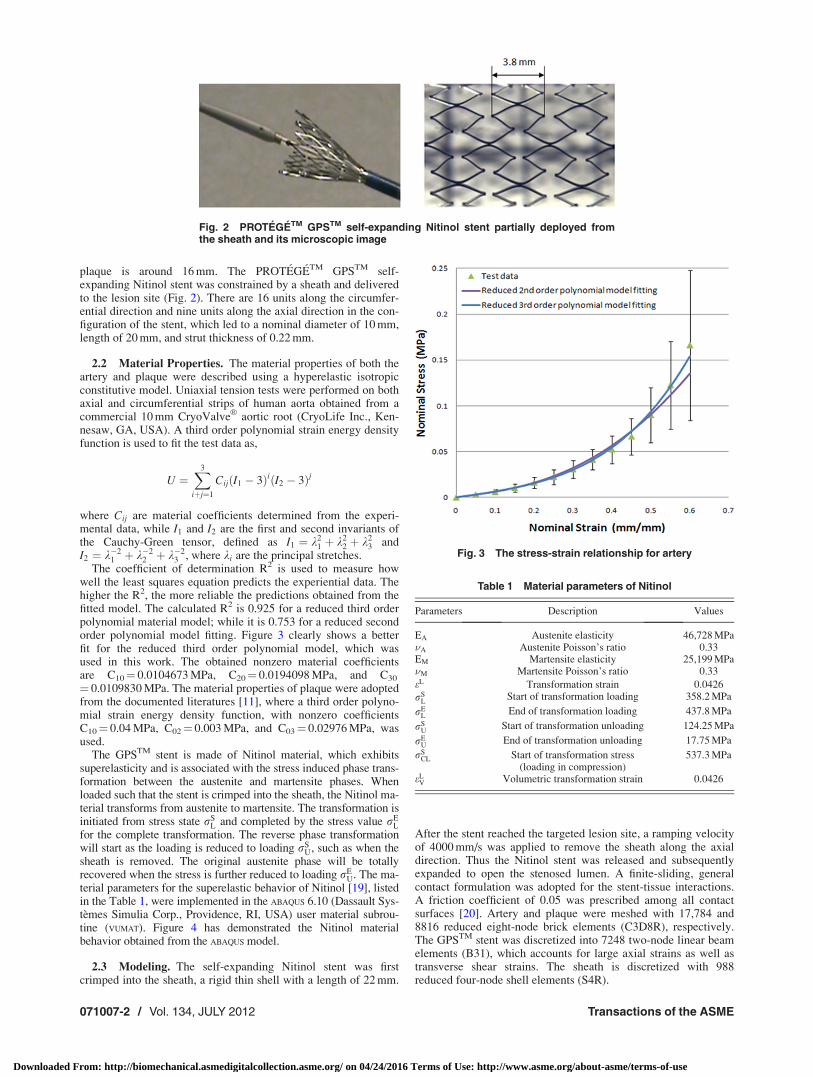
2.2 Material Properties. The material properties of both theartery and plaque were described using a hyperelastic isotropicconstitutive model. Uniaxial tension tests were performed on bothaxial and circumferential strips of human aorta obtained from acommercial 10 mm CryoValve
VR
aortic root (CryoLife Inc., Ken-nesaw, GA, USA). A third order polynomial strain energy densityfunction is used to fit the test data as,
U ¼X3
iþj¼1
CijðI1 � 3ÞiðI2 � 3Þj
where Cij are material coefficients determined from the experi-mental data, while I1 and I2 are the first and second invariants ofthe Cauchy-Green tensor, defined as I1 ¼ k2
1 þ k22 þ k2
3 andI2 ¼ k�2
1 þ k�22 þ k�2
3 , where ki are the principal stretches.The coefficient of determination R2 is used to measure how
well the least squares equation predicts the experiential data. Thehigher the R2, the more reliable the predictions obtained from thefitted model. The calculated R2 is 0.925 for a reduced third orderpolynomial material model; while it is 0.753 for a reduced secondorder polynomial model fitting. Figure 3 clearly shows a betterfit for the reduced third order polynomial model, which wasused in this work. The obtained nonzero material coefficientsare C10¼ 0.0104673 MPa, C20¼ 0.0194098 MPa, and C30
¼ 0.0109830 MPa. The material properties of plaque were adoptedfrom the documented literatures [11], where a third order polyno-mial strain energy density function, with nonzero coefficientsC10¼ 0.04 MPa, C02¼ 0.003 MPa, and C03¼ 0.02976 MPa, wasused.
The GPSTM stent is made of Nitinol material, which exhibitssuperelasticity and is associated with the stress induced phase trans-formation between the austenite and martensite phases. Whenloaded such that the stent is crimped into the sheath, the Nitinol ma-terial transforms from austenite to martensite. The transformation isinitiated from stress state rS
L and completed by the stress value rEL
for the complete transformation. The reverse phase transformationwill start as the loading is reduced to loading rS
U, such as when thesheath is removed. The original austenite phase will be totallyrecovered when the stress is further reduced to loading rE
U. The ma-terial parameters for the superelastic behavior of Nitinol [19], listedin the Table 1, were implemented in the ABAQUS 6.10 (Dassault Sys-temes Simulia Corp., Providence, RI, USA) user material subrou-tine (VUMAT). Figure 4 has demonstrated the Nitinol materialbehavior obtained from the ABAQUS model.
2.3 Modeling. The self-expanding Nitinol stent was firstcrimped into the sheath, a rigid thin shell with a length of 22 mm.
After the stent reached the targeted lesion site, a ramping velocityof 4000 mm/s was applied to remove the sheath along the axialdirection. Thus the Nitinol stent was released and subsequentlyexpanded to open the stenosed lumen. A finite-sliding, generalcontact formulation was adopted for the stent-tissue interactions.A friction coefficient of 0.05 was prescribed among all contactsurfaces [20]. Artery and plaque were meshed with 17,784 and8816 reduced eight-node brick elements (C3D8R), respectively.The GPSTM stent was discretized into 7248 two-node linear beamelements (B31), which accounts for large axial strains as well astransverse shear strains. The sheath is discretized with 988reduced four-node shell elements (S4R).
Fig. 2 PROTEGETM GPSTM self-expanding Nitinol stent partially deployed fromthe sheath and its microscopic image
Fig. 3 The stress-strain relationship for artery
Table 1 Material parameters of Nitinol
Parameters Description Values
EA Austenite elasticity 46,728 MPa�A Austenite Poisson’s ratio 0.33EM Martensite elasticity 25,199 MPa�M Martensite Poisson’s ratio 0.33
eL Transformation strain 0.0426
rSL
Start of transformation loading 358.2 MPa
rEL
End of transformation loading 437.8 MPa
rSU
Start of transformation unloading 124.25 MPa
rEU
End of transformation unloading 17.75 MPa
rSCL Start of transformation stress
(loading in compression)537.3 MPa
eLV Volumetric transformation strain 0.0426
071007-2 / Vol. 134, JULY 2012 Transactions of the ASME
Downloaded From: http://biomechanical.asmedigitalcollection.asme.org/ on 04/24/2016 Terms of Use: http://www.asme.org/about-asme/terms-of-use

3 Results
The GPSTM Nitinol stent restored patency in a curved vesselwith 50% stenosis, as shown in Fig. 5. After stenting, the stentlength is 21.77 mm, compared with the original length of 20 mm.The diameter of the stent is 7.72 mm at the center of the plaque,10.01 mm at the proximal end of the stent, and 10.04 mm atthe distal end of the stent, respectively. This indicates a possiblestent underexpansion, evaluated as the ratio of minimum stentarea to the mean proximal and distal reference lumen area [21].
Underexpansion occurs if this ratio is less than 80% [21]. In thiswork, the minimum lumen cross-sectional area enclosed by thestent is calculated as 50.22 mm2 while the proximal and distal ref-erence lumen area are 91.78mm2 and 87.38 mm2, respectively.The corresponding ratio is 56.06%, which indicates the presenceof underexpansion. Underexpansion usually leads to noncontactregions between the stent and artery wall, also referred to asincomplete stent apposition (ISA) [22]. The stent strut is not fullyflush against the wall, and hence a lack of contact between thestrut and the underlying arterial wall. An ISA area of 160.55 mm2
is obtained in our model.Acute lumen gain, quantified as the increase in lumen diameter,
is a positive indicator of stent performance. The minimum lumendiameter increased from the initial 4.5 mm to 7.61 mm, which cor-responded to a 15.44% residual stenosis after stenting, as illus-trated in Fig. 6 and Table 2. The variable D refers to the innerdiameter of the artery, and tmax, tmin refer to the limit thickness ofthe plaque at one cross-section. An acute lumen gain is calculatedas 3.11 mm due to plaque compressions and arterial wall stretch-ing. It is clear that the stented artery is stretched by 23.44%, andreaches to an inner diameter of 11.11 mm at the site of narrowestocclusion. The plaque, however, was compressed by 0.63 mm(Dtmax) and 0.37 mm (Dtmin), respectively, which indicates a21.00% compression in the thick side of the plaque, and 24.67%compression in the thin side of the plaque. Similar compressionsare also observed at both plaque ends with around 22% arterialstretch. In our case, arterial wall stretch contributes to approxi-mately 68% of the lumen gain at the site of narrowest occlusion;in addition to plaque compression and redistribution.
Acute lumen gains are compromised by tissue prolapse, esti-mated as the maximal protrusion of the arterial tissue betweenstent struts. The tissue prolapse, defined as the relative radial dis-tance between the protruded tissue and its surrounding strut, is0.44 mm at maximum in the central cross-sections, which is largerthan the stent strut thickness of 0.22 mm, indicating the lumenloss due to the draping of the tissue within the units of the stent.This may affect the hemodynamics and induce late stent thrombo-sis and in-stent restenosis [23].
Deployment of stent induced stress concentrations on the arte-rial wall, which contribute to the occurrence of in-stent restenosis.Figure 7(a) demonstrates that stent implantation straightened thecurved vessel wall and that the stent ends poked into the artery,this phenomenon is referred to as the hinge effect. The effect ofcatheter tilting is estimated by inclining the crimped stent 5 deg
Fig. 4 The hysteresis behavior of Nitinol obtained from ABAQUS
Fig. 5 The deformation of the artery, plaque, and stent in thecurved stenosed artery
Fig. 6 The cross section of stenosed artery at site of narrowest occlusion. (a) beforestenting; (b) after stenting. Where D denotes the inner diameter of the artery, tmin and tmax
are the plaque thickness at its thin and thick side, respectively.
Journal of Biomechanical Engineering JULY 2012, Vol. 134 / 071007-3
Downloaded From: http://biomechanical.asmedigitalcollection.asme.org/ on 04/24/2016 Terms of Use: http://www.asme.org/about-asme/terms-of-use

counterclockwise against the initial center positioning (Fig. 7(b)).The maximum principal stress in the arterial wall increased from0.063 MPa to 0.074 MPa after stent tilting. Meanwhile, the stent-induced distal hinge effect becomes more prominent. The maxi-mum principal nominal strain at the distal end was elevated from33.99% to 38.69%, which was a 13.83% increase due to the 5 degorientation variation. It is natural to observe that the hinge effectwas alleviated at the proximal end of the stent, where the maxi-mum principal nominal strain at the hinge points decreased from36.22% to 31.28%.
The influence of stent length is investigated by adding two orfour more units onto the original stent, which has nine units aloneaxial direction. The stent with nine units along the axial directionwas referred to as “Stent U9” and the ones with 11 or 13 units as“Stent U11” or “Stent U13,” respectively. The lumen gain afterstenting of “Stent U11” and “Stent U13” were 3.40 mm and3.44 mm, respectively, comparing with 3.11 mm for the original“Stent U9.” The maximum contact pressure between stent andunderlying tissue for “Stent U9,” “Stent U11,” and “Stent U13”were 0.27 MPa, 0.31 MPa, and 0.45 MPa, respectively. Theincreased stent length also led to severe arterial stress concentra-tions, as shown in Fig. 8. The arterial volume where principalstress exceeds 0.06 MPa, the average blood pressure induced arte-rial stress level, were 0.01%, 2.54%, and 11.95% after deploymentof “Stent U9,” “Stent U11,” and “Stent U13,” respectively.
4 Discussion
In this study, the deployment of a self-expanding Nitinol stentin a curved artery is simulated to get a better fundamental under-standing of the interaction between the stent and the stenosed ar-tery, as well as its clinical implications. Both artery and plaqueunderwent considerable geometry change immediately after thedeployment of Nitinol stent. This agrees with the documentedclinical observations, which showed that arterial wall stretchingand plaque compression are the two main contributors to lumen
gain after stenting [24]. It is also clear that the thin side of plaquewas compressed more than the thick side, which caused higher ar-terial stress contacting the thin side of plaque (Fig. 6 and Table 2).This may be explained by the lower resistance at the thin side ofthe plaque. A stenting study in rabbits showed a positive correla-tion between the extent of plaque or medial compression and theobserved neointimal hyperplasia [25]. This implied that the variedmedial compressions might lead to nonuniform thickening of theintima of the stented artery. Results show that Nitinol stents ex-hibit underexpansion immediately after its deployment. This ispartially attributed to the lower stiffness of Nitinol as a material(47 GPa), compared with the conventional stainless steel materialwith a stiffness of 190 GPa. It is speculated that the underexpan-sion of bare metal stents is associated with thrombosis and theoccurrence of restenosis [21,26–28]. Post balloon angioplasty af-ter stent deployment is suggested by some researchers to reducethe underexpansion [29]. Other groups, however, have suggestedthat Nitinol stents will continue expanding to listed nominal diam-eter up to nine months after the deployment; thus acute underex-pansion may be corrected by the stent itself due to its shapememory properties [30–32]. Late expansion of Nitinol stents maycompensate the lumen loss caused by neointimal hyperplasia;however, it is at the expense of arterial overstretching [31,32].
This work has shown that underexpansion may lead toincreased hinge effect at both ends of the stent, especially whenthe catheter is slightly tilted. The influence of tilted catheter canbe extended to various arterial curvatures, but it is pronounced inarteries with larger curvatures. Considering the reality of catheter
Table 2 Stent-induced variations in the geometry of stenosed artery
tmax (mm) tmin (mm) D (mm)
Plaque center(narrowest occlusion)
Before stenting 3.00 1.50 9.00After stenting 2.37 1.13 11.11
Plaque ends Before stenting 1.57 0.94 9.32After stenting (Proximal) 1.40 0.63 11.40
After stenting (Distal) 1.45 0.66 11.33
Fig. 7 Arterial stress distributions after stent deployment. (a)catheter along the center of the lumen; (b) tilted catheter with5 deg angle counterclockwise.
Fig. 8 The influence of stent length on arterial wall stress. (a)“Stent U9,” (b) “Stent U11,” and (c) “Stent U13”.
071007-4 / Vol. 134, JULY 2012 Transactions of the ASME
Downloaded From: http://biomechanical.asmedigitalcollection.asme.org/ on 04/24/2016 Terms of Use: http://www.asme.org/about-asme/terms-of-use

position in a curved artery, the initial stent deployment orientationis rotated for 5 deg angle. The maximum principal nominal strainat the distal end increased by 13.83%, which indicates a moresevere hinge effect. The hinge effect, due to the nonuniformasymmetric plaque, stent oversizing, and underexpansion, willcause higher local stresses and stress gradients on the artery. Thismay trigger neointimal proliferation at those locations, and con-tribute to the occurrence of restenosis [33]. Meanwhile, the peakstress gradient may lead to edge dissection, which requires furtherintervention [34,35]. Considering the smaller contact load at thestent ends, soft strut links at the ends of stents are suggested to al-leviate these hinge effects [36].
The tortuosity of the stenosed artery was modified by theimplanted stent. This is clearly demonstrated by the stentedcurved vessel. The nonuniform plaque profile caused noncontactregions between the stent and arterial wall. This implies that drug-eluting stents may sacrifice the drug effect on the artery, andblood stagnation may form in theseareas which may initiatethrombosis. It is speculated that more units with shorter struts willreduce the ISA area and increase the compliance of the stentsused in tortuous artery [14].
The effect of stent length was evaluated in terms of contactpressure between stent and underlying tissue and the potentialinjury to the arterial wall. It is clear that a longer self-expandingstent enhances the contact pressure between stent and underlyingtissue, which may reduce the stent migration [37]. The instantlumen gain was also improved with a longer stent that protrudeswide into the normal portions of the artery. However, the longerstent induced more severe hinge effect and much larger stress con-centrations at the ends of the stents, which may increase the possi-bility of neointimal hyperplasia.
In this study, the baseline stenosis of 50% was adopted fromthe clinical studies of PROTEGETM GPSTM carotid stent [16].For the stenting treatment of severe stenosis, i.e., 70% or greater,a balloon predilation was generally needed [30], which was notconsidered in this work. The material properties of artery andplaque are defined as homogeneous, isotropic, and hyperelastic,though they have been shown to be nonhomegeneous, aniso-tropic, and viscoelastic [38,39]. Hyperelastic constitutive equa-tions were extensively used to describe the nonlinear stress-strainrelationship for the elastic state of arterial tissue; however, theinelastic phenomena such as plastic or fracture-related deforma-tion could not be addressed by the hyperelastic material modelitself. Effects of blood flow and more realistic material modelswere not considered in this work. The superelasticity of Nitinolstents is considered to accommodate large strains in this work;however, its shape memory properties related to temperaturedriven deformation was neglected, which will become essentialto model the late expansion. The geometry of the artery andplaque were idealized for this comparative study. An MRIreconstructed model may change the stress concentration on thearterial wall. With the advancement of finite element models,clinical treatment planning through finite element method couldhelp to predict the clinical outcomes. In spite of these limitations,this study demonstrated the performance of Nitinol stents in acurved artery in terms of underexpansion, ISA, hinge effect, andstress concentration. The results obtained herein provideguidance for optimizing stent designs and potential clinicalperformance.
Acknowledgment
The authors are grateful for funding from the National ScienceFoundation under Grant Nos. 0926880 and 0811250.
References[1] Gu, L. X., Zhao, S. J., Muttyam, A. K., and Hammel, J. M., 2010, “The Relation
Between the Arterial Stress and Restenosis Rate After Coronary Stenting,”J. Med. Devices, 4(3), p. 031005.
[2] Kim, W., Jeong, M. H., Lee, S. R., Lim, S. Y., Hong, Y. J., Ahn, Y. K., andKang, J. C., 2007, “An Accordion Phenomenon Developed After Stenting in aPatient With Acute Myocardial Infarction,” Int. J. Cardiol., 114(2), pp.E60–E62.
[3] Zhou, R. H., Lee, T. S., Tsou, T. C., Rannou, F., Li, Y. S., Chien, S., and Shy, J.Y., 2003, “Stent Implantation Activates AKT in the Vessel Wall: Role of Me-chanical Stretch in Vascular Smooth Muscle Cells,” Arterioscler., Thromb.,Vasc. Biol., 23(11), pp. 2015–2020.
[4] Bedoya, J., Meyer, C. A., Timmins, L. H., Moreno, M. R., and Moore, J. E.,2006, “Effects of Stent Design Parameters on Normal Artery Wall Mechanics,”J. Biomech. Eng., 128(5), pp. 757–765.
[5] Holzapfel, G. A., Stadler, M., and Gasser, T. C., 2005, “Changes in the Me-chanical Environment of Stenotic Arteries During Interaction With Stents:Computational Assessment of Parametric Stent Designs,” J. Biomech. Eng.,127(1), pp. 166–180.
[6] Lally, C., Dolan, F., and Prendergast, P. J., 2005, “Cardiovascular Stent Designand Vessel Stresses: A Finite Element Analysis,” J. Biomech., 38(8), pp.1574–1581.
[7] Zahedmanesh, H., Kelly, D. J., and Lally, C., 2010, “Simulation of a Balloon Ex-pandable Stent in a Realistic Coronary Artery-Determination of the OptimumModelling Strategy,” J. Biomech., 43(11), pp. 2126–2132.
[8] Pericevic, I., Lally, C., Toner, D., and Kelly, D. J., 2009, “The Influence of Pla-que Composition on Underlying Arterial Wall Stress During Stent Expansion:The Case for Lesion-Specific Stents,” Med. Eng. Phys., 31(4), pp. 428–433.
[9] De Beule, M., Mortier, P., Carlier, S. G., Verhegghe, B., Van Impe, R., andVerdonck, P., 2008, “Realistic Finite Element-Based Stent Design: The Impactof Balloon Folding,” J. Biomech., 41(2), pp. 383–389.
[10] Kleinstreuer, C., Li, Z., Basciano, C. A., Seelecke, S., and Farber, M. A., 2008,“Computational Mechanics of Nitinol Stent Grafts,” J. Biomech., 41(11), pp.2370–2378.
[11] Migliavacca, F., Petrini, L., Massarotti, P., Schievano, S., Auricchio, F., andDubini, G., 2004, “Stainless and Shape Memory Alloy Coronary Stents: AComputational Study on the Interaction With the Vascular Wall,” Biomech.Model. Mechanobiol., 2(4), pp. 205–217.
[12] Conti, M., Auricchio, F., De Beule, M., and Verhegghe, B., 2009, “NumericalSimulation of Nitinol Peripheral Stents: From Laser-Cutting to Deployment ina Patient Specific Anatomy,” Proceedings of the 8th European Symposium onMartensitic Transformations, Prague, Czech Republic.
[13] Rebelo, N., Fu, R., and Lawrenchuk, M., 2009, “Study of a Nitinol StentDeployed into Anatomically Accurate Artery Geometry and Subjected to Real-istic Service Loading,” J. Mater. Eng. Perform., 18(5–6), pp. 655–663.
[14] Wu, W., Qi, M., Liu, X. P., Yang, D. Z., and Wang, W. Q., 2007, “Delivery andRelease of Nitinol Stent in Carotid Artery and their Interactions: A Finite Ele-ment Analysis,” J. Biomech., 40(13), pp. 3034–3040.
[15] Levy, E. I., Sauvageau, E., Hanel, R. A., Parikh, R., and Hopkins, L. N., 2006,“Self-Expanding Versus Balloon-Mounted Stents for Vessel Recanalization fol-lowing Embolic Occlusion in the Canine Model: Technical Feasibility Study,”Am. J. Neuroradiol., 27(10), pp. 2069–2072.
[16] FDA(P060001), 2007, “Summary of Safety and Effectiveness Data (SSED),Protege
VR
GPSTM Carotid Stent System,” ev3 Inc.[17] Prosi, M., Perktold, K., Ding, Z., and Friedman, M. H., 2004, “Influence of Cur-
vature Dynamics on Pulsatile Coronary Artery Flow in a Realistic BifurcationModel,” J. Biomech., 37(11), pp. 1767–1775.
[18] De Franco, A. C., and Nissen, S. E., 2001, “Coronary Intravascular Ultrasound:Implications for Understanding the Development and Potential Regression ofAtherosclerosis,” Am. J. Cardiol., 88(10A), pp. 7M–20M.
[19] Rebelo, N., Walker, N., and Foadian, H., 2001, “Simulation of ImplantableNitinol Stents,” Proceedings of the 2001 Abaqus Users Conference, Providence,Rhode Island, USA.
[20] Dunn, A. C., Zaveri, T. D., Keselowsky, B. G., and Sawyer, W. G., 2007,“Macroscopic Friction Coefficient Measurements on Living Endothelial Cells,”Tribol. Lett., 27(2), pp. 233–238.
[21] Uren, N. G., Schwarzacher, S. P., Metz, J. A., Lee, D. P., Honda, Y., Yeung, A.C., Fitzgerald, P. J., and Yock, P. G., 2002, “Predictors and Outcomes of StentThrombosis: An Intravascular Ultrasound Registry,” Eur. Heart J., 23(2), pp.124–132.
[22] Cheneau, E., Satler, L. F., Escolar, E., Suddath, W. O., Kent, K. M., Weissman,N. J., Waksman, R., and Pichard, A. D., 2005, “Underexpansion of Sirolimus-Eluting Stents: Incidence and Relationship to Delivery Pressure,” Cathet Cardi-ovasc. Intervent., 65(2), pp. 222–226.
[23] Farb, A., Burke, A. P., Kolodgie, F. D., and Virmani, R., 2003, “PathologicalMechanisms of Fatal Late Coronary Stent Thrombosis in Humans,” Circulation,108(14), pp. 1701–1706.
[24] Albrecht, D., Kaspers, S., Fussl, R., Hopp, H. W., and Sechtem, U., 1996,“Coronary Plaque Morphology Affects Stent Deployment: Assessment by Intra-coronary Ultrasound,” Cathet. Cardiovasc. Diagn., 38(3), pp. 229–235.
[25] Carter, A. J., Farb, A., Gould, K. E., Taylor, A. J., and Virmani, R., 1999, “TheDegree of Neointimal Formation After Stent Placement in Atherosclerotic Rab-bit Iliac Arteries is Dependent on the Underlying Plaque,” Cardiovasc. Pathol.,8(2), pp. 73–80.
[26] Cheneau, E., Leborgne, L., Mintz, G. S., Kotani, J., Pichard, A. D., Satler, L. F.,Canos, D., Castagna, M., Weissman, N. J., and Waksman, R., 2003, “Predictorsof Subacute Stent Thrombosis: Results of a Systematic Intravascular UltrasoundStudy,” Circulation, 108(1), pp. 43–47.
[27] Duda, S. H., Wiskirchen, J., Tepe, G., Bitzer, M., Kaulich, T. W., Stoeckel, D.,and Claussen, C. D., 2000, “Physical Properties of endovascular Stents: An Ex-perimental Comparison,” J. Vasc. Intervent. Radiol., 11(5), pp. 645–654.
Journal of Biomechanical Engineering JULY 2012, Vol. 134 / 071007-5
Downloaded From: http://biomechanical.asmedigitalcollection.asme.org/ on 04/24/2016 Terms of Use: http://www.asme.org/about-asme/terms-of-use

[28] Fujii, K., Carlier, S. G., Mintz, G. S., Yang, Y. M., Moussa, I., Weisz, G., Dan-gas, G., Mehran, R., Lansky, A. J., Kreps, E. M., Collins, M., Stone, G. W.,Moses, J. W., and Leon, M. B., 2005, “Stent Underexpansion and Residual Ref-erence Segment Stenosis are Related to Stent Thrombosis After Sirolimus-Eluting Stent Implantation: An Intravascular Ultrasound Study,” J. Am. Coll.Cardiol., 45(7), pp. 995–998.
[29] Romagnoli, E., Sangiorgi, G. M., Cosgrave, J., Guillet, E., and Colombo, A.,2008, “Drug-Eluting Stenting: The Case for Post-Dilation,” J. Am. Coll.Caridol.: Cardiovasc. Intervent., 1(1), pp. 22–31.
[30] Lownie, S. P., Pelz, D. M., Lee, D. H., Men, S., Gulka, I., and Kalapos, P.,2005, “Efficacy of Treatment of Severe Carotid Bifurcation Stenosis by UsingSelf-Expanding Stents Without Deliberate Use of Angioplasty Balloons,” Am.J. Neuroradiol., 26(5), pp. 1241–1248.
[31] Sanmartin, M., Goicolea, J., Alfonso, F., Escaned, J., Flores, A. A., Fernandez-Ortiz, A., Banuelos, C., Hernandez-Antolin, R. A., and Macaya, C., 2002,“Implications of Late Expansion of Self-Expanding Stents on NeointimalResponse: A Serial Study With Intravascular Ultrasound,” Rev. Esp. Cardiol.,55(1), pp. 16–24.
[32] Zhao, H. Q., Nikanorov, A., Virmani, R., Jones, R., Pacheco, E., and Schwartz,L. B., 2009, “Late Stent Expansion and Neointimal Proliferation of Oversized
Nitinol Stents in Peripheral Arteries,” Cardiovasc. Intervent. Radiol., 32(4), pp.720–726.
[33] Timmins, L. H., Meyer, C. A., Moreno, M. R., and Moore, J. E., 2008, “Effectsof Stent Design and Atherosclerotic Plaque Composition on Arterial Wall Bio-mechanics,” J. Endovasc. Ther., 15(6), pp. 643–654.
[34] Colombo, A., Stankovic, G., and Moses, J. W., 2002, “Selection of CoronaryStents,” J. Am. Coll. Cardiol., 40(6), pp. 1021–1033.
[35] Liao, R., Green, N. E., Chen, S. Y., Messenger, J. C., Hansgen, A. R., Groves,B. M., and Carroll, J. D., 2004, “Three-Dimensional Analysis of In Vivo Coro-nary Stent–Coronary Artery Interactions,” Int. J. Cardiovasc. Imaging, 20(4),pp. 305–313.
[36] Wu, W., Wang, W. Q., Yang, D. Z., and Qi, M., 2007, “Stent Expansion inCurved Vessel and their Interactions: A Finite Element Analysis,” J. Biomech.,40(11), pp. 2580–2585.
[37] Duerig, T. W., Tolomeo, D. E., and Wholey, M., 2000, “An Overview ofSuperelastic Stent DESIGN,” Minim Invasive Ther., 9(3–4), pp. 235–246.
[38] Moore, J. E., and Berry, J. L., 2002, “Fluid and Solid Mechanical Implicationsof Vascular Stenting,” Ann. Biomed. Eng., 30(4), pp. 498–508.
[39] Gamero, L. G., Armentano, R. L., and Levenson, J., 2002, “Arterial Wall Diam-eter and Viscoelasticity Variability,” Comput. Cardiol., 29, pp. 513–516.
071007-6 / Vol. 134, JULY 2012 Transactions of the ASME
Downloaded From: http://biomechanical.asmedigitalcollection.asme.org/ on 04/24/2016 Terms of Use: http://www.asme.org/about-asme/terms-of-use


![Self‐Expanding Nitinol Stents ‐ Material and Design ......Nitinol implants are very corrosion resistant and biocompatible [9]. Nitinol, like titanium and stainless steel a.o.,](https://img.dokumen.tips/doc/110x75/5f423b518d684236a37b0680/selfaexpanding-nitinol-stents-a-material-and-design-nitinol-implants.jpg)