Embed Size (px)
Citation preview

Performance of New Technology In
Signalling over Indian Railways
Ganesh K. Dwivedy
B.E. (Electronics Engg), AMIRSE, MIET, MIRSTE
Addl. Divisional Railway Manager, Indian Railways
New Technology in Signalling
Deployment TrendDeployment Trend
Performance ScenarioPerformance Scenario
What has Changed ?What has Changed ?
Status of few Systems & Major Issues Status of few Systems & Major Issues
Road Ahead !!Road Ahead !!

Why New Technology in Signalling Systems ?
Signalling System
Reliability
Availability Maintainability
Safety
Consistent Performance
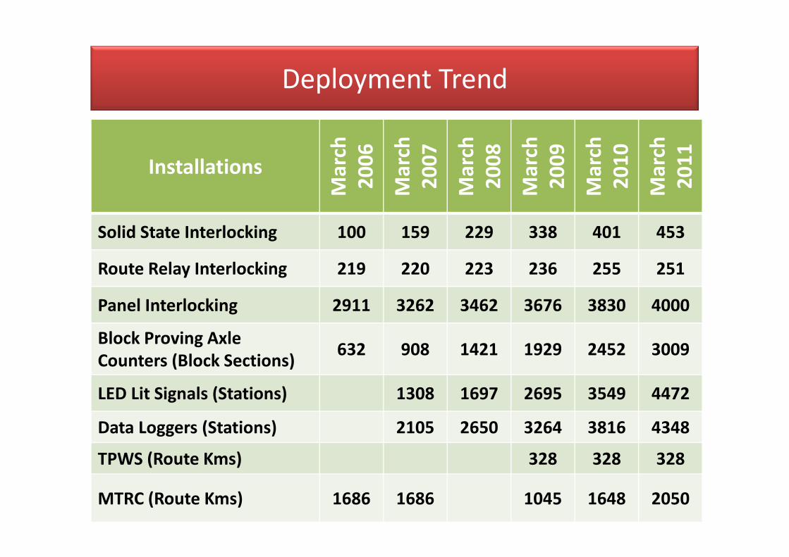
Installations
Ma
rch
20
06
Ma
rch
20
07
Ma
rch
20
08
Ma
rch
20
09
Ma
rch
20
10
Ma
rch
20
11
Solid State Interlocking 100 159 229 338 401 453
Route Relay Interlocking 219 220 223 236 255 251
Panel Interlocking 2911 3262 3462 3676 3830 4000
Block Proving Axle
Counters (Block Sections)632 908 1421 1929 2452 3009
LED Lit Signals (Stations) 1308 1697 2695 3549 4472
Data Loggers (Stations) 2105 2650 3264 3816 4348
TPWS (Route Kms) 328 328 328
MTRC (Route Kms) 1686 1686 1045 1648 2050
Deployment Trend
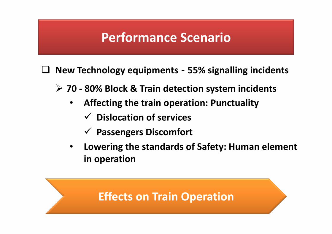
Performance Scenario
� New Technology equipments - 55% signalling incidents
� 70 - 80% Block & Train detection system incidents
• Affecting the train operation: Punctuality
� Dislocation of services
� Passengers Discomfort
• Lowering the standards of Safety: Human element
in operation
Effects on Train Operation

Trains Loosing Punctuality over the Zones
0
500
1000
1500
2000
2500
3000
3500
NR ECR NCR ER NER SR WCR CR SER SECR NFR WR SCR SWR ECoR NWRNo
. o
f Tr
ain
s Lo
osi
ng
Pu
nct
ua
l R
un
nin
g
Zones of Indian Railways
2010
2011

What has Changed?
Year 2004 2005 2006 2007 2008 2009 2010 2011
Expenditure (in
100 millions of
INR)
688.53 817.7 1042.5 1179.2 1343 1380 1048 958.5
Signal
Incidents (in
00)
117 124 115 148 168 141 123 119
Train Km
(Million)776 799 825 856 892 933 981 1022

What has Changed?
2004 2005 2006 2007 2008 2009 2010 2011
No. of Accidents Attributed
to Human Factor268 197 206 169 165 151 138 116
268
197206
169 165151
138
116
50
75
100
125
150
175
200
225
250
275
300
No
. o
f A
ccid
en
ts
YEAR
No. of Accidents Attributed due to Human Factor

New Technology Based Signalling Equipments
• Attributes:
• Proven all over the World
• BUT, Performance, Reliability & Availability not up
to the mark
• All systems have similar reliability Issues
• Status of few of the systems is presented

Electronic Interlocking (EI)
� First Trial installation back in 1987 in Southern zone
� Large scale deployment started in 2002 with first installation at Chakulia
station on Howrah – Mumbai route in South Eastern zone
� Cross Acceptance Procedure followed
� first major failure at Chakulia due to Lightening within three months of
installation
� Similar failures are continuing even after 10 years of research on
lightening & surge protection by the leading vendor
Zone PopulationFailures Per System
Per MonthMTBF (Hrs) Specified MTBF (Hrs)
ECR 3 0.0135 18136 > 1x10⁵
SCR 40 0.0031 5951* > 1x10⁵
SER 52 0.0012 11457 > 1x10⁵

Electronic Interlocking: Major Issues
� Competency in design, production, verification and
validation of application logic
� Damage occurred to the EIs from lightning and surges
� Non-availability of user-friendly diagnostic tools, flow
charts and event/ error logs
� Isolation of core EI equipments with outdoor
equipments

Digital Axle Counters (DAC)
� Analog Axle counters on the IR were introduced during the 1970s
� DACs were introduced in early 2000.
� DAC for block proving was introduced as part of the Corporate Safety
Plan (2003-2013)
� First technical specification for DAC was issued during 2003
� 2005-06 and onwards, Multi Section Digital Axle Counters (MSDAC) in
addition to SSDAC are increasingly used in the yards for train detection
purposes
Zone PopulationFailures Per System
Per MonthMTBF (Hrs) Specified MTBF (Hrs)
ECR 366 0.001 1975 > 1x10⁵
SCR 447 0.36/ 0.001 1631 > 1x10⁵
SER 292 0.0013 1815 > 1x10⁵

Digital Axle Counters (DAC)
BI, 26.9
TC, 15.8
Relay, 14.3
Cables, 9.1
Signal Lamps, 8.8
Miscellaneous, 6.5
Fuse Blown, 5.0
Lifting Barrier, 4.1
Maintainence Issues, 3.6
Power Equipments, 2.5EPM, 0.9 Interlocking, 0.3
� > 42% of signal incidents pertain to Block and Train Detection system
� Out of these 42% incidents, 80% of block and 69% of train detection
system incidents are due to the malfunctioning of DACs

Digital Axle Counters: Major Issues
� Software instability causing frequent hangs and no
response to the actions
� Component reliability enhancement
� Robust design of track devices
� Standard Wiring discipline to minimise the effect of EMI
and noise
� Lightening and surge protection
� Fault diagnostic flow charts and robust error logger

Train Protection & Warning System (TPWS)
� TPWS, similar to ETCS level 1 sanctioned for 52 Km of Chennai –
Gummidipundi section of Southern Railway (SR) and Delhi –
Mathura section of Northern Central Railway (NCR)
� TPWS in 50 Km section of SR commissioned on a trial in January
2008
� Many important issues coming in the way of its successful
functioning are yet to be resolved even after a lapse of more
than 4 years.
� Substantial modifications of the system during 2008 to 2011
� Efficiency ranging from 77% to 90% against the desired efficiency
of 99.9 %.
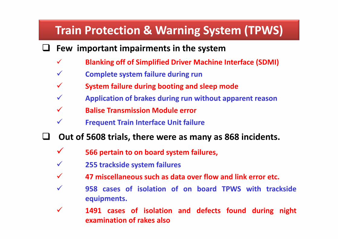
Train Protection & Warning System (TPWS)
� Few important impairments in the system
� Blanking off of Simplified Driver Machine Interface (SDMI)
� Complete system failure during run
� System failure during booting and sleep mode
� Application of brakes during run without apparent reason
� Balise Transmission Module error
� Frequent Train Interface Unit failure
� Out of 5608 trials, there were as many as 868 incidents.
� 566 pertain to on board system failures,
� 255 trackside system failures
� 47 miscellaneous such as data over flow and link error etc.
� 958 cases of isolation of on board TPWS with trackside
equipments.
� 1491 cases of isolation and defects found during night
examination of rakes also

LED Signals
� Introduced on IR during 1999 – 2000
� RDSO issued the draft specification in 1999 along with an approved list
of manufacturers
� Thrust during the execution of an overdue infrastructure replacement
works, financed by the Special Railway Safety Fund (SRSF) since 2002
� By 2007, more than 1300 stations i.e. around 22% stations were
provided with LED signals
� Great respite to the signalling maintenance management from
the pre-mature fusing of conventional lamps and frequent
replacement of signal lamps
� Large numbers of incidents started emerging due to non-picking up of
conventional ECRs used with LED signals causing failures
� Large scale failures of current regulators due to penetration of water
through improperly sealed colour light signal units

LED Signals: Performance & Issues
� Problems overshadowing the advantage provided by the new and
improved technology
Zone PopulationFailures Per System
Per MonthMTBF (Hrs) Specified MTBF (Hrs)
ECR 5028 0.0002 60876 > 1x10⁵
SCR 25939 0.0001 431318 > 1x10⁵
SER 10794 0.0003 606730 > 1x10⁵
� Major Issues:
• Non involvement of maintenance teams & interfaces
• Poor design & non-compatibility with environmental conditions
• Re-drafting of the specification to suit environmental conditions

Road Ahead
Sub optimal performance of these new
technology based signalling systems will add
problems to the Users, Maintainers and
Customers alike.
Therefore, a serious thought to improve the
Reliability and Availability of these systems is
required

Adopting Correct Approach of Induction
� Real benefit has not come to the Users and Maintainers of
the new technology
� Where Have We Slipped Up?
� Fundamental Difference between the two genres:
o Feel and See Through factors Vs Conceive, Measure and See
o Documentation of every stage of system Life Cycle for
understanding of the interfaces is must
o Technicians and Engineers with conventional engineering
backgrounds Vs altogether different approach, knowledge
and skill sets for the planning, implementation, operation
and maintainenece regime

Adopting Correct Approach of Induction
� System Life Cycle approach in contrast to the overlapping
design, installation and testing regime of old technology
based systems
� Comprehensive system of testing, installation and
maintenance to be evolved and nurtured
� Set up a core group having the specialization in the above-
mentioned areas
� Comprehensive methodology for testing to demonstrate
the compliances has to be specified
� Training of People involved in the process

Adopting Correct Approach of Induction
Design:
• Domain knowledge of Designers
Installation:
• Skill for handling of sensitive electronics components,
sub systems and software based systems
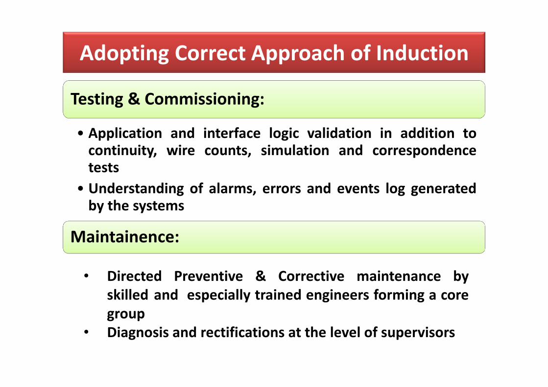
Adopting Correct Approach of Induction
Testing & Commissioning:
• Application and interface logic validation in addition tocontinuity, wire counts, simulation and correspondencetests
• Understanding of alarms, errors and events log generatedby the systems
Maintainence:
• Directed Preventive & Corrective maintenance by
skilled and especially trained engineers forming a core
group
• Diagnosis and rectifications at the level of supervisors
Adopting Correct Approach of Induction
Training:
• Complex with availability of few expert trainers
• Not only the system knowledge but special fault diagnostictechniques
• Understanding to decode the alarms, events and errors andcorrelate with the subsystems.

• Entire Novel Approach
• Training of the decision makers in assessment and validationtechniques
• Complex with availability of few expert trainers
• Not only the system knowledge but special fault diagnostictechniques
• Understanding to decode the Alarm, Event and Error logsand correlate with the systems, subsystems, cards andcomponents
• Keep these system-trained people in continuous touch withthe system
• The fear of attrition and conventional style of managementfor placement of trained staff must be given up
Training

• Clearly drafted Functional Requirements Specifications of
the system
• Parameters & methods to demonstrate the compliance of
EN50126, 50128, 50129 and 50121
• Comprehensive validation and cross acceptance documents
• System Safety case production and verification by
independent Assessor
• Documentation demonstrating the satisfactory performance
with lowest MTTR and highest MTBF, its verification by
independent assessor
Documentation

� Documentation provided by the manufacturers and
vendors:
� system schematic knowledge,
� sketchy installation and testing techniques,
� poor drafted & non-comprehensible fault diagnostics, flow
charts and manuals to decode and decipher the alarms,
events and errors
� even not understood by the staff of these vendors
� Not from the designer or manufacture perspective but
for the maintainenece technicians and engineers
Knowledge Sharing

Issues for IR Signalling
� Issues requiring attention to avoid the discredit to proven
technologies, improve the experience of customers and
working environment of maintenance management
� Mandate the process of making independent system and functional
requirement specification
� System Engineering and life cycle approach
� Documentation of EMI signatures of the existing systems
� Independent assessment and validation of the systems
� Robust Cross Acceptance process including Safety cases
� Change in working rules and procedures to supplement the system

Issues for IR Signalling
� Documented quality procedure to ensure the foolproof testing before
coming out of the manufacturing line
� Specifications providing for method of verification of compliances to
the provisions of standards like EN 50126, 50128, 50129 by the quality
check streams
� Training and skill building of people behind these systems
� Sanction of trial works on a limited scale
� large scale deployment only after documented and verified reliability
and availability figures after field trials

Conclusion
� An efficient and performing IR comparable to the
acceptable standards worldwide is the need of the hour to
provide fastest clean transport system for growing Indian
Economy. To achieve this goal, IR must
• put in place a robust new technology induction process
• ensure Competent, trained, skilled, motivated and confident pre-
acceptance quality check groups and in service maintenance
team
• involve all stakeholders and interfaces to achieve the designed
reliability and availability parameters of the new technology
based systems
• IRSE role

Thanks for your attention!