Embed Size (px)
Citation preview

1
PERFORMANCE OF MATERIALS IN BLACK LIQUOR GASIFICATION ENVIRONMENTS
James R. Keiser, Roberta A. Peascoe, James G. Hemrick,Camden R. Hubbard, Peter F. Tortorelli and Bruce A. Pint
Oak Ridge National LaboratoryP.O. Box 2008
Oak Ridge, TN [email protected]
ABSTRACT
Black liquor gasification systems have the potential to replace black liquor recoveryboilers because of their increased energy efficiency, reduced emission of pollutants andinherently safer designs. However, there are significant problems that must be addressed, notthe least of which is the selection of suitable materials for containment of the processesassociated with gasification. There are two systems that are considerably ahead of all others interms of development efforts and commercialization: a low-temperature process that operatesbelow the melting point of the salts and one that operates well above it. Descriptions of bothsystems and the operating environments are presented, as well as a summary of theperformance of materials in these systems. Laboratory studies that simulate the gasifierenvironments are currently underway, and initial results of these studies indicate there aresignificant materials issues to be resolved. Predictions of corrosion rate have also been madeusing proprietary software, and results of these projections are summarized.
Keywords: Black liquor, black liquor gasification, low temperature black liquor gasification, hightemperature black liquor gasification, oxidation, sulfidation
INTRODUCTION AND BACKGROUND
In North America, the kraft process is the predominant chemical method used toseparate the wood fibers in the pulping stage of papermaking. Black liquor, which is a by-product of this pulping process, is an aqueous solution containing both organic and inorganicmaterial. The organic material is derived from the unused portion of the wood and is generallyrecovered and burned in the recovery boiler to produce heat and steam. The inorganic materialis a result of the reaction between the pulping chemicals (sodium sulfide and sodium hydroxide)and the wood. The goal of the chemical recovery process in kraft mills is to regenerate thesepulping chemicals. The combustion of the organic material and recovery of the chemicals areaccomplished in a black liquor recovery boiler, but there are many shortcomings to thisapproach. These boilers are relatively inefficient with respect to production of steam andpower, have relatively high pollutant emission levels and present safety issues associated with

2
the molten salt produced in the boiler. Black liquor gasification offers an alternative to recoveryboilers, and a recent publication indicated that there are energy and financial benefits to begained by switching to gasification of black liquor. In addition to the kraft process, two less1
frequently used pulping processes, known as the “semi-chem process” and the “sulfiteprocess”, produce waste streams that can be gasified in the same fashion as the kraft blackliquor. The most significant difference is the sulfur content of the liquor: that from the semi-chem process has small or negligible amounts while liquor from the sulfite process containsabout twice the sulfur of kraft liquor.
Two black liquor gasification processes have been developed to the extent that anumber of pilot and/or demonstration scale units have been or are being built. These twoprocesses are fundamentally different. In the low temperature process developed byManufacturing and Technology Conversion International, Inc. of Baltimore, MD, steam2
reforming occurs in a fluidized bed where the temperature is currently limited to about 605°C.By keeping the temperature at or below this point, the alkali salts remain as solids rather thanmelting and forming a liquid phase that can attack the structural components as well as formdense plugs in the reformer/gasifier vessel. In the high temperature gasification processdeveloped by Chemrec AB, Stockholm, Sweden, the temperature of the process is maintained3
well above the melting point of the salt. As a result of the higher temperature operation,gasification reactions occur at a much higher rate, but a molten salt phase is formed and has tobe contained.
One issue that affects both gasification processes is an increase in the amount ofsodium carbonate that must be processed. When sulfur is removed from the gasifiers ashydrogen sulfide, the sodium that had been associated with the sulfur as sodium sulfide orsulfate is converted into sodium carbonate. This significantly increases the load on the lime kilnand associated process equipment. There are chemical processes currently being investigatedthat would address this causticization issue. At least one of these processes would increase4
the melting point of the salts so that the low temperature reformer/gasifier could operate about100 C° hotter, thus significantly improving the reaction kinetics.5
Both gasification processes have some very favorable attributes, but furtherdevelopment and implementation could be limited because of a common problem: containmentmaterials. In a previous paper, the material issues of each process were described, and someexamples of the active degradation mechanisms were given. Since that paper was written, a6
number of laboratory studies have been initiated and some degraded gasifier components havebeen examined. This paper will provide a brief description of the two processes and it willreview some of these recent studies.
Low-Temperature Black Liquor Gasification
Steam reforming of the black liquor is key to the low temperature process. In thisprocess, the temperature is kept low enough that the alkali salts, commonly referred to assmelt, does not become molten or even reach the point where it becomes “sticky”. A typicalreformer/gasifier system is shown in Fig. 1. This system utilizes a fluidized bed of sodiumcarbonate particles. Steam introduced through the bottom of the vessel serves as the fluidizinggas as well as the source of water for the reforming operation. The black liquor is introducedthrough a nozzle system, also located on the bottom of the vessel. Heat is transferred to thebed through several tube modules (each containing hundreds of tubes) that carry hotcombustion gas. The hot gas is produced in the refractory lined combustion chambers wherethe fuel, either “clean” product gas or an auxiliary fuel, is burned in a pulsed combustion mode.

3
Heat from the combustion gases is transferred through the walls of the pulsed heater bed tubesto the bed material where the reforming operation occurs.
A demonstration scale gasifier utilizing the low temperature process was installed in1994 at a paper mill in New Bern, North Carolina. This unit successfully completed a continuous500 h run on black liquor during August, 1995. Currently, full-scale reformer/gasifier facilities2
are under construction at mills in Big Island, Virginia, and in Trenton, Ontario. Neither of thesemills operates on the kraft process; they utilize the semi-chemical sodium carbonate cookingprocess for treating the wood chips, so the absence of significant amounts of sulfur compoundsis expected to make the environments less hostile for the structural materials. Nevertheless,these installations will provide an opportunity for a more thorough evaluation of this process.
High-Temperature Black Liquor Gasification
The high-temperature gasification process can be operated near atmospheric pressureor at significantly elevated pressure. The lower pressure version of this system is generallyenvisioned as a supplement to recovery boilers, while the high-pressure version is expected tototally replace recovery boilers for processing of the black liquor.
High-temperature, low-pressure gasification. A schematic diagram of the high-temperature, low-pressure (HTLP) gasifier is shown in Fig. 2. In this refractory-lined vessel, theblack liquor fuel, steam and air for partial combustion of the liquor are injected at the top of thevessel. The organic material contained in the black liquor is gasified, and the inorganic saltsare left in the liquid state, primarily on the gasifier wall. The liquid and gaseous products areremoved through the bottom of the gasifier vessel. The product gas is routed through a gasclean-up system and the inorganic salts are directed to the green liquor tank. A 75 tons drysolids (tds)/day demonstration system was operated in Sweden in the early 1990s. A 3307
tds/day gasifier of this type was put into service in 1996 at the mill in New Bern, North Carolina;8
it was taken out of operation in December, 1999 because of problems with the structuralmaterials. Operation of the New Bern gasifier resumed near the end of June, 2003.
High-temperature, high-pressure gasification. There is limited experience with high-temperature, high-pressure (HTHP) black liquor gasification. A 10 tds/day pilot scale unit wasoperated in Sweden from 1994 through 2000. The unit operated continuously for an extended9
period, but only daytime operation was on black liquor; the system was switched to fuel oil whenit was unattended. A total of about 1000 h of operation was accumulated on black liquor feedwhile the system operated for a considerably longer time on fuel oil. Samples of refractory linerfrom this system have been examined. A limited amount of refractory degradation was6
observed and this was consistent with that subsequently seen in refractory removed from theNew Bern gasifier.6
There are two competing designs being considered for the HTHP gasifier. One designutilizes a thick refractory lining within a metal pressure vessel. This design was used in theSwedish gasifier and has a refractory lining similar to that shown in Fig. 2 for the HTLP gasifier. The alternative design, called a cooling screen, utilizes a helically-coiled metal tube that has arefractory surface coating (see Fig. 3) and circulates pressurized cooling water. A similardesign has been used successfully with the slag produced during coal gasification, but it hasnot yet been proven with the molten smelt produced during the high temperature gasification ofblack liquor. Currently, a HTHP demonstration scale unit is under construction in the town ofPiteå in northern Sweden. Operation is not expected to begin before summer 2004. Both thethick refractory lining and the cooling screen designs will be tested.

4
OPERATING CONDITIONS AND MATERIAL CHOICES
Low-Temperature, Black Liquor Gasification
The low-temperature black liquor steam reformer/gasifier presents a range of conditionsfor which materials have to be selected. The highest temperature region is the pulse-combustion chamber where temperatures are expected to reach 1300-1500°C. The carbonsteel chamber is lined with refractory insulation in order to contain the hot combustion gases. The refractory being used in at least one of the systems under construction is a high-alumina
2 3 2extra-low cement pumpable castable that contains 60% Al O , 36.3% SiO , 0.6% CaO and
21.6% TiO . If the product gas is used as fuel for the combustor and if problems were to developin the gas clean-up system, contaminants in the fuel could be detrimental to the refractory. Designers of future systems will have to determine whether to consider the possibility of fuelcontaminants when the refractory material is being selected for systems processing black liquorcontaining a significant amount of sulfur compounds.
It is expected that about 90% of the combustion will occur in the combustion chamber,while the remaining fuel is burned in the first section of the bed tubes. In order to prevent heatgenerated during this last stage of combustion from raising the bed tube temperature above thesodium carbonate melting point, a short length of tube, called a shield tube, is used inside thefirst portion of each bed tube. This shield tube should be fabricated from a material withsufficient corrosion resistance to survive in the hot combustion gas that includes oxygen,moisture, and possibly contaminants from the fuel. Materials being utilized in the systemsunder construction include high-chromium content stainless steels or more highly-alloyed“super” stainless steels like N08330 and N08810.
The pulsed-heater tubes that provide heat to the bed are exposed to hot combustiongases on the inside and the product gas and bed material on the outside. As with the shieldtubes, the insides of the bed tubes are exposed to an atmosphere containing oxygen, moistureand possible contaminants, but at a lower temperature than experienced by the shield tubes. The outside of the bed tubes is exposed to an atmosphere that contains hydrogen, moisture,carbon monoxide and carbon dioxide at a temperature of about 605°C. If the liquor beingprocessed is from a kraft or sulfite mill, significant amounts of hydrogen sulfide will also bepresent in the reformer atmosphere, and this will appreciably increase the aggressiveness ofthe environment. For a gasifier/reformer processing liquor from a semi-chem process mill, thebed atmosphere is expected to be sufficiently benign that a stabilized stainless steel like typesS32100 or S34700 should provide adequate corrosion resistance. Because the operatingtemperature is in the range where sensitization could occur, it is essential to use an alloy thatwill not become susceptible to intergranular attack. When liquor from a kraft or sulfite mill isprocessed, the hydrogen sulfide in the environment will require the bed tubes to havesignificantly greater corrosion resistance. Thermodynamic calculations suggest that alloysexposed to this environment should have no more than a limited amount of nickel (probably<15%) and sufficient chromium and/or aluminum to form a surface oxide that providesadequate resistance to sulfur penetration. The mechanical motion of the sodium carbonate bedparticles on the bed tubes could accelerate degradation by damaging or removing protectivescales, but no data exist on the effects of long-term exposures on tubes to this environment.
The carbon steel or low-alloy reformer/gasifier vessel is lined with refractory to provideprotection from thermal, chemical, and mechanical effects of the bed environment. Differentrefractories are used in the bed area and the freeboard area. In one of the systems currently
2 3 2under construction, refractories for both areas are nominally 44-45% Al O , 38% SiO , 13-14%
5
CaO and 0.2-0.4% MgO. However, the bed refractory has a crush strength at 815°C that isabout six times that used in the freeboard area [56.9 vs 8.3 MPa (8,250 vs 1,200 psi)].
High-Temperature Black Liquor Gasification
As noted previously, the high-temperature gasification process can be operated nearatmospheric pressure or at significantly elevated pressure. Furthermore, there are two designsbeing considered for the elevated-pressure version. Consequently, there are severalenvironments that have to be considered in identifying suitable materials for high-temperatureblack liquor gasifiers.
High-temperature, low-pressure gasification. The design currently used for the singleexisting gasifier of this type, as well as that expected to be used in any future gasifiers of thiskind, has a thick refractory brick lining inside a metal shell. As shown in Fig. 2, this is acylindrical vessel and the refractory bricks have to be fabricated to form the conical shape atthe bottom, the cylindrical section in the midsection, and the dome at the top of the gasifiervessel. The refractory initially used for the lining was a bonded alumina-silica brick. This10
material showed unacceptably rapid degradation, so a replacement of fusion-cast alpha/betaalumina was installed. This material degraded less rapidly, but the rate was still unacceptablyhigh. The shell of the gasifier was originally constructed of 316L stainless steel, but extensivecracking developed because of chloride stress corrosion. Carbon steel was used for thereplacement shell that is currently in use. When the gasifier was restarted in late June, fusion-cast alpha/beta alumina from an alternate manufacturer was installed.
High-temperature, high-pressure gasification. As noted previously, there are twodesigns being evaluated for the high-pressure gasifier; a solid refractory brick lining and thecooling screen design. There is very limited experience with high-pressure gasification; theSwedish pilot-scale system utilized a refractory brick lining made of fusion-cast, alpha/betaalumina. The cumulative operating time on black liquor was limited to about six weeks, butchemical phases were identified on the refractory surface that were the same as thedegradation products found on the fusion cast alpha/beta alumina exposed in the New Bern lowpressure gasifier. As with the low pressure gasifier, less expensive and/or longer liferefractories will be required if this gasifier design is to be successfully commercialized.
The cooling screen concept has been successfully employed in coal gasification, butthere is essentially no experience with this design in black liquor gasification. In addition tofinding a refractory that has the appropriate thermal conductivity and corrosion resistance, therefractory will need to have a coefficient of thermal expansion such that it will remain in goodthermal contact with the helically-coiled, metallic tube to which it is applied.
EXPERIMENTAL STUDIES
Low-Temperature Black Liquor Gasification
Studies are underway to assess the corrosion resistance of selected alloys inenvironments characteristic of those in low temperature gasifiers. Specifically, laboratory testsare being conducted at temperatures and in oxygen and sulfur partial pressures expected for 1)the bed tubes in a reformer/gasifier that is processing kraft black liquor, 2) the bed tubes in areformer/gasifier processing sulfite black liquor, 3) the shield tubes in a reformer/gasifieroperating in a mill where fuel contaminants are minimal and 4) the bed tubes in areformer/gasifier processing kraft black liquor where the temperature is 100 C° higher as a

6
result of the switch to one of the alternate processes involving the use of titanates. 4
Identification and composition of alloys used in corrosion studies and in corrosion ratecalculations are given in Table 1.
Results of the first 200 h of corrosion tests of alternate bed tube materials in the gasexpected in a reformer/gasifier processing kraft black liquor are summarized in Table 2 andshown graphically in Fig. 4, and they reveal that some of the commonly used alloys experiencesignificant rates of degradation. Another test providing important results is evaluating potentialshield tube materials at 1000 and 1100°C in oxidizing environments that are cooled to roomtemperature every 100 or 500 h. The results, presented in Fig. 5, suggest that most chromia-forming alloys, like those being used in the systems under construction, may experienceconsiderable corrosion if the tests with some thermal cycling give a representative indication ofthe corrosion that will be experienced in the actual systems.
High-Temperature Black Liquor Gasification
High-temperature, low-pressure black liquor gasification. A laboratory test system hasbeen constructed that successfully reproduces the corrosion products observed to form onrefractories that were exposed in operating gasifiers. Using this system, extensive laboratory6,11
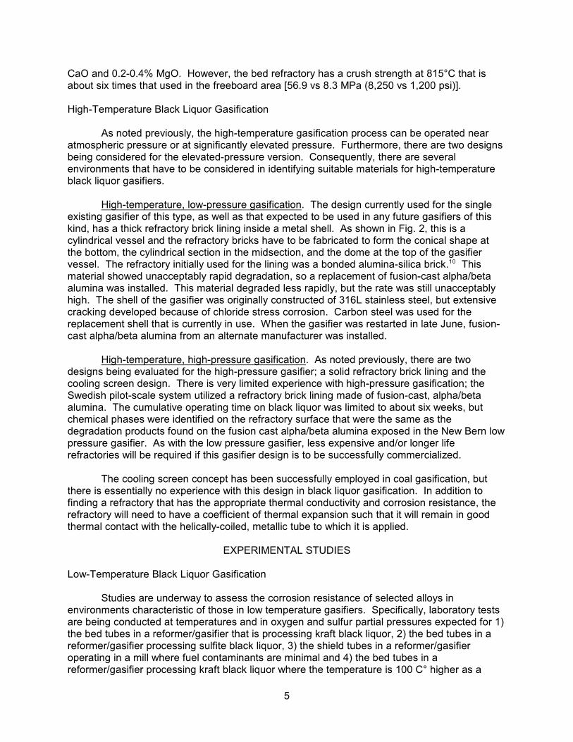
studies have been conducted to evaluate the resistance of a large number of refractories todegradation by the molten salt collected from a black liquor recovery boiler. These studieshave shown that certain surface treatments can be used to improve the resistance of a numberof refractories to molten smelt. Improved corrosion resistance can result from creation of asurface layer by reaction with an added material to form a new phase, or it can be the result ofchemical or microstructural modifications of the surface, made before exposure. An example ofthe improvement in corrosion resistance as a result of modifications that form a new phase areshown in Fig. 6. The photo on the left side shows a cross-section of a mullite-based refractoryafter immersion in molten smelt at 1000°C for 50 h. The dark material around the outside of12
the sample is the corrosion product from reaction of the refractory with the smelt. The photo on
2 3the right shows a cross-section of the same refractory that had been treated with Li O followedby a heat treatment prior to exposure in molten smelt under the same conditions. The reactionof the lithium compound with the alumina and/or silica in the refractory formed a glassy surfacelayer that improved the resistance of the refractory to smelt penetration.
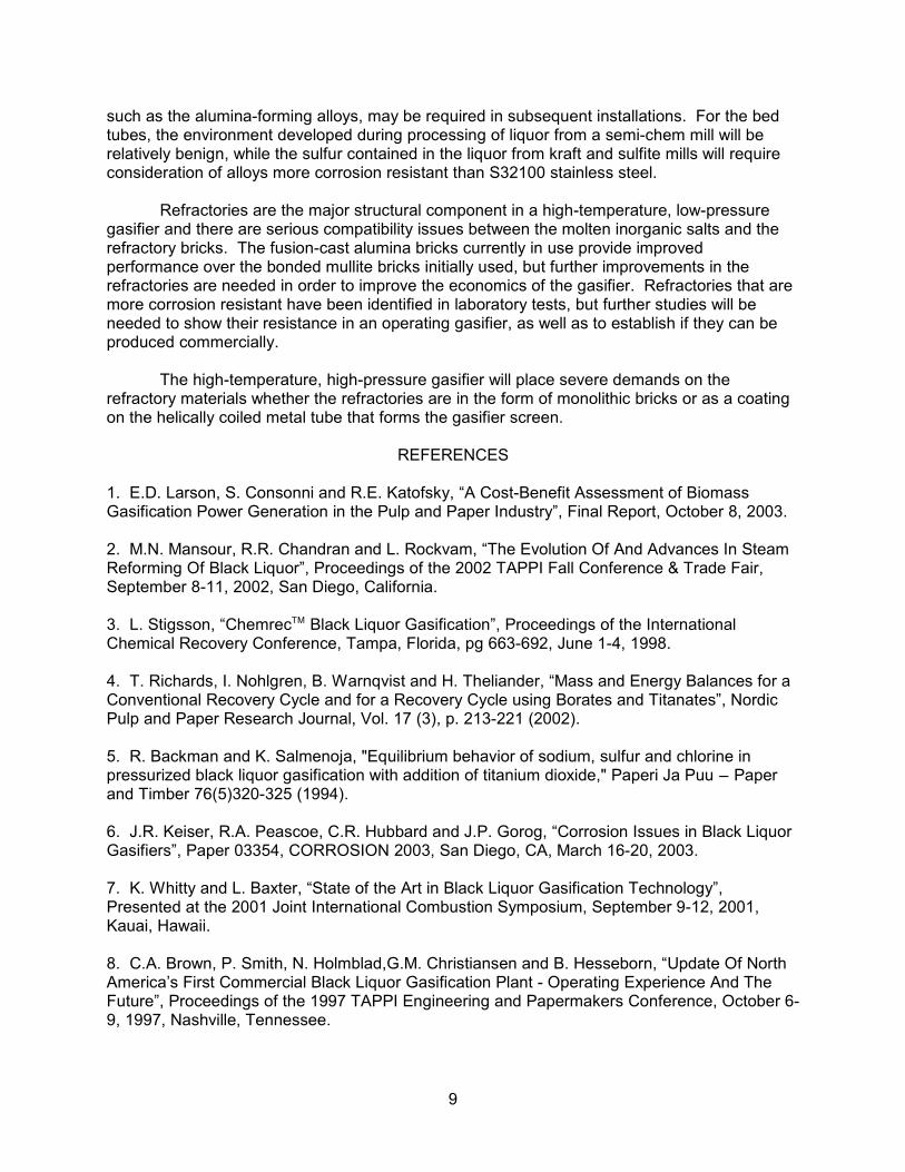
Studies of fusion-cast refractories have shown that the as-cast surface can promote orinhibit penetration of smelt. Figure 7 shows a cross-section of such a refractory where the12
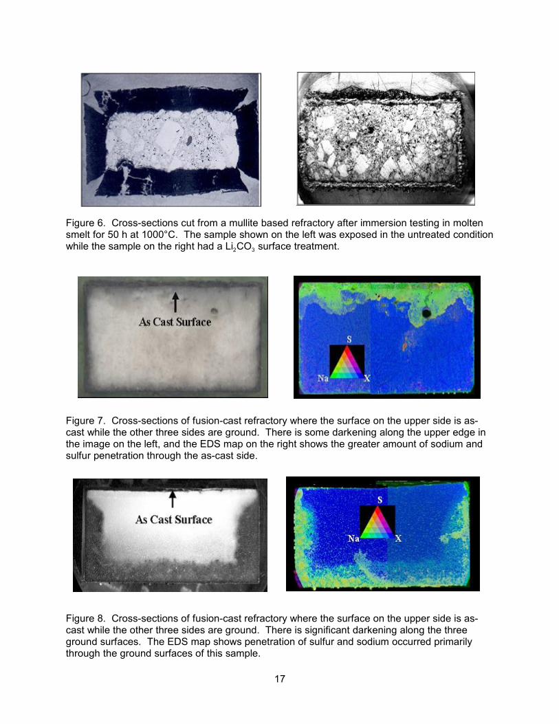
surface along the upper side of the photo is as-cast, while the other three sides have beenground to fabricate the sample. The image on the right gives an indication of the compositionof the refractory after exposure at 1000°C for 100 h in molten smelt. It is clear that in this case,penetration of smelt components proceeds more rapidly through the as-cast surface thanthrough the ground surfaces. The fusion-cast refractory shown in Fig. 8 which also has the as-cast surface along the upper side of the photo, showed the opposite effect. As indicated by thedarkening in the photo on the left and by the elemental maps in the image on the right, in thisrefractory smelt components penetrated much more rapidly through the ground surfaces thanthrough the as-cast surface. Studies have shown there are significant compositional andmicrostructural differences between the as-cast surfaces and the bulk material in each of thesetwo refractory samples, and work is in progress to reproduce these phenomena in a controlledway.
In addition to the examples just described, characterization studies are underway onsamples of a bonded refractory that has an intercrystalline phase that appears to have

7
unusually good resistance to molten smelt and on samples of several refractories that have hadtheir surfaces treated with a high-intensity plasma-arc lamp. In both cases, improvedresistance to penetration by sodium and sulfur has been observed in laboratory immersiontests.
To complement the refractory corrosion tests, studies in molten salts have beenconducted on a series of high-chromium alloys being developed specifically for their resistanceto the sodium salts. Studies show that these alloys have resistance to smelt degradation that issignificantly better than that of a nominal 50% Cr-50% Ni alloy that is similar to materials thathave been used in molten smelt service. Currently, a sample of one of the high-chromium13
content alloys is being exposed in the New Bern gasifier.
High-temperature, high-pressure black liquor gasifier. There is an apparent absence ofexperimental data on the stability of refractory and metallic materials in molten smelt at highpressures. It is expected that the refractory studies being conducted for the HTLP gasifier willhave some relevance to HTHP gasifiers. However, since the effect of pressure on thethermodynamic equilibrium and reaction kinetics is not known for the reaction of smelt withrefractory and metallic materials, some caution has to be used in applying the results of near-atmospheric pressure corrosion studies to elevated pressure.
CORROSION RATE PREDICTIONS
Low-Temperature Black Liquor Gasification
As another means to provide some guidance in the selection of metallic materials for thenew gasifier systems, software designed for alloy selection for service at elevated temperature(ASSET) has been used. This software utilizes an extensive data base that was compiled14
from a large number of corrosion studies of commercial alloys. The software can predictcorrosion rates as a function of temperature as well as the partial pressures of oxygen andsulfur in gaseous environments considered to be oxidizing or oxidizing-sulfidizing. This hasbeen particularly useful for the low-temperature reformer/gasifier where the primary corrodentsare gaseous species rather than liquid as is the case for the high-temperature systems. Unfortunately not all alloys that should be considered for this application are included in thedata base, so that alloys of similar composition are used to get an estimate for the corrosionrate of some alloys.
There are some considerations that have to be addressed when using these calculatedcorrosion rates to make an alloy recommendation. First, where the equilibrium calculationsmade by ASSET indicate the formation of a molten phase, any predicted corrosion rages areflagged as not valid. This is particularly relevant for exposure of some of the high-nickelcontent alloys in a sulfidizing environment above about 660°C. Other issues that have to beconsidered in making an alloy selection are the properties (particularly strength) at servicetemperature, the alloy’s fabricability, the capability of the alloy to be welded and the availabilityof the alloy in the desired product form.
Corrosion rate predictions have been made for 1) the screen tubes in the hightemperature combustion gas environment, 2) bed tubes in the product gas from reforming ofkraft black liquor at 605°C (tube temperature assumed to be 675°C), 3) bed tubes in theproduct gas from reforming of kraft black liquor at 705°C (tube temperature assumed to be775°C), and 4) bed tubes in the product gas from reforming of sulfite mill black liquor.

8
Examples of the corrosion rates predicted for the high-temperature, oxidizing,combustion gas environment are shown in Table 3. It should be noted that the large error barsassociated with some of these predicted corrosion rates result from the fact that the corrosiondatabase considers the maximum depth of corrosion penetration, which can vary considerablyamong alloys. These results indicate that an alumina-former or a fairly highly alloyed chromia-forming material should be considered for the shield tubes, particularly since corrosion willoccur on both sides of the tubes. In fact, the volatility of chromia at the anticipated combustiongas temperatures could make use of chromia-forming alloys questionable.
The calculated corrosion rates for bed tubes in a reformer operating on kraft liquor(sulfidizing/oxidizing environment) at a nominal temperature of 605°C are given in Table 4. These results suggest that S32100 stainless steel that is appropriate for a semi-chem processliquor may also have adequate corrosion resistance for kraft liquor at 675°C. However, theissue of strength at operating conditions would be a major concern. It is important to note thatthe predicted corrosion rates for higher nickel-content alloys were high.
Table 5 lists the predicted corrosion rates for bed tubes in a reformer operating on kraftliquor (sulfidizing/oxidizing environment) but at a temperature of 775°C. For this application, analloy that forms an alumina scale, or more highly-alloyed materials, will be required than for thesimilar conditions at a lower temperature. Many of the nickel-base alloys that might normally besuggested for a harsh environment at this temperature are not suitable because they wouldform a liquid sulfide product under these conditions. The alloys that would be expected to forma low-melting nickel sulfide are indicated by an asterisk in the table.
The corrosion rates calculated for the environment that would be present in a reformerprocessing sulfite liquor (sulfidizing/oxidizing environment) are shown in Table 6. These resultsshow the higher-sulfur concentration makes this a very harsh environment. Because the tubetemperature will be very near the melting point of nickel sulfide, the higher nickel-content alloysshown in Tables 4 and 6 could be susceptible to rapid degradation. As the results indicate,there will be some problems in finding an affordable alloy that has sufficient corrosionresistance and can be welded and fabricated into the required forms.
High-Temperature Black Liquor Gasification
Corrosion rate calculations have not been made for the high-temperature gasifiersystems since there would be very few metallic components exposed to the molten smelt, anddata bases for corrosion by molten salts are not very extensive for these environmentalconditions.
SUMMARY AND CONCLUSIONS
There are two significantly different processes being developed for the gasification ofblack liquor. One process operates below the melting point of the inorganic constituents, whilethe second process operates well above it. Both processes share the common problem offinding suitable containment materials.
For the low-temperature reformer/gasifier systems currently under construction at themills operating on the semi-chem process, the bed tubes are constructed of S32100 stainlesssteel, while N08810 and N08330 stainless steel are being used for the shield tubes. Laboratorystudies suggest that the combustion gas temperature experienced by the shield tubes couldseverely degrade the alloys being used, and alloys designed for higher temperature service,
9
such as the alumina-forming alloys, may be required in subsequent installations. For the bedtubes, the environment developed during processing of liquor from a semi-chem mill will berelatively benign, while the sulfur contained in the liquor from kraft and sulfite mills will requireconsideration of alloys more corrosion resistant than S32100 stainless steel.
Refractories are the major structural component in a high-temperature, low-pressuregasifier and there are serious compatibility issues between the molten inorganic salts and therefractory bricks. The fusion-cast alumina bricks currently in use provide improvedperformance over the bonded mullite bricks initially used, but further improvements in therefractories are needed in order to improve the economics of the gasifier. Refractories that aremore corrosion resistant have been identified in laboratory tests, but further studies will beneeded to show their resistance in an operating gasifier, as well as to establish if they can beproduced commercially.
The high-temperature, high-pressure gasifier will place severe demands on therefractory materials whether the refractories are in the form of monolithic bricks or as a coatingon the helically coiled metal tube that forms the gasifier screen.
REFERENCES
1. E.D. Larson, S. Consonni and R.E. Katofsky, “A Cost-Benefit Assessment of BiomassGasification Power Generation in the Pulp and Paper Industry”, Final Report, October 8, 2003.
2. M.N. Mansour, R.R. Chandran and L. Rockvam, “The Evolution Of And Advances In SteamReforming Of Black Liquor”, Proceedings of the 2002 TAPPI Fall Conference & Trade Fair,September 8-11, 2002, San Diego, California.
3. L. Stigsson, “Chemrec Black Liquor Gasification”, Proceedings of the InternationalTM
Chemical Recovery Conference, Tampa, Florida, pg 663-692, June 1-4, 1998.
4. T. Richards, I. Nohlgren, B. Warnqvist and H. Theliander, “Mass and Energy Balances for aConventional Recovery Cycle and for a Recovery Cycle using Borates and Titanates”, NordicPulp and Paper Research Journal, Vol. 17 (3), p. 213-221 (2002).
5. R. Backman and K. Salmenoja, "Equilibrium behavior of sodium, sulfur and chlorine inpressurized black liquor gasification with addition of titanium dioxide," Paperi Ja Puu n Paperand Timber 76(5)320-325 (1994).
6. J.R. Keiser, R.A. Peascoe, C.R. Hubbard and J.P. Gorog, “Corrosion Issues in Black LiquorGasifiers”, Paper 03354, CORROSION 2003, San Diego, CA, March 16-20, 2003.
7. K. Whitty and L. Baxter, “State of the Art in Black Liquor Gasification Technology”,Presented at the 2001 Joint International Combustion Symposium, September 9-12, 2001,Kauai, Hawaii.
8. C.A. Brown, P. Smith, N. Holmblad,G.M. Christiansen and B. Hesseborn, “Update Of NorthAmerica’s First Commercial Black Liquor Gasification Plant - Operating Experience And TheFuture”, Proceedings of the 1997 TAPPI Engineering and Papermakers Conference, October 6-9, 1997, Nashville, Tennessee.

10
9. K. Whitty and A. Nilsson, “Experience From A High Temperature, Pressurized Black LiquorGasification Pilot Plant”, Proceedings of the International Chemical Recovery Conference,Whistler, British Columbia, pg 281-287, June 11-14, 2001.
10. C.A. Brown and W.D. Hunter, “Operating Experience At North America’s First CommercialBlack Liquor Gasification Plant”, Proceedings of the International Chemical RecoveryConference, Tampa, Florida, pg 655-662, June 1-4, 1998.
11. R.A.Peascoe, J.R. Keiser, C.R. Hubbard, J.P. Gorog, C.A. Brown and B. Nilsson,“Comparison Of Refractory Performance In Black Liquor Gasifiers And A Smelt Test System”,Proceedings of the International Chemical Recovery Conference, Whistler, British Columbia, pg297-300, June 11-14, 2001.
12. R.A. Peascoe, J.R. Keiser, J.G. Hemrick, M.P. Brady, P. Sachenko, C.R. Hubbard, R.D.Ott, C.A. Blue and J.P. Gorog, “Materials Issues in High Temperature Black LiquorGasification”, 2003 TAPPI Fall Technical Conference, Chicago, IL, October 26-30, 2003.
13. R.A. Peascoe, J.R. Keiser, C.R. Hubbard, and M.P. Brady, “Performance of SelectedMaterials in Molten Alkali Salts”, in Proceedings of the 10 International Symposium onth
Corrosion in the Pulp and Paper Industry, Valtion Teknillinen Tutkimuskeskus (VTT), Espoo,Finland, pp. 189-200 (2001).
14. R.C. John, A.D. Pelton, S. Decterov, A.L. Young, P. Spencer, W.T. Thompson, I.G. Wrightand T.M. Besmann, “Predictions of Corrosion Products for Alloys Corroding in Complex Gasesvia Thermochemical Analyses”, Paper 03501, CORROSION 2003, San Diego, CA, March 16-20, 2003.
ACKNOWLEDGMENTS
The authors wish to acknowledge the contributions of information and materials by RaviChandran and Lee Rockvam of MTCI/ThermoChem, Peter Gorog, Ray Leary and Craig Brownof Weyerhaeuser, Ingvar Landalv of Chemrec, Robert DeCarrera of Georgia-Pacific and BobRowbottom of Norampac. The laboratory corrosion tests were ably conducted by AdamWilloughby, George Garner and Mike Howell. Ian G. Wright and Dane F. Wilson providedtechnical reviews of the manuscript and Kim Choudhury prepared the final manuscript.
Research sponsored by the U.S. Department of Energy, Assistant Secretary for EnergyEfficiency and Renewable Energy, Office of Biomass Program and Industrial TechnologiesProgram, Industrial Materials for the Future. Oak Ridge National Laboratory is managed byUT-Battelle, LLC, for the U.S. Department of Energy under contract DE-AC05-00OR22725.

11
TABLE 1Identification and composition of alloys used in corrosion studies.
UNSNumber
AlloyIdentification
Ni Cr Fe Al Si C Other
N06025 602 CA 63 25 9 2.2 0.18 0.08 Y, 0.08 Zr
N06045 45 TM 46 27 23 2.8 0.09
N06230 230 60 22 1 0.3 0.4 0.10 0.02 La, 0.004 B
N07214 214 76 16 3.5 4.5 0.04 0.03 Zr, 0.005 Y
N08120 HR 120 37 25 35 0.1 0.6 0.05 0.7 Nb, 0.1 Ti, 0.004 B
N08330 330 SS 35 19 43 1.2 0.05
N08810 800H 31 21 45 0.3 0.4 0.06 0.4 Ti
N12160 HR 160 36 28 2 2.8 0.05 30 Co, 0.5 Ti, 0.5 Mn
R30556 Haynes 556 21 22 29 0.3 0.1 18 Co, 2.5 W, 0.2 N, 0.02 La, 0.6 Ta
S30815 253 MA 11 21 65 1.7 0.08 0.17 N, 0.04 Ce
S31008 310 SS 20 25 52 0.5 0.05
S32100 321 SS 9 17 70 0.7 0.01 0.2 Ti
S34700 347 SS 9.5 17 70 0.7 0.04 0.5 Nb
S35315 353 MA 35 25 36 1.2 0.05 0.16 N, 0.05 Ce
2 3S67956 MA956 20 74 4.5 0.1 0.02 0.5 Ti, 0.5 Y O
-- Incoloy DS 37 17 44 2.3 0.06

12
TABLE 2Mass change after two100 h cycles of selected alloys at 675°C in a steam reformer
environment during reforming/gasification of kraft black liquor
UNSNumber
Ni Cr Fe Al Si C Other Mass Gain(mg)
N06025 63 25 9 2.2 0.18 0.08 Y, 0.08 Zr 0.77
N06045 46 27 23 2.8 0.09 3.75
R30556 21 22 29 0.3 0.1 18 Co, 2.5 W, 0.6 Ta, 0.02 La
7.91
S35315 35 25 36 1.2 0.05 0.16 N, 0.05 Ce 4.81
N08120 37 25 35 0.1 0.6 0.05 0.7 Nb, 0.1 Ti,0.004 B
6.42
N12160 36 28 2 2.8 0.05 30 Co, 0.5 Ti 3.72
2 3S67956 20 74 4.5 0.1 0.02 0.5 Ti, 0.5 Y O 2.10
N08810 31 21 45 0.3 0.4 0.06 0.4 Ti 38.4
N08330 35 19 43 1.2 0.05 14.3
S32100 9 17 70 0.7 0.01 0.2 Ti 9.65
N07214 76 16 3.5 4.5 0.04 0.03 Zr, 0.005 Y **
** Large scale build-up; some material lost in removing sample from holder

13
TABLE 3Calculated corrosion rates for alloys exposed in the combustion gas (shield tube) environment of a low-
temperature reformer/gasifier at 1100°C.
Alloy UNSNumber
Ni Cr Fe Al Si C Other Corrosion Rate (mm/yr)8800 h 18000 h
2 3S67956 20 74 4.5 0.1 0.02 0.5 Ti, 0.5 Y O 0.03 ± 0.18 0.04 ± 0.26
R30556 21 22 29 0.3 0.1 18 Co, 0.02 La 0.30 ± 0.16 0.42 ± 0.24
N07214 76 16 3.5 4.5 0.04 0.03 Zr, 0.005 Y 0.33 ± 0.31 0.47 ± 0.44
N06025 63 25 9 2.2 0.18 0.08 Y, 0.08 Zr 0.34 ± 15.7 0.48 ± 22.4
S30815 11 21 65 1.7 0.08 0.17 N, 0.04 Ce 0.34 ± 0.55 0.49 ± 0.79
N06230 60 22 1 0.3 0.4 0.10 14 W, 0.02 La 0.47 ± 0.20 0.67 ± 0.29
S31008 20 25 52 0.5 0.05 0.69 ± 0.35 0.99 ± 0.50
N12160 36 28 2 2.8 0.05 30 Co, 0.5 Ti 0.98 ± 0.52 1.41 ± 0.75
N08810 31 21 45 0.3 0.4 0.06 0.4 Ti 1.11 ± 0.69 1.59 ± 0.99
S32100 9 17 70 0.7 0.01 0.2 Ti 1.55 ± 2.07 2.21 ± 2.95
S34700 9.5 17 70 0.7 0.04 0.5 Nb 2.01 ± 8.35 2.88 ± 11.9
TABLE 4Calculated corrosion rates for alloys exposed as bed tubes in the product gas from reforming of kraft
black liquor at 605°C (tube temperature assumed to be 675°C).
Alloy UNSNumber
Ni Cr Fe Al Si C Other Corrosion Rate (mm/yr)8800 h 18000 h
2 3S67956 20 74 4.5 0.1 0.02 0.5 Ti, 0.5 Y O 0.02 ± 0.24 0.03 ± 0.34
S34700 9.5 17 70 0.7 0.04 0.5 Nb 0.07 ± 0.30 0.10 ± 0.41
S31008 20 25 52 0.5 0.05 0.12 ± 0.12 0.18 ± 0.18
N12160 36 28 2 2.8 0.05 30 Co, o.5 Ti 0.13 ± 1.10 0.18 ± 1.59
N08120 37 25 35 0.1 0.6 0.05 0.7 Nb, 0.1 Ti 0.15 ± 0.17 0.21 ± 0.24
S30815 11 21 65 1.7 0.08 0.17 N, 0.04 Ce 0.16 ± 0.29 0.22 ± 0.42
N08810 31 21 45 0.3 0.4 0.06 0.4 Ti 0.18 ± 0.14 0.26 ± 0.19
N06025 63 25 9 2.2 0.18 0.08 Zr, 0.08 Y 0.46 ± 0.21 0.65 ± 0.30
R30556 21 22 29 0.3 0.1 18 Co, 0.02 La 0.56 ± 0.69 0.79 ± 0.98
N07214 76 16 3.5 4.5 0.04 0.03 Zr, 0.005 Y 2.70 ± 0.94 3.90 ± 1.30

14
TABLE 5Calculated corrosion rates for alloys exposed as bed tubes in the product gas from reforming of kraft
black liquor at 705°C (tube temperature assumed to be 775°C).
Alloy UNSNumber
Ni Cr Fe Al Si C Other Corrosion Rate (mm/yr)8800 h 18000 h
2 3S67956 20 74 4.5 0.1 0.02 0.5 Ti, 0.5 Y O 0.02 ± 0.27 0.03 ± 0.40
S34700 9.5 17 70 0.7 0.04 0.5 Nb 0.15 ± 0.64 0.22 ± 0.92
S31008 * 20 25 52 0.5 0.05 0.26 ± 0.26 0.38 ± 0.38
N08120 * 37 25 35 0.1 0.6 0.05 0.7 Nb, 0.1 Ti 0.27 ± 0.30 0.38 ± 0.43
N12160 * 36 28 2 2.8 0.05 30 Co, 0.5 Ti 0.28 ± 2.47 0.40 ± 3.53
S30815 11 21 65 1.7 0.08 0.17 N, 0.04 Ce 0.32 ± 0.60 0.46 ± 0.86
N08810 * 31 21 45 0.3 0.4 0.06 0.4 Ti 0.33 ± 0.24 0.47 ± 0.34
R30556 * 21 22 29 0.3 0.1 18 Co, 0.02 La 0.56 ± 0.69 0.86 ± 0.99
N07214 * 76 16 3.5 4.5 0.04 0.03 Zr, 0.005 Y 2.79 ± 0.97 3.99 ± 1.38
N06025 * 63 25 9 2.2 0.18 0.08 Zr, 0.08 Y 5.78 ± 2.67 8.27 ± 3.82
* Expected to form liquid sulfide at specified conditions.
TABLE 6Calculated corrosion rates for alloys exposed as bed tubes in the product gas from reforming of sulfite
liquor at 605°C (tube temperature assumed to be 675°C).
Alloy UNS Number
Ni Cr Fe Al Si C Other Corrosion Rate (mm/yr)8800 h 18000 h
2 3S67956 20 74 4.5 0.1 0.02 0.5 Ti, 0.5 Y O 0.02 ± 0.20 0.03 ± 0.31
S34700 9.5 17 70 0.7 0.04 0.5 Nb 0.06 ± 0.30 0.09 ± 0.37
S31008 20 25 52 0.5 0.05 0.11 ± 0.11 0.16 ± 0.16
---- 37 17 44 2.3 0.06 0.12 ± 0.54 0.18 ± 0.77
N12160 36 28 2 2.8 0.05 30 Co, 0.5 Ti 0.13 ± 1.10 0.18 ± 1.60
N08120 37 25 35 0.1 0.6 0.05 0.7 Nb, 0.1 Ti 0.14 ± 0.16 0.20 ± 0.22
S30815 11 21 65 1.7 0.08 0.17 N, 0.04 Ce 0.15 ± 0.28 0.21 ± 0.39
N08810 31 21 45 0.3 0.4 0.06 0.4 Ti 0.17 ± 0.13 0.25 ± 0.18
N06025 63 25 9 2.2 0.18 0.08 Zr, 0.08 Y 0.44 ± 0.21 0.63 ± 0.29
R30556 21 22 29 0.3 0.1 18 Co, 0.02 La 0.56 ± 0.70 0.81 ± 1.00

15
Figure 1. Schematic drawing of the Figure 2. Schematic drawing of the reactor vessellow-temperature black liquor steam of a high-temperature, low-pressure black liquorreformer/gasifier gasifier
Figure 3. Schematic of cooling screen design of the high-temperature, high-pressure gasifier.

16
MASS
GAIN
(m g)
Figure 4. Mass change results for potential bed tube materials exposed at 675°C to a gaseousenvironment simulating the conditions of a steam reformer processing kraft liquor.
Figure 5. Weight change results for potential shield tube materials as a result of cyclicexposures to air at 1000 and 1100°C.
17
Figure 6. Cross-sections cut from a mullite based refractory after immersion testing in moltensmelt for 50 h at 1000°C. The sample shown on the left was exposed in the untreated condition
2 3while the sample on the right had a Li CO surface treatment.
Figure 7. Cross-sections of fusion-cast refractory where the surface on the upper side is as-cast while the other three sides are ground. There is some darkening along the upper edge inthe image on the left, and the EDS map on the right shows the greater amount of sodium andsulfur penetration through the as-cast side.
Figure 8. Cross-sections of fusion-cast refractory where the surface on the upper side is as-cast while the other three sides are ground. There is significant darkening along the threeground surfaces. The EDS map shows penetration of sulfur and sodium occurred primarilythrough the ground surfaces of this sample.