Embed Size (px)
Citation preview

PERFORMANCE OF AN INNOVATIVE
VENTILATED CURTAIN-WALL COMPONENT M. Masoero c. Aghemo
ABSTRACT
This paper presents preliminary results of a simulation analysis of the thermal performance of an innovative building component, which makes use of dynamic insulation concepts. The component consists of an internal concrete bearing slab, an external finishing concrete panel, separated by a ventilated air cavity that can be put in communication either with the outdoor or the indoor environment through a set of thermostatically controlled dampers. During the heating
season, in the presence of sufficient solar radiation, natural circulation of indoor air takes place in the cavity. Alternatively, the component may be coupled to a mechanical ventilating system, acting as a preheater of incoming outdoor air. In the summer the air cavity is open to the outside, and the natural air circulation through the cavity removes part of the solar heat gain.
INTRODUCTION
In recent years, growing concern about energy use for space conditioning has lead to significant advancement in building thermal insulation technology. Not only has the adoption of insulating materials of increasing thickness and better thermal properties become customary in current building practice, but several innovative building component designs also have been proposed. Among the new ideas, particular attention has been devoted in several countries to a design concept usually called lIdynamic insulation" (Cadiergues 1976), as opposed to conventional "static" insulation. The basic idea of dynamic insulation is to achieve heat-carrier fluid by natural or mechanical means within the building
the circulation of a component so that the
component itself behaves as a heat exchanger, reducing the thermal load or improving the comfort conditions of the indoor space.
It is well known that the insulating power of an ordinary wall is limited by a number of factors related to the physics of heat and mass transport, to construction problems, and to economic considerations. The insulating power of a wall -- as measured by its U-value or R-value -- becomes progressively less effective as the insulation thickness increases, a fact that limits the economic thickness of insulation. Furthermore, ordinary insulation techniques present some problems, particularly when applied to heavyweight construction such as load-bearing concrete walls and slabs. When the insulation is placed on the inside, problems may be caused by thermal bridges, moisture condensation in the insulation, and reduced thermal capacitance of the whole structure. The external insulation, on the contrary, while more effective from the hygro-thermal viewpoint, is much more expensive.
Marco Masoero is Research Scientist and Chiara Aghemo is Doctoral Candidate at the Dipartimento di Energetica, Politecnico di Torino, Torino, Italy.
1004 J

Some of the problems mentioned above could, in principle, be cost-effectively solved by dynamic insulation systems, for such systems could achieve significant reductions in heat losses without an excessive increase of insulation thickness. This paper reviews some properties of dynamic insulation systems, and presents preliminary results of analysis of the thermal performance of an innovative building component, which dynamic insulation concepts.
of the main a simulation
makes use of
DYNAMIC INSULATION SYSTEMS
Dynamic insulation systems may be classified according to the following factors:
1. Type of fluid -- air -- liquid
2. Type of fluid circulation -- natural -- forced
3. Wall-fluid interaction open systems: an r!external" fluid (e.g., outdoor air) flows
-- closed systems: fluid flows in a controlled manner inside fluid renovation
through the component the component, without
4. Main fluid flow direction -- parallel to wall surfaces -- perpendicular to wall surfaces
5. Type of medium in which the fluid flows cavity or duct
-- porous medium
By combining the various factors, 32 different basic configurations are possible in theory. However, some combinations of design features are clearly unfeasible for reasons related either to physics or to technological problems. At the present state of the art, the most promising design seems to be the open system, using air as the heat carrier fluid. Dynamic insulation systems, of this type are usually grouped into two broad categories, depending on whether the airflow takes place into a cavity or through a porous medium. For sake of convenience, components belonging to the former category will be indicated as "cavi ty-wallsH and those belonging to the latter as "permeable-walls."
An important aspect of the energy performance of dynamic insulation systems is how the system is coupled with the building ventilation strategy. In winter conditions, if the direction of airflow through the component is from outside to inside, the wall acts as a preheater of the ventilation air (Figure 1a), while if the flow direction is reversed (Figure 1b), a reduction of the overall conductive heat loss may be obtained. Similar results may be achieved with permeable walls. Cold air moving from the outside to the inside gets preheated by flowing through the porous insulating material (Figure 2a). Warm inside air flowing outward gives out some of its sensible enthalpy to the porous medium (Figure 2b): in both cases, the temperature profile is modified and the apparent thermal resistance of the wall becomes higher.
Figure 3 shows a number of possible applications of dynamic insulation systems. In cases 4 to 8 dynamic inSUlation is coupled with a heat recuperator, and in case 9 an air-to-air heat pump is installed on the exhaust air stream.
Dynamic insulation systems have been the object of extensive research and testing European countries since the 1970s, particularly in the Soviet Union (Golovkin and 1960), Finland, Sweden (Boman and Matsson 1981; Anderling and Johansson 1983), Holland and van Have 1985), and France (Cadiergues 1978; Langlais and Arquis 1983; Arquis et al. Most of the research in this field is now focusing on the following aspects:
1005
in many Koshkin (Bekker 1983) •

1. The overall energy performance of buildings equipped with dynamic insulation components.
2. Technological aspects of dynamic insulation components.
3. Cost-benefit analyses in comparison with conventional construction.
4. Reliability and durability assessment.
5. Performance aspects not strictly related to energy, such as water tightness, fire resistance, and sound transmission.
Among the European countries, France is probably the one in which the building industry has been most active in developing technological solutions for dynamic insulation systems, particularly within the framework of a government-sponsored demonstration program (Ministere de l'Urbanisme et du Logement 1981; Centre Scientifique et Technique du Batiment 1983). Most of the proposed technologies belong to the cavity-wall type. This type of solution in fact is basically an evolution of a well-established technology, such as the ventilated facade. Much more effort and experimentation still has to be devoted to the development of the permeable-wall concept.
DESCRIPTION OF THE COMPONENT
The building component that is the object of the analysis presented in this paper was originally proposed by an Italian manufacturer of prefabricated building components. In the manufacturer's intentions, the component should satisfy the following requirements:
1. The component should"be effective with respect to energy savings season and to comfort requirements in non-air conditioned buildings
during the heating in the summer.
2. The component should be easily integrated into existing prefabrication systems, with significant savings in construction and design costs, particularly in low-cost housing.
3. The component may be integrated with mechanical ventilation systems.
The latter aspect is particularly important given the current tendency towards highly insulated, airtight buildings, in which problems such as water vapor condensation, mold growth, and excessive airborne pollutant concentrations may occur unless the building is equipped with a mechanical ventilation system.
A schematic cross section of the building component is shown in Figure 4. The component, which belongs to the cavity-wall category, consists of the following layers:
1. An inside, heavyweight concrete bearing slab, insulated on the external face with a rigid foam panel. The insulating panel is required for the component to comply with the current I talian codes.
2. A ventilated air cavity, which can be put into communication either with the indoor or with the outdoor environment through a set of thermostatically controlled dampers.
3. An external concrete finishing panel.
The component could be constructed with a single vertical casting at relatively low costs.
By properly adjusting the inside and outside dampers, the following operating modes may be
1006

obtained (see Figure 5):
Mode 0: A nonventilated air cavity (winter night insulation).
Mode 1: A ventilated air cavity with either natural or forced circulation of inside air (winter daytime insulation).
Mode 2: A ventilated air cavity with forced circulation of outside air (winter daytime insulation with controlled air change).
Mode 3: A ventilated air cavity with natural circulation of outside air (summer daytime insulation) .
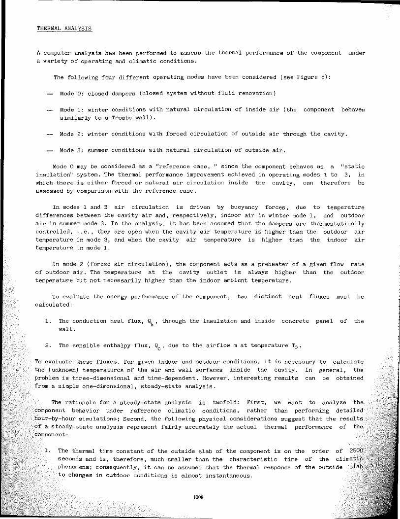
As a first step of the study, the thermal and hygrometric behavior of the component has been analYzed in the operating mode O. The results of the calculations are summarized in Figure 6. in which the temperature and water vapor pressure profiles across the component are shown. It is worth observing that under typical northern Italian winter conditions (i.e., ambient temperature of _5°C at 80% relative humidity) condensation may take place within the air cavity or the external slab; the condensed water, can however, be easily eliminated by ventilation, provided that a sufficient airflow takes place when the dampers are open.
The minimum volumetric flow rate of external air Gmin necessary to remove the condensed water can be estimated from a simple mass balance equation, i.e.:
mv water vapor mass flow rate per unit of wall surface area H = distance between air inlet and outlet openings (m) L = wall length (m) 3 Q = air density (kg!m )
2 (g!h-m )
(l)
x moisture content of air at saturation, at the temperature of the inside surface of the outside concrete panel (g vapor/kg air)
xe = moisture content of outdoor air (g vapor/kg air)
Assuming the outdoor conditions specified in Figure 6 (temperature _5°C, relative humidity = 80%) and for H = 2.7 m and L = 2.4 m, Equation 1 yields a value of the minimum airflow rate of 0.83 m
3/h, corresponding to an average air velocity inside the cavity of 0.001 m/s.
The airflow rate achieved by natural ventilation can be estimated, as approximation, with the equation
a first
G = 50 A (6T H)0.6 (2)
~ G = volumetric airflow rate (m3 /h) A, ~,cross area of the ventilation openings per unit length of the component (m2/m) ~ = 'temperature difference between cavity air and ambient air (oC).
Assuming A '= ,.0125 m2/m and ~T = 2°C, the airflow an average air velocity of about 0.002 mis, which velocity given by Equation 1.
1007
3 rate is equal to 1.72 m /h, is approximately two times
corresponding the minimum
to air
THERMAL ANALYSIS
A computer analysis has been performed to assess the thermal performance of the component under a variety of operating and climatic conditions.
The following four different operating modes have been considered (see Figure 5):
Mode 0: closed dampers (closed system without fluid renovation)
Mode 1: winter conditions with natural circulation of inside air (the component behaves similarly to a Trombe wall).
Mode 2: winter conditions wlth forced circulation of outside air through the cavity.
Mode 3: summer conditions with natural circulation of outside air.
Mode 0 may be considered as a "reference case, II since the component behaves as a "static insulation'! system. The thermal performance improvement achieved in operating modes 1 to 3, in which there is either forced or natural air circulation inside the cavity, can therefore be assessed by comparison with the reference case.
In modes 1 and 3 air circulation is driven by buoyancy forces, due to temperature differences between the cavity air and, respectively, indoor air in winter mode 1, and outdoor air in summer mode 3. In the analysis, it has been assumed that the dampers are thermostatically controlled, i.e., they are open when the cavity air temperature is higher than the outdoor air temperature in mode 3, and when the cavity air temperature is higher than the indoor air temperature in mode 1.
In mode 2 (forced air circulation), the component acts as a preheater of of outdoor air. The temperature at the cavity outlet is always higher temperature but not necessarily higher than the indoor ambient temperature.
a given flow rate than the outdoor
To evaluate the energy performance of the component, two distinct heat fluxes must be calculated:
1. The conduction heat flux, Qk' through the insulation and inside concrete panel of the wall.
2. The sensible enthalpy flux, Qc' due to the airflow m at temperature To.
To evaluate these fluxes. for given indoor and outdoor conditions, it is necessary the (unknown) temperatures of the air and wall surfaces inside the cavity. In problem is three-dimensional and time···dependent. However, interesting results can from a simple one-dimensional, steady-state analysis.
to calculate general, the
be obtained
The rationale for a steady-state analysis is twofold: First, we want to analyze the component behavior under reference climatic conditions, rather than performing detailed hour-by-hour simulations; Second. the following physical considerations suggest that the results of a steady-state analysis represent fairly accurately the actual thermal performance of the component:
1. The thermal time constant of the outside slab of the component is on the order of 2500 seconds and is, therefore, much smaller than the characteristic time of the climatic phenomena: consequently, it can be assumed that the thermal response of the outside slab to changes in outdoor conditions is almost instantaneous.
1008

2. The response of the air inside the cavity, both in terms of temperature variations and
fluid flow, is also virtually instantaneous; since the internal slab of the component is thermally isolated, these phenomena are influenced primarily by the dynamics of the external slab, which, as discussed above, is almost instantaneous.
Under the above hypotheses, the thermal analysis is carried out by solving a set of algebraic equations, each of them representing the energy balance of the external slab, air, and internal slab. (The equations are given in the Appendix.)
linear cavity
The outdoor conditions are described by a single parameter, i.e., by the sol-air temperature, which takes into account the combined effects of ambient temperature, radiation, and wind speed on the convective and radiative heat transfer at the outside
solar wall
surface. The sol-air temperature is calculated assuming for the solar absorptance the value a =
0.7; the surface conductance is c_alculated using the equations given by the ASHRAE Handbook of Fundamentals (ASHRAE 1985). The indoor conditions are assumed constant.
RESULTS OF THE THERMAL ANALYSIS
The following cases have been examined:
1. Winter conditions (modes 0, 1, and 2):
Outdoor temperature, Te = -10; -5; 0; 5; 10; 15°C Solar radiation, It = OJ 300; 500j 700 W/m2 Wind velocity, V = 0; 2; 4 mls
2. SUmmer conditions (modes 0 and 3):
Outdoor temperature, Te = 25; 30j 35°C Solar radiation, It = 500; 700 W/m2
Wind velocity, V = 0; 2; 4 mls
In all cases the ambient temperature is Ta 20 m3/h (mode 2).
20°C. The forced-ventilation airflow is equal to
By solving the energy balance of the component, the following quantities are determined (see Appendix):
1. The cavi ty air temperature, T:2..
2. The natural ventilation airflow rate, m.
3. The conductive heat flux, Qk'
4. The enthalpy flux, Qc' associated with the airflow m at temperature To'
5. The enthalpy flux, Qv' associated with the airflow m at temperature Te , where Te is the outdoor temperature.
A positive value of the heat fluxes Qk' Qc' and Qv implies a positive heat gain for the ambient (i.e., heat flows from outside to inside).
In modes 0 and 3, in which there is no air inflow into ambient, Qc is zero by Similarly. Qv is zero in modes 0, 1, and 3. Qv represents the ventilation heat load be present if the ventilation airflow m was introduced into ambient at the outdoor Te , rather than at the temperature To' which results from preheating the air into
1009
definition. that would temperature
the cavity:
the difference between Qv and Qc hence represents the reduction in ventilation heat load achieved by the component.
To quantify the component's thermal performance with a single parameter, the following ratio is introduced:
r
net total heat flux through the wall in the i-th operating mode (i heat flux through the wall in the reference case °
( 3)
1 ••• 3)
The results of the analysis are summarized in Tables 1 to 3. Each table shows a performance comparison between the reference case and one of the three operating modes. From of the results, some general conclusions can be drawn, which are summarized in paragraphs.
an inspection the following
Table 1 refers to the operating mode 1. In this case we have:
Q1 = Qk,l Qo = Qk,o
Air circulates only when the cavity air temperature is higher than room condition occurs when the net heat flow through the wall is positive ambient); the ratio r thus represents the increase of conductive heat respect to the reference case.
air temperature. (i .e., it flows gain of mode 1
This into with
It is important to observe that the component's performance depends very much on wind velocity. This is because the absorbed solar radiation -- which is the driving force of air motion -- is transferred partly to the cavity air by conduction, and partly is rejected to the outdoor ambient by convection and long-wave radiation. The ratio between the two fluxes depends on the ratio of the inside (conductive) and outside thermal resistances, the latter being very sensitive to wind velocity; for increasing wind velocities, the outside thermal resistance decreases and the fraction of the absorbed solar radiation exchanged with the outside ambient tends to unity.
Table 2 refers to the operating mode 2. In this case we have:
Three situations can take place:
1. If Q2< 0 and Qo< 0, there is a net heat loss through the component in both cases. It is always IQ21<IQ ol, and consequently -1 < r < O. The forced airflow always reduces the room thermal load; this is true even when It 0, for in this case the cavity air "recuperates" some of the heat lost through the inside slab. In this case, r represents the heat loss reduction.
2. If Q2> ° and Qo< 0, there is a net heat gain in operating mode 2, and a net heat loss in operating mode O. Consequently, r is always negative and less than -1.
3. If Q2> 0 and Qo> 0, there is a net heat gain in both operating modes. In this case, r is always positive and represents the heat gain increase.
Table 3 refers to the operating mode 3. In this case we have:
1010

It is always Q3 < Qo and 1Q31>0, IQol >0. In this case, reduction in heat gain achieved by natural ventilation. performance is particularly sensitive to wind velocity.
r is always < 0 and represents the In this case also, the component's
CONCLUSION
The computer analysis of the thermal performance of the component has shown that significant energy savings, as well as improved comfort conditions in unconditioned spaces, could be achieved in a proper climatic setting. In particular, the addition of dampers to control and promote airflow can replace the need of additional insulation, with beneficial effects also on summer comfort conditions. From a more general viewpoint, a component of similar design shows good promise of achieving satisfactory performances with respect to static behavior, moisture prpblems, fire resistance, and sound insulation. These observations seem to encourage a deeper investigation of the behavior of dynamic insulation systems, both by means of more sophisticated simtUation tools and through laboratory and field experimentation.
REJ[J>I!ENCES
G., and Johansson, B. 1983. "Dynamic insulation - A ,i,nsulation through which a gas or fluid flow." Swedish
theoretical analysis of thermal Council for Building Research,
>';~'~~~~d~!:~en~L::a::n:!glaiS, C. ; Klarsfeld, S. ; and Caltagirone, J .P. 1983. "Quelques aspects ". sur I' isola tien dynamique." Revue Generale de Thermique, Vol. XXII.
ASHRAE handbook -- 1985 fundamentals, Chapter 23. Atlanta: American Society of Refrigerating, and Air-Conditioning Engineers, Inc.
1985. "The ventilated facade." Proceedings of the International Copenhagen.
Matsson, M. 1981. 1!Provhus med dynamisk isolering." Rapport R 142. Swedish Building Research, Stockholm.
M.R. 1976. "Nouveaux procedes d'isolation thermique: de l'isolation statique a fi'at"c,n thermedynamique." Proceedings of the VII Journees d' etudes du Comi te Francais
Paris.
de realisation dtisolation dynamique. tr Cahiers du Centre
~~!!~~~tJ~~~~~~~~~~, n. 1541.
entifique et Technique du Batiment, Plan Construction, and Ecole Nationale des ponts es. 1983. Proceedings of the International Conference on Innovating Technologies
Paris, 8-10 Novembre 1983.
and Koshkin, N.N. 1960. "New cold store insulation system." Bulletin de Commission V. Marseille.
, and Arquis. E. 1983. IIEtudes d'un systeme d'isolation dynamique." Proceedings of du Fro' Commission B1, Paris.
S~ik~~i~ir:i~a!lturbanisme et du Logement.1981. "Programme Habitat Econome en Energie H2E85 ::;:' Hyperisole." Plan Construction I Paris.
lOll

APPENDIX - MATHEMATICAL MODEL
The mathematical model of the thermal behavior of the component is based on the hypotheses
of steady-state, one-dimensional heat transfer; the airflow in the cavity is also treated
as one-dimensional and steady-state.
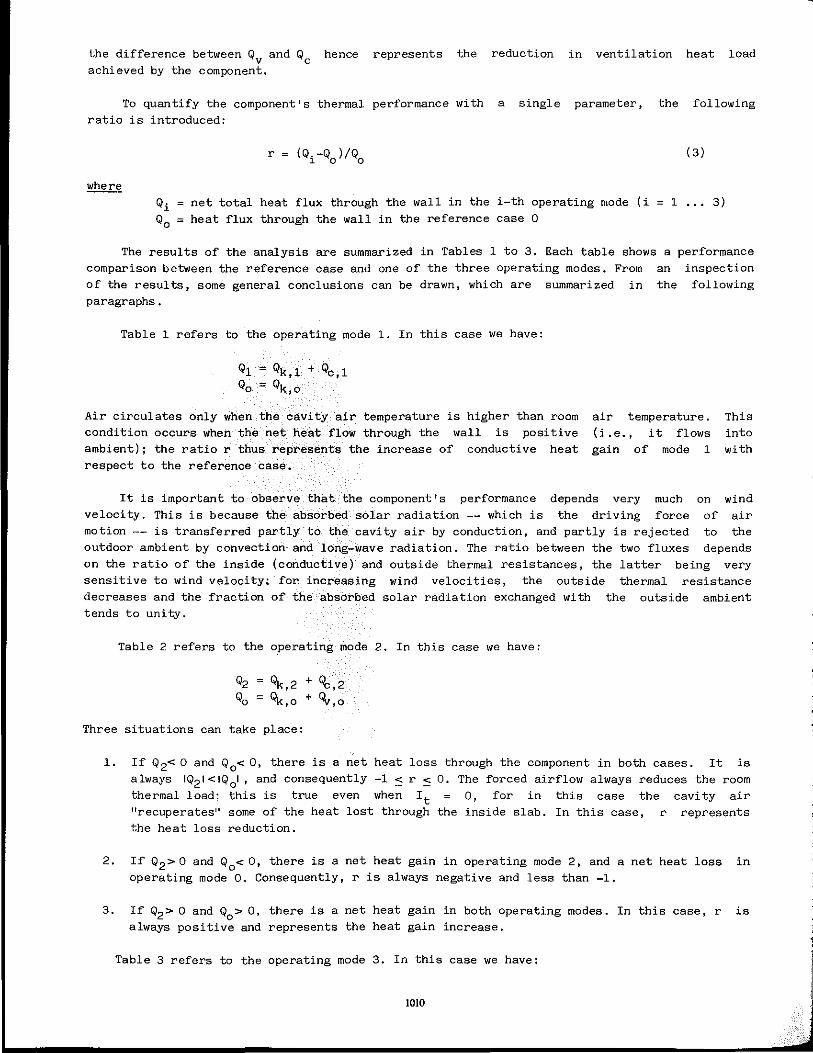
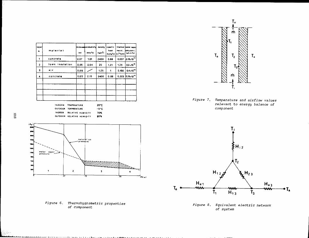
The temperature distribution in the component is determined by solving three energy balance equations (one for the external slab, one for the air cavity, and one for the internal slab -- see Figures 5, 7, and 8), which can be written, in matrix form, as:
where
The symbols
H12 H
23 H
13 H
e1 H a3
Hi2
T T
e a
T i
H 12
H23
H H13
He1 a3
H i2
T 0
where S
h e
ii a R Rse
.sa m e
hP
he _s T
[Al IT} = IE}
{''' + H12 + H - H - H 13 12 13
A - H H12 + H23 + Hi2 - H
12 23 - H - H H + H
.,] 13 23 13 23 a3
T ={T T2 T3 }T 1
B {H T H T H T } T e1 e i2 i a3 a '
in the above equations have the following meaning:
convective thermal conductance between surface 1 and air convective thermal conductance between surface 3 and air radiative thermal conductance between surfaces 1 and 3
overall thermal conductance between outdoor ambient and surface 1
overall thermal conductance between indoor ambient and surface 3 equivalent conductance which accounts for the enthalpy flux associated with airflow in the cavity outdoor ambient temperature indoor ambient temperature temperature of the air at the cavity inlet
h S he S
e _-3 4 a £ T [R + {R
se +
Ra 2 rIi e
-1 (l/h S) 1 (l/heS)1 -1
a (assuming T = (T +T. )/2)
tempe?ature 2 0'
of the air at the cavity outlet.
wall surface area convective heat transfer coefficient equivalent emittance of surfaces 1 and 3 Stefan-Boltzmann constant thermal resistance of outside slab thermal resistance of inside slab air mass flow rate specific heat of air at constant pressure outside surface heat transfer coefficient inside surface heat transfer coefficient (T
1+T
3)/2
The temperature T. is the air temperature at the cavity inlet; therefore: , 1012

Mode 0: H m 0 Mode 1 :
i2 T, T
1 a Mode 2: T, T
1 e Mode 3: T, T
1 e
The airflow rate m, in the case of natural convection (modes 1 and 3), can be calculated by modeling the cavity as a chimney. Assuming the standard hypotheses, the typical chimney flow equations yield:
where Q
A
H p.
m -,-2_G_H-,- [TT 21 _ 1] (I+P' )
air density at the temperature T2 area of the cavity cross section cavity height (height between inlet and outlet sections) flow friction coefficient (including distributed and concentrated losses)
TABLE 1
Simulation Results Comparison of Operating Modes o and 1
V 0
Te -10 -5 0 5 10 15
It 0
300 1.17 1.79 2.08 2.28 500 1.85 2.09 2.26 2.41 2.53 2.64 700 2.43 2.53 2.62 2.71 2.79 2.86
V 2
Te -10 -5 0 5 10 15
It 0
300 1.40 2.02
500 0.50 1.84 2.24 2.50 700 1.69 2.14 2.42 2.62 2.78
V 4
Te -10 -5 0 5 10 15
It 0
300 1.70
500 1.81 2.28 700 1.88 2.32 2.60
V wind vel oc i ty (m/s)
It = solar radiation (W/m2)
T outdoor temperature ('C) e
1013

TABLE 2 Simulation Results
Comparison of Operating Modes o and 2
V 0
T -10 -5 0 5 10 15 e
It = 0 -0.08 -0.08 -0.07 -0.07 -0.07 -0.06
300 -0.50 -0.62 -0.82 -1.21 -2.50 17.36
500 -1.06 -1.37 -1.96 -3.65 -45.05 4.04
700 -1.92 -2.70 -4.71 -2.27 7.45 3.09
V 2
T -10 -5 0 5 10 15 e
It = 0 -0.07 -0.07 -0.06 -0.06 -0.06 -0.05
300 -0.28 -0.30 -0.34 -0.55 -0.96 -3.64
500 -0.48 -0.61 -0.81 -1.21 -2.51 20.94
700 -0.79 -1.01 -1.39 -2.31 -7.39 5.63
V = 4
T e -10 -5 0 5 10 15
It = 0 -0.06 -0.06 -0.06 -0.06 -0.06 -0.05
300 -0.23 -0.25 -0.28 -0.32 -0.57 -1.64
500 -0.31 -0.32 -0.48 -0.71 -1.29 -7.01
700 -0.47 -0.60 -0.81 -1.22 -2.52 22.83
V wind velocity (m/s) 2
It = solar radiation (W/m )
T outdoor temperature (·C) e
1014

TABLE 3 Simulation Results
Comparison of Operating Modes o and 3
V = 0
T = 25 30 35 e
It = 500 -0.30 -0.25 -0.21
700 -0.33 -0.28 -0.25
V = 2
To 25 30 35
It 500 -0.22 -0.17 -0.14
700 -0.25 -0.20 -0.17
V = 4
T 25 e 30 35
It 500 -0.17 -0.13 -0.10
700 -0.21 -0.16 -0.13
V wind vel oc i ty (m/s)
It solar radiation (W/m2)
T outdoor temperature ('C) e
1015

::; 0;
,.·C
-20·C
O'C ... ~o·c
'--
Figur~ 1. Temperature distribution in a cavity-filled wall with outside air flowing inward (left) and inside air flowing outward (right) for winter conditions
n 2O'C~ w'e
,'c ~"c
-tb
Figure 2. Temperature distribution in a permeable wall with outside air flowing in·ward (left) and inside air flowing outward (right) for winter conditions
• L I _'-'....' .• '" ............... ...1 ........<-~~.~ _____ ~~ ~ __ ,
1 2 3
JD 0 JjO
[j 4 05
J[~j 6
oj Ii I QI 8 0' -----. supply air
----+ exluust air C8J Ileal ,ecupe'alor
II buHd,"g cC:J:o COmponent
heal pump
Figure 3. Applications of dynamic insulation systems

o ::;
concrete panel
./ ./
-
-
/"
......
'-./ ././
/"~ concrete be.rinQ slab
insulatin • nel
air CI\li t
dlmDers
-~
d. m De rs
Figure 4. Cross section of building component
1r -[L: K ~ll-~ I ,
I
--11 ] L~ :11 -IL t I i Ii t I
Figure 5. Operating modes of building component: no air circulation (top left); natural circulation, winter (top right); forced circulation, winter (bottom left); natural circulation, summer (bottom right)
IIYI' hick .... Fnducti '; dlnlity 5pldlic th...",1 I-~''''JIO'
::; ;;
,. mite ril' h"t ..... t. Iml IWln,'CI I ..... ml )
IkJlk~"CI I",he/W)
1 concrete 0.07 1.91 2400 0.88 0.037
2 101m i n5ylation 0.05 0.04 20 1.21 1.25
3 • i r
• concrete
INOOO'
OUTDOOR
INOOOII:
OUTDOOR
.......... -.....
"",!I •• 'po. ,.., p.euy,. :--- ~L
Figure 6,
0.08 /' 1.25 1 0.156
0,05 2.15 2400 0.88 0.023
TEMHlATUItE 20'C TEM I"IIATUIE -SoC
RElATIVE HUMIDITY 70% RelATIVE HUMIDITY ,0%
Thermohygrometric properties of component
1,., CD .... O.~O __ •• _Lo ____ ----'-o ~_ .... "L_'-.
11t".;One • 11Ii. m Pol
-, O.HMO
0.2.10"'"
6.4.10-4
0,19.10....(
•
Te
Figure 7.
He1
To t-m
T,
T. ~ T, 10..~ T.
m --t
T,
Temperature and airflow values relevant to energy balance of component
Ti
Hi 2
T2
. ............ .. "Of.. ......... ..... T Hn .. T .... v. °T Ha3
Figure 8.
1 13 3 •
Equivalent electric network of system