Embed Size (px)
Citation preview

Performance of a LiBr water absorption chilleroperating with plate heat exchangers
M. de Vega a,*, J.A. Almendros-Ibanez a, G. Ruiz b
a Departamento de Ingenierıa Termica y de Fluidos, Universidad Carlos III de Madrid, Avda. Universidad 30,
28911 Leganes, Madrid, Spainb Now at: Unidad de Eficiencia Energetica, Departamento de I + D, Besel S.A., Avda. Mediterraneo 22, 28912 Leganes, Madrid, Spain
Abstract
This paper studies the performance of a lithium bromide water absorption chiller operating with plate heat exchangers(PHE). The overall heat transfer coefficients in the desorber, the condenser and the solution heat recoverer are calculatedusing the correlations provided in the literature for evaporation, condensation and liquid to liquid heat transfer in PHEs.The variable parameters are the external driving temperatures. In the desorber, the inlet temperature of the hot fluid rangesfrom 75 �C to 105 �C. In the condenser and the absorber, the inlet temperature of the cooling water goes from 20 �C to40 �C. The coefficient of performance (COP) obtained ranges from 0.5 to 0.8 for cooling duties ranging from 2 kW to12 kW. The chiller response to different hot fluid temperatures and circulated mass flow rates is also presented. The performance and the internal parameters of the chiller at part load are, therefore, calculated. A higher efficiency results whenthe solution pumped from the absorber to the desorber decreases. The heat transfer analysis of the PHEs is also presented.The overall heat transfer coefficient in the desorber, equal to 790 W/m2 K at the design conditions, is also analysed at partload. The condenser performance can be represented by a similar relationship found in conventional air cooled condensers.
Keywords: LiBr water absorption; Plate heat exchanger
1. Introduction
Absorption chillers using the LiBr water mixture have become one of the well accepted choices to over-come the environmental problems associated with the use of traditional refrigerants: CFCs and HCFCs. Con-sequently, large capacity direct fired and waste heat driven cooling systems have been studied andcommercialised. Besides, it is difficult to extend their use to small sized air conditioning systems. This possi-bility seems to be promising since the temperature required in the heating source to power the desorber of theLiBr H2O solution (less than 120 �C) may be provided by solar energy systems with low cost solar collectors
* Corresponding author. Tel.: +34 91 6249913; fax: +34 91 6249430.E mail address: [email protected] (M. de Vega).
1
Nomenclature
A heat transfer area (m2)Bo boiling numberCOP coefficient of performancecP specific heat (kJ/kg K)Dh hydraulic diameter (m)Eff efficiencyh specific enthalpy (kJ/kg)m mass flow rate (kg/h)G mass flux (kg/m2 s)Nu Nusselt numberP pressure (Pa)Pr Prandlt numberQ heat transfer rate (kW)R fouling resistance (m2 K/W)Re Reynolds numbert temperature (�C)U global heat transfer coefficient (W/m2 K)w specific work (kJ/kg)x solution concentration
Greek symbols
a heat transfer coefficient (W/m2 K)g pump efficiencyl viscosity of liquid phase (N/m s2)q density (kg/m3)Dt log mean temperature difference (�C)
Subscripts
in
[1 3]. One of the main constraints for the development of these small air conditioning units is the size required,which is still, by far, larger than the size of the conventional mechanical compression systems. To this effect,the use of compact heat exchangers in absorption systems needs to be investigated.
2

In order to increase the cooling capacity to volume ratio in absorption systems, we are working on a LiBrH2O absorption chiller prototype employing plate heat exchangers in the desorber, the condenser and thesolution heat recoverer. We are primarily interested in the analysis of the thermal and thermodynamic theo-retical performance of this single effect chiller. The results are presented here.
Plate heat exchangers (PHE) are frequently employed in the food and chemical industry and are primarilyused in liquid to liquid heat exchange duties. Thus, performance in single phase applications is extensively doc-umented [4 6]. Recently, new theoretical and experimental efforts have been developed for the use of PHEs inevaporation and condensation processes [7 10]. Nevertheless, only a little information is available describingthe operation of absorption chillers with PHEs [11,12].
Many works referring to ideal thermodynamic simulations of absorption cycles are available in the litera-ture [13 16]. In most of these works, sensitivity analysis is done on the basis of the internal operating condi-tions: condensing temperature and final absorption and desorption temperatures. This is mainly due to thefact that the heat transfer equations are not considered in the simulations. Instead, we propose to predictthe operational characteristics as a function of the external driving conditions: inlet temperatures of the cool-ing water and the hot fluid, respectively, entering the condenser and the desorber. In the present paper, inorder to study the performance of the single effect LiBr H2O absorption machine, the thermodynamic absorp-tion cycle is coupled with the heat transfer characteristics of the selected plate heat exchangers. The resultsobtained will be used as a predictive tool for the performance of the system over a complete set of externalconditions, as will correspond to a complete operation during a whole season. This whole season operationwill provide a more realistic seasonal coefficient of performance that could be used to compare the perfor-mance of absorption chillers with PHEs with other types of machines. This will be, in the near future, verifiedwith the results obtained in the experimental device, which is under construction.
2. Description of the system
The single effect absorption system consists of the following components: absorber, desorber, vapour sep-arator, condenser, evaporator, heat recoverer, expansion and throttle valves and solution pump. The system isschematically shown in Fig. 1.
The distinguishing feature of the present system is that it incorporates plate heat exchangers: the desorber(fed by a liquid heat source); the condenser and the heat recoverer employed to preheat the solution on its wayto the desorber. In the desorber, the external hot fluid (for example, pressurised hot water, heated by concen-trators or vacuum tube solar collectors) provides the heat to boil the solution. Superheated refrigerant vapour,which separates from the solution, is generated. Traditionally, the desorber and the condenser are containedin the same vessel. According to the configuration of our experiment, two separate heat exchangers are
DESORBER CONDENSER
CWo
CWi
Hfi
HfO
CWo
CWi
chO
chI
HEAT
RECOVERER
VAPOUR
SEPARATOR
1
2
34
ABSORBER EVAPORATOR
5
6
7 8
9
10
Fig. 1. Schematic diagram of the absorption chiller configuration.
3

7
DESORBER CONDENSER
CWo
CWi
Hfi
HfO
VAPOUR
SEPARATOR
1
2
T
T
T T T
TT
T 8
T
Sight glass
Thermocouple
Flowmeter
Fig. 2. Schematic diagram of the experimental set up.
considered, and a vapour separator is placed at the exit of the desorber. The leaving vapour stream is sent tothe condenser (1) and the concentrated solution (8) is driven back to the absorber through the heat recoverer(9) and the throttling valve (10). The absorber is the component in the solution cycle that sucks the vapour atlow pressure and low temperature (4) that condenses in the solution. The cooling water temperature deter-mines the equilibrium exit condition of the solution (5), which is pumped (6) and preheated (7) before enteringthe desorber. The superheated vapour (1) condenses (2) at a rate and at a temperature that depend on both thevapour mass flow rate and the inlet temperature of the cooling water. The evaporation of the refrigerant (4)provides the cooling effect used to chill a given water flow rate (ch).
The LiBr H2O chiller works by evaporating the refrigerant at temperatures ranging from 2 �C to 12 �C andproviding a design cooling load of 7.5 kW. The plate heat exchangers considered in the study are commerciallyavailable PHEs. The plate surfaces are grooved with a corrugated sinusoidal shape and 60 � chevron angle.The plate separation has been taken equal to 3 mm. The desorber, a 10-plate, 10 kW, one pass, counter currentflow heat exchanger, is designed to provide a vapour stream of 11 kg/h. This mass flow rate of refrigerant con-denses at a design temperature of 40 �C in an 8 kW condenser. The condenser is also configured as a one pass,counter current flow heat exchanger. Typically in PHEs, according to Ref. [17], the fouling factors are in theorder of 0.1 m2 K/kW. This is the value selected for the present calculation.
An experimental device with these specifications is being constructed and partially operated, including thedesorber, the vapour separator and the condenser, as shown in Fig. 2.
3. Heat transfer and cycle simulation
As previously stated, in the present study, the properties of the working fluids are determined simulta-neously with solving the thermodynamic cycle and the heat transfer equations in the plate heat exchangers.
In single phase, liquid to liquid plate heat exchangers, according to Ref. [4], there is still a lack of general-ised thermal hydraulic predictive tools. Nevertheless, a general correlation for the Nusselt number of the kind,
Nu ¼ C1ReaPr1=3 ð1Þ
is employed. The values of C1 and a depend on the geometry of the plates [8]. For chevron plates at 60�,C1 0.2 and a 0.7 as in Refs. [9,10]. These are the selected values to evaluate all the single phase heat trans-fer coefficients (both sides of the heat recoverer and external fluids in both the desorber and the condenser).Some experimental works on condensation and evaporation in plate heat exchangers are available in theliterature [7 10].
In the condenser, the Nusselt number for condensation is calculated using the correlation suggested in Ref.[8]:
Nu ¼ C2RebeqPr1=3 ð2Þ
where Reeq is the equivalent Reynolds number defined as
Reeq ¼GeqDh
lð3Þ
4
Here, Geq is an equivalent mass flux as defined in Refs. [8 10]. The coefficients are C2 3.2 and b 0.4 as inRef. [8].
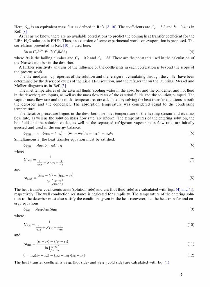
As far as we know, there are no available correlations to predict the boiling heat transfer coefficient for theLiBr H2O solution in PHEs. Thus, an extension of some experimental works on evaporation is proposed. Thecorrelation presented in Ref. [10] is used here:
Nu ¼ C3Re0:7Pr1=3ðC4Bo0:5Þ ð4Þ
where Bo is the boiling number and C3 0.2 and C4 88. These are the constants used in the calculation ofthe Nusselt number in the desorber.A further sensitivity analysis of the influence of the coefficients in each correlation is beyond the scope ofthe present work.
The thermodynamic properties of the solution and the refrigerant circulating through the chiller have beendetermined by the described cycles of the LiBr H2O solution, and the refrigerant on the Duhring, Merkel andMollier diagrams as in Ref. [3].
The inlet temperatures of the external fluids (cooling water in the absorber and the condenser and hot fluidin the desorber) are inputs, as well as the mass flow rates of the external fluids and the solution pumped. Thevapour mass flow rate and the outlet temperatures are calculated by solving the heat transfer equations in boththe desorber and the condenser. The absorption temperature was considered equal to the condensingtemperature.
The iterative procedure begins in the desorber. The inlet temperature of the heating stream and its massflow rate, as well as the solution mass flow rate, are known. The temperatures of the entering solution, thehot fluid and the solution outlet, as well as the separated refrigerant vapour mass flow rate, are initiallyguessed and used in the energy balance:
QDES ¼ mHfðhHfi � hHfoÞ ¼ ðmd � mRÞh8 þ mRh1 � mdh7 ð5Þ
Simultaneously, the heat transfer equation must be satisfied:QDES ¼ ADESUDESDtDES ð6Þ
whereUDES ¼1
1aDESþ RDES þ 1
aHf
ð7Þ
and
DtDES ¼ðtHfi � t8Þ � ðtHfo � t7Þ
ln tHfi�t8tHfo�t7
� � ð8Þ
The heat transfer coefficients aDES (solution side) and aHf (hot fluid side) are calculated with Eqs. (4) and (1),respectively. The wall conduction resistance is neglected for simplicity. The temperature of the entering solu-tion to the desorber must also satisfy the conditions given in the heat recoverer, i.e. the heat transfer and en-ergy equations:
QRH ¼ ARHU RHDtRH ð9Þ
whereURH ¼1
1aRHhþ RRH þ 1
aRHc
ð10Þ
and
DtRH ¼ðt8 � t7Þ � ðt10 � t5Þ
ln t8�t7
t10�t5
� � ð11Þ
0 ¼ mdðh7 � h6Þ � ðmd � mRÞðh8 � h9Þ ð12Þ
The heat transfer coefficients aRHh (hot side) and aRHc (cold side) are calculated with Eq. (1).
5
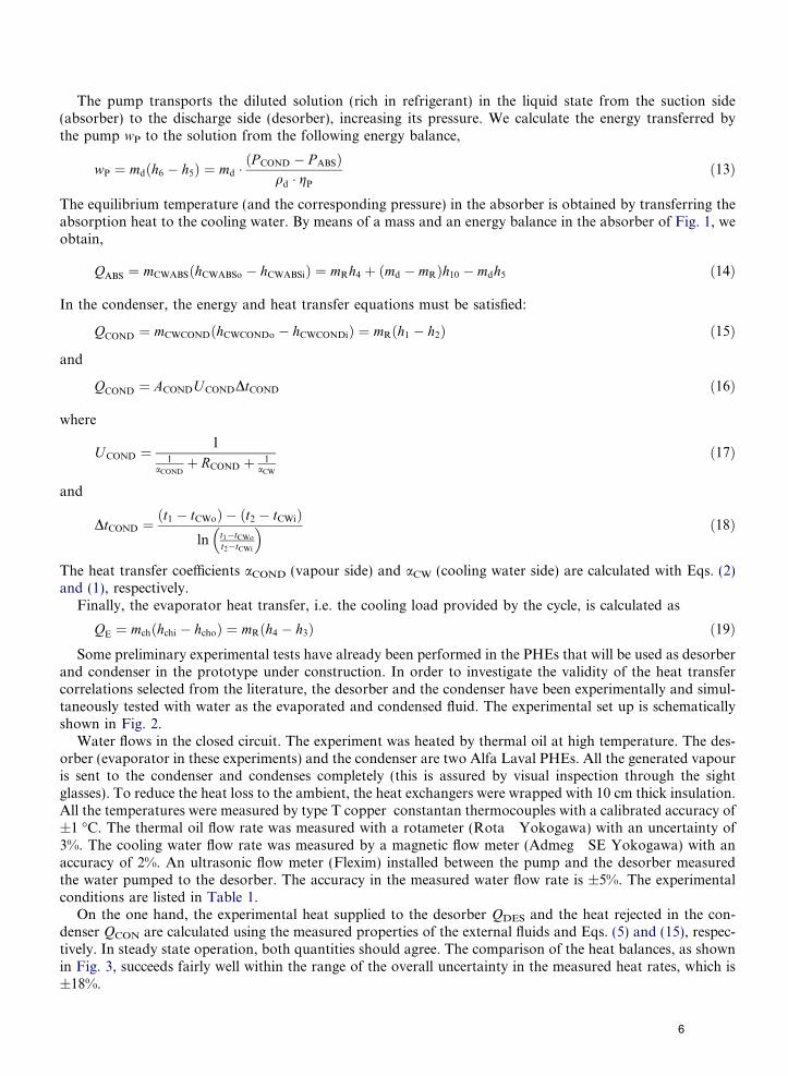
The pump transports the diluted solution (rich in refrigerant) in the liquid state from the suction side(absorber) to the discharge side (desorber), increasing its pressure. We calculate the energy transferred bythe pump wP to the solution from the following energy balance,
wP ¼ mdðh6 � h5Þ ¼ md �ðP COND � P ABSÞ
qd � gP
ð13Þ
The equilibrium temperature (and the corresponding pressure) in the absorber is obtained by transferring theabsorption heat to the cooling water. By means of a mass and an energy balance in the absorber of Fig. 1, weobtain,
QABS ¼ mCWABSðhCWABSo � hCWABSiÞ ¼ mRh4 þ ðmd � mRÞh10 � mdh5 ð14Þ
In the condenser, the energy and heat transfer equations must be satisfied:
QCOND ¼ mCWCONDðhCWCONDo � hCWCONDiÞ ¼ mRðh1 � h2Þ ð15Þ
and
QCOND ¼ ACONDUCONDDtCOND ð16Þ
where
U COND ¼1
1aCOND
þ RCOND þ 1aCW
ð17Þ
and
DtCOND ¼ðt1 � tCWoÞ � ðt2 � tCWiÞ
ln t1�tCWo
t2�tCWi
� � ð18Þ
The heat transfer coefficients aCOND (vapour side) and aCW (cooling water side) are calculated with Eqs. (2)and (1), respectively.
Finally, the evaporator heat transfer, i.e. the cooling load provided by the cycle, is calculated as
QE ¼ mchðhchi � hchoÞ ¼ mRðh4 � h3Þ ð19Þ
Some preliminary experimental tests have already been performed in the PHEs that will be used as desorberand condenser in the prototype under construction. In order to investigate the validity of the heat transfercorrelations selected from the literature, the desorber and the condenser have been experimentally and simul-taneously tested with water as the evaporated and condensed fluid. The experimental set up is schematicallyshown in Fig. 2.
Water flows in the closed circuit. The experiment was heated by thermal oil at high temperature. The des-orber (evaporator in these experiments) and the condenser are two Alfa Laval PHEs. All the generated vapouris sent to the condenser and condenses completely (this is assured by visual inspection through the sightglasses). To reduce the heat loss to the ambient, the heat exchangers were wrapped with 10 cm thick insulation.All the temperatures were measured by type T copper constantan thermocouples with a calibrated accuracy of±1 �C. The thermal oil flow rate was measured with a rotameter (Rota Yokogawa) with an uncertainty of3%. The cooling water flow rate was measured by a magnetic flow meter (Admeg SE Yokogawa) with anaccuracy of 2%. An ultrasonic flow meter (Flexim) installed between the pump and the desorber measuredthe water pumped to the desorber. The accuracy in the measured water flow rate is ±5%. The experimentalconditions are listed in Table 1.
On the one hand, the experimental heat supplied to the desorber QDES and the heat rejected in the con-denser QCON are calculated using the measured properties of the external fluids and Eqs. (5) and (15), respec-tively. In steady state operation, both quantities should agree. The comparison of the heat balances, as shownin Fig. 3, succeeds fairly well within the range of the overall uncertainty in the measured heat rates, which is±18%.
6

Table 1Set of experimental parameters
Parameters Measurements
Heating fluid mass rate (kg/h) 3664 3669 3667 3869 2881 3640 3620Water cooling mass rate (kg/h) 1110 1502 1505 218 595 2290 2090Water pumped to the desorber (kg/h) 244 221 193 212 182 284 155Cooling water temperature (�C) 20.4 24.1 26 21.8 19 19.1 21.2Heating fluid temperature (�C) 112 103 107 102 114 105 114
W)
0
5
10
15
20
25
0 5 10 15 20 25
Measured condenser heat transfer (k
Mea
sure
d d
eso
rber
hea
t tr
ansf
er (
kW)
18% ±
Fig. 3. Desorber and condenser measured heat transfer rates.
On the other hand, using the measured mass flow rates and the temperatures of the external streams, tHfi
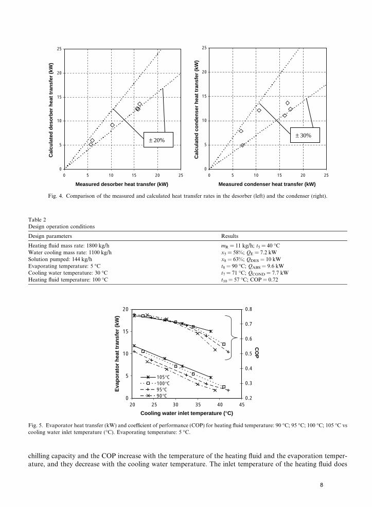
and tCWi, the heat transfer coefficients are calculated with Eqs. (1) (4). The heat transfer problem is solved,and the resultant heat transfer rates in the desorber, Eqs. (6) (8) and the condenser, Eqs. (16) (18), are com-pared to the measured values (Fig. 4). The results compare well. The condenser presents a higher dispersiondue to the uncertainty in the vapour mass flow rate, which is not directly measured.
The main interest in the present paper is to predict the performance of the absorption chiller operating withPHEs. These first results indicate that the heat transfer correlations selected seem correct for our purpose.
4. Results
The set of conditions for which Eqs. (1) (21) have been solved are the following: evaporation temperatureranging from 2 �C to 12 �C; inlet cooling water temperature ranging from 20 �C to 40 �C; heating fluid inlettemperature going from 75 �C to 115 �C (the lower value is limited by the condensing temperature, while theupper limit is imposed by the risk of crystallization). The first results correspond to a flow rate of 144 kg/h ofsolution pumped from the absorber. All the external flow rates are kept constant, equal to the design operatingconditions (Table 2).
4.1. Performance at constant solution flow rate
The cooling effect and the coefficient of performance for a given evaporation temperature and desorber inlettemperature are shown in Figs. 5 and 6, respectively. In both figures, the expected behaviour is confirmed: the
7
0
5
10
15
20
25
0 5 10 15 20 25
Measured desorber heat transfer (kW)
Cal
cula
ted
des
orb
er h
eat
tran
sfer
(kW
)
0
5
10
15
20
25
0 5 10 15 20 25
Measured condenser heat transfer (kW)
Cal
cula
ted
co
nd
ense
r h
eat
tran
sfer
(kW
)
± 20%± 30%
Fig. 4. Comparison of the measured and calculated heat transfer rates in the desorber (left) and the condenser (right).
Table 2Design operation conditions
Design parameters Results
Heating fluid mass rate: 1800 kg/h mR = 11 kg/h; t5 = 40 �CWater cooling mass rate: 1100 kg/h x5 = 58%; QE = 7.2 kWSolution pumped: 144 kg/h x8 = 63%; QDES = 10 kWEvaporating temperature: 5 �C t8 = 90 �C; QABS = 9.6 kWCooling water temperature: 30 �C t7 = 71 �C; QCOND = 7.7 kWHeating fluid temperature: 100 �C t10 = 57 �C; COP = 0.72
0
5
10
15
20
20 25 30 35 40 45
Cooling water inlet temperature (°C)
Eva
po
rato
r h
eat
tran
sfer
(kW
)
0.2
0.3
0.4
0.5
0.6
0.7
0.8
CO
P
105°C100°C95°C90°C
Fig. 5. Evaporator heat transfer (kW) and coefficient of performance (COP) for heating fluid temperature: 90 �C; 95 �C; 100 �C; 105 �C vscooling water inlet temperature (�C). Evaporating temperature: 5 �C.
chilling capacity and the COP increase with the temperature of the heating fluid and the evaporation temper-ature, and they decrease with the cooling water temperature. The inlet temperature of the heating fluid does
8

0
5
10
15
20
15 20 25 30 35 40
Cooling water inlet temperature (°C)
Eva
po
rato
r h
eat
tran
sfer
(kW
)
0.2
0.3
0.4
0.5
0.6
0.7
0.8
CO
Pte =2°C te =5°C
te =8°C te =12°C
Fig. 6. Evaporator heat transfer (kW) and coefficient of performance (COP) for evaporation temperature: 2 �C; 5 �C; 8 �C; 12 �C vscooling water inlet temperature (�C). Desorber inlet temperature: 105 �C.
not present a great influence on the COP (Fig. 5). In comparison, the evaporation temperature greatly affectsthe COP (Fig. 6).
A better understanding of the operation of the chiller may be seen in Fig. 7. The internal parameters of theabsorption cycle, such as the condensing temperature and the concentration of the solution are represented asa function of the inlet temperature of the heating fluid and the cooling water inlet temperature. The calculatedchilling load is also represented. The evaporating temperature is kept constant at 5 �C. This is, for example, acondition to have chilled water at around 13 �C for an air conditioning system.
As an example, for a given cooling load of 7 kW, the chiller may be operated with a heating source at 85 �Cwhen the water cooling temperature is 26 �C. These conditions result in a condenser temperature of 35 �C. It
0
10
20
30
40
50
60
70
70 75 80 85 90 95 100 105 110 115 120
Desorber inlet temperature (°C)
Eva
po
rato
r C
oo
ling
wat
erh
eat
tran
sfer
(kW
) t
emp
erat
ure
( °C
)
35
40
45
50
55
60
65
70
Deso
rber exit L
iBr
percen
tage ratio
(%)
tcond=45°C tcond=40°C tcond=35°C
Fig. 7. Cooling load (kW), condensing temperature (tcond = 35 �C; 40 �C and 45 �C) and desorber exit LiBr percentage ratio (%) vsdesorber inlet temperature (�C) and cooling water temperature (�C). Evaporating temperature: 5 �C.
9

0
5
10
15
20
25
30
35
40
45
50
20 25 30 35 40 45Cooling water inlet temperature (°C)
Co
nd
ense
r te
mp
erat
ure
(°C
)
0
5
10
15
20
25
30
Vap
ou
r mass flo
w (kg
/h)
105°C100°C95°C90°C
Fig. 8. Vapour mass flow (kg/h) and condenser temperature (�C) vs cooling water inlet temperature (�C) for heating fluid temperatures:90 �C; 95 �C; 100 �C; 105 �C. Evaporator temperature: 5 �C.
will also be possible to obtain the same refrigerating capacity by heating the desorber at 97 �C at a higher out-side temperature (32 �C). In this last case, the condenser temperature will also be higher (40 �C).
In the present case, the correlation used for the plate heat exchanger in the condenser side establishes therelationship between the saturation temperature and the cooling water temperature. Fig. 8 shows how theincrease in the temperature of the heating source is followed by an increase in the generated refrigerantvapour. This leads to an increase in the condenser pressure as a result of the higher quantity of refrigerantvapour in the condenser. Consequently, the condenser temperature increases.
In real operation, the outside temperature may increase. This increase will be followed by an increase in thecooling duty. The condensation temperature can only be kept constant by an increase in the temperature of
0
10
20
30
40
50
70 80 90 100 110
Desorber inlet temperature (°C)
Eva
po
rato
r
C
oo
ling
wat
er
h
eat
tran
sfer
(kW
)
t
emp
erat
ure
(°C
)
0
0.1
0.2
0.3
0.4
0.5
0.6
0.7
0.8
0.9
CO
P
te=12°C te=8°C te=5°C
te=12°C te=8°C te=5°C
Condensing temperature 40°C
Condensing temperature 35°C
Fig. 9. Evaporator heat transfer (kW) and COP vs desorber inlet temperature (�C) and cooling water temperature (�C). Condensationtemperatures: 35 �C and 40 �C; Evaporation temperatures: 5 �C; 8 �C and 12 �C.
10
the heating source (see Fig. 7). For example, for a given load of 8 kW with an outside temperature of 30 �C,while the desorber is fed at 100 �C, the condenser temperature is 40 �C. If the outside temperature reaches40 �C, without modifying the temperature of the heating source, the refrigeration capacity will fall to 3 kW(and the condensing temperature will be above 45 �C). As a consequence, to maintain the load, the heatingsource has to be at a higher temperature (at least 112 �C), to provide a load of 8 kW. In such a case, the con-denser temperature will be equal to 45 �C, and the limit of crystallization will be closer, as it is shown by theexit solution concentration (65%) in Fig. 7. In this figure, the encircled operated condition (condensing at45 �C and heating the desorber at 115 �C) results in a too high concentration at the desorber outlet.
The above example illustrates one way to control the operation of the chiller in an off design condition,varying the desorber inlet heating temperature.
All the external operating conditions and the resultant performance values (cooling load and COP) areshown in Fig. 9. The temperatures of the external fluids determine the condensing temperatures for all the
0
2.5
5
7.5
10
12.5
18 20.5 23 25.5 28 30.5 33 35.5 38
Water cooling temperature (°C)
Eva
po
rato
r h
eat
tran
sfer
(kW
)
25% 35% 50% 65% 85% 100%
tcond=35°Ctcond=37°C tcond=40°C
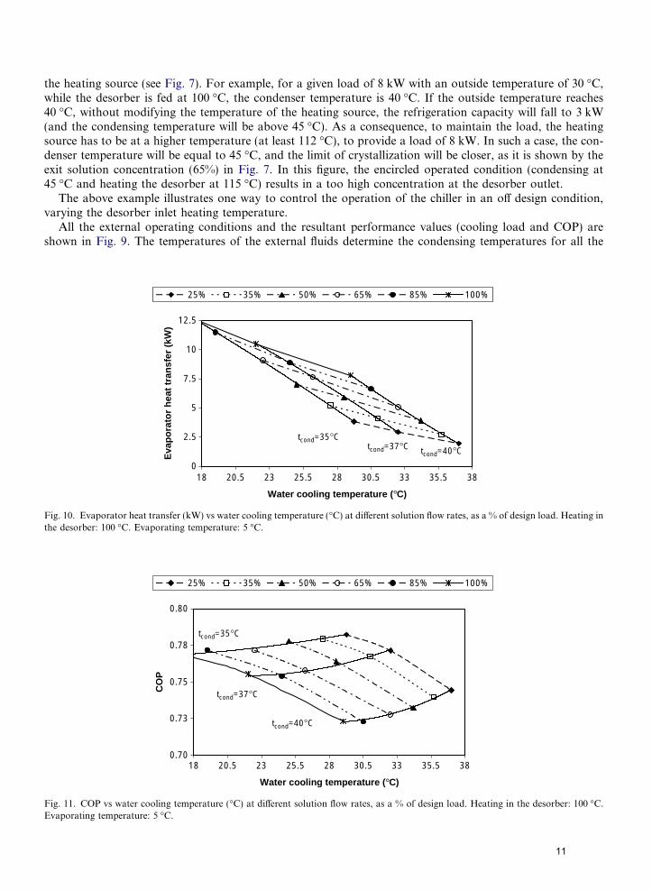
Fig. 10. Evaporator heat transfer (kW) vs water cooling temperature (�C) at different solution flow rates, as a % of design load. Heating inthe desorber: 100 �C. Evaporating temperature: 5 �C.
0.70
0.73
0.75
0.78
0.80
18 20.5 23 25.5 28 30.5 33 35.5 38
Water cooling temperature (°C)
CO
P
25% 35% 50% 65% 85% 100%
tcond=35°C
tcond=37°C
tcond=40°C
Fig. 11. COP vs water cooling temperature (�C) at different solution flow rates, as a % of design load. Heating in the desorber: 100 �C.Evaporating temperature: 5 �C.
11
possible evaporating conditions. In this way, for the present absorption chiller, it is possible to predict its com-plete performance.
4.2. Part load operation: solution flow rate control
One of the methods to reduce the refrigerating capacity of the absorption unit is to reduce the solution flowdelivered by the pump. A reduction in the generated vapour mass flow rate and, consequently, a decrease inthe cooling effect (Fig. 10) follow this reduction. Simultaneously, the condensing temperature decreases, as lessvapour enters the condenser, and therefore, a decrease in the condenser pressure follows.
According to Fig. 11, at part load, for a given mass flow rate of solution pumped, the COP increases as theoutside temperature decreases. This decrease is followed by a decrease in the condensing temperature.
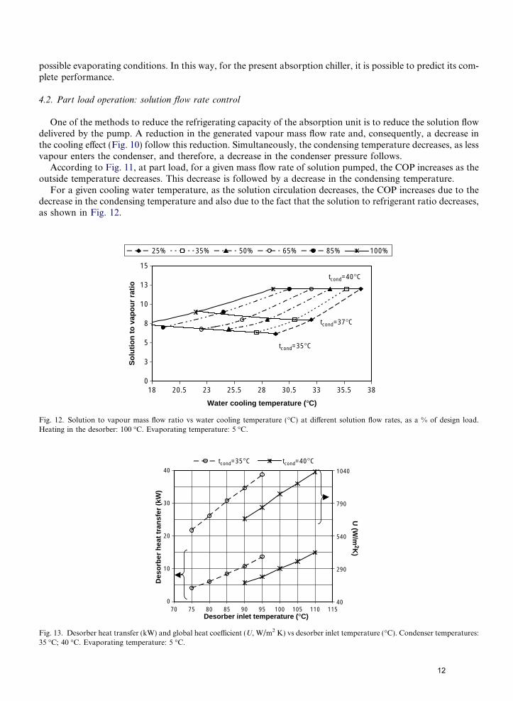
For a given cooling water temperature, as the solution circulation decreases, the COP increases due to thedecrease in the condensing temperature and also due to the fact that the solution to refrigerant ratio decreases,as shown in Fig. 12.
0
3
5
8
10
13
15
18 20.5 23 25.5 28 30.5 33 35.5 38
Water cooling temperature (°C)
So
luti
on
to
vap
ou
r ra
tio
25% 35% 50% 65% 85% 100%
tcond=35°C
tcond=37°C
tcond=40°C
Fig. 12. Solution to vapour mass flow ratio vs water cooling temperature (�C) at different solution flow rates, as a % of design load.Heating in the desorber: 100 �C. Evaporating temperature: 5 �C.
0
10
20
30
40
70 75 80 85 90 95 100 105 110 115Desorber inlet temperature (°C)
Des
orb
er h
eat
tran
sfer
(kW
)
40
290
540
790
1040
U (W
/m2K
)
tcond=35°C tcond=40°C
Fig. 13. Desorber heat transfer (kW) and global heat coefficient (U, W/m2 K) vs desorber inlet temperature (�C). Condenser temperatures:35 �C; 40 �C. Evaporating temperature: 5 �C.
12

4.3. Heat transfer
The analysis of the desorber plate heat exchanger is shown in Fig. 13. As the heating temperature increases,a higher wall superheat occurs. This gives a higher water vapour production (see the desorber outlet concen-tration in Fig. 7). In accordance with Refs. [7,10] the boiling heat transfer coefficient increases as a result of ahigher nucleation density on the plate and, therefore, a higher bubble generation frequency. The rise in theheat transfer is more pronounced as not only the heat transfer coefficient is higher but also the drivingtemperature.
The condenser performance is represented in Fig. 14. For a given water cooling inlet temperature, the heatrejected increases for higher condensing temperatures at an approximate rate of 0.73 kW/K. A higher heatingtemperature is also needed. The behaviour of the condenser can be represented by the following relationship:
Fig
Fig. 15conden
QCOND ¼ 0:73ðtCOND � tCWiÞ ð20Þ
The performance of the heat recoverer is shown in Fig. 15 as a function of the hot solution inlet temper-ature in the heat recoverer (t8 in Fig. 1). The heat recoverer efficiency is calculated as the ratio between the
0
2
4
6
8
10
12
14
29 31 33 35 37 39 41 43 45
Condensing temperature (°C)
Hea
t re
ject
ion
rat
e (k
W)
20°C 22°C 24°C 26°C 29°C 31°C 32°C
. 14. Performance of the PHE condenser (kW) vs condensing temperature (�C) at different water cooling inlet temperatures.
0
2
4
6
8
70 75 80 85 90 95 100
Hot solution inlet temperature (°C)
Hea
t re
cove
rer
hea
t tr
ansf
er (
kW)
0.55
0.575
0.6
0.625
Heat reco
verer efficiency
tcond=35°C tcond=40°C
. Heat recoverer performance (kW) and efficiency vs hot solution inlet temperature into the heat recoverer at 35 �C and 40 �Csing temperatures.
13
heat exchanged between the rich and the poor solution to the maximum heat that both currents couldexchange:
Eff ¼ QRH
QMAX
¼ ðmd � mRÞcPdðt8 � t10Þðmd � mRÞcPdðt8 � t6Þ
ð21Þ
The heat recoverer loses efficiency when working at higher temperature levels at a rate of 0.1%/K.
5. Conclusions
A LiBr water absorption system configured with plate heat exchangers in the desorber, the condenser andthe heat recoverer is considered. This system has the advantage of a higher chilling capacity to volume ratio.
The thermodynamic cycle has been solved simultaneously with the heat transfer equations of the selectedplate heat exchangers. The heat transfer correlations employed, taken from the literature, have already beenexperimentally validated in the desorber and the condenser with water as the evaporated and condensed fluid.
In this way, the operating conditions are defined according to the more realistic driving temperatures, i.e.the temperatures of the external fluids. Therefore, an arbitrary selection of the condensing and final desorptiontemperatures is avoided. The design and part load characteristics have been investigated for a complete set ofexternal temperatures. The result can be used as a performance predictive tool.
High COPs, as high as 0.8, have been found, but only for low ambient temperatures (around 20 �C). Athigher ambient temperatures (more than 30 �C), the COP approximates 0.75 but at the expense of higher heat-ing temperatures.
Off design operation has been analysed in two ways: controlling the heating source and controlling the cir-culated solution flow rate. In the first case, special care has to be taken to avoid crystallization. In the secondcase, at part load, when the circulating solution decreases, the decrease in the vapour flux is more pronounced,and the solution to refrigerant ratio decreases. As a consequence, the COP increases.
Acknowledgement
This work was partially funded by CICYT Ministerio de Ciencia y Tecnologıa (CLIMABCAR project no.DPI 2003-01567).
References
[1] Lamp P, Ziegler F. European research on solar assisted air conditioning. Int J Refrig 1998;21(2):89 99.[2] Filipe Mendes L, Collares Pereira M, Ziegler F. Supply of cooling and heating with solar assisted absorption heat pumps: an energetic
approach. Int J Refrig 1998;21(2):116 25.[3] Izquierdo M, de Vega M, Lecuona A, Rodrıguez P. Compressors driven by thermal solar energy: entropy generated, exergy destroyed
and exergetic efficiency. Sol Energy 2002;72(4):363 75.[4] Manglik RM. Plate heat exchangers for process industry applications: enhanced thermal hydraulic characteristics of chevron plates.
In: Manglik RM, Kraus AD, editors. Process enhanced and multiphase heat transfer. Begell House; 1996. p. 267 76.[5] Muley A, Manglik RM. Experimental study of turbulent flow heat transfer and pressure drop in a plate heat exchanger with chevron
plates. Trans ASME 1999;121:110 7.[6] Martin H. A theoretical approach to predict the performance of chevron type plate heat exchangers. Chem Eng Process
1996;35:301 10.[7] Watel B. Review of saturated flow boiling in small passages of compact heat exchangers. Int J Therm Sci 2003;42:107 40.[8] Wurfel R, Ostrowski N. Experimental investigations of heat transfer and pressure drop during the condensation process within plate
heat exchangers of the herringbone type. Int J Therm Sci 2004;43:59 68.[9] Yan Y Y, Lio H C, Lin T F. Condensation heat transfer and pressure drop of refrigerant R 134a in a plate heat exchanger. Int J Heat
Mass Trans 1999;42:993 1006.[10] Hsieh YY, Lin TF. Saturated flow boiling heat transfer and pressure drop of refrigerant R 410A in a vertical plate heat exchanger. Int
J Heat Mass Trans 2002;45:1033 44.[11] Flamensbeck M, Summerer F, Riesch P, Ziegler F, Alefeld G. A cost effective absorption chiller with plate heat exchangers using
water and hydroxides. Appl Therm Eng 1998;18(6):413 25.[12] Valles M, Bourouis M, Boer D, Coronas A. Absorption of organic fluid mixtures in plate heat exchangers. Int J Therm Sci
2003;42:85 94.
14

[13] Herold KE, Radermacher R, Klein SA. Absorption chillers and heat pumps. CRC Press, Inc; 1996.[14] Romero RJ, Rivera W, Gracia J, Best R. Theoretical comparison of performance of an absorption heat pump system for cooling and
heating operating with an aqueous ternary hydroxide and water/lithium bromide. Appl Therm Eng 2001;21:1137 47.[15] Saravanan R, Maiya MP. Effect of component pressure drops in two fluid pumpless continuous vapour absorption refrigerator. Energ
Convers Manage 1997;38(18):1823 32.[16] Florides GA, Kalogirou SA, Tassou SA, Wrobel LC. Design and construction of a LiBr water absorption machine. Energ Convers
Manage 2003;44:2483 508.[17] Hesselgreaves JE. An approach to fouling allowances in the design of compact heat exchangers. Appl Therm Eng 2002;22:755 62.
15


![Energy Conversion and Management - solarpaces.org · LiBr absorption chiller [34,35]: evacuated tube collectors with selective surface exhibit efficiency higher than 65% for a fluid](https://img.dokumen.tips/doc/110x75/5d586eb388c99373028bd3a8/energy-conversion-and-management-libr-absorption-chiller-3435-evacuated.jpg)