Embed Size (px)
Citation preview

PERFORMANCE EVALUATION TEST REPORT
Rendered to:
CBT SUPPLY, INC. / D.B.A. SMARTDESKS
PRODUCT: FFIT Floor
TYPE: Fixed Height Low Profile Raised Floor System Component
Report No: A9300.03-106-31
Report Date: 05/25/12
Test Record Retention Period: 09/13/15
Architectural Testing
130 Derry Court York, PA 17406-8405 phone: 717-764-7700 fax: 717-764-4129 www.archtest.com

PERFORMANCE EVALUATION TEST REPORT
Rendered to:
CBT SUPPLY, INC. / D.B.A. SMARTDESKS
83 Jacobs Road
Rockaway, New Jersey 07866
Report No: A9300.03-106-31
Test Dates: 11/16/10
Through: 09/13/11
Report Date: 05/25/12
Test Record Retention Period: 09/13/15
Product: FFIT Floor
Type: Fixed Height Low Profile Raised Floor System Component
Project Summary: Architectural Testing, Inc. was contracted by Powerflor USA, Inc. to
perform performance evaluations on the 2.75 inch raised floor system panel components of the
CBT Supply, Inc. / D.B.A. SMARTdesks FFIT system. This test report is a reissue of the
original report A9300.01-106-31. This report is issued in the name of CBT Supply, Inc. dba
SMARTdesks. This report details the procedures employed and results of this evaluation.
Test Method: The test specimens were evaluated in accordance with the following:
CISCA Recommended Test Procedures for Access Floors
Section 1 - Concentrated Load
Section 2 - Ultimate Loading
Section 3 - Rolling Loads (Wheel A, 10 Pass Test)
ASTM D 635-10, Standard Test Method for Rate of Burning and/or Extent and Time of
Burning of Plastics in a Horizontal Position.
ASTM D 1929-96 (Reapproved 2001)e1
, Standard Test Method for Determining Ignition
Temperatures of Plastics.
ASTM D 2843-99 (2004), Standard Test Method for Density of Smoke from the Burning or
Decomposition of Plastics.
ASTM E 2322-03 (Reapproved 2009), Standard Test Method for Conducting Transverse
and Concentrated Load Tests on Panels Used in Floor and Roof Construction.
Architectural Testing
130 Derry Court York, PA 17406-8405 phone: 717-764-7700 fax: 717-764-4129 www.archtest.com

A9300.03-106-31
Page 2 of 8
Test Procedures: Testing was performed on raised floor system panel components
representative of the CBT Supply, Inc. / D.B.A. SMARTdesks FFIT system. Test materials were
provided by Powerflor USA, Inc. on behalf of CBT Supply, Inc. / D.B.A. SMARTdesks and
sampled by a representative of Architectural Testing, Inc. on October 29, 2010 at the Powerflor
USA, Inc. Bel Air, Maryland facility unless otherwise stated in the individual test component
produces section.
The complete raised floor panel specimens (overall nominal dimensions: 19.75 in x 19.75 in.)
consisted of four quarter panels (individual panel section nominal dimensions: 9.75 in. x 9.75 in.
x 2.75 in.) adhered to a single 19.75 in. square (0.375 in. depth) section of carpet. The
specimens were allowed to condition in standard lab conditions (23 ±2 °C and 50 ±5% RH) for a
minimum of 14 days prior to testing.
CISCA Section 1 - Concentrated Load A total of three panel specimens were tested in accordance with the procedures detailed in
CISCA Recommended Test Procedures for Access Floors, Section 1. Panel performance was
evaluated at three separate locations (Panel Center [Four-Quarter Panel Juncture], Corner [Center
of Individual Quarter Panel], and Offset Edge [Mid-Edge of Individual Quarter Panel]). The
panel specimens were edge restricted as appropriate (no restriction to vertical movement was
applied) on the test stage of a SATEC Unidrive, Model MII 50 UD Universal Testing Machine
(ICN: Y002011). Each panel specimen was pre-loaded through a 1.0 in. square steel indenter to
400 lbf, released and re-loaded to 50 lbf prior to zeroing of the deflection measurement.
Compressive load was applied at a rate of 1500 lbf/min in 200 lb increments which were
maintained for one minute prior to measurement of peak surface deflection, release of load for a
period of one minute and measurement of permanent set. Cyclic loading and measurement as
described above was repeated until failure of the specimen at the test location was observed.
CISCA Section 2 - Ultimate Loading
A total of three panel specimens were tested in accordance with the procedures detailed in
CISCA Recommended Test Procedures for Access Floors, Section 2. Panel performance was
evaluated at three separate locations (Panel Center [Four-Quarter Panel Juncture], Corner [Center
of Individual Quarter Panel], and Offset Edge [Mid-Edge of Individual Quarter Panel]). The
panel specimens were edge restricted as appropriate (no restriction to vertical movement was
applied) on the test stage of a SATEC Unidrive, Model MII 50 UD Universal Testing Machine
(ICN Y002011). Compressive load was applied at a rate of 1500 lbf/min to each panel specimen
was through a 1.0 in. square steel indenter until failure of the specimen at the test location was
observed.
Architectural Testing

A9300.03-106-31
Page 3 of 8
Test Procedures: (Continued)
CISCA Section 3 - Rolling Loads
A total of two panel mock-ups (each consisting of three full size specimen panels arranged in
line and edge-restricted with impeding vertical movement) were tested in accordance with the
procedures detailed in CISCA Recommended Test Procedures for Access Floors, Section 3 (10
Pass Test, Wheel A only). One mock-up was evaluated for each of two fixed travel paths. The
travel paths by which the panel specimens were evaluated were Path 1: Traversing mock-up
panels at full panel center and Path 2: Traversing mock-up panels through center of individual
quarter panels. Prior to test initiation, the mock-up center panel specimens were measured for
flatness and local variation as detailed in CISCA Section 3.4. The line of panel specimens were
edge restricted (no restriction to vertical movement was applied) on the test stage of the rolling
load apparatus and a total of 800 lbs applied to the first panel in line through a single type A
wheel (3.0 in. diameter, 1.8125 in. wide) which was then passed back and forth at a rate of 100
ft/min for a total of ten full cycles. Upon completion of cycling, applied load was removed and
the mock-up center specimen was measured for post-test deformation as was done prior to test.
ASTM D 635 - Rate of Burn
A total of ten test specimens were prepared from client-supplied materials and evaluated in
accordance with the procedures detailed in ASTM D 635. The test specimens (nominal
dimensions: 5.0 in. [127 mm] long x 0.5 in. [13 mm] wide x 0.14 in. [3.5 mm] thickness) were
supported horizontally at one end and the free end exposed to a gas flame for 30 seconds. After
removal of the flame, the test specimen was observed for time and extent of burning.
ASTM D 1929 - Self and Flash Ignition Temperature
Self-ignition temperature is the minimum temperature at which the self-heating properties of the
specimen lead to ignition or ignition occurs of itself, under test conditions, in the absence of any
additional flame ignition source. Flash ignition temperature is the minimum temperature at
which, under specified test conditions, sufficient flammable gases are emitted to ignite
momentarily upon application of a small external pilot flame. These temperatures were
determined by observing the test specimen at a known temperature utilizing a self-ignition
furnace in accordance with the procedures detailed in ASTM D 1929.
ASTM D 2843 - Smoke Density
A total of three test specimens were prepared from client-supplied materials and evaluated in
accordance with the procedures detailed in ASTM D 2843. The test specimens (stacked to
achieve nominal dimensions: 1.0 in. long x 1.0 in. wide x 0.25 in. thickness) were exposed to a
flame inside a smoke chamber. The horizontal light absorption was measured across the light
beam path of a photoelectric cell, and the condition of the smoke chamber was observed. The
Light Absorption Curves are presented in Appendix B.
Architectural Testing

A9300.03-106-31
Page 4 of 8
Test Procedures: (Continued)
ASTM E 2322 - Uniform Load Evaluation
A total of six replicate quarter panel specimens (nominal overall dimensions: 9.75 in. long x 9.75
in. wide x 2.625 in. high) were provided by the client for evaluation in accordance with the
procedures detailed in ASTM E 2322, Section 10.2.1.2 - Vacuum Chamber method. A C10 steel
test fixture was fabricated to accommodate the testing of all six specimens simultaneously and
affixed to the floor of the test chamber. The assembled fixture was bagged to generate an airtight
environment and a vacuum pump (ICN 005643) was employed to reduce air pressure between
the specimens and the floor. A 70 psf preload was applied for a period of five minutes and
released prior to zeroing of all deflection transducers. Incremental load was applied as per
sections 6.2.2 - 6.3 (application of load in 50 psf increments, a five minute hold period, release of
load and a five minute recovery period). Deflection measurements were taken at panel center
from above each individual specimen as per section 10.4.1 at both peak deflection under load for
each increment and at permanent set after release of load. Incremental loading was continued
until the peak load performance was equivalent to the criteria stated in ICC-ES AC151, Section
3.2.3 (loads required by code: 2,000 lbf [per IBC Table 1607.1] uniformly distributed over 6.25
ft2 = 320 psf. Section 3.2.3 requires minimum peak load of 5x code minimum [or 1,600 psf]) or
failure of the specimen(s) was observed.
Note: Specimen deformation measurements were discontinued at 1,400 psf due to limitations of
test apparatus but cyclic loading continued until achievement of the stated test-end conditions.
Full Panel Load Bearing Area Failure Load Evaluation
A total of five replicate quarter panel specimens (nominal overall dimensions: 9.75 in. long
x 9.75 in. wide x 2.625 in. high) were provided by the client for ultimate performance evaluation
of evenly distributed load application to full panel load bearing area. The specimens were
individual placed upon the test stage of a SATEC Unidrive, Model MII 50 UD Universal Testing
Machine (ICN Y002011) and compressive load was applied at a rate of 0.1 in/min to the entire
specimen load bearing surface area through a 1.25 in. thick steel platen until failure was
observed. Ultimate failure load was documented for each specimen, converted to pounds per
square foot and averaged for the test series.
Architectural Testing

A9300.03-106-31
Page 5 of 8
Test Results Summary: The results are summarized in the following table. A detailed
accounting of individual specimen results is located in Appendix A.
CISCA Recommended Procedures for Access Floors Results Summary
Section Test Details Mean Results
No. Test
1 Concentrated
Load
Test Location Load Increments
(lbf)
Peak Load
(lbf)
Full Panel Center
200
4440
Center of Quarter Panel 2411
Quarter Panel Midpoint Edge 1534
2 Ultimate Load
Test Location Peak Load (lbf)
Full Panel Center 5919
Center of Quarter Panel 2633
Quarter Panel Midpoint Edge 1651
3
Rolling Load
(Wheel A
10 Pass Test)
Travel Path
Applied
Load
(lbf)
Permanent
Deformation (in)
Beam Local
1 - Full Panel Center 800
0.000 0.000 2 - Quarter Panel Center 0.000 0.000
Fire Testing Results Summary
Test Standard
Mean Results 1
Designation Property Evaluated
ASTM D 635 Rate of Burn Average Linear Burning Rate, V = 0 mm/min
Rate of Burn Classification: CC1
ASTM D 1929
Self Ignition
Temperature 580 ºC
Flash Ignition
Temperature 390 ºC
ASTM D 2843 Smoke Density Average Smoke Density Rating: 38.4
1 All above fire testing results satisfy performance criteria presented in Miami Dade County Checklist #0445 For the
Approval of: Plastic and Foam Plastic.
Architectural Testing

A9300.03-106-31
Page 6 of 8
Test Results Summary: (Continued)
ASTM E 2322 Uniform Load Evaluation Summary
Property
Evaluated
Applied
Uniform Load
AC151 Minimum Performance
Criteria 2
Result
Ultimate
Uniformly
Distributed Load
1,600 psf
(76,608 Pa)
No damage allowable at 1,600 psf
(5x loads required by the code) No damage observed
2 While observed product performance exceeds the stated requirements of AC151 with regards to uniform load
minimum performance, the data presented herein does not satisfy AC151 due to lack of specimen sampling as per
Section 2.4.
Property
Evaluated Measurement Applied Uniform Load
3
Mean Panel
Deformation 4
Deformation
Measurements
Deflection under Load 320 psf
(15,322 Pa)
0.09 in.
Permanent Set 0.04 in.
3 Applied uniform load values presented herein represent the minimum load required by the code (320 psf per IBC
Table 1607.1). Incremental deformation data up to 1,400 psf is located in Appendix A 4 Deformation measurements were taken at center of individual panel specimens and averaged for the series
Full Panel Load Bearing Area Failure Load Evaluation Summary
Property
Evaluated
Panel Load
Bearing Area
(in2)
Mean Failure
Load
(lbf)
Load per Unit
Area
(psi)
Ultimate Full
Panel Failure
Load
(psf)
Ultimate Panel
Failure Load 95.06 35,876 377 54,344
Architectural Testing

A9300.03-106-31
Page 7 of 8
This report is reissued in the name of CBT Supply, Inc. dba SMARTdesks through written
authorization of Powerflor USA, Incorporated to whom the original report was rendered. The
original Powerflor USA, Incorporated Report No. is A9300.01-106-31.
Architectural Testing will service this report for the entire test record retention period. Test
records that are retained such as detailed drawings, datasheets, representative samples of test
specimens, or other pertinent project documentation will be retained by Architectural Testing,
Inc. for the entire test record retention period.
Results obtained are tested values and were secured by using the designated tested methods.
This report does not constitute certification of this product nor an opinion or endorsement by this
laboratory. It is the exclusive property of the client so named herein and relates only to
specimens tested. This report may not be reproduced, except in full, without the written approval
of Architectural Testing, Inc.
For ARCHITECTURAL TESTING, INC.:
Scott D. Scallorn - Technician I Gary Hartman, P.E. - Director
Components / Materials Testing Components / Materials Testing
SDS:sds/nlb
Attachments (pages) This report is complete only when all attachments listed are included.
Appendix A - Data Sheets (13)
Appendix B - Smoke Density Light Absorption Curves (4)
Appendix C - Photographs (15)
Architectural Testing

A9300.03-106-31
Page 8 of 8
Revision Log
Rev. # Date Page(s) Revision(s)
0 05/25/12 N/A Original report issue.
Architectural Testing

A9300.03-106-31
APPENDIX A
Data Sheets
Architectural Testing

A9300.03-106-31
CISCA Section 1 - Concentrated Load (Full Panel Center Point) Deflection Data
Test Location Specimen
No. Applied Load (lbf)
1
Deflection
(in)
Permanent Set
(in)
Full Panel Center
1
200
0.0746 0.0431
2 0.0800 0.0481
3 0.0776 0.0519
Mean 0.0774 0.0477
Full Panel Center
1
400
0.0972 0.0556
2 0.1035 0.0611
3 0.0953 0.0622
Mean 0.0986 0.0596
Full Panel Center
1
600
0.1120 0.0648
2 0.1190 0.0705
3 0.1065 0.0689
Mean 0.1125 0.0681
Full Panel Center
1
800
0.1233 0.0724
2 0.1308 0.0783
3 0.1156 0.0739
Mean 0.1232 0.0749
Full Panel Center
1
1000
0.1325 0.0791
2 0.1408 0.0847
3 0.1232 0.0779
Mean 0.1322 0.0806
Full Panel Center
1
1200
0.1404 0.0845
2 0.1499 0.0903
3 0.1304 0.0814
Mean 0.1402 0.0854
Full Panel Center
1
1400
0.1476 0.0891
2 0.1577 0.0953
3 0.1367 0.0845
Mean 0.1473 0.0896
Full Panel Center
1
1600
0.1540 0.0932
2 0.1645 0.0996
3 0.1445 0.0872
Mean 0.1544 0.0933
Full Panel Center
1
1800
0.1598 0.0968
2 0.1708 0.1032
3 0.1494 0.0897
Mean 0.1600 0.0965
Architectural Testing

A9300.03-106-31
CISCA Section 1 - Concentrated Load (Full Panel Center Point) Deflection Data
(Continued)
Test Location Specimen
No. Applied Load (lbf)
1
Deflection
(in)
Permanent Set
(in)
Full Panel
Center
1
2000
0.1699 0.1007
2 0.1771 0.1064
3 0.1554 0.0921
Mean 0.1675 0.0997
Full Panel
Center
1
2200
0.1760 0.1039
2 0.1828 0.1092
3 0.1605 0.0946
Mean 0.1731 0.1026
Full Panel
Center
1
2400
0.1821 0.1066
2 0.1884 0.1118
3 0.1713 0.0968
Mean 0.1806 0.1051
Full Panel
Center
1
2600
0.1878 0.1089
2 0.2026 0.1151
3 0.1761 0.0988
Mean 0.1889 0.1076
Full Panel
Center
1
2800
0.1920 0.1111
2 0.2089 0.1175
3 0.1825 0.1006
Mean 0.1945 0.1098
Full Panel
Center
1
3000
0.1971 0.1130
2 0.2115 0.1193
3 0.1851 0.1025
Mean 0.1979 0.1116
Full Panel
Center
1
3200
0.2145 0.1164
2 0.2229 0.1223
3 0.1988 0.1045
Mean 0.2121 0.1144
Full Panel
Center
1
3400
0.2286 0.1213
2 0.2265 0.1241
3 0.1998 0.1060
Mean 0.2183 0.1172
Architectural Testing

A9300.03-106-31
CISCA Section 1 - Concentrated Load (Full Panel Center Point) Deflection Data
(Continued)
Test Location Specimen
No. Applied Load (lbf)
1
Deflection
(in)
Permanent Set
(in)
Full Panel
Center
1
3600
0.2259 0.1225
2 0.2326 0.1261
3 0.2134 0.1082
Mean 0.2239 0.1189
Full Panel
Center
1
3800
0.2283 0.1248
2 0.2403 0.1280
3 0.2161 0.1102
Mean 0.2282 0.1210
Full Panel
Center
1
4000
0.2560 0.1308
2 0.2464 0.1299
3 0.2224 0.1118
Mean 0.2416 0.1242
Full Panel
Center
1
4200
0.2560 0.1334
2 0.2919 0.1509
3 0.2283 0.1134
Mean 0.2588 0.1326
Full Panel
Center
1
4400
0.2905 0.1475
2 Failure -
3 0.2421 0.1104
Mean 0.5416 0.1289 1 Applied load was applied in 200 lbf increments, held for one minute, incremental peak deflection measured and
released to allow for incremental permanent set determination.
CISCA Section 1 - Concentrated Load (Full Panel Center Point) Peak Load Data
Test Location Specimen
No. Load at Failure (lbf) Mode of Failure
Full Panel Center
1 4432.46 Quarter Panel Kick Out
2 4435.49 Quarter Panel Kick Out
3 4453.48 Quarter Panel Kick Out
Mean 4440.48 Quarter Panel Kick Out
Architectural Testing
A9300.03-106-31
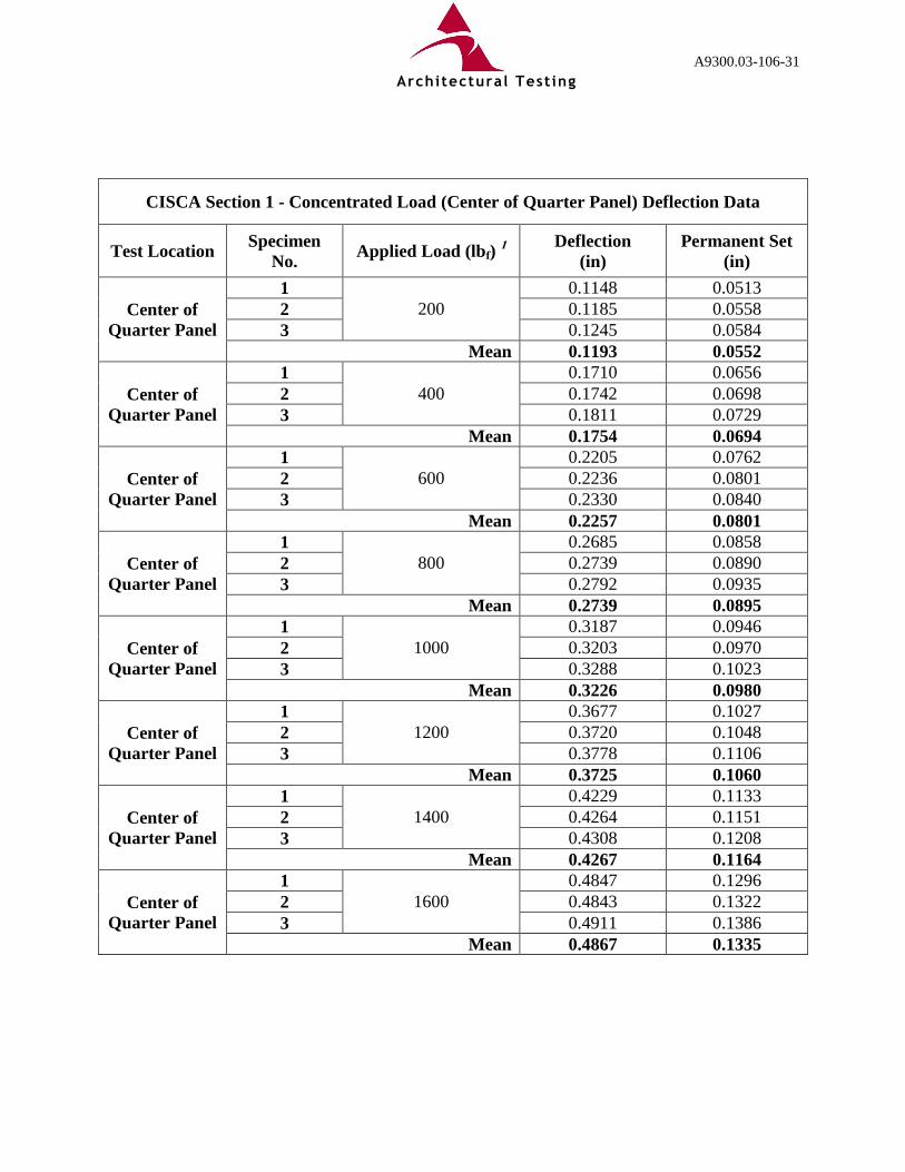
CISCA Section 1 - Concentrated Load (Center of Quarter Panel) Deflection Data
Test Location Specimen
No. Applied Load (lbf)
1
Deflection
(in)
Permanent Set
(in)
Center of
Quarter Panel
1
200
0.1148 0.0513
2 0.1185 0.0558
3 0.1245 0.0584
Mean 0.1193 0.0552
Center of
Quarter Panel
1
400
0.1710 0.0656
2 0.1742 0.0698
3 0.1811 0.0729
Mean 0.1754 0.0694
Center of
Quarter Panel
1
600
0.2205 0.0762
2 0.2236 0.0801
3 0.2330 0.0840
Mean 0.2257 0.0801
Center of
Quarter Panel
1
800
0.2685 0.0858
2 0.2739 0.0890
3 0.2792 0.0935
Mean 0.2739 0.0895
Center of
Quarter Panel
1
1000
0.3187 0.0946
2 0.3203 0.0970
3 0.3288 0.1023
Mean 0.3226 0.0980
Center of
Quarter Panel
1
1200
0.3677 0.1027
2 0.3720 0.1048
3 0.3778 0.1106
Mean 0.3725 0.1060
Center of
Quarter Panel
1
1400
0.4229 0.1133
2 0.4264 0.1151
3 0.4308 0.1208
Mean 0.4267 0.1164
Center of
Quarter Panel
1
1600
0.4847 0.1296
2 0.4843 0.1322
3 0.4911 0.1386
Mean 0.4867 0.1335
Architectural Testing

A9300.03-106-31
CISCA Section 1 - Concentrated Load (Center of Quarter Panel) Deflection Data
(Continued)
Test Location Specimen
No. Applied Load (lbf)
1
Deflection
(in)
Permanent Set
(in)
Center of
Quarter Panel
1
1800
0.6589 0.2013
2 0.9186 0.2368
3 0.9392 0.2461
Mean 0.8389 0.2281
Center of
Quarter Panel
1
2000
0.8326 0.2548
2 1.1516 0.2869
3 1.1478 0.2820
Mean 1.0440 0.2745
Center of
Quarter Panel
1
2200
0.9577 0.2780
2 1.4907 0.4532
3 1.3405 0.3690
Mean 1.2630 0.3667
Center of
Quarter Panel
1
2400
1.0999 0.3103
2 Failure -
3 Failure -
Mean 1.0999 0.3103
Center of
Quarter Panel
1
2600
1.3408 0.3978
2 - -
3 - -
Mean 1.3408 0.3978 1 Applied load was applied in 200 lbf increments, held for one minute, incremental peak deflection measured and
released to allow for incremental permanent set determination.
CISCA Section 1 - Concentrated Load (Center of Quarter Panel) Peak Load Data
Test Location Specimen
No.
Load at Failure
(lbf) Mode of Failure
Center of
Quarter Panel
1 2648.05 Panel Fracture
2 2386.31 Panel Fracture
3 2200.99 Panel Fracture
Mean 2411.78 Panel Fracture
Architectural Testing

A9300.03-106-31
CISCA Section 1 - Concentrated Load (Quarter Panel Midpoint Edge) Deflection Data
Test Location Specimen
No. Applied Load (lbf)
1
Deflection
(in)
Permanent Set
(in)
Quarter Panel
Midpoint
Edge
1
200
0.1184 0.0521
2 0.1255 0.0536
3 0.1226 0.0512
Mean 0.1222 0.0523
Quarter Panel
Midpoint
Edge
1
400
0.1854 0.0655
2 0.1975 0.0682
3 0.1926 0.0661
Mean 0.1918 0.0666
Quarter Panel
Midpoint
Edge
1
600
0.2491 0.0761
2 0.2672 0.0793
3 0.2588 0.0767
Mean 0.2584 0.0774
Quarter Panel
Midpoint
Edge
1
800
0.3165 0.0852
2 0.3389 0.0904
3 0.3387 0.0882
Mean 0.3314 0.0879
Quarter Panel
Midpoint
Edge
1
1000
0.3908 0.0968
2 0.4185 0.1057
3 0.4318 0.1064
Mean 0.4137 0.1029
Quarter Panel
Midpoint
Edge
1
1200
0.4781 0.1188
2 0.5168 0.1342
3 0.5675 Failure
Mean 0.5208 0.1265
Quarter Panel
Midpoint
Edge
1
1400
0.5889 0.1601
2 0.6456 0.1886
3 - -
Mean 0.6173 0.1743
Architectural Testing

A9300.03-106-31
CISCA Section 1 - Concentrated Load (Quarter Panel Midpoint Edge) Deflection Data
(Continued)
Test Location Specimen
No. Applied Load (lbf)
1
Deflection
(in)
Permanent Set
(in)
Quarter Panel
Midpoint
Edge
1
1600
0.8858 Failure
2 0.8311 0.2824
3 - -
Mean 0.8584 0.2824
Quarter Panel
Midpoint
Edge
1
1800
- -
2 1.5119 Failure
3 - -
Mean 1.5119 - 1 Applied load was applied in 200 lbf increments, held for one minute, incremental peak deflection measured and
released to allow for incremental permanent set determination.
CISCA Section 1 - Concentrated Load (Quarter Panel Midpoint Edge) Peak Load Data
Test Location Specimen
No.
Load at Failure
(lbf) Mode of Failure
Quarter Panel
Midpoint
Edge
1 1601.14 Panel Fracture
2 1801.16 Panel Fracture
3 1201.20 Panel Fracture
Mean 1534.50 Panel Fracture
Architectural Testing

A9300.03-106-31
CISCA Section 2 - Ultimate Load Comprehensive Data
Test Location Specimen
No.
Loading
Area
(in2)
Ultimate Failure
Load
(lbf)
Mode of Failure
Full Panel
Center
1
1.0
6039.7 Quarter Panel Kick Out
2 5994.7 Quarter Panel Kick Out
3 5722.5 Quarter Panel Kick Out
Mean 5919.0 Quarter Panel Kick Out
Center of
Quarter Panel
1
1.0
2941.8 Panel Fracture
2 1959.0 Panel Fracture
3 2999.0 Panel Fracture
Mean 2633.3 Panel Fracture
Quarter Panel
Midpoint
Edge
1
1.0
1745.0 Panel Fracture
2 1841.9 Panel Fracture
3 1364.8 Panel Fracture
Mean 1650.6 Panel Fracture
CISCA Section 3 - Rolling Load (Wheel A - 10 Pass Test) Comprehensive Data
Travel Path
Applied Load
(lbf)
Measured Deformation
No. Location
Beam Deformation Local Deformation
Initial Post-
Cycling Initial
Post-
Cycling
1 Full Panel
Center 800 0.000 0.000 0.000 0.000
2 Quarter
Panel Center 800 0.000 0.000 0.000 0.000
Architectural Testing

A9300.03-106-31
ASTM D 635 - Rate of Burn
Specimen Initial
Burn
Sustained Burn
Beyond 30 sec
or 25 mm
Length
Burned, L
(mm)
Time, t
(sec)
Linear Burn
Rate, V
(mm/min)
Comments
1 Yes No 0 30 0
The flame did
not reach or
pass the 25
mm gage
mark for any
specimen
tested
2 Yes No 0 30 0
3 Yes No 0 30 0
4 Yes No 0 30 0
5 Yes No 0 30 0
6 Yes No 0 30 0
7 Yes No 0 30 0
8 Yes No 0 30 0
9 Yes No 0 30 0
10 Yes No 0 30 0 Average Linear Burning Rate, V = 0 mm/min
Rate of Burn Classification: CC1
Satisfies performance criteria presented in Miami Dade County Checklist #0445 For the Approval of: Plastic and
Foam Plastic. Caveat: This standard is used to measure and describe the response of materials, products, or
assemblies to heat and flame under controlled conditions but does not by itself incorporate all
factors required for fire hazards or fire risk assessment of materials, products, or assemblies
under actual fire conditions.
Architectural Testing

A9300.03-106-31
ASTM D 1929 - Self Ignition
Specimen
Initial
Mass
(g)
Final
Mass
(g)
Mass
Loss
(g)
Initial Temperature
(ºC)
Final Temperature
(ºC)
Air Furnace Sample Air Furnace Sample
1 2.7516 0.1387 2.6129 550.0 668.7 494.2 562.1 668.8 606.9
2 2.6819 0.2419 2.4400 589.9 713.8 524.6 644.5 713.9 605.9
3 3.0261 0.2020 2.8241 569.8 683.0 526.4 589.2 683.0 604.3
4 2.6658 0.2630 2.4028 580.2 681.6 540.1 602.3 681.7 602.7
Specimen Ignition Combustion
Type
Observations
(min:sec)
Char Melt Bubble Foam Smoke Soot
1 No -- -- -- -- 0:41 1:22 --
2 Yes Flame -- -- -- 0:26 0:57 1:20
3 No -- -- -- -- 0:25 1:02 --
4 Yes Flame -- -- -- 0:27 0:58 1:32
Self Ignition Temperature: 580 ºC
Satisfies performance criteria presented in Miami Dade County Checklist #0445 For the Approval of: Plastic and
Foam Plastic.
ASTM D 1929 - Flash Ignition
Specimen
Initial
Mass
(g)
Final
Mass
(g)
Mass
Loss
(g)
Initial Temperature
(ºC)
Final Temperature
(ºC)
Air Furnace Sample Air Furnace Sample
1 3.6451 0.5553 3.0898 449.9 555.2 383.9 483.9 555.4 464.7
2 3.2170 0.5676 2.6494 429.1 517.9 343.9 433.0 517.8 452.1
3 3.1259 1.2150 1.9109 411.8 504.8 295.4 421.8 505.3 436.7
4 3.3243 2.1222 1.2021 389.6 480.8 272.4 396.7 479.9 409.2
5 2.7366 1.8948 0.8418 379.9 466.4 250.2 382.4 466.5 376.4
Specimen Ignition Combustion
Type
Observations
(min:sec)
Char Melt Bubble Foam Smoke Soot
1 Yes Flame -- -- -- 1:02 3:26 --
2 Yes Flame -- -- -- 1:06 3:49 --
3 Yes Flame -- -- -- 0:57 4:35 --
4 Yes Flame -- -- -- 0:59 7:30 --
5 No -- -- -- -- 1:16 7:32 --
Flash Ignition Temperature: 390 ºC
Caveat: These test results relate only to the behavior of test specimens under the particular
conditions of the test. They are not intended to be used, and shall not be used, to assess the
potential fire hazards of a material in use.
Architectural Testing

A9300.03-106-31
ASTM D 2843 - Smoke Density
Specimen Width
(in)
Length
(in)
Thickness
(in)
Maximum
Smoke Density
(%)
Smoke Density
Rating
1 0.908 0.907 0.276 53.35 39.3
2 0.912 0.907 0.276 60.11 43.8
3 0.908 0.905 0.276 44.15 32.2
Average Smoke Density Rating: 38.4
Satisfies performance criteria presented in Miami Dade County Checklist #0445 For the Approval of: Plastic and
Foam Plastic.
Note: During all smoke density tests, the letters on the exit sign were visible and readable
through the smoke.
Caveat: This standard should be used to measure and describe the response of materials,
products, or assemblies to heat and flame under controlled laboratory conditions and should not
be used to describe or appraise the fire-hazard or fire-risk of materials, products, or assemblies
under actual fire conditions. However, results of this test may be used as elements of a
fire-hazard assessment or a fire risk assessment which takes into account all of the factors which
are pertinent to an assessment of the fire hazard or fire-risk of a particular end use.
Full Panel Load Bearing Area Failure Load Evaluation
Specimen
No.
Panel Load
Bearing Area
(in2)
Failure Load
(lbf)
Load per Unit
Area
(psi)
Ultimate Distributed
Load
(psf)
1
95.06
35,743 376 54,144
2 35,871 377 54,338
3 36,067 379 54,635
4 36,867 388 55,846
5 34,829 366 52,759
Mean 95.06 35,876 377 54,344
Architectural Testing

A9300.03-106-31
ASTM E 2322, Uniform Load/Deformation Evaluation - Deflection Under Load
Pressure
(psf)
Specimen No. Mean
Deformation (in) 1 2 3 4 5 6
50 0.02 0.02 0.01 0.01 0.02 0.03 0.02
100 0.04 0.03 0.03 0.02 0.04 0.04 0.03
150 0.05 0.04 0.04 0.03 0.05 0.05 0.04
200 0.06 0.05 0.06 0.05 0.06 0.07 0.06
250 0.09 0.07 0.07 0.06 0.08 0.08 0.08
300 0.09 0.07 0.08 0.07 0.09 0.09 0.08
320 0.09 0.08 0.09 0.07 0.09 0.10 0.09
350 0.10 0.08 0.10 0.07 0.09 0.10 0.09
400 0.10 0.08 0.09 0.08 0.10 0.11 0.09
450 0.11 0.09 0.11 0.09 0.10 0.11 0.10
500 0.11 0.09 0.11 0.09 0.11 0.12 0.11
550 0.12 0.11 0.12 0.11 0.11 0.13 0.12
600 0.12 0.11 0.13 0.11 0.11 0.13 0.12
650 0.13 0.11 0.13 0.11 0.12 0.14 0.12
700 0.13 0.10 0.13 0.11 0.11 0.13 0.12
750 0.14 0.11 0.13 0.12 0.12 0.14 0.13
800 0.14 0.11 0.14 0.12 0.12 0.14 0.13
850 0.15 0.12 0.15 0.12 0.13 0.15 0.14
900 0.15 0.12 0.15 0.13 0.13 0.15 0.14
950 0.16 0.12 0.15 0.13 0.13 0.14 0.14
1000 0.16 0.13 0.16 0.13 0.14 0.15 0.15
1050 0.17 0.13 0.16 0.13 0.14 0.15 0.15
1100 0.17 0.13 0.15 0.13 0.13 0.15 0.14
1150 0.18 0.13 0.16 0.13 0.14 0.15 0.15
1200 0.18 0.14 0.16 0.14 0.14 0.15 0.15
1250 0.19 0.16 0.16 0.15 0.15 0.18 0.17
1300 0.20 0.14 0.17 0.12 0.15 0.12 0.15
1350 0.20 0.14 0.17 0.12 0.15 0.13 0.15
1400 0.20 0.17 0.16 0.13 0.14 0.16 0.16
Architectural Testing

A9300.03-106-31
ASTM E 2322, Uniform Load/Deformation Evaluation - Permanent Set
Pressure
(psf)
Specimen No. Mean
Deformation (in) 1 2 3 4 5 6
50 <0.01 <0.01 <0.01 <0.01 <0.01 <0.01 <0.01
100 0.01 <0.01 0.01 <0.01 0.01 0.01 0.01
150 0.01 0.01 0.01 0.01 0.01 0.01 0.01
200 0.02 0.01 0.02 0.01 0.02 0.03 0.02
250 0.04 0.03 0.04 0.03 0.04 0.04 0.04
300 0.04 0.03 0.04 0.03 0.04 0.04 0.04
320 0.04 0.03 0.04 0.04 0.04 0.05 0.04
350 0.04 0.03 0.04 0.04 0.04 0.05 0.04
400 0.05 0.04 0.05 0.04 0.04 0.06 0.05
450 0.05 0.04 0.05 0.05 0.05 0.06 0.05
500 0.05 0.04 0.05 0.05 0.05 0.06 0.05
550 0.05 0.04 0.06 0.05 0.05 0.06 0.05
600 0.05 0.04 0.06 0.05 0.05 0.07 0.05
650 0.06 0.04 0.06 0.05 0.05 0.07 0.06
700 0.06 0.04 0.06 0.06 0.06 0.07 0.06
750 0.06 0.04 0.06 0.06 0.06 0.07 0.06
800 0.06 0.04 0.06 0.06 0.06 0.08 0.06
850 0.06 0.04 0.07 0.06 0.06 0.08 0.06
900 0.06 0.04 0.06 0.06 0.06 0.08 0.06
950 0.06 0.04 0.07 0.06 0.06 0.08 0.06
1000 0.07 0.05 0.07 0.07 0.06 0.08 0.07
1050 0.07 0.05 0.07 0.07 0.06 0.09 0.07
1100 0.07 0.05 0.07 0.07 0.06 0.09 0.07
1150 0.08 0.05 0.08 0.06 0.06 0.09 0.07
1200 0.08 0.05 0.08 0.07 0.07 0.09 0.07
1250 0.08 0.05 0.087 0.07 0.07 0.10 0.08
1300 0.08 0.05 0.08 0.05 0.07 0.05 0.06
1350 0.08 0.05 0.08 0.05 0.07 0.05 0.06
1400 0.09 0.06 0.10 0.06 0.07 0.09 0.08
Architectural Testing

A9300.03-106-31
APPENDIX B
Smoke Density Light Absorption Curves
Architectural Testing


A9300.03-106-31
APPENDIX C
Photographs
Architectural Testing

A9300.03-106-31
Photo No. 1
Typical Fixed Height Low Profile Raised Floor System Panel Specimens As-Received
Photo No. 2
Typical Pretest Condition Quarter Panel Detail
Architectural Testing

A9300.03-106-31
Photo No. 3 CISCA Sections 1 and 2 - Full Panel Center Point Loading Test Setup
Photo No. 4 CISCA Sections 1 and 2 - Full Panel Center Point Loading Test in Progress
Architectural Testing

A9300.03-106-31
Photo No. 5 CISCA Sections 1 and 2 - Full Panel Center Point Loading Test Kick Out Failure
Photo No. 6 CISCA Sections 1 and 2 - Full Panel Center Point Loading Test Underside Failure Detail
Architectural Testing

A9300.03-106-31
Photo No. 7 CISCA Sections 1 and 2 - Center of Quarter Panel Loading Test Setup
Photo No. 8 CISCA Sections 1 and 2 - Center of Quarter Panel Loading Test in Progress
Architectural Testing

A9300.03-106-31
Photo No. 9 CISCA Sections 1 and 2 - Center of Quarter Panel Loading Test Panel Fracture Failure
Photo No. 10 CISCA Sections 1 and 2 - Center of Quarter Panel Underside Failure Detail
Architectural Testing

A9300.03-106-31
Photo No. 11 CISCA Sections 1 and 2 - Quarter Panel Midpoint Edge Loading Test Setup
Photo No. 12 CISCA Sections 1 and 2 - Quarter Panel Midpoint Edge Loading Test in Progress
Architectural Testing

A9300.03-106-31
Photo No. 13
CISCA Sections 1 and 2 - Quarter Panel Midpoint Edge Loading Test Panel
Fracture Failure
Photo No. 14
CISCA Section 3 - Rolling Load Test Apparatus
Architectural Testing

A9300.03-106-31
Photo No. 15
CISCA Section 3 - Travel Path 1 (Full Panel Center) Post-Cycling Specimen Condition
Photo No. 16
CISCA Section 3 - Travel Path 2 (Quarter Panel Center) Post-Cycling Specimen Condition
Architectural Testing

A9300.03-106-31
Photo No. 17
CISCA Section 3 - Post-Cycling Beam Deformation Measurement
Photo No. 18
CISCA Section 3 - Post-Cycling Local Deformation Measurement
Architectural Testing

A9300.03-106-31
Photo No. 19 ASTM D 635 - Rate of Burn Test Setup
Photo No. 20 ASTM D 635 - Flame Exposure Detail
Architectural Testing

A9300.03-106-31
Photo No. 21 ASTM D 635 - Typical Post Exposure Specimen Detail
Photo No. 22
ASTM D 1929 - Typical Pretest Condition Ignition Specimens
Architectural Testing

A9300.03-106-31
Photo No. 23
ASTM D 1929 - Typical Post-Ignition Specimen Condition
Photo No. 24
ASTM D 2643 - Typical Pretest Condition Smoke Density Specimens
(Specimens Were Stacked to Achieve Required Test Thickness)
Architectural Testing

A9300.03-106-31
Photo No. 25
ASTM D 2643 - Smoke Density Test Apparatus
Photo No. 26
ASTM D 2643 - Typical Post-Exposure Condition Smoke Density Specimen
Architectural Testing

A9300.03-106-31
Photo No. 27
ASTM E 2322 - Uniform Load Evaluation Test Fixture
Photo No. 28
ASTM E 2322 - Typical Posttest Condition Uniform Load Specimen
(No Damage Observed Post 1,600 psf Applied Load)
Architectural Testing

A9300.03-106-31
Photo No. 29 Full Panel Load Bearing Area Failure Load Evaluation Test Setup
Photo No. 30
Typical Full Panel Load Bearing Area Failure Load Evaluation Compressive Failure Detail
Architectural Testing