Embed Size (px)
Citation preview

1
Performance Evaluation of VeMAC SupportingSafety Applications in Vehicular Networks
Hassan Aboubakr Omar, Student Member, IEEE, Weihua Zhuang, Fellow, IEEE,Atef Abdrabou, Member, IEEE, and Li Li, Member, IEEE
Abstract—Vehicular ad hoc networking is an emerging paradigm which is expected to increase the public safety standards andenhance the safety level of drivers/passengers and pedestrians on road through a variety of applications. We have recently proposedVeMAC, a medium access control protocol which supports a reliable one-hop broadcast service necessary for high priority safetyapplications in VANETs [1], [2], [3]. This paper explains how the VeMAC protocol can deliver both periodic and event-driven safetymessages in vehicular networks, and presents a detailed delivery delay analysis, including queueing and service delays, for both typesof safety messages. The probability mass function of the service delay is first derived, then the D/G/1 and M/G/1 queueing systemsare used to calculate the average queueing delay of the periodic and event-driven safety messages respectively. As well, a comparisonbetween the VeMAC protocol and the IEEE 802.11p standard [4] is presented via extensive simulations using the network simulatorns-2 [5] and the microscopic vehicle traffic simulator VISSIM [6]. A real city scenario is considered and different performance metricsare evaluated, including the network goodput, protocol overhead, channel utilization, protocol fairness, probability of a transmissioncollision, and message delivery delay.
Index Terms—TDMA, medium access control, delay analysis, safety messages, and vehicular ad hoc networks.
F
1 INTRODUCTION
A Vehicular ad-hoc network (VANET) is a specialtype of mobile ad-hoc networks, which consists of
a set of vehicles, equipped with a communication devicecalled on-board unit (OBU), and a set of stationary unitsalong the road, referred to as road side units (RSUs).Each vehicle OBU has a wireless network interface whichallows the vehicle to directly connect to other vehiclesand RSUs within its communication range. Some RSUscan act as a gateway for connectivity to other com-munication networks, such as the Internet. Based onthese vehicle-to-vehicle (V2V) and vehicle-to-RSU (V2R)communications, VANETs can support a wide variety ofapplications in road safety, passenger infotainment, andvehicle traffic optimization [8], [9]. The primary categoryof VANET applications is to enhance the public safetystandards and provide a safer environment for peopleon road, which is the main reason that VANETs have re-ceived significant support from government, academia,and industrial organizations over the globe. The Vehicle
• H. A. Omar and W. Zhuang are with the Center for Wireless Com-munications, Department of Electrical and Computer Engineering, Uni-versity of Waterloo, 200 University Avenue West, Waterloo, Ontario,Canada, N2L 3G1.E-mail: {h3omar,wzhuang}@uwaterloo.ca
• A. Abdrabou is with the Department of Electrical Engineering, UAEUniversity, Al-Ain, Abu Dhabi, UAE.E-mail: [email protected]
• L. Li is with the Communications Research Center, Ottawa, Ontario,Canada, K2H 8S2.E-mail: [email protected]
This work is submitted in part to IEEE GlOBECOM 2013 [7].This work was supported by a research grant from the Natural Science andEngineering Research Council (NSERC) of Canada.
Safety Communications (VSC) project [9] is establishedby seven car manufacturers (including GM, BMW, andFord), in partnership with the United States Depart-ment of Transportation (USDoT), in order to estimatethe potential benefits of VANET safety applications anddefine their communication requirements. In the VSCproject, the VANET safety applications are classified intoperiodic and event-driven safety applications, based onthe way that the corresponding safety messages aretransmitted by each node (i.e., vehicle or RSU). Theperiodic safety applications (e.g., blind spot warning) re-quire automatic transmission of safety messages by eachnode at regular time intervals, while the event-drivensafety applications (e.g., pre-crash sensing [9]) requiretransmission of safety messages only in case of an eventsuch as a hard brake, approaching an emergency vehicle,and dangerous road condition detection.
Most (if not all) of the safety applications, eitherperiodic or event-driven, are based on one-hop broad-casting of safety messages to all the nodes within thecommunication range. For instance, an application suchas the emergency electronic brake light [9] requireseach vehicle to broadcast information about its position,speed, acceleration, etc., to all the vehicles within its one-hop neighbourhood. Similarly, for an application suchas the traffic signal violation warning [9], an RSU nearthe traffic signal should broadcast to all the comingvehicles information related to the traffic light status andtiming, road surface type, weather conditions, stoppingposition, and so on. Given that any inaccuracy in thebroadcasted safety messages may result in serious con-sequences, such as vehicles damage or drivers injuries,it is necessary that a medium access control (MAC)

2
protocol proposed for VANETs provides an efficientone-hop broadcast service to support the quality-of-service (QoS) requirements of the high priority safetyapplications. The IEEE 802.11p is a current standardproposed for MAC in VANETs [4]. However, as will beshown in this paper, the standard does not provide anefficient one-hop broadcast service. Different works havebeen done to evaluate/enhance the performance of theIEEE 802.11p standard [10], [11], [12]. For instance, in[10], [11], mathematical analysis is presented to modelthe IEEE 802.11p enhanced distributed channel access(EDCA) scheme for single-transceiver nodes, while in[12], an extension to the EDCA scheme is proposed tosupport the QoS requirements of the non-safety relatedVANET applications. On the other hand, the VeMAC isa time division multiple access (TDMA) protocol thatwe recently proposed for MAC in VANETs to supporta reliable one-hop broadcast service [1], [2], [3]. TheVeMAC is designed specifically for a VANET scenarioover the physical layer of different standards, includ-ing IEEE 802.11p. The protocol supports multichanneloperation over one control channel (CCH) and multipleservice channels (SCHs) to be consistent with the sevendedicated short range communication (DSRC) channelsspecified by the Federal Communications Commission(FCC) for V2V and V2R communications.
The main objectives of this paper are to define how theVeMAC protocol serves the periodic and event-drivensafety messages, to analyze the total delivery delay ofboth types of safety messages, which is a crucial QoSmetric for VANET safety applications, and to present adetailed comparison between the VeMAC protocol andthe IEEE 802.11p standard in a realistic city scenario,using various performance metrics. Different from theprevious works [1], [2], [3], this paper defines two dif-ferent VeMAC protocol data units (exchanged betweentwo peer VeMAC entities) and describes the necessarytechniques for each node to access multiple time slots ina time frame on the CCH. This flexibility in the numberof time slots that a node is allowed to access on the CCHcan be useful to support the safety applications witha large message size or stringent delay requirements.Based on the results in this paper, the VeMAC protocolparameters can be determined to satisfy the QoS require-ments of periodic and event-driven safety applications(which is necessary for the hardware implementationand real testing of the protocol in the future).
The rest of the paper is organized as follows: Section 2describes the system model and Section 3 discussesdetails of the VeMAC protocol to support safety ap-plications. The delay analysis of periodic and event-driven safety messages is presented in Section 4 andthe numerical results are given in Section 5. Section 6compares the performances of the VeMAC protocol withthat of the IEEE 802.11p standard via simulations in asquare network and a realistic city scenario, and finallySection 7 concludes this study and suggests some furtherresearch topics.
Fig. 1: Right and left directions of vehicle movement.
2 SYSTEM MODEL
The VANET under consideration consists of a set ofRSUs and a set of vehicles moving in opposite directionson two-way vehicle traffic roads, as shown in Fig. 1. Avehicle is said to be moving in a left (right) direction if itis currently heading to any direction from north/south towest (east). Based on this definition, as shown in Fig. 1, iftwo vehicles are moving in opposite directions on a two-way road, regardless of the orientation of the road, it isguaranteed that one vehicle is moving in a left directionwhile the other vehicle is moving in a right one. Thevehicles and RSUs broadcast periodic and event-drivensafety messages for the purpose of safety applications. Atwo-hop set (THS) is defined as a set of nodes in whicheach node can reach any other node in two hops at most.In this paper, the term ‘packet’ refers to a MAC layerprotocol data unit, while the term ‘message’ refers to aMAC layer service data unit (MSDU), i.e., the unit ofinformation arriving to the MAC layer entity from thelayer above. The periodic safety messages broadcastedby different vehicles have the same (fixed) message size1.Similarly, the periodic safety messages broadcasted byan RSU have equal message size, which may differ fromthe size of the periodic messages broadcasted by anotherRSU depending on the application.
The VANET has one CCH and multiple SCHs. Eachnode has two transceivers, one is always tuned to theCCH, while the other switches among the SCHs. Al-though the VeMAC is a multichannel protocol, this paperfocuses only on the operation of the VeMAC on the CCH,over which the high priority periodic and event-drivensafety messages under consideration are transmitted. Asshown in Fig. 2, the periodic and event-driven safetymessages are mapped to two different queues, whichare served independently by the VeMAC protocol, asdescribed in details in Section 3. The time is partitionedto frames consisting of a constant number S of equal-duration time slots. Based on a given transmission ratedetermined by the physical layer, the VeMAC maximumtransmission unit (MTU) is defined as the maximumamount of data (without the physical layer overhead)which can be transmitted in the duration of one time
1. A generic safety message format, called the Basic Safety Message(BSM), is specified in the SAE J2735 application layer standard [13] tobe periodically broadcasted by vehicles. The BSM exploits the largeoverlap among the vehicle state information required by various V2Vapplications in order to avoid using application-specific messages andwasting the wireless network resources [14].

3
Fig. 2: Safety message queues.
Fig. 3: Partitioning of each frame into L,R and F sets.
slot. The duration of a time slot is chosen such that theMTU is equal to the size of a periodic safety messagebroadcasted by a vehicle plus the maximum size ofcontrol information introduced by the VeMAC protocol.For RSUs, if the size of a periodic safety message plus theVeMAC control information exceeds the MTU, the mes-sage is fragmented to be transmitted as multiple VeMACpackets, as indicated in Fig. 2. This fragmentation istypical for applications such as curve speed warning andleft turn assistant [9], in which the size of a periodicsafety message broadcasted by an RSU is considerablylarger than that of the periodic messages broadcastedby vehicles [9]. On the other hand, all the event-drivensafety messages are assumed to be small enough to fitin a single VeMAC packet, without fragmentation. EachVeMAC packet carries at most one safety message andonly one VeMAC packet can be transmitted per timeslot. Each second contains an integer (fixed) number offrames, and each frame is partitioned into three setsof time slots: L, R, and F , in that order, as shown inFig. 3. The F set is reserved for RSUs, while the L andR sets are associated with vehicles moving in left andright directions respectively. Each time slot is identifiedby the index of the time slot within a frame (the indexstarts from 0 to S − 1), and each node is identified by aunique MAC address and a set of short identifiers (IDs).Each node ID corresponds to a certain time slot that thenode is accessing per frame on the CCH (more detailsin Section 3). For a certain node, x, the following twosets are defined: a) N(x): the set of IDs of the one-hopneighbours of node x on the CCH, from which node xhas received packets on the CCH in the previous S slots;b) T (x): the set of time slots that node x must not useon the CCH in the next S time slots. The set, T (x),is used by node x to determine which time slots it canaccess on the CCH without causing any hidden terminalproblem. How each node x constructs and updates theset is discussed in Section 3 as follows.
3 VEMAC PROTOCOL
3.1 VeMAC Basics
In the VeMAC protocol, in order to serve the two safetymessage queues in Fig. 2, each node must acquire at leastone time slot per frame on the CCH. A time slot acquiredby a certain node is referred to as a periodic or event-driven slot, according to the type of the safety messagetransmitted during this time slot. The number of periodicslots that the node acquires per frame, denoted by kp, isconstant and depends on the fixed size and arrival rateof the periodic safety messages. Similarly, the numberof event-driven slots that the node can access per frame,denoted by ke, is constant and depends on the averagearrival rate of the event-driven safety messages. A nodeshould use a unique node ID to access each of the kp andke slots. Each node ID is chosen by the node at random,included in the header of each packet transmitted inthe corresponding time slot, and changed if the nodedetects that its ID is already in use by another node [15].The kp and ke values are chosen such as to satisfythe delay constraints of the periodic and event-drivensafety messages based on the delay analysis in Section 4.Once a node acquires a periodic or event-driven slot,it keeps using the same slot in all subsequent framesunless there is no packet waiting for transmission inthe corresponding queue or a transmission collision isdetected. Two types of transmission collision can happenon the CCH [2]: access collision and merging collision.An access collision happens when two or more membersof the same THS attempt to acquire the same availabletime slot. On the other hand, a merging collision happenswhen two or more nodes acquiring the same time slotbecome members of the same THS due to node activa-tion or node mobility. In VANETs, merging collisions aremore likely to occur among vehicles moving in oppositedirections or between a vehicle and a stationary RSUsince they approach each other with a much higherrelative velocity as compared to vehicles moving in thesame direction.
Two different types of VeMAC packets can be trans-mitted on the CCH, as shown in Fig. 4. A Type1 packet isdivided into four main fields: Type1 header, announce-ment of services (AnS), acceptance of services (AcS), andhigh priority safety applications (HPSA). The HPSA fieldis to include the periodic and event-driven safety mes-sages, while the AnS and AcS fields are used to controlthe communications over the SHCs [2]. A Type2 packetdoes not contain any control information: it consists ofan HPSA field and a short Type2 header (the differencebetween Type1 and Type2 headers will be discussed).Each node must transmit exactly one Type1 packet ineach frame using one of its acquired periodic time slots,and if the node is accessing more than one time slotper frame, Type2 packets are transmitted over the restof time slots. The transmission of one Type1 packet ineach frame is mandatory since the information in theType1 header, AnS and AcS fields, is necessary for other

4
(a) Type1 packet.
(b) Type2 packet.
Fig. 4: VeMAC packet types.
nodes to decide which time slots they can access on theSCHs [2] and CCH. On the other hand, the transmissionof Type2 packets is to decrease the protocol overheadby removing all the control information which needsto be transmitted only once per frame. As the event-driven safety messages are always transmitted usingType2 packets (i.e., without control information and witha large HPSA field in the packet), fragmentation is notconsidered for this type of safety messages.
3.2 Accessing Slots on the CCH
For the purpose of time slot assignment on the CCH,in the header of each Type1 packet transmitted on theCCH, the transmitting node y should include set N(y)and the time slot corresponding to each node ID in setN(y). Note that, different node IDs in set N(y) maycorrespond to a single one-hop neighbour of node ywhich is accessing multiple time slots per frame. Theshort IDs in set N(y) serve to decrease the overhead ascompared to including the MAC address of each one-hop neighbour in the header of each transmitted Type1packet. The main difference between Type1 and Type2headers is that the Type2 one is shorter as it does notcontain the set N(y) or the corresponding time slots.Suppose node x is just powered on and needs to acquirea time slot. It starts listening to the CCH for S successivetime slots (not necessarily in the same frame). At the endof the S slots, node x can determine N(x) and the timeslot corresponding to each node ID in N(x). In addition,since each one-hop neighbour w of node x announces(in the header of its transmitted Type1 packet) the setN(w) and the time slot corresponding to each node IDin N(w), node x can determine all the time slots used byeach of its two-hop neighbours. Accordingly, node x setsT (x) to the set of time slots used by all nodes within itstwo-hop neighbourhood. Then, sets N(x) and T (x) areupdated by node x at the end of each time slot (alwaysbased on the packets received in the previous S slots).
Given T (x), node x determines the set of accessibletime slots, A(x), (to be discussed) and then attempts toacquire a time slot by randomly accessing any time slotin A(x), say time slot k. If no other node in the two-hop neighbourhood of node x simultaneously attemptsto acquire time slot k, then no access collision happens.In this case, the attempt of node x is successful andeach one-hop neighbour w of node x adds node x’s ID(denoted by IDx) to set N(w) and records that time slotk corresponds to IDx. On the other hand, if at leastone node within the two-hop neighbourhood of nodex accesses time slot k, then all the transmissions in theslot fail and time slot k is not acquired by any of the con-
tending nodes. Node x will determine whether or not itsattempt was successful by observing the S−1 time slotsfollowing k. The attempt of node x is considered suc-cessful iff the Type1 packets received from each node w,with IDw ∈ N(x), indicate that IDx ∈ N(w). Otherwise,node x re-accesses one of the time slots in A(x) until itsuccessfully acquires a time slot. Once node x acquires atime slot, it keeps using the same slot in all subsequentframes unless a merging collision happens. Similar toan access collision, a merging collision is detected bynode x as soon as it receives a Type1 packet from anode w, with IDw ∈ N(x), indicating that IDx /∈ N(w).Upon detection of a merging collision, each collidingnode should release its time slot and acquire a new oneusing the same procedure. At the end of each time slot,the collision detection by a certain node x should bedone before updating the set N(x) in order to preventthe nodes from unnecessarily releasing their time slotswhen they just enter the communication range of eachother [2]. In order to acquire more than one time slotper frame, node x employs the same procedure using aunique node ID for accessing each extra time slot.
When a node, x, is attempting to acquire a time slot,a parameter called the split up parameter, denoted by τ ,determines how node x accesses the time slots belongingto the L, R, and F sets. Consider that node x is movingin one of the right directions. Initially, node x limits setA(x) to the available time slots associated with the rightdirections, i.e., A(x) = T (x)∩R. If after τ frames node xcannot acquire a time slot, then node x augments A(x) byadding the time slots associated with the opposite direc-tion, i.e., A(x) = T (x)∩ (R∪L). If, after τ more frames,node x still cannot acquire a time slot, node x will startto access any available time slot, i.e., A(x) = T (x). Thesame procedure applies for a vehicle moving in a leftdirection by replacing R with L. Similarly, if node x isan RSU, for the first τ frames A(x) = T (x)∩F , and thenA(x) = T (x). Note that, when τ = ∞, regardless of thenumber of access collisions that node x has encounteredto acquire a time slot, it can only access the time slotsreserved for its moving direction (i.e., in the R set).On the other extreme, when τ = 0, node x can accessany available time slot on the CCH even if it does notexperience any access collision. The choice of the τ valuecan significantly affect the network throughput and therates of access collisions and merging collisions [2], [3].In the analysis in Section 4, the effect of the τ value onthe delay of periodic and event-driven safety messages isinvestigated for the two extreme cases τ = 0 and τ =∞.
4 DELAY ANALYSIS
The total delay that a safety message experiences on theCCH before reaching all the one-hop neighbours consistsof five components: 1) upper layers delay from the timethat a safety message is generated at the applicationlayer until it is assigned to one of the two queuesin Fig. 2, including the fragmentation time of periodic

5
safety messages; 2) queueing delay between the time thata safety message (or a fragment of a safety message) isassigned to one of the queues in Fig. 2 and the timethat it becomes the head of line (HOL); 3) access delayfrom the time that a safety message (or a fragment ofa safety message) becomes the HOL until the start ofits transmission. This delay is mainly the time spent bythe transmitting node waiting for one of its acquiredperiodic or event-driven time slots; 4) transmission du-ration of a safety packet; 5) propagation delay until thesafety packet completely reaches the farthest one-hopneighbour. The upper layers delay and propagation delay arenot considered in the following analysis since they arenegligible as compared to the other delay components.The transmission duration of any safety packet is assumedto be equal to the duration of one time slot. Note that,the duration of one time slot represents the maximumtransmission duration which can be experienced by asafety packet on the CCH. However, the difference be-tween the maximum and actual transmission durations(fraction of a time slot) is negligible as compared tothe queueing delay and access delay (multiple time slots).The sum of the access delay and transmission duration isreferred to as the service delay. To simplify the analysisof the service delay and queueing delay, denoted by Ws
and Wq respectively, we assume that a node releases itsperiodic or event-driven time slot(s) and acquires a newone(s) after the transmission of each periodic or event-driven safety packet respectively. This assumption guar-antees that the service delays of the successive periodicand event-driven safety messages assigned to the twoqueues in Fig. 2 form two sequences of independentand identically distributed random variables, which isa necessary condition for the application of the D/G/1and M/G/1 queuing systems in Subsection 4.2. Theassumption is reasonable in scenarios with high rates ofaccess collisions and merging collisions, where the nodesfrequently release their time slots and acquire new ones.The total delay, denoted by W , is the sum of Ws and Wq ,and all delays are represented in the unit of a time slot.For any discrete random variable X , the probability massfunction (PMF) and the cumulative distribution function(CDF) are denoted by fX and FX respectively, while thefirst and second moments are denoted by X and X2 re-spectively. If random variable X takes only non-negativeinteger values, its probability generating function (PGF)is denoted by GX(z) = zX =
∑x fX(x)zx, while G′X(z)
denotes ddzGX(z). The service delay and queueing delay are
considered separately in Subsections 4.1 and 4.2 in thefollowing. The accuracy of the analysis in this sectionunder the simplified assumptions has been studied viaMATLAB simulations in [7].
4.1 Service DelaySince the VeMAC protocol serves the two queues inFig. 2 independently using the kp and ke time slots, thePMF fWs
is similar for both queues and differs only dueto the difference between the kp and ke values. Hence,
the PMF fWsis derived in a generic way (i.e., irrespective
of the type of the transmitted safety message) given thatthe transmitting node is accessing k time slots per frame.For the periodic and event-driven safety messages, thePMF fWs
can be calculated just by replacing k in thegeneric fWs
with kp and ke respectively. Let randomvariable J denote the index of the time slot at the startof which a safety message becomes the HOL. Note that,since the transmission delay is equal to 1, if the inter-arrival time of periodic safety messages is an integervalue, it is guaranteed that a periodic message becomesthe HOL at the start of a time slot. On the other hand,due to random arrivals of event-driven safety messageswith non-integer inter-arrival times, it is possible that,when the queue is empty, an arriving event-driven mes-sage becomes the HOL within the duration of a certaintime slot. In this case, we neglect a fraction of time slotin the calculation of the service delay and assume that theevent-driven message becomes the HOL at the start ofthe next slot. Hence, the service delay Ws can take onlyinteger values ranging from 1 to S−k+1. The calculationof fWs
(i), i = 1, ..., S− k+1, is considered separately forthe two extreme values of the split up parameter, τ = 0and τ =∞.
4.1.1 τ = 0
In this case, if a safety message becomes the HOL atthe start of time slot j, the transmitting node can beaccessing any k of the S time slots following (andincluding) time slot j with equal probabilities. Hence,
p(Ws = i|J = j) =CS−ik−1CSk
,
1 ≤ k ≤ S, 1 ≤ i ≤ S − k + 1, 0 ≤ j ≤ S − 1
where Cnk = n!(n−k)!k! . The denominator is the number of
ways that the transmitting node can access k time slotsamong the S time slots following (and including) timeslot j, while the numerator is the number of ways thatone of the k time slots that the node is accessing is theith time slot starting from j, denoted by ja = (j + i −1)modS, and the remaining k−1 time slots are among theS − i time slots following time slot ja. In other words,the numerator is the number of ways that the node isaccessing the ith time slot starting from j but not any ofthe i − 1 time slots following (and including) time slotj. Note that, with τ = 0, the probability p(Ws = i|J = j)is independent of the value of j since the transmittingnode is allowed to access all the available time slots ina frame with equal probabilities. Hence,
fWs(i) =
S−1∑j=0
p(Ws = i|J = j)× fJ(j)
=
S−1∑j=0
CS−ik−1CSk
× fJ(j) =CS−ik−1CSk
,
1 ≤ i ≤ S − k + 1, 1 ≤ k ≤ S.

6
4.1.2 τ =∞Consider that a node is moving in one of the leftdirections. When a safety message becomes the HOL atthe start of time slot j, the transmitting node can be ac-cessing any k time slots in set L with equal probabilities.There is no probability that the node accesses any of thetime slots in sets R and F . Hence, unlike the τ = 0 case,the probability p(Ws = i|J = j) depends on the valueof j.a) For |L| ≤ j ≤ S − 1, we have
p(Ws = i|J = j) =
C|L|−[i−(S−j)]
k−1
C|L|k
, S − j + 1 ≤ i ≤
S − j + 1 + |L| − k,1 ≤ k ≤ |L|,
0, elsewhere.
The denominator represents the total number of waysthat the node can access k slots among the |L| time slots,while the numerator represents the number of wayswhich result in Ws equal to i. Note that, the smallestpossible value of Ws is S − j + 1, since j ∈ R∪F whilethe node cannot access any time slot in set R∪ F .b) For 0 ≤ j ≤ |L| − 1, we have the following two cases• If j < k, we have Ws ≤ |L| − k + 1, since at least
one of the k time slots that the node is accessing isamong the next |L|− j time slots starting from timeslot j. Then
p(Ws = i|J = j) =
C|L|−i
k−1
C|L|k
, 1 ≤ i ≤ |L| − k + 1,
0, elsewhere.
• If j ≥ k, there is a probability that the k time slotsthat the node is accessing are all before time slot j,which results in Ws taking values between S− j+1and S − k + 1. Hence
p(Ws = i|J = j) =
C|L|−i
k−1
C|L|k
, 1 ≤ i ≤ |L| − j,CS−i
k−1
C|L|k
, S − j + 1 ≤ i ≤ S − k + 1,
0, elsewhere.
Given p(Ws = i|J = j) for all 0 ≤ j ≤ S − 1, we have
fWs(i) =
S−1∑j=0
p(Ws = i|J = j)× fJ(j),
1 ≤ i ≤ S − k + 1, 1 ≤ k ≤ |L|.
For a node moving in a left direction, we assume that
fJ(j) =
{1|L| , 0 ≤ j ≤ |L| − 1,
0, elsewhere.
This assumption means that, first, a safety messagecannot become the HOL at the start of time slots in setR∪ F and, second, a safety message becomes the HOLat the start of time slots in set L equally likely. Notethat, although the transmitting node is not allowed toaccess time slots in set R∪F , a safety message still can
become the HOL at the start of a time slot belongingto this set, e.g., when a message arrives at the start of atime slot j ∈ R∪F and finds the queue empty. The sameprocedure in this subsubsection can be used to derivefWs
for a node moving in a right direction or for anRSU.
4.2 Queueing Delay
Although the PMF of the service delay is the same for pe-riodic and event-driven safety messages, their queueingdelays are different due to different arrival patterns forthe two different types of safety messages.
4.2.1 Event-driven Safety Messages
As mentioned in Section 1, the event-driven safety mes-sages are triggered by certain events such as a suddenbrake, road feature notification, approaching an emer-gency vehicle, etc. Given the variety of such events,it is reasonable to assume that their arrival processhas independent and stationary increments, with nogroup arrivals. That is, the numbers of events occurringin disjoint time intervals are independent, the PMFof the number of events occurring in a time intervalonly depends on the length of the interval, and thereis no simultaneous arrival of events. Based on theseproperties, the arrival process of the event-driven safetymessages can be modeled by a Poisson process with rateλ message/slot. Hence, the event-driven safety messagequeue in Fig. 2 is an M/G/1 queue with the service delaydistribution fWs
as derived in Subsection 4.1. Conse-quently, provided that Ws <
1λ , which is the necessary
and sufficient condition for stability of the event-drivensafety message queue [16], by applying the P-K formula[17], we have
Wq =λWs
2
2(1− λWs).
4.2.2 Periodic Safety Messages
Based on the assumption of fixed-size periodic safetymessages, the number of fragments of a periodic safetymessage is assumed to be fixed for a given node. If nfdenotes the number of fragments of a periodic safetymessage for a certain node, the arrival of each periodicsafety message results in a simultaneous arrival of nffragments in the periodic safety message queue in Fig. 2.Consequently, this queue can be modeled as a D/G/1queue with fixed-size batch arrivals. Hence, the queueingdelay that a tagged fragment of a periodic safety messageexperiences consists of two components: the delay sincethe batch (to which the tagged fragment belongs) entersthe queue until the first fragment of the batch becomesthe HOL, plus the service delay of all the fragmentsqueued before the tagged fragment within the batch. Thetwo components of the queueing delay are independentand denoted by Wq1 and Wq2 respectively. Let integer Ndenote the inter-arrival time of periodic safety messages,i.e., the batch inter-arrival time. The PGF of the service

7
0 10 20 30 40 50 60 70 80 90 1000
0.1
0.2
0.3
0.4
0.5
0.6
0.7
0.8
0.9
1
n (slot)
FW
s(n)
k=1
k=2
k=4
k=16
k=8
(a) Split up parameter τ = 0.
0 10 20 30 40 50 60 70 80 90 1000
0.1
0.2
0.3
0.4
0.5
0.6
0.7
0.8
0.9
1
n (slot)
FW
s(n) k=1
k=2
k=16
k=4
k=8
(b) Split up parameter τ = ∞.
Fig. 5: The CDF of the service delay, FWs , for a node moving in a left direction with 100 time slots per frame and 40 time slotsassociated with the left direction, i.e., S = 100 and |L| = 40.
0 50 100 150 200 250 300 350 4000
100
200
300
400
500
600
S (slot)
Ave
rage
tota
l del
ay (
slot
)
τ = 0τ = ∞
N = 150
N = 200
N = 100
Average service delay
(a) Number of time slots accessedper frame k = 1.
0 100 200 300 400 500 600 7000
100
200
300
400
500
600
S (slot)
Ave
rage
tota
l del
ay (
slot
)
τ = 0τ = ∞
k = 2
k = 1
k = 4
(b) Periodic message inter-arrivaltime N = 150.
Fig. 6: The average total delay, W , of a single-fragment periodic message (nf = 1) for a node moving in a left direction with40 percent of the time slots associated with the left direction, i.e., |L| = 0.4S.
delay of one batch, denoted by Wb(z), is
GWb(z) =
(GWs(z)
)nf .
Hence, provided that Wb = G′Wb(1) < N , which is the
necessary and sufficient condition for stability of theperiodic safety message queue [16], the PGF of Wq1 canbe calculated as follows [18], [19]
GWq1(z) =
ξ[∏N−1
i=1 (z − zi)](z − 1)
zN −GWb(z)
where
ξ = limz→1
zN −GWb(z)[∏N−1
i=1 (z − zi)](z − 1)
and complex numbers z1, z2, . . . , zN−1 are the roots ofthe function zN − GWb
(z), which are on or inside theunit circle but not equal to 1. The PGF, GWq2
(z), canbe calculated by noting that Wq2 =
∑Ii=0Ws, where
I is a random variable representing the number offragments queued before the tagged fragment within thebatch. Since the tagged fragment can be any fragmentwithin the batch with equal probabilities, fI(i) = 1
nf, i =
0, . . . , nf − 1, and GI(z) =1nf
∑nf−1i=0 zi. Hence, by using
the law of total expectation,
GWq2(z) = GI(GWs
(z)).
Consequently,
GWq(z) = GWq1
(z)×GWq2(z)
Wq = G′Wq(1).
5 ANALYTICAL RESULTS
We use MATLAB R2011b and the Symbolic Math Tool-box V5.7 for the calculation of the average delays asdescribed in Section 4. Figs. 5a and 5b show FWs
fora node moving in a left direction with τ = 0 and τ =∞respectively. The main difference between the two casesis that, when τ = ∞, FWs
(n) remains constant for acertain range of n. With τ =∞, the node can only accesstime slots in set L. As a result, there should be a rangeof n where fWs
(n) = 0. For instance, if k = 2, S = 100,and |L| = 40, fWs(n) = 0,∀n ∈ {40, . . . , 61}.
Fig. 6a shows the average total delay W of a periodicsafety message with nf = 1 (a typical case for vehicles)for a node moving in a left direction with k = 1. Both
8
0 50 100 150 200 250 300 3500
100
200
300
400
500
600
S (slot)
Ave
rage
tota
l del
ay (
slot
)
τ = 0τ = ∞
k =2
k = 6k = 1
k = 4
Fig. 7: The average total delay, W , of a fragment of afour-fragment periodic message (nf = 4) for an RSU with 200
time slots message inter-arrival time and 40 percent of thetime slots associated with RSUs, i.e., N = 200 and |F| = 0.4S.
τ = 0 and τ =∞ cases are plotted in Fig. 6a for variousN values. Although the τ = 0 and τ = ∞ cases havedifferent FWs (in Figs. 5a and 5b), when k = 1, both τvalues result in the same Ws, which is represented by thestraight line in Fig. 6a. As shown in Fig. 6a, if S ≤ N ,W is the same as Ws since each safety message is servedbefore the next one arrives, i.e., Wq = 0. When S > N ,the queueing component Wq is added to the total delayW , and the value of W continues to increase with S andapproaches ∞ when S tends to the instability value S∗
at Ws = N . Eventually, the value of S∗ increases withthe number of time slots, k, that the node is allowed toaccess per frame. To illustrate the effect of k on the totaldelay W , Fig. 6b shows W for N = 150 and differentk values. As shown in Fig. 6b, while a frame durationS = 300 results in instability for the k = 1 case, whenk is increased to 2, the value of W remains below 200slots for both τ = 0 and τ = ∞. To consider a case oflarge-size periodic safety messages (typically for RSUs),Fig. 7 shows the total delay W of a fragment of a periodicsafety message with nf = 4 for an RSU when N = 200and |F| = 0.4S. The different components of W for suchmulti-fragment periodic safety messages, i.e., Ws,Wq1 ,and Wq2 , are verified via MATLAB simulations in [7].
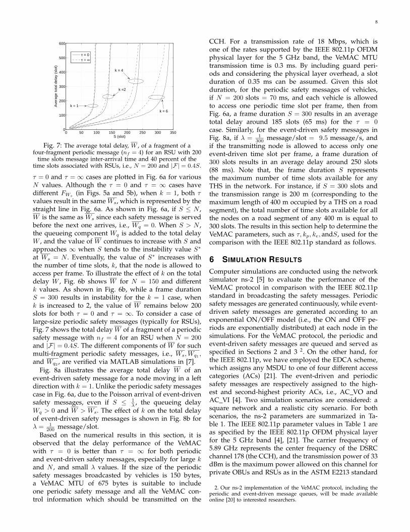
Fig. 8a illustrates the average total delay W of anevent-driven safety message for a node moving in a leftdirection with k = 1. Unlike the periodic safety messagescase in Fig. 6a, due to the Poisson arrival of event-drivensafety messages, even if S ≤ 1
λ , the queueing delayWq > 0 and W > Ws. The effect of k on the total delayof event-driven safety messages is shown in Fig. 8b forλ = 1
200 message/slot.Based on the numerical results in this section, it is
observed that the delay performance of the VeMACwith τ = 0 is better than τ = ∞ for both periodicand event-driven safety messages, especially for large kand N , and small λ values. If the size of the periodicsafety messages broadcasted by vehicles is 150 bytes,a VeMAC MTU of 675 bytes is suitable to includeone periodic safety message and all the VeMAC con-trol information which should be transmitted on the
CCH. For a transmission rate of 18 Mbps, which isone of the rates supported by the IEEE 802.11p OFDMphysical layer for the 5 GHz band, the VeMAC MTUtransmission time is 0.3 ms. By including guard peri-ods and considering the physical layer overhead, a slotduration of 0.35 ms can be assumed. Given this slotduration, for the periodic safety messages of vehicles,if N = 200 slots = 70 ms, and each vehicle is allowedto access one periodic time slot per frame, then fromFig. 6a, a frame duration S = 300 results in an averagetotal delay around 185 slots (65 ms) for the τ = 0case. Similarly, for the event-driven safety messages inFig. 8a, if λ = 1
300 message/slot = 9.5 message/s, andif the transmitting node is allowed to access only oneevent-driven time slot per frame, a frame duration of300 slots results in an average delay around 250 slots(88 ms). Note that, the frame duration S representsthe maximum number of time slots available for anyTHS in the network. For instance, if S = 300 slots andthe transmission range is 200 m (corresponding to themaximum length of 400 m occupied by a THS on a roadsegment), the total number of time slots available for allthe nodes on a road segment of any 400 m is equal to300 slots. The results in this section help to determine theVeMAC parameters, such as τ, kp, ke, andS, used for thecomparison with the IEEE 802.11p standard as follows.
6 SIMULATION RESULTS
Computer simulations are conducted using the networksimulator ns-2 [5] to evaluate the performance of theVeMAC protocol in comparison with the IEEE 802.11pstandard in broadcasting the safety messages. Periodicsafety messages are generated continuously, while event-driven safety messages are generated according to anexponential ON/OFF model (i.e., the ON and OFF pe-riods are exponentially distributed) at each node in thesimulations. For the VeMAC protocol, the periodic andevent-driven safety messages are queued and served asspecified in Sections 2 and 3 2. On the other hand, forthe IEEE 802.11p, we have employed the EDCA scheme,which assigns any MSDU to one of four different accesscategories (ACs) [21]. The event-driven and periodicsafety messages are respectively assigned to the high-est and second-highest priority ACs, i.e., AC VO andAC VI [4]. Two simulation scenarios are considered: asquare network and a realistic city scenario. For bothscenarios, the ns-2 parameters are summarized in Ta-ble 1. The IEEE 802.11p parameter values in Table 1 areas specified by the IEEE 802.11p OFDM physical layerfor the 5 GHz band [4], [21]. The carrier frequency of5.89 GHz represents the center frequency of the DSRCchannel 178 (the CCH), and the transmission power of 33dBm is the maximum power allowed on this channel forprivate OBUs and RSUs as in the ASTM E2213 standard
2. Our ns-2 implementation of the VeMAC protocol, including theperiodic and event-driven message queues, will be made availableonline [20] to interested researchers.

9
0 50 100 150 200 250 300 350 400 4500
100
200
300
400
500
600
S (slot)
Ave
rage
tota
l del
ay (
slot
)
τ = 0τ = ∞
Average service delay
λ = 1/100
λ = 1/200
λ = 1/300
(a) Number of time slots accessedper frame k = 1.
0 100 200 300 400 500 600 700 800 9000
100
200
300
400
500
600
700
800
S (slot)
Ave
rage
tota
l del
ay (
slot
)
τ = 0τ = ∞
k = 4
k = 2
k = 1
(b) Event-driven message average arrivalrate λ = 1
200message/slot.
Fig. 8: The average total delay, W , of an event-driven safety message for a node moving in a left direction with 40 percent ofthe time slots associated with the left direction, i.e., |L| = 0.4S.
TABLE 1: ns-2 simulation parameters
Periodicmessages
Event-driven messages Physical layer
Parameter Value Parameter Value Parameter Value Parameter Value Parameter Value
Size 150bytes Size 450
bytesAverage
OFF time 2 s RXThresh 1.45683×10−09 w CSThresh 8.19468×
10−10 w
Arrivalrate
10 mes-sage/s
AverageON time 1 s
Arrivalrate during
ON time
10 mes-sage/s
Carrierfrequency 5.89 GHz Transmission
power 33 dBm
CPThresh 10 Transmissionrate
12-18Mbps
Antenna Omni-directional
Channelmodel
freespace
Higher layerprotocols
VeMAC IEEE 802.11p
Layer Protocol Parameter Value Parameter Value Parameter Value Parameter ValueTransport
layer UDP S 275slots
Slotduration 0.35 ms aSlotTime 13 µs SIFS 32 µs
Networklayer
dumbagent kp 1 ke 1 AC VO
CW size 3 AC VOAIFS 58 µs
τ 0 MTU 450-675bytes
AC VICW size 7 AC VI
AIFS 71 µs
#bits of anode ID 9 #bits of a
slot index 9 Preamblelength 32 µs
PLCPheaderlength
8 µs
Simulation time: 1 min. for square network and 5 min. for city FCS 4 bytes Headerlength 32 bytes
[22]. Given these values of the carrier frequency and thetransmission power, the receiving threshold (RxThresh)and the carrier sensing threshold (CSThresh) in Table1 result in a communication range of 150 m and acarrier sensing range of 200 m for free space propagation.The capture threshold (CPThresh) is the minimum ratiobetween the powers of two received signals required forthe receiver to capture the signal with the higher powerand discard the one with the lower power. The dumbagent used in the network layer just passes the data fromthe transport layer to the MAC layer while sending, andvice versa while receiving (since all the safety messagesunder consideration are single-hop broadcast messages).
In addition to the total delay (as defined in Sec-tion 4), the following performance metrics are consid-ered: 1) goodput which is the average rate of safetymessages which are successfully delivered to all the
one-hop neighbours; 2) channel utilization defined asthe percentage of time that the channel is used forsuccessful transmission of payload data (a transmissionis considered successful only if it is correctly receivedby all the one-hop neighbours); 3) overhead defined asthe percentage of control information relative to the totalinformation transmitted on the channel; 4) probabilityof a transmission collision, i.e., the probability that atransmitted safety message experiences a collision at oneor more one-hop neighbours; and 5) fairness indicator.A metric is calculated for each node x, denoted by r(x),which is the ratio of the number of safety messages trans-mitted by node x to the total number of safety messagestransmitted by all nodes. The fairness indicator is thedeviation (in percentage) of r(x) from a fair share, f(x),that equals the total number of safety messages generatedat node x normalized by the total number of safety

10
100 150 200 250 300 3500
1
2
3
4
5
6
7
8
9
10
Number of nodes
Go
od
pu
t (m
ess
ag
e/s
ec.
/no
de
)
VeMAC − 12 Mbps
VeMAC − 18 Mbps
802.11p − 12 Mbps
802.11p − 18 Mbps
Periodic
Event−driven
(a) Goodput.
100 150 200 250 300 3500
0.1
0.2
0.3
0.4
0.5
0.6
0.7
Number of nodes
Pro
ba
bili
ty o
f a
tra
nsm
issi
on
co
llisi
on
Periodic − 12 Mbps
Periodic − 18 Mbps
Event−driven − 12 Mbps
Event−driven − 18 Mbps
802.11p
VeMAC
(b) Probability of a transmission collision.
100 150 200 250 300 35010
15
20
25
30
35
40
45
50
55
60
Number of nodes
Channel utilization (percent)
12 Mbps
18 Mbps
VeMAC
802.11p
(c) Channel utilization.
100 150 200 250 300 35010
−4
10−3
10−2
10−1
Number of nodes
To
tal d
ela
y (s
)
Periodic
Event−driven
VeMAC
802.11p
(d) Average delay for a transmission rate of 12 Mbps.
Fig. 9: Simulation results for the square network.
messages generated at all nodes. That is, the fairnessindicator for a node x is equal to | r(x)−f(x)
f(x) | ×100.All the performance metrics, except the overhead andthe channel utilization, are calculated separately for theperiodic and event-driven safety messages.
6.1 Square NetworkThe first scenario under consideration is a set of station-ary nodes uniformly distributed in a square networkwith side length of 500 m. Fig. 9a shows the periodicand event-driven message goodputs of the VeMAC andthe IEEE 802.11p protocols using two different physicallayer transmission rates. Note that, based on the pa-rameters in Table 1, the average rates of periodic andevent-driven safety messages generated at each nodeare 10 messages/s and 3.3 messages/s respectively. Asshown in Fig. 9a, the VeMAC outperforms the IEEE802.11p for all the node densities and transmission ratesunder consideration. For instance, when the number ofnodes in the network is 250, the VeMAC protocol cansuccessfully deliver almost all the periodic and event-driven safety messages to all the one-hop neighbours,while the IEEE 802.11p fails to deliver around 50% ofthe event-driven messages and more than 40% of theperiodic messages using a transmission rate of 12 Mbps.This outperforming of the VeMAC protocol in terms ofsafety message goodput is due to its ability to reduce theprobability of a transmission collision as compared with
the IEEE 802.11p standard. As shown in Fig. 9b, thereis a significant difference between the probability of atransmission collision achieved by the two protocols. Forthe VeMAC protocol, the probability of a transmissioncollision of an event-driven safety packet is higher thanthat of a periodic safety packet, especially at high nodedensities. The reason is that, when the event-drivensafety message queue is empty, a node releases its event-driven time slot (i.e., no information is transmitted inthe slot) and re-acquires a new one when the nextevent-driven safety message is generated. This techniquerelatively increases the rate of access collisions of theevent-driven safety packets, as compared with that of theperiodic ones. Note that, if the periodic safety messagequeue is empty, a node must transmit a Type1 packet(including only control information in this case) in itsperiodic time slot, which allows the node to keep reserv-ing its periodic time slot even when there is no periodicsafety packet waiting for transmission. In Figs. 9a and 9b,the performance of the IEEE 802.11p improves with thehigher transmission rate, since the transmission durationof each packet is reduced, which decreases the proba-bility of a transmission collision from the neighbouringnodes. On the other hand, the effect of the channel rateon the performance of the VeMAC in Figs. 9a and 9bis negligible. As the VeMAC protocol achieves a highermessage goodput than the IEEE 802.11p, it also providesa better channel utilization, as illustrated in Fig. 9c.

11
TABLE 2: VISSIM simulation parameters
Vehicle input Desired speed (Km/h)distribution
Car following(Wiedemann 74)
Lane changing Vehicle characteristics
Parameter Value Location Distribution Parameter Value Parameter Lanechanger
Trailingvehicle Parameter Car Bus
λv1000 vehi-cles/hour
Ringroad U(32, 48) AX 2 m
Maximumdecelera-
tion-4 m/s2 -3 m/s2 Average
length4.44m
11.54m
tw 5 min.All
otherroads
U(55, 72) BXadd 2 m−1m/s2
perdistance
100 m 100 m Width 1.5m
2.5m
tin2, 4, 6,
and 7 min.Rightturns U(12, 18) BXmult 3 m
Accepteddecelera-
tion-1 m/s2 -1 m/s2
Percentageof thetotal #
vehicles
95% 5%
#vehicles
292, 603,839, and
948
Leftturns U(20, 30) Simulation
time: 5 min.
Default VISSIM maximum/desired acceleration and decelera-tion functions for cars and buses as described in [26] have beenused.
Fig. 10: A snap shot of the simulations showing thesimulated roads in blue.
The channel utilization in Fig. 9c improves with thelower transmission rate, due to an increase in the packettransmission duration, which consequently increases thepercentage of time that the channel is used for success-ful transmissions. When the transmission rate decreasesfrom 18 Mbps to 12 Mbps, the channel utilization of theVeMAC protocol increases by a factor of 1.5 (the sameratio between the two transmission rates), while that ofthe IEEE 802.11p increases by a factor less than 1.5, asthe probability of a transmission collision also increaseswith the lower transmission rate.
Fig. 9d shows the total delay of the VeMAC and theIEEE 802.11p protocols. For both periodic and event-driven safety messages, the total delay of the VeMACprotocol is dominated by the access delay component,which is around 48ms (one half the duration of a frame).At the lowest node density in Fig. 9d, the total delay ofthe periodic safety messages for the IEEE 802.11p proto-col is around 280 µs, which is the sum of the durationsof one AC VI AIFS (71 µs), one periodic safety packettransmission duration (164 µs), and the average backofftime ( CW size
2 ×aSlotTime = 45.5 µs). This delay increaseswith the node density, due to an increase in the numberof backoff cycles that a periodic safety packet encounters.The delay of the event-driven safety messages for theIEEE 802.11p protocol is higher than that of the periodicsafety messages, due to a large size of the event-drivenmessages, which results in a higher transmission duration.Although the VeMAC has a higher total delay than the
IEEE 802.11p protocol, it is well below the 100 ms delaybound required for most of the safety applications [9].
6.2 City ScenarioWe consider the city scenario as shown in Fig. 10, whichconsists of a set of roads around the University of Water-loo (UW) campus. To simulate vehicle traffic, the micro-scopic vehicle traffic simulator VISSIM is employed [6].The simulator generates a vehicle trace file, which istransformed to an ns-2 scenario file using a MATLABparser 3. At the start of the simulation, vehicles enterthe road network from every possible entry accordingto a Poisson process with rate λv . After a certain timeduration tin, the vehicle input to the road networkis stopped, and after an additional warm up periodtw (to reduce transient state effects), the position andspeed of each vehicle are recorded at the end of everysimulation step. Two types of vehicles are considered:cars and buses. The two vehicle types differ mainly inthe vehicle dimensions, as well as the maximum/desiredacceleration and deceleration as functions of the vehiclespeed. All cars and buses have the same desired speeddistribution, which differs from one road to another, andduring the left and right turns at intersections. Everyintersection in the road network is controlled either by atraffic light, or a stop sign, based on how the intersectionis controlled in reality. At signalized intersections, leftturns are controlled by the traffic light controller, andright turns are allowed during the red signal phase.Before a vehicle enters an intersection area, it decideswhether to turn left, turn right, or not to make any turn,according to a certain probability mass function, whichdiffers from one intersection to another.
The car following model used is the Wiedemann 74model [23] developed for urban traffic. A vehicle can bein one of four modes: free driving, approaching, follow-ing, and braking. In each mode, the vehicle accelerationis a function of the vehicle speed, the characteristics ofthe driver and the vehicle, as well as the distance and
3. Videos of the VISSIM and ns-2 simulations have been recordedand uploaded to [24] and [25] respectively.

12
292 603 839 9480
1
2
3
4
5
6
7
8
9
10
11
Number of vehicles
Periodic message goodput
(message/s/vehicle)
VeMAC
802.11p
(a) Periodic message goodput.
292 603 839 9480
0.5
1
1.5
2
2.5
3
3.5
Number of vehicles
Eve
nt−
drive
n m
ess
ag
e g
oo
dp
ut
(me
ssa
ge
/s/v
eh
icle
)
VeMAC
802.11p
(b) Event-driven message goodput.
200 400 600 800 100010
−4
10−3
10−2
10−1
100
Number of vehicles
Pro
ba
bili
ty o
f a
tra
nsm
issi
on
co
llisi
on
Periodic
Event−driven
802.11p
VeMAC
(c) Probability of a transmission collision.
292 603 839 9480
5
10
15
20
25
30
35
40
Number of vehicles
Overhead (percent)
VeMAC
802.11p
(d) Overhead.
292 603 839 9480
10
20
30
40
50
60
70
80
Number of vehicles
To
tal d
ela
y (m
s)
Periodic
Event−driven
(e) Average total delay for VeMAC.
0 100 200 300 400 500 600 700 800 900 10000
1
2
3
4
5
6
7
8
9
10
Vehicle index
Periodic message fairness indicator
(percent)
(f) Periodic fairness indicator for VeMAC.
0 100 200 300 400 500 600 700 800 900 10000
1
2
3
4
5
6
7
Vehicle index
Eve
nt−
drive
n m
ess
ag
es
fairn
ess
ind
ica
tor
(pe
rce
nt)
(g) Event-driven fairness indicator for VeMAC.
Fig. 11: Simulation results for the city scenario.
the speed difference between the subject vehicle and thevehicle in front [23]. The last two variables also deter-mine the thresholds between the four driving modes ofa vehicle. The Wiedemann 74 model uses three param-eters: the average standstill distance (AX), the additivepart of the safety distance (BXadd), and the multiplicativepart of the safety distance (BXmult). The AX parameter isthe average desired distance between stationary vehicles,and is used with the BXadd and BXmult parameters todetermine the desired following distance of a vehicle[23]. A vehicle can perform a lane change, either to turnleft or right, or because it has a higher speed than thevehicle in front and there is more space in an adjacentlane. The lane change decision depends on the desiredsafety distance parameters (i.e., BXadd and BXmult), aswell as on the speeds and decelerations of the vehiclemaking the lane change and the vehicle coming frombehind in the destination lane. The VISSIM simulationparameters are summarized in Table 2.
As shown in Figs. 11a and 11b, for all the vehicle
densities under consideration, the VeMAC protocol cansuccessfully deliver almost all the periodic and event-driven safety messages to all the vehicles in the one-hop neighbourhoud. At the highest vehicle density, theVeMAC protocol achieves around 23% and 32% highergoodput respectively in the periodic and event-drivensafety message goodputs, as compared to the IEEE802.11p. Fig. 11c shows the significant difference in theprobability of a transmission collision achieved by thetwo protocols. For instance, when the number of vehiclesis 839, the probability of a collision of a periodic (event-driven) safety message for the IEEE 802.11p is around2 order of magnitude (1.5 order of magnitude) greaterthan for the VeMAC protocol. One main reason of thehigh probability of a transmission collision for the IEEE802.11p is the hidden terminal problem, since for broad-cast packets, no handshaking [request to send/clear tosend (RTS/CTS)] information exchange is used and noacknowledgement is transmitted from any recipient ofthe packet [21]. Another reason is that, although the

13
small CW size assigned to the AC VO and AC VI allowsthe safety packets to be transmitted with small delays,it increases the probability of a transmission collisionwhen multiple vehicles within the same THS are si-multaneously trying to broadcast their safety packets.Further, if a transmission collision of a broadcast packethappens, the CW size is not doubled (such as in theunicast case), as there is no collision detection withoutCTS and acknowledgment packets.
The reduction in the probability of a transmission col-lision by the VeMAC protocol, which results in the highperiodic and event-driven message goodputs in Figs.11a and 11b, is achieved at the expense of an increasein the protocol overhead as shown in Fig. 11d. Themain source of the VeMAC overhead is that every Type1packet transmitted by a certain vehicle x includes the setof one-hop neighbour IDs, N(x), and the time slot indexcorresponding to each node ID in set N(x) (as indicatedin Table 1). On the other hand, the overhead of the IEEE802.11p protocol is due to control information such asthe frame check sequence (FCS) and the physical layerconvergence procedure (PLCP) header. At low vehicledensity, the overheads of the VeMAC protocol and IEEE802.11p are similar, as shown in Fig. 11d. However, whenthe vehicle density increases, the overhead of the IEEE802.11p remains the same, while that of the VeMACprotocol increases due to a large number of one-hopneighbours of each vehicle, which results in a largeamount of control information included in the headerof transmitted Type1 packets. Note that, all the VeMACcontrol information is transmitted on the CCH, which isreserved only for the transmission of safety messagesand control information. As well, the VeMAC controlinformation provides each vehicle with knowledge aboutall the other vehicles in the two-hop neighbourhood.This knowledge can reduce the overhead of some layer 3protocols, such as the elimination of the Hello messagesof position based routing protocols. On the other hand,in a high vehicle density scenario, a large size of theVeMAC control information may increase the number offragments of each periodic safety message broadcastedby an RSU. This excess fragmentation can result inhigher delay of a periodic safety message, unless theRSU accesses more periodic time slots per frame, kp, toserve the periodic safety message queue. The VeMACoverhead can be significantly reduced if each vehiclebroadcasts the set N and the corresponding time slotindices once every m frames, instead of once in everyframe as described in Section 3. However, since the setN and the corresponding time slot indices broadcastedby a certain node are required for the one-hop neigh-bours to detect any transmission collision, as describedin Subsection 3.2, the lack of broadcasting this controlinformation in each frame (i.e., m > 1) may result ina longer time duration for a colliding node to detecta transmission collision, and consequently to resolvethe collision by releasing its time slot and acquiring anew one, a behaviour which can increase the rates of
access collisions and merging collisions. The effect ofthe reduction of the VeMAC overhead when m > 1on the other performance metrics and on the VeMACmultihop broadcast service described in [2] needs furtherinvestigation.
The total delay of the VeMAC protocol for the periodicand event-driven safety messages is shown in Fig. 11e.For both types of safety messages, the VeMAC achievesa total delay that is well below 100 ms. One reason ofthe relative increase in the VeMAC delays at the highestvehicle density is the high contention on the time slotsamong different vehicles which may force a vehicle todelay the transmission of a safety packet until a timeslot is available. To study the fairness of the VeMACprotocol, Figs. 11f and 11g show the fairness indicators ofthe periodic and event-driven messages respectively atthe highest vehicle density under consideration. The pe-riodic (event-driven) message fairness indicator is below0.3% (0.2%) for most of the vehicles, with a maximumvalue of 8.3% (6.2%). These results indicate that, even ina high vehicle density, the VeMAC protocol allows all thevehicles to transmit their safety messages in a fair way.
7 CONCLUSIONS AND FUTURE WORK
This paper focuses on how the VeMAC protocol sup-ports the high priority safety application messages inVANETs and compares its performance with that of theIEEE 802.11p standard. How the periodic and event-driven safety messages are queued and served by theVeMAC protocol has been described, and necessarymodifications to the VeMAC protocol have been definedto allow each node to access multiple time slots perframe on the control channel. A detailed message delayanalysis, including queueing and service delay, has beenpresented for periodic and event-driven safety messages,taking into consideration the size and the arrival patternof the safety messages. Simulation results show thatthe VeMAC protocol can deliver both types of safetymessages to all the nodes in the one-hop neighbouhoudwith an acceptable average delivery delay (less than100 ms). Moreover, it is shown that the VeMAC has alow probability of a transmission collision, which resultsin a higher safety message goodput and better channelutilization, as compared to the IEEE 802.11p standard. Inthe future, we plan to extend the simulations presentedin this paper by considering realistic vehicle traces incity and highway scenarios, to perform hardware im-plementation and real testing of the VeMAC protocol onthe control channel, and to evaluate its performance onthe service channels via analysis and simulations.
ACKNOWLEDGMENTS
We would like to thank Alex Leung (an UndergraduateResearch Assistant) for his help in creating the roadnetwork around the UW campus in VISSIM, and UsamaShahdah (a PhD student in the Transportation SystemsResearch group) for his strong support in using VISSIM.We also would like to thank the reviewers for their

14
comments and suggestions which helped to improve thequality of this paper.
REFERENCES[1] H. A. Omar, W. Zhuang, and L. Li, “VeMAC: a novel multichannel
MAC protocol for vehicular ad hoc networks,” in Proc. IEEEINFOCOM MobiWorld 2011, Apr. 2011, pp. 413–418.
[2] H. A. Omar, W. Zhuang, and L. Li, “VeMAC: A TDMA-basedMAC protocol for reliable broadcast in VANETs,” IEEE Trans.Mobile Comput., 2012 (to appear).
[3] H. A. Omar, W. Zhuang, and L. Li, “Evaluation of VeMAC forV2V and V2R communications under unbalanced vehicle traffic,”in Proc. IEEE VTC2012-Fall, Sep. 2012.
[4] IEEE Std 802.11p-2010, pp. 1–51, Jul. 15, 2010.[5] http://nsnam.isi.edu/nsnam/index.php/Main Page[6] http://vision-traffic.ptvgroup.com/en-uk/products/
ptv-vissim/[7] H. A. Omar, W. Zhuang, and L. Li, “Delay analysis of
VeMAC supporting periodic and event-driven safety messagesin VANETs,” Submitted to IEEE GLOBECOM, Dec. 2013.
[8] R. Baldessari et al., “Car-2-car communication consortium mani-festo,” Tech. Rep. Version 1.1, Aug. 2007.
[9] “Vehicle safety communications project task 3 final report,” TheCAMP Vehicle Safety Communications Consortium, Tech. Rep.DOT HS 809 859, Mar. 2005.
[10] J. Misic, G. Badawy, and V. Misic, “Performance characterizationfor IEEE 802.11p network with single channel devices,” IEEETrans. Veh. Technol., vol. 60, no. 4, pp. 1775–1787, 2011.
[11] S. Ozturk, J. Misic, and V. Misic, “Reaching spatial or networkingsaturation in VANET,” EURASIP J WIREL COMM, pp. 1–12, Nov.2011.
[12] M. Amadeo, C. Campolo, and A. Molinaro, “Enhancing IEEE802.11p/WAVE to provide infotainment applications in VANETs,”Ad Hoc Networks, vol. 10, no. 2, pp. 253–269, Mar. 2012.
[13] “Dedicated short range communications (DSRC) message setdictionary,” SAE J2735 Standard, Nov. 19, 2009.
[14] F. Zaid et al., “Vehicle safety communications-applications (VSC-A) second annual report,” The CAMP Vehicle Safety Communi-cations 2 Consortium, Tech. Rep. DOT HS 811 466, Aug. 2011.
[15] F. Borgonovo, A. Capone, M. Cesana, and L. Fratta, “ADHOCMAC: New MAC architecture for ad hoc networks providing ef-ficient and reliable point-to-point and broadcast services,” WirelessNetworks, vol. 10, pp. 359–366, Jul. 2004.
[16] D. V. Lindley, “The theory of queues with a single server,” MATHPROC CAMBRIDGE, vol. 48, pp. 277–289, 1952.
[17] D. Bertsekas and R. Gallager, Data networks. Upper Saddle River,NJ, USA: Prentice-Hall, Inc., 1987.
[18] L. D. Servi, “D/G/1 queues with vacations,” OPER RES, vol. 34,no. 4, pp. 619–629, 1986.
[19] W. Song and W. Zhuang, “Performance analysis of probabilisticmultipath transmission of video streaming traffic over multi-radiowireless devices,” IEEE Trans. Wireless Commun., vol. 11, no. 4, pp.1554 –1564, Apr. 2012.
[20] https://code.google.com/p/vemac/[21] IEEE Std 802.11-2007 (Revision of IEEE Std 802.11-1999), pp. 1–1184,
Jun. 2007.[22] ASTM Standard E2213, 2003 (2010).[23] R. Wiedemann, “Modeling of RTI-Elements on multi-lane roads,”
in Advanced Telematics in Road Transport, Proc. the Drive Conference,Feb. 1991.
[24] http://youtu.be/48daRU6ZpjI[25] http://youtu.be/GjYWe7eLJ3s[26] PTV Planung Transport Verkehr AG, VISSIM 5.40-User Manual,
2012.
Hassan Aboubakr Omar (S’11) received theM.Sc. (2009) degree in Engineering Mathemat-ics and the B.Sc. degree (2005) in Electron-ics and Communications Engineering, both fromCairo University, Egypt. From 2005 to 2008, hewas a Research Assistant at the Science andTechnology Research Center, at the AmericanUniversity in Cairo. Since 2010, he has beenworking toward a Ph.D. degree at the Depart-ment of Electrical and Computer Engineering,University of Waterloo, Canada. Mr. Omar’s cur-
rent research interest includes medium access control, routing, and roadside unit placement in vehicular ad hoc networks.
Weihua Zhuang (M’93-SM’01-F’08) has beenwith the Department of Electrical and ComputerEngineering, University of Waterloo, Canada,since 1993, where she is a Professor and a Tier ICanada Research Chair in Wireless Communi-cation Networks. Her current research focuseson resource allocation and QoS provisioning inwireless networks. She is a co-recipient of theBest Paper Awards from the IEEE MultimediaCommunications Technical Committee in 2011,IEEE Vehicular Technology Conference (VTC)
Fall 2010, IEEE Wireless Communications and Networking Conference(WCNC) 2007 and 2010, IEEE International Conference on Communi-cations (ICC) 2007, and the International Conference on HeterogeneousNetworking for Quality, Reliability, Security and Robustness (QShine)2007 and 2008. She received the Outstanding Performance Award 4times since 2005 from the University of Waterloo, and the Premier’sResearch Excellence Award in 2001 from the Ontario Government.Dr. Zhuang is the Editor-in-Chief of IEEE Transactions on VehicularTechnology, and the Technical Program Symposia Chair of the IEEEGlobecom 2011. She is a Fellow of the IEEE, a Fellow of the CanadianAcademy of Engineering (CAE), a Fellow of the Engineering Institute ofCanada (EIC), and an elected member in the Board of Governors of theIEEE Vehicular Technology Society. She was an IEEE CommunicationsSociety Distinguished Lecturer (2008-2011).
Atef Abdrabou (M’09) received the Ph.D. de-gree in Electrical Engineering from the Uni-versity of Waterloo, Waterloo, ON, Canada, in2008. In 2010, he joined the Department ofElectrical Engineering, United Arab EmiratesUniversity, Al-Ain, Abu Dhabi, UAE, where heis an Assistant Professor. His research inter-ests include smart grid communication, networkresource management, quality-of-service provi-sioning, and information dissemination in self-organizing wireless networks. Dr. Abdrabou is
a co-recipient of a Best Paper Award of IEEE WCNC 2010. In 2009,he received the National Science and Engineering Research Councilof Canada (NSERC) postdoctoral fellowship for academic excellence,research potential, communication, and leadership abilities. He is anAssociate Editor of the Journal of Circuits, Systems, and Computers.
Li Li (M’03) received the M.Sc. (1990) degreein Electrical Engineering from Southeast Uni-versity, Nanjing, China and Ph.D (1993) degreein Electrical Engineering from University of Ot-tawa, Ottawa, ON, Canada. From 1993 to 1999,she was with Nortel Networks Ltd. as a sys-tem architect and then product manager. From1999 to 2003, she was the chief architecture atSS8 Networks Inc. Since 2003, she has beenwith Communications Research Centre (CRC),Ottawa, ON, Canada, where she is a research
scientist. She has contributed previously to ITU-T and IETF standardworking groups, co-authored IETF RFC and has been awarded withseveral US patents. Her current research focuses on mobile tacticalradio networking and adaptive networks, with particular interests inmobile network optimization, networking protocols and algorithms, andperformance modeling of mobile networks. She has served as anAssociated Editor for Springer’s Journal on Peer-to-peer Networkingand Applications. Dr. Li has served as Co-chair for the IEEE PERCOMMP2P’06-08 workshops, track co-chair for IEEE VTC2010-Fall, andsession co-chair for IEEE MILCOM’08-11, and track co-chair for IEEEMILCOM 2012. She is an Associate Editor for IEEE Transactions onVehicular Technology.