Embed Size (px)
Citation preview

MEE09:50
PERFORMANCE EVALUATION OF MPLS/GMPLS CONTROL PLANE
SIGNALING PROTOCOLS
Ngugi Lawrence Chege
Bwalya Freelance
This thesis is presented as part of Degree of Master of Science in Electrical Engineering
Blekinge Institute of Technology
August 2009
Blekinge Institute of Technology School of Computing Supervisor: Dr. Doru Constantinescu Examiner: Dr. Doru Constantinescu

MEE09:50
ii

MEE09:50
iii
ABSTRACT
Multi-Protocol Label Switching (MPLS) emerged as a suitable solution to optimization of Internet Protocol (IP) networks. It improves network efficiency, utilization of resources and resilience in packet switched networks. With MPLS, packet forwarding decisions are made based on label inspection rather than packet header information.
While MPLS is native to packet switched networks, Generalized Multiprotocol Label Switching (GMPLS) extends MPLS functionality to networks that support non-packet switched domains such as time, lambda and fiber. GMPLS also offers better resource management through the use of a new protocol; Link Management Protocol (LMP).
In this work, a performance evaluation of GMPLS and MPLS control plane signaling protocols was performed. Further, a control plane interworking model for MPLS and GMPLS networks was proposed.
Simulations were carried out to examine the performance of signaling protocols in an MPLS network configured with, and without Quality-of-Service (QoS). Conclusions on the performance characteristics of each signaling protocol were made based on the collected results.

MEE09:50
iv

MEE09:50
v
ACKNOWLEDGEMENTS
To my wife Racheal and our children, Chomba and Chisela. You braved a difficult time without me because you believed in what I was pursuing in Sweden. Your perseverance was not in vain and I thank you with all my heart. I also thank my other family members, friends and my employer Zamtel who helped immensely during my time of absence. This has been a success only because of you.
-Bwalya Freelance-
I would like to express my heartfelt gratitude to my parents, Mr. and Mrs. Ngugi and siblings Ann and Paul. Your prayers and encouragement have always helped me overcome the most daunting challenges.
-Lawrence Ngugi-
We recognize with delight the support and guidance that our thesis supervisor, Dr. Doru Constantinescu, offered during the course of the project. We have gained so much knowledge because people like you, in and around BTH made sure it happened.
We thank OPNET for giving us six months licenses for OPNET Modeler, Wireless Module, Flow Analysis Module and MPLS Specialized Module.
-Freelance and Lawrence-

MEE09:50
vi
MEE09:50
vii
TABLE OF CONTENTS
ABSTRACT ----------------------------------------------------------------------------------------------------------------------- iii
ACKNOWLEDGEMENTS ------------------------------------------------------------------------------------------------------- v
TABLE OF CONTENTS -------------------------------------------------------------------------------------------------------- vii
LIST OF FIGURES --------------------------------------------------------------------------------------------------------------- xi
LIST OF TABLES ---------------------------------------------------------------------------------------------------------------- xiii
ACRONYMS--------------------------------------------------------------------------------------------------------------------- xv
1 INTRODUCTION ---------------------------------------------------------------------------------------------------------- 1
1.1 THESIS MOTIVATION --------------------------------------------------------------------------------------------- 1
1.2 THESIS OUTLINE --------------------------------------------------------------------------------------------------- 2
1.3 RELATED WORK ---------------------------------------------------------------------------------------------------- 2
2 MPLS OVERVIEW --------------------------------------------------------------------------------------------------------- 5
2.1 MPLS LABELS ------------------------------------------------------------------------------------------------------- 6
2.1.1 LABEL ENCAPSULATION ----------------------------------------------------------------------------------- 6
2.1.2 LABEL VALUE ASSIGNMENT ------------------------------------------------------------------------------ 7
2.2 FORWARDING EQUIVALENCE CLASS -------------------------------------------------------------------------- 7
2.3 LABEL ASSIGNMENT AND DISTRIBUTION -------------------------------------------------------------------- 7
2.4 LABEL SWITCHED PATHS ----------------------------------------------------------------------------------------- 8
2.5 MPLS DATA AND CONTROL PLANES -------------------------------------------------------------------------- 9
2.5.1 MPLS DATA PLANE------------------------------------------------------------------------------------------ 9
2.5.2 MPLS CONTROL PLANE ---------------------------------------------------------------------------------- 10
2.6 LABEL DISTRIBUTION PROTOCOL ---------------------------------------------------------------------------- 11
2.6.1 LDP MESSAGE EXCHANGE ------------------------------------------------------------------------------ 11
2.6.2 LDP PDUs AND PROCEDURES -------------------------------------------------------------------------- 11
2.7 CONSTRAINT ROUTING-LABEL DISTRIBUTION PROTOCOL -------------------------------------------- 12
2.7.1 CR-LDP PROTOCOL SPECIFICATION ------------------------------------------------------------------- 12
2.8 RESOURCE RESERVATION PROTOCOL-TRAFFIC ENGINEERING --------------------------------------- 13
2.8.1 RESERVATION STYLES ------------------------------------------------------------------------------------ 13
2.8.2 RSVP-TE MESSAGES -------------------------------------------------------------------------------------- 14
3 GMPLS OVERVIEW ----------------------------------------------------------------------------------------------------- 15
3.1 G-LABEL ------------------------------------------------------------------------------------------------------------ 16

MEE09:50
viii
3.2 LABEL DISTRIBUTION ------------------------------------------------------------------------------------------- 16
3.2.1 LABEL RESTRICTION BY UPSTREAM ------------------------------------------------------------------ 16
3.3 GMPLS CONTROL PLANE--------------------------------------------------------------------------------------- 16
3.3.1 GMPLS SIGNALING PROTOCOLS ----------------------------------------------------------------------- 17
3.3.2 GMPLS ROUTING PROTOCOLS ------------------------------------------------------------------------- 17
3.4 LINK MANAGEMENT PROTOCOL ---------------------------------------------------------------------------- 17
4 MPLS SUPPORT FOR DIFFSERV ------------------------------------------------------------------------------------- 19
4.1 COMBINED IMPLEMENTATION OVERVIEW --------------------------------------------------------------- 19
4.1.1 EXPEDITED FORWARDING ------------------------------------------------------------------------------ 19
4.1.2 ASSURED FORWARDING -------------------------------------------------------------------------------- 19
4.2 MPLS ADAPTATION OF FORWARDING PHBs-------------------------------------------------------------- 20
5 INTERWORKING OF MPLS AND GMPLS --------------------------------------------------------------------------- 21
5.1 IETF INTERWORKING REQUIREMENTS --------------------------------------------------------------------- 21
5.2 INTERWORKING MODELS ------------------------------------------------------------------------------------- 21
5.3 INTERWORKING PROPOSAL----------------------------------------------------------------------------------- 22
5.3.1 ISLAND MPLS NODES ------------------------------------------------------------------------------------ 23
5.3.2 EDGE NODES ----------------------------------------------------------------------------------------------- 23
5.3.3 USER-NETWORK INTERFACE --------------------------------------------------------------------------- 23
5.3.4 CORE NODES ----------------------------------------------------------------------------------------------- 24
5.3.5 SIGNALING IN INTERWORKING MODEL ------------------------------------------------------------- 24
6 PERFORMANCE METRICS -------------------------------------------------------------------------------------------- 27
6.1 LSP PACKET DELAY ---------------------------------------------------------------------------------------------- 27
6.2 LSP TRAFFIC IN --------------------------------------------------------------------------------------------------- 27
6.3 QUEUING DELAY ------------------------------------------------------------------------------------------------- 27
6.4 THROUGHPUT ---------------------------------------------------------------------------------------------------- 27
7 SIMULATION TOOLS --------------------------------------------------------------------------------------------------- 29
7.1 OMNet++ ---------------------------------------------------------------------------------------------------------- 29
7.2 NS2 ------------------------------------------------------------------------------------------------------------------ 29
7.3 OPNET MODELER ------------------------------------------------------------------------------------------------ 29
7.4 GMPLS LIGHTWAVE AGILE SWITCHING SIMULATOR --------------------------------------------------- 30
8 SIMULATIONS ----------------------------------------------------------------------------------------------------------- 31
8.1 CONFIGURED APPLICATIONS --------------------------------------------------------------------------------- 32

MEE09:50
ix
8.2 CONFIGURED PROFILES ---------------------------------------------------------------------------------------- 33
8.3 CONFIGURED FECs AND LSPs --------------------------------------------------------------------------------- 33
8.4 CONFIGURED TRAFFIC TRUNKS ------------------------------------------------------------------------------ 33
8.5 TRAFFIC MAPPING CONFIGURATION ----------------------------------------------------------------------- 33
8.6 PROJECT SCENARIOS AND RESULTS ------------------------------------------------------------------------- 33
8.6.1 RSVPTE_ERLSP_LOOSE AND CRLDP_ERLSP_LOOSE SCENARIOS WITH NO QoS ----------- 34
8.6.2 RSVPTE_ERLSP_LOOSE AND CRLDP_ERLSP_LOOSE SCENARIOS WITH QoS ---------------- 38
9 CONCLUSION ------------------------------------------------------------------------------------------------------------ 45
10 FUTURE WORK ------------------------------------------------------------------------------------------------------ 47
APPENDIX A -------------------------------------------------------------------------------------------------------------------- 49
REFERENCES ------------------------------------------------------------------------------------------------------------------- 51

MEE09:50
x

MEE09:50
xi
LIST OF FIGURES
Figure 1. Typical MPLS Network ............................................................................................................ 5 Figure 2. MPLS Label Structure ............................................................................................................. 6 Figure 3. MPLS Label Assignment Procedure ......................................................................................... 8 Figure 4. Separation of Control Plane and Data Plane in MPLS .............................................................. 9 Figure 5. MPLS Control Plane Protocol Stack ....................................................................................... 10 Figure 6. LDP PDU Structure ............................................................................................................... 11 Figure 7. GMPLS Protocol Stack .......................................................................................................... 15 Figure 8. Forwarding PHBs and respective DS field bit assignments .................................................... 20 Figure 9. MPLS/GMPLS Interworking Reference Model ....................................................................... 22 Figure 10. Logical Configuration of Edge Node .................................................................................... 23 Figure 11. Signaling for End-to-End LSP setup ..................................................................................... 24 Figure 12. Simulation Network Diagram ............................................................................................. 31 Figure 13. CR-LDP and RSVP-TE LSP Packet Delay for Soft_center <-> Grasvik_BTH LSP ....................... 35 Figure 14. CR-LDP and RSVP-TE LSP Packet Delay for Ronneby_Lib <-> Grasvik_BTH LSP ..................... 35 Figure 15. CR-LDP and RSVP-TE LSP Traffic In for Soft_center <-> Grasvik_BTH LSP ............................. 36 Figure 16. CR-LDP and RSVP-TE LSP Traffic In for Ronneby_Lib <-> Grasvik_BTH LSP ........................... 37 Figure 17. Grasvik_BTH -> Grasvik_Lib Link Throughput ...................................................................... 38 Figure 18. CR-LDP and RSVP-TE LSP Packet Delay for Soft_center <-> Grasvik_BTH LSP with QoS ..... 40 Figure 19. CR-LDP and RSVP-TE LSP Packet Delay for Ronneby_Lib <-> Grasvik_BTH LSP with QoS ...... 40 Figure 20. CR-LDP and RSVP-TE LSP Traffic In for Soft_center <-> Grasvik_BTH LSP with QoS .............. 41 Figure 21. CR-LDP and RSVP-TE LSP Traffic In for Ronneby_Lib <-> Grasvik_BTH LSP with QoS ............ 42 Figure 22. Grasvik_BTH -> Grasvik_Lib Link Throughput ...................................................................... 43 Figure 23. Grasvik_BTH -> Grasvik_Lib Link Queuing Delay (With and Without QoS) ........................... 44

MEE09:50
xii

MEE09:50
xiii
LIST OF TABLES
Table 1. MPLS Label Value Assignment ----------------------------------------------------------------------------------- 7 Table 2. Summary Description of Constraint TLVs ------------------------------------------------------------------- 13 Table 3. New RSVP-TE Message Objects -------------------------------------------------------------------------------- 14 Table 4. Selected Applications and Examples of Their Uses ------------------------------------------------------- 32

MEE09:50
xiv

MEE09:50
xv
ACRONYMS
ATM Asynchronous Transfer Mode BA Behavior Aggregate BGP Border Gateway Protocol CR-LDP Constraint-Routed Label Distribution Protocol DSCP Differentiated Services Code Point EIA Emulation-based Interworking Architecture ER-LSP Explicitely Routed Label Switched Path ER-TLV Explicitely Routed Type Length Value FEC Forwarding Equivalence Class GLASS GMPLS Lightwave Agile Switching Simulator GMPLS Generalized Multiprotocol Label Switching GPID Generalized Payload Identifier GRE Generic Routing Encapsulation IETF Internet Engineering TaskForce IGP Interior Gateway Protocol IP Internet Protocol IPSec IP Security IS-IS Intermediate System-to- Intermediate System IS-IS-TE Intermediate System-to- Intermediate System Traffic Engineering LDP Label Distribution Protocol LER Label Edge Router LIB Label Information Base LMP Link Management Protocol LSP Label Switched Path LSR Label Switched Router MPLS Multiprotocol Label Switching MTU Maximum Transmission Unit NG-SDH Next Generation Synchronous Digital Hierarchy NNI Network-to-Network Interface OSPF Open Shorted Path First OSPF-TE Open Shorted Path First Traffic Engineering OXC Optical Cross Connect PDU Protocol Data Unit PHB Per Hop Behavior QoS Quality-of-Service RSVP Resource Reservation Protocol RSVP-TE Resource Reservation Protocol Traffic Engineering SONET Synchronous Optical Network SSFNet Scalable Simulation Framework + Network Models TCP Transmission Control Protocol TED Traffic Engineering Database TLV Type Length Value TTL Time To Live UDP User Datagram Protocol UNI User-to-Network Interface WFQ Weighted Fair Queuing
MEE09:50
1
1 INTRODUCTION Following challenges faced by conventional IP networks to meet present-day demands on speed, traffic engineering, QoS and scalability, MPLS has emerged as a suitable solution to optimization of future IP networks. MPLS is geared towards improving flexibility and scalability of routing at network layer. Furthermore, it increases network performance and efficiency. Currently, MPLS has been adopted in major IP carrier networks. GMPLS extends the functionality of MPLS to cover not only packet-switched networks but also fiber, wavelength and time switched networks.
Unlike conversional routing were data and control planes are integrated, MPLS/GMPLS separates the two planes and streamlines their functions. While the forwarding plane’s responsibility is to move packets from the ingress port of an MPLS-enabled switch to its egress port, the control plane provides the means to dynamically construct Label Switched Paths (LSP) for efficient data transport across a network.
The MPLS/GMPLS control plane is comprised of two components; signaling protocols and routing protocols. Routing protocols are responsible for gathering and maintaining network topology information used by routers to compute network routes. Signaling protocols are responsible for carrying out connection management functions such as establishment, maintenance, and tear-down of LSPs.
In this work, we carry out a detailed assessment of the implementations of the different MPLS control plane signaling protocols and evaluate how each impact on the QoS for different traffic types. In addition, a solution for interworking of MPLS enabled IP networks and GMPLS enabled legacy networks (e.g. SONET, NG‐SDH) with respect to end-to-end Explicit Routed Label Switched Paths (ER-LSP) setup is proposed.
1.1 THESIS MOTIVATION In MPLS, a Label Switched Path (LSP) between two peering Label Edge Routers (LER) must be constructed before data transmission can commence. An LSP can either be configured as static or dynamic. While a static LSP requires manual configuration on each node along its path, a dynamic LSP requires a signaling protocol for distribution of labels and management of connections. An MPLS domain can only be configured with one signaling protocol. Label Distribution Protocol (LDP), Resource Reservation Protocol/Traffic Engineering (RSVP-TE) and Constraint Routed LDP (CR-LDP) are three signaling protocols defined for MPLS.
Each signaling protocol has unique characteristics that influence the overall performance of an MPLS network. There is need to evaluate performance of each signaling protocol under different network conditions. From such evaluation, it is possible to determine which signaling protocol gives the best performance for different MPLS networks.

MEE09:50
2
The GMPLS control plane differs from that of MPLS. There is often need for MPLS and GMPLS networks to co-exist at a certain migration stage. With different control plane architectures, it is not possible to realize end-to-end LSPs between two island MPLS networks interconnected by a GMPLS network. There is need for a design that makes it possible to establish end-to-end ER-LSPs across both MPLS and GMPLS domains.
1.2 THESIS OUTLINE The work done in this thesis is presented in ten chapters. In Chapter 1, the concepts of MPLS and GMPLS are introduced. In particular, the control plane composition is presented. Detailed literature review of MPLS and GMPLS are discussed in Chapters 2 and 3 respectively. Chapter 4 covers support for Differentiated Services (DiffServ) detailing adaptation of forwarding Per-Hop-Behavior (PHB) to MPLS. An interworking model for MPLS and GMPLS is proposed in Chapter 5. Performance metrics and simulation tools relevant to this thesis are discussed in Chapters 6 and 7 respectively. Chapter 8 describes the OPNET simulation configuration for different scenarios and shows the obtained results. Further, an analysis and explanation of the results is also presented here. Finally, conclusions drawn from analyzed results and some thoughts for future work are presented in Chapters 9 and 10 respectively.
1.3 RELATED WORK To gain greater insight into what would be required to achieve the objectives set, an evaluation of work carried out by other authors and which closely relates to the objectives of this thesis, was carried out. Four papers in particular were considered.
In [10], the authors set out to accomplish the following objective; to outline the motivation behind successful development and deployment of MPLS, to bring out the core values of MPLS and to compare the MPLS protocols.
A summary of the main signaling protocols including CR-LDP, LDP and RSVP-TE was given. In addition, a theoretical comparison of signaling protocols based on referenced material was presented. The paper also discusses traffic engineering in MPLS.
Simulation of an MPLS network focusing towards the comparison of CR-LDP and RSVP-TE based on the LSP set up time, delay and throughput was conducted. OPNET modeler 8.1 was used as simulation tool. The authors concluded that “Almost similar functionality has been accomplished in the establishment of traffic-engineered paths, using both protocols”.
In [16], the objective was to propose a possible solution for interworking of GMPLS enabled networks and IP/MPLS networks.
The paper identified the current problem of interworking between IP + MPLS and GMPLS for a unified application of traffic engineering. The problem is that MPLS and GMPLS control planes and protocol suites differ extensively making it impossible to realize seamless traffic engineering.

MEE09:50
3
A peer model in which “all nodes are controlled by one control plane (C-plane)” and overlay model in which “two networks are controlled by different C-planes”, were identified as the best approaches to solve this problem.
The paper proposed “an interworking architecture between GMPLS and IP + MPLS called Emulation-based Interworking Architecture (EIA) based on extended routing and signaling”.
The authors simulated their solution by forwarding packets from an MPLS LSP through a packet switched capable (PSC) and a lambda switched capable (LSC) GMPLS RSVP-TE LSP terminated on another MPLS LSP across the GMPLS network. The paper did not indicate the simulation tool used. However, close inspection points to proprietary active equipment.
The results showed captured packet data as it crossed the GMPLS network. Indeed, three labels were shown to be attached to the packet indicating lambda label, packet label and MPLS label. It showed that using the EIA method, acceptable results could be achieved.
In [17], the authors set out to compare performance of IP + MPLS networks to IP over ATM networks. They categorized traffic into best effort, high priority and further two types of real time traffic.
Using the NS2 network simulator data was modeled such that the total bandwidth requirement of the aggregated flows did not exceed the bandwidth of any single link. Consequently, congestion could only arise due to processing delays on the routers providing thus a means to compare router switching efficiency in the two scenarios. Furthermore, route reconfiguration ability of MPLS when a link fails, was simulated.
MPLS was seen to optimize a higher proportion of bandwidth usage compared to IP over ATM.
In [18], a comparison between conventional IP and MPLS enabled networks was conducted. The goal was to investigate the impact of traffic engineering on the traditional network.
The simulator used was NS2. Constant bit rate (CBR) Voice over Internet Protocol (VOIP) was used to simulate real-time traffic. Real time traffic header compression was not implemented. Only UDP traffic was considered and tail drop was used as congestion control mechanism.
The authors observed that, traffic engineering improved network throughput. A three-fold reduction in packet drop rate was also noted.

MEE09:50
4

MEE09:50
5
2 MPLS OVERVIEW In conversional IP forwarding, each router makes an independent forwarding decision for each packet based on the IP header routing information. This requires the router to carry out an in-depth analysis of the packet’s header and check the routing table to make a decision on the packet’s next hop [1].
Advancements in hardware and software have increased router throughput in packet switched networks. Nonetheless, flexibility in packet forwarding, minimized packet processing time and adaptation of packet forwarding to mechanisms which aim at enhanced network efficiency and QoS such as traffic engineering, are often required.
MPLS was designed to meet the above requirements. In MPLS, the forwarding of packets is done based on a short fixed value known as a “label”, inserted into a packet. All packets are labeled before being forwarded and consequently, at down-stream routers, analysis of the packet’s network layer header is not required [1]. Rather, decisions on where to forward packets are made by using the inserted label. Furthermore, MPLS offers the following advantages [3]:
Enhanced network layer routing scalability. Provision of routing flexibility. Increased network performance. Simplified integrations of equipment using non-IP forwarding paradigms.
An MPLS domain is comprised of MPLS-enabled routers typically interconnected in a meshed topology as shown in Figure 1.
Figure 1. Typical MPLS Network
MEE09:50
6
The LER is deployed at the perimeter of an MPLS network and performs the basic role of inserting and removing labels when it acts as an ingress or egress router respectively. It also performs label binding by mapping a unique label to each Forwarding Equivalence Class (FEC). A Label Switched Router (LSR) is a router capable of making forwarding decisions using an attached MPLS label and a label forwarding table.
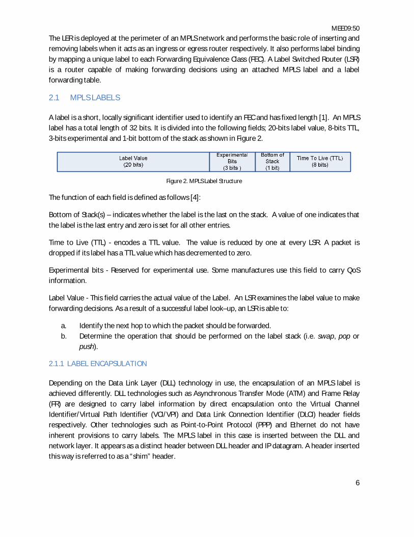
2.1 MPLS LABELS A label is a short, locally significant identifier used to identify an FEC and has fixed length [1]. An MPLS label has a total length of 32 bits. It is divided into the following fields; 20-bits label value, 8-bits TTL, 3-bits experimental and 1-bit bottom of the stack as shown in Figure 2.
Figure 2. MPLS Label Structure
The function of each field is defined as follows [4]:
Bottom of Stack(s) – indicates whether the label is the last on the stack. A value of one indicates that the label is the last entry and zero is set for all other entries.
Time to Live (TTL) - encodes a TTL value. The value is reduced by one at every LSR. A packet is dropped if its label has a TTL value which has decremented to zero.
Experimental bits - Reserved for experimental use. Some manufactures use this field to carry QoS information.
Label Value - This field carries the actual value of the Label. An LSR examines the label value to make forwarding decisions. As a result of a successful label look–up, an LSR is able to:
a. Identify the next hop to which the packet should be forwarded. b. Determine the operation that should be performed on the label stack (i.e. swap, pop or
push).
2.1.1 LABEL ENCAPSULATION Depending on the Data Link Layer (DLL) technology in use, the encapsulation of an MPLS label is achieved differently. DLL technologies such as Asynchronous Transfer Mode (ATM) and Frame Relay (FR) are designed to carry label information by direct encapsulation onto the Virtual Channel Identifier/Virtual Path Identifier (VCI/VPI) and Data Link Connection Identifier (DLCI) header fields respectively. Other technologies such as Point-to-Point Protocol (PPP) and Ethernet do not have inherent provisions to carry labels. The MPLS label in this case is inserted between the DLL and network layer. It appears as a distinct header between DLL header and IP datagram. A header inserted this way is referred to as a “shim” header.

MEE09:50
7
2.1.2 LABEL VALUE ASSIGNMENT Some label values have been reserved for communicating specific information and cannot be allocated by an LSR. Table 1 shows the allocation of valid label values in MPLS [4].
Label Value Assignment Notes 0 IPv4 Explicit NULL
Label Only valid at bottom of the stack. Indicates that the label should be popped and forwarding should be done using IPv4 header
1 Router Alert Label Valid anywhere except at the bottom. Packet is delivered to a local processing module
2 IPv6 Explicit NULL Label
Only valid when the label is a last entry. Indicates that the label should be popped and forwarding should be done using IPv6 header
3 Implicit NULL Label This label can be assigned or distributed by an LSR, but it never actually appears in the encapsulation
4-15 Reserved Reserved 16 Upwards Available Available for assignment by an LSR
Table 1. MPLS Label Value Assignment
2.2 FORWARDING EQUIVALENCE CLASS An FEC is a group of packets sharing the same label forwarding criteria and are consequently treated the same by an LSR. A label is attached to a packet to correspond to one of the following parameters; destination or source IP address range, source or destination port, egress router outgoing interface, QoS, or protocol.
In MPLS FEC, packet assignment is performed only once at the ingress LER [1]. A table that specifies how packets belonging to each FEC should be forwarded is built by each LSR [6]. The table is referred to as Label Information Base (LIB) and its role is to maintain FEC-to-label bindings.
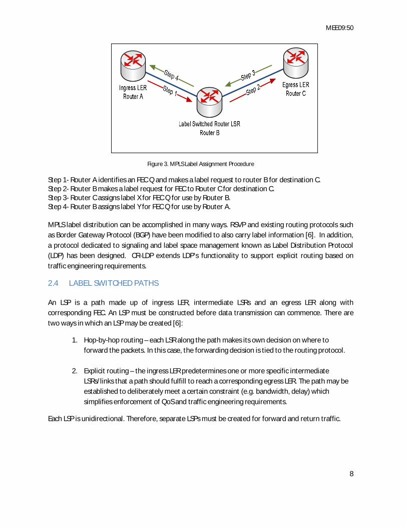
2.3 LABEL ASSIGNMENT AND DISTRIBUTION The process of label assignment can be separated into two distinct operations, namely; label request and label mapping. In label requests, the upstream router makes a request to its downstream neighbor to bind a specific FEC [6]. In response, the downstream LSR sends a label to the upstream LSR using label mapping process. It thus can be seen that labels are downstream assigned and label bindings distribution is done in the downstream to upstream direction [1]. The process of label assignment is depicted in Figure 3 below:
MEE09:50
8
Figure 3. MPLS Label Assignment Procedure
Step 1- Router A identifies an FEC Q and makes a label request to router B for destination C. Step 2- Router B makes a label request for FEC to Router C for destination C. Step 3- Router C assigns label X for FEC Q for use by Router B. Step 4- Router B assigns label Y for FEC Q for use by Router A.
MPLS label distribution can be accomplished in many ways. RSVP and existing routing protocols such as Border Gateway Protocol (BGP) have been modified to also carry label information [6]. In addition, a protocol dedicated to signaling and label space management known as Label Distribution Protocol (LDP) has been designed. CR-LDP extends LDP’s functionality to support explicit routing based on traffic engineering requirements.
2.4 LABEL SWITCHED PATHS An LSP is a path made up of ingress LER, intermediate LSRs and an egress LER along with corresponding FEC. An LSP must be constructed before data transmission can commence. There are two ways in which an LSP may be created [6]:
1. Hop-by-hop routing – each LSR along the path makes its own decision on where to forward the packets. In this case, the forwarding decision is tied to the routing protocol.
2. Explicit routing – the ingress LER predetermines one or more specific intermediate LSRs/links that a path should fulfill to reach a corresponding egress LER. The path may be established to deliberately meet a certain constraint (e.g. bandwidth, delay) which simplifies enforcement of QoS and traffic engineering requirements.
Each LSP is unidirectional. Therefore, separate LSPs must be created for forward and return traffic.
MEE09:50
9
2.5 MPLS DATA AND CONTROL PLANES Conventional routing employs a unified control and data plane. Data forwarding is based on longest prefix match in destination-based forwarding [7]. This approach requires high processing effort which proves to be time-consuming for routers. MPLS separates the network layer routing function into two components: the data/forwarding plane and the control plane. Figure 4 below illustrates the distinction between data plane and control plane.
Figure 4. Separation of Control Plane and Data Plane in MPLS
2.5.1 MPLS DATA PLANE The forwarding plane is responsible for moving packets from input to output on an LSR using the information contained in the forwarding table and the packet itself [7].
Once the LER groups packets into FECs with unique labels, an LSR needs not look up the IP packet header for making a forwarding decision [3]. It only inspects the label and crosschecks it with the label forwarding table. Before forwarding the packet, the LSR may swap the old label with one that indicates the FEC for the next-hop router.

MEE09:50
10
2.5.2 MPLS CONTROL PLANE The control plane provides the means to dynamically set up LSPs for efficient data transport across a data packet network [3]. It is required for automatic set up and tear-down of LSPs. The two components that make up the MPLS control plane are; routing protocols and signaling protocols. The diagram in Figure 5 below shows the protocol stack for the MPLS control plane.
Figure 5. MPLS Control Plane Protocol Stack
2.5.2.1 ROUTING PROTOCOLS MPLS uses standard routing protocols such as Open Shortest Path First (OSPF), Intermediate System-Intermediate System (IS-IS), and BGP to gather network topology information. The topology information is then used by LSRs and LERs to calculate routes across an MPLS network [3].
In order to facilitate traffic engineered LSPs, the Internet Engineering Task Force (IETF) extended the OSPF and IS-IS routing protocols [3]. The enhanced protocols, ISIS-TE and OSPF-TE, include extensions to allow for traffic engineering. OSPF-TE and ISIS-TE create a database called Traffic Engineering Database (TED) into which topology information is stored.

MEE09:50
11
2.5.2.2 MPLS SIGNALING PROTOCOLS The responsibilities of distributing label bindings between LSRs and connection management are carried out by signaling protocols [3, 7]. In addition, signaling protocols facilitate the provisioning of advanced features such as LSP explicit routing, resource reservation and loop prevention.
LDP, CR-LDP and Resource RSVP-TE are three IETF proposed label distribution protocols [7, 8].
2.6 LABEL DISTRIBUTION PROTOCOL LDP is comprised of messages and procedures used by LSRs to establish LSPs in an MPLS network [8]. LSRs achieve this by mapping conventional network layer routing information to data link layer switched paths.
An LDP session is created for each label space. Transport Control Protocol (TCP) is used as the transport layer protocol for LDP sessions. When multiple LDP sessions need to be set up between two LSRs, each LDP session requires one TCP session. However, in the discovery phase (i.e. exchange of HELLO messages) LDP uses User Datagram Protocol (UDP) [6].
2.6.1 LDP MESSAGE EXCHANGE To carry out its functions effectively, LDP employs four types of messages for information exchange among peering LSRs [8]. These messages are:
Discovery messages - these are HELLO messages multicasted to neighboring routers using UDP. They are used to inform and maintain the availability of a LSR in the network.
Session Messages - used for establishing, maintaining and terminating sessions between peering LDP LSRs.
Advertisement messages - used for creating, modifying and deleting existing label mappings for FECs.
Notification messages - used for advisory and error signal information.
2.6.2 LDP PDUs AND PROCEDURES The LDP PDU consists of a header and one or more LDP messages. Figure 6 shows the LDP PDU.
Figure 6. LDP PDU Structure
MEE09:50
12
The LDP PDU fields are defined as follows: Version - specifies LDP protocol version. PDU Length - indicates total length of PDU in octets excluding PDU length and version fields. LDP Identifier - exclusively identifies the sending LSR’s label space. U Bit - indicates unknown Type Length Value (TLV). F Bit - when U bit is set, F bit indicates whether or not the unknown TLV should be forwarded. Type - encodes how the type value is interpreted. Length - indicates the actual size of value field. Value - contains the actual information or message.
LDP performs four distinct functions; session management, label distribution, error notification and advisory information, and peer discovery [8]. Each function category has specific messages, TLVs and defined procedures.
Although LDP does not support traffic engineering capabilities, it is suitable for setting up control driven label switched paths.
2.7 CONSTRAINT ROUTING-LABEL DISTRIBUTION PROTOCOL Extensions were made to LDP so that it can support constraint-based routed label switched paths (CR-LSP) and the resulting protocol was named CR-LDP [9]. MPLS based Virtual Private Networks (VPNs) and traffic engineering are benefits achieved when constraint based routing is used. Features of CR-LDP include the following [19]:
QoS and traffic parameters. Ability to perform preemption of LSPs. Path re-optimization following changes in traffic patterns. Failure notification and recovery. Loop detection for loosely routed LSPs. Management of individual LSPs.
2.7.1 CR-LDP PROTOCOL SPECIFICATION CR-LDP uses the same protocol data unit structure as LDP [10]. However, it extends LDP by defining LSPID as a mandatory TLV for each PDU. Furthermore, constraint based TLVs have been specified.
As in LDP, TLVs encode the actual message being transmitted [9]. The structure of the TLV depends on the message type. A single PDU can contain a number of nested TLVs. Each constraint is encoded as a separate TLV. Table 2 below shows a summarized list of constraint TLVs.
MEE09:50
13
Constraint TLV Summary Description Explicit Route (ER-TLV) Specifies the path to be taken by the LSP being set up Explicit Route Hop (ER Hop-TLV) Specifies whether the ER-Hop attribute is loose or strict Traffic Parameters TLV Indicates one of the traffic parameter values (i.e. PDR, PBS, CDR,
CBS, EBS) Preemption TLV Specifies LSP priority level (highest [0], default [4] and least [7] ) LSPID TLV Uniquely identifies each CR-LSP in an MPLS network Route Pinning TLV Prevents modification of path followed by loosely routed LSPs
even when better path is discovered Resource Class TLV Specifies which links are acceptable for CR-LSP CR-LSP FEC TLV Specifies the FEC which belongs to a particular CR-LSP
Table 2. Summary Description of Constraint TLVs
2.8 RESOURCE RESERVATION PROTOCOL-TRAFFIC ENGINEERING In conventional packet switched networks, RSVP is used by a host to request specific QoS for a particular data stream to be transmitted. Routers within the network also use RSVP to reserve resources and maintain soft states to ensure that QoS requirements for each path are met [11]. While the routing protocol decides the paths on which packets are routed, RSVP is only responsible for ensuring that the required QoS requirements are met for those paths.
RSVP-TE is the extended version of RSVP and contains many additional specifications aimed at supporting differentiated services for MPLS traffic engineering networks [12]. RSVP-TE supports both non-reserved and resource reserved explicit routed LSPs [13]. It also supports loop detection, LSP reroute and preemption.
Rerouting of TE tunnels should be smooth to make sure that the traffic flow is not disrupted during the rerouting process [13]. RSVP-TE employs a “make before break” strategy for achieving this. The new tunnel must be established before the old tunnel is torn down. The same procedure is used when a need to increase TE-tunnel’s bandwidth arises.
RSVP-TE provides the sender with the minimum Maximum Transmission Unit (MTU) available on the entire LSP from sender to receiver [13]. The ingress LER must verify MTU information and ensure that all outgoing packet sizes do not exceed this MTU. Those that exceed the MTU must be fragmented.
2.8.1 RESERVATION STYLES A preferred choice can be made from three reservation styles. The sender does not have control on which reservation styles should be selected [13]. The reservation styles are as follows:
Fixed Filter (FF) - creates a separate reservation for each sender. The reservation cannot be shared. This results in a single point-to-point LSP for each pair of sender and receiver.
Wildcard Filter (WF) - all senders share the same reservation. The result is a single Multipoint-to-Point LSP.
Shared Explicit (SE) - the receiver explicitly specifies the senders that should be included. Separate LSP may be assigned for each sender [13].

MEE09:50
14
2.8.2 RSVP-TE MESSAGES RSVP-TE uses two types of messages namely; RESV message and PATH message. The PATH message is used by the LSR which wants to establish an LSP to the receiver (i.e. next LSR). The receiver replies with an RESV message back to the sender.
The actual intelligence in the messages is carried by something denoted as an object. A message may carry many objects simultaneously. RSVP-TE specifies five new objects as extensions to RSVP [13]. The objects and their respective messages, where applicable, are shown in Table 3.
Object Name Message Type Direction Function LABEL_REQUEST Path Message Sender-to-
Receiver Request label binding for that LSP and informs which network layer protocol will be transmitted
EXPLICIT_ROUTE Path Message Sender-to-Receiver
Used to define an explicit path to be followed by the LSP
LABEL RESV Message Receiver-to-Sender
Carries information to aid in the determination of next hop at the LSR
RECORD_ROUTE Both RESV and Path Messages
Both Carries information about the actual path followed by the LSP
SESSION_ATTRIBUTE Path message Sender-to-Receiver
Identifies each session and facilitates diagnostics. Control information regarding setup and hold priorities, loop protection and resource affinities all form part of SESSION_ATTRIBUTE
Table 3. New RSVP-TE Message Objects

MEE09:50
15
3 GMPLS OVERVIEW GMPLS is an extension of MPLS [5]. Its control plane covers a multitude of switching domains including packet, lambda and fiber as opposed to the MPLS control plane that only covers packet switched networks. A common control plane as provided by GMPLS allows for simplified network operations and management.
GMPLS specifications support modification to existing IP based protocols that administer the establishment and management of LSPs [14]. Furthermore, GMPLS provides for automation of service provisioning and management in legacy networks. This promises to greatly reduce cost of operations to network providers and to speed up network deployment.
GMPLS specification provides the following set of LSR interfaces:
1. Packet Switch Capable Interface (PSC). 2. Layer 2 Switch Capable Interface (L2SC). 3. TDM Capable Interface (TDM). 4. Lambda Switch Capable Interface (LSC). 5. Fiber Switch Capable Interface (FSC).
Originally, the MPLS focus was on the data plane [5]. GMPLS however, focuses on the control plane responsible for setting up and managing connections for the data plane for both packet switched and non-packet switched interfaces.
The enhanced capabilities of GMPLS include: neighbor discovery, distribution of link information and provisioning of topology management, path management, path protection and recovery.
GMPLS supports bidirectional LSPs [14, 15]. A bidirectional LSP is a pair of unidirectional LSPs that have the same requirements for restoration, protection and traffic engineering. Bidirectional LSPs incur the same control overhead as unidirectional LSPs. Upstream and downstream data paths are initiated using a single set of signaling messages. Figure 7 below shows the protocol stack for GMPLS.
Figure 7. GMPLS Protocol Stack

MEE09:50
16
3.1 G-LABEL The traditional MPLS label has been modified. The GMPLS label has an arbitrary length as opposed to the MPLS label which has a fixed length of 32-bits [5]. The following information is embedded in a G-Label [14, 15]:
LSP encoding type. Switching type. Generalized Payload Identifier (GPID).
The G-Label has the following characteristics:
G-Label values are only significant between two neighbors. G-Label does not support label stacking. The G-Label does not specify the label class. The label parameters which constitute the G-label are of variable length.
There are five types of G-labels [5]. These are; MPLS Label, Wavelength Label, Waveband Label, Fiber Label and Timeslot Label. Information traversing a GMPLS network must be associated with corresponding G-Labels of the data networking technology.
3.2 LABEL DISTRIBUTION As with MPLS, the upstream LSR requests a label from a downstream LSR. However, in GMPLS the upstream LSR may suggest to its downstream counterpart a possible label although the downstream router could still override the suggestion. The downstream node sends back a label mapping message including a label object/TLV containing several G-Labels [15].
3.2.1 LABEL RESTRICTION BY UPSTREAM The upstream LSR may limit the possible range of labels it receives from the downstream LSR [15]. The list of labels may take the form of inclusive/acceptable or exclusive/unacceptable labels. In the optical domain, label restriction may be useful in the following instances:
The receiver is only able to transmit or receive a limited number of wavelengths. When interface wavelength conversion is not supported. When fewer wavelength conversions are required for minimizing the amount distortion to the
optical signal. When different sets of wavelengths are supported by two end-to-end links.
3.3 GMPLS CONTROL PLANE The GMPLS control plane is made up routing protocols and signaling protocols. To support the GMPLS added functions, the control plane requires extensions and in some cases specifications of completely new procedures.

MEE09:50
17
3.3.1 GMPLS SIGNALING PROTOCOLS The responsibility of signaling protocols is to carry out connection management functions. Signaling protocols set up, modify, remove and retrieve LSP information [5]. Signaling protocols (e.g. CR-LDP, RSVP-TE) have been extended to facilitate the evolution of MPLS into GMPLS [14].
3.3.2 GMPLS ROUTING PROTOCOLS Routing protocols are used for discovering network topologies, routing signaling messages and advertising available resources. Open Shortest Path First-Traffic Engineering (OSPF-TE) and Intermediate System-Intermediate-Traffic Engineering (IS-IS-TE) are the two routing protocols enhanced to meet the functional requirements of GMPLS.
Link bundling in GMPLS is a process by which multiple wavelength links connecting two nodes are grouped into a single logical link. Link bundling makes it possible to advertise the bundled links as a single link in OSPF/IS-IS [15]. This keeps the link state database small and improves scalability of routing protocols. As a result, to uniquely identify each LSP, three identifiers are used; bundled link identifier, component link identifier and label.
The extended routing protocols are able to carry information about unnumbered links (i.e. interfaces without IP addresses). LSRs on either end of an unnumbered link assign an identifier to the link exchange between themselves. This is accomplished by means of signaling or routing protocols.
3.4 LINK MANAGEMENT PROTOCOL For efficient communication between nodes, control channels need to be set up. Link Management Protocol (LMP) provides local services such as link connectivity verification, control channel management, link property correlation and fault management [5]. In GMPLS control channels and data traffic channels do not need to use a common physical medium. This is known as forwarding diversity.
LMP adjacencies are formed between two nodes that support the same LMP capabilities. Many control channels may exist for each adjacency. LMP assumes that control channels are explicitly configured while control plane capabilities may be dynamically negotiated [15].
It is required that messages transmitted over the control channel should be IP encoded. A control channel identifier is assigned to each control channel’s direction. LMP maintains control channel connectivity through the use of HELLO messages. LMP’s HELLO protocol offers quick response to control channel failures so that Interior Gateway Protocol (IGP) HELLO messages are not lost since this fact could result in state adjacencies being broken.

MEE09:50
18

MEE09:50
19
4 MPLS SUPPORT FOR DIFFSERV MPLS inherently provides powerful traffic engineering capabilities including explicit route LSP’s, path preemption, path protection and fast reroute. On the other hand, DiffServ provides QoS by classifying traffic into Behavior Aggregates (BAs) and associating each with a specific Per Hop Behavior (PHB) which specifies the priority treatment at each node.
The combined implementation of MPLS and DiffServ delivers end-to-end services with consistent and predictable quality. Investigating the performance of MPLS signaling protocols in a network implemented with both MPLS and DiffServ is one of the objectives of this work.
4.1 COMBINED IMPLEMENTATION OVERVIEW In a DiffServ domain, traffic at the ingress nodes is classified into BAs. The DS-field in IPv4/IPv6 header is used to label packets for service handling. Differentiated Services Code Point (DSCP) is a value of the DS field used as a unique label to classify packets in DiffServ.
Forwarding in a DiffServ domain is based on per-class BAs and not on traffic flows. At each node, the incoming traffic is treated with respect to the BA associated with it. This phenomenon is referred to as PHB. Currently there are two PHBs standardized by IETF namely; Expedited Forwarding (EF) and Assured Forwarding (AF).
4.1.1 EXPEDITED FORWARDING EF is the highest priority forwarding mechanism (i.e. PHB). It is associated with least delay, least jitter and least loss for end-to-end services provisioned in a DiffServ network. Packets marked with a DSCP specifying expedited forwarding are subjected to shorter or no queues at each node along the path. Maximum rate of arrival of EF traffic at a node should be less than the minimum departure rate. To achieve this, each of the interior nodes should implement a queuing policy that manages the queues for all PHB traffic. In this work, Weighted Fair Queuing (WFQ) is implemented in all the DiffServ network nodes.
4.1.2 ASSURED FORWARDING AF has lower priority compared to EF. However, it has higher priority than best effort. Within AF there exists four classes (i.e. AF1, AF2, AF3, AF4) with AF1 being the highest priority class and AF4 the least priority class. Within each class there are three sub-classes (i.e. drop precedence; DP1, DP2, DP3) which specify the drop precedence according to importance. Figure 7 shows the DSCP and PHB in a DiffServ domain.

MEE09:50
20
Figure 8. Forwarding PHBs and respective DS field bit assignments
4.2 MPLS ADAPTATION OF FORWARDING PHBs In MPLS, forwarding decisions are made based on information carried by a label. To make decisions MPLS does not need to inspect the IP header. However, PHB information is carried in the DS field of the IP packet. To realize combined implementation of MPLS and DiffServ, the DSCP in the DS field is mapped to the three bit EXP field of the MPLS shim header. By default the three bit EXP field was designed to be compatible with the three IP precedence bits of an IP header.
In MPLS, each FEC is associated with a specific traffic trunk which specifies among other attributes, the traffic class (i.e. the PHB), out of profile action and maximum bandwidth required. Grouping of packets into FECs, association to respective traffic trunks and specifying the LSPs is accomplished in the edge routers through a process called traffic mapping configuration. Both the LERs and LSRs should support a specific scheduling mechanism.

MEE09:50
21
5 INTERWORKING OF MPLS AND GMPLS MPLS was originally designed to improve network efficiency, resource utilization and resilience in packet switched networks. The emergence of non packet switched networks prompted the extension of MPLS to a new technology called GMPLS to cover packet switched networks as well as non-packet switched networks.
The GMPLS control plane differs from that of the MPLS. With the evolution of next generation IP networks leaning towards non-packet switched networks, it’s often required that MPLS and GMPLS networks co-exist at a certain migration stage. The problem is that, with different control plane architectures, it is not possible to realize end-to-end LSPs between two island MPLS networks interconnected by a GMPLS network.
5.1 IETF INTERWORKING REQUIREMENTS IETF came up with necessary requirements which should be met by solutions aiming to address the MPLS and GMPLS interworking and migration issues [20]. The list below shows a summary of these requirements:
End-to-end signaling - preservation of MPLS signaling across the GMPLS network. Triggered establishment of GMPLS LSPs between border routers across the GMPLS network. Diverse paths for end-to-end MPLS-TE LSPs for protection of LSPs traffic both in the client
network (MPLS) and server network (GMPLS). Advertisement of MPLS-TE information via the GMPLS network. Selective advertisement of MPLS-TE information via a border node. Interworking of MPLS-TE and GMPLS protection. Independent failure recovery and re-optimization in one network (MPLS or GMPLS) should not
affect the other. Reduced complexity and risk - the interworking solution should not complicate the network
such that the benefits of MPLS and GMPLS are compromised. Resulting network should be scalable. Issues relating to performance of the solution should be measured with respect to the impact
the overhead would have on the control and data planes. Failure and restoration time should be taken into account. Network management and security issues.
5.2 INTERWORKING MODELS There are two models that could be adopted in the design for a solution to the interworking problem. The two models are:
1. Peer-Border Model. 2. Overlay Model.
IETF recommends the Peer-Border-Model to meet all the laid out requirements [20]. In the Peer-Border model, the border router has access to routing information in the GMPLS (server) network and

MEE09:50
22
participates actively as a peer in the MPLS (client) network. The border router however, does not forward server network routing information into the client network. It also does not forward the client network routing information into the server network.
The Peer-Border model requires complete integration of MPLS and GMPLS control planes. To achieve this, techniques for mapping between MPLS and GMPLS control planes are required. It also demands high processing capabilities border routers. The main advantages of the Peer-Border model are that it offers efficient utilization of network resources, reliable protection of LSPs and failure restoration between MPLS and GMPLS [21].
The Overlay model approach completely separates the GMPLS and MPLS control planes. Reachability information between nodes belonging to MPLS and those belonging to GMPLS is however, exchanged [22]. The Overlay interworking architecture should provide means by which end-to-end traffic engineering should be realizable without upgrading the IP/MPLS nodes.
5.3 INTERWORKING PROPOSAL In this thesis, the Overlay model is adopted. In particular, this solution would provide means by which two island MPLS networks interconnected by a GMPLS network achieve end-to-end traffic engineering.
With the use of OSPF and RSVP-TE, the GMPLS network becomes transparent when viewed from either MPLS networks. The edge routers facilitate the implementation of the User Network Interface (UNI). Operational procedures for the proposed reference model are described in the following subsection. Figure 9 below shows the reference model for interworking of MPLS and GMPLS.
Figure 9. MPLS/GMPLS Interworking Reference Model
MEE09:50
23
5.3.1 ISLAND MPLS NODES The LSR and LER routers, interconnected in a mesh topology supporting a packet switched link layer protocol, constitute the two island MPLS networks. RSVP-TE is used as signaling protocol for establishing and tearing down LSPs within the island MPLS networks.
5.3.2 EDGE NODES Edge nodes are deployed at the MPLS/GMPLS border. The edge node would not necessarily participate in the routing instance running on the core nodes comprising the GMPLS network [23]. However, it would support exchange of reachability information with other edge nodes through routing protocol interaction with the GMPLS core nodes. In essence, the edge node belongs to the overlay network (MPLS Island Network). Only the edge node can signal for establishment of LSPs across the GMPLS network on behalf of all the other peers belonging to the same MPLS island [23]. Figure 10 shows the logical configuration of an edge router.
Figure 10. Logical Configuration of Edge Node
5.3.3 USER-NETWORK INTERFACE This design takes advantage of the UNI interface in close relation to RSVP protocol. In a pure GMPLS network, a user can connect directly to a core network through the UNI interface. The adaptation of user parameters into those understood by the network-network interface (NNI) on the GMPLS network is facilitated by the UNI interface through end-to-end RSVP sessions.
Thus, in this design, the user is replaced by a client network which refers to the whole MPLS island. The UNI interface is only defined between the edge node and the immediate adjacent core node. It is
MEE09:50
24
a requirement that, in order to avoid address translations, the edge nodes should share the same address space as the core network.
5.3.4 CORE NODES The core nodes refer exclusively to the GMPLS nodes. They do not include edge nodes. RSVP-TE and OSPF-TE are used on the GMPLS network. In this design, core nodes are considered to be lambda switch capable (LSC). The edge node uses RSVP-TE path messages to request label binding for specific LSP across the GMPLS network on behalf of the client nodes. The LSP created terminates at the other edge node.
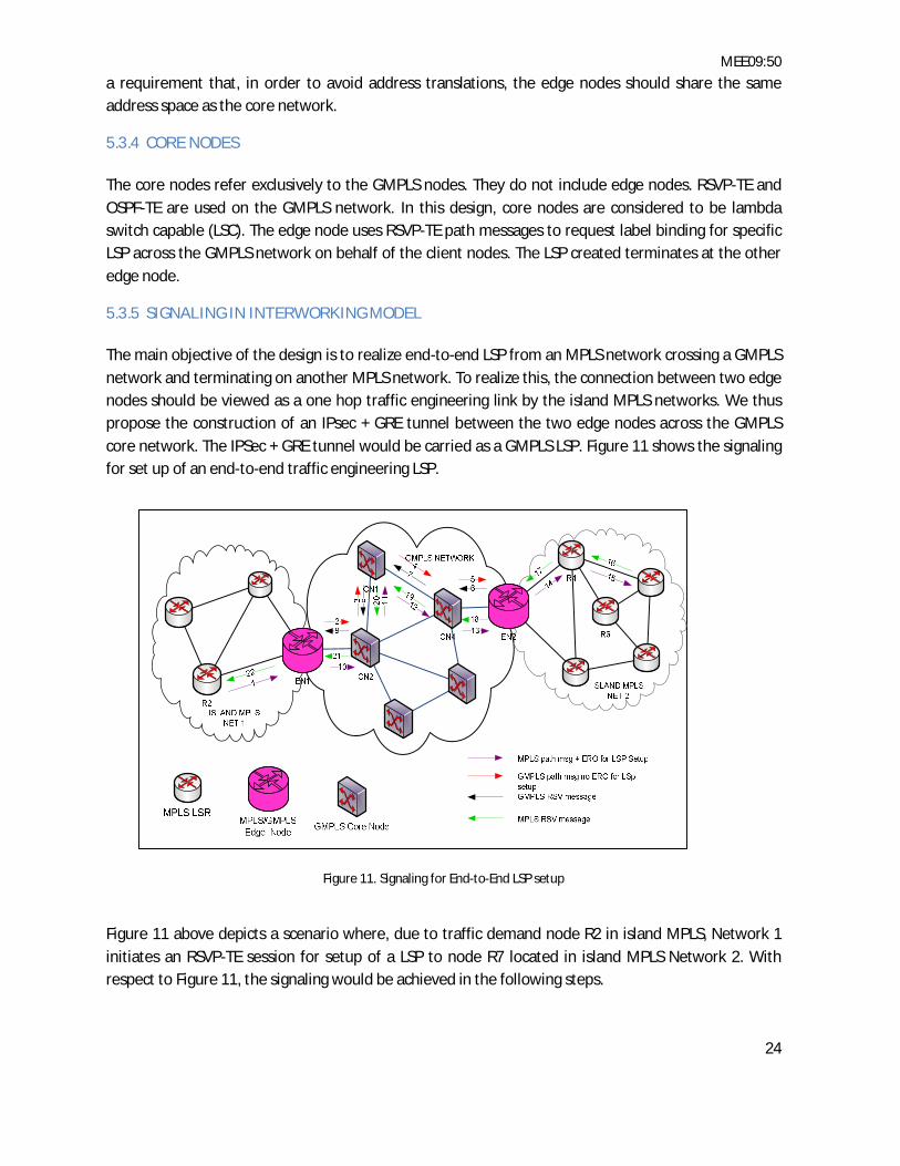
5.3.5 SIGNALING IN INTERWORKING MODEL The main objective of the design is to realize end-to-end LSP from an MPLS network crossing a GMPLS network and terminating on another MPLS network. To realize this, the connection between two edge nodes should be viewed as a one hop traffic engineering link by the island MPLS networks. We thus propose the construction of an IPsec + GRE tunnel between the two edge nodes across the GMPLS core network. The IPSec + GRE tunnel would be carried as a GMPLS LSP. Figure 11 shows the signaling for set up of an end-to-end traffic engineering LSP.
Figure 11. Signaling for End-to-End LSP setup
Figure 11 above depicts a scenario where, due to traffic demand node R2 in island MPLS, Network 1 initiates an RSVP-TE session for setup of a LSP to node R7 located in island MPLS Network 2. With respect to Figure 11, the signaling would be achieved in the following steps.

MEE09:50
25
Step 1: Node R2 sends LABEL_REQUEST + EXPLICIT_ROUTE objects path message to node EN1. Node EN1 resolves the destination of the path message using the UNI interface and reachability information and generates a new GMPLS LABEL_REQUEST path message for setup of an LSP to its corresponding edge node EN2.
Steps 2 to 5: Subsequent core nodes forward the path message until it reaches node EN2.
Steps 6 to 9: EN2 replies through a GMPLS RESV message; allocates the resources at each core node back to node EN1.
Steps 10 to 13: EN1 then forwards the original path message along the IPSec + GRE tunnel which is switched through the GMPLS LSP.
Steps 14-15: Once at EN2 the path message is forwarded to node R4 which further forwards it to node R7.
Steps 16 to 21: R7 sends back an MPLS RESV message allocating resources at each MPLS node including EN1 and EN2 through the GMPLS IPsec + GRE tunnel LSP back to R2.
At this stage, transmission of data packets would commence between nodes R2 and R7 through the end-to-end LSP.

MEE09:50
26

MEE09:50
27
6 PERFORMANCE METRICS Performance metrics are variables providing characteristics associated with a network and which could be analyzed to ascertain its performance. In this thesis, four metrics are used to evaluate the performance of the MPLS signaling protocols. These metrics are:
LSP Packet Delay. LSP Traffic In. Link Throughput. Queuing Delay.
6.1 LSP PACKET DELAY LSP packet delay refers to the time it takes for a packet to be transmitted from the ingress LER to the egress LER. It is composed of five elements, namely; distance delay, serialization delay, queuing delay, protocol delay and forwarding delay. Since the evaluation of the signaling protocols would use the same network topology, only forwarding delay, queuing delay and protocol delay are expected to account for the differences in overall LSP packet delay. Equation (1) shows the mathematical expression of this latency.
푡 = ∑ (푡 , − 푡 , )
푖 (1)
Where 푡 is the average delay, 푡 , is the send time of the 푖 packet at the source node, 푡 , is the
arrival time of the 푖 packet at the sink node, m is the total number of packets and 푖 is the current packet number.
6.2 LSP TRAFFIC IN Refers to the amount of traffic admitted into an LSP at the ingress LER. It gives a good measure of the efficiency that traffic from source nodes or IP client networks is mapped into LSPs for transportation across an MPLS network.
6.3 QUEUING DELAY Queuing delay relates to the time a packet spends in the input buffer of a router interface while waiting for processing. Queuing delay is also incurred at the output buffer of the router interface as the packet waits for serialization. QoS parameters and scheduling mechanism can be configured to influence queuing delay for different traffic types.
6.4 THROUGHPUT Throughput is a measure for the number of packets (amount of data) successfully transmitted across a communication link in a given time. Its measure would help the analysis of packet transmission efficiency of each signaling protocol.

MEE09:50
28

MEE09:50
29
7 SIMULATION TOOLS Simulators provide the opportunity to create, modify and test designed networks in order to establish strengths and weaknesses and to measure their survivability in real environments. To achieve realistic results for analysis, an appropriate simulation tool needs to be used so as to model network scenarios as close as possible to real life situations. Four network simulators were considered for assessment. The simulators are:
OMNet++ OPNET Modeler NS2 GLASS
This thesis work consists of two interrelated parts;
Part I: Evaluation of MPLS control plane signaling protocols.
Part II: Seamless interworking of MPLS and GMPLS networks.
OMNet++, OPNET and NS2 were assessed for suitability to implementation of Part I while GLASS was assessed for possible implementation of Part II.
7.1 OMNet++ OMNet++ is a telecommunication network simulation tool. It has a modularized, component-based, C++ simulation library and framework [25]. In particular, the MPLS module is contained in the INET framework together with other modules. The OMNet++ MPLS module supports the LDP, CR-LDP and RSVP-TE signaling protocols.
OMNet++ is freely accessible for use in an academic environment.
7.2 NS2 NS2 is a freely distributed, open-source, discrete event network simulator. The main objective of NS2 is to facilitate research in the networking field. NS2 is written in C++ and includes an object oriented version of Tcl (OTcl). The MPLS network simulator (MNS) module is an extension of NS2, specifically designed to support MPLS. LDP, CR-LDP and RSVP-TE protocols are all supported in NS2. However, NS2 does not support GMPLS.
NS2 development accepts contributions from independent researchers (third parties). However, lack of documentation on new patches contributed by independent researches, proves to be one of the major drawbacks of NS2. Inconsistencies in the MPLS patch have also been observed.
7.3 OPNET MODELER OPNET provides a broad development environment for supporting communication networks and distributed systems. Three distinguished types of tools are supported in OPNET. These are; model

MEE09:50
30
development tool, simulation execution tool and results analysis tool. The three tools can be used together to model, simulate and analyze results.
MPLS is implemented as a specialized module and supports extensive features such as; static/dynamic LSP, fast reroute and traffic engineering. LDP, CR-LDP and RSVP-TE signaling protocols are all supported in the OPNET MPLS module. GMPLS is however, not supported.
7.4 GMPLS LIGHTWAVE AGILE SWITCHING SIMULATOR An extensive search was carried for a comprehensive MPLS/GMPLS simulator. Only one simulator, namely GLASS, was discovered to contain features that aim to support GMPLS.
GLASS is a Java based simulation tool that uses the scalable simulation framework SSF/SSFNet. SSFNet provides basic networking components such as routers, hosts, links and protocols [26]. The SSFNet network components are modified in GLASS to implement MPLS and GMPLS components such as Optical Cross Connects (OXC), optical links, lambdas and fibers.
Further development of GLASS seems to have stalled with the latest update having been made in 2003.
Having assessed the suitability of the simulators to the objectives of this research, OPNET and GLASS were selected for the implementation of Parts I and II respectively.

MEE09:50
31
8 SIMULATIONS To get an insight into the performance of MPLS signaling protocols, adequate simulations where carried out in OPNET Modeler 14.5. To achieve this, a campus network as illustrated in Figure 12 was created using the following network elements:
5 LERs Soft_Center, BTH_Ronneby, Ronneby_Lib, Grasvik_Lib and Grasvik_BTH.
4 LSRs Node_5, Node_6, Node_7 and Node_8.
6 Hosts; Workstations Digtal_Com, Antenna, Radio_Com, Signal_Proc, Wireless and Lab_Signal.
2 Servers HTTP_FTP_email_server and voip_video_ server.
DS1 links for interconnections
OSPF was selected as the routing protocol for the network.
Figure 12. Simulation Network Diagram

MEE09:50
32
8.1 CONFIGURED APPLICATIONS Applications (traffic types) where carefully selected so that the designed network would carry both elastic and inelastic traffic. This helped in modeling the simulation network as close as possible to real life networks which carry diverse traffic types simultaneously.
Traffic is termed elastic if it can adapt to appreciable changes in network characteristics such as delay, jitter and throughput. Examples of elastic traffic include; Hypertext Transfer Protocol (HTTP), File Transfer Protocol (FTP), Simple Mail Transfer Protocol (SMTP) and Simple Network Management Protocol (SNMP).
If traffic demands consistent (without variations) network characteristics for acceptable service delivery, it is termed inelastic. Real time traffic such as voice and video conferencing are examples of inelastic traffic.
Configuration for QoS took into account the requirements on delay and throughput for both elastic and inelastic traffic. This helped assess each signaling protocol’s ability to deliver applications performance consistent with the configured QoS parameters.
Five applications were configured in the network as shown in Table 4.
Application Situations where used HTTP (Heavy Browsing) Popular web servers e.g. Google, Facebook and Twitter FTP (High Load) File servers e.g. Rapidshare and Ubuntu mirror servers Voice (GSM Quality) VOIP Applications e.g. Skype Video Conferencing (High Resolution Video) Remote news reporting and interviews e.g. CNN and
BBC E-mail (High Load) Popular email servers e.g. Yahoo and Gmail
Table 4. Selected Applications and Examples of Their Uses
Antenna and Digital_Comm workstations were configured for FTP and HTTP respectively. Radio_Com and Signal_Proc were configured for voice and video conferencing respectively. Finally, Wireless and Lab_Signal workstations were configured for HTTP and email respectively.
Two servers; HTTP_FTP_email_server and voip_video_server were configured to support the following services:
HTTP_FTP_email_server HTTP applications service. FTP applications service. email applications service.
voip_video_server
voice applications service. video conferencing applications service.

MEE09:50
33
8.2 CONFIGURED PROFILES An OPNET profile specifies one or a group of applications configured in the application configuration object so that workstations and servers only have to support specific profiles specifying the applications running on them. The following profiles were configured in the network: HTTP_profile, FTP_profile, voice_ profile, video_profile and email_profile.
8.3 CONFIGURED FECs AND LSPs Three FEC were configured namely, HTTP_FTP_fec, voice_video_fec and email_HTTP_fec. FECs specify grouping of traffic that should receive the same treatment in an MPLS network. In this work, all FECs were configured with respect to source IP address. The MPLS configuration object palette offers options for configuring FECs.
Three dynamic explicit routed LSPs (loose) were configured in the network. Loose LSPs were preferred to examine the LSP formation characteristics of both RSVP-TE and CR-LDP. The loosely defined ER-LSPs were:
Soft_center <-> Grasvik_BTH (via node_8) BTH_Ronneby <-> Grasvik_Lib (via node_8) Ronneby_Lib <-> Grasvik_BTH (via Grasvik-Lib)
8.4 CONFIGURED TRAFFIC TRUNKS Traffic trunks consist of configurable attributes that characterizes FECs in an MPLS network. Each FEC is associated with a specific traffic trunk. The attributes are: out of profile action, traffic profile and traffic class.
In the network, three traffic trunks were configured; HTTP_FTP_trunk, voice_video_trunk and email_HTTP_trunk. Configuration of traffic trunks is done in the MPLS configuration object.
8.5 TRAFFIC MAPPING CONFIGURATION Traffic mapping configuration is done on the ingress LER. It is a process of associating interface(s) to a specific FEC which, in turn, is associated to a traffic trunk and an LSP. Traffic mapping configurations were thus performed on Soft_Center LER, BTH_Ronneby LER and Ronneby_Lib LER.
8.6 PROJECT SCENARIOS AND RESULTS The thesis project (THESIS_FINAL_PROJECT) was configured with four different scenarios namely:
1. RSVPTE_ERLSP_LOOSE (RSVP-TE without QoS). 2. CRLDP_ERLSP_LOOSE (CR-LDP without QoS). 3. RSVPTE_ERLSP_LOOSE_QoS (RSVP-TE with QoS). 4. CRLDP_ERLSP_LOOSE_QoS (CR-LDP with QoS).

MEE09:50
34
Simulation scenarios were run for 2 hours and following statistics were collected for analysis:
LSP Delay. LSP Traffic In. Queuing Delay. Throughput.
8.6.1 RSVPTE_ERLSP_LOOSE AND CRLDP_ERLSP_LOOSE SCENARIOS WITH NO QoS To model scenarios with no QoS, the default (FIFO) queuing behavior on all router interfaces was retained. Routers implemented tail drop whenever congestion occurred.
A dynamic ER-LSP can be configured as loose or strict. When configured as loose, certain nodes or links could be specified to form part of the LSP. If configured as strict, the complete path needs to be specified including all links and nodes in preferred order from the ingress to the egress node. In this work, only loose configurations for the LSPs were considered.
For RSVPTE_ERLSP_LOOSE scenario, the configurations for FECs and LSPs, profiles and applications were configured as described in section 9.3. The signaling protocol was also explicitly specified as RSVP-TE. All traffic trunks in the network were configured as follows:
Traffic Profile Max Bit Rate: 32kbps Max Burst Size: 32kbits Average Bit Rate: 32kbps Peak Burst Size 32kbits Out of profile action: Discard
For CRLDP_ERLSP_LOOSE scenario, all the configurations were the same as those for RSVPTE_ERLSP_LOOSE scenario except that, this time, the signaling protocol was explicitly specified as CR-LDP.
Figure 13 and Figure 14 show the packet delay on the Soft_center <-> Grasvik_BTH LSP and the Ronneby_Lib <-> Grasvik_BTH LSP respectively.

MEE09:50
35
Figure 13. CR-LDP and RSVP-TE LSP Packet Delay for Soft_center <-> Grasvik_BTH LSP
Figure 14. CR-LDP and RSVP-TE LSP Packet Delay for Ronneby_Lib <-> Grasvik_BTH LSP
8.6.1.1 LSP PACKET DELAY OBSERVATIONS The Soft_Center <-> Grasvik_BTH LSP carried HTTP (heavy browsing) and FTP (high load). With RSVP-TE used as the signaling protocol, Figure 13 shows that the peak delay of 10ms is attained just after completion of setting up the LSP. It however, decreases quite rapidly to settle to a value between 3ms and 4ms for the rest of the simulation.
0
0.001
0.002
0.003
0.004
0.005
0.006
0.007
0.008
0.009
0.01
0
216
432
648
864
1080
1296
1512
1728
1944
2160
2376
2592
2808
3024
3240
3456
3672
3888
4104
4320
4536
4752
4968
5184
5400
5616
5832
6048
6264
6480
6696
6912
7128
dela
y ti
me(
sec)
Simulation Progress (sec)
Soft_Center<->Grasvik_BTH LSP Delay No QoS
CRLDP_ERLSP_LOOSE RSVP_ERLSP_LOOSE
0
0.05
0.1
0.15
0.2
0.25
0.3
0.35
0.4
0.45
0
216
432
648
864
1080
1296
1512
1728
1944
2160
2376
2592
2808
3024
3240
3456
3672
3888
4104
4320
4536
4752
4968
5184
5400
5616
5832
6048
6264
6480
6696
6912
7128
LSP
Del
ay (s
ec)
Simulation Progress (sec)
Ronneby_Lib<->Grasvik_BTH LSP Delay No QoS
CRLDP_ERLSP_LOOSE RSVP_ERLSP_LOOSE
MEE09:50
36
It is also observed that the average packet delay for CR-LDP rises steadily from 1.5ms in the initial stages and attains a maximum of 4.7ms at 36 minutes. It finally settles down to between 3.5ms and 4.5ms for the rest of the simulation.
Figure 14 shows the average packet delay for Ronneby_Lib <-> Grasvik_BTH LSP carrying email (high load) and HTTP (heavy browsing). Once the LSP has been setup, both CR-LDP and RSVP-TE packet delay is well below 3ms until about 50 minutes into the simulation when CR-LDP average delay starts to rise to reach 0.4s at the end of simulation. RSVP-TE LSP delay remained below 3ms for the entire simulation period.
The results in Figure 13 are consistent with the underlying signaling protocols operation and traffic types carried by the LSP. The RSVP-TE signaled LSP experienced high delay in the initial stage of the simulation. This is because all nodes along the LSP try to associate the traffic flow to resources that may have been reserved by RSVP the first time it is encountered increasing thus the processing delay. The delay rapidly decreases as subsequent packets are only subjected to label inspection before being forwarded. On the other hand, the CR-LDP signaled LSP has a very low delay at the beginning when there is low traffic in the network. Packets are thus subjected to short queues at the input and output buffers along the LSP. Another reason is that HTTP and FTP uses TCP, which employs slow start resulting in the initial packets experiencing low delay.
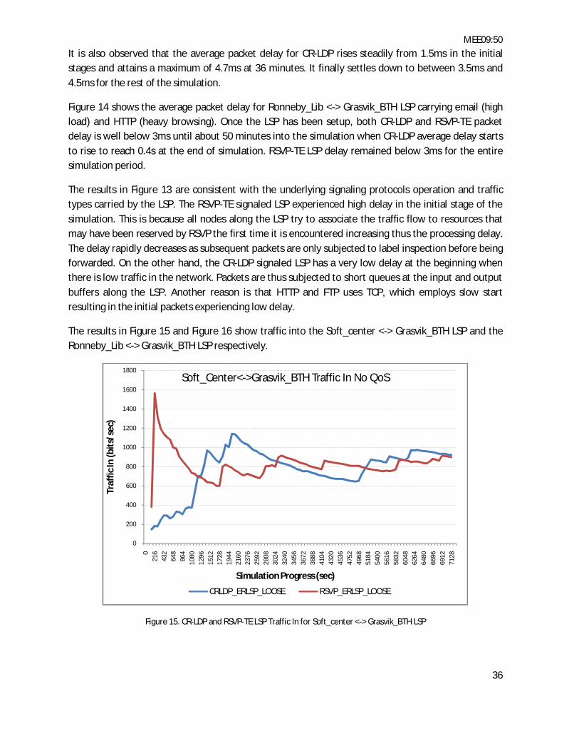
The results in Figure 15 and Figure 16 show traffic into the Soft_center <-> Grasvik_BTH LSP and the Ronneby_Lib <-> Grasvik_BTH LSP respectively.
Figure 15. CR-LDP and RSVP-TE LSP Traffic In for Soft_center <-> Grasvik_BTH LSP
0
200
400
600
800
1000
1200
1400
1600
1800
021
643
264
886
410
8012
9615
1217
2819
4421
6023
7625
9228
0830
2432
4034
5636
7238
8841
0443
2045
3647
5249
6851
8454
0056
1658
3260
4862
6464
8066
9669
1271
28
Traf
fic In
(bit
s/se
c)
Simulation Progress (sec)
Soft_Center<->Grasvik_BTH Traffic In No QoS
CRLDP_ERLSP_LOOSE RSVP_ERLSP_LOOSE

MEE09:50
37
Figure 16. CR-LDP and RSVP-TE LSP Traffic In for Ronneby_Lib <-> Grasvik_BTH LSP
8.6.1.2 LSP TRAFFIC IN OBSERVATIONS Traffic into Soft_center <-> Grasvik_BTH LSP carrying HTTP (heavy browsing) and FTP (high load) rose sharply to a value of 1600bps at the start of simulation but stabilized at between 600bps and 900bps in the case of RSVP-TE. Traffic into the CR-LDP LSP rose from 150bps to attain a maximum value of 1100bps 36 minutes into the simulation. By the end of the simulation, traffic into the LSP using both signaling protocols was almost equal at 900bps.
Traffic admitted into Ronneby_Lib <-> Grasvik_BTH LSP rose to a peak value of 650bps for CR-LDP and 550bps for RSVP-TE. At 90 minutes into the simulation, traffic into the RSVP-TE signaled LSP overtook that of the CR-LDP signaled LSP as the latter declined.
The results in Figure 15 are justifiable in that, the RSVP-TE signaled LSP admits more traffic at the beginning once the LSP has been setup, but due to inefficient control and management (i.e. RSVP-TE uses unreliable UDP for control and management of LSPs), the traffic (HTTP and FTP) into the LSP gradually decreases as the simulation progresses. In Figure 16 the traffic in just after LSP setup is identical for both RSVP-TE and CR-LDP. However, while CR-LDP efficiently manages and controls its LSP (i.e. CR-LDP uses reliable TCP for control and management of LSPs) to maintain relatively high traffic into the LSP, traffic in for RSVP-TE signaled LSP drops.
The results in Figure 17 are for throughput of the serial link between Grasvik_Lib and Grasvik_BTH in the direction of Grasvik_BTH.
0
100
200
300
400
500
600
700
021
6
432
648
864
1080
1296
1512
1728
1944
2160
2376
2592
2808
3024
3240
3456
3672
3888
4104
4320
4536
4752
4968
5184
5400
5616
5832
6048
6264
6480
6696
6912
7128
Traf
fic In
(bit
s/se
c)
Simulation Progress (sec)
Ronneby_Lib<->Grasvik_BTH Traffic In No QoS
CRLDP_ERLSP_LOOSE RSVP_ERLSP_LOOSE
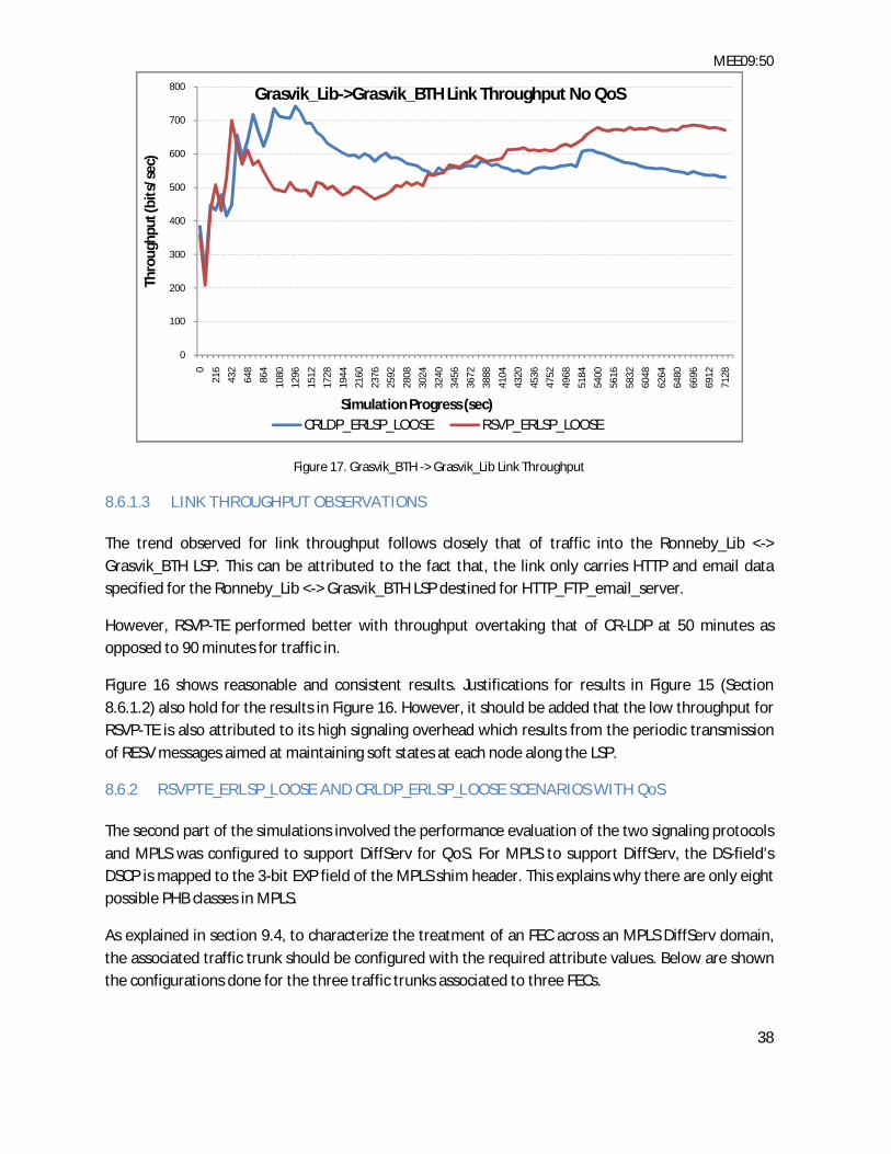
MEE09:50
38
Figure 17. Grasvik_BTH -> Grasvik_Lib Link Throughput
8.6.1.3 LINK THROUGHPUT OBSERVATIONS The trend observed for link throughput follows closely that of traffic into the Ronneby_Lib <-> Grasvik_BTH LSP. This can be attributed to the fact that, the link only carries HTTP and email data specified for the Ronneby_Lib <-> Grasvik_BTH LSP destined for HTTP_FTP_email_server.
However, RSVP-TE performed better with throughput overtaking that of CR-LDP at 50 minutes as opposed to 90 minutes for traffic in.
Figure 16 shows reasonable and consistent results. Justifications for results in Figure 15 (Section 8.6.1.2) also hold for the results in Figure 16. However, it should be added that the low throughput for RSVP-TE is also attributed to its high signaling overhead which results from the periodic transmission of RESV messages aimed at maintaining soft states at each node along the LSP.
8.6.2 RSVPTE_ERLSP_LOOSE AND CRLDP_ERLSP_LOOSE SCENARIOS WITH QoS The second part of the simulations involved the performance evaluation of the two signaling protocols and MPLS was configured to support DiffServ for QoS. For MPLS to support DiffServ, the DS-field’s DSCP is mapped to the 3-bit EXP field of the MPLS shim header. This explains why there are only eight possible PHB classes in MPLS.
As explained in section 9.4, to characterize the treatment of an FEC across an MPLS DiffServ domain, the associated traffic trunk should be configured with the required attribute values. Below are shown the configurations done for the three traffic trunks associated to three FECs.
0
100
200
300
400
500
600
700
800
0
216
432
648
864
1080
1296
1512
1728
1944
2160
2376
2592
2808
3024
3240
3456
3672
3888
4104
4320
4536
4752
4968
5184
5400
5616
5832
6048
6264
6480
6696
6912
7128
Thro
ughp
ut (b
its/
sec)
Simulation Progress (sec)
Grasvik_Lib->Grasvik_BTH Link Throughput No QoS
CRLDP_ERLSP_LOOSE RSVP_ERLSP_LOOSE

MEE09:50
39
HTTP_FTP_fec Traffic Profile
Max Bit Rate: 64kbps Max Burst Size: 32kbits Average Bit Rate: 32kbps Peak Burst Size 32kbits
Out of profile action: Discard Traffic Class: AF21
email_HTTP_fec
Traffic Profile Max Bit Rate: 64kbps Max Burst Size: 32kbits Average Bit Rate: 32kbps Peak Burst Size 32kbits
Out of profile action: Discard Traffic Class: AF31
voice_video_fec
Traffic Profile Max Bit Rate: 128kbps Max Burst Size: 32kbits Average Bit Rate: 32kbps Peak Burst Size 32kbits
Out of profile action: Discard Traffic Class: EF
Through the QoS configuration object, the scheduling mechanism based on DSCP values was set to be WFQ. In addition, all MPLS domain router interfaces were configured to support WFQ based on DSCP for treatment decisions of the FECs at each node. Simulations were run, and statistics were collected for analysis.
LSP packet delays for RSVP-TE and CRLDP are shown in Figure 18 and Figure 19 respectively.

MEE09:50
40
Figure 18. CR-LDP and RSVP-TE LSP Packet Delay for Soft_center <-> Grasvik_BTH LSP with QoS
Figure 19. CR-LDP and RSVP-TE LSP Packet Delay for Ronneby_Lib <-> Grasvik_BTH LSP with QoS
8.6.2.1 LSP PACKET DELAY OBSERVATIONS (With QoS) The traffic trunk associated with the FEC (HTTP_FTP_fec) carried by Soft_center <-> Grasvik_BTH LSP is configured with AF21 PHB. This LSP shares the serial link between node_8 and Grasvik_BTH with the BTH_Ronneby<->Grasvik_Lib LSP, which carries voice_video_fec (configured with EF PHB).
0
0.001
0.002
0.003
0.004
0.005
0.006
0.007
0.008
0.009
021
643
264
886
410
8012
9615
1217
2819
4421
6023
7625
9228
0830
2432
4034
5636
7238
8841
0443
2045
3647
5249
6851
8454
0056
1658
3260
4862
6464
8066
9669
1271
28
Del
ay (s
ec)
Simulation Progress (sec)
Soft_Center<->Grasvik_BTH LSP Delay With QoS
CRLDP_ERLSP_LOOSE_QoS RSVP_ERLSP_LOOSE_QoS
0
0.001
0.002
0.003
0.004
0.005
0.006
0.007
0.008
021
643
264
886
410
8012
9615
1217
2819
4421
6023
7625
9228
0830
2432
4034
5636
7238
8841
0443
2045
3647
5249
6851
8454
0056
1658
3260
4862
6464
8066
9669
1271
28
Del
ay (s
ec)
Simulation Progress (sec)
Ronneby_Lib<->Grasvik_BTH LSP Delay With QoS
CRLDP_ERLSP_LOOSE_QoS RSVP_ERLSP_LOOSE_QoS

MEE09:50
41
The EF traffic receives preferential treatment compared to AF21 traffic at the egress interface of node_8 connecting to Grasvik_BTH. However, the delay for both the CR-LDP and RSVP-TE signaled LSPs continued to drop steadily from a peak of 8ms to 4ms and 3.7ms respectively by the end of simulation.
The Ronneby_Lib <-> Grasvik_BTH LSP carries email_HTTP_fec whose associated trunk is configured with AF31 PHB. It has the least priority class in the network. The completed paths for both RSVP and CR-LDP signaled LSPs follow the same route. All the links along the route (Ronneby_Lib to Grasvik_BTH) only carry email and HTTP. Thus, despite having low priority, traffic is still forwarded with low delay. This is evidenced by the graphs in Figure 19.
In Figure 18, the results show identical packet delay performance for RSVP-TE and CR-LDP. The performance is attributed to common PHB (AF21) and efficient traffic policing managed by WFQ. After the simulation settled at about 2376 seconds, the packet delay associated with both signaling protocols increased slightly compared to the case without QoS. This is because, the benefits of QoS favored real time traffic (i.e. voice and video configured with EF PHB) on the shared link between node_8 and Grasvik_BTH. In Figure 19, notable difference in delay performance between RSVP-TE and CR-LDP throughout the simulation period can only be associated to the higher processing overhead/delay associated with RSVP-TE.
Traffic into Soft_center <-> Grasvik_BTH LSP and Ronneby_Lib <-> Grasvik_BTH LSP is shown in Figure 20 and Figure 21 respectively.
Figure 20. CR-LDP and RSVP-TE LSP Traffic In for Soft_center <-> Grasvik_BTH LSP with QoS
0
500
1000
1500
2000
2500
0
216
432
648
864
1080
1296
1512
1728
1944
2160
2376
2592
2808
3024
3240
3456
3672
3888
4104
4320
4536
4752
4968
5184
5400
5616
5832
6048
6264
6480
6696
6912
7128
Traf
fic In
(bit
s/se
c)
Simulation Progress (sec)
Soft_Center<->Grasvik_BTH Traffic InWith QoS
CRLDP_ERLSP_LOOSE_QoS RSVP_ERLSP_LOOSE_QoS

MEE09:50
42
Figure 21. CR-LDP and RSVP-TE LSP Traffic In for Ronneby_Lib <-> Grasvik_BTH LSP with QoS
8.6.2.2 LSP TRAFFIC IN OBSERVATIONS (With QoS) The traffic carried in the Soft_Center <-> Grasvik_BTH LSP shares a common serial link between node_8 and Grasvik_BTH with traffic in the BTH_Ronneby<->Grasvik_Lib LSP. Due to the EF PHB associated with BTH_Ronneby<->Grasvik_Lib LSP traffic, a decline in traffic in Soft_Center <-> Grasvik_BTH LSP is observed as node_8 gives priority to real time traffic. This is evidenced in Figure 20.
Just after LSP setup is complete, the two signaling protocols recorded identical traffic into their respective LSPs. Soon after, the traffic in dropped gradually for both signaling protocols as their traffic (configured with AF21) was subjected to longer queuing delay in the input and output buffers. Longer queuing delays result in lower rate of acknowledgement messages being received by the sender which ultimately forces TCP to reduce the rate of transmission. This also explains the fairly constant traffic in performance on the Ronneby_Lib <-> Grasvik_BTH LSP whose corresponding packet delay is shown in Figure 19.
Throughput on the link Grasvik_BTH -> Grasvik_Lib is shown in Figure 22.
0
100
200
300
400
500
600
0
216
432
648
864
1080
1296
1512
1728
1944
2160
2376
2592
2808
3024
3240
3456
3672
3888
4104
4320
4536
4752
4968
5184
5400
5616
5832
6048
6264
6480
6696
6912
7128
Traf
fic In
(bit
s/se
c)
Simulation Progress (sec)
Ronneby_Lib<->Grasvik_BTH Traffic In With QoS
CRLDP_ERLSP_LOOSE_QoS RSVP_ERLSP_LOOSE_QoS

MEE09:50
43
Figure 22. Grasvik_BTH -> Grasvik_Lib Link Throughput
8.6.2.3 LINK THROUGHPUT OBSERVATIONS (With QoS) Throughout the simulation period, RSVP-TE signaled LSP throughput performed better than the CR-LDP signaled LSP maintaining the rate between 600 and 700bps. Both signaling protocols performed consistently throughout the simulation period maintaining a throughput within 100bps from the maximum.
The link throughput follows closely that of traffic into the Ronneby_Lib <-> Grasvik_BTH LSP. This is attributed to the fact that, the link only carries HTTP and email data specified for the Ronneby_Lib <-> Grasvik_BTH LSP destined for HTTP_FTP_email_server. For this reason the justification of results given in section 8.6.2.2 also holds for the result in Figure 22.
Queuing delay for all scenarios on the link Grasvik_BTH -> Grasvik_Lib is shown in Figure 23.
0
100
200
300
400
500
600
700
800
0
216
432
648
864
1080
1296
1512
1728
1944
2160
2376
2592
2808
3024
3240
3456
3672
3888
4104
4320
4536
4752
4968
5184
5400
5616
5832
6048
6264
6480
6696
6912
7128
Thro
ughp
ut (b
its/
sec)
Simulation Progress (sec)
Grasvik_Lib->Grasvik_BTH Link Throughput With QoS
CRLDP_ERLSP_LOOSE_QoS RSVP_ERLSP_LOOSE_QoS

MEE09:50
44
Figure 23. Grasvik_BTH -> Grasvik_Lib Link Queuing Delay (With and Without QoS)
8.6.2.4 LINK QUEUING DELAY OBSERVATIONS WITH AND WITHOUT QoS Without QoS, RSVP-TE records the highest queuing delay of 1.5ms at the start of the simulation. This decays rapidly to settle at about 0.5ms for the rest the simulation. Overall, CR-LDP performs better than RSVP-TE with an average queuing delay of 0.42ms throughout the simulation period.
After the introduction of QoS, queuing delay for RSVP-TE dropped significantly, but was still marginally higher than that recorded for CR-LDP.
Queuing delay on the link associated with RSVP-TE without QoS was high at the beginning of the simulation. This is because Grasvik_Lib and Grasvik_BTH LERs try to associate the traffic flow to resources that may have been reserved by RSVP the first time it is encountered increasing thus the processing delay. The delay rapidly decreases as subsequent packets are only subjected to label inspection before being forwarded. On the other hand, the delay associated with CR-LDP was very low at the beginning when there was low traffic in the network. For the QoS case, the link in question carried real time traffic (i.e. voice and video configured with EF PHB). Therefore, the initial high processing delay was countered by the high priority PHB (EF) which resulted in an improved queuing delay for the RSVP-TE associated traffic. The delay associated with CR-LDP traffic also improved but only marginally.
0
0.0002
0.0004
0.0006
0.0008
0.001
0.0012
0.0014
0.0016
0.0018
0
216
432
648
864
1080
1296
1512
1728
1944
2160
2376
2592
2808
3024
3240
3456
3672
3888
4104
4320
4536
4752
4968
5184
5400
5616
5832
6048
6264
6480
6696
6912
7128
Del
ay (s
ec)
Simulation Progress (sec)
Grasvik_BTH->Grasvik_Lib Link Queueing Delay
CRLDP_ERLSP_LOOSE RSVP_ERLSP_LOOSE
CRLDP_ERLSP_LOOSE_QoS RSVP_ERLSP_LOOSE_QoS
MEE09:50
45
9 CONCLUSION
The objectives of this thesis work were to carry out a detailed assessment of the implementation of MPLS signaling protocols and evaluate how each impact on the QoS for different types of user applications. Furthermore, a solution for the seamless interworking of MPLS and GMPLS was proposed.
In Chapter 2 and 3, a review of MPLS and GMPLS protocols was carried out. Special attention was given to the control plane signaling protocols, LDP, CR-LDP and RSVP-TE. Message types, PDU structure, LSP setup procedure and unique features were discussed for each protocol.
A solution to seamless interworking of MPLS and GMPLS networks was discussed in Chapter 6. The solution adopts the Overlay model in which, two client MPLS networks are interconnected through a GMPLS server network. The signaling procedure for the proposed interworking model was also outlined.
Simulations for evaluating the performance of MPLS signaling protocols with regard to QoS were carried out using OPNET Modeler 14.5. Appropriate scenarios were created in order to compare the performance of RSVP-TE and CR-LDP, with and without QoS. Statistics were collected and presented.
In all scenarios loose ER-LSPs were configured. With and without QoS, both RSVP-TE and CR-LDP signaled LSPs followed the same routes through the network. In all cases, both signaling protocols completed the paths between the explicitly defined LSRs using OSPF routing protocol information. This shows that both signaling protocols use control-driven LSPs to complete paths in the loosely defined portions of the network.
With no QoS parameters set (i.e. using FIFO scheduling), packet delay in the RSVP-TE signaled LSP was lower than that in the CR-LDP signaled LSP. The difference varied between 0ms and 1.5ms during the simulation period. CR-LDP performed better than RSVP-TE when QoS parameters were configured in the network.
Without QoS, the LSP configured to carry HTTP and FTP associated with AF31 PHB admitted more traffic when signaled with CR-LDP than with RSVP-TE. When QoS was enabled, the RSVP-TE signaled LSP admitted more traffic than the CR-LDP signaled LSP.
The overall throughput performance of the two signaling protocols was similar for the duration of the simulation without QoS. However, the throughput fluctuated greatly over the course of the simulation. With QoS enabled, the RSVP-TE signaled LSP recorded a higher throughput for the entire duration of the simulation. For both signaling protocols, throughput remained steady throughout the simulation period.
CR-LDP performed much better than RSVP-TE in terms of queuing delay with no QoS parameters configured. When QoS was introduced, the queuing delay performance of RSVP-TE improved greatly but was still slightly lower than that of CR-LDP.

MEE09:50
46

MEE09:50
47
10 FUTURE WORK In this thesis, a proposal for interworking of MPLS and GMPLS detailing the control plane routing and signaling procedures was made. However, simulations could not be done because a simulation tool (open-source or commercial) supporting GMPLS could not be found. Therefore, the implementation, simulation and analysis of the proposed solution are left as future work to interested researchers.

MEE09:50
48

MEE09:50
49
APPENDIX A
Loose ER-LSPs were configured as shown in Figure A-1.
Figure A-1. Configured loose ER-LSPs
The LSP routes completed by the three ER-LSPs are shown in Figure A-2, Figure A-3 and Figure A-4.
Figure A-2. LSP BTH_Ronneby <-> Grasvik_Lib
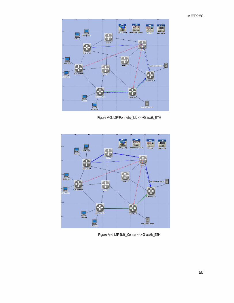
MEE09:50
50
Figure A-3. LSP Ronneby_Lib <-> Grasvik_BTH
Figure A-4. LSP Soft_Center <-> Grasvik_BTH

MEE09:50
51
REFERENCES
[1] Rosen E., Viswanathan A., and Callon R., "Multiprotocol Label Switching Architecture", RFC3031, January 2001. Available: HTTP://www.ietf.org/rfc/rfc3031.txt
[2] Hussain I. "Overview of MPLS Technology and Traffic Engineering Applications", INCC International Conference on Networking and Communication, June 2004. Page(s):xvi
[3] Andersson L. and Bryant S. "The IETF Multiprotocol Label Switching Standard: The MPLS Transport Profile Case", IEEE Internet Computing, July-Aug. 2008, Page(s):69 – 73
[4] Rosen E., Tappan D. and Fedorkow G. "MPLS Label Stack Encoding", RFC3032 January 2001. Available: HTTP://www.ietf.org/rfc/rfc3032.txt
[5] Cunha D.V. and Bressan, G. "Generalized MPLS - an overview", ConTEL International Conference on Telecommunications, 11-13 June 2003 Page(s):435 – 442
[6] (International Engineering Consortium) (2009, April, 28). Title (The IETF Multiprotocol Label Switching Standard: Tutorial), Available: HTTP://www.iec.org/online/tutorials/mpls/
[7] Adami D., Carlotti N., Giordano S., Pagano M. and Repeti M. "Performance Study of the Control and Forwarding Planes in a High Speed MPLS network", Next Generation Internet Networks, 18-20 April 2005 Page(s):274 – 280
[8] Andersson L., Doolan P., Feldman N., Fredette A., and B. Thomas "LDP Specification", RFC 3036, January 2001. Available: HTTP://www.ietf.org/rfc/rfc3036.txt
[9] Jamoussi B., Andersson L., Callon R., Dantu R., Wu L., Doolan P., Worster T., Feldman N., Fredette A., Girish M., Gray E., Heinanen J., Kilty T. and A. Malis, "Constraint-Based LSP Setup using LDP", RFC3212, January 2002.
[10] Hodzic, H. and Zoric, S., “Traffic engineering with constraint based routing in MPLS networks,” ELMAR, 2008. 50th International Symposium , Volume 1, 10-12 Sept. 2008 Page(s):269 – 272
[11] Braden R., Zhang L., Berson S., Herzog S., and S. Jamin, "Resource ReSerVation Protocol (RSVP) Functional Specification", RFC 2205, September 1997. Available: HTTP://www.ietf.org/rfc/rfc2205.txt
[12] Porwal, M.K., Yadav, A. and Charhate, S.V.,” Traffic Analysis of MPLS and Non MPLS Network including MPLS Signaling Protocols and Traffic Distribution in OSPF and MPLS,” Emerging Trends in Engineering and Technology, 2008. ICETET '08. First International Conference on 16-18 July 2008, Page(s):187 - 192
[13] Awduche D., Berger L., Gan D., Li T., Srinivasan V., and G. Swallow, "RSVP-TE: Extensions to RSVP for LSP Tunnels", RFC 3209, December 2001. Available: HTTP://www.ietf.org/rfc/rfc3209.txt
[14] “Generalized Multiprotocol Label Switching (GMPLS),” [html]. Available: HTTP://www.iec.org/online/tutorials/gmpls/index.asp Accessed on April 28, 2009

MEE09:50
52
[15] Mannie E., “Generalized Multi-Protocol Label Switching (GMPLS) Architecture", RFC 3945, October 2004. Available: HTTP://www.ietf.org/rfc/rfc3945.txt and HTTP://www.rfc-editor.org/rfc/rfc3945.txt
[16] Shimazaki, D., Oki, E., Shiomoto, K. and Yamanaka, N., “GMPLS and IP+MPLS interworking technologies - routing and signaling,” HPSR Workshop on High Performance Switching and Routing, 2004, Page(s):27 - 31
[17] Salcedo Parra, O.J., Hernandez, C.A., Puente, F.J. and Sarmiento, D.L., “Performance Evaluation in IP/MPLS Networks,” International Conference on Wireless Communications, Networking and Mobile Computing, WiCOM, 12-14 Oct. 2008, Page(s):1 – 4
[18] Rahman M.A., Kabir A.H., Lutfullah K.A.M., Hassan M.Z. and Amin M.R., “Performance analysis and the study of the behavior of MPLS protocols,” International Conference on Computer and Communication Engineering ICCCE, 13-15 May 2008, Page(s):226 – 229
[19] “A comparison of Multiprotocol Label Switching Traffic Engineering Initiatives,” [html]. Available: HTTP://www.iec.org/online/tutorials/mpls_traffic/index.asp. Accessed on April 28, 2009
[20] K. Kumaki, “Interworking Requirements to Support Operation of MPLS-TE over GMPLS Networks ", RFC5146, March 2008. Available: HTTP://www.ietf.org/rfc/rfc5146.txt, and HTTP://www.apps.ietf.org/rfc/rfc5146.html
[21] K. Ogaki, T. Otani, M. Tatipamula, K. Kumaki and H. Tanaka, “Migration of a GMPLS network into an existing IP/MPLS by border-peer router model,” European Conference on Optical Communication, vol. 2, pp. 221-222, Sept. 2005.
[22] D. Shimazaki, E. Oki, K. Shiomoto and N. Yamanaka, “GMPLS and IP+MPLS interworking technologies - routing and signaling,” Workshop on High Performance Switching and Routing, pp. 27 – 31, May. 2004.
[23] Swallow, G., Drake, J., Ishimatsu, H., and Y. Rekhter,"Generalized Multiprotocol Label Switching (GMPLS) User-Network Interface (UNI): Resource ReserVation Protocol-Traffic Engineering (RSVP-TE) Support for the Overlay Model", RFC 4208, October 2005. Available: HTTP://www.ietf.org/rfc/rfc4208.txt
[24] K. V. Moodely and H. E Hanrahan, “Investigation into Performance Metrics for Connection Admission Control in an MPLS Simulated Network,” Centre for Telecommunication Access and Services,
[25] OMNet++ 4.0), (2009, May, 21). Title (INET Framework for OMNet++ 4.0,), Available: HTTP://www.omnetpp.org/.
[26] (NIST-Advanced Network Technologies Division Software Distribution), (2009, May, 24). Title (GMPLS Light wave Agile Switching Simulator), Available: HTTP://snad.ncsl.nist.gov/glass/
[27] Davie B., Lawrence J., and McCloghrie K., “MPLS using LDP and ATM VC Switching", RFC 3035, January 2001. Available: HTTP://www.rfc-editor.org/rfc/rfc3035.txt


