Embed Size (px)
Citation preview
UNIVERSITY CARLOS III OF MADRID
Department of Telematics Engineering
Master of Science Thesis
Performance Evaluation of IEEE 802.11aa MAC Enhancementsfor Robust Audio Video Streaming
Author: Lucas Eznarriaga BarrancoDipl.Eng. in Telecommunications
Supervisor: Albert Banchs Roca, Ph.D.
Leganes, September 2011

Abstract
Video traffic is foreseen to account for the majority of the Internet traffic in the nearfuture. While the demand of video transmission keeps growing, the vast majority of wire-less equipment deployed in the home environment, based on IEEE 802.11, does not supportrobust multicast transmission that video applications require. In order to cope with the in-creasing demand of multimedia traffic, the IEEE 802.11aa Task Group is standardizing newmechanisms that allow the efficient transmission of unicast/multicast multimedia flows inWireless LAN. In this thesis, we provide analytical models for the throughput of new mech-anisms proposed by the Task Group and we validate them through simulation. We also studythe reliability via simulation, providing insight into new methods included in the standard tohandle group addressed frames.
i

Table of Contents
Abbreviations v
1 Introduction 1
2 Streaming on IEEE 802.11 WLANs 32.1 Multimedia Transmission over Legacy IEEE 802.11 WLANs . . . . . . . . 3
2.1.1 Multicast Service . . . . . . . . . . . . . . . . . . . . . . . . . . . 32.1.2 Unicast Service . . . . . . . . . . . . . . . . . . . . . . . . . . . . 42.1.3 Prioritization . . . . . . . . . . . . . . . . . . . . . . . . . . . . . 4
2.2 MAC Enhancements for Robust Audio Video Streaming: IEEE 802.11aa . . 42.2.1 Stream Classification Service . . . . . . . . . . . . . . . . . . . . 52.2.2 Groupcast with Retries Service . . . . . . . . . . . . . . . . . . . . 5
2.3 Related Work . . . . . . . . . . . . . . . . . . . . . . . . . . . . . . . . . 7
3 Performance Analysis 103.1 Scenario and Assumptions . . . . . . . . . . . . . . . . . . . . . . . . . . 103.2 No-Ack/No-Retry Model . . . . . . . . . . . . . . . . . . . . . . . . . . . 11
3.2.1 Throughput analysis . . . . . . . . . . . . . . . . . . . . . . . . . 113.2.2 Analysis of the τ . . . . . . . . . . . . . . . . . . . . . . . . . . . 13
3.3 GCR Unsolicited Retry Model . . . . . . . . . . . . . . . . . . . . . . . . 133.4 GCR Directed Multicast Model . . . . . . . . . . . . . . . . . . . . . . . . 13
3.4.1 Throughput analysis . . . . . . . . . . . . . . . . . . . . . . . . . 133.4.2 Analysis of the τ . . . . . . . . . . . . . . . . . . . . . . . . . . . 14
3.5 GCR Immediate Block Ack Model . . . . . . . . . . . . . . . . . . . . . . 143.5.1 Throughput Analysis . . . . . . . . . . . . . . . . . . . . . . . . . 14
3.6 GCR Delayed Block Ack Model . . . . . . . . . . . . . . . . . . . . . . . 153.6.1 Throughput analysis . . . . . . . . . . . . . . . . . . . . . . . . . 153.6.2 Analysis of the τ . . . . . . . . . . . . . . . . . . . . . . . . . . . 16
4 Performance Evaluation 184.1 Throughput Performance . . . . . . . . . . . . . . . . . . . . . . . . . . . 18
4.1.1 No-Ack/No-Retry . . . . . . . . . . . . . . . . . . . . . . . . . . 184.1.2 GCR Unsolicited Retry . . . . . . . . . . . . . . . . . . . . . . . . 204.1.3 GCR Directed Multicast Service . . . . . . . . . . . . . . . . . . . 214.1.4 GCR Immediate Block Ack . . . . . . . . . . . . . . . . . . . . . 23
ii

iii TABLE OF CONTENTS
4.1.5 GCR Delayed Block Ack . . . . . . . . . . . . . . . . . . . . . . . 244.2 Evaluation of the Reliability . . . . . . . . . . . . . . . . . . . . . . . . . 26
4.2.1 No-Ack/No-Retry . . . . . . . . . . . . . . . . . . . . . . . . . . 264.2.2 GCR Unsolicited Retry . . . . . . . . . . . . . . . . . . . . . . . . 274.2.3 GCR Directed Multicast . . . . . . . . . . . . . . . . . . . . . . . 284.2.4 GCR Immediate Block Ack . . . . . . . . . . . . . . . . . . . . . 294.2.5 GCR Delayed Block Ack . . . . . . . . . . . . . . . . . . . . . . . 30
5 Summary 31
References 32
List of Figures
2.1 Stream Classification Service over the standard EDCA mechanism. . . . . . 42.2 Available mechanisms with the Groupcast with Retries Service (GCR). . . . 62.3 Immediate Block Ack policy with video and control frame recovery . . . . 82.4 Delayed Block Ack policy . . . . . . . . . . . . . . . . . . . . . . . . . . 9
3.1 Considered scenario . . . . . . . . . . . . . . . . . . . . . . . . . . . . . . 103.2 Markov chain model of the virtual video station. . . . . . . . . . . . . . . . 16
4.1 Data throughput using No-Ack/No-Retry . . . . . . . . . . . . . . . . . . 194.2 Video throughput using No-Ack/No-Retry . . . . . . . . . . . . . . . . . . 194.3 Data throughput using GCR Unsolicited Retries . . . . . . . . . . . . . . . 204.4 Video throughput using GCR Unsolicited Retries . . . . . . . . . . . . . . 214.5 Data throughput using GCR Directed Multicast Service . . . . . . . . . . . 224.6 Video throughput using GCR Directed Multicast Service . . . . . . . . . . 224.7 Data throughput using GCR Immediate BlockAck . . . . . . . . . . . . . . 234.8 Video throughput using GCR Immediate BlockAck . . . . . . . . . . . . . 244.9 Data throughput using GCR Delayed BlockAck . . . . . . . . . . . . . . . 254.10 Video throughput using GCR Delayed BlockAck . . . . . . . . . . . . . . 254.11 Video reliability using No-Ack/No-Retry . . . . . . . . . . . . . . . . . . 264.12 Video reliability using GCR Unsolicited Retry . . . . . . . . . . . . . . . . 274.13 Video reliability using GCR Directed Multicast . . . . . . . . . . . . . . . 284.14 Video reliability using GCR Immediate Block Ack . . . . . . . . . . . . . 294.15 Video reliability using GCR Delayed Block Ack . . . . . . . . . . . . . . . 30
iv

Acronyms
AC Access CategoryACK AcknowledgementAIFS Arbitration IFSAP Access PointBSS Basic Service SetBT Backoff TimeCSMA/CA Carrier Sense Multiple Access / Collision AvoidanceCW Contention WindowDCF Distributed Coordination FunctionDEI Drop Eligibility IndicatorDIFS DCF IFSDMS Directed Multicast ServiceEDCA Enhanced Distributed Channel AccessFCS Frame Check SequenceGCR Groupcast with RetriesGCR-SP GCR Service PeriodIFS Interframe SpaceMAC Medium Access ControlMSC Message Sequence ChartOBSS Overlapping BSSPHY Physical LayerPLCP Physical Layer Convergence ProtocolQoS Quality of ServiceRTS/CTS Request To Send / Clear To SendSCS Stream Classification ServiceSIFS Short IFSSTA StationTC Traffic ClassTS Traffic StreamToS Type of ServiceTXOP Transmission OpportunityUR Unsolicited RetryWLAN Wireless Local Area Network
v
Chapter 1
Introduction
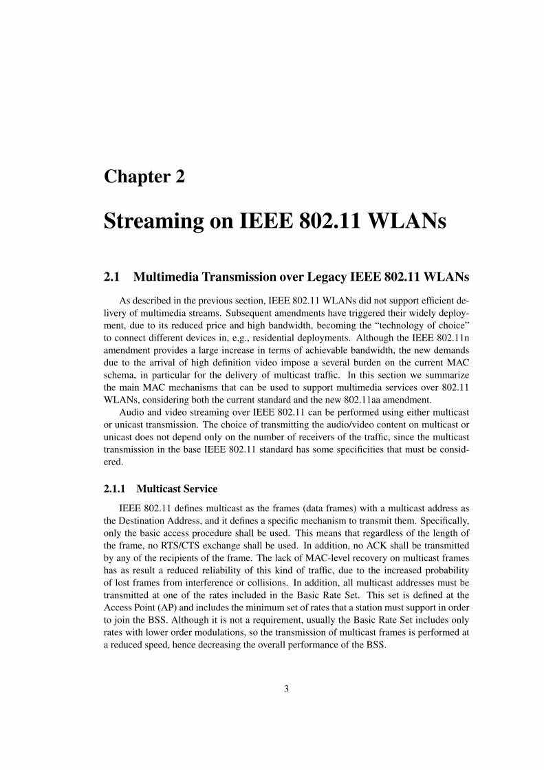
The IEEE 802.11 standard for Wireless LAN (WLAN) [3] has become one of the mostcommon technologies to provide broadband connectivity to the Internet. The widespread de-ployment of high-rate access points (APs), with modulation schema reaching up to 150 Mbpsas defined by the amendment 802.11n [4] is enabling the introduction of applications withrelatively large bandwidth demands, like e.g., YouTube, Skype videoconferencing or Vide-oLAN video-streaming.
The original 802.11 standard was poorly suited for the efficient support of multimediaflows, and in particular video streams, because of several reasons: i) the originally supportedphysical transmission rates (1 and 2 Mbps) imposed a severe bottleneck on the maximumachievable rate, regardless of the efficiency of the MAC protocol; ii) only “best-effort” ser-vice was supported, thus preventing any sort of traffic differentiation that could improve theperformance of multimedia applications, which as compared to data can relax their reliabil-ity requirements below 100 % to improve performance; iii) multicast transmissions werevery inefficient and unreliable (as widely reported in various works, see e.g. [11]), whicheventually prevented its use on WLANs, as there is no proper support for video streaming tovarious receivers.
The subsequents amendments to the 802.11 standard have lessen the first two limitations.Indeed, as already mentioned, the introduction of PHY-amendments have boosted the max-imum achievable rates, starting with the 802.11b [1] that increased the maximum rate up to11 Mbps, continuing with the 802.11a and 802.11g amendments that reach up to 54 Mbps,and finally with the 802.11n [4] which specifies modulation rates up to 600 Mbps when us-ing four spatial streams of 150 Mbps. On the other hand, the 802.11e amendment [2] hasintroduced traffic differentiation via the setting of the contention parameters, thus enablingboth the ability to prioritize one type of traffic over other type [7] and a more efficient oper-ation of WLANs by proper tuning of the MAC parameters [15]. The remaining challenge,therefore, is to efficiently support multicast over 802.11 WLANs.
The IEEE 802.11aa Task Group is addressing the multicast limitation, with the defini-tion of the mechanisms to support “Robust streaming of Audio Video Transport Streams”.Its focus is therefore to extend the base 802.11 standard with those mechanisms that improveperformance of multimedia streaming over WLAN. In particular, as we will describe in Sec-tion 2 and validate via models and simulations in Sections 3 and 4, the new mechanismstarget at significantly improving both the effectiveness and efficiency of multicast, allowing
1

2 Chapter 1. Introduction
for a fine-grained control of the type of service provided to video traffic.In this thesis, we present a model and simulation-based evaluation of the mechanisms
defined in the current version of the standard, in order to assess their performance in a mixedscenario with video streams and data traffic. We quantify the throughput and the reliabil-ity that each of the considered mechanisms provides to a video stream for different numberof receivers as well as the efficiency in terms of the bandwidth that is left for data users.Our results show that: i) indeed the new defined mechanisms substantially enrich the set ofservices than can be offered to multimedia streams in 802.11 WLANs; ii) there is no clear“winner” as each of them offers different trade-offs between efficiency, reliability and com-plexity, depending on the considered scenario.
The rest of the thesis is organized as follows. In Section 2, we provide a short summaryof the different mechanisms that can be used to transport multimedia traffic over 802.11WLANs, considering both the existing mechanisms as defined in the current standard andthe new mechanisms being discussed within TGaa. In Section 3, we present the analyti-cal models developed to study the throughput of the new multicast mechanisms in a mixedWLAN scenario under saturation conditions. In Section 4 we validate the models for thethroughput via simulation and we study the reliability of each mechanism also via simula-tion. Finally, in Section 5 we summarize the main results and we describe the future lines ofresearch.
Chapter 2
Streaming on IEEE 802.11 WLANs
2.1 Multimedia Transmission over Legacy IEEE 802.11 WLANs
As described in the previous section, IEEE 802.11 WLANs did not support efficient de-livery of multimedia streams. Subsequent amendments have triggered their widely deploy-ment, due to its reduced price and high bandwidth, becoming the “technology of choice”to connect different devices in, e.g., residential deployments. Although the IEEE 802.11namendment provides a large increase in terms of achievable bandwidth, the new demandsdue to the arrival of high definition video impose a several burden on the current MACschema, in particular for the delivery of multicast traffic. In this section we summarizethe main MAC mechanisms that can be used to support multimedia services over 802.11WLANs, considering both the current standard and the new 802.11aa amendment.
Audio and video streaming over IEEE 802.11 can be performed using either multicastor unicast transmission. The choice of transmitting the audio/video content on multicast orunicast does not depend only on the number of receivers of the traffic, since the multicasttransmission in the base IEEE 802.11 standard has some specificities that must be consid-ered.
2.1.1 Multicast Service
IEEE 802.11 defines multicast as the frames (data frames) with a multicast address asthe Destination Address, and it defines a specific mechanism to transmit them. Specifically,only the basic access procedure shall be used. This means that regardless of the length ofthe frame, no RTS/CTS exchange shall be used. In addition, no ACK shall be transmittedby any of the recipients of the frame. The lack of MAC-level recovery on multicast frameshas as result a reduced reliability of this kind of traffic, due to the increased probabilityof lost frames from interference or collisions. In addition, all multicast addresses must betransmitted at one of the rates included in the Basic Rate Set. This set is defined at theAccess Point (AP) and includes the minimum set of rates that a station must support in orderto join the BSS. Although it is not a requirement, usually the Basic Rate Set includes onlyrates with lower order modulations, so the transmission of multicast frames is performed ata reduced speed, hence decreasing the overall performance of the BSS.
3

4 Chapter 2. Streaming on IEEE 802.11 WLANs
2.1.2 Unicast Service
The second choice for transmitting audio/video frames is the use of unicast traffic. Un-like multicast, unicast traffic can be transmitted at any rate and it is acknowledged, so itsreliability is higher than standard multicast traffic. The counterpart is that the bandwidthand delay required to transmit the same flow to multiple receivers grow with the number ofstations receiving it. Hence, it is only feasible for low bit rate flows and a reduced numberof receiving stations.
2.1.3 Prioritization
With the latest additions regarding QoS to the standard, unicast and multicast traffic canbe differentiated and prioritized, so regardless of its transmission on unicast or multicast, thenetwork can be configured so multimedia flows can receive some advantage while accessingthe medium compared with the rest of traffic. Although this is clearly an advantage, oneof the problems already identified with this approach is the definition of only one queuefor video traffic. Current codecs do not generate equal frames, being some of them moreimportant than others. A better solution would be to allow traffic differentiation within thevideo flow, which is a mechanism adopted in the new extensions that we address in the nextsection.
2.2 MAC Enhancements for Robust Audio Video Streaming:IEEE 802.11aa
PktPkt PktPkt
Pkt
Pkt Pkt
Pkt
Pkt
AAC_VO AC_VO AAC_VI AC_VI AC_BE AC_BK
Mapping to Access Category
VO VI BE BK
Data Packet, Traffic Class
Transmit queue for Access Category
EDCA functions
Introduced in IEEE 802.11aa
Figure 2.1: Stream Classification Service over the standard EDCA mechanism.
As explained in the previous section, the availability of mechanisms to perform video

5 Chapter 2. Streaming on IEEE 802.11 WLANs
streaming over 802.11 WLANs is rather limited. The upcoming IEEE 802.11aa amendmentis being designed to specifically address the challenge of multimedia transmission, imple-menting a set of new functionalities over the base specification. In this section, we describethe main extensions to the IEEE 802.11 standard as defined in the 802.11aa Draft 6.0 [5].The objective of these extensions is to efficiently improve the reliability of audio and videostreaming, while maintaining and even improving the service as perceived by the otherstreams. The amendment also specifies related functionality (e.g., OBSS management, inter-working with IEEE 802.1AVB) but we only consider the case of a single WLAN. Followingthis, we consider the following two mechanisms:
• Stream Classification Service (SCS).
• Groupcast with Retries (GCR) service.
In the following we present these new functionalities.
2.2.1 Stream Classification Service
This service is built over the EDCA access mechanism which is based on different ac-cess categories (ACs) and supports traffic differentiation by means of priorities betweenqueues and heterogeneous configuration of the contention parameters (namely AIFS, CWand TXOP ). The SCS, along with the intra-Access Category (AC) Traffic Stream (TS)prioritization, enables classification using layer 2 and/or layer 3 signaling and increases thegranularity of the service differentiation already provided by the EDCA mechanism.
More specifically, as illustrated in Fig. 2.1, this service introduces two additional queueswithin the existing EDCA access categories: one additional queue for audio (AAC VO) andanother one for video (AAC VI), in order to support prioritization within the video flows.Furthermore, in addition to this intra AC prioritization, packets are tagged with their dropeligibility indicator (DEI), which defines a different maximum number of (short and long)retries.
With this availability of additional access categories and the drop eligibility bit, gracefuldegradation of video quality is supported in case of bandwidth shortage. However, it shouldbe noted that the SCS does not alter the standard MAC behavior, as it builds on the existingEDCA mechanism. Therefore, it inherits the same limitations of the EDCA mechanismwith respect to video streaming, being either i) extremely unreliable, in case of multicast, orii) extremely inefficient, in case of unicast transmissions to a moderate number of receivers(as we will see in the next section).
2.2.2 Groupcast with Retries Service
Two of the main weaknesses of the use of multicast in existing 802.11 WLANs, asdescribed in Section 2.1.1 are: i) the poor reliability of the service, since multicast framesare not acknowledged, and ii) the high inefficiency due to the use of a low modulation codingscheme, as it uses the largest rate available in the Basic Rate Set. In order to overcome theselimitations, the IEEE 802.11aa draft standard proposes several new mechanisms to improvethe performance and efficiency of the delivery of frames addressed to a group of stations.This way, in addition to the legacy multicast service (that we denote as “No-Ack/No-Retry”

6 Chapter 2. Streaming on IEEE 802.11 WLANs
Busy medium
DIFS
Video frame1
DIFS
Video frame2
DIFS
Video frame3No-Ack/No-Retry
Busy medium
DIFS
Video frame1
DIFS
Video frame1
DIFS
Video frame1
GCR Unsolicited
Retries
DIFS
Video frame4
DIFS
Video frame2
Busy medium
DIFS
Video frame1
SIFS
DMS
ACK
DIFS
Video frame1
SIFS
ACK
DIFS
Video frame2
SIFS
ACK
GCR group member 1 is addressed GCR group member 2 is addressed GCR group member 1 is addressed
1st UR is transmitted 2nd UR is transmitted
Busy medium
DIFS
Video frame1
SIFSGCR
BlockAck
SIFS DIFS
Video frame2 Video frame3
SIFS
BlockAckRequest
SIFS
BlockAck
BlockAckRequest
SIFS
BlockAck
SIFS
GCR group member 1
GCR group member 2
a)
b)
c)
d)
Backoff
Figure 2.2: Available mechanisms with the Groupcast with Retries Service (GCR).
in Fig. 2.2), the IEEE 802.11aa specifies the following new mechanisms (illustrated in thesame Figure):
• GCR Unsolicited Retry. This delivery method preemptively retransmits a frame oneor more times (up to a certain lifetime limit), to increase the delivery probability atthe STAs (see Fig. 2.2b). The retransmission of these frames is implementation-dependent. This way, the mechanism aims at improving the reliability of the legacymulticast without introducing the associated overhead of an acknowledgement mech-anism.
• Directed Multicast Service (DMS). This mechanism basically consists on the con-version multicast to unicast (as illustrated in Fig. 2.2c for two groupcast members).This way, those frames transmitted to a multicast address are individually transmittedto each of the associated STAs that joined the multicast group. The individually ad-dressed frames will therefore be retransmitted until an ACK is received at the AP, orthe retransmission count limit is exceeded (in which case the frame is discarded). Itis clear to see that, although this mechanism provides very high reliability, has largescalability constrains as the required throughput increase with the number of groupmembers. Note that this mechanism was first introduced in IEEE 802.11v [6] andextended to target with groupcast addressed frames.
• GCR Block Ack. This mechanism extends the Block Ack mechanism already definedin the current version of the standard to account for group addressed frames. Whilewith the previous mechanism the sender transmitted a burst of data frames and thenexplicitly requested an ACK to the receiving station, in this case is the AP or orig-inator the one that, after transmitting no more than GCR buffer size frames to theGCR group address, sends a BlockAckRequest frame to one of the destination STAsor recipients. After receiving the BlockAck from this STA, the AP may send anotherBlockAckRequest to another STA belonging to the same group of receiving station (themechanism is also illustrated in Fig. 2.2d).There are two possible Block Ack mechanisms:

7 Chapter 2. Streaming on IEEE 802.11 WLANs
– Immediate Block Ack
– Delayed Block Ack
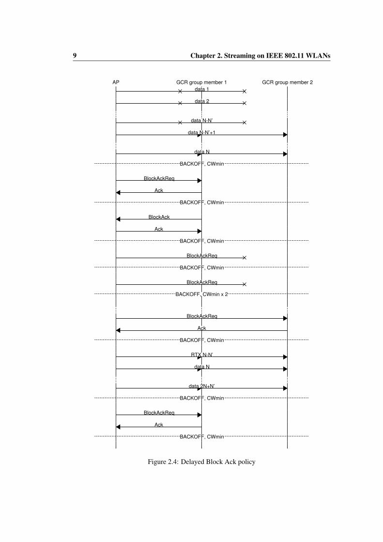
The recipient of a BlockAckRequest replies immediately (after a SIFS time) with aBlockAck frame. In contrast, in the Delayed Block Ack, after receiving a BlockAck-Request the recipient starts a backoff process before sending the BlockAck frame.With the Delayed Block Ack, both the BlockAckRequest and the BlockAck framesare acknowledged with an ACK frame. In the following we describe the operationof each of these two mechanisms with further detail, illustrating it with Message Se-quence Charts (MSCs).Figure 2.3 shows a frame exchange example in which the AP transmits to the GCRgroup formed by two video stations a burst of N video frames using the GCR Im-mediate Block Ack mechanism. N ′ out of the N frames will collide and will beretransmitted. In case of the control frames, BlockAckReq frames will be retransmit-ted after a DIFS if no BlockAck for the corresponding GCR group member is receivedafter a SIFS interval. A backoff will occur only after the BlockAckReq and BlockAckframe exchange always with the minimum contention window CWmin and a maxi-mum backoff stage m = 0. Figure 2.4 shows the MSC for the same previous scenariobut using GCR Delayed Block Ack policy. We can see that backoff is performed aftera burst transmission with CWmin and m = 0, and after every BlockAckReq-Ack orBlockAck-Ack with CWmin and m 6= 0 .
Note that the draft proposes these mechanisms but no setting of the parameters or guide-lines are provided in order to pick the most efficient one for a given scenario. This is themain motivation of this thesis which we tackle in the next section. We will provide a per-formance assessment of each of the mechanisms from the GCR service in order to properlyunderstand their benefits and limitations.
2.3 Related Work
The analysis presented in this thesis is more related to the modeling of the mechanismsdescribed in the IEEE 802.11aa Draft than to the video transmission over WLAN. Morespecifically, we have based our research in the analytical model for DCF presented in [9] aswell as in the analysis of EDCA in [7] which adds QoS capabilities that allow the prioritiza-tion between different types of traffic, like e.g., data and video. Additionally, due to the poorperformance of legacy IEEE 802.11 multicast, other mechanisms have been proposed in theliterature to improve it. In [12] a leader-based ACK mechanism is proposed in which the ac-knowledgments are performed only by the receiver station with the weakest link. And in [8]a network coding approach is proposed to improve multicast error control on WLAN. Themain drawback of these proposals is that they require changes in the physical layer of thecurrent MAC making difficult its deployment as well as the coexistence with legacy IEEE802.11.

8 Chapter 2. Streaming on IEEE 802.11 WLANs
AP GCR group member 1 GCR group member 2
data 1
data 2
data N-N’
data N-N’+1
data N
BlockAckReq
BlockAckReq
BlockAckReq
BlockAck
BlockAckReq
BlockAck
BACKOFF CWmin
RTX data 1
RTX N-N’
data N+1
data 2N-N’
BlockAckReq
BlockAck
BlockAckReq
BlockAck
BACKOFF CWmin
Figure 2.3: Immediate Block Ack policy with video and control frame recovery
9 Chapter 2. Streaming on IEEE 802.11 WLANs
AP GCR group member 1 GCR group member 2
data 1
data 2
data N-N’
data N-N’+1
data N
BACKOFF, CWmin
BlockAckReq
Ack
BACKOFF, CWmin
BlockAck
Ack
BACKOFF, CWmin
BlockAckReq
BACKOFF, CWmin
BlockAckReq
BACKOFF, CWmin x 2
BlockAckReq
Ack
BACKOFF, CWmin
RTX N-N’
data N
data 2N+N’
BACKOFF, CWmin
BlockAckReq
Ack
BACKOFF, CWmin
Figure 2.4: Delayed Block Ack policy

Chapter 3
Performance Analysis
In this section we analyse the throughput of the legacy No-Ack/No-Retry and the newmulticast mechanisms under specification in the IEEE 802.11aa Draft. Our analysis buildson the widely used work of [9] and assumes that the reader is familiarized with it.
3.1 Scenario and Assumptions
AP
Nv
Nrx Nd
τv
τd τd
τd
Figure 3.1: Considered scenario
We describe the assumptions and the scenario shown in Figure 3.1 upon we will rely for ouranalysis:
• We consider two types of traffic:
– Video traffic which is generated in saturation by Nv video stations using one ofthe multicast mechanisms that are the object of analysis. It is addressed towardsa variable number of video receivers Nrx. In Figure 3.1, Nv is particularized ina single AP.
– Data traffic which is generated towards the AP by a variable number of stationsNd in saturation conditions and using the DCF mode.
10
11 Chapter 3. Performance Analysis
• Nrx are the video receiver stations that form the GCR group and are the recipients ofthe multicast traffic sent by the AP.
• We have ideal channel conditions, i.e., an error-free channel in which the only sourcesof packet losses are collisions between stations, i.e., two or more stations access thechannel simultaneously.
• We differentiate between video collisions – video frames collide with other video ordata frames – and data collisions – data frames collide with other data frames.
• The collision probabilities for video pcv and data pcd are independent of the backoffstage but they are functions of the transmission probabilities for video τv and data τd.
3.2 No-Ack/No-Retry Model
3.2.1 Throughput analysis
In this section we compute the throughput of data stations rd and video stations rvwhen video stations transmit using No-Ack/No-Retry multicast mode. Those throughputsare function of τd and τv which are the probabilities that data stations and video stationstransmit in a randomly chosen slot time, as well as of Nd and Nv and can be computed as:
rd =PsdLd
Tslot(3.1)
rv =PsvLv
Tslot(3.2)
where Psd and Psv are the probabilities that a random slot time contains a succesful data orvideo transmission respectively, Ld and Lv are the length of the data and video frames, andTslot is the total slot time duration which is computed as:
Tslot = PsdTsd + PcdTcd + PsvTsv + PcvTcv + PeTe (3.3)
Pcd , Pcv and Pe are the probabilities that a random slot time contains a data collision, a videocollision or an empty slot respectively and, Tcd , Tcv and Te the slot time duration in eachcase. Using No-Ack/No-Retry the slot times can be computed as:
Tsd = TPLCP +H
Rd+Ld
Rd+ SIFS + TPLCP +
ACK
Rc+DIFS (3.4)
Tcd = TPLCP +H
Rd+Ld
Rd+DIFS (3.5)
Tsv = Tcv = TPLCP +H
Rv+Lv
Rv+DIFS (3.6)
where TPLCP is the Physical Layer Convergence Protocol (PLCP) preamble, H is the MACheader plus the Frame Check Sequence (FCS) length, ACK is the length of the Ack frameand, Rd, Rv and Rc are the channel bit rate for data, video and control frames respectively.We note that No-Ack/No-Retry multicast uses for Rv one of the Basic Service Set.

12 Chapter 3. Performance Analysis
We denote pcv as the probability that a video transmission attempt collides 1 . Therefore,the probability of not colliding occurs when none of theNd data stations nor the otherNv−1video stations are transmitting and can be expressed as:
(1− pcv) = (1− τd)Nd (1− τv)Nv−1 (3.7)
With the above, the probability psv that a video transmission attempt is successful can becomputed as:
psv = τv (1− pcv) = τv (1− τd)Nd (1− τv)Nv−1 (3.8)
For all the Nv video stations, the probability that a random slot contains a successful videotransmission is:
Psv = Nv psv = Nv τv (1− τd)Nd (1− τv)Nv−1 (3.9)
Similarly, if pcd is the probabililty that a data transmission attempt collides then theprobability of not colliding occurs when none of the other Nd−1 data stations nor the Nv
video stations are transmitting:
(1− pcd) = (1− τd)Nd−1 (1− τv)Nv (3.10)
and the probability psd that a data transmission attempt is successful can be computed as:
psd = τd (1− pcd) = τd (1− τd)Nd−1 (1− τv)Nv (3.11)
For all the Nd data stations, the probability that a random slot contains a successful datatransmission is:
Psd = Nd psd = Nd τd (1− τd)Nd−1 (1− τv)Nv (3.12)
Now, if in Pcd we only account for slots that contain collisions between data transmissions(crossed data and video collisions will be accounted in Pcv ) we can compute:
Pcd = (1− τv)Nv
[1−
(Pe
(1− τv)Nv+
Psd
(1− τv)Nv
)]= (1− τv)Nv
[1− (1− τd)Nd −Nd τd (1− τd)Nd−1
] (3.13)
where we have employed that the probability Pe of an empty slot occurs when there are nodata nor video transmissions:
Pe = (1− τd)Nd (1− τv)Nv (3.14)
Finally, the probability Pc that a random slot contains a collision can be expressed as:
Pc = Pcd + Pcv = 1− (Psd + Psv + Pe) (3.15)
and from the above we can obtain Pcv as:
Pcv = 1− Psd − Pcd − Psv − Pe (3.16)
1pcv represents a different event and should not be confused with Pcv defined before. While the former refersto the conditional probability that an attempt collides, the latter refers to the probability that there is a collisionin a randomly chosen slot time.

13 Chapter 3. Performance Analysis
3.2.2 Analysis of the τ
In order to compute τd and τv we have to consider that:
• Data is sent in saturation using DCF so τd can be computed according to [9] for eachnumber of data stations Nd, using a minimum contention window CWmind
and amaximum backoff stage md.
τd =2 (1− 2pcd)
(1− 2pcd) (CWmind+ 1) + pcdCWmind
[1− (2pcd)md ]
(3.17)
• Video is sent in saturation using No-Ack/No-Retry multicast which in terms ofthroughput can also be modeled with [9] as a DCF in which no exponential backoff isused: mv = 0. Under these conditions, τv can be computed as:
τv =2
CWminv + 1(3.18)
3.3 GCR Unsolicited Retry Model
In this section, the Nv video stations are transmitting video using GCR UnsolicitedRetry. Employing this mechanism for any number of retries R, the probability psv that avideo transmission attempt is successful can be computed as:
psv = τv (1− pcv)R∑i=0
1
(R+ 1)picv =
τv(1− pR+1
cv
)R+ 1
(3.19)
which considers that a video transmission contains useful data for the throughput when (i)it does not collide, and (ii) all previous transmissions with the same content have collided.Note that the latter depends on the number of previous retransmissions, which is uniformlydistributed between 0 and R (each case with probability 1/(R + 1)). We can see that theprevious No-Ack/No-Retry mechanism is the special case for which R = 0.
The probability psd that a data transmission attempt is successful does not change withrespect to the case of No-Ack/No-Retry because a data station does not distinguish betweenthe first video transmission or any of the retries that follow which makes τd and τv are equalto the previous case. However, the time slots Tsv and Tcv using GCR UR, have changedsince now video is sent at the same rate than data traffic: Rv = Rd.Employing psv from equation 3.19 in the equations for the No-Ack/No-Retry model we canobtain the throughput for data and video stations when using GCR-UR mechanism.
3.4 GCR Directed Multicast Model
3.4.1 Throughput analysis
In this section, Nv video stations are transmitting video towards Nrx receiver stationseach using GCR Directed Multicast. For each of the receivers we will have a unicast flow ofvideo transmitting in saturation in DCF mode and hence, it can be studied following [9].

14 Chapter 3. Performance Analysis
The throughput analysis for data traffic is the same as for No-Ack/No-Retry but for videotraffic it has to be updated to account for the video flow to each receiver station as well forthe new time slot durations. The throughput of video rvDMS can be computed as:
rvDMS =1
Nrx
PsvLv
Tslot(3.20)
considering that every video receiver will be served periodically with a video transmissionafter serving the rest of video receivers. The time slots for video using GCR DMS are now:
Tcv = TPLCP +H
Rv+Lv
Rv+DIFS (3.21)
andTsv = TPLCP +
H
Rv+Lv
Rv+ SIFS + TPLCP +
ACK
Rc+DIFS (3.22)
3.4.2 Analysis of the τ
GCR DMS performs a conversion multicast to unicast which employs the DCF mode.Therefore, we can directly apply the results of [9] to video traffic. For data traffic τd can becomputed with equation (3.17) and, for video traffic using a minimum contention windowCWminv and a maximum backoff stage mv, τv can be computed for a video flow as:
τv =2 (1− 2pcv)
(1− 2pcv) (CWminv + 1) + pcvCWminv [1− (2pcv)mv ]
(3.23)
3.5 GCR Immediate Block Ack Model
3.5.1 Throughput Analysis
In this section, the Nv video station will transmit to the GCR group formed by the Nrx
video stations a burst of N video frames using the GCR Immediate Block Ack mecha-nism. For simplicity reasons, in this and the next section we assume a single video source,Nv = 1, although the analysis could be easily extended to the case with multiple videosources. When colliding with a data frame, the first N ′ video frames which overlap withthe data transmission will be lost, while the remaining N-N’ video frames will be receivedsuccessfully. According to that, psv accounts for the average number of successful videoframes transmitted in a slot time:
psv = τv[(1− pcv)N + pcv
(N −N ′
)](3.24)
where following the explanation above, a burst transmits N successful frames in absence ofcollisions and N-N’ otherwise. Therefore, the video throughput is:
rviback =τv [(1− pcv)N + pcv (N −N ′)] Lv
Tslot(3.25)
15 Chapter 3. Performance Analysis
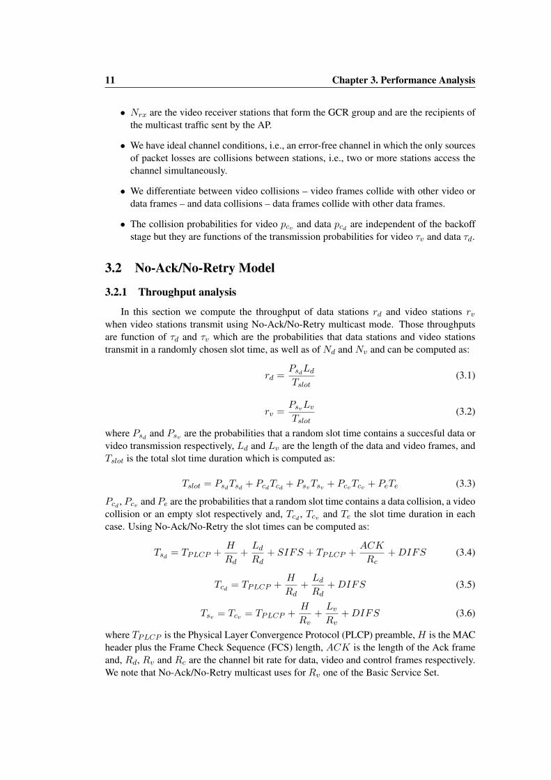
where the slot durations for video transmission need to be updated in Tslot as follows:
Tsv = Tcv =N
(TPLCP +
H
Rv+Lv
Rv+ SIFS
)+ 2Nrx
(TPLCP +
BACK
Rc
)+ (2Nrx − 1)SIFS +DIFS
(3.26)
where BACK is the length of a BlockAckReq or a BlockAck.Data throughput and τv are the same than the computed for the No-Ack/No-Retry model aswe are using CWminv and mv = 0.
3.6 GCR Delayed Block Ack Model
3.6.1 Throughput analysis
In this section, bursts of N video frames are sent using the GCR Delayed Block Ackmechanism. According to that, a video source station and its Nrx receivers can be modeledas a unique virtual video station. For every video burst transmitted, the virtual station sendsa BlockAckRequest and a BlockAck to each of the video receivers (a total of 2Nrx controlframes) in case no collision occur. Only in the case that a collision occurs in one of thecontrol frames, the virtual station doubles its CWv.
• If we denote pb the probability that the virtual station transmission attempt contains aburst then:
pb =1
1 +2Nrx
1− pcv
(3.27)
• Otherwise, the virtual station transmission attempt will contain a control frame withprobability: 1− pb
With the above, the probability psv that a burst transmission attempt is successful can becomputed as:
psv = τv pb[(1− pcv)N + pcv
(N −N ′
)](3.28)
and the video throughput is:
rvdback =τv pb [(1− pcv)N + pcv (N −N ′)] Lv
Tslot(3.29)
where Tslot needs to be updated to account for the two types of video transmissions, burstsof N frames and control frames:
Tslot = PsdTsd+PcdTcd+τv pbTNframes+τv (1− pb) (1− pcv)TBlockAcks+PeTe (3.30)
where:
TNframes= N
(TPLCP +
H
Rv+Lv
Rv+ SIFS
)+DIFS (3.31)
TBlockAcks = TPLCP +BACK
Rc+ SIFS + TPLCP +
ACK
Rc+DIFS (3.32)

16 Chapter 3. Performance Analysis
0 1 2 i
1-τv,o(1-pb)τv,o(1-pb)pcv
(1-τv,1) (1-τv,2)
τv,1 pcv τv,2 pcv
τv,2 (1-pcv)τv,1 (1-pcv) τv,i (1-pcv)
(1-τv,i)
τv,i pcv
Figure 3.2: Markov chain model of the virtual video station.
3.6.2 Analysis of the τ
While in the previous cases the computation of τ followed the analysis of [9] with minorvariations, the main difference of this case with the previous cases is that the CWv is notalways doubled after a failed attempt. In particular, after the transmission of a video burst,the next attempt which will be a BlockAckReq will use CWminv independently of whetherthe video burst transmission collided or not. In the following, we provide an analysis of τthat accounts for this behavior. As extending the Markov chain of [9] with this would resultin a very complex Markov chain, we follow use a different and novel Markov chain witha much smaller number of states. Figure 3.2 models the backoff stage of the virtual videostation with a discrete Markov chain which accounts for the number of collisions sufferedby the control frames: BlockAckReq or BlockAck frames.At state 0 the virtual station transmits in the next slot with probability:
τv,0 =2
CWminv + 1(3.33)
in case the transmission attempt is not a control frame, the station remains at stage 0. Other-wise, if it is a control frame that suffers a collision, the station doubles its CWv and movesto the next state. At next stages: (i) if it does not transmit, it remains in that state; (ii) if thetransmission is succesful, it moves to stage 0 and resets its CWv; (iii) if the transmissioncollides, it doubles the CWv and moves to the next stage.In general, at state i the transmission probability can be approximated using [7]:
τv,i ≈τv,02i
(3.34)
If we denote pi the probability of being at stage i, τv can be computed as the average:
τv =∞∑i=0
τv,i pi (3.35)

17 Chapter 3. Performance Analysis
In a discrete Markov chain the probability of being at a stage is a function of the prob-ability of being at the previous stage and the transition probabilities so the probability p1 ofbeing at backoff stage 1 is the probability that being at stage 0 the video station transmitsa control frame that collides, plus the probability that being already at stage 1, the videostation does not transmit:
p1 = p0 τv,0 (1− pb) pcv + p1 (1− τv,1) (3.36)
using equation (3.34) we can write:
p1 = 2pcv (1− pb) p0 (3.37)
similarly for p2:p2 = p1 τv,1 pcv + p2 (1− τv,2) (3.38)
using equations (3.34) and (3.37) we can write:
p2 = 2pcvp1 = (2pcv)2 (1− pb) p0 (3.39)
so at stage i:pi = (2pcv)
i (1− pb) p0 (3.40)
Applying the normalization condition:∞∑i=0
pi = 1 then:
p0 +
∞∑i=1
(2pcv)i (1− pb) p0 = 1 (3.41)
which yields:
p0
(1 +
2pcv1− 2pcv
(1− pb))
= 1 (3.42)
and gives:
p0 =1− 2pcv1− 2pcvpb
(3.43)
from equations (3.35) and (3.40):
τv = τv,0 p0 +∞∑i=1
τv,02i
(2pcv)i (1− pb) p0 = τv,0 p0
(1− pcvpb1− pcv
)(3.44)
finally, substituting τv and p0:
τv =
(2
CWminv + 1
)(1− 2pcv1− 2pcvpb
)(1− pcvpb1− pcv
)(3.45)
In the case of data stations, their transmission probability τd is still given by [9]:
τd =2 (1− 2pcd)
(1− 2pcd) (CWmind+ 1) + pcdCWmind
[1− (2pcd)md ]
(3.46)
Therefore to find τd and τv we need to solve the system of non-linear equations formed byequations (3.45 ) and (3.46 ).

Chapter 4
Performance Evaluation
In order to perform the evaluation of the proposed models for the throughput of the newmulticast mechanisms under specification in the IEEE 802.11aa draft, we have extended oursimulation tool used in [13, 14]. This is a C/C++ discrete event simulator that accuratelymodels the behavior of the IEEE 802.11g MAC layer. Additionally, we have also analyzedthe reliability of each mechanism in the same scenario under more realistic constraints.We show that our simulation results closely match those obtained analytically which vali-dates the analysis presented in the previous section.
4.1 Throughput Performance
For the validation of the theoretical models we have particularized the scenario describedin Figure 3.1 with:
• Nv = 1 video station is an AP that transmits video in saturation towards the variablenumber of receivers Nrx.
• Nd = 1, 4, 7, 10, 13 and 16 data stations transmit in saturation with a modulationrate of 54 Mbps while control frames (ACKs) are sent at 6 Mbps, packet length is1500 bytes, CWmind
= 31 and md = 5.
• For every Nd we perform a sweep on the number of video receiver stations that formthe GCR group Nrx from 1 to 16 stations.
4.1.1 No-Ack/No-Retry
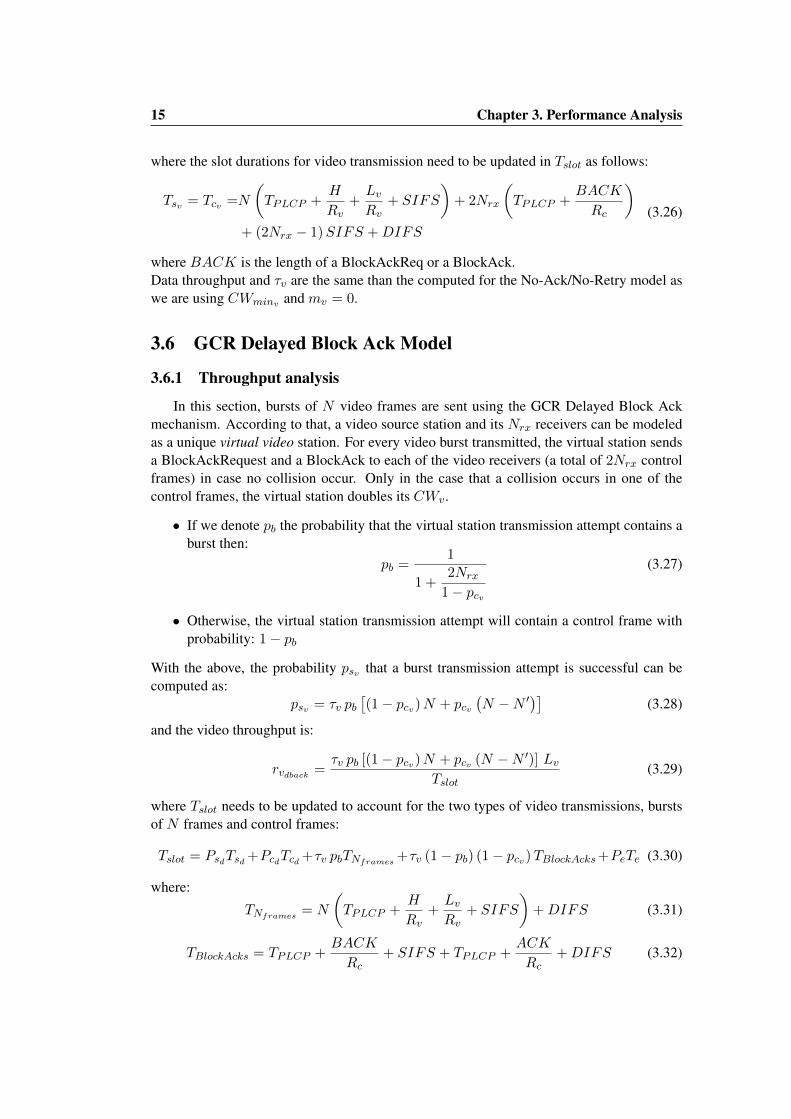
The legacy multicast service is generating saturation video traffic with a modulation rateof 6 Mbps with packets of Lv = 1500 bytes, CWminv = 31 and mv = 0. Figure 4.1 showsthe data throughput obtained with the analytical model and the simulations and Figure 4.2shows it for the video throughput. We can note that in both cases, the throughput doesnot depend on the number of receiver stations but on the number of data stations, as No-Ack/No-Retry legacy multicast does not interact at all with the receiving stations. Althoughthe No-Ack/No-Retry mechanism only transmits once each video frame, this transmissionis done at 6 Mbps against the 54 Mbps of the data, which –according to the performanceanomaly [10]– substantially reduces the throughput much below 54 Mbps.
18

19 Chapter 4. Performance Evaluation
0
5
10
15
20
25
30
1 2 3 4 5 6 7 8 9 10 11 12 13 14 15 16
Dat
a T
hro
ug
hp
ut
(Mb
ps)
Number of video receivers
Analysis, Nd=1(sim)
Analysis, Nd=4(sim)
Analysis, Nd=7(sim)
Analysis, Nd=10(sim)
Analysis, Nd=13(sim)
Analysis, Nd=16(sim)
Figure 4.1: Data throughput using No-Ack/No-Retry
0
5
10
15
20
25
30
1 2 3 4 5 6 7 8 9 10 11 12 13 14 15 16
Vid
eo T
hro
ug
hp
ut
(Mb
ps)
Number of video receivers
Analysis, Nd=1(sim)
Analysis, Nd=4(sim)
Analysis, Nd=7(sim)
Analysis, Nd=10(sim)
Analysis, Nd=13(sim)
Analysis, Nd=16(sim)
Figure 4.2: Video throughput using No-Ack/No-Retry

20 Chapter 4. Performance Evaluation
4.1.2 GCR Unsolicited Retry
To analyze the GCR Unsolicited Retry mode, we consider a scenario with Nv = 1 videostation generating saturation video traffic with a modulation rate of 54 Mbps, packets ofLv = 1500 bytes, CWminv = 31 and mv = 0. Figure 4.3 shows the data throughput forthe analytical model and the simulations using GCR Unsolicited Retry for R=8 unsolicitedretries and Figure 4.4 shows the video throughput. As in the No-Ack/No-Retry case, thethroughput using GCR UR does not depend on the number of receiver stations. The use ofa higher modulation coding scheme improves the data throughput up to around 25 Mbps.However, the overhead introduced by the GCR UR decreases the video performance as eachframe is sent 9 times even if it has been already correctly transmitted.
0
5
10
15
20
25
30
1 2 3 4 5 6 7 8 9 10 11 12 13 14 15 16
Dat
a T
hro
ug
hp
ut
(Mb
ps)
Number of video receivers
Analysis, Nd=1(sim)
Analysis, Nd=4(sim)
Analysis, Nd=7(sim)
Analysis, Nd=10(sim)
Analysis, Nd=13(sim)
Analysis, Nd=16(sim)
Figure 4.3: Data throughput using GCR Unsolicited Retries
21 Chapter 4. Performance Evaluation
0
5
10
15
20
25
30
1 2 3 4 5 6 7 8 9 10 11 12 13 14 15 16
Vid
eo T
hro
ug
hp
ut
(Mb
ps)
Number of video receivers
Analysis, Nd=1(sim)
Analysis, Nd=4(sim)
Analysis, Nd=7(sim)
Analysis, Nd=10(sim)
Analysis, Nd=13(sim)
Analysis, Nd=16(sim)
Figure 4.4: Video throughput using GCR Unsolicited Retries
4.1.3 GCR Directed Multicast Service
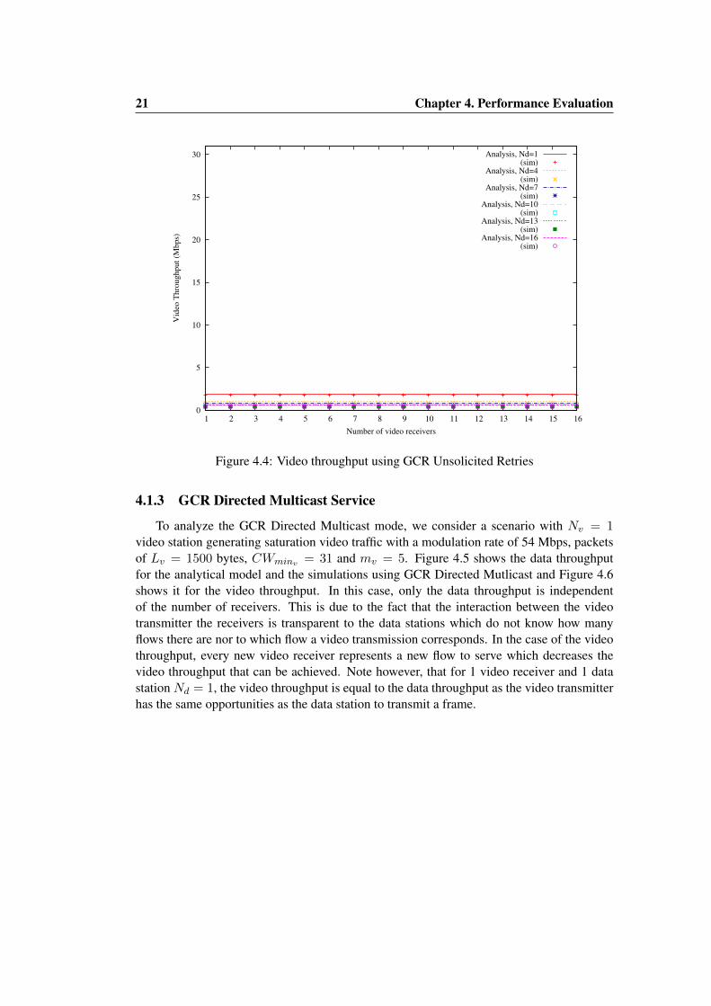
To analyze the GCR Directed Multicast mode, we consider a scenario with Nv = 1video station generating saturation video traffic with a modulation rate of 54 Mbps, packetsof Lv = 1500 bytes, CWminv = 31 and mv = 5. Figure 4.5 shows the data throughputfor the analytical model and the simulations using GCR Directed Mutlicast and Figure 4.6shows it for the video throughput. In this case, only the data throughput is independentof the number of receivers. This is due to the fact that the interaction between the videotransmitter the receivers is transparent to the data stations which do not know how manyflows there are nor to which flow a video transmission corresponds. In the case of the videothroughput, every new video receiver represents a new flow to serve which decreases thevideo throughput that can be achieved. Note however, that for 1 video receiver and 1 datastation Nd = 1, the video throughput is equal to the data throughput as the video transmitterhas the same opportunities as the data station to transmit a frame.
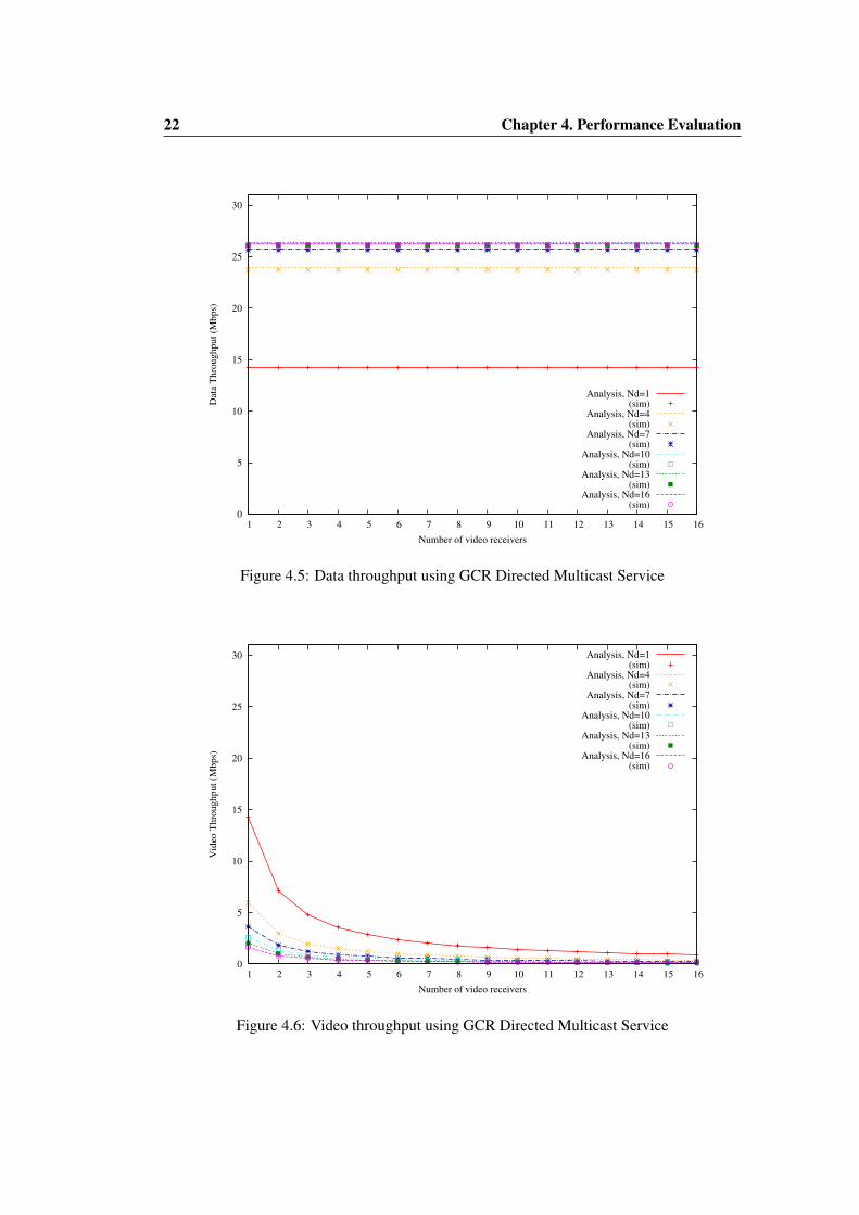
22 Chapter 4. Performance Evaluation
0
5
10
15
20
25
30
1 2 3 4 5 6 7 8 9 10 11 12 13 14 15 16
Dat
a T
hro
ug
hp
ut
(Mb
ps)
Number of video receivers
Analysis, Nd=1(sim)
Analysis, Nd=4(sim)
Analysis, Nd=7(sim)
Analysis, Nd=10(sim)
Analysis, Nd=13(sim)
Analysis, Nd=16(sim)
Figure 4.5: Data throughput using GCR Directed Multicast Service
0
5
10
15
20
25
30
1 2 3 4 5 6 7 8 9 10 11 12 13 14 15 16
Vid
eo T
hro
ug
hp
ut
(Mb
ps)
Number of video receivers
Analysis, Nd=1(sim)
Analysis, Nd=4(sim)
Analysis, Nd=7(sim)
Analysis, Nd=10(sim)
Analysis, Nd=13(sim)
Analysis, Nd=16(sim)
Figure 4.6: Video throughput using GCR Directed Multicast Service

23 Chapter 4. Performance Evaluation
4.1.4 GCR Immediate Block Ack
To analyze the GCR Immediate Block Ack mode, we consider a scenario with Nv = 1video station generating saturation video traffic with a modulation rate of 54 Mbps, packetsof Lv = 1500 bytes, CWminv = 31 and mv = 0 for the video burst and control framestransmission. Figure 4.7 shows the data throughput for the analytical model and the simu-lations using GCR Immediate BlockAck mechanism when using 5 packet bursts and Figure4.8 does it for the video throughput.In this case, both data and video throughput are affected by the number of video receiversas the more video receivers the longer the time slot and video transmission exchange. Thismechanism achieves the highest video throughput around 31 Mbps, as every successful videochannel access represents 5 packets and a collision 4 since only the first packet of the burstwould collide with a data transmission that could eventually occur only at the beginningof the same slot. However, the data throughput is severely affected as the increased lengthof transmissions reduces the amount of resources available for data traffic. Also note thatwhen the number of data stationsNd increases, the data throughput and the video throughputconverge to similar values.
0
5
10
15
20
25
30
1 2 3 4 5 6 7 8 9 10 11 12 13 14 15 16
Dat
a T
hro
ug
hp
ut
(Mb
ps)
Number of video receivers
Analysis, Nd=1(sim)
Analysis, Nd=4(sim)
Analysis, Nd=7(sim)
Analysis, Nd=10(sim)
Analysis, Nd=13(sim)
Analysis, Nd=16(sim)
Figure 4.7: Data throughput using GCR Immediate BlockAck

24 Chapter 4. Performance Evaluation
0
5
10
15
20
25
30
1 2 3 4 5 6 7 8 9 10 11 12 13 14 15 16
Vid
eo T
hro
ug
hp
ut
(Mb
ps)
Number of video receivers
Analysis, Nd=1(sim)
Analysis, Nd=4(sim)
Analysis, Nd=7(sim)
Analysis, Nd=10(sim)
Analysis, Nd=13(sim)
Analysis, Nd=16(sim)
Figure 4.8: Video throughput using GCR Immediate BlockAck
4.1.5 GCR Delayed Block Ack
To analyze the GCR Delayed Block Ack mode, we consider a scenario with Nv = 1video station generating saturation video traffic with a modulation rate of 54 Mbps withpackets of Lv = 1500 bytes, CWminv = 31, mvb = 0 for the burst transmission and forthe control frame transmission, mvback = 5. Figure 4.9 shows the data throughput for theanalytical model and the simulations using GCR Delayed BlockAck mechanism when using5 packet bursts and Figure 4.10 does it for the video throughput. This mechanism providescompletely different results than the Immediate case due to the additional backoffs that areperformed which allow the data stations to increase their throughput. We also note for thismechanism there is a slight discrepancy between the model and the simulation althoughsimulation results still follow those obtained analytically fairly well.

25 Chapter 4. Performance Evaluation
0
5
10
15
20
25
30
1 2 3 4 5 6 7 8 9 10 11 12 13 14 15 16
Dat
a T
hro
ug
hp
ut
(Mb
ps)
Number of video receivers
Analysis, Nd=1(sim)
Analysis, Nd=4(sim)
Analysis, Nd=7(sim)
Analysis, Nd=10(sim)
Analysis, Nd=13(sim)
Analysis, Nd=16(sim)
Figure 4.9: Data throughput using GCR Delayed BlockAck
0
5
10
15
20
25
30
1 2 3 4 5 6 7 8 9 10 11 12 13 14 15 16
Vid
eo T
hro
ug
hp
ut
(Mb
ps)
Number of video receivers
Analysis, Nd=1(sim)
Analysis, Nd=4(sim)
Analysis, Nd=7(sim)
Analysis, Nd=10(sim)
Analysis, Nd=13(sim)
Analysis, Nd=16(sim)
Figure 4.10: Video throughput using GCR Delayed BlockAck

26 Chapter 4. Performance Evaluation
4.2 Evaluation of the Reliability
In the previous section, we analyzed the throughput performance of the differentschemes. In this section, we focus on an additional metric of interest which is the reli-ability of the multicast mechanisms, defined as the relative number of video frames thatwere correctly received. As our analysis does not address this metric, the results presentedhereafter are limited to simulations. We consider the same scenario as for the throughputperformance. However, video traffic is not sent in saturation anymore but:
• A Constant Bit Rate (CBR) video traffic of 1 Mbps generated in the AP by creatingframe sizes of 1500 bytes every 12 ms.
• A maximum queue size in the AP of 100 frames.
4.2.1 No-Ack/No-Retry
Figure 4.11 shows the reliability when using the No-Ack/No-Retry mechanism. As ex-pected, it is not able to provide 100 % reliability even in the case of just Nd = 1, as anycollision will result in a packet lost. All losses are due to packet collisions and not to dis-carding in the queue as a 1 Mbps video is below the saturation limit for No-Ack/No-Retryshown in Figure 4.2 for any of the considered data stations. As for the throughput, thismechanism does not interact with the video receivers and so the reliability only decreaseswith the number of data traffic and remains independent of the number of video receivers.
0
10
20
30
40
50
60
70
80
90
100
1 2 3 4 5 6 7 8 9 10 11 12 13 14 15 16
Vid
eo R
elia
bil
ity
(%
)
Number of video receivers
Nd=1Nd=4Nd=7
Nd=10Nd=13Nd=16
Figure 4.11: Video reliability using No-Ack/No-Retry

27 Chapter 4. Performance Evaluation
4.2.2 GCR Unsolicited Retry
Figure 4.12 shows the reliability when using the GCR Unsolicited Retry with R = 8.The mechanism does improve the performance as compared to the legacy multicast serviceachieving 100 % reliability up to 4 data stations then decreasing to approximately 60 % for avery congested WLAN. Note that forNd = 1 andNd = 4 the video throughput in Figure 4.4is greater or equal than 1 Mbps so the performance is improved due to the use of preemptiveretransmission that lessen the impact of collisions with data stations. For more data stationshowever, the overhead introduced by the retransmissions decreases the reliability as videoframes are discarded due to queue overflow in the AP because the saturation throughput islower than the 1 Mbps video bandwidth.
0
10
20
30
40
50
60
70
80
90
100
1 2 3 4 5 6 7 8 9 10 11 12 13 14 15 16
Vid
eo R
elia
bil
ity
(%
)
Number of video receivers
Nd=1Nd=4Nd=7
Nd=10Nd=13Nd=16
Figure 4.12: Video reliability using GCR Unsolicited Retry

28 Chapter 4. Performance Evaluation
4.2.3 GCR Directed Multicast
Figure 4.13 shows the reliability when using the GCR DMS. In this case, the reliabilitydepends on the number of video receiver as this mechanism interacts with them. This mech-anism provides a reliability of 100 % when the video saturation throughput shown in Figure4.6 is bigger than the bandwidth of the transmitted video, 1 Mbps in our case. Below that,the reliability decreases as the number of data transmitters and the number of video receiversincrease due to queue overflow.
0
10
20
30
40
50
60
70
80
90
100
1 2 3 4 5 6 7 8 9 10 11 12 13 14 15 16
Vid
eo R
elia
bil
ity
(%
)
Number of video receivers
Nd=1Nd=4Nd=7
Nd=10Nd=13Nd=16
Figure 4.13: Video reliability using GCR Directed Multicast

29 Chapter 4. Performance Evaluation
4.2.4 GCR Immediate Block Ack
Figure 4.14 shows the reliability when using Immediate Block Ack with a 5 packet burst.This mechanism achieves a reliability greater than 90 % for any number of data stations andvideo receivers. In this case, as the saturation throughput shown in Figure 4.8 is alwaysabove 1 Mbps all packet losses are due to burst collisions in the channel that affect to singlepackets and not to discarding in the queue.
0
10
20
30
40
50
60
70
80
90
100
1 2 3 4 5 6 7 8 9 10 11 12 13 14 15 16
Vid
eo R
elia
bil
ity
(%
)
Number of video receivers
Nd=1Nd=4Nd=7
Nd=10Nd=13Nd=16
Figure 4.14: Video reliability using GCR Immediate Block Ack

30 Chapter 4. Performance Evaluation
4.2.5 GCR Delayed Block Ack
Figure 4.15 shows the reliability when using Delayed Block Ack with a 5 packet burst.This result is similar to the reliability of GCR DMS, for any number of data transmitters andvideo receivers, when the video bandwidth is smaller than the video throughput as shownin Figure 4.10, the reliability achieved in this case is the same as for Immediate Block Ack.However, the video bandwidth is bigger, the reliability decreases mainly because of packetdiscarding due to queue overflows.
0
10
20
30
40
50
60
70
80
90
100
1 2 3 4 5 6 7 8 9 10 11 12 13 14 15 16
Vid
eo R
elia
bil
ity
(%
)
Number of video receivers
Nd=1Nd=4Nd=7
Nd=10Nd=13Nd=16
Figure 4.15: Video reliability using GCR Delayed Block Ack

Chapter 5
Summary
A key contribution of this Master thesis has been the derivation of an analytical modelthat allows to compute the throughput performance of the different schemes as a function ofthe number of video and data stations in the WLAN. This contribution represents a majorstep towards the optimal configuration of these mechanisms, as well as a major input towardsthe design of an algorithm to choose the most appropriate mechanism for a given scenario.Future steps include the modeling of the reliability and the extension of the performanceevaluation of the proposed models.
We have performed the analysis and evaluation of the novel IEEE 802.11aa mecha-nisms in terms of throughput and reliability, for different WLAN scenarios, and comparedthem against the legacy multicast service of IEEE 802.11. We have confirmed that the newmechanisms are able to substantially improve performance, and that they provide differenttrade-offs considering their complexity, efficiency and reliability. We have identified themain limiting factors of each mechanism, that will support the derivation of guidelines todecide on the best mechanism for a given WLAN scenario.
According to these results, there seems to be no “best” service for video delivery, as inaddition to their relative differences in terms of complexity, their relative performance alsovaries with the traffic conditions.
The main results, as compared against the previous sections, can be summarized as fol-lows:
• Those mechanisms that do not interact at all with the number of receiving stations,i.e., legacy multicast and the GCR Unsolicited Retries offer the same performanceindependently of the number of receivers.
• On the other hand, the performance of those mechanisms that requires interactionswith each of the receiving stations decreases as they increase.
• All GCR mechanisms provide a reliability above 90 % when they operate in non-saturation conditions. In that case, all packet losses are due to collisions in the chan-nel. Otherwise, when the bandwidth of the transmitted video is above the saturationthroughput of the employed mechanism the main reason of decreased reliability arediscarding due to queue overflows.
31

References
[1] Part 11: Wireless LAN Medium Access Control (MAC) and Physical Layer (PHY)Specifications - Amendment 2: Higher-speed Physical Layer (PHY) extension in the2.4 GHz band, 2001.
[2] Part 11: Wireless LAN Medium Access Control (MAC) and Physical Layer (PHY)Specifications - Amendment 8: Medium Access Control (MAC) Quality of ServiceEnhancements, 2005.
[3] IEEE Standard for Information Technology-Telecommunications and information ex-change between systems-Local and metropolitan area networks-Specific requirements- Part 11: Wireless LAN Medium Access Control (MAC) and Physical Layer (PHY)specifications, 2007.
[4] IEEE Standard for Information Technology-Telecommunications and information ex-change between systems-Local and metropolitan area networks-Specific requirements- Part 11: Wireless LAN Medium Access Control (MAC) and Physical Layer (PHY)specifications - Amendment 5: Enhancements for Higher Throughput, 2009.
[5] IEEE P802.11aa/D6.0 Draft Standard for Information Technology-Telecommunications and information exchange between systems-Local and metropoli-tan area networks-Specific requirements - Part 11: Wireless LAN Medium AccessControl (MAC) and Physical Layer (PHY) Specifications - Amendment 3: MACEnhancements for Robust Audio Video Streaming, 2011.
[6] IEEE Standard for Information Technology-Telecommunications and information ex-change between systems-Local and metropolitan area networks-Specific requirements- Part 11: Wireless LAN Medium Access Control (MAC) and Physical Layer (PHY)specifications - Amendment 8: IEEE 802.11 Wireless Network Management, 2011.
[7] A. Banchs, P. Serrano, and L. Vollero. Providing service guarantees in 802.11e edcawlans with legacy stations. Mobile Computing, IEEE Transactions on, 9(8):1057 –1071, 2010.
[8] Y. Bang, D. Lee, and J. K. Kevin Rhee. Efficient Error Control Us-ing Network Coding for Multicast Transmission. [Online]. Available:http://mentor.ieee.org/802.11/dcn/09/11-09-0277-00-00aa-efficient-error-control-using-network-coding-for-multicast-transmission.ppt, Mar. 2009.
32

33 REFERENCES
[9] G. Bianchi. Performance Analysis of the IEEE 802.11 Distributed Coordination Func-tion. IEEE Journal on Selected Areas in Communications, mar.
[10] M. Heusse, F. Rousseau, G. Berger-Sabbatel, and A. Duda. Performance anomaly of802.11b. In INFOCOM 2003. Twenty-Second Annual Joint Conference of the IEEEComputer and Communications. IEEE Societies, volume 2, pages 836–843 vol.2, Mar.2003.
[11] J. Kuri and S. Kasera. Reliable multicast in multi-access wireless lans. In INFOCOM’99. Eighteenth Annual Joint Conference of the IEEE Computer and CommunicationsSocieties. Proceedings. IEEE, volume 2, pages 760 –767 vol.2, Mar. 1999.
[12] J. Miroll, Z. Li, and T. Herfet. Wireless feedback cancellation for leader-based maclayer multicast protocols. In 2010 IEEE 14th International Symposium on ConsumerElectronics (ISCE), pages 1–6, July 2010.
[13] P. Patras, A. Banchs, and P. Serrano. A control theoretic approach for throughput op-timization in ieee 802.11e edca wlans. Mobile Networks and Applications, 14(6):697–708, Dec. 2009.
[14] P. Serrano, A. Banchs, and A. Azcorra. A throughput and delay model for ieee 802.11eedca under non saturation. Wireless Personal Communications, 43(2):467–479, Oct.2007.
[15] P. Serrano, A. Banchs, P. Patras, and A. Azcorra. Optimal configuration of 802.11eedca for real-time and data traffic. Vehicular Technology, IEEE Transactions on,59(5):2511 –2528, June 2010.