Embed Size (px)
Citation preview

Handout
Performance Basics
Flight Training Division
1
© Peter Schmidleitner
Characteristic Speeds
© Peter Schmidleitner
Characteristic Speeds
VMC
VYSE
For Twins
© Peter Schmidleitner
VS (s1): Stalling SpeedVSO: Stalling Speed in landing configurationVX: Best Angle-of-Climb SpeedVY: Best Rate-of-Climb SpeedVFE: Max. Speed „Flaps extended“VLE: Max. Landing Gear Extended SpeedVLO: Max. Landing Gear Operating SpeedVA: Manoeuvering SpeedVNO: Max. Cruising SpeedVNE: Never Exceed Speed
Characteristic Speeds
© Peter Schmidleitner
VX: Best Angle-of-Climb(best ratio of „height gained“ to „distance flown“)
Consideration: Obstacle
Characteristic Speeds
© Peter Schmidleitner
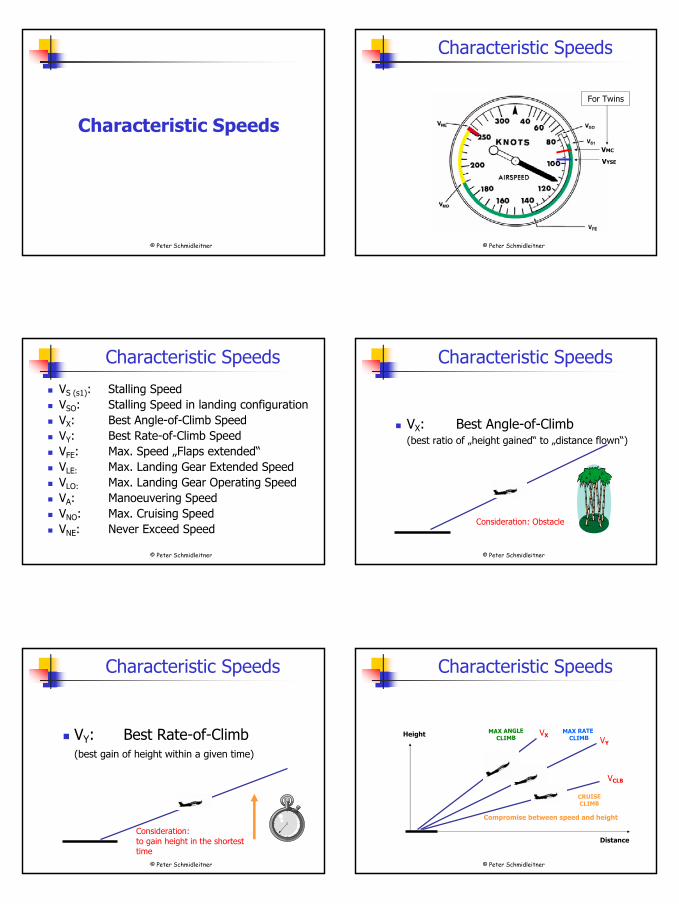
VY: Best Rate-of-Climb(best gain of height within a given time)
Consideration: to gain height in the shortesttime
Characteristic Speeds
© Peter Schmidleitner
Height
Distance
VXVY
VCLB
MAX ANGLE CLIMB
MAX RATECLIMB
CRUISECLIMB
Compromise between speed and height
Characteristic Speeds

2
© Peter Schmidleitner
VA: Manoeuvering speedMaximum „flaps up“ speed in a steep turn.(Below VA and with flaps retracted the aircraft structure cannot beoverstressed.)
Usually also defined as:Full or abrupt control surface movement not permissible abovethis speed.Maximum speed in heavy turbulence.
Characteristic Speeds
© Peter Schmidleitner
VA: Manoeuvering speed
Maneuvering speed means the wing is supposedto stall
before it produces enough Gs to break
any part of the airplane.
Characteristic Speeds
© Peter Schmidleitner
Manoeuvering EnvelopeLoad Factor
Speed
0 g
1 g
Stall area
Stall area
Vs
VA VNO VNE
© Peter Schmidleitner
Manoeuvering Speed VA
?VA not indicated on the ASI !
© Peter Schmidleitner
VNO: Max. Structural Cruising SpeedMaximum speed in cruiseAbove VNO the permissible gust load is reduced; thereforeVNO should be exceeded in smooth air only.
Characteristic Speeds
© Peter Schmidleitner
VNE: Never Exceed SpeedMust not be exceeded in any operation!
Characteristic Speeds
3
© Peter Schmidleitner
Density Altitude
© Peter Schmidleitner
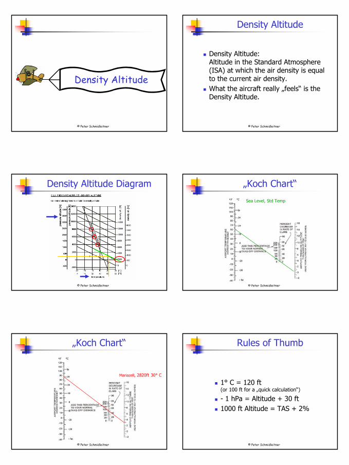
Density Altitude
Density Altitude:Altitude in the Standard Atmosphere(ISA) at which the air density is equalto the current air density.What the aircraft really „feels“ is theDensity Altitude.
© Peter Schmidleitner
Density Altitude Diagram
© Peter Schmidleitner
„Koch Chart“
Sea Level, Std Temp
© Peter Schmidleitner
„Koch Chart“
Mariazell, 2820ft 30° C
© Peter Schmidleitner
Rules of Thumb
1° C = 120 ft(or 100 ft for a „quick calculation“)
- 1 hPa = Altitude + 30 ft1000 ft Altitude = TAS + 2%

4
© Peter Schmidleitner
Take-off and LandingPerformance
© Peter Schmidleitner
Take-off Performance
What do we want?
© Peter Schmidleitner
Take-off Performance
To stop on the runway if take-off has to be abandoned
© Peter Schmidleitner
Take-off Performance
To clear the runway end at the specified„screen height“ when the take-off iscontinued
© Peter Schmidleitner
Take-off Performance
To achieve the minimum climb gradientprescribed by regulations
© Peter Schmidleitner
Take-off Performance
To clear the obstacles in the climb path
5
© Peter Schmidleitner
Take-off Performance
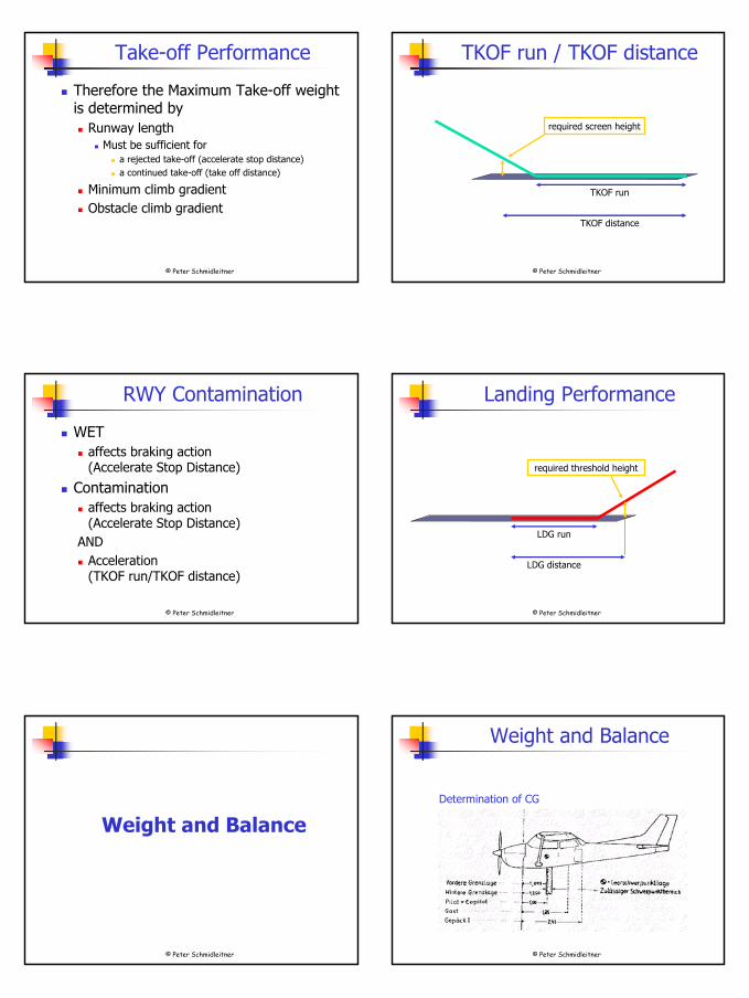
Therefore the Maximum Take-off weightis determined by
Runway lengthMust be sufficient for
a rejected take-off (accelerate stop distance)a continued take-off (take off distance)
Minimum climb gradientObstacle climb gradient
© Peter Schmidleitner
TKOF run / TKOF distance
required screen height
TKOF run
TKOF distance
© Peter Schmidleitner
RWY Contamination
WET affects braking action(Accelerate Stop Distance)
Contaminationaffects braking action(Accelerate Stop Distance)
ANDAcceleration(TKOF run/TKOF distance)
© Peter Schmidleitner
Landing Performance
required threshold height
LDG run
LDG distance
© Peter Schmidleitner
Weight and Balance
© Peter Schmidleitner
Determination of CG
Weight and Balance
6
© Peter Schmidleitner
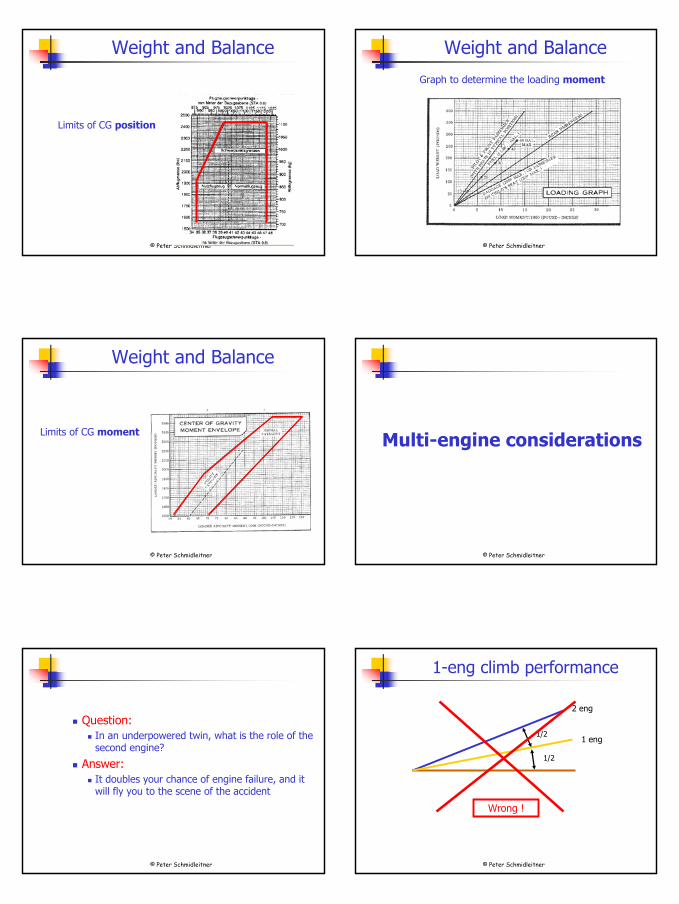
Limits of CG position
Weight and Balance
© Peter Schmidleitner
Weight and Balance
Graph to determine the loading moment
© Peter Schmidleitner
Limits of CG moment
Weight and Balance
© Peter Schmidleitner
Multi-engine considerations
© Peter Schmidleitner
Question:In an underpowered twin, what is the role of thesecond engine?
Answer:It doubles your chance of engine failure, and itwill fly you to the scene of the accident
© Peter Schmidleitner
1-eng climb performance
2 eng
1 eng1/2
1/2
Wrong !

7
© Peter Schmidleitner
2 eng
1 eng
1/2
1/2
0 eng = glide
1-eng climb performance
© Peter Schmidleitner
2 eng
1 eng
1/2
1/2
0 eng = glide
1-eng climb performance
© Peter Schmidleitner
How serious is an engine failure ?It depends !
„Scale of seriousness“
1 10Hard to notice, hardly worth to notice
1 or 2
Extremely serious, immediate action required
10Unrecoverable
11Here you must be proficient
© Peter Schmidleitner
Engine fail – sequence of events
Asymmetric thrustYaw (heading changes)Slip After a while direction would changeUse rudder to counter the slip„step on the ball“Apply bank to avoid turning„raise the dead“
© Peter Schmidleitner
„Critical Engine“
The engine you most regret losing is called thecritical engine. In a twin where both engines rotate clockwise, that will be the left engine. Certification rules:
The „critical engine“ is producing a higher VMC speed. The „critical-inoperative-engine“ for performanceconsiderations is that engine which, wheninoperative, results in the lowest rate of climb.
© Peter Schmidleitner
Factors causing an engine to be the„critical engine“:
Helical propwashTwisted liftP-factor
„Critical Engine“
8
© Peter Schmidleitner
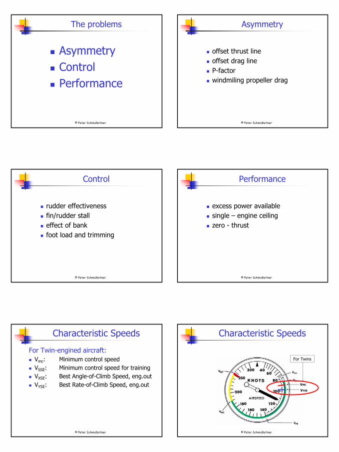
The problems
AsymmetryControlPerformance
© Peter Schmidleitner
Asymmetry
offset thrust lineoffset drag lineP-factorwindmiling propeller drag
© Peter Schmidleitner
Control
rudder effectivenessfin/rudder stalleffect of bankfoot load and trimming
© Peter Schmidleitner
Performance
excess power availablesingle – engine ceilingzero - thrust
© Peter Schmidleitner
For Twin-engined aircraft:Vmc: Minimum control speedVSSE: Minimum control speed for trainingVXSE: Best Angle-of-Climb Speed, eng.outVYSE: Best Rate-of-Climb Speed, eng.out
Characteristic Speeds
© Peter Schmidleitner
Characteristic Speeds
VMC
VYSE
For Twins
9
© Peter Schmidleitner
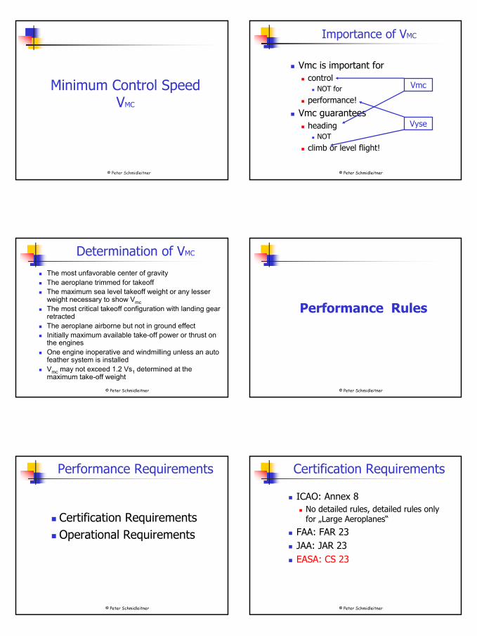
Minimum Control SpeedVMC
© Peter Schmidleitner
Importance of VMC
Vmc is important forcontrol
NOT for
performance!
Vmc guaranteesheading
NOT
climb or level flight!
Vmc
Vyse
© Peter Schmidleitner
Determination of VMC
The most unfavorable center of gravityThe aeroplane trimmed for takeoffThe maximum sea level takeoff weight or any lesserweight necessary to show VmcThe most critical takeoff configuration with landing gearretractedThe aeroplane airborne but not in ground effectInitially maximum available take-off power or thrust on the enginesOne engine inoperative and windmilling unless an autofeather system is installedVmc may not exceed 1.2 Vs1 determined at themaximum take-off weight
© Peter Schmidleitner
Performance Rules
© Peter Schmidleitner
Performance Requirements
Certification RequirementsOperational Requirements
© Peter Schmidleitner
Certification Requirements
ICAO: Annex 8No detailed rules, detailed rules onlyfor „Large Aeroplanes“
FAA: FAR 23JAA: JAR 23EASA: CS 23

10
© Peter Schmidleitner
All the following is for„Light Twins“,
i.e. 2722 kg or lesswith a VS0 of 61 kts or below
© Peter Schmidleitner
CS 23 Requirements
General (CS 23.45)
Performance to be determined in followingconditions:
ISA, still airSea level up to 10.000 ftOAT STD up to STD + 30
© Peter Schmidleitner
CS 23 Requirements
SpeedsVR: min 1,05 VMC of 1,1 VS1, w.i.h.V at 50ft: highest of: 1,1 VMC
1,2 VS1
safe V withcritical engine failed
VREF: VMC *) or 1,3 VSO, w.i.h.*) flaps in highest TKOF setting
© Peter Schmidleitner
Take-off performance CS 23.53 (b)
Take-off distance (TOD): to be determined (all engines at TKOF PWR, TKOF Flaps, Gear down)
Accelerate stop distance (ASD): no requirement
1-eng out TKOF climb:no requirement
CS 23 Requirements
© Peter Schmidleitner
A practical hint
Since ASD is not published, you might consider
to add the take-off roll and the landing roll
or even better, to add the take-off distance and thelanding distance
Required RWY length
Required RWY length
© Peter Schmidleitner
CS 23 Requirements
Climb performance all engines CS 23.65 (a)
At Sea Level 8,4% withMax continuous power on both enginesGear upFlaps TKOFSpeed min 1,1 VMC or 1,2 VS1, w.i.h.

11
© Peter Schmidleitner
CS 23 Requirements
Climb performance 1-eng out CS 23.67 (a)
At 5000ft withCritical engine featheredMax continuous powerGear upFlaps upSpeed min 1,2 VS1
No specific gradient required, steady climbor descent gradient to be determined
© Peter Schmidleitner
En-route climb / descent performanceCS 23.69
At each weight, altitude and temperatureall engines and 1-eng outmax continuous powergear up, flaps upMin speed:
all engines: 1,3 VS11-eng out: 1,2 VS1
No specific gradient required, steady climbor descent gradient to be determined
CS 23 Requirements
© Peter Schmidleitner
Landing performance CS 23.73
Landing distance to be determinedfor ISA temperature at each weight and altitudewith 3° (5,2%) APCH angle to 50ft, constantconfiguration(higher APCH angle if demontrated to be safe)safe transition to balked LDG at 50ft with max. LDG weight must be possible
CS 23 Requirements
© Peter Schmidleitner
Balked Landing CS 23.77 (a)
Minimum climb gradient 3,3% at Sea LevelTKOF power both enginesGear downFlaps LDG or retracted within 2 seconds withoutaltitude lossVREF
CS 23 Requirements
© Peter Schmidleitner
Operational Requirements
ICAO: Annex 6For General Aviation: Part II
No detailed rules, only: operation must be in compliance with
airworthiness certificateState-of-registry limitationsnoise certification
JAA: JAR-OPSFor (Corporate) General Aviation: JAR-OPS 2
not yet published
© Peter Schmidleitner
JAR-OPS 1
For Commercial Aviation: JAR-OPS 1,Aeroplanes which are
Propeller drivenMAPSC max 9Weight < 5700 kg
are: Performance Class BBut: might have to be considered as single engine aeroplane!
12
© Peter Schmidleitner
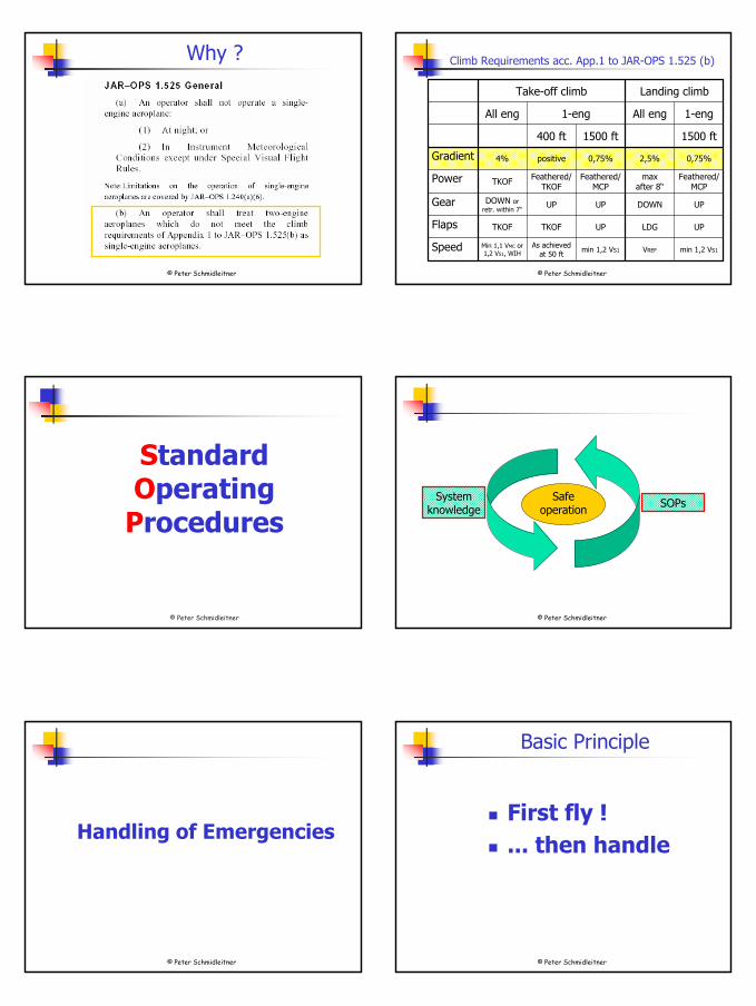
Why ?
© Peter Schmidleitner
Climb Requirements acc. App.1 to JAR-OPS 1.525 (b)
min 1,2 VS1VREFmin 1,2 VS1As achieved
at 50 ftMin 1,1 VMC or1,2 VS1, WIH
Speed
UPLDGUPTKOFTKOFFlaps
UPDOWNUPUPDOWN orretr. within 7“
Gear
Feathered/MCP
maxafter 8“
Feathered/MCP
Feathered/TKOFTKOFPower
0,75%2,5%0,75%positive4%Gradient
1500 ft1500 ft400 ft
1-engAll eng1-eng All eng
Landing climbTake-off climb
© Peter Schmidleitner
Standard Operating
Procedures
© Peter Schmidleitner
System knowledge SOPsSafe
operation
© Peter Schmidleitner
Handling of Emergencies
© Peter Schmidleitner
Basic Principle
First fly !... then handle

13
© Peter Schmidleitner
„PPAA“
Power
Performance
Analysis
Action
Max power
Gear? Flaps? Minimum speed?Identify engineverify engineFeather, shut down
© Peter Schmidleitner
The 3-5-4 Rule
3: airspeed, ball, needle
5: mixture, prop, throttle, gear, flaps
4: identify, verify, feather, secure
© Peter Schmidleitner
The 3-5-4 Rule
3: airspeed, ball, needle
5: mixture, prop, throttle, gear, flaps
4: identify, verify, feather, secure
FLY !
Handle !
© Peter Schmidleitner
The 3-5-4 Rule
3: airspeed, ball, needle
5: mixture, prop, throttle, gear, flaps
4: identify, verify, feather, secure
Power Performance
Analysis Action
Thank you for yourattention!


![Examination AE1201 Aerospace Design and System … · loading value [climb gradient curve would shift up, hence intersecting the TO-curve 1 at a lower wing loading value] ... Even](https://img.dokumen.tips/doc/110x75/5b5240887f8b9ac4368d4b3e/examination-ae1201-aerospace-design-and-system-loading-value-climb-gradient.jpg)