Embed Size (px)
Citation preview

Fundamental J. Thermal Science and Engineering, Vol. 2, Issue 1, 2012, Pages 37-52 Published online at http://www.frdint.com/
:esphras and Keywords shell and tube, heat exchanger, LMTD method, effectiveness-NTU
method.
*Corresponding author
Received January 11, 2012
© 2012 Fundamental Research and Development International
PERFORMANCE ANALYSIS OF SHELL AND TUBE HEAT
EXCHANGERS USING AN EDUCATIONAL APPLICATION
JOAQUÍN ZUECOa, SEYEDALI VEDADb, MOHAMMADALI GHORBANIb,
NILOOFAR HEIDARIb, MEHRNOOSH ZEINALKHANIb and
ALIREZA HEIDARIb,*
aETS Ingeniería Industrial
Departamento de Ingeniería Térmica y Fluidos
Campus Muralla del Mar
Universidad Politécnica de Cartagena
30202 Cartagena (Murcia), Spain
bInstitute for Advanced Studies
Tehran 14456-63543, Iran
e-mail: [email protected]
Abstract
The shell and tube heat exchangers are devices used very much in the
industrial processes in many applications. These elements can have
characteristics very special, in its use as well as in its design, therefore
each system being a particular problem. The program developed uses
simultaneously the LMTD and the effectiveness-NTU methods to such
important heat transfer devices and may prove pedagogically useful to
undergraduate mechanical engineering students attending heat transfer
courses. The examples in this paper illustrate the power of the software
developed in thermal sciences calculations with application to the heat-
exchanger in configuration on line, staggered arrangement and of tube
double. It is hoped that the software will bridge the gap between the
JOAQUÍN ZUECO et al.
38
teaching of engineering fundamentals and the existing industry practice of
shell and tube heat exchanger design.
1. Introduction
The demand for educational software is growing exponentially with the surge of
interest in educational reform, the internet, and distance learning. Educational
applications must be very flexible because curricula and teaching styles vary
tremendously among institutions, locations, and even among instructors at the same
institution. In the classroom, educators and students have an investment in traditional
monolithic applications that can bias them against adopting new technologies. A lot
has been written about designing heat exchangers, and specifically, shell-and-tube
heat exchangers. For example, the book by Kern [1] published in 1950 details basic
design procedures for a variety of heat exchangers. Since the publication of that
book, with the advent of computers, design procedures have become sophisticated
even though the basic goals of design remain the same. This paper presents a
didactical software developed for the design of shell and tube heat exchangers. Shell-
and-tube heat exchangers (STHEs) are used extensively throughout the process
industry and as such a basic understanding of their design, construction and
performance is important to the practicing engineer. They are commonly used in
process applications and in the air conditioning and refrigeration industry. They are
also widely used as oil coolers, power condensers, preheaters and steam generators in
both fossil fuel and nuclear-based energy production applications. They are also
widely used. Although they are not specially compact, their robustness and shape
make them well suited for high pressure operations.
The design of a heat exchanger involves initial conditions in which the following
variables are known: (i) process-fluid rate of flow (ii) change in temperature of
process fluid (iii) inlet temperature of utility fluid (for cooling or heating). With this
information, the engineer must prepare a design for the optimum exchanger that will
meet the required process conditions. Ordinarily, the following results must be
determined: (i) heat-transfer area (ii) exit temperature and flow rate of utility fluid
(iii) number, length, diameter, and arrangement of tubes (iv) tube-side and shell-side
pressure drops and (v) efficiency.
To make the most of exchanger design software, one needs to understand shell-
and-tube heat exchangers (STHEs) classification, exchanger components, tube
layout, baffling, pressure drop, and mean temperature difference. However, a

PERFORMANCE ANALYSIS OF SHELL AND TUBE HEAT …
39
previous good understanding of the underlying principles of exchanger design is
needed to use the software effectively. The software called INTERCAM, was
developed to be used in undergraduate classes of Mechanical and Chemical
Engineering. The use of the software facilitates the development of individual or
group projects, in which the situation can develop its creativity through the scanning
of a real problem.
The software is suitable for teaching thermal design of shell and tube heat
exchangers to senior undergraduate students in mechanical and chemical engineering
and also to train new graduate engineers in thermal design. Students may be asked to
use the software to undertake a few mini projects in shell and tube heat exchanger
design. The software allows changing operation and design conditions such as
temperature and flow inlet and outlet in shells and tubes, number and length of tubes,
inside and outside diameter of tubes, number of passes, shell outside diameter, heat
transfer coefficients in shells and tubes, heat transfer coefficient global, velocities of
the flows and fouling factor. The three examples studied in this work illustrate how
the software can be used in such a manner.
The present work shows the software structure developed for teaching of the
shell and tubes heat exchangers. INTERCAM is very easy to use and user friendly. It
is a software tool that is made to demonstrate the thermal design calculations of shell
and tube heat exchangers. The program shows the static behavior of these devices
under different design parameters and operations conditions. The software allows
changing operation and design conditions such as temperature and flow inlet in shells
and tubes, number and length of tubes, inside and outside fouling factor.
2. Development of the Software: INTERCAM
The tutorial model has been developed to apply in the teaching of shell and tube
heat-exchanger, programmed in .++C This software has main objective to solve
problems to the heat-exchanger in configuration on line, staggered arrangement and
of tube double. The software is divided in two sections. The first section is employed
to introduce the data of the problem or charger previously a problem. The second
section corresponds to the application to solve the problems.
The use of this software permits to the actors of the learning teaching process
(students and teachers): to realize analysis and synthesis of the process that including
in operations with heat-exchanger, to apply the concepts and theory knowledge of

JOAQUÍN ZUECO et al.
40
various subjects in the practical of laboratory, to learn of manner autonomy and to
incorporate new information and to decide the form more adequate use of it. The
students can do practical in the laboratory with a real system and/or simulations in the
software with data found in the literature. This methodology can be applied in
second/third of a bachelor course. The software for education is a tool useful to get:
class more active, problems with solutions different, programming of tasks of
analysis and others formative actions. The use of this type of tools has been
developed and proposed by various authors [2-6] developed a software structure for
teaching and learning of the dynamics and control of shell and tubes heat exchangers.
This software allows changing operation and design conditions such as temperature
and flow inlet in shells and tubes, number and length of tubes, inside and outside
diameter of tubes, number of passes, shell outside diameter and fouling factor. [7]
introduced the effect of temperature on fouling into the design of heat exchangers,
being quite complex because the final, design-fouling resistance depends on the
history of operation of the exchanger. In the recent past, some experts studied on the
design, performance analysis and simulation studies on heat exchangers [8-11].
It is possible to find two possibilities: development of educational software and
use of commercial software. An overall skeleton of the menu, which is designed to be
very user-friendly, is shown in Figure 1. There are three command boxes, namely
Initial data, Configuration and Results. Initial data presents the values of the problem
load. Configuration is possible to change the data, besides of design a new problem
or to load other problem previously designed (Figure 2). Finally, the values
calculated for all the parameters are shown in results. Figure 3 shows (see [12]) an
example of a type of heat exchanger, a fixed-tube sheet heat exchanger. This device
has straight tubes that are secured at both ends to tube sheets welded to the shell. The
principal advantage of the fixed tube sheet construction is its low cost because of its
simple construction. In fact, the fixed tube sheet is the least expensive construction
type, as long as no expansion joint is required. Other advantages are that the tubes
can be cleaned mechanically after removal of the channel cover or bonnet, and that
leakage of the shell side fluid is minimized since there are no flanged joints. A
disadvantage of this design is that since the bundle is fixed to the shell and cannot be
removed, the outsides of the tubes cannot be cleaned mechanically.

PERFORMANCE ANALYSIS OF SHELL AND TUBE HEAT …
41
Figure 1. Main screen of the INTERCAM program.
Figure 2. Screen of configuration of parameters.
Figure 3. Example of shell-and-tube heat exchanger [8].

JOAQUÍN ZUECO et al.
42
3. Educational Objectives
A heat exchanger is a device in which energy is transferred from one fluid to
another across a solid surface. Exchanger analysis and design therefore involve both
convection and conduction. Two important problems in heat exchanger analysis are
(i) rating existing heat exchangers and (ii) sizing heat exchangers for a particular
application. The shell and tube heat exchanger is equipment largely used at chemical
industries. The developed software is intended to be used by undergraduate
mechanical and chemical engineering students at the second year level. It can
therefore be easily appreciated that the developed software has versatile teaching and
educational uses.
The software can be a useful tool:
(i) To introduce the student to the basic concepts of heat-exchanges.
(ii) To enable the student to interactively create and utilize different types of
dispositions of this type of heat-exchanger.
(iii) To make the student appreciate the effects of various pertinent-actors such
as global and convective heat transfer coefficients, efficiency, shell and tube passes,
shell diameter, etc.
(iv) To qualify the student to interpret the results obtained.
(v) To enable the student to learn the fundamentals of this type of device.
4. Mathematical Model
The LMTD method can be readily used when the inlet and outlet temperatures of
both the hot and cold fluids are known. When the outlet temperatures are not known,
the LMTD can only be used in an iterative scheme. In this case the effectiveness-
NTU method can be used to simplify the analysis. The basic heat exchanger
equations applicable to shell and tube exchanger are shown here:
Total heat load transfer
,FTmAUq cco ⋅∆⋅⋅=� (1)
where U is the global heat transfer referred to the area ,oA coefficient that depends
that the heat transfer coefficients (inside and outside), geometry of the exchanger and
thermal properties of both fluids. A is the heat transfer area, ccTm∆ is the

PERFORMANCE ANALYSIS OF SHELL AND TUBE HEAT …
43
logarithmic mean temperature difference for the pure countercurrent flow
configuration and F is the configuration correction factor for multiple tube-side
and/or shell-side passes.
( ),
12
ln1
o
ioo
ii
o
hkL
ddA
hA
AU
+π
+
= (2)
,2 LrA oo π= (3)
( ) ( )
( )
( )
,ln
ciho
cohi
cihocohicc
TT
TT
TTTTTm
−
−
−−−=∆ (4)
where hiT and ciT are the hot and cold inlet temperatures, respectively, hoT and coT
are the corresponding outlet temperatures.
The value of F depends upon the exact arrangement of the streams within the
exchangers, the number of exchangers in series, and two dimensionless parameters
defined in terms of the terminal temperatures of the two streams:
( )
( ),
cico
hohi
TT
TTR
−
−= (5)
( )
( ).
ciho
cico
TT
TTP
−
−= (6)
The mathematical relationships between R, P and F can be found in numerous
books [1, 13], we have considered in this software the configurations more used, 1-2
and 2-4. Values of F below 0.75 at the lowest should not be used, because it means
that substantial additional area must be supplied in the heat exchanger to overcome
the inefficient thermal profile. F is unity for the cases of purely parallel and
countercurrent flow. The Arithmetic Mean Temperature Difference is the following
in this case.
( ) ( )
( )
( )
.ln
coho
cihi
cohocihip
TT
TT
TTTTTm
−
−
−−−=∆ (7)
The expression of Tm∆ for the case purely concurrent (parallel) is rarely used.
The LMTD method and NTU method are used in the software developed. The NTU
method is an alternative to calculate the total heat transfer rate. This method brings

JOAQUÍN ZUECO et al.
44
out the individual effects of not only the total thermal conductance UA but also that
the capacity rates hC and ,cC so appears a new dimensionless number,
denominated number of heat transfer units:
,minCUANTU = (8)
where minC is the smaller of the two capacity rates.
Other dimensionless number is the heat exchanger effectiveness ,ε which is
defined as the ratio between the actual heat transfer rate q� and the maximum heat
transfer that could take place in the heat exchanger ( ).maxminmax TCq ∆=�
.maxqq ��=ε (9)
Heat-transfer coefficient
The tube side heat-transfer coefficient is a function of the physical properties
(viscosity, thermal conductivity and specific heat), the tube diameter and very
importantly, mass velocity. It is necessarily calculated the Reynolds number and the
Prandtl number. The variation in liquid viscosity is quite considerable; so, this
physical property has the most dramatic effect on heat-transfer coefficient. The
fundamental equation for turbulent heat-transfer inside tubes is:
.027.0 33.08.0 PrReNu = (10)
The models derived above are simulated using the software developed in this work
and called INTERCAM. To built this program, it was necessary to use the
programming Language .++C
4. Results and Discussions
Usually, the flow rates and the physical properties of the two streams involved
are specified, and the temperatures at which the fluids are available are known. If the
outgoing temperature of one of the streams is not specified, usually a constraint (e.g.,
the temperature of the cooling water cannot exceed )C99° is given. Then, by an
energy balance, the outgoing temperature of the second stream can be calculated
along with the heat duty. The heat duty q� is usually fixed by the required service.
The tube diameter, tube length, shell types, etc. are all standardized and are available
only in certain sizes and geometry. The selected heat exchanger has to meet or
PERFORMANCE ANALYSIS OF SHELL AND TUBE HEAT …
45
exceed this requirement.
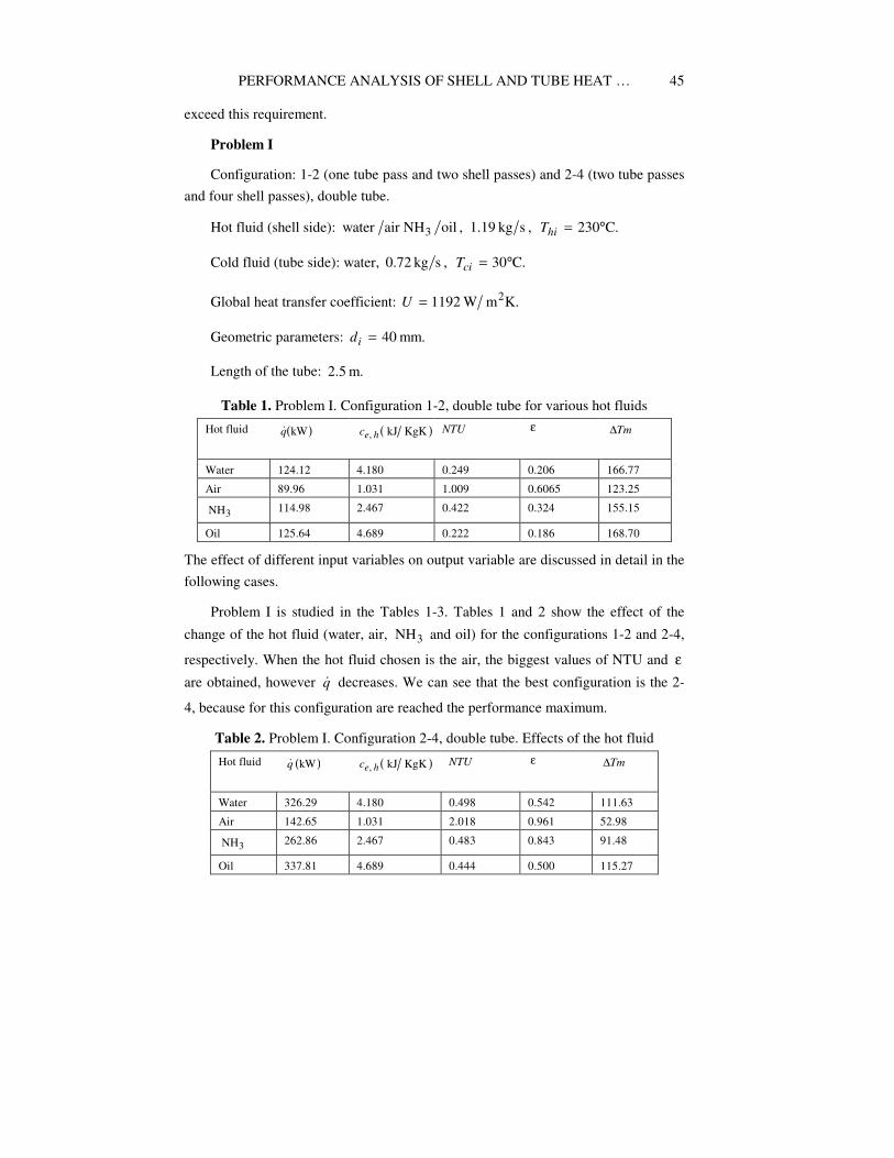
Problem I
Configuration: 1-2 (one tube pass and two shell passes) and 2-4 (two tube passes
and four shell passes), double tube.
Hot fluid (shell side): ,oilNHairwater 3 ,skg1.19 C.230°=hiT
Cold fluid (tube side): water, ,skg72.0 C.30°=ciT
Global heat transfer coefficient: K.mW1192 2=U
Geometric parameters: mm.40=id
Length of the tube: m.2.5
Table 1. Problem I. Configuration 1-2, double tube for various hot fluids
Hot fluid ( )kWq� ( )KgKkJ, hec
NTU ε Tm∆
Water 124.12 4.180 0.249 0.206 166.77
Air 89.96 1.031 1.009 0.6065 123.25
3NH 114.98 2.467 0.422 0.324 155.15
Oil 125.64 4.689 0.222 0.186 168.70
The effect of different input variables on output variable are discussed in detail in the
following cases.
Problem I is studied in the Tables 1-3. Tables 1 and 2 show the effect of the
change of the hot fluid (water, air, 3NH and oil) for the configurations 1-2 and 2-4,
respectively. When the hot fluid chosen is the air, the biggest values of NTU and ε
are obtained, however q� decreases. We can see that the best configuration is the 2-
4, because for this configuration are reached the performance maximum.
Table 2. Problem I. Configuration 2-4, double tube. Effects of the hot fluid
Hot fluid ( )kWq� ( )KgKkJ, hec
NTU ε Tm∆
Water 326.29 4.180 0.498 0.542 111.63
Air 142.65 1.031 2.018 0.961 52.98
3NH 262.86 2.467 0.483 0.843 91.48
Oil 337.81 4.689 0.444 0.500 115.27

JOAQUÍN ZUECO et al.
46
Table 3 shows the effects of inlet hot fluid temperature. It can be seen that an
increase in the hiT leads to a decrease in heat exchanger effectiveness and NTU.
Besides, the actual heat transfer rate increases as the inside hot fluid temperature
increases.
Table 3. Problem I. Configuration 1-2, double tube. Effects of inlet hot fluid
temperature
( )C°hiT ε NTU ( )kWq� Tm∆
220 0.607 1.011 85.39 117.01
200 0.608 1.015 76.29 104.54
180 0.609 1.018 67.23 92.14
160 0.610 1.021 58.20 79.76
Problem II
Configuration: in-line tube banks (Figure 4a).
Hot fluid (shell side): water, s,kg55.3 C,120°=hiT .sm5.0=hu
Cold fluid (tube side): oil, ,skg5 ,sm4.0=cu C,30°=ciT C.85°=coT
Global heat transfer coefficient: K.mW1550 2=U
Geometric parameters: mm.25mm,20 == oi dd
With this parameters are obtained the following constant values for all the cases
studied: 46,=N 0.611,=ε 1.630,=NTU kgK,kJ2=pfc pcc kgK,kJ18.4=
kW.550=q� Problem II is studied in the Tables 4 and 5. In Table 4 is used the 1-2
configuration, while in Table 5 is used the 2-4 configuration. In this case the effect of
the global heat transfer coefficient is analyzed. An increase of this parameter leads to
a decrease in the heat transfer and of the length of the tubes, which was expected.
However, ε and NTU does not change. As in the previous case, the best
configuration is the 2-4, because for this configuration are obtained less values of the
heat transfer area and of the length of the tubes with the same performance.
Table 4. Problem II. Configuration 1-2, in-line tube banks. Effects of the global heat
transfer coefficient
( )KmW 2U ( )2mA ( )mL ε NTU
1250 13.039 1.8045 0.611 1.630
1350 12.073 1.6708 0.611 1.630
1450 11.240 1.5556 0.611 1.630
1550 10.515 1.4552 0.611 1.630

PERFORMANCE ANALYSIS OF SHELL AND TUBE HEAT …
47
Table 5. Problem II. Configuration 2-4, in-line tube banks. Effects of the global heat
transfer coefficient
( )KmW 2U ( )2mA ( )mL ε NTU
1250 10.651 0.7370 0.767 1.331
1350 9.862 0.6824 0.767 1.331
1450 9.182 0.6354 0.767 1.331
1550 8.589 0.5944 0.767 1.331
Problem III
Configurations: 1-2, in-line and staggered tube banks (Figure 4).
Hot fluid (shell side): water, C.70C,100,skg3.3 °=°= hohi TT
Cold fluid (tube side): water, C.35,sm3.0,skg1.5 °=ciT
Thermal conductivity of the tube: .mKW100=k
Geometric parameters: mm.25mm,20 == oi dd
Baffle spacing: m.2.0=bS
m.05.0m,075.0 21 == XX
(a)
(b)
Figure 4. Configurations: (a) Configuration in-line tube banks, (b) Configuration
staggered tube banks.

JOAQUÍN ZUECO et al.
48
Table 6. Problem III. Configuration in-line tube banks. Effects of the distance
between deflectors
( )mbS ( )mKWch
( )mL ( )2mA ( )msΦ ( )KmW 2U
0.10 1886.9 1.319 11.396 0.3725 968.4
0.15 1461.5 1.516 13.098 0.4169 842.5
0.20 1219.3 1.689 14.598 0.4570 755.9
0.25 1059.4 1.848 15.964 0.4938 691.2
0.30 949.4 1.994 17.232 0.5281 640.4
The effect of the baffle spacing is analyzed in Table 6. It can be appreciated that
when bS increases, LA, and the shell diameter ( )sΦ increases, while ch (heat
transfer coefficient for cold fluid or tube side) and U (global heat transfer coefficient)
decreases. In Table 7 is studied the effect of the number and distribution
( )rowcolumn × of the tubes. It can be seen that an increase of N deals a decrease of
the velocity, of the length tube and of the global heat transfer coefficient. The shell
diameter ( )sΦ increases when N increases, however, sΦ is 0.4773 and 0.4718 for
( )rows5columns1260 ×=N and ( ),rows6columns1166 ×=N respectively.
Table 7. Problem III. Configuration staggered tube banks. Effects of the number and
distribution of the tubes
N ( )smfu ( )mL ( )2mA ( )msΦ ( )KmW 2U
( )51050 × 0.328 1.6337 12.831 0.4357 860.0
( )61060 × 0.273 1.4475 13.643 0.4498 808.9
( )51260 × 0.273 1.5415 14.529 0.4773 759.6
( )61166 × 0.248 1.4051 14.568 0.4718 757.5
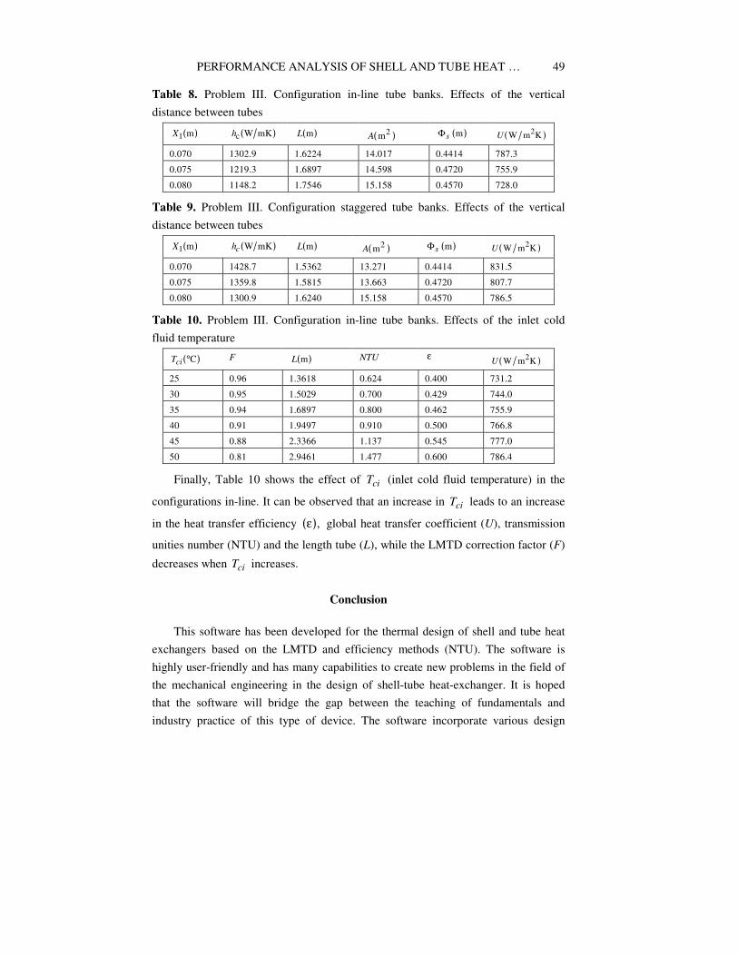
Tables 8 and 9 show the effect of 1X (vertical distance between tubes) for the
configurations in-line and staggered tube banks, respectively. It can be seen that an
increase of 1X leads to a decrease in global heat transfer coefficient (U) and heat
transfer coefficient .ch Besides, L and A increase when 1X increases. We can see
that for the staggered tube banks configuration are obtained bigger values of U and
ch than the in-line tube banks configuration. Besides, the values of L and A are
smaller, therefore the staggered tube banks configuration is the most adequate.
PERFORMANCE ANALYSIS OF SHELL AND TUBE HEAT …
49
Table 8. Problem III. Configuration in-line tube banks. Effects of the vertical
distance between tubes
( )m1X ( )mKWch ( )mL ( )2mA ( )msΦ ( )KmW 2U
0.070 1302.9 1.6224 14.017 0.4414 787.3
0.075 1219.3 1.6897 14.598 0.4720 755.9
0.080 1148.2 1.7546 15.158 0.4570 728.0
Table 9. Problem III. Configuration staggered tube banks. Effects of the vertical
distance between tubes
( )m1X ( )mKWch ( )mL ( )2mA ( )msΦ ( )KmW 2U
0.070 1428.7 1.5362 13.271 0.4414 831.5
0.075 1359.8 1.5815 13.663 0.4720 807.7
0.080 1300.9 1.6240 15.158 0.4570 786.5
Table 10. Problem III. Configuration in-line tube banks. Effects of the inlet cold
fluid temperature
( )C°ciT F ( )mL NTU ε ( )KmW 2
U
25 0.96 1.3618 0.624 0.400 731.2
30 0.95 1.5029 0.700 0.429 744.0
35 0.94 1.6897 0.800 0.462 755.9
40 0.91 1.9497 0.910 0.500 766.8
45 0.88 2.3366 1.137 0.545 777.0
50 0.81 2.9461 1.477 0.600 786.4
Finally, Table 10 shows the effect of ciT (inlet cold fluid temperature) in the
configurations in-line. It can be observed that an increase in ciT leads to an increase
in the heat transfer efficiency ( ),ε global heat transfer coefficient (U), transmission
unities number (NTU) and the length tube (L), while the LMTD correction factor (F)
decreases when ciT increases.
Conclusion
This software has been developed for the thermal design of shell and tube heat
exchangers based on the LMTD and efficiency methods (NTU). The software is
highly user-friendly and has many capabilities to create new problems in the field of
the mechanical engineering in the design of shell-tube heat-exchanger. It is hoped
that the software will bridge the gap between the teaching of fundamentals and
industry practice of this type of device. The software incorporate various design

JOAQUÍN ZUECO et al.
50
options for the heat exchangers including the variations in the tube diameter, tube
pitch, shell diameter, number of tube passes, baffle spacing, baffle cut, etc. Three
configurations can be used, on line, staggered arrangement and of tube double. The
software was tested using some thermal problems and found to provide results that
are very accurate. Trial tests show that INTERCAM solves the problems directly and
effectively using an ordinary PC.
Nomenclature
A [ ]2m Heat-transfer area
ec [ ]kgKkJ Specific heat
id [ ]m Tube inside diameter
od [ ]m Tube outside diameter
F [ ]− LMTD correction factor
h [ ]KmW 2 Heat-transfer coefficient
k [ ]mKW Thermal conductivity
L [ ]m Length tube
q� [ ]KW Heat transfer rate
m� [ ]skg Flow rate
N [ ]− Number of tubes
NTU [ ]− Transmission unities number
Nu [ ]− Nusselt number
Pr [ ]− Prandtl number
P [ ]− Dimensionless parameter, LMTD
R [ ]− Dimensionless parameter, LMTD
fR [ ]kJKm2 Fouling resistance

PERFORMANCE ANALYSIS OF SHELL AND TUBE HEAT …
51
Re [ ]− Reynolds number
T [ ]C° Temperature
u [ ]sm Velocity
U [ ]KmW 2 Global heat transfer coefficient
bS [ ]m Baffle spacing
Special characters
ε [ ]− Efficiency
µ [ ]smkg Viscosity
sΦ [ ]m Shell diameter
Subscripts
c Cold
h Hot
i Inlet
o Outlet
s Shell
t Tube
References
[1] D. Q. Kern, Process Heat Transfer, McGraw-Hill, New York, 1950.
[2] H. I. Abu-Mulaweh, Experimental comparison of heat transfer enhancement methods
in heat exchangers, Int. J. Mech. Engrg. Edu. 31 (2003), 160-167.
[3] C. K. Leong, K. C. Toh and Y. C. Leong, Shell and tube heat exchanger design
software for educacional applications, Int. J. Engrg. Edu. 14 (1998), 217-224.
[4] L. M. F. Lona, F. A. N. Fernandes, M. C. Roque and S. Rodrigues, Developing an
educational software for heat exchangers and heat exchanger networks projects,
Computers & Chemical Engineering 24(2-7) (2000), 1247-1251.

JOAQUÍN ZUECO et al.
52
[5] F. L. Tan and S. C. Fok, An educational computer-aided tool for heat exchanger
design, Computer Applications in Engineering Education 14 (2006), 77-89.
[6] F. Machuca and O. Urresta, Educational software for the teaching of the dynamics and
control of shell and tube heat exchangers, Rev. Fac. Ing. Univ. Antioquia 44 (2008),
52-60.
[7] D. Butterworth, Design of shell-and-tube heat exchangers when the fouling depends
on local temperature and velocity, Appl. Thermal Engineering 22 (2002), 789-801.
[8] M. T. Aghareed, M. A. El-Rifai, Y. A. El-Tawil and R. M. Abdel-Monen, A new
dynamic model for shell and tube heat exchangers, Energy Conservation Management
32 (1991), 439-446.
[9] S. Anantharaman, Design and construction of shell and tube heat exchangers, Chem.
Ind. Dev. Incorporat. Chemical Processing Engineering 11 (1997), 15-21.
[10] S. A. Mandavgane, M. A. Siddique, A. Dubey and S. I. Pandharipande, Modeling of
heat exchangers using artificial neural network, Chemical Engineering World, 2004,
pp. 75-80.
[11] A. K. Yusuf and O. Guraras, A computer program for designing of shell and tube heat
exchangers, Appl. Thermal Engineering 24 (2004), 1797-1805.
[12] R. Mukherjee, Effectively design shell-and-tube heat exchangers, Chemical
Engineering Progress, 1998.
[13] A. Bejan, Heat Transfer, John Wiley & Sons, Inc., New York, 1993.