Embed Size (px)
Citation preview

Performance analysis of an axial exhaust diffuser downstream of an un-shrouded turbine
R. Blanco1 & S. Farokhi2
1MAN Diesel & Turbo Schweiz AG, Zürich, Switzerland 2Aerospace Engineering Department, The University of Kansas, USA
Abstract
Performance of an axial exhaust diffuser downstream of an un-shrouded turbine rotor is computationally analyzed. Three-dimensional analysis of two turbine stage-exhaust diffuser configurations has been performed. In one case, the turbine rotor is shrouded and in the second case, the rotor is un-shrouded. The static pressure recovery coefficient in the exhaust diffuser is used as the diffuser performance parameter. It has been found that the over the tip leakage flow in the un-shrouded rotor emerges as a swirling wall jet at the upper wall of the diffuser. The case of the shrouded rotor produced no wall jet at the entrance to the diffuser and the turbine exit flow was “quasi-uniform”. The presence of the wall jet allowed the annular diffuser outer wall angle at stall point to increase from 12° (in the shrouded rotor case) to 18° in the un-shrouded turbine. By changing the angular speed of the rotor, the effect of the swirl in the turbine exit plane on the performance of the diffuser was explored. In the shrouded rotor case, the diffuser recovers higher static pressure when the inlet is swirl-free. In this case, the performance of the diffuser is independent of whether the turbine exit flow has co- or counter-swirl. However, in the presence of un-shrouded rotors, higher static pressure recovery was achieved when the core flow possessed slight counter-swirl. This observation was more pronounced when larger diffuser upper wall angles were considered. Keywords: Wall jet flow, over the tip leakage, residual swirl flow, exhaust diffuser, turbine stage, static pressure recovery.
1 Introduction
In the power generation industry, the shaft power created by gas turbines is utilized to drive generators to produce electricity. To optimize the shaft power, it
www.witpress.com, ISSN 1743-3533 (on-line) WIT Transactions on Engineering Sciences, Vol 82, © 2014 WIT Press
doi:10.2495/AFM140361
Advances in Fluid Mechanics X 419

is crucial that the turbine extracts as much energy as possible from the fluid. To this end, an axial exhaust diffuser is employed that discharges to atmosphere and thus creates sub-atmospheric pressure at the turbine exit. Therefore, optimizing the design of the diffuser so that it can recover as much static pressure as possible will enhance the power production capability of the gas turbine and the thermal efficiency of the cycle. Towards this goal, Japikse [1] presents extensive research on diffuser flow technology from various investigators in the field that may be used in the power plant design. In the clearance region of free-tip turbine rotors, the fluid is not deflected by the blade and thus does not contribute to the work output of the stage; hence it is considered a source of loss and carries an efficiency penalty [2–6]. Subsequent losses as the over the tip leakage flow rolls up into a vortex and mixes out with the core flow of the turbine passage can also be of considerable importance [7–10]. Alternatively, observations made by Bammert et al. [11] as well as other investigators in the field, show that the presence of the rotor over the tip leakage flow emerges as a co-swirling wall jet with an excess of axial momentum into the diffuser. This excess of momentum at the rotor tip, which is essentially a wall jet, energizes the boundary layer and thus postponing diffuser stall. Moreover tests confirm that some counter-swirl in the core flow increases the performance of the diffuser. Based on these observations, a theoretical approach of the effect of the rotor tip clearance flow of un-shrouded turbine rotors on the performance of diffusers was performed by Farokhi [12]. Taking Bammert et al. [11] assumptions, that is, the tip clearance flow and core flow expand to the same exit pressure ( 2 2cW W ), the absolute swirl in the tip clearance exit is equal to the
absolute swirl at the flow inlet, and that the axial velocity within the passage remains constant, Farokhi [12] represented the flow at the exit of a rotor through a series of velocity triangles. He distinctly discerned whether the rotor core flow was in co-swirl, counter-swirl or swirl free. He then identified that the presence of a small core counter-swirl flow generates a shear layer of axial vorticity. This vortex sheet enhances mixing of the outer diffuser flow and boundary layer, acting in effect as a “vortex generator”. Figure 1 (Farokhi [12]) shows the case of counter-swirl in the core flow and the mechanism of streamwise vortex generation downstream of an un-shrouded turbine rotor. The performance improvement of an annular exhaust diffuser coupled to an un-shrouded turbine stage is presented in this paper. A computational fluid dynamics study is performed with an annular diffuser attached to a shrouded turbine stage first and then coupled to an un-shrouded turbine stage of the same characteristics. The performance of the diffuser is assessed and compared for both cases in terms of the static pressure recovery at several diffuser outer wall angles.
2 Numerical analysis
The numerical simulations were conducted utilizing the commercial CFD software ANSYS CFX v13.0 [13]. A multi-block grid domain composed of three
www.witpress.com, ISSN 1743-3533 (on-line) WIT Transactions on Engineering Sciences, Vol 82, © 2014 WIT Press
420 Advances in Fluid Mechanics X

Figure 1: Rotor tip clearance flow in an exhaust diffuser [12].
blocks was employed, namely a stator, a rotor and a diffuser. For the turbine stage the grid was realized with ANSYS TurboGrid v13.0 and the diffuser with ANSYS ICEM CFD v13.0 through a circumferential extrusion of a 2D grid. Except for the exhaust diffuser domain that changes its geometry with different diverging outer wall angles, and the rotor domain that has two geometries, one shrouded and one un-shrouded, the stator domain geometry remains unchanged for all cases studied. The solver chosen in this investigation computes the full 3D compressible Navier-Stokes and heat equations with the turbulence model k-ω based Shear-Stress-Transport (SST) with automatic near wall treatment, which is based on Menter’s model [14]. In order to resolve the boundary layers accurately, averaged y+ < 10.0 values at the walls were used, which are well within a good accuracy range of the k-ω SST turbulence model. Plus the requirement of having at least 15 grid nodes within the boundary layer is also met [13]. The total blade counts of stators and rotors in the turbine stage are 36 and 54 respectively, as shown in Table 1, making it an exact match when 2 stators and 3 rotors are used, that produces a periodic pitch of 20°. However since no transient stator/rotor effects are considered, only one stator, one rotor and one diffuser passages are considered in this investigation. Thus, the interfaces between the stationary and rotating domains are treated through a mixing plane algorithm that averages the fluxes spatially (in a circumference direction) [13]. Rotational periodicity is then applied at the sides of the turbine stage and diffuser to close the boundary requirements. The boundary conditions set at the inlet are total pressure, total temperature and axial flow direction and at the outlet is static pressure with radial equilibrium, see Table 1. Lastly, the setting of the inlet boundary conditions for the k-ω SST turbulence model is low turbulence intensity. This means that a turbulence intensity of 1% and the viscosity ratio µT/µ of 1.0 is used. The turbulence intensity estimates the initial turbulent kinetic energy, k, and the viscosity ratio is used to calculate the specific dissipation, ω.
www.witpress.com, ISSN 1743-3533 (on-line) WIT Transactions on Engineering Sciences, Vol 82, © 2014 WIT Press
Advances in Fluid Mechanics X 421
Solution convergence was recognized when the root mean square of the residuals reduced to a value below 10-5, the mass imbalance was below 0.01% and no changes in the flow field results were observed.
3 Turbine stage flow simulation
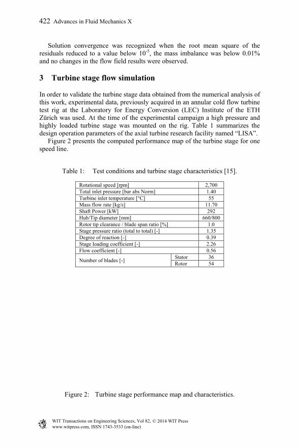
In order to validate the turbine stage data obtained from the numerical analysis of this work, experimental data, previously acquired in an annular cold flow turbine test rig at the Laboratory for Energy Conversion (LEC) Institute of the ETH Zürich was used. At the time of the experimental campaign a high pressure and highly loaded turbine stage was mounted on the rig. Table 1 summarizes the design operation parameters of the axial turbine research facility named “LISA”. Figure 2 presents the computed performance map of the turbine stage for one speed line.
Table 1: Test conditions and turbine stage characteristics [15].
Rotational speed [rpm] 2,700 Total inlet pressure [bar abs Norm] 1.40 Turbine inlet temperature [°C] 55 Mass flow rate [kg/s] 11.70 Shaft Power [kW] 292 Hub/Tip diameter [mm] 660/800 Rotor tip clearance / blade span ratio [%] 1.0 Stage pressure ratio (total to total) [-] 1.35 Degree of reaction [-] 0.39 Stage loading coefficient [-] 2.26 Flow coefficient [-] 0.56
Number of blades [-] Stator 36 Rotor 54
Figure 2: Turbine stage performance map and characteristics.
www.witpress.com, ISSN 1743-3533 (on-line) WIT Transactions on Engineering Sciences, Vol 82, © 2014 WIT Press
422 Advances in Fluid Mechanics X
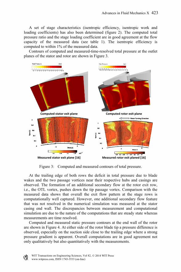
A set of stage characteristics (isentropic efficiency, isentropic work and loading coefficients) has also been determined (figure 2). The computed total pressure ratio and the stage loading coefficient are in good agreement at the flow capacity of the measured data (see table 1). The isentropic efficiency is computed to within 1% of the measured data. Contours of computed and measured-time-resolved total pressure at the outlet planes of the stator and rotor are shown in Figure 3.
Computed stator exit plane Computed rotor exit plane
Measured stator exit plane [16] Measured rotor exit planed [16]
Figure 3: Computed and measured contours of total pressure.
At the trailing edge of both rows the deficit in total pressure due to blade wakes and the two passage vortices near their respective hubs and casings are observed. The formation of an additional secondary flow at the rotor exit row, i.e., the OTL vortex, pushes down the tip passage vortex. Comparison with the measured data shows that overall the exit flow pattern at the stage rows is computationally well captured. However, one additional secondary flow feature that was not resolved in the numerical simulation was measured at the stator casing end wall. The discrepancies between measurement and computational simulation are due to the nature of the computations that are steady state whereas measurements are time resolved. Computed and measured static pressure contours at the end wall of the rotor are shown in Figure 4. At either side of the rotor blade tip a pressure difference is observed, especially on the suction side close to the trailing edge where a strong pressure gradient is apparent. Overall computations are in good agreement not only qualitatively but also quantitatively with the measurements.
www.witpress.com, ISSN 1743-3533 (on-line) WIT Transactions on Engineering Sciences, Vol 82, © 2014 WIT Press
Advances in Fluid Mechanics X 423

Computed pressure contours Measured pressure contours [15]
Figure 4: Turbine rotor static pressure at shroud.
Recirculating fluid trapped in the separation bubble at the rotor blade tip corner on the pressure side was also captured in the numerical simulation as seen in Figure 5 (top view) and observed in the turbine test stand with the visualization of oil deposits on the rotor blade tip (bottom view). This separation bubble marks the location of the vena contracta of the OTL.
Figure 5: Recirculation bubble (computed left, measured right [15]).
4 Axial exhaust diffuser simulation with steady inlet conditions
The turbine stage provides very realistic boundary and operating conditions for which the performance of the diffuser can be assessed numerically in terms of its static pressure recovery characteristic. Due to time and budget restrictions, no experimental measurements of the diffuser performance are available. In this analysis several annular diffusers with different upper wall opening angles are investigated. Moreover two turbine-diffuser stage configurations are utilized: one with a shrouded and one with an un-shrouded rotor. Thus the effect of the over the tip leakage flow on the performance of the diffuser is isolated. Moreover by varying the turbine rotor rotational speed the influence of the inlet flow swirl on the performance of the diffuser is also explored.
Oil deposition due to recirculation in the separation bubble close to the vena contracta
www.witpress.com, ISSN 1743-3533 (on-line) WIT Transactions on Engineering Sciences, Vol 82, © 2014 WIT Press
424 Advances in Fluid Mechanics X

Axial velocity contours at the rotor exit row, for the shrouded and un-shrouded rotor cases, are shown in Figure 6. The exit flow from the shrouded rotor row is quasi-uniform, whereas the flow from the rotor clearance retains high levels of kinetic energy, as expected. Moreover, since the flow in the rotor clearance is not deflected the OTL emerges into the downstream annular diffuser in the form of co-swirling wall jet. Additionally, the OTL rolls up into a vortex and merges with the passage vortex, a region of momentum deficit (i.e., wake) located near the rotor tip suction side is also observed. Furthermore, due to the inter-stage mixing algorithm chosen in this numerical analysis, the flow that enters to the diffuser is circumferentially averaged. Therefore the OTL and passage core flow contributions are pre-mixed at diffuser inlet. Computed contours of axial velocity at the mid-plane of the diffuser coupled to the shrouded rotor stage are shown in Figure 7.
Stage with shrouded rotor Stage with unshrouded rotor
Figure 6: Computed axial velocity contours at the exit of the rotor.
8 degrees 10 degrees
12 degrees 14 degrees
Figure 7: Diffuser axial velocity contours with a shrouded turbine stage.
www.witpress.com, ISSN 1743-3533 (on-line) WIT Transactions on Engineering Sciences, Vol 82, © 2014 WIT Press
Advances in Fluid Mechanics X 425

At the inlet of the diffuser no large velocity gradients exist. A deceleration of the flow takes place within the diffuser and thus static pressure is recovered. The rapid conversion of the fluid kinetic energy into static pressure rise near the upper wall leads to the onset of stall. This behavior is clearly observed as early as a 10° outer wall angle. Indeed, reverse flow regions develop in this section when the diffuser outer wall angle is increased to 12°. The performance of the diffuser in terms of the static pressure recovery coefficient is shown in Figure 10. The computed contours of axial velocity at the mid-plane of the diffuser coupled to the un-shrouded rotor stage for several opening angles are shown in Figure 8. The wall jet created from the turbine rotor OTL flow is clearly observed in the upper wall region of the diffuser. Large velocity gradients exist between the wall jet and the main passage flow and between the wall jet and the diffuser upper wall boundary layer. In this case, there is no sign of momentum deficit flow near the upper wall. Indeed, the wall jet has energized the low momentum fluid of the boundary layer and consequently the diffuser can tolerate larger diffusing angles without stalling. Hence, the diffuser recovers higher static pressure.
12 degrees 14 degrees
16 degrees 18 degrees
Figure 8: Diffuser axial velocity contours with turbine un-shrouded stage.
Furthermore, the wall jet that emanates from the rotor tip clearance and the core passage flow are not swirl free. While the core flow swirl is extracted by the rotor, the tip clearance flow nearly maintains its angular momentum. Therefore, the two distinct flows emerging from the turbine rotor row have two well defined swirl angles. This fact may be seen in Figure 9 where computed contours of swirl in the diffuser at the mid-plane are shown. High gradients of swirl exist between the wall jet and the core passage flows. For this specific turbine operation, the averaged core passage and the averaged over the tip leakage flows are counter-swirling, but at very different angles. This manifestation gives rise to a vortex
www.witpress.com, ISSN 1743-3533 (on-line) WIT Transactions on Engineering Sciences, Vol 82, © 2014 WIT Press
426 Advances in Fluid Mechanics X

sheet with streamwise vorticity that separates the core flow of the rotor passage channel and the over the tip leakage flow. As the mixing process within the diffuser takes place the intensity of the swirl decays.
4 degrees 8 degrees
Figure 9: Diffuser swirl flow contours with turbine un-shrouded stage.
A comparison of the static pressure recovery coefficient for both turbine-diffuser configurations is shown in Figure 10. To evaluate this coefficient between the inlet and outlet planes of the diffuser averaging of the flow quantities are performed according to Cumpsty and Horlock [17]. The static pressure recovery for diffuser opening angles less than 12° is around 10% higher in the diffuser with the un-shrouded rotor configuration. While the diffuser with the shrouded rotor configuration stalls above angles of 12°, the presence of the wall jet in the other diffuser allows for higher opening angles without stalling.
Figure 10: Static pressure recovery coefficient with the opening angle.
Altering the rotational speed of the rotor allows the inlet swirl into the diffuser to vary. Figure 11 shows the diffuser static pressure recovery coefficient as a function of the averaged inlet swirl for several diffuser upper wall angles for both turbine stage configurations. A reduction in the inlet swirl to the diffuser
www.witpress.com, ISSN 1743-3533 (on-line) WIT Transactions on Engineering Sciences, Vol 82, © 2014 WIT Press
Advances in Fluid Mechanics X 427

allows for higher static pressure recovery, as expected. With the shrouded rotor configuration the maximum static pressure gain corresponds to an inlet swirl angle of 0° (swirl-free). Additionally, the static pressure recovery is symmetrical with respect to the inlet swirl angle, as expected. In contrast, the un-shrouded rotor produces a diffuser pressure recovery that exhibits a maximum with a slight inlet core flow counter-swirl. This trend is more pronounced for higher diffuser divergence angles such as 12° and 18°.
Stage with shrouded rotor Stage with unshrouded rotor
Figure 11: Cp at different opening angles in function of rotor flow exit angle.
Table 2 summarizes the static pressure recovery coefficient at various averaged diffuser inlet flow swirls for the case of the diffuser with an outer wall angle of 18°. The swirl contributions of the over the tip leakage and main passage core flows are also distinguished. It is seen that the diffuser performance is optimized when the core flow is at a slight counter-swirl.
Table 2: Static pressure coeff. and swirl for the 18° diffuser/un-shrouded stage.
Rotor exit flow Swirl (α3) [°] -40.4 -20.5 -4.2 0.1 4.4 8.7 12.9 OTL Swirl [°] -13.9 3.2 13.3 15.8 18.2 20.5 22.7
Core flow Swirl [°] -42.3 -24.6 -9.2 -4.9 -0.6 3.9 8.3 Cp [-] 0.36 0.56 0.66 0.67 0.68 0.67 0.66
5 Conclusions
By simulating the flow inside an industrial gas turbine stage and then coupling it to an exhaust diffuser creates a more realistic performance simulation environment for the diffuser. By studying the shrouded and un-shrouded turbine rotors, the effect of tip clearance on the exhaust diffuser performance is isolated. The over the tip clearance flow emerges as a wall jet at the upper wall of the diffuser, energizing the flow boundary layer and hence postponing diffuser stall.
www.witpress.com, ISSN 1743-3533 (on-line) WIT Transactions on Engineering Sciences, Vol 82, © 2014 WIT Press
428 Advances in Fluid Mechanics X

As demonstrated, the maximum diffuser outer wall angle without the presence of the wall jet, before the diffuser stalls, was 12°. With the presence of the wall jet, diffuser opening angles above 18° are possible. Consequently, the wall jet helps the boundary layer flow in the diffuser to remain attached longer and thus recovers higher static pressure. By altering the inlet flow swirl to the diffuser with a shrouded and an un-shrouded rotor, the effect of co- and counter-swirl is studied. In the first case, it was found that the diffuser recovers higher static pressure when the inlet flow is swirl free. As expected, the static pressure recovery coefficient curve showed a perfect symmetry around a swirl of 0°. In contrast, higher pressure was recovered by the diffuser when the core flow was at a slight counter-swirl direction. Indeed this gives rise to a shear layer with streamwise vorticity that forms between the wall jet and the core flow. This vortex sheet enhances mixing near the wall. This effect was more noticeable as the opening angle of the diffuser increased. Hence the swirl of the wall jet and the core flow affects the performance of the diffuser. Even though a numerical simulation using the mixing plane algorithm mimics the behavior of a rotating machine, it has the drawback that it averages the flow field at the inter-stages. Another alternative could be the use of the “frozen rotor” method. This method was utilized by Kluss et al. [18] who justified its use as “a first-order approach to the unsteady flow”. Indeed, the authors believe that the axial exhaust diffuser design process should use the fully unsteady computational simulations in order to capture the physics of unsteady wall jet injection, vortex shedding and mixing in the diffuser.
Acknowledgements
The first author (RB) gratefully acknowledges the contribution of the LEC Institute of ETH Zürich in providing the turbine stage geometry and experimental data. Special thanks go to Prof. R.S. Abhari and Dr. N. Chokani.
References
[1] Japikse, D., Turbomachinery Diffuser Design Technology, Concepts, ETI, Inc., 1984.
[2] Booth, T.C, “Rotor Tip Leakage Part I – Basic Methodology”, J. of Engineering for Power, Vol. 104, pp. 154-161, 1983.
[3] Harvey, N.W., “Turbine Blade Tip Design and Tip Clearance Treatment”, Von Karman Institute for Fluid Dynamics, Lecture Series 2004-02.
[4] Moore, J., Tilton, J.S., “Tip Leakage Flow in a Linear Turbine Cascade”, ASME J. of Turbomachinery, Vol. 100, pp. 18-26, 1988.
[5] Yaras, M.I., Sjolander, S.A., “Effects of Simulated Rotation on Tip Leakage in a Planar Cascade of Turbine Blades. Part I: Tip Gap Flow”, ASME J. of Turbomachinery, Vol. 114, pp. 660-667, 1992.
[6] Graham, J.A.H., “Investigation of a Tip Clearance Cascade in a Water Analogy Rig”, ASME J. of Engineering for Gas Turbines and Power, Vol. 108, pp. 38-46, 1986.
www.witpress.com, ISSN 1743-3533 (on-line) WIT Transactions on Engineering Sciences, Vol 82, © 2014 WIT Press
Advances in Fluid Mechanics X 429

[7] Bindon, J.P., Morphis, G. “The Development of Axial Turbine Leakage Loss for Two Profiled Tip Geometries Using Linear Cascade Data”, ASME Paper 90-GT-152, 1990.
[8] Bindon, J.P., “The Measurement and Formation of Tip Leakage Loss”, ASME J. Turbomachinery, Vol. 111, pp. 257-263, 1987.
[9] Farokhi, S., “Analysis of Rotor Tip Clearance Loss in Axial-Flow Turbines”, AIAA J. of Propulsion and Power, Vol. 4, No. 5, pp. 452-457, September-October 1988.
[10] Denton, J.D., “Loss Mechanisms in Turbomachines”, ASME J. of Turbomachinery, Vol. 115, pp. 621-656, 1993.
[11] Bammert, K., Klaeukens, H., Hartmann, D., “Der Einfluss des radialen Schaufelspalts auf den Wirkungsgrad mehrstufige Turbinen”, VDI-Zeitschrift, Vol. 110, No. 10, April 1968, pp. 390-395.
[12] Farokhi, S., “Coupled Performance of Axial Exhaust Diffusers and Low-Pressure Turbine”, Private Communication, October 2013. Professor of Aerospace Engineering at the University of Kansas, USA.
[13] ANSYS CFX-Solver Modeling Guide, ANSYS, Inc. Release 13.0, 2010. [14] Menter, F.R., “Two-equation eddy-viscosity turbulence models for
engineering applications”, AIAA Journal, 32(8), pp. 1598-1605, 1994. [15] Behr, T., “Control of Rotor Tip Leakage and Secondary Flow by Casing
Air Injection in Un-shrouded Axial Turbines”, PhD Diss. ETH Zurich, 2007.
[16] Behr, T., Kalfas, A.I., Abhari, R.S., “Unsteady Flow Physics and Performance of a One-and-1/2-Stage Un-shrouded High Work Turbine”, ASME J. of Turbomachinery, Vol. 129, pp. 348-359, 2007.
[17] Cumpsty, N.A., Horlock, J.H., “Averaging Non-Uniform Flow for a Purpose”, ASME Turbo Expo, Proceedings of GT2005-68081, 2005.
[18] Kluss, D., Wiedermann, A., Volgmann, W., “Impact of Gas Turbine Outflow on Diffuser Performance – A Numerical Study”, Power for Land, Sea, and Air, Proceedings of ASME Turbo Expo, GT2004-53043, 2004.
www.witpress.com, ISSN 1743-3533 (on-line) WIT Transactions on Engineering Sciences, Vol 82, © 2014 WIT Press
430 Advances in Fluid Mechanics X