Embed Size (px)
Citation preview

Drilling and Production Operations Ref: INDEX
SPECIAL WELLS M ANUAL, VOLUME II:UNDERBALANCED DRILLING
Issue: Feb 2000
INDEX Page 1 of 1
Introduction UBDL 01
Prospect Assessment UBDL 02
Underbalanced Drilling Techniques UBDL 03
Summar y of Underbalanced Drilling Techniques UBDL 04
References and Further Reading UBDL 05

Drilling and Production Operations Ref: UBDL 01
SPECIAL WELLS M ANUAL, VOLUME II:UNDERBALANCED DRILLING
Issue: Feb 2000
SECTION 1 INTRODUCTION Page 1 of 9
TABLE OF CONTENTS
1. INTRODUCTION.................................................................................................... 3
1.1 DEFINITION OF UNDERBALANCED DRILLING ........................................... 3
1.2 ADVANTAGES OF UNDERBALANCED DRILLING........................................ 3
1.2.1 Increased Penetration Rates ...................................................................... 3
1.2.2 Increased Bit Life........................................................................................ 4
1.2.3 Minimised Hole Problems ........................................................................... 4
1.2.3.1 Lost Circulation .......................................................................................... 4
1.2.3.2 Differential Sticking .................................................................................... 4
1.2.3.3 Reactive Shales......................................................................................... 4
1.2.4 Continuous Formation Evaluation............................................................... 4
1.2.5 Earlier Production ....................................................................................... 4
1.2.6 Formation Damage..................................................................................... 5
1.2.7 Increased Productive Index ........................................................................ 5
1.2.8 Risk ............................................................................................................ 5
1.2.9 Reduced Environmental Impact.................................................................. 5
1.2.10 Reduced CAPEX and Improved NPV ......................................................... 6
1.3 DISADVANTAGES OF UNDERBALANCED DRILLING.................................. 6
1.3.1 Increased Drilling Equipment Cost.............................................................. 6
1.3.2 Wellbore Stability........................................................................................ 6
1.3.3 Maintaining Continuous Underbalanced Conditions.................................... 6
1.3.4 Formation Damage..................................................................................... 6
1.3.5 Spontaneous Imbibition .............................................................................. 7
1.3.6 High Permeability Zones............................................................................. 7
1.3.7 Well Control................................................................................................ 7
1.3.8 Drilling Medium Composition ...................................................................... 7

INTRODUCTION Page 2 of 9
1.4 PROSPECT CONSIDERATIONS..................................................................... 7
1.4.1 Naturally Fractured Reservoir ..................................................................... 8
1.4.2 Underpressured Reservoirs........................................................................ 8
1.4.3 Horizontal Wells ......................................................................................... 8
1.4.4 Storage and Disposal Wells ....................................................................... 8
1.4.5 Micro-fractured or Vulgar Formation Invasion............................................. 8
1.4.6 Shallow Wells ............................................................................................. 8
1.4.7 Reservoir Pressure Variations .................................................................... 9

INTRODUCTION Page 3 of 9
1. INTRODUCTIONWhen the hydrostatic head of a drilling fluid is intentionally designed to be lower thanthe pressure of the formation being drilled, the operation is considered asunderbalanced drilling. The hydrostatic head of the drilling fluid may be naturally lessthan the formation pressure or it can be induced. The induced state may be created byadding natural gas, nitrogen or air to the liquid phase of the drilling fluid. Whetherinduced or natural, this may result in an influx of formation fluids which must becirculated from the well and controlled at surface.
1.1 DEFINITION OF UNDERBALANCED DRILLING
When the hydrostatic head of a drilling fluid is intentionally designed to be lower thanthe pressure of the formation being drilled, the operation is considered asunderbalanced drilling. The hydrostatic head of the drilling fluid may be naturally lessthan the formation pressure or it can be induced. The induced state may be created byadding natural gas, nitrogen or air to the liquid phase of the drilling fluid. Whetherinduced or natural, this may result in an influx of formation fluids which must becirculated from the well and controlled at surface.
1.2 ADVANTAGES OF UNDERBALANCED DRILLING
The primary reason for underbalanced drilling is to improve the economic viability of aproject. Not every well is a candidate for underbalanced drilling. In some cases, distinctdisadvantages may exist in trying to execute an underbalanced drilling operation whencompared to a simpler conventional overbalanced application. Each potentialcandidate must therefore be carefully screened to validate an underbalanced drillingproject.
1.2.1 Increased Penetration Rates
Underbalanced drilling can decrease drilling costs in many cases because of anincrease in drilling penetration rate. The increase in penetration rate occurs becausethe underbalanced condition causes the formation to implode into the wellbore andthus accelerates the performance of the bit. Since the rate of penetration is controlledby several parameters, the increase is difficult to quantify. Case studies of penetrationrates whist drilling underbalanced have shown that there is an increase of up to 10times in the rate of penetration than that in a balanced or overbalanced situation.
INTRODUCTION Page 4 of 9
1.2.2 Increased Bit Life
Underbalanced drilling is accomplished by using lighter drilling fluids which by designcarry fewer solids or weighting materials. This has two positive effects. Firstly, theabrasive nature of the drilling fluid is reduced. Secondly, rock confinement is reducedby the underbalanced condition therefore reducing the work required to remove a setvolume of rock. These two factors greatly increase the run life of the bit. A furtherbenefit realised from the extended bit life is potentially the reduced quantity of trips andhence reduced drilling costs.
1.2.3 Minimised Hole Problems
1.2.3.1 Lost Circulation
In the case of underbalanced drilling there is no force driving the drilling fluid into theformation. Hence underbalanced drilling effectively reduces or eliminates lostcirculation problems. However, lost circulation may still occur if the equivalentcirculating density (ECD) pressure in the wellbore exceeds the formation pressure.
1.2.3.2 Differential Sticking
In the case of underbalanced drilling, the filter cake and the positive pressure exertedby the drilling fluid are eliminated. This reduces the hydrostatic force along the bottomhole assembly (BHA) which contributes to removing the forces that cause differentialsticking.
1.2.3.3 Reactive Shales
Certain underbalanced drilling processes can be advantageous when drilling sensitiveor swelling shales. However, drilling certain shales or unconsolidated formationsunderbalanced may create hole stability problems. Pre-planning and review ofgeological and historical drilling information are imperative to a successful UBDprogramme.
1.2.4 Continuous Formation Evaluation
Underbalanced drilling allows continuous testing of the potential productive horizonwhile drilling. In some cases, overbalanced drilling methods can mask reservoirs.
1.2.5 Earlier Production
When underbalanced drilling techniques are used, production equipment can beconfigured to allow production whilst drilling. The production from the well begins whenthe productive zone is drilled. There are cases where the value of the liquidhydrocarbons produced has provided the cash flow for the drilling operation, eg AustinChalk, Texas.

INTRODUCTION Page 5 of 9
1.2.6 Formation Damage
Underbalanced drilling techniques can reduce or eliminate formation impairment byminimising the skin effect. The reduction or elimination of a positive skin in the drillingprocess can eliminate the need for stimulation of the reservoir during the completionphase. Reservoir impairment occurs not only during the drilling phase therefore theproject should be designed so that the underbalanced programme is maintainedthrough both the drilling phase and the completion phase.
1.2.7 Increased Productive Index
Underbalanced drilling reduces formation damage which yields higher initial producingrates, and therefore associated increased productive index (PI) values, than equivalentwells drilled overbalanced. Higher initial production rates in conjunction with higher PIvalues result in greater early recovery meaning faster pay-out, greater rate of returnand possibly a higher total return on investment.
1.2.8 Risk
Uncontrolled losses into a fracture system in an underpressured zone can evacuatethe annulus quickly, which could induce well kicks from another zone and create anuncontrollable situation in the form of a kick and/or an underground blowout.By contrast, an increased risk exists due to the lack of overpressure resulting inreduced barriers from a well control point of view. This has to be carefully managedusing specialist technology and equipment.
1.2.9 Reduced Environmental Impact
Environmental and cleanup aspects of underbalanced drilling operations need to beconsidered in the design of the system. Utilising air, mist, nitrogen or foam reduces theliquid requirement thereby reducing the environmental cleanup requirements andpotential liability. Chemicals used for foam generation are fairly benign but should stillbe evaluated in order to comply with any applicable environmental restriction.
Formation fluids produced during underbalanced drilling operations can, however,cause environmental concerns. In addition to brines and hydrocarbons, the possibilityof having to deal with hydrogen sulphide and other dangerous gases is also an issue.A review of local environmental regulations as well as existing geological and reservoirdata are important in the planning and design phase of any underbalancedprogramme.

INTRODUCTION Page 6 of 9
1.2.10 Reduced CAPEX and Improved NPV
A good candidate well in conjunction with a properly planned and executed programmewill result in a higher rate of penetration (ROP), increased bit life, reduced number oftrips, a reduction in drilling fluid costs and fewer drilling problems. These savings aretranslated directly to the economic viability of the project. Higher initial production ratesin conjunction with higher PI values result in greater early recovery which means fasterpay-out and greater rate of return on investment.
1.3 DISADVANTAGES OF UNDERBALANCED DRILLING
Not every prospect is a candidate for underbalanced drilling. There are factors that canbe an advantage or disadvantage, depending on the aspects of the project. A potentialcandidate should be screened carefully and the advantages weighed against thedisadvantages to properly assess the viability of the operation.
1.3.1 Increased Drilling Equipment Cost
Although an increase in the rate of penetration can be achieved, an underbalanceddrilling operation will require specialised equipment not found on a conventional drillingproject. The additional costs may be offset somewhat by the reduced drilling fluid andrig time costs in some proportion, depending on the project.
1.3.2 Wellbore Stability
In some cases, incompetent shale and/or unconsolidated sands are encountered whendrilling and hydrostatic pressure is sometimes required to support these sections.Underbalanced drilling techniques could be detrimental to both the drilling operationand the completion operation by causing a wellbore stability problem.
1.3.3 Maintaining Continuous Underbalanced Conditions
It may not always be possible to maintain underbalanced conditions. For example,underbalanced conditions may be lost during drilling operations as a result of makingdrillstring connections. The underbalanced condition may also be lost when a well killoperation has to be conducted prior to a trip. In addition, periodic well kill operationsmay have to conducted in order to complete a conventional mud pulsed loggingprogramme or a geosteering function. The underbalanced condition could also bepotentially lost due to localised depletion effects.
1.3.4 Formation Damage
Since there is no filter cake buildup in an underbalanced drilling operation, if theformation is exposed to periodic pulses of overbalanced pressure, rapid and severeinvasion of filtrates and associated solids may occur. If this happens, damage to thereservoir may be more severe than when drilled in an overbalanced condition.

INTRODUCTION Page 7 of 9
1.3.5 Spontaneous Imbibition
Due to adverse capillary pressure relations, it is possible to imbibe water-based fluidsinto the formation in the near wellbore area where it may cause a reduction inpermeability.
1.3.6 High Permeability Zones
Although advantageous to select an underbalanced candidate with high permeability orextensive fracture systems, it may prove to be disadvantageous because of theproblems related to the handling of large gas volumes or reservoir fluids at surface.Should the reservoir have high deliverability and/or high pressure, well control canbecome a major problem.
1.3.7 Well Control
Drilling and completing wells in a flowing condition adds an element of concernregarding safety. Recent developments in rotating blowout preventers (RBOP) andsurface control equipment and the increased use of coiled tubing have increased thereliability and confidence with many underbalanced operations. Well control concernsshould weigh heavily in the candidate well selection.
1.3.8 Drilling Medium Composition
Explosive envelope testing is recommended for each particular reservoir fluid systemor gas composition under consideration.
A major drawback with certain types of underbalanced drilling fluids is the inability touse mud pulsed measurement while drilling (MWD) or geosteering tools whilstunderbalanced. Electronic telemetry tools and wet connectors are available but thereare still depth and temperature limitations to electromagnetic MWD systems andreliability concerns with wet connect systems.
1.4 PROSPECT CONSIDERATIONS
In any underbalanced drilling project the expected gains, the increased productionrates, the increased reserves, the decreased rig time and the associated drillingproblems must outweigh the expected increase in certain drilling costs. There are twomain criteria for deciding whether to implement underbalanced drilling technology in agiven situation:
� Does underbalanced drilling offer significant technical or economic advantagescompared with traditional overbalanced methods?
� Is there an expected increase in value that justifies any associated risk?

INTRODUCTION Page 8 of 9
1.4.1 Naturally Fractured Reservoir
Fracture systems can be plugged with drilling solids or weighting materials in anoverbalanced situation. Underbalanced drilling eliminates the plugging problems andassociated lost circulation.
1.4.2 Underpressured Reservoirs
One application for underbalanced drilling is to drill through underpressured reservoirs.Without underbalanced drilling many prospects could not be drilled due to lostcirculation and associated hole problems. The situation becomes more problematicwhen drilling through a depleted zone into a higher pressure zone. In this case,underbalanced drilling may be the only practical way to drill the prospect.
1.4.3 Horizontal Wells
Many of the candidates to date have been in horizontal fractured carbonates. Multiplefracture networks can be intersected through horizontal drilling and underbalancedtechniques can keep formation impairment to a minimum. Underbalanced drilling canalso eliminate filtrate invasion.
1.4.4 Storage and Disposal Wells
These wells rely on high input/withdrawal rates to be effective. Underbalanced drillingcan help minimise formation impairment under these stressful sandface completioncircumstances where fluids are entering/leaving the reservoir periodically.
1.4.5 Micro-fractured or Vulgar Formation Invasion
In formations that exhibit macroporosity, gravity driven invasion of circulating fluids andsolids can occur on the lower side of the well bore. In the case of low underbalancedpressure or large porosity features, irreparable damage may occur.
1.4.6 Shallow Wells
In shallow wells there may be no improvement in drilling speed or formation damageand no subsequent cost advantage to underbalanced drilling.

INTRODUCTION Page 9 of 9
1.4.7 Reservoir Pressure Variations
As pressure in a producing reservoir depletes, workover operations create damagepotential by using workover fluids. In this situation the fluid recovery after the workovercan be slow. Damage to the reservoir is a possibility and reserves could be lost.Underbalanced techniques for workover operations can help accelerate fluid recoveryand prevent loss of reserves. Wells with alternating high and low pressure productivezones may have a high potential for underground blowouts if drilled underbalanced.These wells require overbalanced drilling to protect reserves and improve safety.

Drilling and Production Operations Ref: UBDL 02
SPECIAL WELLS M ANUAL, VOLUME II:UNDERBALANCED DRILLING
Issue: Feb 2000
SECTION 2 PROSPECT ASSESSMENT Page 1 of 6
TABLE OF CONTENTS
2. PROSPECT ASSESSMENT .................................................................................. 2
2.1 SCREENING PROCESS.................................................................................. 2
2.1.1 Drilling Options ........................................................................................... 2
2.1.2 Data Gathering ........................................................................................... 2
2.1.3 Data Review and Evaluation....................................................................... 2
2.1.4 Economic Analysis ..................................................................................... 3
2.1.5 Technical Analysis...................................................................................... 3
2.2 ACQUISITION OF DATA ................................................................................. 4
2.2.1 Data for Upper Hole Sections ..................................................................... 4
2.2.1.1 Hole Section Properties ............................................................................. 4
2.2.1.2 Formation Properties ................................................................................. 4
2.2.1.3 Influx Fluid and Drilling Fluid Compatibility................................................. 4
2.2.1.4 Formation and Drilling Fluid Compatibility .................................................. 5
2.2.2 Additional Data for Reservoir Interval ......................................................... 5
2.2.2.1 Reservoir Description................................................................................. 5
2.2.2.2 Formation Properties ................................................................................. 5
2.2.2.3 Reservoir Fluid Properties.......................................................................... 5
2.2.2.4 Reservoir Fluid and Drilling Fluid Compatibility .......................................... 6
2.2.2.5 Reservoir Formation and Drilling Fluid Compatibility .................................. 6
2.3 SUITABILITY OF PROSPECT......................................................................... 6
2.4 ECONOMIC ANALYSIS OF UNDERBALANCED DRILLING .......................... 6

PROSPECT ASSESSMENT Page 2 of 6
2. PROSPECT ASSESSMENTAssessment of a prospect is the process used to determine if a well is suitable forunderbalanced drilling. This section will facilitate an understanding or the requirementsof each of the underbalanced drilling techniques described in Section 3. The first stepin underbalanced drilling is the gathering of all existing data. This is followed by areview of the data to determine if the well is a viable candidate for underbalanceddrilling operations. If so, a decision should be made as to which method is appropriatefor that specific well case.
2.1 SCREENING PROCESS
Screening wells can be a time consuming process and should be approached from anegative view point. Every attempt should be made to discover a reason not to drillthe well underbalanced. Eliminating poor candidates should be the drivers to avoidinvesting valuable time, effort and money into the wrong prospect.
2.1.1 Drilling Options
There are three underbalanced drilling options for a well and any of these may be thebest choice:
� Upper hole sections only
� Production hole section only
� Entire well
The screening process consists of the following steps described in Sections 2.1.2,2.1.3, 2.1.4 and 2.1.5.
2.1.2 Data Gathering
Gather existing geological, drilling and reservoir data. This should include allinformation regarding lithology, reservoir and fluids as well as historical drilling recordsand production data. As much current data should be acquired as possible, includingdetails such as present bottom hole pressure (BHP), reservoir and drilling fluidcompatibility studies and formation and drilling fluid compatibility studies.
2.1.3 Data Review and E valuation
A quick look technique should be applied to eliminate unsuitable candidates before toomuch time, effort and finance is invested in the underbalanced drilling design andengineering. The following questions should be used to facilitate the eliminationprocess:
� Will the well produce more if it is drilled underbalanced?

PROSPECT ASSESSMENT Page 3 of 6
� Will it drill faster if it is drilled underbalanced?
� Are there overriding concerns about safety and environmental issues that mighteliminate economics as a deciding factor?
If the answers to the above questions are no, then the well can be designed foroverbalanced drilling operations. If any of the answers are yes, then a quick pressureanalysis should be performed to decide whether a gas-based or fluid-based drillingmedium is appropriate.
2.1.4 Economic Analysis
After determining that the candidate fits the criteria from a macroscopic reservoir andmechanical standpoint, the economic viability of the operation should be reviewed toascertain that there is an economic advantage to drilling underbalanced. This shouldinclude a review of overall operational costs, production/recovery economics, safetyaspects and the environmental restrictions. This process should be followed by acomparison of the economic viability of drilling the well underbalanced as opposed to amore conventional drilling plan.
2.1.5 Technical Analysis
If the economics indicate that underbalanced drilling is feasible, a project team shouldreview the data to determine if the candidate meets all of the technical criteria to drillthe well underbalanced. This study should consist of an in-depth review to ensure thatit is technically feasible and to make a final decision on which method(s) will be used. Ifthis process does not eliminate the well as a candidate, the engineering and planningcan commence.
It is important to consider all aspects, both positive and negative when planning theproject. A multi-discipline group of professionals should be formed, consisting of thefollowing:
Drilling Engineers Underbalanced Drilling Professionals
Geophysicists Geologists
Reservoir Engineers Production Engineers
Other professionals and other service providers involved should be also be consideredand consulted throughout the design phase of the project eg Drilling Contractor,Platform Manager (OIM) etc.

PROSPECT ASSESSMENT Page 4 of 6
2.2 ACQUISITION OF DATA
Compiling as much data as possible is important to the candidate screening process.The following is a combination of data required for drilling each hole section. This hasbeen divided into two sections to separate the upper hole section from the productiveinterval, facilitating analysis by hole section. In cases where the objective is increasedrate of penetration (ROP) to the productive zone and standard drilling through theproduction zone, the productive interval information will not be required. Data listed forthe production hole section are additional to the first data set. All data listed is notrequired to design an underbalanced drilling programme. However, more data ratherthan less will allow better advance engineering and commencement of the programmefurther along the learning curve.
2.2.1 Data for Upper Hole Sections
2.2.1.1 Hole Section Properties
� Pore pressure plot for the interval
� Pressure variations (overpressured or depleted zones)
� Presence of lost circulation zones
� Location of water zones or aquifers
� Productivity of water zones or aquifers
2.2.1.2 Formation Properties
� Formation strengths (fracture gradient data and a plot of the minimum allowablehydrostatic pressure)
� Water-sensitive shale sections
� Sections with high erosion potential
2.2.1.3 Influx Fluid and Drilling Fluid Compatibility
� Emulsion potential
� Corrosion potential
� Contamination of circulating fluid by influx

PROSPECT ASSESSMENT Page 5 of 6
2.2.1.4 Formation and Drilling Fluid Compatibility
� Potential reaction with clays and shales
� Formation dissolution
� Reactivity and transport of cuttings
2.2.2 Additional Data for Reservoir Interval
2.2.2.1 Reservoir Description
� Current target reservoir pressure
� Presence and pressure of multiple zones
� Pressure variation within reservoirs
� Location of oil, gas and water contacts
� Presence of sealing and non-sealing faults
2.2.2.2 Formation Properties
� Reservoir lithology
� Vertical and horizontal permeability
� Porosity
� Pore size and pore throat size distribution
� Presence of faults and fractures
� Formation strengths and initial saturation
� Capillary pressure characteristics
� Wetability and glazing potential
2.2.2.3 Reservoir Fluid Properties
� Compositions
� Asphaltene and paraffin content
� Cloud and pour points
� Viscosity and densities, both downhole and surface values
� Bubble point and properties of rich gases
� Presence of hydrogen sulphide or other hazardous components

PROSPECT ASSESSMENT Page 6 of 6
2.2.2.4 Reservoir Fluid and Drilling Fluid Compatibility
� Emulsion, hydrate and scale potential
� Precipitation or asphalt deposition potential
� Gas entrainment characteristics
� Explosion potential
� Corrosion potential
� Degradation of base fluids by formation fluids
2.2.2.5 Reservoir Formation and Drilling Fluid Compatibility
� Potential reaction with clays
� Potential reaction with hydratable shales
� Formation dissolution
� Drilling fluid selection
� Reactivity and transport of cuttings
2.3 SUITABILITY OF PROSPECT
� Increased rate of penetration
� Increased production
� Overriding safety issues
� Environmental issues
2.4 ECONOMIC ANALYSIS OF UNDERBALANCED DRILLING
� Enhanced production rates and recovery factor
� Time comparison
� Economic NPV analysis
� Risked cost analysis

Drilling and Production Operations Ref: UBDL 03
SPECIAL WELLS M ANUAL, VOLUME II:UNDERBALANCED DRILLING
Issue: Feb 2000
SECTION 3 UNDERBALANCED DRILLINGTECHNIQUES
Page 1 of 67
TABLE OF CONTENTS
3. UNDERBALANCED DRILLING TECHNIQUES........................................................ 7
3.1 DRY AIR DRILLING......................................................................................... 7
3.1.1 Equipment Requirements ........................................................................... 8
3.1.1.1 Surface Equipment..................................................................................... 8
3.1.1.2 Effect of Elevation on Equipment Performance ........................................ 10
3.1.1.3 Bottom Hole Equipment ........................................................................... 10
3.1.1.4 Instrumentation ........................................................................................ 10
3.1.2 Operational Procedures............................................................................ 10
3.1.2.1 Standpipe Pressure.................................................................................. 11
3.1.2.2 Connections ............................................................................................. 11
3.1.2.3 Tripping .................................................................................................... 11
3.1.2.4 Post Cementing Operations ..................................................................... 12
3.1.2.5 Water Influx.............................................................................................. 13
3.1.2.6 Drillstring Washouts ................................................................................. 13
3.1.3 Limitations ................................................................................................ 13
3.1.3.1 Water Influxes .......................................................................................... 14
3.1.3.2 Downhole Fires ........................................................................................ 14
3.1.3.3 Wellbore Stability ..................................................................................... 15
3.1.3.4 MWD/FEWD Systems.............................................................................. 16
3.1.3.5 Air Motors................................................................................................. 16
3.1.3.6 Hydrogen Sulphide................................................................................... 16
3.1.3.7 Torque and Drag ...................................................................................... 16
3.1.4 Reverse Circulation Air Drilling ................................................................. 17
3.1.5 Summary .................................................................................................. 17
3.1.5.1 Advantages .............................................................................................. 17
3.1.5.2 Disadvantages.......................................................................................... 18
3.1.5.3 Design Criteria.......................................................................................... 18

UNDERBALANCED DRILLINGTECHNIQUES
Page 2 of 67
3.2 NITROGEN DRILLING................................................................................... 18
3.2.1 Equipment Selection................................................................................. 19
3.2.1.1 Cryogenic Nitrogen Supply ....................................................................... 19
3.2.1.2 Onsite Nitrogen Generation...................................................................... 20
3.2.1.3 Other Equipment ...................................................................................... 21
3.2.2 Operational Procedures............................................................................ 21
3.2.3 Limitations ................................................................................................ 21
3.2.4 Summary .................................................................................................. 22
3.2.4.1 Advantages .............................................................................................. 22
3.2.4.2 Disadvantages.......................................................................................... 22
3.2.4.3 Design Criteria.......................................................................................... 22
3.3 NATURAL GAS DRILLING............................................................................ 23
3.3.1 Equipment Requirements ......................................................................... 23
3.3.1.1 Surface Equipment................................................................................... 23
3.3.1.2 Gas Detectors .......................................................................................... 24
3.3.1.3 Flaring Arrangements ............................................................................... 24
3.3.2 Operating Procedures............................................................................... 25
3.3.2.1 Hole Cleaning........................................................................................... 25
3.3.2.2 Connections ............................................................................................. 25
3.3.2.3 Tripping .................................................................................................... 25
3.3.2.4 Water Influx.............................................................................................. 26
3.3.3 Limitations ................................................................................................ 26
3.3.4 Summary .................................................................................................. 26
3.3.4.1 Advantages .............................................................................................. 26
3.3.4.2 Disadvantages.......................................................................................... 27
3.3.4.3 Design Criteria.......................................................................................... 27
3.4 MIST DRILLING............................................................................................. 27
3.4.1 Mist Drilling versus Foam Drilling ............................................................. 27
3.4.2 Equipment Requirements ........................................................................ 28
3.4.2.1 Surface Equipment................................................................................... 28
3.4.2.2 Water Supply and Disposal Logistics ....................................................... 29
3.4.2.3 Contingency Defoaming Arrangements .................................................... 30

UNDERBALANCED DRILLINGTECHNIQUES
Page 3 of 67
3.4.3 Operating Procedures............................................................................... 30
3.4.3.1 Hole Cleaning........................................................................................... 30
3.4.3.2 Tripping .................................................................................................... 31
3.4.3.3 Corrosion Inhibitors .................................................................................. 31
3.4.3.4 Liquid and Solid Additives ........................................................................ 31
3.4.4 Limitations ................................................................................................ 31
3.4.4.1 Air Compression....................................................................................... 32
3.4.4.2 Waste Water Disposal.............................................................................. 32
3.4.4.3 Wellbore Instability ................................................................................... 32
3.4.4.4 Corrosion.................................................................................................. 33
3.4.4.5 MWD/FEWD ............................................................................................ 33
3.4.5 Summary .................................................................................................. 33
3.4.5.1 Advantages .............................................................................................. 34
3.4.5.2 Disadvantages.......................................................................................... 34
3.4.5.3 Design Criteria.......................................................................................... 34
3.5 STABLE FOAM DRILLING............................................................................... 35
3.5.1 Foam Drilling versus Dry Air Drilling ......................................................... 35
3.5.1.1 Physical Properties of Foam..................................................................... 36
3.5.1.2 Foaming Agents ....................................................................................... 37
3.5.2 Equipment and Material Requirements..................................................... 37
3.5.2.1 Surface Equipment................................................................................... 37
3.5.2.2 Injected Fluid............................................................................................ 40
3.5.2.3 Environmental Considerations.................................................................. 40
3.5.2.4 Defoaming Arrangements......................................................................... 41
3.5.3 Operating Procedures............................................................................... 41
3.5.3.1 Hole Cleaning........................................................................................... 41
3.5.3.2 Connections ............................................................................................. 41
3.5.3.3 Tripping .................................................................................................... 42
3.5.4 Limitations ................................................................................................ 42
3.5.4.1 Wellbore Instability ................................................................................... 42
3.5.4.2 Waste Water Disposal.............................................................................. 43
3.5.4.3 Downhole Fires ........................................................................................ 43
3.5.4.4 Corrosion.................................................................................................. 43

UNDERBALANCED DRILLINGTECHNIQUES
Page 4 of 67
3.5.5 Summary .................................................................................................. 43
3.5.5.1 Advantages .............................................................................................. 43
3.5.5.2 Disadvantages ......................................................................................... 44
3.5.5.3 Design Criteria ......................................................................................... 44
3.6 STIFF FOAM DRILLING................................................................................... 44
3.6.1 Stiff Foam Drilling versus Stable Foam Drilling......................................... 44
3.6.2 Equipment and Material Requirements..................................................... 45
3.6.2.1 Surface Equipment................................................................................... 45
3.6.2.2 Injected Fluid............................................................................................ 45
3.6.3 Operating Procedures............................................................................... 45
3.6.3.1 Injected Fluid Mixing Considerations ........................................................ 45
3.6.3.2 Recognition of Influxes ............................................................................. 46
3.6.4 Limitations ................................................................................................ 46
3.6.4.1 Gas Influxes ............................................................................................. 46
3.6.4.2 Corrosion.................................................................................................. 46
3.6.4.3 Waste Water Disposal.............................................................................. 46
3.6.4.4 Formation Damage................................................................................... 47
3.6.5 Summary .................................................................................................. 47
3.6.5.1 Advantages .............................................................................................. 47
3.6.5.2 Disadvantages.......................................................................................... 47
3.6.5.3 Design Criteria.......................................................................................... 47
3.7 GASIFIED LIQUIDS.......................................................................................... 48
3.7.1 Gasification Concepts............................................................................... 48
3.7.1.1 Gasification Techniques ........................................................................... 48
3.7.1.2 Liquid Phase ............................................................................................ 49
3.7.1.3 Gaseous Phase........................................................................................ 49
3.7.2 Equipment and Material Requirements..................................................... 50
3.7.2.1 Surface Equipment................................................................................... 50
3.7.2.2 Downhole Equipment ............................................................................... 51
3.7.2.3 Instrumentation ........................................................................................ 51

UNDERBALANCED DRILLINGTECHNIQUES
Page 5 of 67
3.7.3 Operating Procedures............................................................................... 51
3.7.3.1 Controlling Bottom Hole Pressure ............................................................ 51
3.7.3.2 Connections ............................................................................................. 52
3.7.3.3 Tripping .................................................................................................... 52
3.7.4 Limitations ................................................................................................ 52
3.7.4.1 Controlling Bottom Hole Pressure ............................................................ 52
3.7.4.2 Water Influx.............................................................................................. 52
3.7.4.3 Gravity Invasion........................................................................................ 53
3.7.4.4 Penetration Rate ...................................................................................... 53
3.7.5 Summary .................................................................................................. 54
3.7.5.1 Advantages .............................................................................................. 54
3.7.5.2 Disadvantages.......................................................................................... 54
3.7.5.3 Design Criteria.......................................................................................... 54
3.8 FLOW DRILLIN G.............................................................................................. 55
3.8.1 Flow Drilling Concept................................................................................ 55
3.8.1.1 Underbalanced Condition ......................................................................... 55
3.8.1.2 Drilling Fluid Medium................................................................................ 55
3.8.2 Equipment and Material Requirements..................................................... 56
3.8.2.1 Surface Equipment................................................................................... 56
3.8.3 Operating Procedures............................................................................... 57
3.8.3.1 Controlling Bottom Hole Pressure ............................................................ 57
3.8.3.2 Connections ............................................................................................. 58
3.8.3.3 Tripping .................................................................................................... 58
3.8.3.4 Additional Operations ............................................................................... 58
3.8.4 Limitations ................................................................................................ 58
3.8.4.1 High Annular Pressures............................................................................ 58
3.8.4.2 Uncertain Formation Pressures ................................................................ 59
3.8.4.3 Wellbore Instability ................................................................................... 59
3.8.5 Summary .................................................................................................. 59
3.8.5.1 Advantages .............................................................................................. 59
3.8.5.2 Disadvantages.......................................................................................... 60
3.8.5.3 Design Criteria.......................................................................................... 60

UNDERBALANCED DRILLINGTECHNIQUES
Page 6 of 67
3.9 MUDCAP DRILLING...................................................................................... 60
3.9.1 Overview .................................................................................................. 60
3.9.2 Summary .................................................................................................. 61
3.9.2.1 Advantages .............................................................................................. 61
3.9.2.2 Disadvantages.......................................................................................... 61
3.9.2.3 Design Criteria.......................................................................................... 61
3.10 CLOSED SYSTEMS ...................................................................................... 61
3.10.1 Closed System Concept ................................................................................. 61
3.10.2 Equipment and Material Requirements........................................................... 62
3.10.3 Operational Procedures.................................................................................. 63
3.10.4 Limitations ...................................................................................................... 64
3.10.4.1 High Surface Pressures and Flowrates .................................................... 64
3.10.4.2 Drilling Fluid Medium................................................................................ 64
3.10.4.3 Equipment and Personnel Availability....................................................... 64
3.10.4.4 Operating Cost ......................................................................................... 64
3.10.5 Summary .................................................................................................. 65
3.10.5.1 Advantages .............................................................................................. 65
3.10.5.2 Disadvantages.......................................................................................... 65
3.10.5.3 Design Criteria.......................................................................................... 65
3.11 SNUB DRILLIN G ........................................................................................... 66
3.11.1 Snub Drilling Concept ............................................................................... 66
3.11.2 Summary .................................................................................................. 66
3.11.2.1 Advantages .............................................................................................. 67
3.11.2.2 Disadvantages.......................................................................................... 67

UNDERBALANCED DRILLINGTECHNIQUES
Page 7 of 67
3. UNDERBALANCED DRILLING TECHNIQUESThis section furnishes an overview for the drilling department of the variousunderbalanced drilling techniques. Each method of underbalanced drilling requires aunique surface system, different wellbore requirements and a unique circulatingsystem. This section identifies and discusses equipment selection for the differentunderbalanced drilling methods, along with a review of the operational proceduresassociated with this type of drilling. Limitations are also reviewed and a comparison ofthe advantages and disadvantages is presented for each of the individualunderbalanced drilling techniques.
3.1 DRY AIR DRILLING
The use of air as a circulating fluid technique in rotary drilling applications has beenavailable to the industry for the past forty years. This method has more recently beenadapted to coiled tubing drilling. Cost savings are realised through faster rates ofpenetration and reductions in rig time associated with longer bit life. Industry interesthas promoted the growth of air drilling since this method of underbalanced drilling isboth environmentally friendly and more economical.
Air circulation is maintained by use of compressors and boosters at surface whichcreates an upward drag force greater than the gravitational force downwards allowingthe air to lift the cuttings from the wellbore. In some areas, noise is a serious problemwith this technique and can prevent its use.

UNDERBALANCED DRILLINGTECHNIQUES
Page 8 of 67
3.1.1 Equipment Requirements
3.1.1.1 Surface Equipment
Figure 3.1 - A Typical Dr y Air Drilling Compression S ystem
Sta
nd
Pip
e
Foam erP um p
M is tW aterUn it
Boos ter
Com pressors
F low M eter
Hig
h P
ress
ure
Ven
t Lin
e
To
Prim
ary
Jet
To
Sec
onda
ry J
et
B leed-O ffL ine
B low -DownLine
T o K elly H ose
V alveM anifo ld
(O ptiona l)
A typical layout of surface equipment required for dry air drilling is shown in Figure 3.1.
� Air Compression System: The air compression system is usually a combination ofone or more compressors and a booster unit
� Compressors: Powered by a diesel engine the air compressing unit is capable oftaking ambient air and compressing it to a pressure that allows it to circulate thewell
� Booster: A booster is a positive displacement compressor providing high pressureair from 600psi to 1500psi. It receives the volumetric airflow from the compressor(s)and boosts the pressure

UNDERBALANCED DRILLINGTECHNIQUES
Page 9 of 67
� Air Header and Valves: The discharge line between the compressed air section andstandpipe manifold needs to be of sufficient diameter (normally 4in) to minimisefrictional losses. A check valve should be installed in the line immediatelydownstream of the discharge point to prevent backflow of air or fluid to thecompressor or booster. A valve manifold, sometimes termed the air header, islocated upstream of the standpipe manifold along with an independent valvesystem on the rig floor. The valve manifold facilitates the control of the air flow atthe Driller’s console
� Bypass Blowdown: The main air header is connected to the high pressure vent linethrough a bypass and choke system. A blowdown silencer is connected to this line,its purpose is to silence the discharge air when necessary to blow down the systemfor connection or shutdown
� Mist and Soap Pumps: Mist and soap pumps are not necessary for dry air drilling.However, it is recommended that they are included as a standard part of thesurface equipment since water influx can occur during drilling operations. In theevent that a water influx occurs, this additional equipment makes it possible torevert to mist or foam drilling to control the water influx
� Scrubber Unit: To ensure that a minimum amount of moisture is circulated throughthe system and to protect the booster(s), a scrubber unit is used to removeexcess water
� Solids Injection: The most practical types of solids injectors are the endless chaintype design and the belt type design. This equipment is used to introduce holedrying powders into the wellbore in order to reduce friction. This type of equipmentis normally used in deep well applications or to dry up any weeping water zones
� Bleed-off Line: The intention of this line is to bleed off the pressure within thestandpipe manifold, the rotary hose, the kelly and the drill pipe down to the topfloat valve
� Kelly: The hexagonal kelly design is preferred over the square kelly design in airdrilling because the seal efficiency of the rotating head is improved
� Rotating Kelly Packer: The purpose of the rotating kelly packer is to seal theannulus at the top of the bell nipple and divert the air and cutting returns into thereturn flow line. There are two types of rotating kelly packers: the rotating controlhead (RCH) and the rotating blowout preventer (RBOP). Although usedsuccessfully in air drilling for many years, the RCH tends to leak at low pressures.The operating life of the RCH element cannot be predicted and they are not ratedfor pressure containment by the manufacturer or considered as a blowout preventerby the API. The RBOP is certified by API as a blowout preventer and is rated forpressure containment. The RBOP is hydraulically actuated and the RBOP elementcan be easily replaced whilst the drillstring is in the wellbore. Typically, the workingpressure is 1500psi and has a static working pressure of 3000psi. As the design ofthe RBOP continues to improve, units are now available with a working pressure of2500psi and a static working pressure of 5000psi

UNDERBALANCED DRILLINGTECHNIQUES
Page 10 of 67
3.1.1.2 Effect of Elevation on Equipment Performance
Atmospheric pressure decreases by approximately 0.5psi for each 1000ft increase inelevation. This corresponds to a 3.4% decrease in compressor deliverability per 1000ftelevation increase (at 60°F). An increase in elevation also affects the power output ofthe compressor's diesel engine. A further 3.6% decrease in compressor deliverability isattributed to the power loss of the diesels for every 1000ft increase in elevation.Delivery rate is also influenced by temperature, but to a lesser degree, and iscalculated to be a decrease of 2.1% per 10°F temperature increase.
3.1.1.3 Bottom Hole Equipment
� Bits: Standard roller cone bits with either open or sealed bearings are applicable inair drilling. Heat generated from the drilling process is the primary driver whenconsidering bit selection and estimating bit life. Percussive bits are often used andcan improve penetration rates and reduce the cutting face temperature due to thereduced friction. Generally, bit wear is not detectable during air drilling thus rotatingtime is frequently used to determine the end of a bit run
� Drill String Floats: Normally there are two non-return valves or float valves locatedin the drillstring. These are run at the top and bottom of the drillstring. The lowervalve prevents the back flow of cuttings plugging the bit. The upper valve retainsthe high pressure air in the drillstring during connections. The upper valve is notconsidered necessary when standpipe pressures are low. A fire stop can be addedto the lower float valve. This is an inverted float locked open by a fusible ring. In theevent that a downhole fire occurs the fusible ring melts, closing the inverted floatvalve and therefore preventing additional air from the drillstring reaching the fire
3.1.1.4 Instrumentation
Under normal operating conditions the standard drilling rig instrumentation is adequatefor most air drilling operations. However, the addition of standard orifice plate metersshould be considered for measuring the injection rate and the return rate. This data willbe used to derive the flowing rates to be established. In the event that aerated drillingis being considered, back pressure valves need to be included in the return flow line.
3.1.2 Operational Procedures
This section provides some general guidelines on operating procedures during dry airdrilling. It should be noted that these are only generalities and will need modification toaddress individual well conditions.

UNDERBALANCED DRILLINGTECHNIQUES
Page 11 of 67
3.1.2.1 Standpipe Pressure
Monitoring standpipe pressure while circulating a well or drilling is extremely important.Large changes in downhole pressure caused by hole problems may only show as asmall change in standpipe pressure. For this reason, any visible change in surfacestandpipe pressure should be viewed as an indication of possible hole problems. Theflow recorder installed on the inlet line is often the first indication of the bit plugging,before the pressure increase is observed at the standpipe. The cause of pressurevariations should always be determined and, if necessary, appropriate changes made.
3.1.2.2 Connections
Throughout dry air drilling operations, connections tend to be more complex than whendrilling with conventional mud systems. Unlike conventional drilling fluids, air isconsidered to be a very compressible fluid thus a considerable volume of air is presentin the drillstring. The pressure must be bled from the drillstring before breaking off thekelly, if not, the stored energy will be violently released when breaking the connectionpresenting a safety hazard to the entire complement of rig personnel.
Connection time during any UBD operation involving gases can be significant andneeds to be addressed when analysing rig time for annular fluid expansion (AFE)purposes. A cost comparison between rotary-kelly drive systems and top drive systemsshould be made prior to finalising the well economics. In some cases, the additionalexpense of specifying a top drive can be easily justified by eliminating up to 60% of theslow connection time.
Once the addition of a new joint has been made to the drillstring, the kelly or the topdrive system is then reconnected. It is common practice to leave the drillstringsupported in the rotary slips until circulation has been re-established. This reduces thepotential of packing off the annulus with cuttings.
3.1.2.3 Tripping
Tripping from an air drilled hole is very similar to tripping from a well drilled withconventional drilling fluids. The operation is, however, much cleaner using air as acirculating medium. Standard practice is to circulate bottoms up before tripping out.This takes minutes since air drilling annular velocities are considerably higher than withconventional drilling fluids.
Survey instruments such as single shot surveys cannot be used in air drillingoperations. An instrument of this type would be destroyed using conventional runningpractices when it impacted on a Totco ring at the bottom of the drillstring. Surveysshould therefore be run on wireline.

UNDERBALANCED DRILLINGTECHNIQUES
Page 12 of 67
The rotating head element remains in the bowl throughout tripping operations, whichforces any gas flowing from the well to be diverted. This element is removed beforepulling the bottom hole assembly (BHA), since the diameter of the BHA is greater thanthat of the drillstring. After running the BHA, the rotating head element should beplaced back into the bowl if gas is present. On completing the trip back to the bottom ofthe well the air flow is started and returns are monitored. In the event that water ispresent in the wellbore after the trip, it must first be unloaded from the well and thewellbore dried before resuming air drilling.
3.1.2.4 Post Cementing Operations
Water is used to displace cement during a casing cementing operation. The water isleft in situ until the cement has set. Before air drilling can be resumed it is necessary tounload the water from the well. There are two recognised methods of accomplishingthis operation.
The first method is to trip into the wellbore until the float collar is tagged. The water isthen circulated with the mud pumps at a low standpipe pressure. Air is delivered to thestandpipe to aerate the water. With standpipe pressure lower than the air pressure amist fluid, containing a foaming agent, is then pumped into the air flow using the mistpump. Upon air returns to surface being achieved, the mud pump volume is reducedand the air volume increased until such time as all the water is unloaded fromthe wellbore.
The second method unloads the well without using the mud pumps. This method iscalled staging into the hole. The drillstring is tripped part way into the hole with anon-return or float valve installed in the drillstring near the bit. This float valve preventswater from entering the drillstring during the trip and forces the displaced water up theannulus thus increasing the hydrostatic pressure and the bottom hole pressure. Thekelly, or top drive system, is then connected and air circulation initiated. Air in thedrillstring will be compressed until the air pressure at the float valve is greater than thewater pressure below the float valve. This results in lifting the water up the annulus.Once water flow has ceased the kelly, or the top drive system, can be disconnectedand a another part of the trip made. The process is repeated as required until the waterin the well has been completely unloaded.
Once the water in the well is unloaded, the float equipment and the shoetrack areusually drilled out utilising the mist drilling technique.

UNDERBALANCED DRILLINGTECHNIQUES
Page 13 of 67
3.1.2.5 Water Influx
A water influx will occur when a water-bearing formation or fracture system ispenetrated. The water is broken into droplets as it enters the wellbore and issubsequently lifted from the wellbore along with the cuttings. If the water inflow is small,the adsorption potential of the cuttings can effectively remove the water droplets anddry the well. When a modest inflow occurs, there is a flow regime where the moistenedcuttings tend to build up into a mud ring. The danger of this buildup is the possibility ofencountering stuck pipe and it also increases the risk of a downhole fire. If the waterflow is great enough, the air flow will not be capable of breaking the water into dropletsthus creating slugs of water. These slugs of water can cause wellbore instability andcreate handling problems at surface.
3.1.2.6 Drillstring Washouts
Drillstring washouts are not common in dry air drilling but they do occur. The washoutcan be the result of a fatigue crack in the drill pipe or tool joint or due to a poor seal atthe threaded connection. This will result in the air escaping through the washout intothe annulus and not through the bit.
Solid cuttings moving at high velocity can cause erosion on the lower side of the tooljoints. Additional wear on tool joints can be caused by the rotating contact of thedrillstring with a non-lubricated wellbore. Both of these processes will reduce wallthickness at the tool joint, where bending stresses are the highest and can potentiallylead to a drillstring failure.
Downhole vibrations are greater in dry air drilling operations than in conventionaldrilling fluid operations. This can allow fatigue cracks to be more readily initiatedand propagated.
The lack of buoyancy in dry air drilling operations can cause problems during fishingoperations as a result of a drillstring failure. A parted drillstring will tend to fall veryrapidly and create a corkscrew fish on reaching the bottom of a well. If a washout hasbeen identified and it is believed that the drillstring could part during the trippingoperation then the drillstring should be set on bottom. The location of the washoutshould be identified by reverse circulating and running a wireline spinner inside the drillpipe. The drillstring should be backed off below the washout to leave a readilyretrievable fish.
3.1.3 Limitations
There are several limitations in utilising the dry air underbalanced drilling technique.The main limitations are water influxes, downhole fires and wellbore instability. Otherlimitations include higher friction between the drillstring and the wellbore, the operationof mud motors, operability of measurement while drilling (MWD) and formationevaluation while drilling (FEWD) systems, and encounters with hydrogen sulphide.

UNDERBALANCED DRILLINGTECHNIQUES
Page 14 of 67
3.1.3.1 Water Influxes
As previously discussed in Section 3.1.2, a water influx into a well drilled with dry aircan cause serious problems. If the influx of water is large enough it could preclude theuse of dry air drilling as a drilling fluid medium. There are several methods currentlyused to shut off water influx. These methods include:
� Cement squeeze
� Resin catalyst squeeze
� Use of gases that mix and form a precipitate
� Use of gas that reacts with the formation water and forms a precipitate
The success of all the above methods relies on knowing the exact source of the waterinflux to enable the setting of a single packer above the treatment zone if close to thebottom of the well or the setting of a straddle packer across the zone. Use of any ofthese methods to stop a water influx would only be worthy of consideration if there wasstill a substantial amount of hole to be drilled with dry air. The usual solution is tochange the drilling fluid medium to mist or foam.
Figure 3.2 - Natural Gas/ Air Combustion Limits
0 20 4010 300
50
100
200
300
400
450
150
250
350
Infllam m able Area
Natural G as in M ixture (% by Vo lum e)
Pre
ssur
e (p
sia)

UNDERBALANCED DRILLINGTECHNIQUES
Page 15 of 67
3.1.3.2 Downhole Fires
The occurrence of a downhole fire during dry air drilling is a potential limitation. Adownhole fire can occur when a mixture of oil, gas and air, with a high enoughconcentration of hydrocarbons, is exposed to an ignition source. At atmosphericpressure, a concentration of 5% to 15% of air in natural gas is combustible. The upperlimit increases with increasing pressure. The influence of pressure on the combustibleregime for a typical natural gas is shown in Figure 3.2.
Most downhole fires occur after the formation of a mud ring. Downhole fires do notoccur when dry gas is encountered whilst drilling with dry air. Some form of liquid hasto be present. The role of the liquid in causing the fire is to moisten the cuttings,thereby permitting the formation of the mud ring. Once the mud ring has formed, the airpressure will increase rapidly to the surface controlled maximum limit or the deliverypressure limit of the compressor system. The temperature of the gas below the mudring will increase as the pressure increases. Since air flow has stopped, any amount ofhydrocarbon inflow will rapidly lead to combustible mixtures. When the gas mixture hasentered the regime, the heating of the trapped gas mixture due to compression can bethe source of ignition.
Since downhole fires rarely reach the surface, detecting one is difficult. The mostobvious ways to avoid downhole fires are to prevent formation of combustible mixesand to remove any ignition source. Using natural gas (above the explosibility window)or an inert gas would prevent a combustible mix but this may not be economicallyfeasible.
3.1.3.3 Wellbore Stability
A wellbore tends to become less stable with decreasing hydrostatic pressure in thewellbore. Low hydrostatic pressures in the wellbore, especially in weak formations, canpotentially lead to mechanically induced wellbore instability. A significant water influx,when there are water sensitive shales exposed, can also contribute to wellboreinstability. Dry air drilling exerts the lowest hydrostatic wellbore pressures and thus hasone of the highest incidents of wellbore instability.
Sometimes during dry air drilling, large rock fragments break away from the boreholewall. The downward terminal velocity of these large fragments can be higher than theupward velocity of the dry air drilling fluid medium. In this case the fragments will not belifted from the well during circulation. Fragments that are not lifted will be broken downby the grinding action of the bit, until small enough to be lifted by circulation. If thesloughing rate exceeds the rate at which the bit can reduce the fragments to therequired size for lifting, they will accumulate to the point where the drillstring willeventually become stuck. A drilling fluid medium with greater lifting capacity and ahigher hydrostatic pressure in the wellbore should then be considered.

UNDERBALANCED DRILLINGTECHNIQUES
Page 16 of 67
3.1.3.4 MWD/FEWD Systems
Steerable motors and real time directional drilling equipment are necessary to stay ona projected path when drilling a highly deviated or horizontal section. Downhole motorsand MWD systems were designed to operate in a non-compressible fluid environment.Since air is a compressible fluid, this type of equipment will not operate properly.
Two options are available, the first option is utilising an electro-magnetic (EM) MWDsystem for use with compressible fluids. This type of equipment operates by sendingout an electrical signal to surface. The second option is the use of a wet connectwireline facility. This technology is improving and does not have the samedisadvantages as the EM MWD system. Either of these two systems should be able toprovide most aspects of a data acquisition programme.
3.1.3.5 Air Motors
The air volume necessary for proper hole cleaning is three times greater than therecommended flow rates for a conventional downhole positive displacement mud(PDM) type motor. If a downhole motor is necessary, an air motor is recommended.Even with the higher flow rates required for hole cleaning in a dry air drilling process,the bit speed is kept low. With air motors, low differential pressure is all that is requiredto provide ample torque for drilling. The motor does not stall easily stall and does notoverspeed when lifted off bottom. The air motor is suitable for both compressible andnon-compressible type drilling fluids.
3.1.3.6 Hydrogen Sulphide
The dry air drilling technique for underbalanced drilling operations is not considered tobe the ideal choice when the potential for encountering hydrogen sulphide has beenidentified. A dry air drilling fluid medium in conjunction with hydrogen sulphide canproduce an explosive gas mixture with produced hydrocarbons. In the event thathydrogen sulphide is anticipated, a closed system is the safest underbalanced drillingtechnique to use for containing the gas.
3.1.3.7 Torque and Drag
Torque and drag simulations for a dry air drilling fluid medium is higher than that for aconventional drilling fluid system. The friction coefficient for a typical drilling fluid is 0.75and for a dry air drilling fluid medium is 0.20 to 0.35. This will result in an increase ofbetween a factor of two to four times. This increase in both torque and drag canpotentially limit the achievable horizontal section that can be drilled.

UNDERBALANCED DRILLINGTECHNIQUES
Page 17 of 67
3.1.4 Reverse Circulation Air Drilling
Some of the problems described in the previous section on conventional air drillingmay be overcome or mitigated by reversing the direction of the air circulation. In thisprocedure, air is injected down the annulus and returned with cuttings up the drillstring.This procedure, which is still considered experimental, has several importantadvantages. Results from field testing indicate:
� Reduced damage to permeable formations
� The quality and size of drill cuttings is improved – larger and less contamination
� Wellbore integrity is improved – less erosion of the borehole wall by cuttings orwater influxes
� Less air volume required – the velocity of air in the larger annular space no longercritical to drill cuttings removal
� Reduced number of influxes due to the higher annulus back pressure
3.1.5 Summary
3.1.5.1 Advantages
The advantages of dry air drilling, in comparison with conventional drilling fluid, arereported in several areas. Substantial increases in the rate of penetration when drillingthrough hard formations reduce the amount of rig time required and result in fewer bitsbeing used. Some wellbore problems, such as the sloughing of sensitive shales, canbe eliminated. Also, this type of underbalanced drilling technique supports the use ofpercussion type bits which can further improve the rate of penetration and facilitatesthe earlier detection of hydrocarbons, when utilising conventional type rock bits,because of the larger sized cuttings produced.
As in any underbalanced drilling technique, the fluid and solids invasion into theproducing formation can be prevented. This can eliminate costly stimulation necessaryto remove formation damage induced by overbalanced drilling techniques. Likewise, ifa fractured system is encountered, loss circulation can be minimised or eliminated.Another advantage to dry air drilling is uncontaminated drill cuttings, allowing the readydetection of hydrocarbons.

UNDERBALANCED DRILLINGTECHNIQUES
Page 18 of 67
3.1.5.2 Disadvantages
Disadvantages of dry air drilling are the problems associated with water influxes,downhole fires, wellbore instability, the limitations of downhole data acquisitionequipment and encountering hydrogen sulphide. Water influxes can cause problems inthe removal of drill cuttings removal, stuck pipe and hole stability. Downhole fires canoccur when a hydrocarbon zone is encountered and the concentration of hydrocarbonsin the air flow meets a combustible level. This is generally not a problem if thehydrocarbon is dry gas. Conventional MWD/FEWD systems cannot be used, insteadspecialised equipment like EM MWD must be used when necessary. In inhabitedareas, noise and dust levels can be considered excessive.
Wellbore instability can be encountered where the mechanical stresses are not strongenough to prevent the borehole from collapsing. Another problem in this area is wherea water influx is sufficient to cause sensitive shales to slough.
3.1.5.3 Design Criteria
Underbalanced drilling with dry air should be given consideration when any of thefollowing criteria exist:
� Drilling in areas with hard rock formations
� Areas with known lost circulation problems
� Formations that are considered to be easily damaged by conventional drilling fluids
� Formations with adequate strength to withstand the mechanical stresses,generated by the dry air drilling technique, without collapsing
� Areas with limited ground water flow
� Drilling in areas where there are no high formation pressures
� Areas where there are no incidents of hydrogen sulphide
� Areas where the rate of penetration is sensitive to borehole pressure
The economics of the operation should be the deciding factor in most cases.A significant financial impact can also be attributed to the environmental considerationsthat make dry air drilling attractive.
3.2 NITROGEN DRILLING
In an underbalanced drilling operation, nitrogen is sometimes substituted for dry air oras a mixed component with air as the drilling fluid medium. The big advantage ofnitrogen drilling with respect to dry air drilling is that the mixture of nitrogen andhydrocarbon gases are not flammable, thus removing the hazard of downhole fires.The circulating gas does not have to be pure nitrogen to prevent downhole fires.Mixtures of air, nitrogen and hydrocarbons are not capable of combustion, providingthe oxygen content is kept below a critical level, as shown in Figure 3.3. Combustiontests must be performed at the conditions that will be encountered in each project.

UNDERBALANCED DRILLINGTECHNIQUES
Page 19 of 67
Figure 3.3 - Flammability Range for Mixtures of Oxygen, Nitrogen and Methane
3000250020001500100050008.0
8.5
9.0
9.5
10 .0
10 .5
11 .0
11 .5
12 .0
Pressure (psia)
Oxy
gen
Req
uire
d fo
r a F
lam
mab
le M
ixtu
re (%
)
3.2.1 Equipment Selection
The major difference between a dry air and a nitrogen drilling package is that nitrogenis substituted for air as the circulating fluid. There are currently two methods ofsupplying nitrogen for an underbalanced drilling operation, cryogenic supply andmembrane filters. Cryogenic operations necessitate delivery of nitrogen to the rigsite asa liquid which is stored cryogenically. A membrane filter is capable of producingnitrogen at the rigsite, by separating nitrogen from the ambient air through amembrane.
3.2.1.1 Cryogenic Nitrogen Supply
In most situations nitrogen is transported to the rigsite as a liquid. Cryogenic tanks arerequired for transporting the liquid nitrogen because the boiling point of nitrogen(at atmospheric conditions) is -321°F. When utilising a cryogenic supply of nitrogen,the bank of compressors and boosters used in dry air applications is replaced with anitrogen pump unit. The pumping unit consists of a diesel driven, positive displacementpump and heat exchanger. The liquid nitrogen is pumped from the cryogenic tank(s)through the heat exchanger which evaporates the liquid to be discharged as a gasbetween 80 and 120°F.

UNDERBALANCED DRILLINGTECHNIQUES
Page 20 of 67
Small cryogenic supply units are typically capable of delivering 1100scfm at pressuresof up to 3000psi. As the delivery pressure of the nitrogen gas increases towards thepressure rating of the unit, the delivery rate will fall. Larger cryogenic supply systemsare capable of delivering rates of 6000scfm at pressures of up to 8000psi. Each gallonof liquid nitrogen generates approximately 100scf of nitrogen gas. A typical drillingoperation with a volumetric flow rate approaching 2000scfm equates to 30bbls orapproximately 5MT of liquid nitrogen per hour.
Since the condition of pumping a liquid and converting it to a gas is well characterisedat standard conditions, the measurement of gaseous nitrogen delivery is easily andaccurately accomplished.
3.2.1.2 Onsite Nitrogen Generation
Generation of nitrogen at the rigsite can be a very viable alternative to utilising acryogenic storage system. The surface system used to perform nitrogen drilling isbased on the same equipment as described in Section 3.1.1, with the incorporation ofan air cooler and an oxygen filter membrane, as shown in Figure 3.4.
Figure 3.4 - Nitrogen Drilling S ystem with Membrane Filter
Compressor
Air Cooler Particulate Filter
Hydrocarbon Filter
Water Filter
OxygenFilter Membrane
Booster (s)
Mist Pump
Membrane Skid
Nitrogeninto
Stand Pipe
Ambient Air

UNDERBALANCED DRILLINGTECHNIQUES
Page 21 of 67
Conventional air compressors deliver air at 150psi, the air is then cooled toapproximately 80°F and passed through a series of primary filters. These primary filtersremove contaminates such as dust, compressor lubricant oil and atmospheric water.The air flow then passes through a membrane filter which consists of an array of veryfine, hollow polymeric fibres. The lighter molecules of nitrogen pass down the fibres,while the heavier oxygen molecules penetrate the fibre walls thus separating the twogases. The nitrogen gas is delivered to the booster unit and then to the standpipemanifold. The associated oxygen is vented to the atmosphere.
One disadvantage of using onsite production of nitrogen is corrosion. The oxygencontained in the membrane produced nitrogen causes corrosion and must beaddressed. Part of the expense of corrosion control will be offset against the cost ofnitrogen production to some degree.
3.2.1.3 Other Equipment
Firestops or firefloats in the drillstring are not required with nitrogen underbalanceddrilling techniques. Otherwise, the equipment used is essentially the same as that usedfor dry air drilling.
3.2.2 Operational Procedures
Operating procedures for nitrogen drilling are no different from those described for dryair drilling. Although the risk of downhole fires is removed, the possibility of stuck pipeoccurring from the formation of a mud ring is still a very real concern. Timely detectionof the symptoms of mud ring formation is still very essential to a successful drillingoperation. The release of an abundance of nitrogen and enriched oxygen into theatmosphere poses few risks but these risks must be assessed. Dispersal of thedischarged oxygen should not be obstructed so it does not accumulate in one area.A modest change in oxygen concentration can result in dramatic changes in thecombustibility of materials which is obviously a major concern.
3.2.3 Limitations
One of the major limitations of dry air drilling can be removed by using an appropriateconcentration of nitrogen as the circulating medium. Nevertheless, the other limitationsof dry air drilling still apply when nitrogen is used. The formation of mud rings, asdiscussed above, is still a hazard. It is acceptable to use nitrogen as the gaseousphase in mist or foam drilling to overcome excessive water production problems.
The predominant limitation to using nitrogen for drilling is purely financial. The nitrogensupply is costly, regardless of how it is generated. The quantities of liquid nitrogenrequired can easily cost in excess of $35,000 per day during drilling operations. A dailyincremental cost of over $17,000 can be associated with the use of a membrane filter,which includes the cost for rental of the compressors, boosters and mobilisation. As aresult of its high cost, nitrogen is normally only used when drilling through a longreservoir interval, as would be the case in a horizontal well. The use of nitrogen drillingin a deep vertical well would be difficult to justify, unless encountering multiple zones ofinterest.

UNDERBALANCED DRILLINGTECHNIQUES
Page 22 of 67
Nitrogen could be recycled if a closed surface system used. This would make the useof nitrogen more economical, although the savings in the cost of nitrogen productionwould be partly offset by the additional cost of the surface equipment for aclosed system.
3.2.4 Summary
3.2.4.1 Advantages
The advantages of a nitrogen based underbalanced drilling operation are very similarto those seen in dry air drilling. The major advantage is the elimination of downholefires. Due to the costs, nitrogen is not generally used in deep vertical wells. Morecommonly, nitrogen is used in long horizontal sections where formation damage or lostcirculation is a concern and downhole fires are considered to be a problem.
3.2.4.2 Disadvantages
The disadvantages of utilising nitrogen as a drilling fluid medium are cost, waterinfluxes, wellbore instability, limitation of downhole data acquisition equipment,encountering hydrogen sulphide and corrosion from onsite generated nitrogen gas.The cost of either supplying or producing nitrogen gas is a significant considerationwhen evaluating the use of nitrogen as a drilling fluid medium. Water influxes cancause problems in drill cuttings removal, stuck pipe and wellbore instability. Typicaldownhole measuring equipment, like MWD, cannot be used. Instead, specialisedequipment like EM MWD must be used when necessary. If onsite nitrogen generationis used, corrosion inhibition must be considered.
Wellbore instability can be encountered where the mechanical stresses are not strongenough to prevent the borehole from collapsing. Another problem in this area is wherea water influx is sufficient to cause sensitive shales to slough.
3.2.4.3 Design Criteria
Underbalanced drilling with nitrogen should be considered when any of the followingcriteria exist:
� Vertical wells with multiple zones of interest that are considered to be easilydamaged by conventional drilling fluids
� Horizontal or highly deviated sections of wells with known areas of loss circulation
� Formations that are considered to be easily damaged by conventional drilling fluids
� Formations with adequate strength to withstand the mechanical stresses,generated by the nitrogen drilling technique, without collapsing
� Areas with limited ground water flow
� Areas where downhole fires are a major concern

UNDERBALANCED DRILLINGTECHNIQUES
Page 23 of 67
3.3 NATURAL GAS DRILLING
In underbalanced drilling, natural gas can be substituted for dry air as the drilling fluid.The advantage of natural gas over dry air, like nitrogen, is that when encounteringother hydrocarbon gases the resultant gas mixture is not flammable since there is nooxygen at source. This removes the hazard of downhole fires but does present thepotential for a surface fire. For this reason, it is recommended that the returns from thecirculating system are flared.
3.3.1 Equipment Requirements
3.3.1.1 Surface Equipment
A typical surface layout includes a drill gas unit, three-phase separator, booster unit,adjustable choke, line jet, Driller’s manifold, emergency vent line and standpipe reliefline. Figure 3.5 shows a typical layout of surface equipment required for drilling withnatural gas. Check valves and valves are also installed as required.
Figure 3.5 - Typical Natural Gas Surface Supply System
Booster3 Phase
Sep arator
Drill G as Unitw ith
M eter Run
W aterDum p
OilDum p
Ad justab le Choke
To B
looe
yLi
ne J
et
Emer
genc
yVe
nt L
ine
Stan
dpip
eR
elie
f Lin
e
Stan
dpip
eDril
ler's
Man
ifold
Natural G asSu pp ly L ine
� Supply Line: On land a supply line is commonly used to transport the natural gasfrom the pipeline to the rig. Typically this line is 3in in diameter and the length of thesupply line can be up to half a mile long. To ensure that adequate delivery isavailable at the rigsite, the pressure drops along the supply line should beconsidered. In an offshore environment process gas from the production train isused.

UNDERBALANCED DRILLINGTECHNIQUES
Page 24 of 67
� Three-phase Separator: The removal of water or any liquid from the supply gas isextremely important. If a compressor or booster is used, the supply gas needs to beas dry as possible to prevent internal damage to the compressor. Also, liquids inthe injection stream can cause the formation of mud rings or cause wellboreinstability. Often a three-phase separator is installed upstream of any compressorsand boosters configuration and downstream of the drill gas unit. Careful planningshould be given to the working pressure and temperature ratings of the vesselchosen for the separation process. The vessel must be able to handle flow inexcess of the highest required gas injection rate
� Compressor and Booster: These pieces of surface equipment may or may not berequired. This can be determined by examining the pipeline supply pressure andthe anticipated gas injection standpipe pressure. Even if pressures are consideredto be adequate, it may still be advisable to have a booster available in casedownhole problems result in the use of a higher standpipe pressure. Obviously, anycompressors or boosters used in the process must be rated for natural gas service
� Adjustable Choke or Pressure Regulator: The supply gas should flow through anadjustable choke or pressure regulating valve so that the flow rate can be controlledduring drilling and tripping operations. The choke or valve should be locateddownstream of any booster unit included in the surface equipment layout
� Valve Manifold: Immediately downstream of the choke or regulating valve the gasflow is directed into a valve manifold, similar to the air header described in dry airdrilling system. Ideally this manifold is located on the rig floor, next to the Driller’sconsole. The manifold should have the ability to independently vent the gas deliveryline and the standpipe. The diameter of both of these vent lines must be carefullycontrolled. If it is considered desirable to measure the gas production rate,additional lines from the choke manifold to the flare should be installed toaccommodate a flow tester
3.3.1.2 Gas Detectors
It is essential that hydrocarbon gas detectors are located on the rig floor and atstrategic points on the rigsite during a land based operation. In an offshoreenvironment, the placement of existing gas detectors must be included in a riskassessment for the underbalanced drilling operation. Consideration must be given tothe zone rating applied to the areas where the surface equipment is located and theeffect of any gas leakage.
3.3.1.3 Flaring Arrangements
Flaring arrangements are specific to the location either onshore or in an offshoreenvironment. Therefore, the flaring arrangements must be fully addressed during theplanning stage of the underbalanced drilling operation.

UNDERBALANCED DRILLINGTECHNIQUES
Page 25 of 67
3.3.2 Operating Procedures
The operating procedures for drilling with natural gas are similar to those used whendrilling with dry air or nitrogen. The gas delivery rate can be controlled by adjusting thechoke in the supply line or by adjusting the pressure regulating valve to achieve therate which produces the desired standpipe pressure.
3.3.2.1 Hole Cleaning
Natural gas is usually less efficient than dry air at transporting cuttings at the samevolumetric rate. The density of natural gas is different from the density of air at thesame temperature and pressure. In general, the specific gravity of natural gas is lessthan that of air and the lower density fluids are naturally less proficient for drillcuttings transportation.
The specific gravity of natural gas varies from reservoir to reservoir, sometimes fromwell to well. The minimum gas injection rate required for the efficient transportation ofdrill cuttings will vary with the specific gravity. The required gas rate increase isinversely proportion to the square root of the gas specific gravity.
Natural gas is not considered to be an ideal gas and therefore behaves differently idealgas. Natural gas is characterised by a phenomenon known as ‘super compressibility’meaning that it compresses more readily at some pressures than does an ideal gas.If control of the bottom hole pressure is critical, for example to maintain theunderbalanced pressure within a specific range, then the real compressibility of naturalgas should be considered.
Natural gas is considerably more expensive than compressed air. The most costeffective injection rate of natural gas is most likely the recommended minimum rate forhole cleaning purposes. The size of the hole being drilled will have a substantial impacton the natural gas injection rates required, and therefore the cost.
3.3.2.2 Connections
It may be necessary to unload the compressors during connections to reduce theamount of natural gas being flared.
3.3.2.3 Tripping
The drillstring should be stripped through the rotating head when tripping out, as far aspossible, before the rubber seal element is removed from the rotating head. Afterremoving the seal, the gas flow should be directed such that any gas is dispersed awayfrom the rig floor.

UNDERBALANCED DRILLINGTECHNIQUES
Page 26 of 67
3.3.2.4 Water Influx
If the well starts to produce water, it is recommended that mist or foam drillingtechniques are adopted. The formation of a mud ring is still a major concern in naturalgas drilling. With no air in the drilling medium, downhole fires are no longer a concernbut a mud ring can still cause a stuck pipe incident. Since the returns are flared at alltimes, the presence of water in the returns cannot be easily checked at the samplingpoints. Normally, there will be a change in the character of the flame at the flare linewith a significant water influx. Low cuttings return will also be difficult to determine thusthe standpipe pressure is the only indicator for detecting the formation of a mud ring ora water influx during natural gas drilling operations. For this reason, it is recommendedthat the pressure gauge on the standpipe is monitored continuously.
3.3.3 Limitations
The greatest limitation to natural gas underbalanced drilling operations is the necessityto have a supply of natural gas within a range of less than half a mile of the rigsitewhen conducting onshore drilling operations. This obviously does not apply to anoffshore environment if gas is processed at that location.
Comparisons have shown that the cost of using natural gas, instead of dry air, as thedrilling fluid is approximately double. The cost of onsite generated nitrogen is generallycomparable with the use of natural gas as a drilling fluid medium.
There may be an environmental concern, due to the flaring of the natural gas and thegeneration of carbon dioxide. Water influxes are considered to be a limitation whendrilling with natural gas. The formation of mud rings, wellbore instability, and the costsassociated with disposal of the produced water can also be potential limitations.
3.3.4 Summary
Natural gas should be considered as an option for drilling an underbalanced well whendownhole fires are a concern and when a supply of natural gas is located close enoughto make it economically viable. The cost of underbalanced drilling with natural gas canbe as low as 10% to 20% of the cost of drilling with cryogenic nitrogen.
3.3.4.1 Advantages
The advantages of utilising natural gas as a drilling fluid medium are the same as thoseof dry air or nitrogen. The main advantage over dry air, like nitrogen drilling, is theelimination of downhole fires and corrosion. If the supply of natural gas is closeenough, the incremental cost is comparable to that of onsite generated nitrogen andless than that of cryogenic nitrogen.

UNDERBALANCED DRILLINGTECHNIQUES
Page 27 of 67
3.3.4.2 Disadvantages
The main disadvantage of using natural gas is that there is not always a supply sourceclose enough to make it a viable option. Also, in inhabited areas there may be anenvironmental concern with flaring, and the same case applies on an offshore platform.The other disadvantages are similar to those of air drilling, with the exception of theelimination of downhole fires. Like nitrogen, the cost of natural gas prohibits drillingdeep vertical hole sections in most cases.
3.3.4.3 Design Criteria
Underbalanced drilling with natural gas should be considered when any of the followingcriteria exist:
� Vertical wells with multiple zones of interest that are considered to be easilydamaged by conventional drilling fluids
� Horizontal or highly deviated sections of wells with known areas of loss circulation
� Formations that are considered to be easily damaged by conventional drilling fluids
� Formations with adequate strength to withstand the mechanical stresses,generated by the natural gas drilling technique, without collapsing
� Areas with limited ground water flow
� Areas where downhole fires are a major concern
In both vertical and horizontal wells, the economics of using natural gas as a drillingfluid medium will be based on the comparative location of the supply of the natural gas.
3.4 MIST DRILLING
Mist drilling is commonly applied during dry air, nitrogen or natural gas drillingwhenever a modest water influx is encountered and is principally used to avoid theformation of mud rings. This is accomplished by injecting small amounts of water,along with a surfactant and frequently a corrosion inhibitor, into the compressed air flowjust upstream of the drillstring. These liquids and any water produced from the influxare dispersed into a mist of independent droplets of liquid. The droplets move atapproximately the same velocity as the air or gas medium.
3.4.1 Mist Drilling versus Foam Drilling
Mist drilling is only one of several different drilling techniques in which the drilling fluidis a two-phase mixture of gas and liquid. Other drilling fluids which contain gaseousand liquid phases include foams and aerated or gasified drilling fluid. These aresometimes collectively termed ‘lightened drilling fluids.’

UNDERBALANCED DRILLINGTECHNIQUES
Page 28 of 67
The droplets in a mist are not connected to one another ie the liquid phase isiscontinuous. In a foam, the liquid is continuous and forms the walls of closed cellularstructures that entrap the discontinuous gaseous phase. A mist is formed when theliquid volume fraction is below one to two per cent, at the prevailing pressure andtemperature. When mist drilling is the desired technique, the volume of liquid andgases injected into the well is controlled to insure that the drilling fluid is a mist as itflows down the drillstring. However, if there is a substantial water inflow, the liquidvolume can increase to a point where a foam is created. As the drilling fluid proceedsup the annulus, the pressure will decrease and the foam may or may not revert to amist prior to returning to the surface.
If the drilling fluid is a gas (air, nitrogen or natural gas) and a modest water inflow isencountered, mist drilling should be considered. The mist flow will chemically assist inunloading the liquids from the wellbore. This will prevent the formation of a mud ring,increase hole stability and reduce the potential for encountering stuck pipe.If circulation rates are a concern, foam drilling should be considered. Foam has adramatically higher viscosity than either dry air or mist. This will allow effective holecleaning at much lower circulation rates than necessary for mist drilling.
3.4.2 Equipment Requirements
3.4.2.1 Surface Equipment
Typically mist drilling is initiated during a dry air drilling operation that has encountereda moderate water inflow. Most of the equipment for mist drilling is similar to thatdiscussed in the dry air drilling section. If mist drilling is the primary method used on awell, only small differences in equipment are required. The water tank supplying theliquid to the mist pump usually has a storage capacity of 50bbls. In an operation wheremist drilling is the preferred method, a larger storage capacity will be required.
� Mist Pump: A typical mist pump will come with two compartmentalised tanks on thesame skid. The tanks usually have a volume of circa 20 barrels and are generallyequipped with sensors or a simple mechanical volume indicator. Mist injectionrates, reported in barrels per hour (BPH), can be sufficiently measured utilisingthese gauges. These pumps are not necessary for dry air drilling but it isrecommended that they be a standard part of the surface equipment becauseduring the drilling operations it is possible that water influx can occur. In the eventthat an influx occurs these pumps make it possible to switch to mist or foam drillingto control the water influx. These pumps usually have high pressure ratings andsmall displacements, and are not generally rated more than 10HP
� Surfactant Pump: When a separate surfactant injection pump is used it must havethe capacity to deliver from 0.25 to 5 gallons per hour. The surfactant unit requiresa much smaller reservoir than is necessary for the water injection system

UNDERBALANCED DRILLINGTECHNIQUES
Page 29 of 67
� Compressors: Due to higher flowing densities, the air injection rates for mist drillingare typically 30% to 40% higher than those for dry air drilling. For this reason it maybe necessary to plan for an additional compressor(s). Note also that the standpipepressures can be as much as 100psi higher than those observed during dry airdrilling
3.4.2.2 Water Supply and Disposal Logistics
An adequate water supply should be available to allow the water reservoir of the mistpump unit to be refilled without interference to drilling operations. It is conceivable torecycle water from the reserve pit, reducing water storage requirements. However, thisoption does require careful consideration of the following factors:
� Injection water would have to be solids-free. If water with a high solids content isused, serious damage to the injection pump could occur. Return water has toremain in the pits long enough for all cuttings to settle out. Depth of water above thepit bottom (and cuttings) would need to be such that water can be drawn off withoutincluding the solids
� Formation water lifted from the well must be compatible with any additives such assurfactants, corrosion inhibitors, etc
� It can be difficult to assess the concentration of the various additives present in therecycled water. In a closed system, total liquid returns can be used to calculatedilution
� A suitable air-driven or centrifugal pump should be rigged up to transfer water fromthe pit to the injection pump reservoir. The suction hose should be fitted with anappropriate filter – typically a floating suction hose is used.
All the logistics for liquid collection and storage must be carefully planned, with suitablecontingencies, prior to commencing drilling operations. Standard practice is to directthe return flow of mist and cuttings into a system of flare and reserve pits. Largevolumes of liquid will have to be contained at the surface during mist drilling. Thesevolumes could be greater than 2000BWPD. Surface equipment should be capable ofcontaining this liquid until it can be disposed. Some disposal options are:
� Recycling the water as previously discussed. If there is a considerable water inflow,some of these other options will need exploring
� If the well is in close proximity to others, it may be possible to inject the water in aninjection well
� Reinject the water into a permeable zone, cased-off above the interval being drilled

UNDERBALANCED DRILLINGTECHNIQUES
Page 30 of 67
3.4.2.3 Contingency Defoaming Arrangements
During normal mist drilling activities, the volumetric fraction of liquid in the returns aretoo low to exit as foam. However, when an adequate water inflow is encountered, thereturns could exit as foam or foam could be produced in the reserve pit with any kind ofagitation. It is recommended to make provision for defoaming, especially if water inflowis expected. One way to counter foam returns is to install a separate defoamer unit.
3.4.3 Operating Procedures
Most of the operating procedures are like those used during dry air drilling operationstherefore the procedures that are unique to mist drilling have been addressed.
3.4.3.1 Hole Cleaning
The liquid droplets in mist can be regarded the same as cuttings. They have a densityof one-half that of typical cuttings and tend to be smaller than most cuttings.The droplets generally move with the same velocity as the gas, ie slip velocity is zero.The flow properties of the gas in which the droplets are dispersed tend to remainunchanged, meaning that mist is no more efficient than dry air for transporting cuttingsfrom the wellbore.
The addition of the liquid droplets increases the drilling fluid density and they can alsoincrease the frictional pressure losses around the well. Due to the increased drillingfluid density and the increased frictional losses the bottom hole pressure is increased,as compared to dry air circulation at the same volumetric rate, by both of these factors.The terminal velocity is reduced by this higher fluid density as well as the annularvelocity due to the increased bottom hole pressure. The overall result is that higherinjection rates are required when mist drilling to obtain the same annular velocity aswith dry air.
Returns should be monitored carefully when mist drilling. The type and volume of thereturns are very significant to a successful operation. Continuous returns must bemaintained throughout the entire drilling regime. When the water injection rate is toolow, a mud ring could form and restrict circulation. This brings about the inherentdanger of stuck pipe or a downhole fire.
Hole drag and an increase in standpipe pressure indicate the beginning of a packed-offannulus. When this occurs, the drillstring should be pulled off bottom to stop producingcuttings. The drillstring should then be reciprocated when circulating whilst attemptingto break up the obstruction. The standpipe pressure will continue to rise until theobstruction is cleared or circulation is shut off. Stuck pipe and a downhole fire mayrequire fishing and or at worst case a sidetrack. Maximum allowable standpipepressure prior to shutting off circulation is determined by hole conditions and the costof the bottom hole assembly due to potential loss from a downhole fire.
When the gas injection rate is too low or the concentration of surfactant is too low,slugging can occur. When slugging transpires, the standpipe pressure will fluctuatenoticeably. Increasing air and liquid rates should stop the slugging.

UNDERBALANCED DRILLINGTECHNIQUES
Page 31 of 67
3.4.3.2 Tripping
During mist drilling when the drillstring is tripped, water inflow is probably occurringdownhole. If water is encountered while tripping back in the hole, the well will have tobe unloaded before drilling can resume. Procedures for accomplishing this werediscussed in the dry air drilling operating procedures in Section 3.1.
When the amount of water is significant, it is not advisable to trip to bottom and attemptto circulate the water out. Circulation may not be achievable and stuck pipe is apossibility. In this case the hole will have to be unloaded in stages. The length of eachunloading stage needs to be shorter than when emptying casing, since formation watercontinues to enter the wellbore while tripping each stage. After staging to bottom, donot resume drilling activities immediately. First circulate the well until the water in theannulus has been reduced.
3.4.3.3 Corrosion Inhibitors
Whenever air is used as the gaseous phase in mist drilling, corrosion inhibitor is usedto protect the drillstring and any exposed casing strings. Ensure that when selecting thecorrosion inhibitor it is compatible with the surfactant. This will prevent creatingunwanted emulsions in the drilling fluid medium. If it is known that a water influx willoccur and the composition of the influx is known, the compatibility with the corrosioninhibitor should be reviewed. Bottom hole circulating temperatures are higher thanstatic bottom hole during mist drilling. An allowance should be made for these highertemperatures when specifying the temperature range for the corrosion inhibitor.
3.4.3.4 Liquid and Solid Additives
Any additives to be used in the drilling fluid are usually added to the mist unit tank.The tank can be physically stirred or rolled by using a small amount of air from thecompressors. Adding the surfactant last will prevent excess foaming. When usingpowdered additives, it is better if they are mixed with water in the mud hopper and thentransferred to the foam unit tank. Since the hopper is capable of shearing action,a better mixing job will be achieved.
3.4.4 Limitations
The primary reason to perform mist drilling is to avoid the formation of mud rings whena water producing zone is encountered during dry air drilling. As previously discussed,a mud ring can often be a predecessor to stuck pipe or a downhole fire. The water inthe circulating mist saturates the cuttings and the surfactant prevents the cuttings fromadhering together downhole. The liquid in the drilling fluid significantly increases itsthermal capacity and diminishes any temperature increase that transpires when thecirculating fluid is compressed by a flow obstruction. Thus further decreasing thechance of ignition.
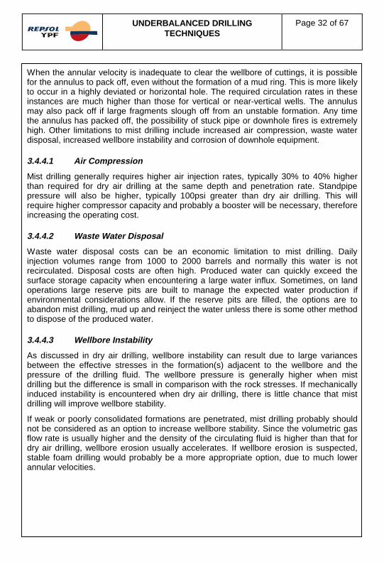
UNDERBALANCED DRILLINGTECHNIQUES
Page 32 of 67
When the annular velocity is inadequate to clear the wellbore of cuttings, it is possiblefor the annulus to pack off, even without the formation of a mud ring. This is more likelyto occur in a highly deviated or horizontal hole. The required circulation rates in theseinstances are much higher than those for vertical or near-vertical wells. The annulusmay also pack off if large fragments slough off from an unstable formation. Any timethe annulus has packed off, the possibility of stuck pipe or downhole fires is extremelyhigh. Other limitations to mist drilling include increased air compression, waste waterdisposal, increased wellbore instability and corrosion of downhole equipment.
3.4.4.1 Air Compression
Mist drilling generally requires higher air injection rates, typically 30% to 40% higherthan required for dry air drilling at the same depth and penetration rate. Standpipepressure will also be higher, typically 100psi greater than dry air drilling. This willrequire higher compressor capacity and probably a booster will be necessary, thereforeincreasing the operating cost.
3.4.4.2 Waste Water Disposal
Waste water disposal costs can be an economic limitation to mist drilling. Dailyinjection volumes range from 1000 to 2000 barrels and normally this water is notrecirculated. Disposal costs are often high. Produced water can quickly exceed thesurface storage capacity when encountering a large water influx. Sometimes, on landoperations large reserve pits are built to manage the expected water production ifenvironmental considerations allow. If the reserve pits are filled, the options are toabandon mist drilling, mud up and reinject the water unless there is some other methodto dispose of the produced water.
3.4.4.3 Wellbore Instability
As discussed in dry air drilling, wellbore instability can result due to large variancesbetween the effective stresses in the formation(s) adjacent to the wellbore and thepressure of the drilling fluid. The wellbore pressure is generally higher when mistdrilling but the difference is small in comparison with the rock stresses. If mechanicallyinduced instability is encountered when dry air drilling, there is little chance that mistdrilling will improve wellbore stability.
If weak or poorly consolidated formations are penetrated, mist drilling probably shouldnot be considered as an option to increase wellbore stability. Since the volumetric gasflow rate is usually higher and the density of the circulating fluid is higher than that fordry air drilling, wellbore erosion usually accelerates. If wellbore erosion is suspected,stable foam drilling would probably be a more appropriate option, due to much lowerannular velocities.

UNDERBALANCED DRILLINGTECHNIQUES
Page 33 of 67
When water-sensitive shales are encountered during dry air drilling, the shalesnormally dehydrate and slough into the wellbore. During mist drilling, the water in thedrilling fluid can chemically hydrate the shales causing them to swell, creating anundergauged hole and potentially wellbore instability. The addition of salts or polymerscan inhibit shale hydration but these additives can add considerable costs to the well. Ifshale hydration is causing significant problems, it may become cost-effective to switchto a conventional drilling fluid system. In some areas, operators have run anintermediate casing string to isolate water producing zones and then continue with dryair drilling.
3.4.4.4 Corrosion
When mist drilling, the potential for rapid corrosion of downhole equipment increasesdue to the high oxygen concentration in the aqueous phase, which encouragescorrosion of exposed steel. Anodic regions, which are more prone to corrosion, arecreated when the rotating drillstring impacts against the hole wall and the casing. Anyoxide film that forms on exposed steel tends to be removed by impact and by theerosive action of the cuttings in the return flow, allowing corrosion to proceedwithout hindrance.
Protection against downhole corrosion can be obtained with the addition of a corrosioninhibitor to the injected water or the foaming agent. The corrosion inhibitor must becompatible with the foaming agent and with any other chemicals added to the injectedwater. Many of the foaming agents used in mist drilling are anionic therefore anioniccorrosion inhibitors are required. Of those readily available, complex organo-phosphateesters are the most widely used and successful in mist and foam drilling applications.Film forming inhibitors, the most commonly used in liquid systems, are not usuallysuccessful in mist or foam drilling.
The bottom hole circulating temperature monitored during mist drilling is higher thanwhen drilling with a conventional drilling fluid and is higher than the calculatedgeothermal temperature. This must be considered when specifying the temperaturerange for the corrosion inhibitor. If the bottom hole static temperature is close to theupper limit of the corrosion inhibitor, it is likely that there will be corrosion while drilling.
3.4.4.5 MWD/FEWD
The same limitations utilising conventional MWD tools experienced in air drilling areevident in mist drilling. If it is necessary to have real time downhole measurementswhile drilling, EM MWD tools or comparable will be required.
3.4.5 Summary
Mist drilling is generally a technique used when, during dry air drilling, a water influx isencountered. The liquid injection allows for the introduction of surfactants andcorrosion inhibitors. The surfactant in the mist helps to unload any liquids in thewellbore caused by a moderate influx of water. This method inhibits the formation ofmud rings and minimises the danger of downhole fires, while also preventing stuckpipe incidents.

UNDERBALANCED DRILLINGTECHNIQUES
Page 34 of 67
3.4.5.1 Advantages
The advantage of using mist drilling, instead of dry air drilling, is prevention of mudrings. The aqueous phase in the circulating fluid saturates the cuttings and thesurfactant in the foaming agent prevents the cuttings from adhering together downhole.The thermal capacity is increased which decreases the chances of igniting anyhydrocarbons present.
The following advantages are in comparison to conventional drilling fluid systems.Some of the other underbalanced drilling techniques, like dry air and gas, may be moreadvantageous than mist drilling:
� High penetration rates, low bit cost and reduction in rig time
� Low water requirements
� No mud removal
� Modest additives cost
3.4.5.2 Disadvantages
The disadvantages of mist drilling, in comparison with dry air or gas drilling, are:
� Increased air compression required
� Wellbore instability, both mechanically and chemically induced
� Corrosion of downhole equipment and waste water disposal
� Cost of extra additives to control some of the above disadvantages
All of these disadvantages add cost to the overall operations. These are some of thereasons why mist drilling is usually not planned from the start but instead used onlywhen necessary.
3.4.5.3 Design Criteria
Underbalanced drilling with mist, a two-phase flow consisting of a discontinuous liquidin the gas, should be considered only when water influx becomes a problem. Mistdrilling should only be used in slight to moderate water influxes. In the event that aheavy water inflow is encountered then consideration should be given to using a foamunderbalanced drilling technique.

UNDERBALANCED DRILLINGTECHNIQUES
Page 35 of 67
3.5 STABLE FOAM DRILLING
Stable foam was originally used as a circulation medium to clean out production sandin depleted wells. It was discovered that stable foam had a carrying capacity up to tentimes greater than common drilling mud. Thus the industry began to utilise foam as adrilling medium for drill-in applications, drilling in lost circulation zones, coil tubingdrilling and underbalanced drilling in depleted zones.
The principal reason for stable foam drilling is the ability to lift large amounts of waterfrom the well without requiring excessive air rates and pressures. Foam allowsunderbalanced drilling without the high erosion velocities of air drilling while providingsimilar ecological advantages. It improves borehole stability with some hydrostaticsupport for the formation without creating a balanced or overbalanced situation.
3.5.1 Foam Drilling versus Dry Air Drilling
Foams incorporate a continuous liquid phase which forms a cellular structure thatentraps a discontinuous gas. Foams normally have a remarkably high viscosity. Theviscosity of foam is greater than either the liquid or the gas they contain. At the sametime, their effective density range is from 1.6ppg to 6.5ppg. This combination of highviscosity and low density can provide several benefits to drilling operations incomparison to dry gas or mist drilling:
� The high viscosity yields efficient cuttings transporting. Therefore, annular velocitiesand required gas injection rates are much lower than in air drilling
� Low density of foam allows underbalanced conditions in most situations. Bottomhole pressure with foam tends to be higher than air drilling and may potentiallyreduce the rate of penetration. However, the rate of penetration is normally greaterthan those attained with a conventional drilling fluid
� Higher annular pressures can essentially reduce the mechanical instability of thewellbore
� Low annular velocities reduce the possibility of erosion of the wellbore or thedrillstring
While it is possible to make foam with a number of gases, air is the most commonlyused. The liquid phase is invariably aqueous. Because this liquid phase is continuous,a foam formed with air will not normally permit combustion of produced hydrocarbons.In many instances air foams are used to put out hydrocarbon fires. One of the greatestbenefits of foam as an underbalanced drilling fluid is its capability to lift large quantitiesof produced liquids. When the volume of a water influx is greater than the capacity ofmist drilling to efficiently remove the liquids, foam provides the ability to continuedrilling underbalanced.

UNDERBALANCED DRILLINGTECHNIQUES
Page 36 of 67
3.5.1.1 Physical Properties of Foam
A foam is made up of an assemblage of gas bubbles in a continuous liquid matrix. Purewater cannot form a foam, since any bubbles blend as soon as they contact oneanother. A surfactant in the liquid phase stabilises the films that form the bubble wallsand allows the foam structure to persist. There are several terms utilised to describefoams. These terms are bubble shape, quality and texture.
Foams are classified according to the shape of the bubbles contained in the foam.Sphere foams are ones which contain very small bubbles that are spherical in shapeand are usually freshly generated. This type of foam generally has the highest liquidvolume fraction. Polyhedron foams consist of bubbles in the shape of a polyhedron.Polyhedron foams contain a lower liquid fraction than sphere foams due topacking geometry.
The quality of a foam is its gas volume fraction expressed in per cent. A low qualityfoam or wet foam contains more liquid than does a high quality foam called a dry foam.If foam quality exceeds an upper threshold level, the liquid phase becomesdiscontinuous and breaks down into a mist of dispersed droplets. A stable foam upperlimit is not clearly defined, and depends on shear rate. The upper limit is alsodependent upon the composition of the liquid phase, such as surfactants, viscosifiersand liquid. The lower limit of stability is simply a question of definition based on thedesignation of a ‘lightened fluid’ or a stable foam.’ It has been defined between 55%and 75%. The range used in drilling is 60% to 99% depending on the characteristics ofthe foam and the location, whether at surface or downhole.
The texture of a foam is described by the size and distribution of its bubbles. A finefoam has small bubbles and a coarse foam has large bubbles. A sphere foam isgenerally a low quality, fine foam. A polyhedron foam is usually a high quality,coarse foam.
Foams are categorically unstable, yet low quality sphere foams tend to decay slowerthan do coarse polyhedron foams. There are two processes that cause the foams todecay. These are thinning of the bubble walls and growth of large bubbles at theexpense of smaller ones.
Thinning of the bubble walls is due to gravity. Bubbles tend to rise to the top of thefoam and the liquid drains through the bubble walls to the base of the foam. Eventuallythe walls will become so thin that they rupture. Stirring a low quality sphere foam toredistribute the bubbles can prevent thinning. However, agitation of a high qualitypolyhedron foam will accelerate rupture of the thinned bubble walls.
Liquid surface tension inside a bubble tends to cause the bubble wall to collapse. Thiseffect has a tendency to be balanced by the gas pressure inside the bubble.This pressure is inversely proportional to the bubble size. When a large bubblecontacts a smaller bubble, the higher gas pressure inside the smaller cell causes thegas inside it to diffuse through the liquid separating the two bubbles, until the smallerbubble is fully absorbed by the larger.

UNDERBALANCED DRILLINGTECHNIQUES
Page 37 of 67
The stabilisation of foams can be accomplished by augmenting the strength of thebubble walls and by retarding the drainage of liquid via the bubble walls. Surfactantsare not only used to create the bubbles, but also to strengthen the bubble walls againstdisproportionate thinning. Proteins used in the liquid phase of an air foam will react withoxygen at the air-liquid interface to form a skin. Drainage can be diminished byincreasing the bulk viscosity of the liquid phase. Additionally, drainage is reduced usingsurfactant mixtures to increase the surface viscosity of the base fluid.
3.5.1.2 Foaming Agents
Surfactants are the principal agents used to generate foams. Not all surfactants willperform as foaming agents. Some tend to destabilise the foam structure and aretherefore used as defoamers. Currently the most widely used foaming agents areammonium salts or alcohol ether sulphates. These are anionic surfactants that arehighly soluble in most liquids. They create a foam that has a very good thermal stabilityand is extremely well adapted to low surface temperatures but they tend to be costly.Other and less expensive anionic foaming agents operate well in fresh water and areresistant to hydrocarbon contamination. On the other hand, they lose their foamingcapabilities in brine and cannot endure low surface temperatures.
Cationic surfactants are not common foaming agents used in drilling operations due topoor stability and the high level of concentrations required. Nevertheless, cationicsurfactants may be worth considering to drill water-sensitive shales because of theirability to stabilise clays.
In general there are three main influences on foam stability. The concentration of thefoam, contamination and temperature all effect the stability of the foam. Increasing theconcentration of the foaming agent will increase the stability of a foam. Measuring thehalf-life of the foam helps determine the foam stability. The half-life of the foam willincrease in direct proportion to the concentration of the foaming agent in normal drillingconcentrations. If the foam is contaminated with brine or hydrocarbons, stability can besignificantly reduced. The third important influence on stability is temperature. Astemperature increases, the rate of foam decay increases and as temperature downholeincreases, it is necessary to increase foaming agent concentration.
3.5.2 Equipment and Material Requirements
3.5.2.1 Surface Equipment
Equipment used to drill with pre-formed foam is the same as that utilised for dry air ormist drilling. The following summarises the additional equipment essential for stablefoam drilling.

UNDERBALANCED DRILLINGTECHNIQUES
Page 38 of 67
� Compressors: The gas phase of the foam is most often provided by aircompressors. Air rates used in foam drilling are usually lower than those for dry airor mist drilling. This allows the use of fewer or smaller compressors. Exceptionsmay occur if an annular back pressure is applied, if jets are run in the bit or adownhole motor is used. If a large water influx is encountered or if liquid has to beunloaded from the wellbore, higher surface pressures will be required. It isrecommended that when using low delivery pressure compressors a booster beincluded in the system
� Gas: The most commonly used gas in foam drilling is air. Other gases could beused such as nitrogen, natural gas, carbon dioxide or exhaust gas. Generally,compressed air is the least expensive. However, the relatively low gas ratesrequired for foam drilling can reduce the additional cost of these alternatives.Whichever gas is used, adequate volume and pressure is obviously essential
� Base Fluid: The liquid mixing tanks and injection pumps are similar to those used inmist drilling. Normally two 10bbl mixing tanks are required. The liquid injectionpump is fed from one tank, while mixing fresh liquid in the other. A higher capacitypump than that used for mist drilling may be required for foam drilling. Typically theliquid rates for foam drilling are in the magnitude of 10gpm to 20gpm, althoughrates of up to 100gpm have been recommended for efficient hole cleaning in deep,large diameter wells. Due to the serious impact of foam quality on hole cleaning, itis essential that adequate metering of the gas and liquid is provided. A flow meter inthe mist pump suction line is recommended
� Foam Generator: A foam generator is the one fundamental addition to aconventional dry air or mist drilling compressor system recommended for foamdrilling. This generator ensures that the two phases are thoroughly mixed. The mostcommon type is positioned where the gas and liquid flows meet. The liquid isintroduced into the gas flow through a small bore tube midpoint in the flow path.The mixture is then directed through a venturi-type flow constriction. Another type offoam generator is located downstream from where the two phases meet. Thispromotes mixing through baffle plates or even sand beds. It is not unequivocallyapparent that a foam generator is required. However, there is evidence that surfacegenerated foam is more tolerant of contaminants, like formation water orhydrocarbons, than a foam formed in their presence. Thus, it is more advantageousto use a foam generator, unless there are specific reasons not to use this type ofequipment
� Portable Units: An alternative to traditional dry air drilling equipment is portable airfoam units. There are a number of custom-built portable units available fromvarious manufacturers. These units are primarily designed for completion andworkover operations but some have adequate output for foam drilling operations.They generally contain air compressors, booster, divided mixing tank, liquidpumps, foam generators and metering system
� Mud Pumps: It is recommended that mud pumps are incorporated into the systemallowing liquids to be pumped into the well immediately if downhole conditionsrequire it. An ample amount of kill weight mud should be held on location

UNDERBALANCED DRILLINGTECHNIQUES
Page 39 of 67
� Drillstring: Non-return valves, either flapper or float valves, are required in thedrillstring. One should be located just above the bit and one near the surface. Whendrilling long intervals, it may be necessary to reposition the upper non-return valveor install another, to minimise the bleed-down time, prior to making eachconnection. The requirement for fire stops should be assessed on an individual wellbasis
� Return System: It may become necessary to pressurise the annulus to control foamquality. For this reason, a choke should be located in the return system in closeproximity to the RCH or RBOP. If the well programme indicates that annular backpressure may be required, then the additional pressure should be included whenspecifying the pressure capacity of the RCH or RBOP. In cold regions it is possiblefor the foam returns to freeze and plug the lines. If possible, an additional foamdischarge line should be added. The discharge line and foam discharge line shouldlead to the flare facility. It is normal to discharge the returns into a combined flareand reserve pit. Since the discharge volumes are likely to be larger than thoseduring air or mist drilling, the pit must be of adequate size, and arrangements madeto handle excess amounts of return waters
� Air Separator: When fluid recycling is desired, a bowl shaped vessel with a chimneystack, referred to as the air separator, is placed at the end of the line above theshakers. The separator permits the majority of the air to escape and preserveswater. Care should be taken that the air separator does not overflow
� Defoaming Equipment: When a foam is correctly formulated, it can have a half-lifeof many minutes or even hours. As a result, large volumes of foam can quicklyamass at the surface when circulated at typical rates. This can often necessitatethe need to accelerate the decay of the foam once it has returned to the surface.Methods to break the foam at surface are chemical, mechanical, and combinedchemical and mechanical
There is a variety of chemical defoamers available. Selection is based on the foamingagent used and laboratory testing to determine the best defoamer for a particularsystem and the necessary concentrations to break the foam.
Defoaming is also possible by mechanical means. If a high quality foam is used, it issometimes sufficient to agitate the foam, thereby rupturing the bubble walls. If a lowquality sphere foam is used, any agitation can actually increase the half-life of the foamby reversing any gravity induced phase segregation. Centrifugal forces can acceleratethe drainage of the liquid phase, destabilising the foam. There are several availabledefoamer systems, all of which work by some form of accelerated centrifugal motion toassist in gravity induced separation. A hydrocyclone works well and there are twospecially designed types of defoamers. The first is a corkscrew shaped flow path thatcauses centrifugal acceleration. The second is a spinning perforated chamber thatdumps air from the top and fluid from the bottom.

UNDERBALANCED DRILLINGTECHNIQUES
Page 40 of 67
3.5.2.2 Injected Fluid
At a minimum, the injected fluid should include water, a foaming agent, and a corrosioninhibitor. The foaming agent should be chosen to accommodate the predicteddownhole conditions. A method for evaluating foaming agents for foam drillingapplications is provided in API RP46.
� Standard test liquids are fresh water, fresh water with 15% kerosene, 10% brine,and 10% brine with 15% kerosene
� Ten grams (10gms) of silica flour are added to one litre (1 ltr) of test liquid tosimulate the presence of cuttings
� Foam, generated with the specific agent, is used to lift each of the four test liquidsup a 10ft long, 2.5in diameter model wellbore
� Quantity of test liquid collected in 10 minutes, taken at the top of the wellbore,indicates the foaming agent’s suitability for use in saline or hydrocarbonenvironments
� If possible, samples of actual formation fluids and cuttings should be substituted forthe regular test liquids and solids
The foaming agent concentration used in the injected fluid should be formulated bydownhole conditions and the interaction between the foaming agent and any formationfluids that are expected to be encountered. Generally, the concentrations of foamingagents used are in the range of 0.5% to 2%. It is important that the concentration bemodified to attain a level of foam stability that balances good hole cleaning with easydefoaming. Careful evaluation and selection of the corrosion inhibitor is vital to preventsevere corrosion of downhole equipment as depth and temperature increase.All corrosion inhibitors should be tested in the worst projected conditions to ensure thattheir effective limit is not exceeded.
Potassium chloride or other shale hydration inhibitors may also be added. To create a‘stiff foam,’ viscosifiers may be added to the liquid phase. This underbalanced drillingtechnique is called ‘Stiff Foam Drilling’.
3.5.2.3 Environmental Considerations
Almost all surfactants in foaming agents are biodegradable but all the variouschemicals used in the stable foam drilling process must conform to the appropriateenvironmental conditions that apply for the drilling location. If the waste liquids arecontaminated by formation fluids, the disposal of the combined fluids must also complywith the appropriate environmental regulations.
Normally the injected fluids are not recycled. However, if the foam can be successfullycollapsed and the fluid reconditioned to the original specifications, recycling is anoption. If this is possible, the consumable costs can be reduced by as much as 50%.

UNDERBALANCED DRILLINGTECHNIQUES
Page 41 of 67
3.5.2.4 Defoaming Arrangements
During foam drilling operations, a very large volume of foam can rapidly accumulate atthe surface. It is standard practice to take measures to destabilise the foam. Thisprocess can be done by chemical or mechanical means or a combination of both.Due to the very large volume produced it is therefore essential that the defoamingarrangements are suitable for the planned well conditions to be encountered.A contingency plan should also be developed to address any failures of the defoamingequipment or changes in the volume of foam produced.
3.5.3 Operating Procedures
Stable foam drilling is similar to dry air drilling in many cases.
3.5.3.1 Hole Cleaning
It is essential that the standpipe pressure and the foam quality at the flare pit is closelymonitored. Mud rings seldom form during foam drilling so the changes in standpipepressure and foam quality usually indicate influx. If the foam is wet and there is anincrease in standpipe pressure this indicates a potential water influx, the downholequality may be too low to lift any produced drill cuttings. Additional concentration offoaming agent will be required. With high volume water influxes, additional air volumemay also be required. If surface foam quality is too high, the foam may slug or revert tomist, which indicates a potential gas influx. In this case the rate of addition of thefoaming agent must be increased but the concentration of the foaming agent must notbe adjusted. A change in surface foam quality without a pressure increase can be afunction of temperature or contamination. This will require an adjustment in foamingagent concentration or rate of addition.
Either a water influx or a gas influx will drive the foam out of its effective quality rangeand reduces the foam's ability to lift cuttings. Also, excessive drag or fill may indicate aproblem with foam quality or annular velocities. These problem must be addressed toavoid a stuck pipe incident.
3.5.3.2 Connections
Connections during foam drilling are handled similarly to connections during dry airdrilling. Depending on foam quality and half-life, it may be necessary to circulatebottoms up before making a connection. The process of making a connection involvesstopping the liquid injection, diverting the air flow to the primary jet line and jetting thereturn line while making the connection. A portion of the foam in the well will collapsewhile making the connection. As in air drilling, circulation should be re-establishedbefore picking up out of the slips. The drilling process can then continue when thestandpipe pressure starts to decrease or when stable foam returns are resumed.

UNDERBALANCED DRILLINGTECHNIQUES
Page 42 of 67
3.5.3.3 Tripping
Before tripping, it is important to circulate the well clean. During the trip, the foam willcollapse and leave all cuttings and liquids at the bottom of the well. The requirementsbefore making a trip are dependent on several factors. The amount and type of influx,and the quality and efficiency of the foam should be established prior to formulating atrip plan. A low quality foam will leave drill cuttings in the well, and the level of fillencountered will provide an understanding of the cleaning efficiency of the system.The circulating system should be adjusted, foaming agent concentration, etc to cleanthe well before a trip.
A small influx may make it desirable to blow the well dry with air before tripping as thiswill reduce the amount of water that must be dealt with tripping back to bottom. A highvolume water influx can fill a substantial portion of the wellbore and will require stagingback into the hole to clear the water. In contrast to dry air drilling, the option exists touse a low quality foam to clear the wellbore in one stage. A gradual increase in foamquality as the well unloads allows for the well to be unloaded in a single stage andconverted back to high quality foam without excessive standpipe pressures.
The presence of a gas influx can present a real danger to the rig. If there is anypossibility that the well has been producing gas, the RCH or RBOP should be used toisolate the well, while the system is flushed to remove the gas. Any gas should beflared. The blind rams should be closed whenever the pipe is out of the hole.
3.5.4 Limitations
There are a number of factors that limit the applicability of stable foam drilling. Theseinclude corrosion of downhole equipment, wellbore instability, downhole fires, wastewater disposal and consumable costs. Most of these limitations are common to airdrilling and to mist drilling.
3.5.4.1 Wellbore Instability
Stable foam drilling improves wellbore stability by removing cuttings at a much lowershear rate than air or mist drilling. The high viscosities and low velocities create littleerosion in the wellbore. Mechanically induced wellbore instability, such as hole collapseor sloughing, is reduced by foam over air by reducing the pressure differential betweenthe rock and the wellbore. The magnitude of the decrease in differential would beapproximately 30% at 5000ft based on typical hydrostatic pressures. In some casesthis may be enough to reduce or eliminate the sloughing.
Chemical instabilities, like shale swelling, caused by any water bearing fluid canusually be controlled by the addition of inhibiting salts. Stable foam carries aproportionally higher cost for the salts than mist drilling due to its higher water content.A water influx can make the cost prohibitive due to treatment of large amounts of waterthat must be disposed of once it reaches surface.

UNDERBALANCED DRILLINGTECHNIQUES
Page 43 of 67
3.5.4.2 Waste Water Disposal
The primary reason for using a stable foam system is to lift formation water from thewell. Due to the large quantities of water that can be expected, specific arrangementswill have to be implemented for disposal of the water. Poor planning for disposal andanticipated water volumes can create a situation where it is necessary to change theunderbalanced drilling technique or in the worst case revert to a conventionaldrilling fluid.
3.5.4.3 Downhole Fires
The air in a stable foam is isolated and unavailable for combustion. In fact, air basedfoams are used in firefighting. The only reported cases of downhole fires with a stablefoam system have been reported in horizontal wells. It is suspected that the foam in thehorizontal section separated and created a continuous air phase that couldsupport combustion.
3.5.4.4 Corrosion
Factors that affect the corrosion caused by foam drilling are the same as mist drilling.The combination of oxygen and water at elevated temperature and the removal ofcorrosion products create a situation that is ideal for rapid corrosion. The addition ofsalts from the formation water or added as shale inhibitors accelerate the corrosion.In the presence of hydrogen sulphide the reduced thickness of the corroded steel ismore susceptible to stress cracking than undamaged steel. This problem can beaddressed by the use of carefully chosen corrosion inhibitors, hydrogen sulphidescavengers and the use of sour service materials.
3.5.5 Summary
When a significant water influx is expected or when wellbore erosion or wellborestability is identified as a potential problem, the stable foam underbalanced drillingtechnique should be investigated as a possible solution. As with all underbalanceddrilling techniques, the basic criteria still apply to candidate selection but some complexproblems associated with other underbalanced drilling techniques are workable with afoam system.
3.5.5.1 Advantages
The stable foam system can handle large influxes of water or gas with propermonitoring and treating facilities. The system creates significantly less wellbore erosionthan either dry air or mist systems. The wellbore stability is also improved using thestable foam technique.

UNDERBALANCED DRILLINGTECHNIQUES
Page 44 of 67
3.5.5.2 Disadvantages
The stable foam system can create a corrosion problem similar to the mist system. Inaddition, the stable foam system is more expensive to treat than the mist systembecause the total water content of the stable foam system is significantly increased.
3.5.5.3 Design Criteria
A well that generally fits the underbalanced drilling criteria and has either largeanticipated water influx or critical wellbore stability problems that could potentiallybenefit from the stable foam system.
3.6 STIFF FOAM DRILLING
3.6.1 Stiff Foam Drilling versus Stable Foam Drilling
Stiff foams are an adaptation of the stable foam concept and were developed fordrilling very large diameter holes (64in) underbalanced. A stiff foam is very similar to astable foam but with additional viscosifying agents added to the mix water. By addingbentonite, polymer, or both, a foam can be constructed that is stable at qualities above99.5% with increased lifting capacity compared to stable foam systems. The stiff foamsurfactants, corrosion inhibitors and stabilisers can be used in the same concentrationsas the stable foam. The higher viscosity and quality exhibited by stiff foams allowfor reduced consumable requirements and reduced flow rates when compared tostable foams.
The rheological properties of stiff foams depend on both the composition of the liquidphase and the quality of the foam. There are two general effects that can be identifiedin the rheology of stiff foams. A stiff foam can be expected to exhibit three to four timesthe viscosity of a stable foam of the same composition, without the addition of polymer.It is heavily influenced by polymer concentration. The second general effect is that theviscosity ratio of a stiff foam is reduced as the quality increases. This effect means thatas the quality of a stiff foam decreases, the associated viscosity decrease is less than itwould be with an equivalent stable foam. This feature makes stiff foams more tolerantof water influxes because the viscosity does not drop as much for the same reductionin quality, and the initial quality of the stiff foam can be higher than a stable foam.
At present there are no predictive models for calculating circulating pressures for stifffoam systems. However, the surface pressures experienced when using stiff foamsappear to be very similar to that of stable foam systems. The pressure increaseexpected due to higher viscosity is offset by reduced flow rates, therefore it isreasonable to use the pressure profiles generated for stable foam systems.

UNDERBALANCED DRILLINGTECHNIQUES
Page 45 of 67
3.6.2 Equipment and Material Requirements
3.6.2.1 Surface Equipment
Equipment used to drill with stiff foam is the same as that utilised for stable foamdrilling. Air requirements for stiff foam drilling are very low and may actually requirefewer compressors than that specified for a stable foam drilling system. As in all airbased drilling, the compressor system must have the pressure capacity to unload awater influx from the well. Fluid injection rates for stiff foam drilling are lower thanstable foam drilling. Requirements for fluid injection specified for stable foam drillingare more than adequate. The only additional requirement for stiff foam drilling is thecapacity to mix the viscosifying agent. The circulating system should be set up to mixboth the amounts and types of materials used in the fluid so, in most cases, this is nota problem. If a special air drilling rig is contracted, it is essential to ensure that the righas the capacity to mix, store and transfer a minimum of 60bbl/hr of viscosifying agent.
3.6.2.2 Injected Fluid
A typical stiff foam system is comprised of a polymer mixed in the 50 to 80 sec/qtrfunnel viscosity range with the foaming agent, corrosion inhibitor and shale inhibitoradded. The injected fluid would normally be mixed in bulk without the foaming agent,then transferred to the injection tanks for the addition of foaming agent and subsequentinjection into the gas phase stream. Chemical concentrations are the same as stablefoam systems. Most viscosifying agents will form a stiff foam but the most commonare the polymers hydroxyethyl cellulose (HEC), polyanionic cellulose (PAC) andcarboxymethyl cellulose (CMC). The CMC system exhibits good calcium and chloridescontamination resistance.
Stiff foams have a longer half-life than stable foams and the half-life increases with theliquid viscosity phase. This can create problems at surface and may require a superiordefoaming system and larger surface pits.
3.6.3 Operating Procedures
Stiff foam drilling is identical to stable foam drilling with the following differences.
3.6.3.1 Injected Fluid Mixing Considerations
The base fluid without the addition of the foaming agent is much more difficult to mixthan non-viscosified fluids. If bentonite is used, it should be prehydrated and anyadditional polymers must be mixed slowly and sheared thoroughly. Most circulatingsystems are designed fairly well for the use of bentonite or polymers but it is essentialthat a polymer shearing unit is included to eliminate any mixing problems. Thenecessary quantity and storage of fluids required each day, including contingencies,must be addressed during the well planning stage.

UNDERBALANCED DRILLINGTECHNIQUES
Page 46 of 67
3.6.3.2 Recognition of Influxes
The indications and effects of an influx into a stiff foam are very similar to stable foamdrilling but there are some differences. A stiff foam is normally run at higher quality andlower rates than stable foams and therefore a gas influx will have a greater effect onthe stiff foam system because gas affects smaller amounts of foam and the stiff foamhas a smaller margin for increased quality. The advantage of using a stiff foam is theincreased lifting capacity at lower foam quality levels. An example would be whendrilling below a gas influx, with additional liquid injected to maintain returns, the lowquality stiff foam from the bit to the gas influx has greater lifting capacity than a stablefoam at the same quality. This could potentially allow drilling to continue below a gasinflux where a stable foam would not carry the drill cuttings between the bottom of thewell and the gas influx.
In the event that a water influx is encountered, the viscosifying agent can also beadjusted to improve hole cleaning. Depending on specific well conditions it may bemore cost-effective to increase the viscosifying agent concentration rather than foamflow rate.
3.6.4 Limitations
3.6.4.1 Gas Influxes
Gas influxes, as noted earlier, are not tolerated well by stiff foams. An aggressiveresponse to a gas flux is necessary to avoid the foam collapsing in the borehole and itis essential to closely monitor the foam quality between the bottom of the well and thegas entry point in order to assess the lifting capacity of the stiff foam prior to mixingwith the gas influx.
3.6.4.2 Corrosion
Factors that affect the corrosion caused by foam drilling are the same for stable foamand stiff foam. The same solutions exist but cost must be considered in the overallplan.
3.6.4.3 Waste Water Disposal
The primary waste water consideration when evaluating the benefit of a stiff foamsystem is the effect of the viscosifying agent on the disposal of the waste water. Thiscould make reinjection of the water impossible or could have a significant effect ondisposal costs. This must be thoroughly examined during the well planning stage inorder to consider recycling and to establish the appropriate disposal method.

UNDERBALANCED DRILLINGTECHNIQUES
Page 47 of 67
3.6.4.4 Formation Damage
If an underbalanced condition is maintained, formation damage is not a concern.However, if the formation is ever in an overbalanced condition, the viscosified fluidused in stiff applications could potentially be more damaging than a simple surfactantfluid used in stable foam applications. This must be addressed during the well planningstage and the appropriate test conducted to evaluate the effect of an overbalancedcondition as a contingency measure.
3.6.5 Summary
Stiff foam systems offer additional benefits to successfully drill underbalanced whenconditions are not conducive to other methods of underbalanced drilling.
3.6.5.1 Advantages
In cases where hole cleaning is a potential concern, such as large diameter hole, stifffoams should be considered. In cases of known water influxes or contamination of thefoam system is expected a stiff foam system should be considered.
A stiff foam improves wellbore stability by removing drill cuttings at lower shear ratesthan a stable foam system. The higher viscosity and lower flow rates create littleerosion in the wellbore. In addition, the air in a stiff foam is isolated and unavailable forcombustion. The added stability of a stiff foam makes it less likely to separate in ahorizontal well, and the lower flow rates make it more feasible to switch to an inert gasif necessary.
3.6.5.2 Disadvantages
If run at very high qualities, a stiff foam system can be susceptible to collapse due to agas influx. However, the quality of a stiff foam can be adjusted and the effects of thegas influx can be compensated. The liquid fraction of a stiff foam system is moreexpensive than a stable foam system but stiff foams require less liquid. Stiff foams canbe very difficult to break at surface and are more likely to form stable emulsions withproduced fluids than a stable foam.
The polymers necessary for a stiff foam substantially increase the cost of drilling. Thiscost can be partially or fully offset by reduced requirements for water, compressors,and chemicals.
3.6.5.3 Design Criteria
Large diameter holes with anticipated hole cleaning problems, water influxes orcontamination problems are situations where stiff foam drilling should be considered.

UNDERBALANCED DRILLINGTECHNIQUES
Page 48 of 67
3.7 GASIFIED LIQUIDS
Use of gasified or aerated liquids is one of the oldest underbalanced drillingtechniques. The ability to vary the gas fraction and change the density of the drillingfluid medium has significant advantages over dry air, mist or foam systems which allowvery little control over the drilling fluid medium density. Gasified liquid technology wasprimarily developed to combat lost circulation problems. It has become an effectiveunderbalanced drilling technique with the development of computer programmes tocalculate the effective bottom hole pressure. These programmes allow a controlleddrawdown or underbalanced condition to be maintained to avoid formation damagefrom overbalanced fluid invasion or from fines migration due to uncontrolled flowrate.Gasified liquid drilling normally uses effective fluid densities in the 4.0ppg to 7.0ppgrange. The base liquid is usually non-viscosified water or crude oil aerated withnitrogen, air or even natural gas. Since the primary component of the system is liquid, itis more likely that nitrogen is economical and also eliminates the inherent problemsassociated with air and water mixtures.
3.7.1 Gasification Concepts
Gasification of the liquid is accomplished either at surface through the drill pipe, ordownhole via several possible flow paths. Drill pipe injection allows for the lowestbottom hole pressures. Annular injection will normally provide the desired reduction inbottom hole pressure, however this will be at the expense of increased gas injectionbut will allow the utilisation of MWD mud pulse telemetry. If possible, some form ofannular injection is usually desirable.
3.7.1.1 Gasification Techniques
� Drill Pipe Injection: The gas phase is added at surface to the drilling fluid medium.This technique provides the deepest gas injection and lowest bottom hole pressurebut it does not allow for continuous MWD operation. The initial cost of thistechnique is low as no additional equipment is required and the required gasvolume to function the system is less than the other techniques. The cost savingsmust be contrasted with longer connection times from bleeding down the drillstring,less reliable bottom hole pressure information and limited ability to use MWD
� Annular Gas Injection: The gas phase is added downhole. Annular gas injectionallows for accurate bottom hole pressure calculations and the use of conventionalMWD systems. Several paths are possible for annular gas injection. In most casesthe cost of the annular gas injection technique will be higher for equipment inconjunction with the requirement for higher gas volumes. Some operational costsavings will occur by eliminating the requirement to bleed down the drillstring.Annular gas injection can continue during connections and even during trippingoperations which ensures that the required underbalanced condition can bemaintained at all times when drilling sensitive formations

UNDERBALANCED DRILLINGTECHNIQUES
Page 49 of 67
� Parasitic String: Jointed or coiled tubing parasitic strings can be run and cementedbehind the casing string with an injection sub close to the casing shoe. This optioninvolves additional equipment cost and additional operational time. Due to theinstallation technique the parasitic string is not recoverable
� Parasitic Casing: A parasitic casing string can be temporarily hung off inside theintermediate casing string in a similar manner to a scab liner. The advantage of thissystem is that the parasitic casing is recoverable but the technique involves hang-off equipment. The problems associated with parasitic casing are restricted holediameter and the possible wellhead height or access
� Through Completion: In the event that a gas lift system is available and operational,the gas lift system can be used with no additional equipment cost. This system isconsidered to be the best option because of limited equipment cost, no reduction inhole size and no additional wellhead height requirements. The gas lift system couldbe operated on natural gas, nitrogen or air
3.7.1.2 Liquid Phase
The liquid phase in gasified liquid drilling is normally water, brine, diesel, crude oil orcondensate. A water influx makes it uneconomical to use a conventional drilling fluiddue to the high cost of reconditioning the drilling fluid. The liquid chosen should be asnon-damaging as possible to avoid formation damage in the event that overbalanceconditions occur. Viscosified fluids are normally avoided due to emulsion and foamingproblems at surface as well as additional potential for formation damage. The primaryfluid-related problems which should be addressed during the well planning stage arethe formation of emulsions between the formation fluid and drilling fluid medium,foaming of the returns on surface, monitoring the active concentration of additives andthe separation of the three-phase system at surface. These problems can be handledwith a minimum of planning but are exacerbated by the addition of viscosifying agents.
3.7.1.3 Gaseous Phase
The gas phase can be air, nitrogen or natural gas. Air is inexpensive but carries the riskof corrosion problems and, in horizontal wells, downhole fires. In a gas lift well, naturalgas may be a viable option if surface facilities are available to handle the gas. The bestoption is cryogenic nitrogen, if economically viable. Utilising air as the gas phasecarries all of the potential problems as discussed in Section 3.1. Both the problems ofcorrosion and downhole combustion must be considered against any calculatedeconomic advantage. Membrane produced nitrogen, or nitrogen produced at therigsite, contains 5% oxygen so downhole combustion is not considered a problem butcorrosion is considered to be a problem. Natural gas is normally considered to be a firehazard but if the well will be producing gas, it may be the best option available with theaddition of gas busters and/or separators.

UNDERBALANCED DRILLINGTECHNIQUES
Page 50 of 67
3.7.2 Equipment and Material Requirements
3.7.2.1 Surface Equipment
� Gas Injection System: Gas equipment will be specified as discussed in earliersections. Once the gaseous phase is chosen, refer to the appropriate section ofthe manual
� Parasitic Tubing String: A parasitic tubing string can be jointed pipe or coiled tubing.The string should be clamped to the casing to ensure integrity when the casing isrun
� Parasitic Casing String: The effective hole size that can be drilled through theparasitic casing string should be assessed with respect to the functionality of thewell. Consideration should be given to addressing the problem associated with thehang-off method and wellhead height necessary to accommodate the parasiticcasing string
� Liquid Injection: The rig circulating system will handle the liquid injectionrequirements. It is essential to check the minimum pump rates required against theminimum pump capacity of the rig. The low pump rates may require small liners andpistons out with the provisions of the contract
� BOP Stack: BOP requirements will depend on local regulations and operationalconsiderations. With no anticipated high pressures, an RCH and a standard BOPstack may be sufficient. At higher pressures an RBOP and the capability for ram toram stripping may be necessary
� Return System Configuration: In a low pressure limited production scenario thereturns can be routed from the RCH to a flare pit and the settled water transferredback to the circulating system. If an expensive fluid is used, the returns can flow toa mud gas separator (MGS) with the liquid being routed to the shale shakers andthe gas to the flare pit. In a high production and/or a high pressure scenario isanticipated, an emergency shutdown system (ESD) will be necessary on the returnline and an MGS or, in the case of crude oil or condensate production, an oil/waterseparator will be required. The separator system could vary from a simple skimmerto a full closed system with three-phase separation
� Surge Tank: When using aerated liquids as the drilling fluid medium, a surge tankshould be utilised. This piece of equipment will prevent the air from blowing water orthe liquid phase out of the system. This tank can also assist in the separationprocess. Downhole pressures and surging can be further controlled by placing aback pressure control choke at the surge tank

UNDERBALANCED DRILLINGTECHNIQUES
Page 51 of 67
3.7.2.2 Downhole Equipment
Consideration should be given to BHA geometry to allow for stripping in and out of thewell. Drillstring floats or hydrostatic control valves (HCV) are required as in allunderbalanced drilling. The requirement for a surface drillstring float depends on thegas injection point. If pure liquid is in the drill pipe a surface float is not necessary.If liquid is in the drillstring, an HCV may be required to hold the column of fluid and notallow any ingress of air into the drill pipe. The HCV is a spring loaded check valve thatholds enough backpressure to stop the fluid in the drill pipe from falling and allowing airto be drawn into the drillstring. Without an HCV there is a danger of a downhole fireand the MWD cannot communicate until any entrained air is circulated past thetelemetry cartridge of the MWD system.
3.7.2.3 Instrumentation
The instrumentation required for gasified liquid underbalanced drilling is dependent onthe primary purpose of choosing this particular technique. If lost circulation is theprimary concern and formation damage is not a concern, the extra expense forsophisticated monitoring systems is probably not justified and the instrumentation usedfor dry air drilling is sufficient. However, in the event that formation damage is critical,direct downhole pressure measurement may be an option with an MWD system or asophisticated surface monitoring system. The downhole pressure measurements willbe used by a computer model to calculate effective bottom hole pressure, flowconditions and indicate the presence of any influxes.
There are several preparatory systems available that monitor all available surfaceinformation including the composition of the return flow. The computer model will beused to predict the pressure losses of the complete circulating system and will modelinflux rates.
3.7.3 Operating Procedures
3.7.3.1 Controlling Bottom Hole Pressure
The bottom hole pressure (BHP) is controlled by varying the gas and liquid injectionrates. If maintaining the correct bottom hole pressure is critical, an MWD system and/ora surface computer modelling facility will be necessary. In the event that the bottomhole pressure is friction controlled, an increase in gas injection rate will increase thebottom hole pressure. If the bottom hole pressure is hydrostatically controlled, anincrease in the gas injection rate will decrease the bottom hole pressure.

UNDERBALANCED DRILLINGTECHNIQUES
Page 52 of 67
3.7.3.2 Connections
The process of making a connection varies depending on the criticality of maintainingthe underbalanced condition and the type of gas injection being used. With annularinjection, connections are rapid and simple because the gas injection may continueand the drill pipe may be full of fluid. With drillstring injection, the gas injection processmust be stopped which causes an increase in the bottom hole pressure. To reduce theconnection time the drill pipe can be filled with fluid to the upper non-return valve, bleddown quickly but this will create a spike in the bottom hole pressure as the slug ofliquid is circulated around the well. The drill string can also be displaced to gas beforemaking a connection. This will also reduce bleed-down time and result in a lowermaximum bottom hole pressure than displacing the drillstring with fluid to the topnon-return valve.
3.7.3.3 Tripping
Prior to commencing a trip, a trip plan should be developed which will depend on theamount and type of flow from the well. In most cases the pipe will be stripped from thehole as in other underbalanced drilling and may need to be staged back in to bottom.The trip plan should also address any contingency measures as appropriate.
3.7.4 Limitations
The limitations inherent to gasified liquid drilling are high formation pressures orproductivity, wellbore instability, bottom hole pressure control, produced water,corrosion and penetration rate. In all of these limitations except penetration rate,gasified liquids are better suited to handle the problems than other underbalanceddrilling techniques.
3.7.4.1 Controlling Bottom Hole Pressure
Controlling bottom hole pressure is difficult with a gasified liquid due to unstableconditions caused by connections and trips. Careful planning and the ability to controlfluid densities through a significant range can offset or eliminate problems with BHPcontrol that cause transient overbalance or excessive underbalanced conditions.Establishing a maximum and minimum allowable BHP provides a framework to planoperations.
3.7.4.2 Water Influx
Produced water can be tolerated in large amounts by a gasified liquid system. Twopotential problems involving water influx are hole cleaning below the influx and ECDvariations in the wellbore. If a large water influx requires increased gas injection and/ordecreased fluid injection, problems may be encountered cleaning the hole below theinflux. This could require increasing liquid viscosity to lift cuttings and cause problemswith emulsions, foaming and/or separation problems at surface.

UNDERBALANCED DRILLINGTECHNIQUES
Page 53 of 67
A situation can arise where the ECD on bottom, where the gas is compressed, cancause lost circulation while at the same time a shallower zone is flowing, due to lowerECD caused by the expanded gas lightening the fluid in the shallower section of thewell. In some cases circulation cannot be established under these conditions even withdry air injection. The only options are to run casing or drill with no returns.
3.7.4.3 Gravity Invasion
While horizontal drilling with gasified liquids, or flow drilling, it is possible to lose fluid tothe formation while the well is flowing. Gravity invasion is the process of liquid runninginto the macroporosity on the low side of the hole while the well is flowing.
Figure 3.6 - Gravity Invasion Effects
N o Invas ion A tTop o f H o le
GRAVITY INVASION
Sm all F ractu reH ig h Ve loc ityN o Invas ion
D rill P ipe
F orm ation F lu ids
3.7.4.4 Penetration Rate
Gasified liquid drilling will typically produce penetration rates higher than conventionaldrilling fluids and lower than gas, mist or foam drilling. The penetration rate is usuallyrelated to pressure hence average fluid density will be the controlling factor. In weakformations, the overall penetration rate is often not the achievable rate but thesustainable rate. In this case there will be little variation between any systems from airto mud. In some areas it is not possible to run maximum bit weight in the surface holeand the penetration rate is limited by cuttings transport either in the wellbore or thesurface equipment. In this case penetration rates are similar regardless of the drillingsystem utilised.

UNDERBALANCED DRILLINGTECHNIQUES
Page 54 of 67
3.7.5 Summary
Gasified liquid drilling can be tailored to the specific requirements of a well.
3.7.5.1 Advantages
� Allows the underbalanced status to be designed rather than set by the drillingtechnique due to the use of fluids with various densities
� Gasified liquid underbalanced drilling is more tolerant of pressure and influxes thanother methods discussed
� Provides much more mechanical support for the wellbore than other methodsdiscussed
� Gasified liquids provide the highest BHP of the methods and are the most likely tobe able to drill high pressure or high flowrate formations without reaching theproduction limits of the surface equipment
� The higher BHP exerted by gasified liquids provides support for mechanicalinstability in the wellbore and allows the successful drilling of less competentformations than other forms of underbalanced drilling. Mechanical instability may bea problem when drilling through overpressured shales to reach depleted reservoirs.Water-sensitive shales are more susceptible to swelling using a gasified water thana lighter or water-free system. Gasified hydrocarbon fluids or shale inhibitors willcontrol this problem
3.7.5.2 Disadvantages
� The value of the underbalanced regime is less than other methods discussed
� There is a smaller gain in penetration rates as compared with other systems
� As in any water/air system, corrosion can be a major problem. If it is impractical touse cryogenic N2 as the gas phase, then apply the same corrosion precautions asfor mist or foam drilling
3.7.5.3 Design Criteria
In wells with high pressure or high influx rates gasified liquid provides more control ofthe BHP. In weak formations, additional wellbore stability is achieved by the increasedeffective density of the system. With annular injection, standard MWD technology canbe applied for directional control and pressure monitoring.

UNDERBALANCED DRILLINGTECHNIQUES
Page 55 of 67
3.8 FLOW DRILLING
3.8.1 Flow Drilling Concept
The terminology ‘flow drilling’ is used to describe drilling underbalanced with a liquidsystem rather than a drilling fluid medium with a gas fraction. In some cases theformation pressure is higher than the drilling fluid medium pumped, and the well is in aflow pressure regime from the lack of hydrostatic pressure exerted by the drilling fluidmedium. In other cases the drilling fluid medium is above kill weight and hydrocarbonflow from the formation effectively creates an underbalance condition in the well on theannulus side of the flow path. In either case, pumping liquid at surface and maintainingunderbalanced conditions downhole is referred to as flow drilling.
3.8.1.1 Underbalanced Condition
In some cases, where the formation pressure gradient is above an available fluidgradient, production casing is set above the target interval and drilled out with a mudweight below the formation pressure. This is often used for underbalanced horizontaldrilling to eliminate formation damage during the long exposure of drilling fluid to thehorizontal section.
When the drilling fluid is above the formation pressure gradient, nitrogen can be usedto initiate flow from the reservoir. Once the well starts flowing, the nitrogen is stoppedand the influx maintains the underbalanced conditions.
A method under development for incompressible lightened fluid is the addition ofhollow glass spheres to the fluid. An 8.8ppg polymer mud can be reduced to circa6.5ppg with the addition of 40% glass spheres. At present this method is probably noteconomical but it does provide a future path for low weight, incompressible fluids.
In some fractured reservoirs, the fracture system will cause lost circulation when thereservoir is penetrated. As the hydrostatic pressure falls, the well will start producing oiland gas and come on production. The Pearsall Field in the Austin Chalk, Texas, USAis an example where this method is used. It is also possible to kick off the well afterpenetrating the top of a formation using gas and then flow drill the remainder ofthe well.
3.8.1.2 Drilling Fluid Medium
The drilling fluid medium selected must maintain the wellbore pressures between thezero underbalanced condition or balanced pore pressure and minimum pressureallowed by the wellbore stability. Normally, non-damaging non-viscosified fluids areused to avoid formation damage from periodic overbalanced conditions and to reducesurface handling problems caused by emulsions, foams, and poor or slow separation.In some cases, like large hole or long horizontal sections, it may not be possible toclean the hole properly with non-viscosified fluids.
One consideration that could preclude choosing hydrocarbon-based fluids is theirability to carry dissolved gas. In cases where gas is dissolved in fluid, large pressuresurges can be experienced.

UNDERBALANCED DRILLINGTECHNIQUES
Page 56 of 67
3.8.2 Equipment and Material Requirements
3.8.2.1 Surface Equipment
� BOP Stack: A standard BOP stack with the addition of an RCH or RBOP is used inmany flow drill operations. The standard configuration consists of, from the bottom,a double outlet spool blind rams, pipe rams, annular ram, double outlet spool, andthe RBOP. An additional set of pipe rams below the blind rams and an additionaldouble outlet spool between the blind rams and the annular are frequently addedfor more flexibility and redundancy
� Rotating Control Head versus Rotating BOP: The RCH has been used verysuccessfully on many wells but has limitations and drawbacks. The RCH tends todevelop low pressure leaks with minor amounts of wear due to the design of theelement. The API does not recognise the RCH as a BOP component and themanufacturing companies do not rate them with regard to pressure containment.There is no facility to monitor the wear on the RCH and the life expectancy cannotbe predicted
The RBOP is a pressure rated BOP component, with a two level closing system thatprevents catastrophic failure when used within rated limits. They are commonlyavailable with API approval from 1500psi working pressure and 2000psi operatingpressure limit. Units with a higher pressure rating, typically 2500psi workingpressure and 5000psi operating pressure limit, are available
� Choke Manifold: A dual choke manifold, nominal 4in ID, with a bypass is usuallysufficient for flow drilling operations. The facility for isolating and replacing pluggedor cut out chokes is included in most large choke manifolds and therefore can beused in a flow drilling application. The true open flow area which varies for the samesize chokes from different companies must be considered during the selectionprocess. In the event that a high flow rate will be used or extended periods ofcirculation are anticipated, all the 90° bends and flow tees should be targeted withlead to prevent erosion
� Mud Gas Separator: The requirement for an MGS varies depending on wellconditions. On a low productivity and a low GOR well, a gas buster is sufficient.However, where anticipated well conditions include a high gas rate well withhydrogen sulphide, a closed system including three-phase multistage separationmay be necessary. An MGS design must be selected for individual well conditionsbut a 6in diameter by at least a 12ft tall atmospheric MGS with a 6in flare line and alarge liquid sump will be sufficient for most flow drill applications. The flare lineshould be either run to a large flare pit or be an adjustable height stack capable ofsafely flaring all potential gas returns
� Oil/Water Separation and Storage: Oil/water separation without hydrogen sulphideis normally accomplished in an open skimmer system with the water being returnedto the circulating system. In high flow situations the returns may go through a three-phase separator and have a skimmer system to further clean the water beforereturning it back to the circulation system. The oil collected is either transferreddirectly to an existing production system or pumped to a storage tank fortransportation

UNDERBALANCED DRILLINGTECHNIQUES
Page 57 of 67
Figure 3.7 - Flow Drilling Surface System for 3-Phase Flow (No H 2S in gas phase)
G as Buster
C hoke m an ifo ld
In -line
H e a te r
R B O P
B O P
S ha leS hakers
O ilS to rage
T ank
S k im m erT ank
M udT ank
M ud P um p
F la reS tack
N itrogenU n it
3.8.3 Operating Procedures
3.8.3.1 Controlling Bottom Hole Pressure
The primary difference in operating procedures between normal (overbalanced) drillingand flow drilling is that control of the well is maintained at surface rather than at theformation. The objectives are to maintain control of the well while avoiding formationdamage, differential sticking and lost circulation. To achieve these goals it is desirableto design the operations to have as few interruptions as possible in circulating the wellwhile holding positive pressure differential from the formation to the wellbore.
All pressure limitations must be firmly established during the planning of the well andcontingencies written for specific cases to eliminate any delays dealing with changesthat are observed while drilling. The options of changing fluid densities, varyingcirculating rates and imposing surface pressures should all be clearly defined beforestarting the well.
Initially the returns will be routed directly to the shaker and the annulus will bemaintained at atmospheric pressure. When formation fluid inflow starts, the returns willbe directed through the choke manifold then to the surface separation system.The separation system should be sized to handle any instantaneous flowrates from thewell. These instantaneous rates or slug flow can be much higher than the potential ofthe well for continuous flow. If the well approaches the maximum surface system rate, itwill have to be choked back and changes in fluid density or drilling style made toreduce the flowrate.

UNDERBALANCED DRILLINGTECHNIQUES
Page 58 of 67
3.8.3.2 Connections
Connections are similar to any underbalanced drilling method. Any drill pipe pressure isbled down to the top non-return valve and the connection made.
3.8.3.3 Tripping
Tripping depends on the observed and predicted surface pressures. If the pressure istoo high or is expected to rise to an intolerable level during the trip, the annulus can beslugged with a heavier fluid. If annulus pressures rise toward the safe limit during thetrip, this can be repeated. Before logging or tripping, it may be desirable to circulate thewell to a lower amount of underbalance to avoid repeatedly pumping the annulus andpossibly overbalancing the formation. Be aware that with the formation balanced oroverbalanced the rise of gas will still increase the surface pressures and create asituation where it is natural to pump more kill weight fluid even after the formation isoverbalanced. These conditions have occurred in many cases where the projectedproductivity increase was not achieved even though ‘the well was never overbalanced.’It is therefore essential to understand the pressure regime in the well at all times.
3.8.3.4 Additional Operations
Once the well has been drilled underbalanced, logging and completion operationsshould be performed underbalanced. The casing must be run underbalanced and thecompletion performed underbalanced. The well should be perforated with as muchunderbalance as is reasonable.
3.8.4 Limitations
The flow drilling technique cannot be used in situations where high annular pressuresare anticipated, the formation pressures are not adequately defined and wellboreinstability has been identified as a potential problem.
3.8.4.1 High Annular Pressures
High annular pressures, whether during a trip or caused by choking back the well whiledrilling, must be controlled within the specified limits of the well programme. The firststep is to decide if there is an error in the calculated fluid densities or in the drillingmethod. It may be necessary to limit the ROP whilst drilling the reservoir interval toavoid having the gas/liquid ratio increase too rapidly as drilled gas lightens thehydrostatic column, more than projected, and increases influx. The well should bechoked back and circulated from close to bottom as possible. The annular pressurecan then be increased by either choking back the well or increasing the drilling fluidmedium density to maintain the desired underbalanced condition. However, excessivesurface choking can cause the breakdown of shallower formations.
Circulating time is not significant when compared to damaging the well by not fullyunderstanding the problem. It is essential that the objectives of drilling the well areclearly understood and the procedures included in the well programme addressall contingencies.

UNDERBALANCED DRILLINGTECHNIQUES
Page 59 of 67
3.8.4.2 Uncertain Formation Pressures
Flow drilling is poorly suited to areas where the formation pressures throughout thewellbore are not adequately defined or where there is a transition zone in the open holesection. When dry air drilling, the wellbore is always underbalanced but when flowdrilling at or near the formation pressure gradient it is possible to be overbalanced andunderbalanced in the same wellbore.
Example 1: A well is flow drilled through a depleted zone and into a sand unitcontaining gas. Lost circulation is encountered in the depleted upper zone and all thecirculated drilling fluid medium and the flow contribution from the sand unit is lost to thedepleted zone. This condition is known as an underground blowout. If drilled with aconventional drilling fluid, the depleted zone would undoubtedly have developed agood filter cake, the sand unit containing the gas would have been overbalanced, andthe well would not have encountered these problems.
Example 2: A well is flow drilled through an aquifer sand unit above the target in aninfill underbalanced drilling program. The previous wells were drilled conventionally inan overbalanced regime and the aquifer sand unit was not identified, but it is nowflowing because of the low density drilling fluid medium in the wellbore. The target ispenetrated and the flowrate from the well decreases and eventually stops because thecombined flowrate is too high for the drilled gas to lighten the drilling fluid medium, andhence achieve an underbalance regime. Nitrogen is used to gas lift the well, withoutknowing that a large volume of water is flowing into, and damaging the target zones.The drilling operation is completed however after the completion is installed, theproduction rate is much lower than expected for drilling the well underbalance.
3.8.4.3 Wellbore Instability
Flow drilling, in most cases, provides more borehole support than most underbalanceddrilling methods and therefore drilling weaker formations is more viable than with othersystems. Unconsolidated or very weak formations can readily produce more solidsdebris than a producing interval produces fluids, and so borehole sloughing, erosion orcollapse is always a concern. It is essential that a problem zone is identified during thewell planning stage so that the zone can be cased off before flow drilling commencesor drilling overbalanced may be necessary.
3.8.5 Summary
3.8.5.1 Advantages
Flow drilling allows for underbalanced drilling without the equipment or problemsassociated with gas compression and handling. It is conducive to using conventionalMWD equipment and provides a very flexible system for achieving a specifiedunderbalance regime while drilling. In most cases, flow drilling exhibits similar corrosionrates to those observed during overbalanced drilling. Flow drilling also eliminatesdownhole combustion problems associated with dry air drilling.

UNDERBALANCED DRILLINGTECHNIQUES
Page 60 of 67
3.8.5.2 Disadvantages
As in all underbalanced drilling, well control, borehole stability and surface handlingcan become problems and must be studied during the well planning stage. Appropriatesteps can then be taken to reduce the problems encountered while drilling.Hole cleaning in large holes or horizontal sections can be a problem and requiresviscosifying agents. The associated problems of emulsions, foam and separation willhave to be considered and economically factored into the decision of whether to usethe flow drill method.
3.8.5.3 Design Criteria
Areas that exhibit lost circulation problems, significant formation damage and/orwellbore instability that does not allow for other types of underbalanced drilling aregood candidates for flow drilling. Any well that appears to be suited for underbalanceddrilling but falls short of the criteria for the other methods should be considered forflow drilling.
3.9 MUDCAP DRILLING
Mudcap drilling is a technique that has been developed to continue drilling when flowdrilling develops two conditions. Firstly, surface pressures or flowrates that are inexcess of the safe operating limits of the RBOP or other surface facilities. Secondly, ifthe use of kill weight fluid results in lost circulation. This situation does not allow normaldrilling to continue, thus mudcap drilling provides an alternative method.
3.9.1 Overview
This technique is a method of controlling lost circulation and well control that couldallow the completion of a well that is not progressing as planned. This is not technically‘flow drilling’ because the well does not flow to surface but the equipment used for flowdrilling is applicable and it could be a choice in certain circumstances while flow drilling.
One example of this situation would be an underground blowout where circulation islost below a productive interval and the hydrostatic pressure necessary to limit theflowrate from the productive interval is lost. This leads to an uncontrolled flow situationwhere there is lost circulation and an uncontrolled flow concurrently. This situation canoccur whilst using conventional drilling fluids but usually leads to massive lostcirculation and kill operations, and drilling is not continued.
In cases where lost circulation and influxes are expected and the hydrogen sulphidelevels are too high then mudcap drilling may be planned to avoid bringing the hydrogensulphide to surface. Switching to mudcap drilling as soon as the returns are lost, stopsthe majority of formation fluids from being in the wellbore until the well is completedand is no longer a major safety concern.

UNDERBALANCED DRILLINGTECHNIQUES
Page 61 of 67
The basic idea is to pump fluid into the annulus to effectively reduce the annuluspressure and then drill with water or brine with the return flowline closed. Where thedrill cuttings go is often open to speculatation, but several successes have beenachieved using this method in fractured reservoirs and lost circulation zones. In onefractured carbonate reservoir, mudcap drilling is actually a planned drilling system. Inmost cases, mudcap drilling is used when no other alternatives exist.
3.9.2 Summary
3.9.2.1 Advantages
In an extremely productive interval there is often a very small pressure change betweena lost circulation situation and well flowing conditions. If density of the drilling fluidmedium is raised then lost circulation is encountered, and if density is lowered an influxoccurs. With a high reservoir pressure, the well may not be drillable due to thelimitations of the RBOP using the flow drilling technique. Mudcap drilling may allow thewell to be drilled and cased where any other system would require abandoningthe prospect.
3.9.2.2 Disadvantages
This method of drilling does not provide cuttings or little, if any, reliable formation data.Furthermore, the potential for a stuck pipe incident is extremely high.
3.9.2.3 Design Criteria
There is a limited number of mudcap drilling applications because the basic techniquenormally does not achieve the goals of the drilling programme. A prospect with highpressure, high levels of hydrogen sulphide, potential loss circulation, formation damagefrom conventional drilling fluids or a slimhole environment may be a good candidate formudcap drilling. Even in this case it is unlikely that injecting huge volumes of fluid andall the drill cuttings from the lower section of the hole would result in less formationdamage. This has been the case in a fractured carbonate where the injected solidswere acid soluble, and were subsequently treated, and abandonment was the onlyother alternative.
3.10 CLOSED SYSTEMS
3.10.1 Closed System Concept
Many underbalanced drilling operations utilise an open return system that is adaptedfrom standard rig equipment with only minor necessary additions. In some cases wherea production system is in place, and the projected drill cuttings volume is very small,the returns are directed into the production system, either directly or through achoke manifold.

UNDERBALANCED DRILLINGTECHNIQUES
Page 62 of 67
Closed systems combine the advantages of both methods of handling returns. In aclosed system all fluids are fully contained until the drilling fluid medium is pumpedback to the circulation system surface handling system. The gas can be flared, the oilcollected for sales, and any hydrogen sulphide in the system is safely contained. If theoxygen content of the returns can be maintained below the lower explosive level (LEL)usually about 8%, the closed system provides the safest operation, the most control,and the best information on the well. Figure 3.8 is a four-phase closed systemwith optional nitrogen injection and a returns heating system in addition to thestandard system.
Figure 3.8 - Underbalanced Drilling Closed System
4-PhaseSeparator
C hoke m an ifo ld
In - line
H eater
R BO P
B O P
C utting sS tora ge
M udT ank
M ud P um p
F la reS ta ck
P roduc tionT ank
N itrogenU nit
3.10.2 Equipment and Material Requirements
� Return Flowline: The return line should be of large diameter and will allow forthe following:
� Divert the return flow to the shale shakers, separator or directly to flare pit
� Flow through the rig choke manifold or through a larger drilling choke manifold
� Be equipped with an emergency shutdown valve (ESD) valve and manualshut-in valve
� Have the same pressure rating as the BOP upstream of ESD
� Be equipped with a sample catcher
� Have lead targeted tees and ninety degree elbows where applicable

UNDERBALANCED DRILLINGTECHNIQUES
Page 63 of 67
The return line may contain high pressure, four-phase, high velocity flow and mustbe designed to handle more than the projected rates. It is a large choke line, not areturn line in the normal sense of drilling, and must be designed and maintained assuch. This is a critical link to the overall safety of the system
� Flow Control Manifold: A flow control manifold should be used in addition to the rigchoke manifold. This manifold is similar but with larger valves and piping. The flowcontrol manifold is the primary flow path with the rig choke manifold as a back-upsystem. This is a good location for the addition of a sample catcher
� Cuttings Filter: The cuttings filter is a pressurised vessel designed to drop out themajority of the cuttings into a removal system, like a Moineau pump, then pass thegas, oil and water to a separator. This allows the use of a three-phase separator forprimary separation. A four-phase separator, if available, takes the place of thecuttings filter and the three-phase separator
� Heater: Produced gas in the presence of water can form gas hydrates. Thisnormally occurs at a pressure drop where the gas expansion refrigerates the flowstream. The formation of hydrates can plug lines and valves downstream of aprimary pressure control device and cause pressures to exceed the rating of thedownstream equipment. A simulation should be performed to predict the formationof hydrates. If any chance exists for the formation of hydrates there should be an in-line heater installed to raise the flowing temperature enough to prevent theformation of the hydrates
3.10.3 Operational Procedures
Operating a closed system requires more monitoring than an open system.All pressures and levels must be maintained for safe efficient operations. Plugging ofequipment is more likely than in an open system and more difficult to correct.The items unique to closed system drilling that require special attention are:
� Separator levels must be monitored at all times
� Liquid and solid discharges should be recorded to provide well information
� Separator pressure must be maintained to achieve proper separation but theseparator must be kept below its rated working pressure
� The flare line can be used to regulate the separator pressure with a backpressure valve
� Any plugging should be immediately corrected, while flowing through contingencyequipment, if possible, or with the well shut in
� The flare must be lit or have a pilot light at all times
� Wall thickness should be monitored in critical flow areas
� If injecting any oxygen, the separator must be monitored for LEL and purged withnitrogen when necessary

UNDERBALANCED DRILLINGTECHNIQUES
Page 64 of 67
3.10.4 Limitations
The limitations of closed system drilling are pressure, gas composition in the flowstream, availability of people and equipment, and costs.
3.10.4.1 High Surface Pressures and Flowrates
Care should be taken to ensure that the surface system will be capable of handling thepressures and flow rates that will be experienced during drilling and completionoperations including any contingency plans. The possibility of plugging must beconsidered and appropriate pressure relief valves installed as conditions warrant.
3.10.4.2 Drilling Fluid Medium
If air is to be a component of the drilling fluid medium, pre-job investigation of explosivelimits with mixtures that closely resemble actual conditions should be performed.The accepted lower limit for flammable hydrocarbon and oxygen mixtures is 8% oxygenbut laboratory tests have maintained combustion at 6% oxygen. The presence ofhydrogen sulphide can lower the oxygen level required for combustion. Moreover,hydrocarbon composition has an effect on combustion.
3.10.4.3 Equipment and Personnel Availability
The equipment for closed systems underbalanced drilling is more common in Canadathan the US and the utilisation is growing. It could be difficult to find equipment andcrews in this fairly new and expanding market.
3.10.4.4 Operating Cost
Additional costs associated with closed systems underbalanced drilling must becarefully considered. There is a large difference in required crew levels and inoperating and repair costs depending on the system contracted. A fully automatedsystem with the appropriate erosion control measures fitted may only require oneoperator and very few repairs. A much cheaper unit may require several operators andmay require periodic shutdowns during drilling for repairs and washouts.
The apparent day cost is high for a closed system underbalanced drilling operation.The project cost can be higher or lower depending on savings from pit construction andreclamation, location size, surface damages, etc. Operationally, the closed system canreduce unproductive time by allowing for less circulating time controlling the well withina limited pressure and flow window.

UNDERBALANCED DRILLINGTECHNIQUES
Page 65 of 67
3.10.5 Summary
3.10.5.1 Advantages
The advantages of closed system drilling are:
� Safer than open system, if oxygen is not introduced into the system
� Allows accurate measurement of gas, liquid and solids from the well
� More environmentally acceptable than a reserve pit
� Creates a smaller footprint, which may be critical in re-entry or offshore drilling
� Allows for production testing without additional rig-up
� Image benefit due to improved safety and environmental concerns
3.10.5.2 Disadvantages
The primary disadvantages in closed system drilling are:
� Daily equipment and operating costs are higher. Note that pit construction on land,location reclamation and drilling efficiency can easily offset this cost
� Is not safe if oxygen is present in the drilling fluid medium, as explosive limits canbe reached in surface vessels
3.10.5.3 Design Criteria
� In wells where hydrogen sulphide is anticipated
� High productivity or high pressure wells
� Limited workspace
� The need for well information during and after drilling
� When pit construction and reclamation costs are high
� When safety concerns dictate
� When environmental considerations are critical

UNDERBALANCED DRILLINGTECHNIQUES
Page 66 of 67
3.11 SNUB DRILLING
Snub drilling is an underbalanced drilling operation which uses a snubbing unit as thepressure control system. The snubbing unit is designed to operate pipe under live wellpressure conditions and allows the drilling operations to be performed safely with muchhigher surface pressures than with a conventional drilling rig.
3.11.1 Snub Drilling Concept
Snub drilling is an option where underbalanced drilling is desirable but the wellconsiderations preclude the use of a conventional drilling rig as the primary drilling andpressure control system. The snubbing BOP system can safely operated with wellheadpressure from 5000psi to 15,000psi.
The snubbing unit can strip in and out of the hole conventionally under low pressuresconditions. If high surface pressures are encountered, the snubbing unit has theadditional capacity for ram to ram stripping operations and can snub the drill pipe intothe well when the weight of the drillstring is insufficient to overcome the upwardpressure force.
In high pressure operations, there is always concern that the drillstring can be forcedout of the hole once pressure overcomes the weight of the drillstring or being unable torun in against the upward pressure force. Killing the well can damage the formation andnullify any gains previously made drilling underbalanced.
A snubbing unit allows the well to be flowed or shut in during connections and trips andeliminates one potential cause of formation damage. When conventional drilling rigruns casing underbalanced, it is normal operating practice to partially kill the wellbefore commencing the casing job. During the course of tripping and running casing itis very likely that the formation will be in an overbalanced regime at some time, forexample by surge pressures. Snubbing casing into a well is an option to avoid thissituation and could potentially increase the final well productivity.
3.11.2 Summary
A snubbing unit is designed for pressure control more so than a conventional drillingthan a rig. This can have a large impact on personnel and rig safety as well as a largeimpact on final well performance. Using a snubbing unit allows some decisions to bemade based on what is best for the well, by reducing the requirement to contrast alldecisions with limited excess capacity at surface for additional pressure.
Many wells have been damaged by controlling the surface pressure too much tomaintain a safe margin below the capacity of the surface equipment. By increasing thesafe pressure handling capacity by a ratio of three to six times more it may becomepossible to concentrate on maintaining an underbalanced condition and still operatewell below any pressure restrictions. Additional well production should justify theextra expense.

UNDERBALANCED DRILLINGTECHNIQUES
Page 67 of 67
3.11.2.1 Advantages
Using a snubbing unit has the following advantages:
� Improves rig safety both with equipment and training
� Provides options not available to a conventional drilling rig
� Reduces the potential of formation damage
� Allows drill pipe to be run in and out of the well under very high surface pressure
� Allows casing to be run underbalanced without the formation being overbalanced atsome point during the casing job
3.11.2.2 Disadvantages
A snubbing unit can be more expensive per day than a conventional drilling rig and isslower than a conventional drilling rig during tripping operations. Safety issues and welleconomics must offset the added expense.
The usable drill pipe size can be limited as well as torque limits for drilling. These itemsare not normally insurmountable and a variety of options exist to increase performance.

Drilling and Production Operations Ref: UBDL 04
SPECIAL WELLS M ANUAL, VOLUME II:UNDERBALANCED DRILLING
Issue: Feb 2000
SECTION 4 SUMMARY OF UNDERBALANCEDDRILLING TECHNIQUES
Page 1 of 5
TABLE OF CONTENTS
4. SUMMARY OF UNDERBALANCED DRILLING TECHNIQUES........................... 2
4.1 HARD FORMATIONS ...................................................................................... 2
4.2 SOFT FORMATIONS....................................................................................... 4

SUMMARY OF UNDERBALANCEDDRILLING TECHNIQUES
Page 2 of 5
4. SUMMARY OF UNDERBALANCED DRILLING TECHNIQUES
This section is a tabular summary of underbalanced drilling methods. The first tablegives techniques primarily used for hard, competent and tight formations. The secondtable gives methods used more for softer, more productive formations. The divisions ofgas-based and liquid-based fluids are not strictly correct but are based on drilling fluidmedium densities. The foam systems are fluid, continuous phase systems but havebeen included in the ‘gas based systems’ due to densities.
4.1 HARD FORMATIONS
Hard competent formations can usually be drilled with a gas-based drilling fluidmedium. Dry air, nitrogen, natural gas, stable foam and stiff foam all fall into thiscategory. The common factors are large underbalance pressures and the associatedincreases in the rate of penetration. Frequently these formations will require stimulationso formation damage may not be an issue. Gas-based drilling is often used in upperhole sections to reduce drilling time.

SUMMARY OF UNDERBALANCEDDRILLING TECHNIQUES
Page 3 of 5
Table 4.1 - Hard Formation Guidelines
UNDERBALANCEDDRILLINGMETHOD
STRONGPOINTS
WEAKPOINTS
DESIGNCRITERIA
Dry Air No formationdamage
Intolerant of waterinfluxes
Hard rock
Fastest ROP Danger of downholefires
Lost circulation
Long bit life Wellbore instability Easily damaged targetNo shale swelling Cannot use MWD Good wellbore strengthCan drill withpercussion bits
Cannot drillhydrogen sulphide
Limited ground water
No lost circulation No high pressure orhydrogen sulphide
Uncontaminatedcuttings
ROP sensitive topressure
Nitrogen Same as dry air Same as dry air Same as dry airNo downhole fires Expensive Downhole fire problem
Horizontal well
Natural Gas Same as dry air Same as dry air Same as dry airNo downhole fires Expensive Downhole fire problemCheaper thannitrogen
Fire danger atsurface
Available gas supply
Mist Handles more waterflowEliminates mudrings
Shale problemsHigher air ratesCorrosion
Moderate water inflow
Stable Foam Handles more waterflowImproves liftingcapacityLess wellboreerosionMore formationsupport
Higher additivecostsMust break foamMust dispose ofwaterCorrosion
High water inflow
Wellbore instability
Erosion
Cuttings removal
Stiff Foam Better hole cleaning
Handles more water
Difficult to breakCorrosion
Large holes
Water influxContamination of foam

SUMMARY OF UNDERBALANCEDDRILLING TECHNIQUES
Page 4 of 5
4.2 SOFT FORMATIONS
Softer formations will more commonly be drilled with a fluid-based system, eitherlightened or naturally below the formation pressure gradient. Wellbore stability andformation damage are typically the driving forces behind this style of drilling. Increasedpenetration rate is normally less important and may actually be slower on averagebecause of the smaller percentage of time rotating on bottom.
Gasified liquids and flow drilling fit this category. Mudcap drilling may not actually be‘underbalanced’ but fits better in this category than the first. Snub drilling is typicallyused in high permeability situations where liquid systems are appropriate. Closedsystem drilling can be used in any type of underbalanced drilling and has beenincluded with liquid-based drilling for convenience.

SUMMARY OF UNDERBALANCEDDRILLING TECHNIQUES
Page 5 of 5
Table 4.2 - Soft Formation Guidelines
UNDERBALANCEDDRILLINGMETHOD
STRONGPOINTS
WEAKPOINTS
DESIGNCRITERIA
Gasified Liquid BHP control
Mechanical wellboresupportTolerates influx well
Slower penetrationratesCorrosion
MWD possible
Wellbore instability
High influxLimited underbalance
Flow No compressionequipmentMWD worksLess corrosionGood BHP control
Hole cleaning
Oil/gas handling
Higher pressure
Lost circulationWellbore instability
Mudcap No flow to surface No returnsNo cuttings
No other choiceHigh hydrogen sulphideLost circulation
Snub Higher pressuresCan maintainunderbalance
ExpensiveSlow
High pressuresSevere formationdamage
Coiled Tubing SafetyHigh pressuresEnvironmentallyfriendlyWireline dataFasterLittle washoutFast mob/demob
RotationWeight on bitPull capacity
Expensive
Through tubingShallow slimholeSize restriction
Safety/environmentalFormation damageRemote expensiveoperations
Closed System No pitsSafeAccuratemeasurementsEnvironmentallyfriendlySmall footprint
CostDanger from oxygen
High hydrogen sulphideHigh productivityHigh pressures
Limited work area
Need for information

Drilling and Production Operations Ref: UBDL 05
SPECIAL WELLS M ANUAL, VOLUME II:UNDERBALANCED DRILLING
Issue: Feb 2000
SECTION 5 REFERENCES AND FURTHER READING Page 1 of 5
TABLE OF CONTENTS
5. REFERENCES AND FURTHER READING ........................................................... 2
5.1 REFERENCES................................................................................................. 2
5.2 FURTHER READING....................................................................................... 5

REFERENCES AND FURTHER READING Page 2 of 5
5 REFERENCES AND FURTHER READING
5.1 REFERENCES
(1) Bennion DB, Thomas FB, Bietz RF and Bennion DW: ‘Underbalanced Drilling:Praises and Perils,’ SPEDC (December 1998) as paper No SPE 52889 and firstpublished as paper No 35242 at the 1996 Permian Basin Oil and Gas RecoveryConference, Midland, March 27-29.
(2) Bol GM, Wong SW, Davidson CJ and Woodland DC: ‘Borehole Stability inShales,’ SPEDC (June 1994) and first published as paper No SPE 24975 at the1992 European Petroleum Conference, Cannes, November 16-18.
(3) Brouse M: ‘Economic/Operational Advantages of Top Drive Installations,’ WorldOil (October 1996), pp 63-68.
(4) Cooper SC and Cuthbertson RL: ‘Horizontal, Underbalanced Wells Yield HighRates in Columbia,’ World Oil (September 1998), pp 75-84.
(5) Cox RJ, Li J and Lupick GS: ‘Horizontal Underbalanced Drilling of Gas Wellswith Coiled Tubing,’ SPEDC (March 1999) as paper No SPE 55036 and firstpresented as paper No SPE 37676 at the 1997 SPE/IADC Drilling Conference,Amsterdam, March 4-6.
(6) Cuthbertson RL, Vozniak J and Kinder J: ‘New Surface Equipment forUnderbalanced Drilling,’ Hart’s Petroleum Engineer International (March 1997),pp 67-71.
(7) Ewy RT: ‘Wellbore-Stability Predictions by Use of a Modified Lade Criterion,’SPEDC (June 1999) as paper No SPE 56862 and first presented aspaper No SPE 47251 at the 1998 SPE/ISRM Eurock Conference, Trondheim,July 8-10.
(8) Ewy RT, Myer LR and Cook NGW: ‘Investigation of Stress-Induced BoreholeEnlargement Mechanisms by a Liquid-metal Saturation Technique,’ SPEDC(March 1994) and first published as paper No SPE 21519.
(9) Gas Research Institute: ‘Underbalanced Drilling Short Course Manual’, manualreference No GRI-97/0236.1a.
(10) Gazaniol D, Forsans T, Boisson MJF and Piau J-M: ‘Wellbore FailureMechanisms in Shales: Prediction and Prevention,’ JPT (July 1995) and firstpublished as paper No SPE 28851 at the 1994 European PetroleumConference, London, October 25-27.

REFERENCES AND FURTHER READING Page 3 of 5
(11) Hale AH, Mody FK and Salisbury DP: ‘The Influence of Chemical Potential onWellbore Stability,’ SPEDC (September 1993) and first published as paperNo SPE 23885 at the 1992 SPE/IADC Drilling Conference, New Orleans,February 18-21.
(12) Hodgson RK: ‘Snubbing Units: A Viable Alternative to Conventional Drilling-Rigand Coiled-Tubing Technology,’ JPT (February 1997) and first presented aspaper No SPE 30408 at the 1995 Offshore Europe Conference, Aberdeen,September 5-8.
(13) Last N, Plumb R, Harkness R, Charlez P, Alsen J and McLean M: ‘Brief:An Integrated Approach to Wellbore Instability in the Cusiana Field,’ JPT(March 1996) and published as paper No SPE 36066; additional detail appearsin the extended paper No SPE 30464.
(14) MacDougall GR: ‘Mud/Gas Separator Sizing and Evaluation,’ SPEDC(December 1991) and first published as paper No SPE 20430 at the 1990Annual Technical Conference and Exhibition, New Orleans, September 23-26.
(15) McGregor B: ‘Exploitation of New Underbalanced Drilling Technologies,’World Oil (May 1999), pp 45-47.
(16) Mair R and Meinster M: ‘A Balanced View - Underbalanced Drilling Trend on theRise,’ Euroil (September 1998), pp 26-30.
(17) Moak TW, Prater T, Lagendyk R and Olsen BE: ‘Snubbing Workover ofa Subsea Well Under Pressure Proves Concept,’ World Oil (June 1998),pp 43-50.
(18) Monjure N: ‘Developing Industry Standards for Underbalanced Drilling Systems,’World Oil (March 1999), pp 43-46.
(19) Munro C and Radcliffe P: ‘New System Handles UBD Surface Fluids Offshore,’World Oil (May 1999), pp 57-60.
(20) Ottesen S: ‘Borehole Stability Assessment Using Quantitative Risk Analysis,’first published as paper No SPE 52864 at the 1999 SPE/IADC DrillingConference, Amsterdam.
(21) Purvis DL and Smith DD: ‘Underbalanced Drilling in the Williston Basin,’JPT (September 1998) and first presented as paper No SPE 39924 at the1998 Rocky Mountain Regional/Low Permeability Reservoirs Symposium,Denver, April 5-8.
(22) Santarelli FJ, Zaho S, Burrafato G, Zausa F and Giacca D: ‘Wellbore-StabilityAnalysis Made Easy and Practical,’ SPEDC (December 1997) and firstpublished as paper No SPE 35105 at the 1996 SPE/IADC Drilling Conference,New Orleans, March 12-15.

REFERENCES AND FURTHER READING Page 4 of 5
(23) Saponja J: ‘Challenges With Jointed-Pipe Underbalanced Operations,’ SPEDC(June 1998) and first presented as paper No SPE 37066 at the1996 International Conference on Horizontal Well Technology, Calgary,November 18-20.
(24) Sehnal Z, Ostebo B and Rorhuus K: ‘Extending the Limits of HydraulicWorkover Technology,’ World Oil (June 1997), pp 49-62.
(25) Smith JR: ‘The 1999 LSU/MMS Well Control Workshop: An Overview,’ WorldOil (June 1999), pp 41-45.
(26) Stewart D and Dr Susman H: ‘New Motors Solve UBD and HPHT Problems,’Hart’s Petroleum Engineer International (August 1997), pp 31-34.
(27) Strickland DG and Smith M: ‘Concentric Workovers Successful in a WellRecovery Operation,’ World Oil (June 1997), pp 39-42.
(28) Teichrob RR, Abdul HJ and Butler SD: ‘Reservoir Inflow While DrillingUnderbalanced - A Qualitative Perspective,’ Hart’s Petroleum EngineerInternational (May 1997), pp 37-41.
(29) Vozniak J and Cuthbertson RL: ‘Field Results Document Underbalanced DrillingSuccess,’ Hart’s Petroleum Engineer International (April 1997), pp 71-75.
(30) Vozniak JP, Cuthbertson RL and Nessa DO: ‘Underbalanced Drilling BenefitsNow Available Offshore,’ Hart’s Petroleum Engineer International (May 1997),pp 43-46.
(31) Weiss MW and McLennan J: ‘Underbalanced Operations: AvailableResearch/Training Opportunities,’ World Oil (June 1998), pp 75-80.
(32) Wong SW, Veeken CAM and Kenter CJ: ‘The Rock-Mechanical Aspects ofDrilling a North Sea Horizontal Well,’ SPEDC (March 1994) and first publishedas paper No SPE 23040 at the 1991 Offshore Europe Conference, Aberdeen,September 3-6.
(33) Woodland DC: ‘Borehole Instability in the Western Canadian Overthrust Belt,’SPEDC (March 1990) and first published as paper No SPE 17508 at the1988 Rocky Mountain Regional Meeting, Casper, Wyoming, May 11-13.
(34) Zausa F, Civolani L, Brignoli M and Santarelli F: ‘Real-Time Wellbore StabilityAnalysis at the Rig Site,’ JPT (February 1997) and first published as paperNo SPE 37670 at the 1997 SPE/IADC Drilling Conference, Amsterdam,March 4-6.
(35) Zoback MD and Peska P: ‘In-Situ Stress and Rock Strength in the GBRN/DOEPathfinder Well, South Eugene Island, Gulf of Mexico,’ JPT (July 1995) and firstpublished as paper No SPE 29233.

REFERENCES AND FURTHER READING Page 5 of 5
5.2 FURTHER READING
(1) Zhou S, Hillis RR and Sandiford M: ‘On the Mechanical Stability of InclinedWellbores,’ SPEDC (June 1996) and published as paper No SPE 28176.
(2) Economides MJ, Watters LT and Dunn-Norman S: ‘Petroleum WellConstruction,’ John Wiley & Sons Ltd, Section 6.
(3) Gas Research Institute, ‘Underbalanced Drilling Short Course Manual’, manualreference No GRI-97/0236.1a.