Embed Size (px)
Citation preview
IEEE SIGNAL PROCESSING MAGAZINE, VOL. XX, NO. X, XXXX 2017 1
Perceptual Spatial Audio Recording, Simulation,and Rendering
Huseyin Hacıhabiboglu, Senior Member, IEEE, Enzo De Sena, Member, IEEE, Zoran Cvetkovic, SeniorMember, IEEE, James Johnston Fellow, IEEE, and Julius O. Smith Member, IEEE
Abstract—Developments in immersive audio technolo-gies have been evolving in two directions: physically-motivated and perceptually-motivated systems. Physicallymotivated techniques aim to reproduce a physically ac-curate approximation of desired sound fields by employ-ing a very high equipment load and sophisticated com-putationally intensive algorithms. Perceptually-motivatedtechniques, on the other hand, aim to render only theperceptually relevant aspects of the sound scene by meansof modest computational and equipment load. This articlepresents an overview of perceptually motivated techniques,with a focus on multichannel audio recording and repro-duction, audio source and reflection culling, and artificialreverberators.
I. INTRODUCTION
Since Blumlein introduced the original concept ofstereophonic recording using a pair of “figure-of-eight”microphones, spatial sound technologies have steadilygrown in sophistication, complexity and capabilities.Delivering a convincing illusion of a desired sound fieldrequires finding solutions to several problems lying atthe intersection of physics, psychoacoustics, and engi-neering. First, the relevant sound field information needsto be identified, and methods for its acquisition devised,which amounts to designing an array of microphones.Then, methods for rendering the identified spatial audioinformation in some optimal way need to be developed.This requires the design of a playback system, including
H. Hacıhabiboglu is with the Graduate School of Informatics, Mid-dle East Technical University (METU), Ankara, TR-06800, Turkey.e-mail: [email protected].
E. De Sena was with the Department of Electrical Engineering(ESAT), KU Leuven, Leuven, Belgium. He is now with the Instituteof Sound Recording, University of Surrey, Guildford, UK. e-mail:[email protected].
Z. Cvetkovic is with the Department of Informatics,King’s College London, WC2R 2LS, London, UK.e-mail:[email protected].
J. Johnston is with Immersion Systems, Seattle, WA, USA. e-mail:[email protected].
J. O. Smith is with CCRMA, Stanford University, CA, USA. e-mail: [email protected].
Manuscript received June 30, 2016; revised November 22, 2016
hardware configuration, along with necessary signal pro-cessing algorithms. If the spatial sound field is virtual,as opposed to generated by an actual acoustic event, therequired playback signals need to be synthesized ratherthan recorded. To that end, ideally an accurate approxi-mation of the desired sound field would be computed andthen “recorded” using a virtual microphone array to beplayed via the corresponding actual loudspeaker array;this process is referred to as auralization. However, dueto the very high numerical complexity of sound fieldsimulation methods, typically the auditory perspectiveis first rendered via level differences between pairs ofloudspeakers, and then overlaid by room effects. The pastnine decades of spatial audio reproduction and synthesishas seen innovations and developments in all of thesedirections.
Generating the experience of a spatial sound scenecan be achieved in a number of ways. Comparing dif-ferent methods, at one extreme there are binaural tech-niques [1], which provide a convincing experience overtwo channels, by presenting stereophonic audio cues,that is, interaural time, level and spectral differences,referred to as “ear signals”. Binaural presentations workbest over headphones, however, with cross-talk cancella-tion [2], they can be successfully used also with a pair ofloudspeakers, although the effect is confined to a verynarrow listening area. For a listener who is not static,the auditory illusion can be maintained via head trackingmechanisms combined with the real-time adaptation ofthe binaural signals. The advent of virtual and augmentedreality systems has recently revived interest in binauralsystems. However, some inherent problems of binauralaudio such as individualization remain [3], limiting thespatial quality of the auditory experience they provide.
At the other extreme there are systems that aim to re-construct an accurate physical approximation of a soundfield. Notable examples include wave field synthesis(WFS) [4] and higher-order Ambisonics (HOA) [5].WFS is based on Huygens principle and Kirchhoff-Helmholtz integral, which together state that the soundfield due to a primary source can be exactly synthesizedby infinitely many secondary sources on the surface
IEEE SIGNAL PROCESSING MAGAZINE, VOL. XX, NO. X, XXXX 2017 2
enclosing a reproduction volume. Such a system canachieve a spatially extensive listening area and can beused in large auditoria such as film theaters. Ambisonicsis based on sound field approximation using its sphericalharmonics at the center of the listening area. Higher-order Ambisonics (HOA) is capable of achieving re-sults comparable to wave field synthesis close to thecenter of the reproduction rig. While both WFS andHOA provide elegant solutions to the spatial recordingand reproduction problem, they have high equipmentload requirements, which can reach several hundreds ofcarefully positioned loudspeakers. For this reason, theirapplication domain has so far been confined to specialisthigh-end systems. WFS and HOA can also run on sys-tems with a more practical equipment load by includingperception-inspired corrections. Comprehensive reviewsof WFS and HOA have recently been published [6], [7].
In between these two extremes are systems with fiveto ten channels which are suitable for use in smallto medium size listening rooms. Such systems do notpossess a sufficient number of channels to physicallyreconstruct a sound field in a wide listening area, neitherare they capable of accurately reconstructing the earsignals for listeners in multiple locations. Therefore,they must rely to a large degree on perceptual effects,similar to those used for binaural systems, to generatethe illusion of a desired sound field within not overlyconfined areas.
As with recording and reproduction technologies,there is a variety of techniques for sound field simulation.At one extreme there are physically-motivated methodswhich aim to calculate an approximate solution of thewave equation. For that purpose several numerical meth-ods have been developed that achieve a very high level ofaccuracy. However, they typically have prohibitively highcomputational costs. Examples include finite-differencetime domain (FDTD), finite element method (FEM),and boundary element method (BEM) [8]. While thesemethods lend themselves to parallelization, the associ-ated computational cost is still too high for real-timeoperation at interactive rates and on low-cost devices.
At the other extreme there are methods which tryto render only some higher level perceptual effects.These methods, called artificial reverberators, requireonly a fraction of the computational load associatedwith physically-motivated room simulators and typicallyaim to mimic only certain characteristics of the tail oftypical room impulse responses, such as modal density,echo density, and timbral quality [9]. They do not modelexplicitly a given physical space, but rather are used toobtain a pleasing reverberant effect and have been widelyused for artistic purposes in music production.
In between these two extremes are methods that aimto render a certain physical sound scene, but only modelits most perceptually relevant aspects. Full-blown roomauralization systems typically aim to render each andevery reflection and diffraction up to a given order foreach source [10], [11]. More recent methods achieve re-markable computational savings by rendering accuratelyonly first order reflections, while replacing higher orderreflections with their progressively coarser approxima-tions [12]. Further computational savings are possibleby eliminating sources whenever they are inaudible, aprocess referred to as audio source culling.
This article is concerned with spatial audio systemsand methodologies which substantially rely on psychoa-coustics. We will first present a concise summary ofspatial auditory perception, followed by a brief historyof audio reproduction methods which rely on humanauditory perception. More specifically, an overview ofbinaural audio, stereophony and multichannel audio sys-tems will be given. Then, perceptually-motivated mul-tichannel audio reproduction systems, such as vector-based amplitude panning (VBAP), directional audiocoding (DirAC), perceptual sound field reconstruction(PSR), and their extensions will be reviewed. Finally,application of perceptual knowledge in the contexts ofartificial reverberation, audio source culling and roomauralization will be discussed.
II. SPATIAL AUDITORY PERCEPTION
The primary mechanism which humans use to localizesound sources in the horizontal plane is based on thedifferences between the signals received by the two ears1.Due to the spatial separation between the ears, the soundwave generated by a sound source reaches the two earswith a different delay, called interaural time difference(ITD). Moreover, the sound wave is scattered by thehead causing the level of the signal at the ear furtheraway from the source, contralateral ear, to be reducedin comparison with the level of the signal at the earcloser to the source, ipsilateral ear. This level differenceis called interaural level difference (ILD).
The interaural time delay for a typical human headcan vary between ±750 µs in the acoustic free field.Humans can detect ITDs as low as 10-20 µs at the frontdirection corresponding to about 1◦ in the horizontalplane. Similarly, the ILD is frequency dependent and canbe as high as 21 dB at 10 kHz. Sensitivity to changes
1Psychophysics of spatial hearing has been an active research areafor the past century. Most of the information given in this sectionhas been thoroughly reviewed by Blauert in [13]. Interested readeris referred to this excellent volume for more information and anextensive set of further references.
IEEE SIGNAL PROCESSING MAGAZINE, VOL. XX, NO. X, XXXX 2017 3
in ILD is also frequency-dependent, and for instancefor pure tones it varies between 0.5 and 2.5 dB. Incontrast with ITD which is the primary localization cueat low frequencies, ILD cues are more important in soundsource localization at higher frequencies. This is due tothe low level of scattering at low frequencies when thewavelength is close to or larger than the size of the head.ITD and ILD cues also change with the distance of asound source and the size of the head.
Note that ITD and ILD pairs do not uniquely specifythe source direction. If, for the purpose of illustration, weassume a spherical head, binaural cues will be identicalfor sound sources placed on conic shaped surfaces ateach side of the head. These surfaces are called conesof confusion. In the horizontal plane, sources on theconic section which is the intersection of the horizontalplane with the cone of confusion will have front-backambiguity. Humans can typically resolve this ambiguityby small head movements.
The elevation of a sound source is perceived basedprimarily on the spectral shaping of its signal whichoccurs as a result of the scattering of the sound aroundthe head. This spectral shaping depends on the elevationin a manner which is determined by the sizes andshapes of the pinnae, head and torso. Consequently, thefrequency content of the sound itself also affects theperception of the elevation of its source.
Subjective localization of sound sources involves asignificant level of uncertainty. Localization blur is thesmallest change in the direction of a source that willresult in its perceived direction to change. For sourcesin the horizontal plane, localization blur is generallylower than around 10◦. For sources in the median plane,localization blur in the order of 20◦ can be observed.A related concept is locatedness, which refers to theperception of the spatial extent of a sound source. Thisis an important attribute because the center of mass of asound source can be localized accurately yet the sourcecan still be diffusely located. Two other measures ofspatial resolution of hearing are the minimum audibleangle (MAA) and minimum audible movement angle(MAMA). MAA correspond to the minimum change inthe direction of a static source in order for a listenerto discriminate it as being to the left or to the rightof the original direction. MAMA, on the other hand,is a measure of spatial resolution for moving sources,which quantifies the smallest arc that a moving soundsource must travel to be discriminable from a stationarysource [14].
Perception of the distance of a sound source is bothless reliable and less well-understood than the perceptionof the direction of a sound source. Several cues affect the
perception of distance. Among these, intensity is the onlycue which is inherently related to the sound source andalso the only absolute cue. The other distance cues arerelated either to the environment (direct-to-reverberantenergy ratio, lateral reflections), to the physical proper-ties of the listener (e.g. auditory parallax) or to cognitiveaspects (e.g. familiarity) [15].
An interesting property of distance perception is theoverestimation and underestimation of distance at dif-ferent ranges and for different sounds. Apparent dis-tances of sources far away from a listener are un-derestimated and those closer than around 1-2 m areoverestimated [16]. Familiarity, which is a cognitive cuerelated to prior exposure to and knowledge of the charac-teristics of the sound source, also has a similar effect. Forexample, distance of whispered speech is underestimatedwhile that of shouted speech is overestimated.
An important capability of the human auditory per-ception mechanism lies in its ability to localize sourcesin reverberant environments such as rooms and otherenclosed spaces. This is made possible by suppressingreflections that come immediately after the direct sound.When a broadband impulse and a delayed copy of it arepresented from different directions with a short delayof less than 1 ms in between, a single auditory event2
is perceived at a direction between the directions ofthe two sources, gradually shifting towards the leadingsource as the lag in the time of arrival increases. Thiseffect is called “summing localization” and both sourcescontribute to the perceived direction of the auditoryevent. When the delay is between 1 ms and 5 ms, asingle fused auditory event close to the leading sourcecan be heard. Within this delay range, the presence ofthe lagging source is audible since it changes the timbreof the auditory event, however its direction cannot bediscriminated easily. Above 5 ms, the broadband clickand its echo are perceived as distinct sound events. Thetime delay above which two distinct events are heard iscalled the “echo threshold”. While the classic demon-stration of these effects involve broadband click pairs,different signals will have different echo thresholds. Forexample, the echo threshold can be as high as 20 ms forspeech and music signals.
The effect that the direction of the auditory eventdepends predominantly on the leading source is calledlocalization dominance, whereas the effect that a singleauditory event is perceived when there are two soundevents is called fusion. The effect that the discriminationof the direction of the lagging sound source is sup-
2An auditory event is defined as an event perceived by a listenertypically (but not necessarily) in response to a sound event.

IEEE SIGNAL PROCESSING MAGAZINE, VOL. XX, NO. X, XXXX 2017 4
pressed is called lag discrimination suppression. Thesethree effects are collectively known as the precedenceeffect [17].
Another important binaural cue is interaural coher-ence (IC) which is a measure of the coherence of signalsreceived by the two ears. IC is high for sounds comingdirectly from the source where the two ear signals arehighly correlated and low in the diffuse sound fieldwhere the correlation is low. Therefore, IC provides theinformation about the level of reverberation and thusabout the spaciousness of the environment.
III. HISTORY OF PERCEPTUALLY MOTIVATEDSPATIAL AUDIO
Binaural audio and multichannel stereophony are twoof the most common spatial audio technologies predatingmore recent technologies such as WFS by more thanhalf a century. Binaural audio has found extensive useand has received renewed interest especially for virtualreality applications, while multichannel systems havebeen the de facto standard for home entertainment andautomotive audio systems. Simultaneously, due to thepopularity and market dominance of two-channel audioformats, stereophony which uses two loudspeakers is stillcommonly used.
A. Binaural audio
Binaural audio3 is based on a simple assumption: if thesignals that would be received at the ears of a listener asa result of an acoustic event, are provided to the listenerwith sufficient accuracy, he or she will feel perceive anauditory event which would correspond to the originalacoustic event. These ear signals can be either recordedwith microphones implanted in the ear canals of anartificial human head, such as KEMAR or Neumann KU-100, or synthesized using signal processing methods. Inboth cases, the signals are usually presented over a pairof headphones.
The microphones used for recording binaural audioare also known as “dummy head” microphones and aremanufactured to resemble a typical human head. Theexternal ears of these microphones are typically modeledafter external ears of humans who have exceptional spa-tial hearing acuity and molded in silicon. The recordedsignals need to be played back by using headphones
3Notice that it can be argued that binaural methods are physically-motivated methods because they aim to reproduce the physical signalsobserved at a person’s ears. However, we regard them as perceptually-motivated methods in this context as they reconstruct perceptuallyrelevant information in a localized region around the ears, and arethus associated to the presence of a person.
equalized appropriately using free-field or diffuse fieldequalization, depending on the type of the environmentin which the recording was made [1].
Binaural synthesis is based on the knowledge of theacoustic transfer paths between the source and the twoears. These paths are characterized by their impulse re-sponses, referred to as the head-related impulse response(HRIR), or head-related transfer function (HRTF) in thefrequency domain; for each source position there will betwo of them, one for the left and one for the right ear.When HRIRs are convolved with dry source signals, theresulting signals will incorporate the necessary binauralcues for the given source position. In the case of a soundfield created by P sources in the far field, right and leftear signals can be synthesized as:
xL(n) =P∑p=1
xp(n) ∗ hL,θp,φp(n), (1)
xR(n) =P∑p=1
xp(n) ∗ hR,θp,φp(n). (2)
where xp(n) is the pressure signal due to source p,hL,θp,φp
(n) and hR,θp,φp(n) represent the HRIRs for the
left and the right ears for a source at a direction (θ, φ)where θ and φ are the azimuth and elevation angles,respectively, and ∗ denotes convolution. This approachassumes that the acoustical system consisting of thesesources and the listener is linear and time-invariant andthat the resulting left and right ear signals provide thenecessary spatial hearing cues pertaining to the acousticfield that would be generated by these P sources.
In free-field, HRIRs can be considered to be finiteand are typically up to 12 ms long, corresponding toapproximately around 512 samples at the 44.1 kHzsampling rate. This does not present a significant com-putational cost for a single component. However, as thenumber of components increases, such as when a sourceand its reflections in a room are being rendered, thecomputational cost of convolution becomes an importantbottleneck. In order to overcome this limitation, differentfilter design approaches have been proposed (e.g. [18]).These filters are designed to capture salient binaural cueswhile reducing the computational cost significantly.
Two essential requirements of binaural synthesis arethe availability of a set of HRIR measurements denselysampled on a spherical shell and the match betweenthese HRIRs and the actual HRIRs of the listener.Regarding the first requirement, interpolation methodssuch as kernel regression [19] can be used in orderto increase the granularity of the available directions.The second requirement necessitates the measurement
IEEE SIGNAL PROCESSING MAGAZINE, VOL. XX, NO. X, XXXX 2017 5
of individualized HRIRs which is both time-consumingand costly. For that reason, many existing research-grade and commercial solutions use generic HRIRs.This, however, is not an ideal solution since there aresignificant differences between the spectra of the genericHRIRs and individual HRIRs of the listener and thesecues are essential for elevation perception [13]. Practicalsetups that allow quick measurements of HRIRs around ageodesic sphere around the listener’s head have recentlybeen developed [20]. There also exist commercial prod-ucts which allow tailoring a stored set of HRIRs basedon the head size 4. However, head size alone can improveonly the ITD and ILD cues provided by the system, butnot the spectral cues used in the perception of sourceelevation.
Binaural synthesis also allows interactivity if theposition and orientation of the listener’s head can betracked [21]. High-precision and high-accuracy magnetictrackers had been the de facto method for tracking alistener’s head. Recent developments made it possible totrack a user’s head with inexpensive devices 5. These de-velopments make binaural synthesis an excellent solutionfor virtual reality applications.
For binaural synthesis, a side effect of system errors,such as a pair of improperly equalized headphones, oran HRIR set which does not match well the HRIRs ofthe user, or inaccurate head tracking, is inside-the-headlocalization [22]. This undesirable effect can be partlyalleviated by adding simulated reflections and artificialreverberation.
Binaural audio can also be presented via a pair ofloudspeakers, however each ear then receives not onlythe signal intended for it, but also the signal intended forthe other ear, which impairs the coherence of binauralcues. This effect is known as cross-talk [23]. There aremethods for cross-talk cancellation based on predictingthe response of the cross-talk path and inverting it [24].Such methods pre-process the left and right channelsusing a 2× 2 cross-talk cancellation filter matrix, whichis obtained as the inverse of the matrix containing thedirect and cross-talk acoustic transfer paths. When alistener is sitting still at the position for which cross-talk cancellation is made, a single set of cross-talkcancellation filters can be very effective. However evensmall head movements require filter adaptation whichincreases the computational overhead associated withcross-talk cancellation.
Cross-talk canceled binaural audio, also known astransaural audio, has distinct benefits in comparison
4Available online: https://www.ossic.com/5Available online: http://www.3dsoundlabs.com
with two-channel stereophony and headphone-based bin-aural presentation: 1) it has the capability to simulatesources behind the listener even when there is no cor-responding physical source (i.e. loudspeaker), and 2) itprovides a better externalization of the simulated sourcesdue to the presentation being made over loudspeak-ers [25].
B. Two-channel Stereophony
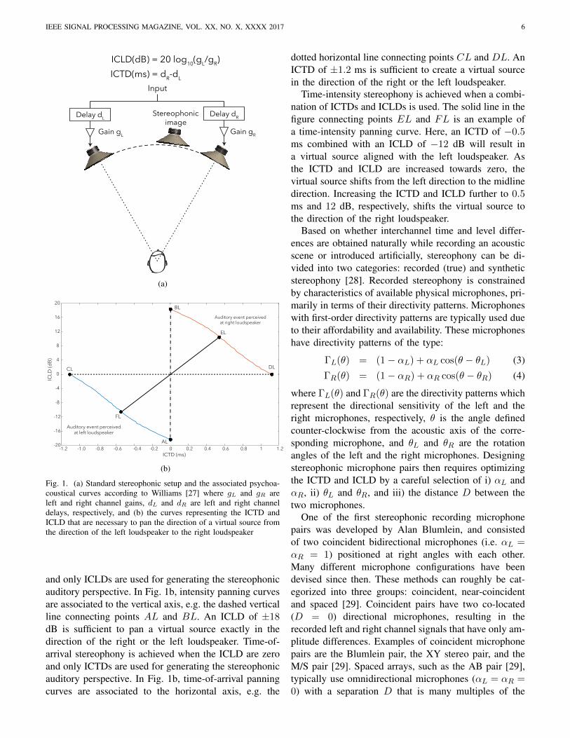
Two-channel stereophony is an alternative spatial au-dio technology which requires the minimal number ofchannels to produce the impression of spatial sound.In the usual implementation, two-channel stereophonyuses two loudspeakers, at the same distance from thelistener, positioned 30◦ to either side of the front di-rection, to provide a frontal auditory scene within abase angle of 60◦. The ideal listening position, referredto as the sweet spot, thus forms an equilateral trianglewith the loudspeakers. Two-channel stereophony createsthe illusion of a sound source in a given directionwithin the base angle by means of interchannel timedifferences (ICTD) and interchannel level differences(ICLD) of the two channels over which the source signalis presented. Fig. 1a shows the standard stereophonicsetup and illustrated how the gains and delays of eachchannel are linked to ICTD and ICLD.
Although it is intuitively clear that the direction ofthe virtual source is pulled towards the loudspeakerwhich produces the louder and earlier version of thesignal, knowing the precise relationship between theperceived source direction and presented (ICTD, ICLD)pairs requires extensive psychoacoustic measurements.
The first comprehensive study of the relationshipsbetween ICTD and ICLD, referred to as stereophonicpanning laws, was conducted by Franssen [26]. Anotherstudy by Williams [27] combined earlier studies on ICTDand ICLD, and the panning curves presented in thatstudy are now known as Williams’ curves. Williams’psychoacoustic curves are illustrated in Fig. 1b, whichshows curves of (ICTD, ICLD) pairs that create a virtualsource in the direction of the left loudspeaker (the bluecurve) and the right loudspeaker (the orange curve).Pairs of (ICTD, ICLD) that are below or above the twocurves are also localized at the left and right loudspeaker,respectively. Virtual sources in directions between theloudspeakers are then created by means of (ICTD, ICLD)pairs which evolve along a line that connects two pointson the psychoacoustic curves.
Note that there are many different (ICTD, ICLD) pairsthat can create a virtual source in the same direction.Intensity stereophony is achieved when the ICTD is zero
IEEE SIGNAL PROCESSING MAGAZINE, VOL. XX, NO. X, XXXX 2017 6
Stereophonicimage
Delay dL
Gain gL
Delay dR
Gain gR
Input
ICLD(dB) = 20 log10(gL/gR)ICTD(ms) = dR-dL
(a)
ICTD (ms)0 0.2 0.4 0.6 0.8 1 1.2
ICLD
(dB)
0
4
8
12
16
20
-1.2 -1.0 -0.8 -0.6 -0.4 -0.2-20
-16
-12
-8
-4
Auditory event perceivedat right loudspeaker
Auditory event perceivedat left loudspeaker
DLCL
EL
BL
FL
AL
(b)
Fig. 1. (a) Standard stereophonic setup and the associated psychoa-coustical curves according to Williams [27] where gL and gR areleft and right channel gains, dL and dR are left and right channeldelays, respectively, and (b) the curves representing the ICTD andICLD that are necessary to pan the direction of a virtual source fromthe direction of the left loudspeaker to the right loudspeaker
and only ICLDs are used for generating the stereophonicauditory perspective. In Fig. 1b, intensity panning curvesare associated to the vertical axis, e.g. the dashed verticalline connecting points AL and BL. An ICLD of ±18dB is sufficient to pan a virtual source exactly in thedirection of the right or the left loudspeaker. Time-of-arrival stereophony is achieved when the ICLD are zeroand only ICTDs are used for generating the stereophonicauditory perspective. In Fig. 1b, time-of-arrival panningcurves are associated to the horizontal axis, e.g. the
dotted horizontal line connecting points CL and DL. AnICTD of ±1.2 ms is sufficient to create a virtual sourcein the direction of the right or the left loudspeaker.
Time-intensity stereophony is achieved when a combi-nation of ICTDs and ICLDs is used. The solid line in thefigure connecting points EL and FL is an example ofa time-intensity panning curve. Here, an ICTD of −0.5ms combined with an ICLD of −12 dB will result ina virtual source aligned with the left loudspeaker. Asthe ICTD and ICLD are increased towards zero, thevirtual source shifts from the left direction to the midlinedirection. Increasing the ICTD and ICLD further to 0.5ms and 12 dB, respectively, shifts the virtual source tothe direction of the right loudspeaker.
Based on whether interchannel time and level differ-ences are obtained naturally while recording an acousticscene or introduced artificially, stereophony can be di-vided into two categories: recorded (true) and syntheticstereophony [28]. Recorded stereophony is constrainedby characteristics of available physical microphones, pri-marily in terms of their directivity patterns. Microphoneswith first-order directivity patterns are typically used dueto their affordability and availability. These microphoneshave directivity patterns of the type:
ΓL(θ) = (1− αL) + αL cos(θ − θL) (3)
ΓR(θ) = (1− αR) + αR cos(θ − θR) (4)
where ΓL(θ) and ΓR(θ) are the directivity patterns whichrepresent the directional sensitivity of the left and theright microphones, respectively, θ is the angle definedcounter-clockwise from the acoustic axis of the corre-sponding microphone, and θL and θR are the rotationangles of the left and the right microphones. Designingstereophonic microphone pairs then requires optimizingthe ICTD and ICLD by a careful selection of i) αL andαR, ii) θL and θR, and iii) the distance D between thetwo microphones.
One of the first stereophonic recording microphonepairs was developed by Alan Blumlein, and consistedof two coincident bidirectional microphones (i.e. αL =αR = 1) positioned at right angles with each other.Many different microphone configurations have beendevised since then. These methods can roughly be cat-egorized into three groups: coincident, near-coincidentand spaced [29]. Coincident pairs have two co-located(D = 0) directional microphones, resulting in therecorded left and right channel signals that have only am-plitude differences. Examples of coincident microphonepairs are the Blumlein pair, the XY stereo pair, and theM/S pair [29]. Spaced arrays, such as the AB pair [29],typically use omnidirectional microphones (αL = αR =0) with a separation D that is many multiples of the
IEEE SIGNAL PROCESSING MAGAZINE, VOL. XX, NO. X, XXXX 2017 7
desired wavelength. This makes the ICTD the main cueused to pan the sound source. Near-coincident recordingtechniques on the other hand use directional microphonesseparated by a small distance comparable to the size ofa human head and record both ICTD and ICLD. Twonotable examples are the Nederlandse Omroep Stichting(NOS) and Office de Radiodiffusion Television Francaise(ORFT) pairs which both use cardioid (αL = αR = 0.5)microphones and have separations of DORTF = 17 cmand DNOS = 30 cm, respectively [29].
Synthetic stereophony has been predominantly basedon intensity panning, since it is considered to provide themost stable virtual sound imaging. Indeed, the inclusionof ICTDs is sometimes considered to yield audible arti-facts, such as tonal coloration due to comb filter effects.Another often cited reason to avoid using ICTDs is thedifficulty of controlling the direction of a virtual sourceby means of time delays. This view has been recentlychallenged [30], as it will be discussed in Section IV-C.
The general form of an intensity panning law relatesthe gains gL and gR of the left and right loudspeakers,respectively, to a function of the source direction θs andthe stereophonic base angle θB , between the loudspeak-ers. More specifically, a panning law has the form:
gL(θs)− gR(θs)
gL(θs) + gR(θs)=f(θs)
f(θB). (5)
The total power can be maintained via the constant powerconstraint gL(θs)
2 + gR(θs)2 = 1. Two commonly used
functions are f(θ) = sin(θ) and f(θ) = tan(θ) whichgive rise to so called the sine panning law and tangentpanning law, respectively.
The tangent panning law has been derived basedon perceptual considerations independent from knownpsychoacoustic curves [31]. In the context of Williams’psychoacoustic curves (see Fig, 1b), the tangent panninglaw operates along the vertical axis, i.e. zero ICTDs, andconnects two points with ±∞ level differences. Thus, asopposed to panning laws described by Williams’ curves,which specify minimal level differences needed to createvirtual sources in loudspeaker directions, the tangent lawachieves the same affect by employing maximal leveldifferences.
C. Multichannel Stereophony
An early work by Steinberg and Snow [32] in 1934suggested that better auditory perspective is possible if atleast three independent microphones are used to capturea frontal sound field and these signals are played backvia three loudspeakers. Due to the hardware requirementsand technical difficulties in the integration of a three-channel system in the radio broadcast, however, this
finding has been obscured by the success and widespreadadoption of two-channel stereophony.
The advent of quadrophony and cinematic soundspurred interest in multichannel systems. Traditionallythere are two different types of multichannel audioformats: discrete and matrix [33] [34]. In discrete mul-tichannel audio, there is one-to-one correspondence be-tween channels and speakers. The storage and transmis-sion of multichannel audio are all made using the samenumber of channels. In matrix multichannel, the originalchannels are encoded to a smaller number of (e.g. two)channels for transmission/storage over common chan-nels/media and then decoded back to the original channelmultiplicity prior to playback. This requires appendingauxiliary information to the encoded audio to be used atthe decoding stage. More recently, object-based formatshave appeared where content and context are encodedseparately.
Surround sound is the more commonly known namefor multichannel stereophony. There exist several repro-duction setups such as 5.1, 7.1, 10.2, and 22.2, whichuse 5, 7, 10, and 22 main channels, respectively and1 or 2 low-frequency channels, as described in an ITUreport (ITU-R BS.2159-4). There are also commercial,object-based formats such as Dolby ATMOS6, DTS-X7
and Auro-3D8 which are very flexible and are likely todominate the cinematic sound industry in the foreseeablefuture considering the new ISO/IEC standards such asMPEG-D and MPEG-H.
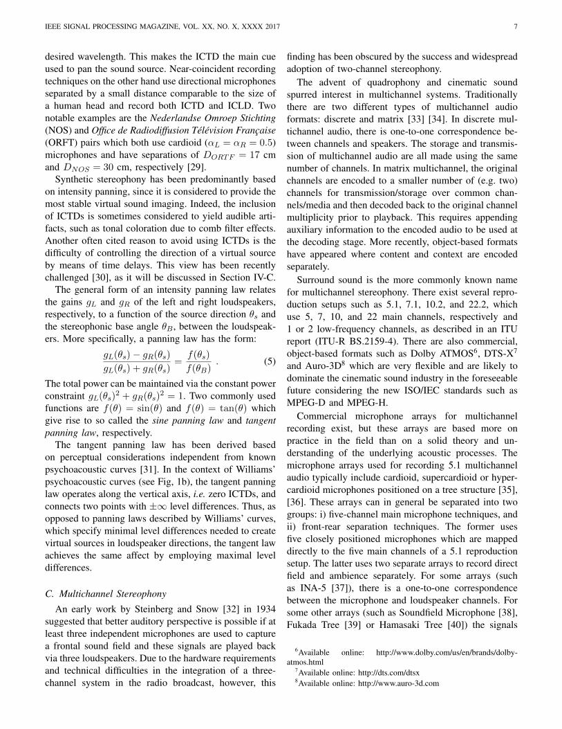
Commercial microphone arrays for multichannelrecording exist, but these arrays are based more onpractice in the field than on a solid theory and un-derstanding of the underlying acoustic processes. Themicrophone arrays used for recording 5.1 multichannelaudio typically include cardioid, supercardioid or hyper-cardioid microphones positioned on a tree structure [35],[36]. These arrays can in general be separated into twogroups: i) five-channel main microphone techniques, andii) front-rear separation techniques. The former usesfive closely positioned microphones which are mappeddirectly to the five main channels of a 5.1 reproductionsetup. The latter uses two separate arrays to record directfield and ambience separately. For some arrays (suchas INA-5 [37]), there is a one-to-one correspondencebetween the microphone and loudspeaker channels. Forsome other arrays (such as Soundfield Microphone [38],Fukada Tree [39] or Hamasaki Tree [40]) the signals
6Available online: http://www.dolby.com/us/en/brands/dolby-atmos.html
7Available online: http://dts.com/dtsx8Available online: http://www.auro-3d.com

IEEE SIGNAL PROCESSING MAGAZINE, VOL. XX, NO. X, XXXX 2017 8
obtained from individual microphone channels need tobe mixed.
Some well-known multichannel arrays used forrecording multichannel audio are shown in Fig. 2. It maybe observed that a variety of microphone arrangementsexist that try to address the common objective of obtain-ing an authentic auditory perspective and a high levelof envelopment and immersion using existing first-ordermicrophone directivity patterns.
The microphone arrays for recording 10.2 multichan-nel stereophony are still rather experimental (see ITU-R BS.2159-4 report). Similarly, recording for a 22.2reproduction system will depend strongly on the venueand context. In fact, multichannel stereophonic systemswith higher channel counts, by virtue of the degrees ofdesign freedom they provide, allow for more flexibility,but also make it more difficult to design recording setupswith strict perceptual rationale.
Recommended reproduction setups for multichannelsystems are either standardized (e.g. ITU-R BS.775-1) or in the process of standardization by differentstandardization bodies [41]. These setups mainly relyon the frontal channels for the presentation of audiocontent which accompany visual content (usually filmsor games). The left and right front channels typicallycorrespond exactly to the two-channel stereophonic setupfor cross- and backwards compatibility. The differencein these setups is mainly about how ambience is playedback. Some of the standards like ITU-R BS.1116.1and ITU-R BS.1534.1 define formal procedures for thesubjective evaluation of these systems.
IV. PERCEPTUALLY-MOTIVATEDMULTICHANNEL RECORDING AND
REPRODUCTION
There has been some recent work in the directionof developing systematic frameworks for the design ofmultichannel stereo systems, most notably Vector-baseAmplitude Panning (VBAP), Directional Audio Coding(DirAC), and Perceptual Sound Field Reconstruction(PSR). We review them in this section.
A. Vector-base Amplitude Panning (VBAP)
It was shown as early as 1973 that tangent panningprovides a stereophonic image that is more robust to headrotations than sine panning for the standard stereophonicloudspeaker setup [31]. Pulkki showed that tangent pan-ning can be expressed using an equivalent, vector-basedformulation in the horizontal plane and also proposeda three dimensional extension to two-channel intensitypanning which allows rendering elevated virtual sources
over flexible loudspeaker rigs [42]. This method is calledvector-base amplitude panning (VBAP).
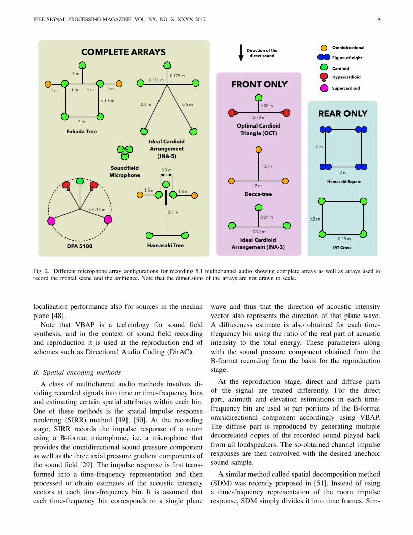
Originally, VBAP was designed for a loudspeakerarray with elements placed on the vertices of a geodesicdome that are situated at the acoustic far field of thelistener. Fig. 3 shows a section of such a sphere withthree loudspeakers with a listener positioned at the centerof the array. The directions of the three loudspeakers areindicated as v1, v2, and v3, and the corresponding gainsas g1, g2, and g3. A virtual source in a direction vsbetween the loudspeakers can be generated by selectingthe gains that satisfy vs = Vg where V is a matrixwhose columns are the directions of the loudspeakers andg = [g1 g2 g3]
T . In addition, the calculated loudspeakergains are normalised in order to keep the total powerconstant.
On the full geodesic sphere, active regions are selectedbased on the closest three points on the grid and onlythose loudspeakers are used for source rendition. Thisis in contrast with physically-based approaches suchas Ambisonics where even for a single source from asingle direction, all loudspeakers are potentially active.A major assumption behind VBAP in three dimensionsis that summing localization would occur not only withtwo, but also with three sources. This assumption wassubjectively tested for different setups and virtual sourcedirections and it was shown to result in a good subjectivelocalization accuracy for elevated virtual sources [43],[44].
An issue resulting from utilization of intensity panningin VBAP is the nonuniformity of the spatial spread of thepanned source. More specifically, sources panned closerto the actual loudspeakers in the reproduction rig havea smaller spatial spread, while virtual sources pannedto directions between loudspeakers have a larger spatialspread. The main cause of this issue is the usage ofa single loudspeaker when the virtual source directioncoincides with the direction of that loudspeaker.
This issue was addressed by panning the virtual sourceto multiple directions by using three loudspeakers (in-stead of two) for all source directions in the horizontalplane or four loudspeakers (instead of three) in the3D case. This approach was called as multiple-speakeramplitude panning (MDAP) [45]. In a study comparingVBAP with MDAP it was shown that both VBAP andMDAP provide good subjective localization accuracywith MDAP being more accurate than VBAP [46]. Inanother, more recent evaluation carried out within thecontext of the MPEG-H standard, VBAP resulted invery good subjective localization accuracy including notonly the source azimuth but also its distance [47]. Inyet another study, VBAP was shown to provide good
IEEE SIGNAL PROCESSING MAGAZINE, VOL. XX, NO. X, XXXX 2017 9
2 m
2 m
Hamasaki Square
0.2 m
0.25 m
IRT Cross
SoundfieldMicrophone
DPA 5100
Direction of thedirect sound
Optimal CardioidTriangle (OCT)
0.70 m
0.08 m
Decca-tree2 m
1.5 m
Ideal CardioidArrangement (INA-3)
1 m 1 m 1 m
1 m
1 m
2 m
< 1.8 m
Fukada Tree
0.92 m
0.27 m
Ideal CardioidArrangement
(INA-5)
0.175 m0.175 m
0.6 m0.6 m
Omnidirectional
Figure-of-eight
Cardioid
Supercardioid
Hypercardioid
< 0.15 m 2-3 m
1.5 m
0.3 m
1.5 m
Hamasaki Tree
COMPLETE ARRAYS
FRONT ONLY
REAR ONLY
Fig. 2. Different microphone array configurations for recording 5.1 multichannel audio showing complete arrays as well as arrays used torecord the frontal scene and the ambience. Note that the dimensions of the arrays are not drawn to scale.
localization performance also for sources in the medianplane [48].
Note that VBAP is a technology for sound fieldsynthesis, and in the context of sound field recordingand reproduction it is used at the reproduction end ofschemes such as Directional Audio Coding (DirAC).
B. Spatial encoding methods
A class of multichannel audio methods involves di-viding recorded signals into time or time-frequency binsand estimating certain spatial attributes within each bin.One of these methods is the spatial impulse responserendering (SIRR) method [49], [50]. At the recordingstage, SIRR records the impulse response of a roomusing a B-format microphone, i.e. a microphone thatprovides the omnidirectional sound pressure componentas well as the three axial pressure gradient components ofthe sound field [29]. The impulse response is first trans-formed into a time-frequency representation and thenprocessed to obtain estimates of the acoustic intensityvectors at each time-frequency bin. It is assumed thateach time-frequency bin corresponds to a single plane
wave and thus that the direction of acoustic intensityvector also represents the direction of that plane wave.A diffuseness estimate is also obtained for each time-frequency bin using the ratio of the real part of acousticintensity to the total energy. These parameters alongwith the sound pressure component obtained from theB-format recording form the basis for the reproductionstage.
At the reproduction stage, direct and diffuse partsof the signal are treated differently. For the directpart, azimuth and elevation estimations in each time-frequency bin are used to pan portions of the B-formatomnidirectional component accordingly using VBAP.The diffuse part is reproduced by generating multipledecorrelated copies of the recorded sound played backfrom all loudspeakers. The so-obtained channel impulseresponses are then convolved with the desired anechoicsound sample.
A similar method called spatial decomposition method(SDM) was recently proposed in [51]. Instead of usinga time-frequency representation of the room impulseresponse, SDM simply divides it into time frames. Sim-
IEEE SIGNAL PROCESSING MAGAZINE, VOL. XX, NO. X, XXXX 2017 10
Fig. 3. Arrangement of three loudspeakers and a phantom imagepanned using VBAP. The vectors used in the formulation of VBAPare also shown.
ilarly to SIRR, SDM assumes that within each timeframe there is at most a single acoustic event (e.g. areflection from the room walls), the direction of which iscalculated using available direction-of-arrival estimationalgorithms. Using this estimate, each time frame of theimpulse response is panned between the loudspeakersusing VBAP. The loudspeaker signals are then convolvedwith the desired anechoic sound sample.
Notice that, as opposed to SIRR, SDM does notexplicitly differentiate direct and diffuse components.However, the later part of the room impulse response isstill rendered as diffuse. This is due to the fact that, astime progresses, a progressively larger number of echoesappear within each time frame, and, as a consequence,the direction-of-arrival algorithm tends to provide ran-dom estimates. In a formal listening experiment usingsynthesised room impulse responses, SDM was shownto outperform SIRR [51].
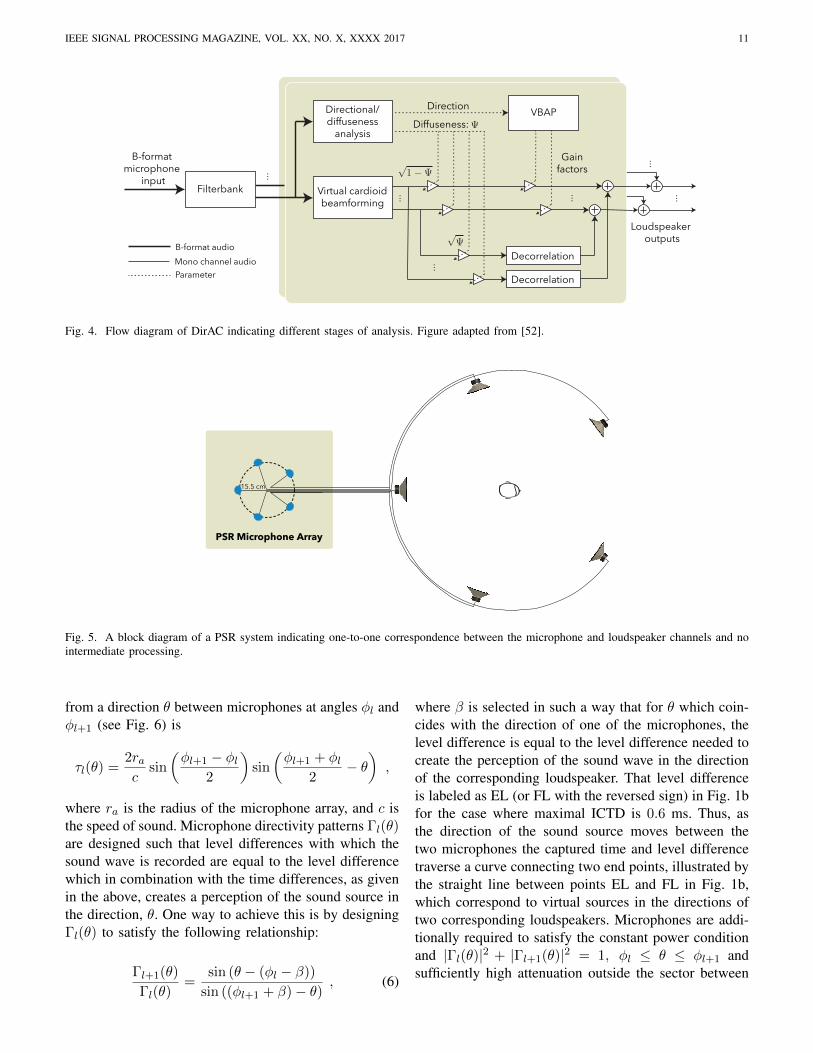
SIRR and SDM are not designed for continuoussignals but for spatial room impulse responses, which arethen convolved with an anechoic signal. In other words,they cannot be used for actual recordings of dynamicsound scenes. Directional Audio Coding (DirAC) is aflexible spatial audio system for recording, coding, com-pression, transmission and reproduction based on SIRRthat overcomes this limitation [52]. Similarly to SIRR,DirAC starts with an energy analysis of the recordedsound, to assign a direction and a diffuseness level to
each instant of the output channels of a filter bankthat approximates the equivalent rectangular bandwidth(ERB) scale. The direction predictions are then smoothedto imitate the temporal resolution of the auditory system.At the reproduction stage, these components are pannedusing VBAP. Fig. 4 shows the recording, processing andreproduction stages of DirAC.
DirAC was evaluated and compared with Ambisonics(with different decoders) for reproduction quality usinglistening tests similar to MUSHRA [53]. The evaluationincluded different loudspeaker rigs (with 4, 5, 8, 12,and 16 loudspeakers), different audio material (music,speech, singing voice, percussion), different simulatedreverberation characteristics, and different listener posi-tions. It was found that DirAC provides an excellent re-production quality (better than 80 on average over a max-imum rating of 100) for the central listening position,and acceptable reproduction quality (better than 60 onaverage over a maximum rating of 100) for the off-centerpositions. Ambisonics reproductions obtained using bothdecoders were rated consistently below DirAC. Theseresults provide an instructive example of a perceptually-motivated reproduction method achieving better subjec-tive performance than a physically-motivated approach.
C. Perceptual Sound Field Reconstruction
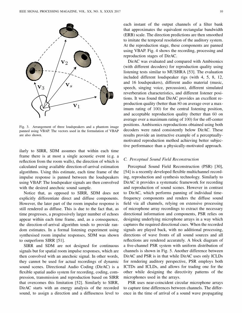
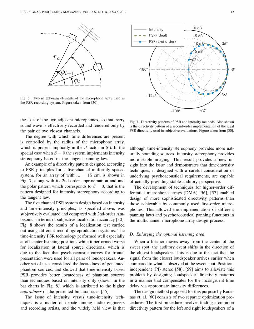
Perceptual Sound Field Reconstruction (PSR) [30],[54] is a recently developed flexible multichannel record-ing, reproduction and synthesis technology. Similarly toDirAC it provides a systematic framework for recordingand reproduction of sound scenes. However in contrastto DirAC, which performs panning of individual time-frequency components and renders the diffuse soundfield via all channels, relying on extensive processingof microphone array recordings to extract the necessarydirectional information and components, PSR relies ondesigning underlying microphone arrays in a way whichcaptures the required directional cues. When the recordedsignals are played back, with no additional processing,directions of wave fronts of all sound sources and allreflections are rendered accurately. A block diagram ofa five-channel PSR system with uniform distribution ofchannels is shown in Fig. 5. Another difference betweenDirAC and PSR is in that while DirAC uses only ICLDsfor rendering auditory perspective, PSR employs bothICTDs and ICLDs, and allows for trading one for theother while designing the directivity patterns of themicrophones used in the arrays.
PSR uses near-coincident circular microphone arraysto capture time differences between channels. The differ-ence in the time of arrival of a sound wave propagating
IEEE SIGNAL PROCESSING MAGAZINE, VOL. XX, NO. X, XXXX 2017 11
B-formatmicrophone
inputFilterbank
Directional/diffuseness
analysis
VBAP
Virtual cardioidbeamforming
Decorrelation
Decorrelation
...
...
...
...
Loudspeaker outputs
Gainfactors
...
...
DirectionDiffuseness:
B-format audioMono channel audioParameter
Fig. 4. Flow diagram of DirAC indicating different stages of analysis. Figure adapted from [52].
PSR Microphone Array
15.5 cm
Fig. 5. A block diagram of a PSR system indicating one-to-one correspondence between the microphone and loudspeaker channels and nointermediate processing.
from a direction θ between microphones at angles φl andφl+1 (see Fig. 6) is
τl(θ) =2rac
sin
(φl+1 − φl
2
)sin
(φl+1 + φl
2− θ
),
where ra is the radius of the microphone array, and c isthe speed of sound. Microphone directivity patterns Γl(θ)are designed such that level differences with which thesound wave is recorded are equal to the level differencewhich in combination with the time differences, as givenin the above, creates a perception of the sound source inthe direction, θ. One way to achieve this is by designingΓl(θ) to satisfy the following relationship:
Γl+1(θ)
Γl(θ)=
sin (θ − (φl − β))
sin ((φl+1 + β)− θ), (6)
where β is selected in such a way that for θ which coin-cides with the direction of one of the microphones, thelevel difference is equal to the level difference needed tocreate the perception of the sound wave in the directionof the corresponding loudspeaker. That level differenceis labeled as EL (or FL with the reversed sign) in Fig. 1bfor the case where maximal ICTD is 0.6 ms. Thus, asthe direction of the sound source moves between thetwo microphones the captured time and level differencetraverse a curve connecting two end points, illustrated bythe straight line between points EL and FL in Fig. 1b,which correspond to virtual sources in the directions oftwo corresponding loudspeakers. Microphones are addi-tionally required to satisfy the constant power conditionand |Γl(θ)|2 + |Γl+1(θ)|2 = 1, φl ≤ θ ≤ φl+1 andsufficiently high attenuation outside the sector between
IEEE SIGNAL PROCESSING MAGAZINE, VOL. XX, NO. X, XXXX 2017 12
Fig. 6. Two neighboring elements of the microphone array used inthe PSR recording system. Figure taken from [30].
the axes of the two adjacent microphones, so that everysound wave is effectively recorded and rendered only bythe pair of two closest channels.
The degree with which time differences are presentis controlled by the radius of the microphone array,which is present implicitly in the β factor in (6). In thespecial case when β = 0 the system implements intensitystereophony based on the tangent panning law.
An example of a directivity pattern designed accordingto PSR principles for a five-channel uniformly spacedsystem, for an array of with ra = 15 cm, is shown inFig. 7, along with its 2nd-order approximation and andthe polar pattern which corresponds to β = 0, that is thepattern designed for intensity stereophony according tothe tangent law.
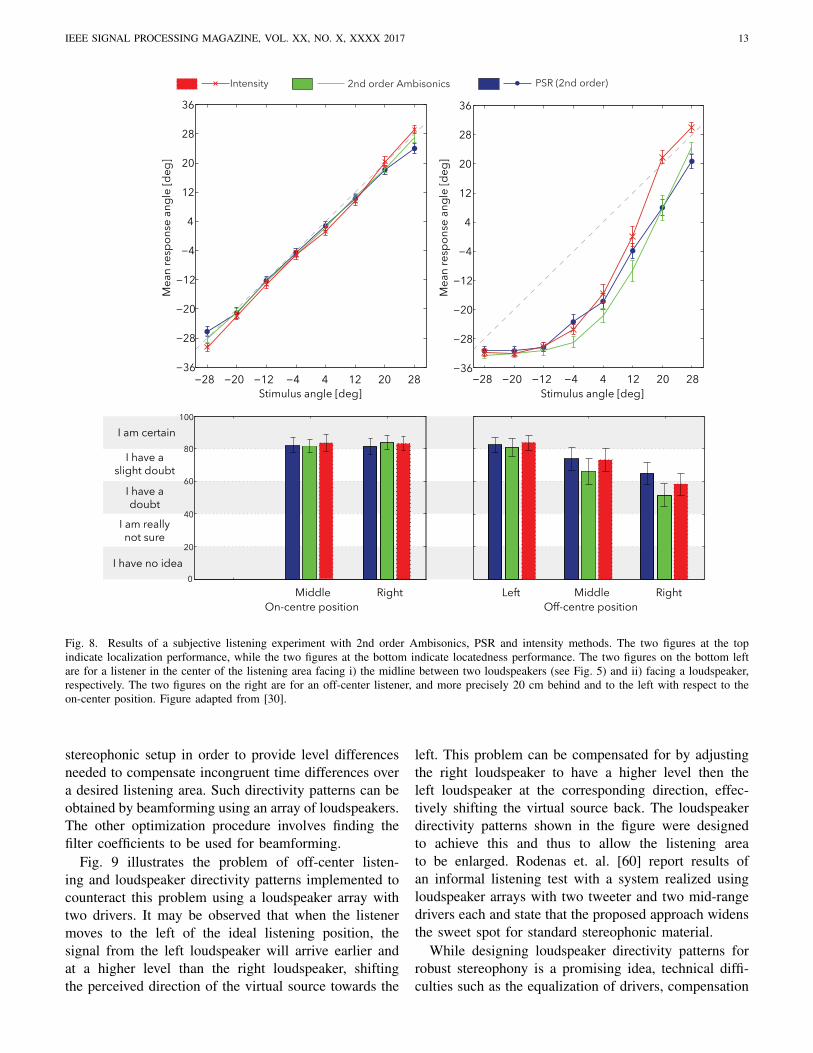
The five channel PSR system design based on intensityand time-intensity principles, as specified above, wassubjectively evaluated and compared with 2nd-order Am-bisonics in terms of subjective localization accuracy [30].Fig. 8 shows the results of a localization test carriedout using different recording/reproduction systems. Thetime-intensity PSR technology performed well especiallyat off-center listening positions while it performed worsefor localization at lateral source directions, which isdue to the fact that psychoacoustic curves for frontalpresentation were used for all pairs of loudspeakers. An-other set of tests considered the locatedness of generatedphantom sources, and showed that time-intensity basedPSR provides better locatedness of phantom sourcesthan techniques based on intensity only (shown in thebar charts in Fig. 8), which is attributed to the highernaturalness of the presented binaural cues [55].
The issue of intensity versus time-intensity tech-niques is a matter of debate among audio engineersand recording artists, and the widely held view is that
0 dB
36°
-36°
-72°-108°
-144°
-180° -0°
20 dB
15 dB
10 dB
5 dBIntensityPSR (ideal)PSR (2nd order)
Fig. 7. Directivity patterns of PSR and intensity methods. Also shownis the directivity pattern of a second-order implementation of the idealPSR directivity used in subjective evaluations. Figure taken from [30].
although time-intensity stereophony provides more nat-urally sounding sources, intensity stereophony providesmore stable imaging. This result provides a new in-sight into the issue and demonstrates that time-intensitytechniques, if designed with a careful consideration ofunderlying psychoacoustical requirements, are capableof actually providing stable auditory perspective.
The development of techniques for higher-order dif-ferential microphone arrays (DMA) [56], [57] enableddesign of more sophisticated directivity patterns thanthose achievable by commonly used first-order micro-phones. This allowed the implementation of differentpanning laws and psychoacoustical panning functions inthe multichannel microphone array design process.
D. Enlarging the optimal listening area
When a listener moves away from the center of thesweet spot, the auditory event shifts in the direction ofthe closest loudspeaker. This is due to the fact that thesignal from the closest loudspeaker arrives earlier whencompared to what is observed at the sweet spot. Position-independent (PI) stereo [58], [59] aims to alleviate thisproblem by designing loudspeaker directivity patternsin a manner that compensates for the incongruent timedelay via appropriate intensity differences.
The design method proposed for this purpose by Rode-nas et. al. [60] consists of two separate optimization pro-cedures. The first procedure involves finding a commondirectivity pattern for the left and right loudspeakers of a
IEEE SIGNAL PROCESSING MAGAZINE, VOL. XX, NO. X, XXXX 2017 13
−28 −20 −12 −4 4 12 20 28
Stimulus angle [deg]
Me
an
re
sp
on
se
an
gle
[d
eg
]
−36
−28
−20
−12
−4
4
12
20
28
36
−28 −20 −12 −4 4 12 20 28Stimulus angle [deg]
Mea
n re
spon
se an
gle
[deg
]
−36
−28
−20
−12
−4
4
12
20
28
36
PSR (2nd order)Intensity 2nd order Ambisonics
0
20
40
60
80
100I am certain
I have a
slight doubt
I have a
doubt
I am really
not sure
I have no idea
Middle
On-centre position
Right Middle
Off-centre position
RightLeft
Fig. 8. Results of a subjective listening experiment with 2nd order Ambisonics, PSR and intensity methods. The two figures at the topindicate localization performance, while the two figures at the bottom indicate locatedness performance. The two figures on the bottom leftare for a listener in the center of the listening area facing i) the midline between two loudspeakers (see Fig. 5) and ii) facing a loudspeaker,respectively. The two figures on the right are for an off-center listener, and more precisely 20 cm behind and to the left with respect to theon-center position. Figure adapted from [30].
stereophonic setup in order to provide level differencesneeded to compensate incongruent time differences overa desired listening area. Such directivity patterns can beobtained by beamforming using an array of loudspeakers.The other optimization procedure involves finding thefilter coefficients to be used for beamforming.
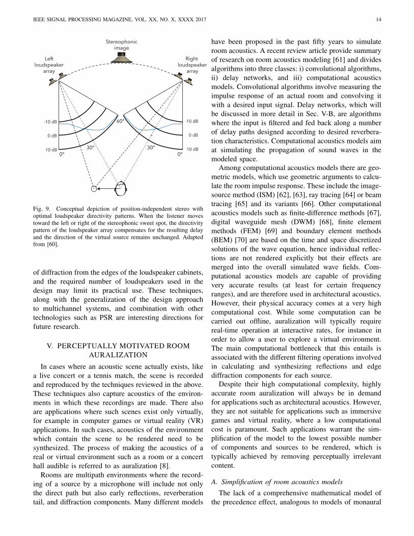
Fig. 9 illustrates the problem of off-center listen-ing and loudspeaker directivity patterns implemented tocounteract this problem using a loudspeaker array withtwo drivers. It may be observed that when the listenermoves to the left of the ideal listening position, thesignal from the left loudspeaker will arrive earlier andat a higher level than the right loudspeaker, shiftingthe perceived direction of the virtual source towards the
left. This problem can be compensated for by adjustingthe right loudspeaker to have a higher level then theleft loudspeaker at the corresponding direction, effec-tively shifting the virtual source back. The loudspeakerdirectivity patterns shown in the figure were designedto achieve this and thus to allow the listening areato be enlarged. Rodenas et. al. [60] report results ofan informal listening test with a system realized usingloudspeaker arrays with two tweeter and two mid-rangedrivers each and state that the proposed approach widensthe sweet spot for standard stereophonic material.
While designing loudspeaker directivity patterns forrobust stereophony is a promising idea, technical diffi-culties such as the equalization of drivers, compensation
IEEE SIGNAL PROCESSING MAGAZINE, VOL. XX, NO. X, XXXX 2017 14
Right loudspeaker
array
Leftloudspeaker
array
Stereophonicimage
0°
0 dB
-10 dB
10 dB
0 dB
-10 dB
10 dB
°
30°
60°
0°30°
Fig. 9. Conceptual depiction of position-independent stereo withoptimal loudspeaker directivity patterns. When the listener movestoward the left or right of the stereophonic sweet spot, the directivitypattern of the loudspeaker array compensates for the resulting delayand the direction of the virtual source remains unchanged. Adaptedfrom [60].
of diffraction from the edges of the loudspeaker cabinets,and the required number of loudspeakers used in thedesign may limit its practical use. These techniques,along with the generalization of the design approachto multichannel systems, and combination with othertechnologies such as PSR are interesting directions forfuture research.
V. PERCEPTUALLY MOTIVATED ROOMAURALIZATION
In cases where an acoustic scene actually exists, likea live concert or a tennis match, the scene is recordedand reproduced by the techniques reviewed in the above.These techniques also capture acoustics of the environ-ments in which these recordings are made. There alsoare applications where such scenes exist only virtually,for example in computer games or virtual reality (VR)applications. In such cases, acoustics of the environmentwhich contain the scene to be rendered need to besynthesized. The process of making the acoustics of areal or virtual environment such as a room or a concerthall audible is referred to as auralization [8].
Rooms are multipath environments where the record-ing of a source by a microphone will include not onlythe direct path but also early reflections, reverberationtail, and diffraction components. Many different models
have been proposed in the past fifty years to simulateroom acoustics. A recent review article provide summaryof research on room acoustics modeling [61] and dividesalgorithms into three classes: i) convolutional algorithms,ii) delay networks, and iii) computational acousticsmodels. Convolutional algorithms involve measuring theimpulse response of an actual room and convolving itwith a desired input signal. Delay networks, which willbe discussed in more detail in Sec. V-B, are algorithmswhere the input is filtered and fed back along a numberof delay paths designed according to desired reverbera-tion characteristics. Computational acoustics models aimat simulating the propagation of sound waves in themodeled space.
Among computational acoustics models there are geo-metric models, which use geometric arguments to calcu-late the room impulse response. These include the image-source method (ISM) [62], [63], ray tracing [64] or beamtracing [65] and its variants [66]. Other computationalacoustics models such as finite-difference methods [67],digital waveguide mesh (DWM) [68], finite elementmethods (FEM) [69] and boundary element methods(BEM) [70] are based on the time and space discretizedsolutions of the wave equation, hence individual reflec-tions are not rendered explicitly but their effects aremerged into the overall simulated wave fields. Com-putational acoustics models are capable of providingvery accurate results (at least for certain frequencyranges), and are therefore used in architectural acoustics.However, their physical accuracy comes at a very highcomputational cost. While some computation can becarried out offline, auralization will typically requirereal-time operation at interactive rates, for instance inorder to allow a user to explore a virtual environment.The main computational bottleneck that this entails isassociated with the different filtering operations involvedin calculating and synthesizing reflections and edgediffraction components for each source.
Despite their high computational complexity, highlyaccurate room auralization will always be in demandfor applications such as architectural acoustics. However,they are not suitable for applications such as immersivegames and virtual reality, where a low computationalcost is paramount. Such applications warrant the sim-plification of the model to the lowest possible numberof components and sources to be rendered, which istypically achieved by removing perceptually irrelevantcontent.
A. Simplification of room acoustics models
The lack of a comprehensive mathematical model ofthe precedence effect, analogous to models of monaural

IEEE SIGNAL PROCESSING MAGAZINE, VOL. XX, NO. X, XXXX 2017 15
masking, has made it difficult for a long time to predictwhether an individual reflection would be audible in thepresence of the direct sound and other reflections. Thisis mainly due to the fact that the audibility of a reflectiondepends on many parameters.
One of the first models that aimed to parameterizethe audibility of reflections, named Reflection MaskedThreshold (RMT), was proposed by Buchholz et al. [71].The RMT is the lowest level at which a reflection willbe audible, and it is a function of the directions of thereflection and of the corresponding direct sound, the timedelay of reflection with respect to the direct sound, thelevel of the direct sound, the difference of the frequencyspectra between the direct sound and the reflection, theeffect of other reflections and reverberation, and thesignal content. RMT can be used for simplifying roomacoustic models via culling inaudible reflections.
A simpler decision rule for culling inaudible earlyreflections was proposed by Begault et al. [72]–[74]based on the relative level of the reflection. In theabsence of reverberation, the audibility threshold of areflection is 21 dB below the level of direct sound fora delay of 3 ms. The presence of diffuse reverberationhas the effect of increasing this threshold by 11 dB.This threshold is also known to decrease with the anglebetween the direct sound and the early reflection.
Properties of binaural hearing, such as the prece-dence effect, may also make some reflections inaudible.The exclusion of those reflections from audio renderingpipeline can further reduce the associated computationalcost. To that end, a model of the precedence effectwas proposed in [75] according to which perceiveddirections of acoustic events are modeled as normallydistributed variables. If the direct path and a reflectionare present, then the distribution of the perceived di-rection is a mixture of two Gaussians. The audibilityof the reflection was then shown to be related to thenumber of modes in the mixture: if the mixture isunimodal the reflection is masked and if it is bimodal itis audible. The derivation of the model parameters wasmade via subjective localization experiments. This modelwas applied for the culling of reflections in binauralroom auralization [76]. More specifically, the imagesource method (ISM) was used to obtain a number ofsecondary sources and these were clustered accordingto their distance from the listener position and theirazimuth angle. A single reflection masker was obtainedfor each cluster using the precedence effect model andthe rest of the secondary sources in the same cluster areexcluded from the rendering pipeline, thereby reducingthe computational cost. Subjective evaluations were car-ried out using different audio material, different room
geometries and different listening positions to comparethe room auralizations using full room response, level-based reflection selection, and perceptually-motivatedselection based on the precedence effect model. Theseexperiments showed that reflection culling based on theprecedence effect is capable of reducing the numberof early reflections by over 60%, without any signifi-cant degradation on subjective localization, spaciousness,presence and envelopment experiences.
Another approach to perceptually-motivated simpli-fication of auralization based on absolute threshold ofhearing was recently proposed [77]. According to thismodel, the duration of ray tracing for calculating theroom impulse responses for a given source depends on atemporal cutoff point determined by the last audible ray.It was shown that this approach resulted in noticeableimprovements in computation time of impulse responseswithout significantly degrading the auditory experience.
B. Perceptually-motivated artificial reverberation
Room impulse responses can be divided in two parts–early reflections, where reflections are separated in timeand have strong directional characteristics, and the re-verberation tail, where higher-order reflections begin tooverlap in time and the sound field becomes diffuse. Thehuman auditory system is sensitive to the direction of thedirect wave front and the early reflections, while it cannotdiscern the directions of individual reflections within thereverberation tail [78]. Level and directions of lateralearly reflections are related directly to the perception ofthe width of a sound source and the spatial impressionof an enclosure [79].
As the density of reflections increases, the statisticalproperties like reflection density and decay slope becomemore important than the fine temporal structure. In realenclosures, sound energy decays exponentially, and thepoint at which the total energy of the room impulseresponse drops 60 dB below its initial value is calledthe reverberation time [80]. The reverberation time hasa strong influence on how spacious an enclosure is per-ceived [78]. Other quantities that have a strong influenceon the perceived quality of reverberation include, thedensity of the individual reflections in the late rever-beration tail, called the reflection density [80], the timedependent profile of reflection density, called the echodensity profile [81], and the number of damped reso-nant frequencies per Hz, called the mode density [82].The typical objective of perceptually-motivated artificialreverberators is to render accurately the properties ofreverberation described above.
Since the early part and the reverberation tail areperceived differently, a common approach is to model
IEEE SIGNAL PROCESSING MAGAZINE, VOL. XX, NO. X, XXXX 2017 16
Modeling
Auralization
Anechoic Signal
Boundaries of the enclosureand the enclosed planesMaterial propertiesReverberation characteristicsSource directivity patterns
3D geometric modelof the enclosure
HRTF filters
Material
filters
Air
absorption
filters
Listener and source
positions and look
directions
Calculate valid and
visible image sources
and diffraction terms
Direct path,
early
reflections,
and edge
diffraction
components
Artificial
reverberation
Head position
and direction
HRTF filter
interpolation
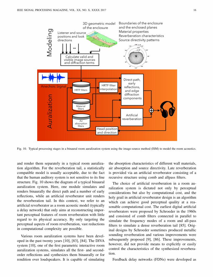
Fig. 10. Typical processing stages in a binaural room auralization system using the image-source method (ISM) to model the room acoustics.
and render them separately in a typical room auraliza-tion algorithm. For the reverberation tail, a statisticallycompatible model is usually acceptable, due to the factthat the human auditory system is not sensitive to its finestructure. Fig. 10 shows the diagram of a typical binauralauralization system. Here, one module simulates andrenders binaurally the direct path and a number of earlyreflections, while an artificial reverberator unit rendersthe reverberation tail. In this context, we refer to anartificial reverberator as a room acoustic model (typicallya delay network) that only aims at reconstructing impor-tant perceptual features of room reverberation with littleregard to its physical accuracy. By only targeting theperceptual aspects of room reverberation, vast reductionsin computational complexity are possible.
Various room auralization systems have been devel-oped in the past twenty years [10], [83], [84]. The DIVAsystem [10], one of the first parametric interactive roomauralization systems, simulates all the first- and second-order reflections and synthesizes them binaurally or forrendition over loudspeakers. It is capable of simulating
the absorption characteristics of different wall materials,air absorption and source directivity. Late reverberationis provided via an artificial reverberator consisting of arecursive structure using comb and allpass filters.
The choice of artificial reverberation in a room au-ralization system is dictated not only by perceptualconsiderations but also by computational cost, and theholy grail in artificial reverberator design is an algorithmwhich can achieve good perceptual quality at a rea-sonable computational cost. The earliest digital artificialreverberators were proposed by Schroeder in the 1960sand consisted of comb filters connected in parallel tosimulate the frequency modes of a room and all-passfilters to simulate a dense reverberation tail [85]. Orig-inal designs by Schroeder sometimes produced metallicsounding reverberation and various improvements weresubsequently proposed [9], [86]. These improvements,however, did not provide means to explicitly or easilycontrol the characteristics of the synthesized reverbera-tion.
Feedback delay networks (FDNs) were developed as
IEEE SIGNAL PROCESSING MAGAZINE, VOL. XX, NO. X, XXXX 2017 17
Delays and
absorption filters
Feedback
matrix
Direct path gain
InputOutput
Output gains
vector
Tone correction
filter
Input gains
vector
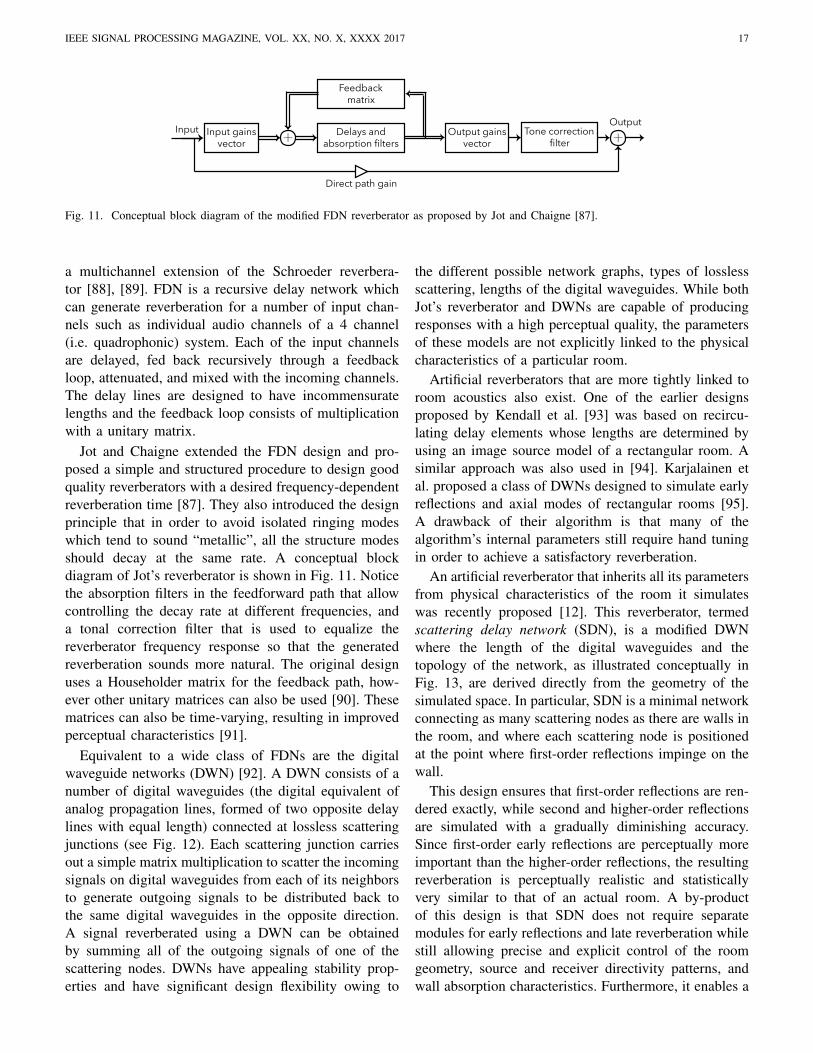
Fig. 11. Conceptual block diagram of the modified FDN reverberator as proposed by Jot and Chaigne [87].
a multichannel extension of the Schroeder reverbera-tor [88], [89]. FDN is a recursive delay network whichcan generate reverberation for a number of input chan-nels such as individual audio channels of a 4 channel(i.e. quadrophonic) system. Each of the input channelsare delayed, fed back recursively through a feedbackloop, attenuated, and mixed with the incoming channels.The delay lines are designed to have incommensuratelengths and the feedback loop consists of multiplicationwith a unitary matrix.
Jot and Chaigne extended the FDN design and pro-posed a simple and structured procedure to design goodquality reverberators with a desired frequency-dependentreverberation time [87]. They also introduced the designprinciple that in order to avoid isolated ringing modeswhich tend to sound “metallic”, all the structure modesshould decay at the same rate. A conceptual blockdiagram of Jot’s reverberator is shown in Fig. 11. Noticethe absorption filters in the feedforward path that allowcontrolling the decay rate at different frequencies, anda tonal correction filter that is used to equalize thereverberator frequency response so that the generatedreverberation sounds more natural. The original designuses a Householder matrix for the feedback path, how-ever other unitary matrices can also be used [90]. Thesematrices can also be time-varying, resulting in improvedperceptual characteristics [91].
Equivalent to a wide class of FDNs are the digitalwaveguide networks (DWN) [92]. A DWN consists of anumber of digital waveguides (the digital equivalent ofanalog propagation lines, formed of two opposite delaylines with equal length) connected at lossless scatteringjunctions (see Fig. 12). Each scattering junction carriesout a simple matrix multiplication to scatter the incomingsignals on digital waveguides from each of its neighborsto generate outgoing signals to be distributed back tothe same digital waveguides in the opposite direction.A signal reverberated using a DWN can be obtainedby summing all of the outgoing signals of one of thescattering nodes. DWNs have appealing stability prop-erties and have significant design flexibility owing to
the different possible network graphs, types of losslessscattering, lengths of the digital waveguides. While bothJot’s reverberator and DWNs are capable of producingresponses with a high perceptual quality, the parametersof these models are not explicitly linked to the physicalcharacteristics of a particular room.
Artificial reverberators that are more tightly linked toroom acoustics also exist. One of the earlier designsproposed by Kendall et al. [93] was based on recircu-lating delay elements whose lengths are determined byusing an image source model of a rectangular room. Asimilar approach was also used in [94]. Karjalainen etal. proposed a class of DWNs designed to simulate earlyreflections and axial modes of rectangular rooms [95].A drawback of their algorithm is that many of thealgorithm’s internal parameters still require hand tuningin order to achieve a satisfactory reverberation.
An artificial reverberator that inherits all its parametersfrom physical characteristics of the room it simulateswas recently proposed [12]. This reverberator, termedscattering delay network (SDN), is a modified DWNwhere the length of the digital waveguides and thetopology of the network, as illustrated conceptually inFig. 13, are derived directly from the geometry of thesimulated space. In particular, SDN is a minimal networkconnecting as many scattering nodes as there are walls inthe room, and where each scattering node is positionedat the point where first-order reflections impinge on thewall.
This design ensures that first-order reflections are ren-dered exactly, while second and higher-order reflectionsare simulated with a gradually diminishing accuracy.Since first-order early reflections are perceptually moreimportant than the higher-order reflections, the resultingreverberation is perceptually realistic and statisticallyvery similar to that of an actual room. A by-productof this design is that SDN does not require separatemodules for early reflections and late reverberation whilestill allowing precise and explicit control of the roomgeometry, source and receiver directivity patterns, andwall absorption characteristics. Furthermore, it enables a
IEEE SIGNAL PROCESSING MAGAZINE, VOL. XX, NO. X, XXXX 2017 18
1
3
S5
S4
2 5
27 ms
57 ms 713 ms
160 m
s
479 ms
10
51
ms
157 ms
37 ms
157 ms
LOSSLESS
DWN
Input
Output
Fs= 44.1 kHz
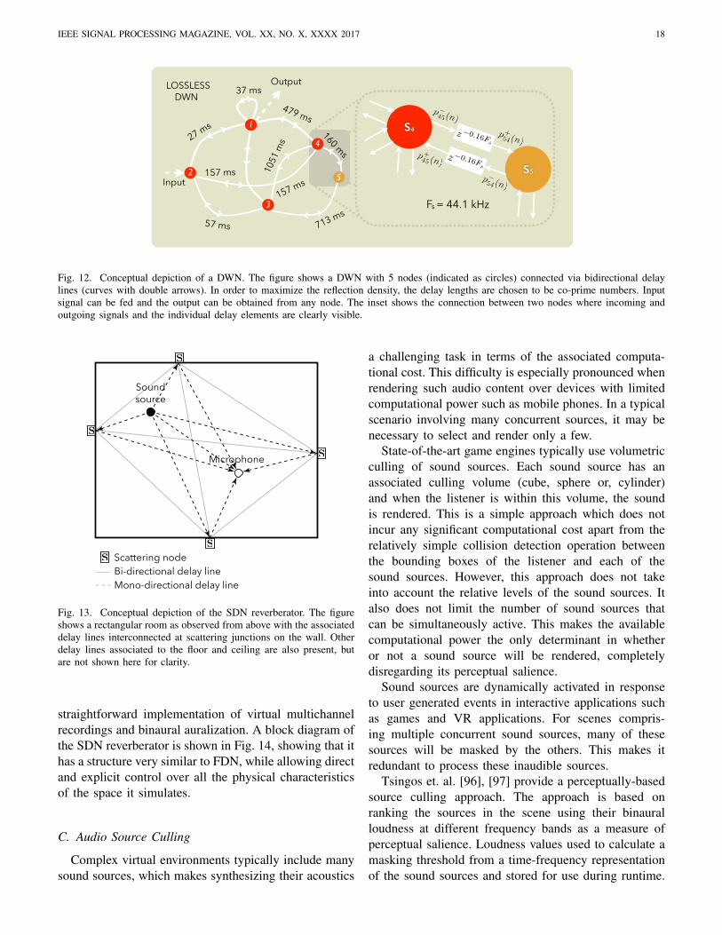
4
Fig. 12. Conceptual depiction of a DWN. The figure shows a DWN with 5 nodes (indicated as circles) connected via bidirectional delaylines (curves with double arrows). In order to maximize the reflection density, the delay lengths are chosen to be co-prime numbers. Inputsignal can be fed and the output can be obtained from any node. The inset shows the connection between two nodes where incoming andoutgoing signals and the individual delay elements are clearly visible.
Soundsource
Microphone
Bi-directional delay lineMono-directional delay line
Scattering node
Fig. 13. Conceptual depiction of the SDN reverberator. The figureshows a rectangular room as observed from above with the associateddelay lines interconnected at scattering junctions on the wall. Otherdelay lines associated to the floor and ceiling are also present, butare not shown here for clarity.
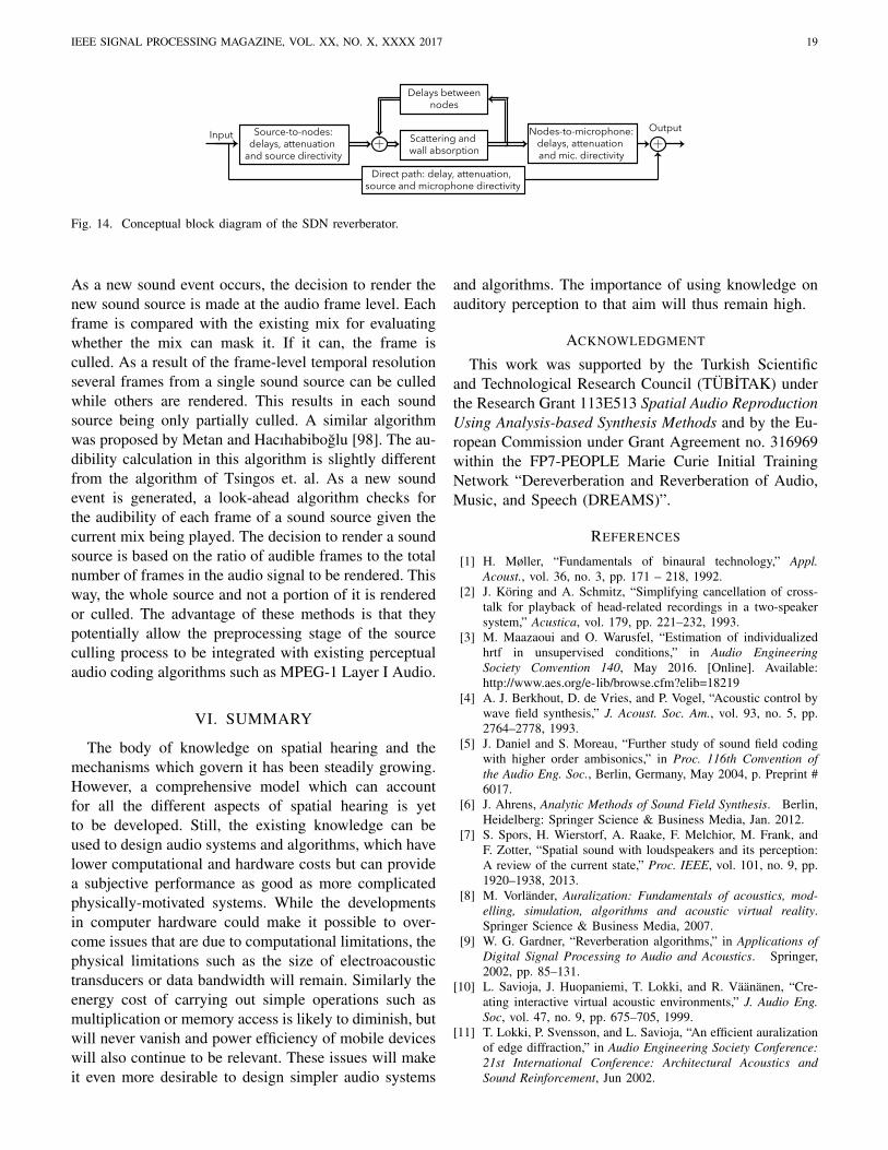
straightforward implementation of virtual multichannelrecordings and binaural auralization. A block diagram ofthe SDN reverberator is shown in Fig. 14, showing that ithas a structure very similar to FDN, while allowing directand explicit control over all the physical characteristicsof the space it simulates.
C. Audio Source Culling
Complex virtual environments typically include manysound sources, which makes synthesizing their acoustics
a challenging task in terms of the associated computa-tional cost. This difficulty is especially pronounced whenrendering such audio content over devices with limitedcomputational power such as mobile phones. In a typicalscenario involving many concurrent sources, it may benecessary to select and render only a few.
State-of-the-art game engines typically use volumetricculling of sound sources. Each sound source has anassociated culling volume (cube, sphere or, cylinder)and when the listener is within this volume, the soundis rendered. This is a simple approach which does notincur any significant computational cost apart from therelatively simple collision detection operation betweenthe bounding boxes of the listener and each of thesound sources. However, this approach does not takeinto account the relative levels of the sound sources. Italso does not limit the number of sound sources thatcan be simultaneously active. This makes the availablecomputational power the only determinant in whetheror not a sound source will be rendered, completelydisregarding its perceptual salience.
Sound sources are dynamically activated in responseto user generated events in interactive applications suchas games and VR applications. For scenes compris-ing multiple concurrent sound sources, many of thesesources will be masked by the others. This makes itredundant to process these inaudible sources.
Tsingos et. al. [96], [97] provide a perceptually-basedsource culling approach. The approach is based onranking the sources in the scene using their binauralloudness at different frequency bands as a measure ofperceptual salience. Loudness values used to calculate amasking threshold from a time-frequency representationof the sound sources and stored for use during runtime.
IEEE SIGNAL PROCESSING MAGAZINE, VOL. XX, NO. X, XXXX 2017 19
Scattering and
wall absorption
Delays between
nodes
Source-to-nodes:
delays, attenuation
and source directivity
Nodes-to-microphone:
delays, attenuation
and mic. directivity
Direct path: delay, attenuation,
source and microphone directivity
OutputInput
Fig. 14. Conceptual block diagram of the SDN reverberator.
As a new sound event occurs, the decision to render thenew sound source is made at the audio frame level. Eachframe is compared with the existing mix for evaluatingwhether the mix can mask it. If it can, the frame isculled. As a result of the frame-level temporal resolutionseveral frames from a single sound source can be culledwhile others are rendered. This results in each soundsource being only partially culled. A similar algorithmwas proposed by Metan and Hacıhabiboglu [98]. The au-dibility calculation in this algorithm is slightly differentfrom the algorithm of Tsingos et. al. As a new soundevent is generated, a look-ahead algorithm checks forthe audibility of each frame of a sound source given thecurrent mix being played. The decision to render a soundsource is based on the ratio of audible frames to the totalnumber of frames in the audio signal to be rendered. Thisway, the whole source and not a portion of it is renderedor culled. The advantage of these methods is that theypotentially allow the preprocessing stage of the sourceculling process to be integrated with existing perceptualaudio coding algorithms such as MPEG-1 Layer I Audio.
VI. SUMMARY
The body of knowledge on spatial hearing and themechanisms which govern it has been steadily growing.However, a comprehensive model which can accountfor all the different aspects of spatial hearing is yetto be developed. Still, the existing knowledge can beused to design audio systems and algorithms, which havelower computational and hardware costs but can providea subjective performance as good as more complicatedphysically-motivated systems. While the developmentsin computer hardware could make it possible to over-come issues that are due to computational limitations, thephysical limitations such as the size of electroacoustictransducers or data bandwidth will remain. Similarly theenergy cost of carrying out simple operations such asmultiplication or memory access is likely to diminish, butwill never vanish and power efficiency of mobile deviceswill also continue to be relevant. These issues will makeit even more desirable to design simpler audio systems
and algorithms. The importance of using knowledge onauditory perception to that aim will thus remain high.
ACKNOWLEDGMENT
This work was supported by the Turkish Scientificand Technological Research Council (TUBITAK) underthe Research Grant 113E513 Spatial Audio ReproductionUsing Analysis-based Synthesis Methods and by the Eu-ropean Commission under Grant Agreement no. 316969within the FP7-PEOPLE Marie Curie Initial TrainingNetwork “Dereverberation and Reverberation of Audio,Music, and Speech (DREAMS)”.
REFERENCES
[1] H. Møller, “Fundamentals of binaural technology,” Appl.Acoust., vol. 36, no. 3, pp. 171 – 218, 1992.
[2] J. Koring and A. Schmitz, “Simplifying cancellation of cross-talk for playback of head-related recordings in a two-speakersystem,” Acustica, vol. 179, pp. 221–232, 1993.
[3] M. Maazaoui and O. Warusfel, “Estimation of individualizedhrtf in unsupervised conditions,” in Audio EngineeringSociety Convention 140, May 2016. [Online]. Available:http://www.aes.org/e-lib/browse.cfm?elib=18219
[4] A. J. Berkhout, D. de Vries, and P. Vogel, “Acoustic control bywave field synthesis,” J. Acoust. Soc. Am., vol. 93, no. 5, pp.2764–2778, 1993.
[5] J. Daniel and S. Moreau, “Further study of sound field codingwith higher order ambisonics,” in Proc. 116th Convention ofthe Audio Eng. Soc., Berlin, Germany, May 2004, p. Preprint #6017.
[6] J. Ahrens, Analytic Methods of Sound Field Synthesis. Berlin,Heidelberg: Springer Science & Business Media, Jan. 2012.
[7] S. Spors, H. Wierstorf, A. Raake, F. Melchior, M. Frank, andF. Zotter, “Spatial sound with loudspeakers and its perception:A review of the current state,” Proc. IEEE, vol. 101, no. 9, pp.1920–1938, 2013.
[8] M. Vorlander, Auralization: Fundamentals of acoustics, mod-elling, simulation, algorithms and acoustic virtual reality.Springer Science & Business Media, 2007.
[9] W. G. Gardner, “Reverberation algorithms,” in Applications ofDigital Signal Processing to Audio and Acoustics. Springer,2002, pp. 85–131.
[10] L. Savioja, J. Huopaniemi, T. Lokki, and R. Vaananen, “Cre-ating interactive virtual acoustic environments,” J. Audio Eng.Soc, vol. 47, no. 9, pp. 675–705, 1999.
[11] T. Lokki, P. Svensson, and L. Savioja, “An efficient auralizationof edge diffraction,” in Audio Engineering Society Conference:21st International Conference: Architectural Acoustics andSound Reinforcement, Jun 2002.
IEEE SIGNAL PROCESSING MAGAZINE, VOL. XX, NO. X, XXXX 2017 20
[12] E. De Sena, H. Hacıhabiboglu, Z. Cvetkovic, and J. O. Smith,“Efficient synthesis of room acoustics via scattering delaynetworks,” IEEE/ACM Trans. on Audio, Speech, and LanguageProcess., vol. 23, no. 9, pp. 1478–1492, September 2015.
[13] J. Blauert, Spatial Hearing: The Psychophysics of Human SoundLocalization. Cambridge, MA, USA: MIT Press, 1997.
[14] B. C. Moore, Hearing. Academic Press, 1995.[15] P. Zahorik, D. S. Brungart, and A. W. Bronkhorst, “Auditory
distance perception in humans: A summary of past and presentresearch,” Acta Acoustica united with Acustica, vol. 91, no. 3,pp. 409–420, 2005.
[16] ——, “Auditory distance perception in humans: A summary ofpast and present research,” Acta Acustica united with Acustica,vol. 91, no. 3, pp. 409–420, 2005.
[17] R. Y. Litovsky, H. S. Colburn, W. A. Yost, and S. J. Guzman,“The precedence effect,” J. Acoust. Soc. Am., vol. 106, no. 4,pp. 1633–1654, 1999.
[18] A. Kulkarni and H. S. Colburn, “Infinite-impulse-responsemodels of the head-related transfer function,” J. Acoust. Soc.Am., vol. 115, no. 4, pp. 1714–1728, 2004.
[19] Y. Luo, D. N. Zotkin, H. Daume, and R. Duraiswami, “Kernelregression for head-related transfer function interpolation andspectral extrema extraction,” in 2013 IEEE Int. Conf. on Acoust.,Speech and Signal Process. (ICASSP’13), May 2013, pp. 256–260.
[20] R. Duraiswami and N. A. Gumerov, “Method for measure-ment of head related transfer functions,” US Patent 7,720,229,May 18 2010.
[21] D. R. Begault, E. M. Wenzel, and M. R. Anderson, “Directcomparison of the impact of head tracking, reverberation, andindividualized head-related transfer functions on the spatialperception of a virtual speech source,” J. Audio Eng. Soc.,vol. 49, no. 10, pp. 904–916, October 2001.
[22] N. I. Durlach, A. Rigopulos, X. D. Pang, W. S. Woods,A. Kulkarni, H. S. Colburn, and E. M. Wenzel, “On theexternalization of auditory images,” Presence: Teleoperatorsand Virtual Environments, vol. 1, no. 2, pp. 251–257, 1992.
[23] D. H. Cooper and J. L. Bauck, “Prospects for transauralrecording,” J. Audio Eng. Soc., vol. 37, no. 1/2, pp. 3–19,January/February 1989.
[24] W. G. Gardner, 3-D audio using loudspeakers. SpringerScience & Business Media, 1998.
[25] ——, “Spatial audio reproduction: Towards individualized bin-aural sound,” in Frontiers of Engineering:: Reports on Leading-Edge Engineering from the 2004 NAE Symposium on Frontiersof Engineering, vol. 34, 2005, p. 113.
[26] N. V. Franssen, Stereophony. Philips Technical Library, 1964.[27] M. Williams, “Unified theory of microphone systems for stereo-
phonic sound recording,” in Proc. 82th Convention of the AudioEng. Soc., London, UK, March 1987, p. Preprint # 2466.
[28] C. Ceoen, “Comparative stereophonic listening tests,” J. AudioEng. Soc, vol. 20, no. 1, pp. 19–27, 1972. [Online]. Available:http://www.aes.org/e-lib/browse.cfm?elib=2104
[29] F. Rumsey and T. McCormick, Sound and recording: an intro-duction. CRC Press, 2012.
[30] E. De Sena, H. Hacıhabiboglu, and Z. Cvetkovic, “Analysisand design of multichannel systems for perceptual sound fieldreconstruction,” IEEE/ACM Trans. on Audio, Speech, and Lan-guage Process., vol. 21, no. 8, pp. 1653–1665, 2013.
[31] B. Bernfeld, “Attempts for better understanding of the direc-tional stereophonic listening mechanism,” in Proc. 44th Con-vention of the Audio Eng. Soc., Rotterdam, the Netherlands,1973, pp. C–4.
[32] J. Steinberg and W. B. Snow, “Auditory perspective-physicalfactors,” Trans. of the Am. Inst. of Elect. Engineers, vol. 1,no. 53, pp. 12–17, 1934.
[33] D. H. Cooper and T. Shiga, “Discrete-matrix multichannelstereo,” J. Audio Eng. Soc., vol. 20, no. 5, pp. 346–360, May1972.
[34] M. A. Gerzon, “Surround-sound psychoacoustics,” WirelessWorld, vol. 80, no. 1468, pp. 483–486, 1974.
[35] G. Theile, “Multichannel natural recording based on psychoa-coustic principles,” in Proc. 108th Convention of the Audio Eng.Soc., Paris, France, 2000, p. Preprint # 5156.
[36] R. Kassier, H.-K. Lee, T. Brookes, and F. Rumsey, “An informalcomparison between surround-sound microphone techniques,”in Proc. 118th Convention of the Audio Eng. Soc., Barcelona,Spain, 2005, p. Preprint # 6429.
[37] U. Herrmann and V. Henkels, “Main microphone techniques forthe 3/2-stereo-standard,” 20th Tonmeister Tagung, 1998.
[38] P. G. Craven and M. A. Gerzon, “Coincident microphone sim-ulation covering three dimensional space and yielding variousdirectional outputs,” US Patent 4,042,779, Aug. 16 1977.
[39] A. Fukada, “A challenge in multichannel music recording,”in Proc. 19th Conf. of Audio Eng. Soc.: Surround Sound -Techniques, Technology, and Perception, Elmau, Germany, June2001, p. 1881.
[40] K. Hamasaki and K. Hiyama, “Reproducing spatial impressionwith multichannel audio,” in Proc. 24th Conf. of Audio Eng.Soc.: Multichannel Audio, The New Reality, Banff, Canada,June 2003, p. 19.
[41] K. Hamasaki, “22.2 multichannel audio format standardizationactivity,” Broadcast Tech., vol. 45, pp. 14–19, 2011.
[42] V. Pulkki, “Virtual sound source positioning using vector baseamplitude panning,” J. Audio Eng. Soc., vol. 45, no. 6, pp. 456–466, June 1997.
[43] V. Pulkki and M. Karjalainen, “Localization of amplitude-panned virtual sources I: stereophonic panning,” J. Audio Eng.Soc., vol. 49, no. 9, pp. 739–752, September 2001.
[44] V. Pulkki, “Localization of amplitude-panned virtual sourcesII: Two-and three-dimensional panning,” J. Audio Eng. Soc.,vol. 49, no. 9, pp. 753–767, September 2001.
[45] ——, “Uniform spreading of amplitude panned virtual sources,”in Proc. IEEE Workshop on Appl. of Signal Process. to Audioand Acoust. (WASPAA’99), New Paltz, NY, USA, October 1999,pp. 187 – 190.
[46] M. Frank, “Localization using different amplitude-panningmethods in the frontal horizontal plane,” in Proc. of the EAAJoint Symp. on Auralization and Ambisonics, Berlin, Germany,2014, pp. 41–47.
[47] T. Sporer, J. Liebetrau, S. Werner, S. Kepplinger, T. Gabb,and T. Sieder, “Localization of audio objects in multichannelreproduction systems,” in Proc. 57th Conf. of Audio Eng. Soc.:The Future of Audio Entertainment Technology – Cinema,Television and the Internet, Mar 2015, pp. 7–2. [Online].Available: http://www.aes.org/e-lib/browse.cfm?elib=17613
[48] R. Baumgartner, P. Majdak, and B. Laback, “Assessmentof sagittal-plane sound localization performance in spatial-audio applications,” in The Technology of Binaural Listening.Springer, 2013, pp. 93–119.
[49] J. Merimaa and V. Pulkki, “Spatial impulse response renderingI: Analysis and synthesis,” J. Audio Eng. Soc., vol. 53, no. 12,pp. 1115–1127, 2005.
[50] V. Pulkki and J. Merimaa, “Spatial impulse response renderingII: Reproduction of diffuse sound and listening tests,” J. AudioEng. Soc., vol. 54, no. 1/2, pp. 3–20, January/February 2006.
[51] S. Tervo, J. Patynen, A. Kuusinen, and T. Lokki, “Spatialdecomposition method for room impulse responses,” J. AudioEng. Soc., vol. 61, no. 1/2, pp. 17–28, 2013.
[52] V. Pulkki, “Spatial sound reproduction with directional audiocoding,” J. Audio Eng. Soc., vol. 55, no. 6, pp. 503–516, June2007.
IEEE SIGNAL PROCESSING MAGAZINE, VOL. XX, NO. X, XXXX 2017 21
[53] J. Vilkamo, T. Lokki, and V. Pulkki, “Directional audio coding:Virtual microphone-based synthesis and subjective evaluation,”J. Audio Eng. Soc., vol. 57, no. 9, pp. 709–724, September2009.
[54] J. D. Johnston and Y. H. V. Lam, “Perceptual soundfieldreconstruction,” in Proc. 109th Convention of the Audio Eng.Soc., Los Angeles, CA, USA, September 2000, p. Preprint #5202.
[55] E. De Sena and Z. Cvetkovic, “A computational model forthe estimation of localisation uncertainty,” in Proc. IEEE Int.Conf. on Acoust., Speech and Signal Process. (ICASSP’13),Vancouver, BC, Canada, May 2013, pp. 388–392.
[56] E. De Sena, H. Hacihabiboglu, and Z. Cvetkovic, “On thedesign and implementation of higher order differential micro-phones,” IEEE Trans. on Audio, Speech and Language Process.,vol. 20, no. 1, pp. 162–174, January 2012.
[57] J. Benesty and C. Jingdong, Study and design of differentialmicrophone arrays. Springer Science & Business Media, 2013.
[58] R. M. Aarts, “Enlarging the sweet spot for stereophony bytime/intensity trading,” in Proc. 94th Convention of the AudioEng. Soc., Berlin, Germany, March 1993, p. Preprint # 3473.
[59] J. A. Rodenas and R. M. Aarts, “Position independent stereo-phonic sound reproduction,” J. Acoust. Soc. Netherlands, no.153, pp. 37–47, November 2000.
[60] J. A. Rodenas, R. M. Aarts, and A. Janssen, “Derivation ofan optimal directivity pattern for sweet spot widening in stereosound reproduction,” J. Acoust. Soc. Am., vol. 113, no. 1, pp.267–278, January 2003.
[61] V. Valimaki, J. D. Parker, L. Savioja, J. O. Smith, and J. S. Abel,“Fifty years of artificial reverberation,” IEEE Trans. on Audio,Speech and Language Process., vol. 20, no. 5, pp. 1421–1448,May 2012.
[62] J. B. Allen and D. A. Berkley, “Image method for efficientlysimulating small-room acoustics,” J. Acoust. Soc. Am., vol. 65,no. 4, pp. 943–950, April 1979.
[63] J. Borish, “Extension of the image model to arbitrary polyhe-dra,” J. Acoust. Soc. Am., vol. 75, no. 6, pp. 1827–1836, June1984.
[64] A. Krokstad, S. Strom, and S. Sørsdal, “Calculating the acous-tical room response by the use of a ray tracing technique,” J.Sound Vib., vol. 8, no. 1, pp. 118–125, August 1968.
[65] A. Kulowski, “Algorithmic representation of the ray tracingtechnique,” Appl. Acoust., vol. 18, no. 6, pp. 449–469, June1985.
[66] A. Farina, “RAMSETE-a new pyramid tracer for medium andlarge scale acoustic problems,” in Proc. 2nd European Conf. onNoise Control (Euronoise’95), Lyon, France, March 1995.
[67] K. Kowalczyk and M. van Walstijn, “Room acoustics simulationusing 3-d compact explicit fdtd schemes,” IEEE Trans. onAudio, Speech and Language Process., vol. 19, no. 1, pp. 34–46,2011.
[68] S. A. Van Duyne and J. O. Smith, “The tetrahedral digitalwaveguide mesh,” in Proc. IEEE Workshop on Appl. of SignalProcess. to Audio and Acoust. (WASPAA’95), October 1995, pp.234–237.
[69] T. Shuku and K. Ishihara, “The analysis of the acoustic fieldin irregularly shaped rooms by the finite element method,” J.Sound Vib., vol. 29, no. 1, pp. 67–76, January 1973.
[70] S. M. Kirkup, The boundary element method in acoustics.Integrated Sound Software, 2007.
[71] J. M. Buchholz, J. Mourjopoulos, and J. Blauert, “Roommasking: understanding and modelling the masking of roomreflections,” in Proc. 110th Convention of the Audio Eng. Soc.,Amsterdam, the Netherlands, May 2001, p. Preprint # 5312.
[72] D. R. Begault, “Audible and inaudible early reflections: thresh-olds for auralization system design,” in Proc. 100th Conv. of the
Audio Eng. Soc., Copenhagen, Denmark, May 1996, p. Preprint# 4244.
[73] D. R. Begault, B. U. McClain, and M. R. Anderson, “Earlyreflection thresholds for virtual sound sources,” in Proc. 2001Int. Workshop on Spatial Media, 2001.
[74] ——, “Early reflection thresholds for anechoic and reverberantstimuli within a 3-d sound display,” in Proc. 18th Int. Congresson Acoust. (ICA’04), Kyoto, Japan, 2004.
[75] H. Hacıhabiboglu and F. Murtagh, “An observational studyof the precedence effect,” Acta acustica united with acustica,vol. 92, no. 3, pp. 440–456, March 2006.
[76] ——, “Perceptual simplification for model-based binaural roomauralisation,” Appl. Acoust., vol. 69, no. 8, pp. 715–727, August2008.
[77] C. Schissler and D. Manocha, “Adaptive impulse responsemodeling for interactive sound propagation,” in Proc. 20thACM SIGGRAPH Symp. Interactive 3D Graphics and Games,Redmond, WA, USA, February 2016, pp. 71–78.
[78] F. Rumsey, Spatial audio. Focal Press, 2001.[79] M. Barron and A. H. Marshall, “Spatial impression due to early
lateral reflections in concert halls: the derivation of a physicalmeasure,” Journal of Sound and Vibration, vol. 77, no. 2, pp.211–232, 1981.
[80] H. Kuttruff, Room acoustics. Crc Press, 2009.[81] J. S. Abel and P. Huang, “A simple, robust measure of rever-
beration echo density,” in Proc. 121st Convention of the AudioEng. Soc., San Francisco, CA, USA, October 2006, p. Preprint# 6985.
[82] M. Karjalainen and H. Jarvelainen, “More about this reverber-ation science: Perceptually good late reverberation,” in Proc.111th Convention of the Audio Eng. Soc., New York, NY, USA,November 2001, p. Preprint # 5415.
[83] S. Favrot and J. M. Buchholz, “LoRA: A loudspeaker-basedroom auralization system,” Acta Acustica united with Acustica,vol. 96, no. 2, pp. 364–375, February 2010.
[84] T. Okamoto, B. F. Katz, M. Noisternig, Y. Iwaya, and Y. Suzuki,“Implementation of real-time room auralization using a sur-rounding 157 loudspeaker array,” in Proc. Int. Workshop onthe Principles and Applications of Spatial Hearing (IWPASH2009), Sendai, Japan, November 2009, pp. 373–382.
[85] M. R. Schroeder, “Natural sounding artificial reverberation,” J.Audio Eng. Soc., vol. 10, no. 3, pp. 219–223, March 1962.
[86] J. A. Moorer, “About this reverberation business,” Comp. MusicJ., vol. 3, no. 2, pp. 13–28, 1979.
[87] J.-M. Jot and A. Chaigne, “Digital delay networks for designingartificial reverberators,” in Proc. 90th Convention of the AudioEng. Soc., Paris, France, February 1991, p. Preprint # 3030.
[88] J. Stautner and M. Puckette, “Designing multi-channel rever-berators,” Comp. Music J., vol. 6, no. 1, pp. 52–65, 1982.
[89] D. Rocchesso, “Maximally diffusive yet efficient feedback delaynetworks for artificial reverberation,” IEEE Signal Process.Lett., vol. 4, no. 9, pp. 252–255, September 1997.
[90] F. Menzer and C. Faller, “Unitary matrix design for diffuse Jotreverberators,” in Proc. 128th Convention of the Audio Eng.Soc., London, UK, June 2010, p. Preprint # 7984.
[91] S. J. Schlecht and E. A. Habets, “Time-varying feedbackmatrices in feedback delay networks and their application inartificial reverberation,” J. Acoust. Soc. Am., vol. 138, no. 3,pp. 1389–1398, March 2015.
[92] J. Smith, “Digital signal processing using closed waveguidenetworks,” US Patent 5,448,010, Sep. 5 1995.
[93] G. Kendall, W. Martens, D. Freed, D. Ludwig, and R. Karstens,“Image model reverberation from recirculating delays,” in Proc.81st Convention of the Audio Eng. Soc., Los Angeles, CA, USA,November 1986, p. Preprint # 2408.
IEEE SIGNAL PROCESSING MAGAZINE, VOL. XX, NO. X, XXXX 2017 22
[94] T. Wendt, S. Van De Par, and S. D. Ewert, “A computationally-efficient and perceptually-plausible algorithm for binaural roomimpulse response simulation,” J. Audio Eng. Soc., vol. 62,no. 11, pp. 748–766, 2014.
[95] P. Huang, M. Karjalainen, and J. O. Smith, “Digital waveguidenetworks for room response modeling and synthesis,” in Proc.118th Convention of the Audio Eng. Soc., Barcelona, Spain,May 2005, p. Preprint # 6394.
[96] N. Tsingos, E. Gallo, and G. Drettakis, “Perceptual audio ren-dering of complex virtual environments,” ACM Trans. Graph.,vol. 23, no. 3, pp. 249–258, August 2004.
[97] N. Tsingos, “Scalable perceptual mixing and filtering of audiosignals using an augmented spectral representation,” in Proc.8th Int. Conf. on Digital Audio Effects (DAFx-05), 2005.
[98] A. C. Metan and H. Hacıhabiboglu, “Perceptual audio sourceculling for virtual environments,” in Proc. 19th Int. Conf. onDigital Audio Effects (DAFx-16), 2016.
Huseyin Hacıhabiboglu (S’96-M’00-SM’12) received the B.Sc.(honors) degree from the Middle East Technical University (METU),Ankara, Turkey, in 2000, the M.Sc. degree from the Universityof Bristol, Bristol, U.K., in 2001, both in electrical and electronicengineering, and the Ph.D. degree in computer science from QueensUniversity Belfast, Belfast, U.K., in 2004. He held research positionsat University of Surrey, Guildford, U.K. (2004-2008) and KingsCollege London, London, U.K. (2008-2011). Currently, he is anAssociate Professor of Signal Processing and the Head of Departmentof Modelling and Simulation at Graduate School of Informatics,Middle East Technical University (METU), Ankara, Turkey. He alsocoordinates the recently established Multimedia Informatics graduateprogram at the same department. His research interests includeaudio signal processing, room acoustics, multichannel audio systems,psychoacoustics of spatial hearing, microphone arrays, and gameaudio. He is a member of the IEEE Signal Processing Society, AudioEngineering Society (AES), Turkish Acoustics Society (TAD), andthe European Acoustics Association (EAA).
Enzo De Sena (S’11-M’14) received the B.Sc. in 2007 and M.Sc.cum laude in 2009, both from the Universita degli Studi di NapoliFederico II in Telecommunication Engineering. In 2013, he receivedthe Ph.D. degree in Electronic Engineering from Kings CollegeLondon, where he was also a Teaching Fellow from 2012 to 2013.Between 2013 and 2016 he was a Postdoctoral Research Fellowat the Department of Electrical Engineering of KU Leuven. SinceSeptember 2016 he is a Lecturer (Assistant Professor) in Audioat the Institute of Sound Recording of the University of Surrey.He held visiting positions at the Center for Computer Research inMusic and Acoustics at Stanford University (2013), at the Signal andInformation Processing section at Aalborg University (2014-2015)and at the Speech and Audio Processing Group at Imperial CollegeLondon (2016). He is a former Marie Curie fellow. His currentresearch interests include room acoustics modelling, multichannelaudio systems, microphone beamforming and binaural modelling.
Zoran Cvetkovic (SM’04) is Professor of Signal Processing atKings College London. He received his Dipl. Ing. and Mag. degreesfrom the University of Belgrade, Yugoslavia, the M.Phil. fromColumbia University, and the Ph.D. in electrical engineering fromthe University of California, Berkeley. He held research positionsat EPFL, Lausanne, Switzerland (1996), and at Harvard University(2002-04). Between 1997 and 2002 he was a member of the technicalstaff of AT&T Shannon Laboratory. His research interests are in thebroad area of signal processing, ranging from theoretical aspects ofsignal analysis to applications in audio and speech technology, andneuroscience. From 2005 to 2008 he served as an Associate Editorof IEEE Transactions on Signal Processing.
James Johnston (F’02) received his BSEE and MSEE fromCarnegie-Mellon University. He has worked on audio and acousticsignal processing in various research labs and companies such asAT&T Bell Laboratories, AT&T Labs, Neural Audio and Microsoftamong others. He was the primary researcher and inventor of theMPEG-2 AAC audio coding algorithm, and a principal contributor tothe ”MP3” algorithm. Mr. Johnston was awarded the IEEE James L.Flanagan Signal Processing Field Award (2006); elected Fellow, Au-dio Engineering Society (1997); received AT&T Technology Medaland AT&T Standards Award (1998); received a New Jersey Inventorof the Year Award (2001); elected IEEE Fellow (2002). He wasa distinguished lecturer of the IEEE Signal Processing Society in2011. His current research interests include acoustic scene modelling,loudspeaker design, loudspeaker pattern control, cochlear modelling,masking threshold models, stereo imaging models and stereo imagingsensitivity models, methods of reproducing sound fields, microphoneand sound field capture techniques, both actively steered and time-invariant, and speech and audio coding methods in general.
Julius O. Smith III received the B.S.E.E. degree from Rice Univer-sity, Houston, TX, in 1975 (Control, Circuits, and Communication).He received the M.S. and Ph.D. degrees in E.E. from StanfordUniversity, Stanford, CA, in 1978 and 1983, respectively. His Ph.D.research was devoted to improved methods for digital filter designand system identification applied to music and audio systems. From1975 to 1977 he worked in the Signal Processing Department atESL, Sunnyvale, CA, on systems for digital communications. From1982 to 1986 he was with the Adaptive Systems Department atSystems Control Technology, Palo Alto, CA, where he worked inthe areas of adaptive filtering and spectral estimation. From 1986to 1991 he was employed at NeXT Computer, Inc., responsible forsound, music, and signal processing software for the NeXT computerworkstation. After NeXT, he became an Associate Professor at theCenter for Computer Research in Music and Acoustics (CCRMA)at Stanford, teaching courses and pursuing research related to signalprocessing techniques applied to music and audio systems. Continu-ing this work, he is presently Professor of Music and (by courtesy)Electrical Engineering at Stanford University. For more information,see http://ccrma.stanford.edu/˜jos/.