Embed Size (px)
Citation preview

REFRIGERATION(PENDINGINAN)
Jurusan Teknologi Hasil Pertanian Fakultas Pertanian Universitas Lampung
Oleh: Ribut Sugiharto
1
Jurusan Teknologi Hasil Pertanian Fakultas Pertanian Universitas Lampung
PENDAHULUAN
455
Temperature plays an important role in maintaining the quality of stored food products. Lowering the temperature retards the rates of reactions that cause quality deterioration. It is generally agreed that the reaction rate is reduced by half by lowering the temperature by 10°C.
In earlier days, a lower temperature was obtained by the use of ice. Ice was allowed to melt in an insulated chamber that contained food prod-ucts ( Fig. 6.1 ). During melting, ice requires latent heat (333.2 kJ/kg) to be converted from the solid phase to liquid water. This heat was extracted from the product that was kept next to ice in an insulated chamber.
Today, the cooling process is achieved by the use of a mechanical refrigeration system. Refrigeration systems allow transfer of heat from the cooling chamber to a location where the heat can easily be dis-carded. The transfer of heat is accomplished by using a refrigerant,which like water changes state—from liquid to vapor. Unlike water,a refrigerant has a much lower boiling point. For example, ammonia,a commonly used refrigerant in industrial plants, has a boiling point of !33.3°C. This is a much lower temperature compared with 100°C,the boiling point of water at atmospheric pressure. Similar to water,ammonia needs latent heat to change its phase from liquid to gas at its boiling point. The boiling point of a refrigerant can be varied by changing the pressure. Thus, to increase the boiling point of ammo-nia to 0°C, its pressure must be raised to 430.43 kPa.
A very simple refrigeration system that utilizes a refrigerant is shown in Figure 6.2 . The only drawback in this illustration is the onetime use of the refrigerant. Because refrigerants are expensive, they must
6 Refrigeration
Chapter
All icons in this chapter refer to the author’s web site, which is independently owned and operated. Academic Press is not responsible for the content or operation of the author’s web site. Please direct your web site comments and questions to the author: Professor R. Paul Singh, Department of Biological and Agricultural Engineering, University of California, Davis, CA 95616, USA. Email: [email protected].
Ice
■ Figure 6.1 An ice box.2
Jurusan Teknologi Hasil Pertanian Fakultas Pertanian Universitas Lampung
3
Jurusan Teknologi Hasil Pertanian Fakultas Pertanian Universitas Lampung
PENDAHULUANDasar Pendinginan: • Pendinginan menurunkan reaksi biologi. • Penuruan suhu 10oC, menurunkan laju reaksi 50%. • Meningkatkan lama penyimpanan.Jenis Media Penyerap Panas 1. Air (Es)
• Es mencair memerlukan panas latent (333,2 kJ/kg). • Panas diserap dari lingkungannya.
2. Refrigenant. • Mechanical refrigeration system. • mempunyai titik didih sangat rendah (<15oC) dan suhu
kondensasi tinggi (>30oC). • Contoh: freon (12, 22, 30, 134a), amonia.
4

Jurusan Teknologi Hasil Pertanian Fakultas Pertanian Universitas Lampung
SYARAT REFRIGRANTa. Panas latent penguapan besar. b. Tekanan kondesasi rendah. c. Suhu pembekuan dibawah suhu penguapan. d. Suhu kritis tinggi, lebih tinggi suhu kamar. e. Tidak beracun. f. Tidak mudah terbakar. g. Tidak menyebabkan korosi. h. Secara kimia stabil. i. Mudah dideteksi bila terjadi kebocoran. j. Murah. k. Tidak merusak lingkungan. !
ASHRAE Standard No. 34-1978
5
Jurusan Teknologi Hasil Pertanian Fakultas Pertanian Universitas Lampung
458 CHAPTER 6 Refrigeration
A number of refrigerants used in commercial practice are halocar-bons, although their use is being severely curtailed as described later in this section. Refrigerant-12, also called Freon 12, is a dichlorodi-fl uoromethane. Its latent heat of vaporization is low compared with ammonia (R-717); therefore, considerably more weight of the refrig-erant must be circulated to achieve the same refrigeration capacity.
Table 6.1 Comparison between Commonly Used Refrigerants (Performance Based on !15°C Evaporator Temperature and 30°C Condenser Temperature)
Chemical formula
Freon 12(dichlorodifl uoro-
methane, CCl2F2)
Freon 22(monochlorodi-fl uoro-methane,
CHClF2)HFC 134a (CH2FCF3)
Ammonia (NH3)
Molecular weight 120.9 86.5 102.3 17.0
Boiling point (°C) at 101.3 kPa !29.8 !40.8 !26.16 !33.3
Evaporator pressure at !15°C (kPa) 182.7 296.4 164.0 236.5
Condensing pressure at 30°C (kPa) 744.6 1203.0 770.1 1166.5
Freezing point (°C) at 101.3 kPa !157.8 !160.0 !96.6 !77.8
Critical temperature (°C) 112.2 96.1 101.1 132.8
Critical pressure (kPa) 4115.7 4936.1 4060 11423.4
Compressor discharge temperature (°C)
37.8 55.0 43 98.9
Compression ratio (30°C/!15°C) 4.07 5.06 4.81 4.94
Latent heat of vaporization at !15°C (kJ/kg)
161.7 217.7 209.5 1314.2
Horsepower/ton refrigerant, ideal 1.002 1.011 1.03 0.989
Refrigerant circulated/ton refrigeration (kg/s), ideal
2.8 " 10!2 2.1 " 10!2 2.38 " 10!2 0.31 " 10!2
Compressor displacement/ton refrigeration (m3/s)
2.7 " 10!3 1.7 " 10!3 2.2 " 10!3 1.6 " 10!3
Stability (toxic decomposition products)
Yes Yes No (at high temperatures)
No
Flammability None None None Yes
Odor Ethereal Ethereal Ethereal Acrid
JENIS REFRIGRANT
6
Jurusan Teknologi Hasil Pertanian Fakultas Pertanian Universitas Lampung
KOMPONEN SISTEM REFRIGERASI
!
COMPRESSOR
!
CONDENSER
!
EVAPORATOR
EXPANSION VALVE
A
B
C
D
E
7
Jurusan Teknologi Hasil Pertanian Fakultas Pertanian Universitas Lampung
EVAPORATOR
462 CHAPTER 6 Refrigeration
be used as a carrier medium if the temperature stays above freezing. For lower temperatures, brine (a proper concentration of CaCl 2) or glycols, such as ethylene or propylene glycol, are commonly used.
The evaporators are either bare-pipe, fi nned-tube, or plate type, as shown in Figure 6.4 . Bare-pipe evaporators are most simple, easy to defrost and clean. The fi ns added to the fi nned-tube evaporators allow increase in surface area, thus increasing the rate of heat transfer. The plate evaporators allow an indirect contact between the product (e.g., a liquid food) to be cooled and the refrigerant.
Evaporators can also be classifi ed as direct-expansion and fl ooded types. In the direct-expansion type of evaporators, there is no recircu-lation of the refrigerant within the evaporator. The liquid refrigerant changes to gas as it is conveyed through a continuous tube. In con-trast, the fl ooded evaporator allows recirculation of liquid refrigerant. The liquid refrigerant, after going through the metering device, enters a surge chamber. As shown in Figure 6.5 , the liquid refrigerant boils
Bare pipe Finned tube Plate
■ Figure 6.4 Diff erent types of evaporator coils. (Courtesy of Carrier Co.)
Gas tocompressor
Gas tocompressor
Liquid
Liquid
Direct expansion Flooded
■ Figure 6.5 A direct-expansion evaporator and a fl ooded-type evaporator. (Courtesy of Carrier Co.)
Fungsi: • Tempat refrigerant berubah fase dari cair menjadi uap/gas. • Memerlukan panas latent dan menyerap panas dari
lingkungannya. Jenis: 1. Direct expansion,
• Refrigerant menguap pada koil, dan koil menyerap panas lang dari lingkungannya.
2. Indirect expansion, • Refrigerant mendinginkan medium (air, brine, glycol),
yang kemudian dipompakan ke bahan yang didinginkan.
8

Jurusan Teknologi Hasil Pertanian Fakultas Pertanian Universitas Lampung
COMPRESSORFungsi: Meningkatkan tekanan dan (suhu) refrigerant.
463
in the evaporator coil and extracts heat from the surroundings. The liquid refrigerant is recirculated through the surge tank and the evapo-rator coil. The refrigerant gas leaves the surge tank for the compressor.
6.2.2 Compressor The refrigerant enters the compressor in a vapor state at low pressure and temperature. The compressor raises the pressure and temperature of the refrigerant. It is due to this action of the compressor that heat can be discharged by the refrigerant in the condenser. The compres-sion processes raise the temperature of the refrigerant suffi ciently above the ambient temperature surrounding the condenser, so that the temperature gradient between the refrigerant and the ambient promotes the heat fl ow from the refrigerant to the ambient.
The three common types of compressors are reciprocating, centrifugal,and rotary. As is evident from the name, the reciprocating compressor contains a piston that travels back and forth in a cylinder (as shown in Fig. 6.6 ). Reciprocating compressors are most commonly used and vary in capacity from a fraction of a ton to 100 tons of refrigeration per unit (for defi nition of ton of refrigeration, see Section 6.4.1). The centrifugal com-pressor contains an impeller with several blades that turn at high speed. The rotary compressor involves a vane that rotates inside a cylinder.
The compressor may be operated with an electric motor or an inter-nal combustion engine. Figure 6.7 shows a typical installation of a reciprocating compressor operated with an electric motor.
Clearance
D
L
■ Figure 6.6 Operation of a cylinder.
Compressor Evaporator coils
Electric motor
■ Figure 6.7 A typical compression refrigeration system of a two-cylinder, air-cooled condenser driven by an electric motor.
6.2 Components of a Refrigeration System
9
Jurusan Teknologi Hasil Pertanian Fakultas Pertanian Universitas Lampung
CONDENSERFungsi: • Transfer panas dari refrigerant
ke sekelilingnya (udara, air). • M e n g u b a h f a s e u a p
refrigerant menjadi fase cair.
Jenis: 1. Berpendingin udara. 2. Berpendingin air. 3. Evaporasi (udara + air)
10
Jurusan Teknologi Hasil Pertanian Fakultas Pertanian Universitas Lampung
CONDENSER
467
Air-cooled condensers can be either tube-and-fi n type or plate type,as shown in Figure 6.10 . Fins on tubes allow a large heat transfer area in a compact case. The plate condensers have no fi ns, so they require considerably larger surface areas. However, they are cheaper to con-struct and require little maintenance. Both these types of condensers can be found in household refrigerators.
Air-cooled condensers can also employ artifi cial movement of air by using a fan. The fan helps in obtaining higher convective heat-transfer coeffi cients at the surface of the condenser.
Water
Water
Water
Water
Water
Double pipeOpen shell and tube
Hot gas
Liquidrefrigerant
■ Figure 6.9 An open shell-and-tube condenser and double-pipe condenser. (Courtesy of Carrier Co.)
■ Figure 6.10 A plate and tube-and-fi n condenser. (Courtesy of Carrier Co.)
6.2 Components of a Refrigeration System
Jenis berpendingin air: 1. Open shell and tube. 2. Double pipe. 3. Plate. 4. Tube and Fin.
J e n i s b e r p e n d i n g i n udara: 1. Plate. 2. Tube and Fin
11
Jurusan Teknologi Hasil Pertanian Fakultas Pertanian Universitas Lampung
Evaporative Condenser
CONDENSER
12
Jurusan Teknologi Hasil Pertanian Fakultas Pertanian Universitas Lampung
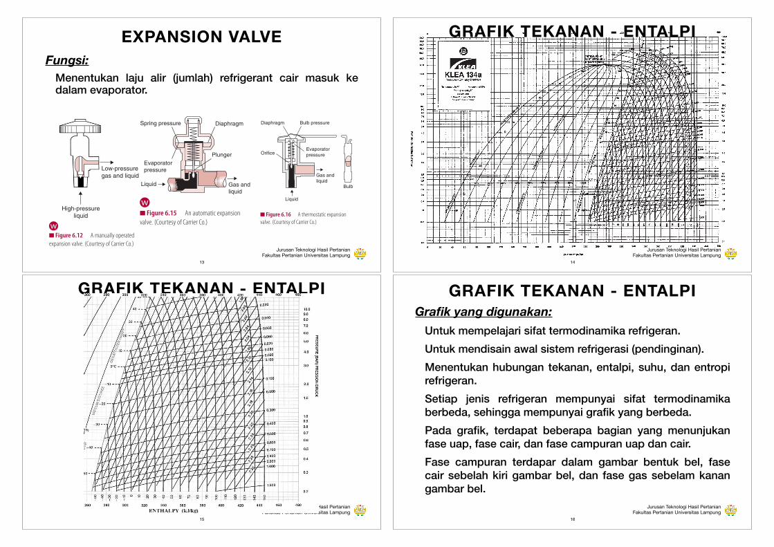
EXPANSION VALVEFungsi: • Menentukan laju alir (jumlah) refrigerant cair masuk ke
dalam evaporator.
468 CHAPTER 6 Refrigeration
In evaporative condensers, a circulating water pump draws water from a pan at the base of the condenser and sprays the water onto the coils. In addition, a large amount of air is drawn over the condenser coils. Evaporation of water requires latent heat, which is extracted from the refrigerant. Figure 6.11 shows an evaporative condenser. These units can be quite large.
6.2.4 Expansion Valve An expansion valve is essentially a metering device that controls the fl ow of liquid refrigerant to an evaporator. The valve can be operated either manually or by sensing pressure or temperature at another desired location in the refrigeration system.
The common type of metering devices used in the refrigeration sys-tem include (1) manually operated expansion valve, (2) automatic low-side fl oat valve, (3) automatic high-side fl oat valve, (4) automatic expansion valve, and (5) thermostatic expansion valve.
A simple, manually operated expansion valve is shown in Figure 6.12 . The valve, manually adjusted, allows a desired amount of fl ow of refrigerant from the high-pressure liquid side to the low-pressure gas/liquid side. The refrigerant cools as it passes through the valve. The heat given up by the liquid refrigerant is absorbed to convert some of
Moist airexit
Motor
Fans
Eliminator
Finnedtubes
Circulatingpump
Sludge drain
Receiver
Liquidreturn
Hot gasinlet Air inlet
■ Figure 6.11 An evaporative condenser. (From Jennings, 1970. Copyright © 1939, 1944, 1949, 1956, 1958, 1970 by Harper and Row, Publishers, Inc. Reprinted with permission of the publisher.)
Low-pressuregas and liquid
High-pressureliquid
■ Figure 6.12 A manually operated expansion valve. (Courtesy of Carrier Co.)
w
470 CHAPTER 6 Refrigeration
fl oat consequently rises and opens the orifi ce, allowing the refrigerant to fl ow to the evaporator.
The automatic expansion valve maintains a constant pressure in the evaporator. As shown in Figure 6.15 , an increase in evaporator pres-sure causes the diaphragm to rise against the spring pressure, which results in the valve closing. The valve opens when the evaporator pressure decreases. This valve is used in applications that require a constant refrigeration load and constant evaporator temperature—for example, in a household refrigerator.
Thermal expansion valves contain a thermostatic bulb clamped to the side of the suction pipe to the compressor ( Fig. 6.16 ). The thermo-static bulb senses the temperature of the superheated gas leaving the evaporator. The relatively high temperature of the thermostatic bulb causes the fl uid in the bulb (usually the same refrigerant) to increase in pressure. The increased pressure is transmitted via the thermo-static tube to the bellows and the diaphragm chamber. The valve consequently opens to allow more liquid refrigerant to fl ow through. Thermostatic valves are the most widely used of all metering devices in the refrigeration industry.
6.3 PRESSURE–ENTHALPY CHARTS Both pressure and enthalpy of the refrigerant change as the refrigerant is conveyed through various components of a refrigeration system. In both the evaporator and the condenser, the enthalpy of the refriger-ant changes and the pressure remains constant. During the compres-sion step, work is done by the compressor, resulting in an increase in the enthalpy of the refrigerant along with an increase in pressure. The expansion valve is a constant-enthalpy process that allows the liquid refrigerant under high pressure to pass at a controlled rate into the low-pressure section of the refrigeration system.
Charts or diagrams have been used extensively in the literature to present thermodynamic properties of refrigerants. These charts are particularly useful during the early, conceptual stages of a refrigera-tion system design. Looking at a chart, we can easily comprehend a standard process, as well as any deviations from the standard. Most commonly used charts depict enthalpy and pressure values on the xand y axes, respectively. Another type of chart involves entropy and temperature values plotted along x and y axes, respectively. The entire
Bulb pressure
Bulb
Evaporatorpressure
Diaphragm
Orifice
Gas andliquid
Liquid
■ Figure 6.16 A thermostatic expansion valve. (Courtesy of Carrier Co.)
Spring pressure
Evaporatorpressure
Liquid Gas andliquid
Plunger
Diaphragm
■ Figure 6.15 An automatic expansion valve. (Courtesy of Carrier Co.)
w
13
Jurusan Teknologi Hasil Pertanian Fakultas Pertanian Universitas Lampung
GRAFIK TEKANAN - ENTALPI811
■ Figure A.6.4 Pressure–enthalpy diagram of R-134a. (Alternate P-H diagram with a datum of 200 kJ/kg AT 0°C is available from DuPont Fluorochemicals, Wilmington, Delaware, USA.)
A.6 Pressure–Enthalpy Data
14
Jurusan Teknologi Hasil Pertanian Fakultas Pertanian Universitas Lampung
GRAFIK TEKANAN - ENTALPI 812Appendices
■ Figure A.6.5 Pressure–enthalpy diagram of R-134a (expanded scale). (Courtesy, ICI Co.) 15
Jurusan Teknologi Hasil Pertanian Fakultas Pertanian Universitas Lampung
GRAFIK TEKANAN - ENTALPIGrafik yang digunakan: • Untuk mempelajari sifat termodinamika refrigeran. • Untuk mendisain awal sistem refrigerasi (pendinginan). • Menentukan hubungan tekanan, entalpi, suhu, dan entropi
refrigeran. • Setiap jenis refrigeran mempunyai sifat termodinamika
berbeda, sehingga mempunyai grafik yang berbeda. • Pada grafik, terdapat beberapa bagian yang menunjukan
fase uap, fase cair, dan fase campuran uap dan cair. • Fase campuran terdapar dalam gambar bentuk bel, fase
cair sebelah kiri gambar bel, dan fase gas sebelam kanan gambar bel.
16

Jurusan Teknologi Hasil Pertanian Fakultas Pertanian Universitas Lampung
471
refrigeration cycle comprising evaporator, compressor, condenser,and expansion valve can be conveniently depicted on the pressure–enthalpy charts. Figure A.6.1 (in the appendix) is a pressure–enthalpy chart for Freon R-12 refrigerant. In this chart, which conforms to the specifi cations of the International Institute of Refrigeration (IIR), the value of the enthalpy of saturated liquid is assumed to be 200 kJ/kg at a chosen datum temperature of 0°C. Similar charts can be obtained for other refrigerants from their manufacturers. Charts conform-ing to the specifi cations of the American Society of Heating and Refrigerating and Air Conditioning Engineers (ASHRAE) use different reference enthalpy values (ASHRAE, 2005).
A skeleton description of the pressure–enthalpy chart is given in Figure 6.17 . Pressure (kPa) is plotted on a logarithmic scale on the vertical axis. The horizontal axis gives enthalpy (kJ/kg).
The pressure–enthalpy chart may be divided into different regions,based on saturated liquid and saturated vapor curves. In the sketch shown in Figure 6.17 , the area enclosed by the bell-shaped curve
6.3 Pressure–Enthalpy Charts
Enthalpy (kJ/kg)
Pre
ssur
e (k
Pa)
Critical point
Constanttemperaturelines
Constant temperature line
Constant pressure line
Evaporation process
Expansionprocess
Drynessfraction
Subcooledregion
Saturatedliquidcurve
Constanttemperaturecurves
Constantentropycurves
Superheatedregion
Compressionprocess
Condensation process
■ Figure 6.17 A pressure–enthalpy diagram.w
GRAFIK TEKANAN - ENTALPI
17
Jurusan Teknologi Hasil Pertanian Fakultas Pertanian Universitas Lampung
GRAFIK TEKANAN - SUHU380 10. Refrigeration
−80 −6010
15
20
2530
40
50
Ab
solu
te P
ress
ure
60708090
100
150
200
300
400320
Pa × 10−4
280240
200
160140120
10090
R 22R 717
807060
50
40
3025
20
15
10
500lbf/in
2
−40 −20 0 20 40Temperature
°F
°C −60 −50 −40 −30 −20 −10 0
R 13B1
R 22
R 12R 717
10 20 30 40 50 60 70
60 80 100 120 140 160
Properties of Refrigerants:
R 12 1.14 Non-ToxicNon-ToxicNon-ToxicToxic
1.181.29
CBrF3
CHCIF2
NH3
CHCl2F2
R 13B1
Designation ChemicalFormula
Cooling HeatingRefrigerant TemperatureLower Than Ambient
Refrigerant TemperatureHigher Than Ambient
Cp/Cv Toxicity
Figure 10.1 Vapor pressure of commonly used refrigerants as a function of temperature.
as it is vaporized at the low pressure and temperature. The vapors, when compressed to a high pressure,will condense at the high temperature and the absorbed heat will be released from the refrigerant as itcondenses back into liquid at the high temperature and pressure. Figure 10.1 shows the vapor pressureversus temperature of commonly used refrigerants. The diagram also illustrates how this pressure andtemperature relationship is utilized for cooling and heating.
10.1.2 Refrigerants
Atmospheric contamination of refrigerants that contain chlorine and fluorine in the molecule (chlo-rofluorocarbon; CFC) has been shown to contribute to global warming and cause ozone depletion inthe upper atmosphere. Thus by international agreement, manufacturing of CFCs was stopped after1996. CFCs have the highest ozone depletion potential (ODP) among the refrigerants and also has highglobal warming potential (GWP). Manufacturing of hydrochlorofluorocarbon (HCFC) refrigerants isto be phased out in 2030. HCFCs have lower ODP but also contribute to global warming. Becauseno new CFCs are being manufactured, replacement in existing refrigeration systems must come fromrecovered CFCs or the refrigeration unit must be recharged with a completely new refrigerant. Non-CFC refrigerants must be used in new refrigeration systems. Existing refrigeration systems may be
18
Jurusan Teknologi Hasil Pertanian Fakultas Pertanian Universitas Lampung
GRAFIK TEKANAN - ENTALPISifat Refrigeran pada Sistem: a. Tekanan dan entalpi refrigeran selalu berubah pada setiap
komponen dalam sistem refrigerasi. b. Pada evaporasi, entalpi meningkat, tetapi takanan dan
suhu tetap. c. Selama kompresi (compression), entalpi dan tekanan
meningkat, tetapi entropi tetap. d. Pada proses kondensasi, tekanan dan suhu tetap, tetapi
entalpi turun. e. Pada ekspansi, tekanan turun, tetapi entalpi tetap.
19
Jurusan Teknologi Hasil Pertanian Fakultas Pertanian Universitas Lampung
GRAFIK TEKANAN - ENTALPI
472 CHAPTER 6 Refrigeration
represents a two-phase region containing a mixture of both liquid and vapor refrigerant. The horizontal lines extending across the chart are constant-pressure lines. The temperature lines are horizontal within the bell-shaped area, vertical in the subcooled liquid region,and skewed downward in the superheated region. The area on the left-hand side of the saturated liquid curve denotes subcooled liquid refrigerant with temperatures below the saturation temperature for a corresponding pressure. The area to the right-hand side of the dry saturated vapor curve depicts the region where the refrigerant vapors are at superheated temperatures above the saturation temperature of vapor at the corresponding pressure. Within the bell-shaped curve,the dryness fraction curves are useful in determining the liquid and vapor content of the refrigerant.
Let us consider a simple vapor-compression refrigeration system,where the refrigerant enters the expansion valve as saturated liquid and leaves the evaporator as saturated vapor. Such a system is shown on a pressure–enthalpy diagram in Figure 6.18 .
As dry saturated vapors enter the compressor, the condition of refrig-erant is represented by location A. The refrigerant vapors are at pres-sure P 1 and enthalpy H 2. During the compression stroke, the vapors
Enthalpy (kJ/kg)
Pre
ssur
e (k
Pa)
A
BCD
E
H1 H2 H3
P1
P2
■ Figure 6.18 A pressure–enthalpy chart for a vapor-compression refrigeration cycle under saturated conditions.
w
Evaporasi
Kompresi
Kondensasi
Ekspansi
20

Jurusan Teknologi Hasil Pertanian Fakultas Pertanian Universitas Lampung
TABEL TEKANAN-ENTALPI
804 Appendices
Table A.6.2 Properties of Saturated Liquid and Vapor R-717 (Ammonia)a
Temp ( ° C) Absolute
pressure (kPa)
Enthalpy (kJ/kg) Entropy (kJ/[kg K]) Specifi c volume (L/kg)
hf hg sf sg vf vg
–60 21.99 –69.5330 1373.19 –0.10909 6.6592 1.4010 4685.08
–55 30.29 –47.5062 1382.01 –0.00717 6.5454 1.4126 3474.22
–50 41.03 –25.4342 1390.64 –0.09264 6.4382 1.4245 2616.51
–45 54.74 –3.3020 1399.07 –0.19049 6.3369 1.4367 1998.91
–40 72.01 18.9024 1407.26 0.28651 6.2410 1.4493 1547.36
–35 93.49 41.1883 1415.20 0.38082 6.1501 1.4623 1212.49
–30 119.90 63.5629 1422.86 0.47351 6.0636 1.4757 960.867
–28 132.02 72.5387 1425.84 0.51015 6.0302 1.4811 878.100
–26 145.11 81.5300 1428.76 0.54655 5.9974 1.4867 803.761
–24 159.22 90.5370 1431.64 0.58272 5.9652 1.4923 736.868
–22 174.41 99.5600 1434.46 0.61865 5.9336 1.4980 676.570
–20 190.74 108.599 1437.23 0.65436 5.9025 1.5037 622.122
–18 208.26 117.656 1439.94 0.68984 5.8720 1.5096 572.875
–16 227.04 126.729 1442.60 0.72511 5.8420 1.5155 528.257
–14 247.14 135.820 1445.20 0.76016 5.8125 1.5215 487.769
–12 268.63 144.929 1447.74 0.79501 5.7835 1.5276 450.971
–10 291.57 154.056 1450.22 0.82965 5.7550 1.5338 417.477
–9 303.60 158.628 1451.44 0.84690 5.7409 1.5369 401.860
–8 316.02 163.204 1452.64 0.86410 5.7269 1.5400 386.944
–7 328.84 167.785 1453.83 0.88125 5.7131 1.5432 372.692
–6 342.07 172.371 1455.00 0.89835 5.6993 1.5464 359.071
–5 355.71 176.962 1456.15 0.91541 5.6856 1.5496 346.046
–4 369.77 181.559 1457.29 0.93242 5.6721 1.5528 333.589
–3 384.26 186.161 1458.42 0.94938 5.6586 1.5561 321.670
–2 399.20 190.768 1459.53 0.96630 5.6453 1.5594 310.263
–1 414.58 195.381 1460.62 0.98317 5.6320 1.5627 299.340
0 430.43 200.000 1461.70 1.00000 5.6189 1.5660 288.880
1 446.74 204.625 1462.76 1.01679 5.6058 1.5694 278.858
2 463.53 209.256 1463.80 1.03354 5.5929 1.5727 269.253
3 480.81 213.892 1464.83 1.05024 5.5800 1.5762 260.046
4 498.59 218.535 1465.84 1.06691 5.5672 1.5796 251.216
5 516.87 223.185 1466.84 1.08353 5.5545 1.5831 242.745
6 535.67 227.841 1467.82 1.10012 5.5419 1.5866 234.618
(Continued)
21
Jurusan Teknologi Hasil Pertanian Fakultas Pertanian Universitas Lampung
ANALISIS PROSES REFRIGERASISoal 1. Tentukan tekanan dan entalpi refrigerant R 134a, juga tentukan proses refrigerasi yang meliputi kompresi, kondesasi, ekspansi, dan evaporasi regrigerant tersebut yang mempunyai suhu evaporasi -20oC dan suhu kondensasi 30oC.
808 Appendices
Table A.6.3 Properties of Saturated Liquid and Vapor R-134a
Density Enthalpy Entropy
Temp ° C Absolute
pressure bar kg/m3 Liquid
kg/m3 Vapor
kJ/kg Liquid
kJ/kg Vapor
kJ/ (kg K) Liquid
kJ/ (kg K) Vapor
–60 0.15935 1472.0 0.9291 24.109 261.491 0.68772 1.8014
–55 0.21856 1458.5 1.2489 30.191 264.633 0.7159 1.79059
–50 0.29477 1444.9 1.6526 36.302 267.779 0.74358 1.7809
–45 0.39139 1431.0 2.1552 42.448 270.926 0.77078 1.77222
–40 0.51225 1417.0 2.7733 48.631 274.068 0.79756 1.76448
–35 0.66153 1402.7 3.5252 54.857 277.203 0.82393 1.75757
–30 0.84379 1388.2 4.4307 61.130 280.324 0.84995 1.75142
–28 0.92701 1382.3 4.8406 63.653 281.569 0.86026 1.74916
–26 1.01662 1376.4 5.2800 66.185 282.81 0.87051 1.74701
–24 1.11295 1370.5 5.7504 68.725 284.048 0.88072 1.74495
–22 1.21636 1364.4 6.2533 71.274 285.282 0.89088 1.743
–20 1.32719 1358.4 6.7903 73.833 286.513 0.901 1.74113
–18 1.44582 1352.3 7.3630 76.401 287.739 0.91107 1.73936
–16 1.57260 1346.2 7.9733 78.980 288.961 0.9211 1.73767
–14 1.70793 1340.0 8.6228 81.568 290.179 0.93109 1.73607
–12 1.85218 1333.7 9.3135 84.167 291.391 0.94104 1.73454
–10 2.00575 1327.4 10.047 86.777 292.598 0.95095 1.73309
–9 2.08615 1324.3 10.431 88.086 293.199 0.95589 1.73239
–8 2.16904 1321.1 10.826 89.398 293.798 0.96082 1.73171
–7 2.25446 1317.9 11.233 90.713 294.396 0.96575 1.73105
–6 2.34246 1314.7 11.652 92.031 294.993 0.97067 1.7304
–5 2.43310 1311.5 12.083 93.351 295.588 0.97557 1.72977
–4 2.52643 1308.2 12.526 94.675 296.181 0.98047 1.72915
–3 2.62250 1305.0 12.983 96.002 296.772 0.98537 1.72855
–2 2.72136 1301.7 13.453 97.331 297.362 0.99025 1.72796
–1 2.82307 1298.4 13.936 98.664 297.95 0.99513 1.72739
0 2.92769 1295.1 14.433 100.00 298.536 1 1.72684
1 3.03526 1291.8 14.944 101.339 299.12 1.00486 1.72629
2 3.14584 1288.5 15.469 102.681 299.701 1.00972 1.72577
3 3.25950 1285.1 16.009 104.027 300.281 1.01457 1.72525
4 3.37627 1281.8 16.564 105.376 300.859 1.01941 1.72474
5 3.49623 1278.4 17.134 106.728 301.434 1.02425 1.72425
6 3.61942 1275.0 17.719 108.083 302.008 1.02908 1.72377
(Continued)
809
Table A.6.3 (Continued)
Density Enthalpy Entropy
Temp ° C Absolute
pressure bar kg/m3 Liquid
kg/m3 Vapor
kJ/kg Liquid
kJ/kg Vapor
kJ/ (kg K) Liquid
kJ/ (kg K) Vapor
7 3.74591 1271.6 18.321 109.442 302.578 1.0339 1.7233
8 3.87575 1268.2 18.939 110.805 303.147 1.03872 1.72285
9 4.00900 1264.7 19.574 112.171 303.713 1.04353 1.7224
10 4.14571 1261.2 20.226 113.540 304.276 1.04834 1.72196
11 4.28595 1257.8 20.895 114.913 304.837 1.05314 1.72153
12 4.42978 1254.3 21.583 116.290 305.396 1.05793 1.72112
13 4.57725 1250.7 22.288 117.670 305.951 1.06273 1.72071
14 4.72842 1247.2 23.012 119.054 306.504 1.06751 1.72031
15 4.88336 1243.6 23.755 120.441 307.054 1.07229 1.71991
16 5.04212 1240.0 24.518 121.833 307.6 1.07707 1.71953
17 5.20477 1236.4 25.301 123.228 308.144 1.08184 1.71915
18 5.37137 1232.8 26.104 124.627 308.685 1.08661 1.71878
19 5.54197 1229.2 26.928 126.030 309.222 1.09137 1.71842
20 5.71665 1225.5 27.773 127.437 309.756 1.09613 1.71806
21 5.89546 1221.8 28.640 128.848 310.287 1.10089 1.71771
22 6.07846 1218.1 29.529 130.263 310.814 1.10564 1.71736
23 6.26573 1214.3 30.422 131.683 311.337 1.11039 1.71702
24 6.45732 1210.6 31.378 133.106 311.857 1.11513 1.71668
25 6.65330 1206.8 32.337 134.533 312.373 1.11987 1.71635
26 6.85374 1203.0 33.322 135.965 312.885 1.12461 1.71602
27 7.05869 1199.2 34.331 137.401 313.393 1.12935 1.71569
28 7.26823 1195.3 35.367 138.842 313.897 1.13408 1.71537
29 7.48241 1191.4 36.428 140.287 314.397 1.13881 1.71505
30 7.70132 1187.5 37.517 141.736 314.892 1.14354 1.71473
31 7.92501 1183.5 38.634 143.190 315.383 1.14826 1.71441
32 8.15355 1179.6 39.779 144.649 315.869 1.15299 1.71409
33 8.38701 1175.6 40.953 146.112 316.351 1.15771 1.71377
34 8.62545 1171.5 42.157 147.580 316.827 1.16243 1.71346
35 8.86896 1167.5 43.391 149.053 317.299 1.16715 1.71314
36 9.11759 1163.4 44.658 150.530 317.765 1.17187 1.71282
37 9.37142 1159.2 45.956 152.013 318.226 1.17659 1.7125
38 9.63052 1155.1 47.288 153.500 318.681 1.1813 1.71217
39 9.89496 1150.9 48.654 154.993 319.131 1.18602 1.71185
(Continued)
A.6 Pressure–Enthalpy Data
22
Jurusan Teknologi Hasil Pertanian Fakultas Pertanian Universitas Lampung
GRAFIK TEKANAN - ENTALPI
811
■ Figure A.6.4 Pressure–enthalpy diagram of R-134a. (Alternate P-H diagram with a datum of 200 kJ/kg AT 0°C is available from DuPont Fluorochemicals, Wilmington, Delaware, USA.)
A.6 Pressure–Enthalpy Data811
■ Figure A.6.4 Pressure–enthalpy diagram of R-134a. (Alternate P-H diagram with a datum of 200 kJ/kg AT 0°C is available from DuPont Fluorochemicals, Wilmington, Delaware, USA.)
A.6 Pressure–Enthalpy Data
H2H1 H3
23
Jurusan Teknologi Hasil Pertanian Fakultas Pertanian Universitas Lampung
GRAFIK TEKANAN - ENTALPI 812Appendices
■ Figure A.6.5 Pressure–enthalpy diagram of R-134a (expanded scale). (Courtesy, ICI Co.)
H3
24

Jurusan Teknologi Hasil Pertanian Fakultas Pertanian Universitas Lampung
SUPERHEATED - SUBCOOLED
811
■ Figure A.6.4 Pressure–enthalpy diagram of R-134a. (Alternate P-H diagram with a datum of 200 kJ/kg AT 0°C is available from DuPont Fluorochemicals, Wilmington, Delaware, USA.)
A.6 Pressure–Enthalpy Data811
■ Figure A.6.4 Pressure–enthalpy diagram of R-134a. (Alternate P-H diagram with a datum of 200 kJ/kg AT 0°C is available from DuPont Fluorochemicals, Wilmington, Delaware, USA.)
A.6 Pressure–Enthalpy Data
Superheated: Refrigerant keluar evaporator pada suhu melebihi suhu evaporasi (10oC). Subcooled: Refrigerant keluar kondenser lebih rendah dari suhu kondensasi (10oC)
H2H1 H3
25
Jurusan Teknologi Hasil Pertanian Fakultas Pertanian Universitas Lampung
ANALISIS PROSES REFRIGERASI1. COOLING LOAD:
• Beban pendinginan. • Besarnya (laju) energi (panas) yang dikelurakan dari suatu
ruang hingga pada batas yang diinginkan. • Satuan: Ton refrigerasi (ton of refrigeration). • 1 ton refrigerasi = ➡ Panas latent yang dikeluarkan untuk membekukan 1
ton air es selama 24 jam. ➡ 288 000 BTU/24 jam = 303 852 kJ/24 jam = 3,52 kW.
• Sistem refrigerasi yang mampu menyerap 3,52 kW = 1 ton refrigerasi cooling load.
26
Jurusan Teknologi Hasil Pertanian Fakultas Pertanian Universitas Lampung
Catatan: • Cooling load (beban pendinginan) dipengaruhi oleh panas
yang dikeluarkan oleh bahan (panas respirasi). • Panas respirasi buah dan sayuran segar pada Tabel A.2.6.
Soal 2. Hitung cooling load dalam ruang penyimpanan dingin yang disebabkan oleh panas yang repirasi dihasilkan oleh 2000 kg kol (cabbage), bayam, wortel, dan jagung manis yang disimpan pada suhu 5oC.
Soal 3. Hitung cooling load pada Soal 2, dalam ton refrigerasi (ton of refrigeration) untuk masing-masing bahan.
27
Jurusan Teknologi Hasil Pertanian Fakultas Pertanian Universitas Lampung
ANALISIS PROSES REFRIGERASI2. COMPRESSOR:
• Kerja kompresor berdasarkan perubahan peningkatan entalpi dan laju alir refrigerant.
m’ (H3 - H2) qw = —————— Eff.
Dimana: ➡ qw = kerja (power) kompresor (kW). ➡ m’ = laju alir refrigerant (kg/s). ➡ H2 = entalpi refrigerant masuk kompresor (kJ/kg). ➡ H3 = entalpi refrigerant keluar kompresor (kJ/kg). ➡ Eff = effisiensi
28

Jurusan Teknologi Hasil Pertanian Fakultas Pertanian Universitas Lampung
ANALISIS PROSES REFRIGERASI3. CONDENSER:
• Pada kondensor, refrigerant didingan pada tekanan tetap. • Panas yang dikeluarkan pada kondensor adalah
qc = m’ (H3 - H1), Dimana: ➡ qc = Panas di buang (dikeluarkan) (kW). ➡ m’ = laju alir refrigerant (kg/s). ➡ H1 = entalpi refrigerant keluar kondensor (kJ/kg). ➡ H3 = entalpi refrigerant keluar kompresor (kJ/kg)
29
Jurusan Teknologi Hasil Pertanian Fakultas Pertanian Universitas Lampung
ANALISIS PROSES REFRIGERASI4. EVAPORATOR:
• Besarnya panas yang dapat diserap oleh evaporator. • Cooling Capacity. • Perbedaan entalpi masuk dan keluar evaporator disebut
Refrigeration Effect (H2-H1) • Perhitungan cooling capacity adalah
qe = m’ (H2 - H1), Dimana: ➡ qe = Panas diserap evaporator (kW). ➡ m’ = laju alir refrigerant (kg/s). ➡ H1 = entalpi refrigerant masuk evaporator (kJ/kg). ➡ H2 = entalpi refrigerant keluar evaporator (kJ/kg)
30
Jurusan Teknologi Hasil Pertanian Fakultas Pertanian Universitas Lampung
ANALISIS PROSES REFRIGERASI5. COEFFIENT OF PERFORMANCE (C.O.P):
• Rasio panas yang diserap oleh evaporator dengan energi (equivalen dengan panas) yang disuplai pada kompresor.
H2 - H1 C.O.P = ————— H3 - H2
6. REFRIGERANT FLOW RATE: • Tergantung pada Cooling Load dan Cooling Capacity.
q m x 303852 kJ/ton m’ = ———— = ——————————— H2 - H1 24 h x 3600 s/h x (H2 - H1)
• m = ton refrigerasi (ton of refrigeration)
31
Jurusan Teknologi Hasil Pertanian Fakultas Pertanian Universitas Lampung
ANALISIS PROSES REFRIGERASI
Soal 4. Sebuah cool storage menggunakan refrigerant R 134a sebagai media pendingin. Refrigrant tersebut mempunyai suhu evaporasi -5oC dan suhu kondensasi 40oC. Refrigeration load adalah 20 ton. a. Tentukan tekanan refrigerator pada masing-masing suhu. b. Hitung refrigerant flow rate, cooling capacity, compressor
power diperlukan bila effisiensinya 85%, dan C.O.P.
32

Jurusan Teknologi Hasil Pertanian Fakultas Pertanian Universitas Lampung
ANALISIS PROSES REFRIGERASI
Soal 5. Seperti soal No. 3, tetapi refrigerant keluar evaporator dipanaskan 10oC sebelum masuk kompresor dan didinginkan 15oC sebelum keluar kondenser, Refrigeration load tetap 20 ton. a. Tentukan tekanan refrigerator pada masing-masing suhu. b. Hitung refrigerant flow rate, cooling capacity, compressor
power diperlukan bila effisiensinya 85%, dan C.O.P.
33
Jurusan Teknologi Hasil Pertanian Fakultas Pertanian Universitas Lampung
ANALISIS PROSES REFRIGERASI
Soal 6. Cool storage berkapasitas 10 ton refrigerasi, menggunakan amonia (refrigeran R-717) sebagi media refrigerasi. Bila diketahui tekanan pada amonia pada evaporator 210 kPa dan tekanan pada condenser 1000 kPa. Hitung power yang digunakan untuk menggerakan kompreson bila effisiensinya 90%.
Soal 7. Lanjutan Soal 3, bila digunakan refrigerant R-134a, hitung refrigerant flow rate yang digunakan untuk masih-masing kol, bayam, wortel, dan jagung manis.
34
Jurusan Teknologi Hasil Pertanian Fakultas Pertanian Universitas Lampung
MULTI STAGE SYSTEM• Sistem refrigerasi yang menggunakan lebih dari satu
kompresor. • Tujuan: menghemat power untuk compressor, walau
menggunakan dua compressor. • Prinsip:
- Refrigerant keluar expansion valve (katup ekspansi) tejadi penurunan tekanan.
- Menyebabkan sebagian refrigeran berubah menjadi gas = Flashing.
- Refrigeran dalam fase gas tidak menyerap panas pada evaporator, harus dikeluarkan, dengan dipompa keluar.
- Tempat pemisahan refrigeran fase gas dan cair = Flash Tank.
- Refrigeran gas dari flashing tank dan eva[porator dikompress menuju kondensor.
35
Jurusan Teknologi Hasil Pertanian Fakultas Pertanian Universitas Lampung
FLASH TANK
EXPANSION VALVE
CONDENSER
PRIMARY COMPRESSOREVAPORATOR
SECONDARY COMPRESSOR
A
B
C
D
E
KL
M
NO
GAS
CAIR
MULTI STAGE SYSTEM
36

Jurusan Teknologi Hasil Pertanian Fakultas Pertanian Universitas Lampung
491
spending, the total operating costs must be reduced for the multistage systems to be justifi able. The following discussion involves a com-monly used approach for using a dual-stage refrigeration system—a fl ash gas removal system.
6.5.1 Flash Gas Removal System As seen previously in Figure 6.18 , a refrigerant leaves the condenser in a saturated liquid state, and in the expansion valve there is a pressure drop from a high condenser pressure to the low evaporator pressure. The drop in pressure of the refrigerant with a partial conversion to vapor state, commonly called “fl ashing,” is accompanied by the conversion of some of the refrigerant from liquid to vapor state. If we consider the state of the refrigerant at some intermediate pressure between P 1 and P 2,such as at location K on Figure 6.22 , the refrigerant is existing partially as a vapor, but mostly in liquid state. The refrigerant already converted to vapors in the expansion valve can no longer provide any useful pur-pose in the evaporator. It therefore may be desirable to take the vapors at that intermediate pressure in the expansion valve, and compress them with another small compressor to the condensing pressure.
The liquid refrigerant, with only a small fraction of vapors (due to further fl ashings that occur with lowering of the pressure to the evap-orator pressure), then enters the evaporator.
A
BCD
E
K
Enthalpy (kJ/kg)
Pre
ssur
e (k
Pa)
H1 H2 H3
P1
P2
■ Figure 6.22 A pressure–enthalpy diagram for a fl ash-gas removal system.
6.5 Use of Multistage Systems
H’1 H’2 H’3
L
M
N
O
P3
MULTI STAGE SYSTEM
37
MULTI STAGE SYSTEM
Jurusan Teknologi Hasil Pertanian Fakultas Pertanian Universitas Lampung
Soal 8. Refrigeran R-134a sebanyak 1 ton refrigerasi digunakan untuk media pendingin pada ruang penyimpanan bahan pangan. R-134a mempunyai suhu evaporasi -20oC dan suhu kondensasi 40oC. Proses refrigerasi menggunakan multi stage refrigeratioan (lebih dari satu compreesor), dengan menggunakan flash tank pada tekanan 4,0 x 10² kPa. a. Hitung compressor power yang digunakan pada kondisi
normal (satu comprresor). b. Hitung compressor power yang digunakan pada multi
stage refrigeration (lebih dari satu compressor). c. Berapa persen penurunan power yang digunakan.
38
MULTI STAGE SYSTEM
Jurusan Teknologi Hasil Pertanian Fakultas Pertanian Universitas Lampung
811
■ Figure A.6.4 Pressure–enthalpy diagram of R-134a. (Alternate P-H diagram with a datum of 200 kJ/kg AT 0°C is available from DuPont Fluorochemicals, Wilmington, Delaware, USA.)
A.6 Pressure–Enthalpy Data
P1
P2
H1 H2 H3
P3
A
B
E
D O
L
M
NK
H’1 H’2H’3
39