Embed Size (px)
Citation preview

1
PEDESTRIAN LEG PROTECTION PERFORMANCE TEST PROCEDURE
Created: April 1st, 2011
Revised: March 20th, 2018
1. Dates Effective
This testing procedure was first implemented on April 1st, 2011. However, the changes made on March
20th, 2018 went into effect on April 1st, 2018.
2. Scope of Application
This test procedure applies to the “Pedestrian Leg Protection Performance Test” of passenger vehicles
with 9 occupants or less and commercial vehicles with a gross vehicle mass of 2.8 tons or less, excluding
a car for which the highest Lower Bumper Reference Line (“LBRL”, see Paragraph 3.1.7.2) height
measured among the bumper corners (see Paragraph 3.1.7.1) conducted by the National Agency for
Automotive Safety and Victims’ Aid (NASVA) in the new car assessment program information supply
project, is less than 425 mm.
However, if it is confirmed that the car does not generate “Pushing Down Mode (see Attachment 1)”
during the test by technical documents submitted by the vehicle manufacturer and importer, the testing
protocol can be applied to a car which has a highest LBRL height of 425 mm or over.
3. Definition of Terms
The terminology in this testing procedure is defined as follows:
(1) Ground Reference Plane: a horizontal plane, either real or imaginary, that passes through the lowest
points of contact for all tires of a vehicle.
(2) A Pillars: The foremost and outermost roof supports extending from the chassis to the roof of the
vehicle.
(3) Legform Impactor: A test device which simulates human leg constructions, and it has flexible long
bones as well as the human ones. (more details are described in Attachment 2)
(4) Tibia Bending Moment: The measured bending moment at the tibia of the legform impactor.
(5) MCL Elongation: The measured elongation at the medial collateral ligament (MCL) located at the
knee of the legform impactor.
(6) ACL Elongation: The measured elongation at the anterior cruciate ligament (ACL) located at the
knee of the legform impactor.
(7) PCL Elongation: The measured elongation at the posterior cruciate ligament (PCL) located at the
knee of the legform impactor.
4. Testing Requirements
4.1 Conditions of Test Vehicle

2
4.1.1 Data Submitted by the Vehicle Manufacturer
The vehicle manufacturer shall provide NASVA with the following data necessary for preparing the test
vehicle properly.
(1) Appendix 1
(2) Special verification items relating to preparation of the test.
4.1.2 Mass of Test Vehicle
The mass of the test vehicle shall be adjusted between 100% and 101% of the mass at vehicle delivery*
without installing the mass on the driver's seat and the front passenger's seat (seat parallel to the driver's
seat and situated adjacent to the side face of the vehicle; hereinafter the same).
However, this shall not apply if the mass of the vehicle cannot be adjusted to this range after removing
parts that will not affect the test. When the vehicle is equipped with a spare tire and tools, it is permissible
to test the vehicle as it is.
* Mass at vehicle delivery: The test institute shall measure the mass of the vehicle received after filling
with every liquid except fuel to the maximum within a specified range and filling with the fuel to 100%
of the fuel tank capacity. This mass is referred to as the mass at vehicle delivery.
4.1.3 Vehicle Posture
The vehicle posture is specified as follows:
(1) The vehicle posture of the test vehicle shall be the condition the vehicle when brought in, however,
test vehicles equipped with a height adjusting device shall be adjusted to the position specified for
a traveling speed of 40 km/h. And if the vehicle is equipped with a manual height adjusting device,
the vehicle shall be set to the standard position.
(2) If the vehicle is equipped with an impact force reduction device for pedestrian protection which works
upon car impact with a pedestrian, the vehicle manufacturer shall provide technical documents
which explain the influence of the device regarding pedestrian leg injuries. NASVA will carefully
verify the technical documents, then decide whether to conduct the test with a) "the device
activated," b) "the device deactivated," or c) "the system needed to activate the device activated
during the test."
(3) A mass the same as the Hybrid III dummy with the mass equivalent to 50th percentile adult male
(75 kg) shall be installed on the center surface of the driver's and front passenger's seats. The
dummy shall comply with the stipulations provided in Title 49, Part 572, Subpart E of CFR (Code of
Federal Regulations) as amended in the Federal Register No. 63 dated February 4, 1998.
(4) Front wheels are set to the straight-traveling state. The direction of the vertical cross section of the
vehicle must be within ±2° with respect to the direction of projection of the legform impactor.
(5) Before conducting the test, the vehicle manufacturer shall provide NASVA with wheel arch design
height measurements after going through steps 1-4 of vehicle posturing (hereinafter referred to as,
"Normal Riding Posture.") If the vehicle's wheel height is ±25mm from the design position, that design

3
position shall be deemed the normal riding posture wheel height and the test will be conducted by
either adjusting the vehicle's design position (within ±2mm) or by correcting the impact height of the
legform impactor.
(6) If the test is conducted after the side collision test, it is assumed to be impossible to conduct vehicle
adjustment based on the protocol of (1) to (4). In this case, the following vehicle adjustments shall
be made:
(a) Measure the vehicle posture (fore-and-aft, and lateral directions) before the side collision test,
then adjust the test vehicle posture within the tolerance ±0.1° in the fore-and-aft direction and
lateral direction based on the measured values beforehand. The vehicle posture shall be adjusted
by adjusting the tire pressure (standard tire pressure +25, -50 kPa) or by using additional weights.
(b) The test may be evaluated by using vehicle height tolerance (vehicle height before the side
collision test ±5 mm; the point at which vehicle height is measured shall not be deformed by the
side collision test). However, if it is difficult to adjust the car by using the vehicle height tolerance,
it is permissible to adjust the vehicle height difference (before and after the side collision test) by
adjusting the impact height of the legform impactor to the car.
(7) If the seat is taken off the test vehicle to conduct the neck injury protection performance test in the
rear-end collision, vehicle posture measurements taken when it was marked will be used in order
to conduct the following test in the same posture. In this case, tolerance of longitudinal axis shall
be within ±0.1°, tolerance of lateral axis shall be within ±0.1° and tolerance of vehicle height shall
be within ±5 mm. However, if it is difficult to adjust the car within the tolerance, it is possible to
adjust the vehicle height difference before and after removing the seat by adjusting the impact
height of the legform impactor to the vehicle.
4.1.4 Test Vehicle Fluids
(1) Every liquid except fuel shall be provided to the maximum within the specified range.
(2) Fuel or an alternative fuel having a specific gravity similar to that of the fuel shall be provided to
100% of the fuel tank capacity.
(3) If liquid cannot be filled as specified in (1) and (2) above for a vehicle after the side collision test,
filling of (1) and (2) shall be implemented as much as possible.
4.1.5 Seat Adjustments
(1) If the driver's seat and front passenger's seat are adjustable in the fore-aft direction, they shall be
adjusted to the middle position. If adjustment to the middle position is not available, the seats shall
be adjusted to a position behind the middle position but at the nearest adjustable position.
(2) If the driver's seat and front passenger's seat are adjustable only in the vertical direction, they shall
be adjusted to the lowest position.
(3) If the driver's seat and front passenger's seat have other than the adjustable mechanisms in (1) and
(2), they shall be adjusted to the design standard positions and angles.

4
(4) Seats other than the driver's seat and front passenger's seat shall be adjusted to the design standard
positions and angles.
4.1.6 Other Vehicle Conditions
4.1.6.1 Ignition
The engine of the test vehicle shall be stopped and the ignition switch shall be turned to the off position.
4.1.6.2 Side Doors
The doors of the test vehicle shall be closed securely. However, this shall not apply to doors of a vehicle
after the side collision test that cannot be closed.
4.1.6.3 Roof
If the vehicle has a removable roof, the roof shall be installed.
If the vehicle has a sunroof, the sunroof shall be closed.
If the vehicle is convertible, the top shall be closed.
4.1.6.4 Tires
Air pressure of the tires shall be kept at the recommended level indicated in the specification table of
the user's manual or label on the vehicle body. However, if the car conditions (posture, fore-aft wheel
arch height, etc.) need to be adjusted by following procedures of Paragraph 4.1.3, (5) and (6), it is
possible to ignore this requirement.
4.1.6.5 Securing the Vehicle
The tires of the test vehicle shall be secured by using appropriate holding means such as a parking
brake or chocks.
Vehicles with automatic transmissions shall be held in place using a parking brake and keeping on P
position or applying chocks.
4.1.6.6 Rearview Mirror, etc.
It is permissible to remove the rearview mirror and auxiliary mirror provided near the bonnet, wing, or
A-pillar as long as this will not influence the test results.
4.1.6.7 Other
(1) If the secondary collision of the legform impactor might affect certain areas on the vehicle, it is
permissible to protect such areas with a cover or other means as long as the protective measures
do not affect the test results.
(2) It is permissible to protect the driver's seat and front passenger's seat from flying pieces of broken
glass from the windshield.

5
4.1.7 Marking the Test Range, etc
After the vehicle is run for stabilization of the vehicle posture, the following markings shall be made on
the vehicle.
4.1.7.1 Front Bumper Corner
(1) Mark the front bumper corner, which is the point of the vehicle where the vertical plane makes an
angle of 60° with the vertical longitudinal plane of the car and is tangential to the outer surface of
the front bumper (see Figure 3.1). Mark both sides (left and right sides) of the front bumper.
Bumper Corner
Vertical plane
Figure 3.1: Front Bumper Corner
(2) Where multiple or continuous contacts occur, the most outboard contact shall form the bumper
corner.
4.1.7.2 Lower Bumper Reference Line (LBRL)
Mark the lower bumper reference line among the bumper corners which is defined as the geometric
trace of the lowermost points of contact between a straightedge 700 mm long and the bumper, when the
straightedge, held parallel to the vertical longitudinal plane of the car and inclined forwards by 25° from
the vertical, is traversed across the front of the surface of the bumper (see Figure 3.2).

6
Figure 3.2: Lower Bumper Reference Line
4.1.7.3 Upper Bumper Reference Line (UBRL)
(1) Mark the upper bumper reference line among the bumper corners which is defined as the geometric
trace of the uppermost points of contact between a 700 mm straightedge and the bumper, when the
straightedge, held parallel to the vertical longitudinal plane of the car and inclined rearwards by 20°
to the vertical, is traversed across the front of the car among the bumper corners, while maintaining
contact with the surface of the bumper (see Figure 3.3).
For vehicles with no identifiable bumper structure, it is defined as the geometric trace of the
uppermost points of contact between a straight edge 700 mm long and the bumper area, when the
straight edge, held parallel to the vertical longitudinal plane of the car and inclined rearwards by 20°
from the vertical is traversed across the front of the car, while maintaining contact with the ground
and with the surface of the bumper area.
LBRL LBRL LBRL
25
Straight edge
700mm long

7
20°
Straight edge 700 mm long
UBRLUBRL UBRL
Figure 3.3: Upper Bumper Reference Line (UBRL)
(2) During the marking process of (1), the straightedge may be shortened to avoid contact with
structures above the bumper, or lengthened to reach the bumper.
(3) During process (1) above, the tracing may be skipped over a structure of 100 mm or less. In such a
case, the side ends of the structure shall be linked with straight lines.
4.1.7.4 Test Area
The test area is the frontal surface of the bumper limited by two longitudinal vertical planes intersecting
the bumper corners and inboard of the bumper corners.
4.1.7.5 Partitioning the Test Area
The UBRL (upper bumper reference line) among bumper corners shall be divided into three by using
the UBRL length, which is measured by flexible tape ignoring any small unevenness on the bumper.
Divided points, including bumper corners, shall be marked on the UBRL, then lines shall be drawn on
the front bumper in the longitudinal vertical planes intersecting the divided points. The divided test area
shall be called "sub test areas", and labeled "L1", "L2" and "L3" from the right side of the car. Additionally,
vertical lines shall be drawn on the points separating the UBRL. The divided test area shall be called
"sub-sub test area", and labeled "A" and "B" from the right side of the car. "A" and "B" shall be added to
the label of each sub test area. (see Figure 3.4).

8
Figure 3.4: Determining and Labeling the Test Areas
4.1.8 Impact Points
4.1.8.1 Impact points for Assessment (First Candidate Impact Points)
(1) The impact area shall be identical to the test area as determined in Paragraph 4.1.7.4. NASVA
selects three impact points from the L1, L2 and L3 areas, and selects a single impact point from
each sub test area. The selected impact points are assumed by NASVA to be the most dangerous
impact points for a pedestrian leg in each sub test area.
(2) If two of the selected impact points are symmetrical in the longitudinal vertical plane intersecting the
vehicle center and are assumed to have the same internal structure, one side test result may be
applied to the other side.
(3) Additionally, if there are structures outboard of the bumper corners which are deemed to be clearly
more injurious to a pedestrian's legs, these areas shall be struck and those test results may be used
as the results for L1A or L3B. Such tests will be limited to locations between the two outermost ends
of the bumper beam/lower rails/cross beam structures.
(4) The impact points shall be laid out at least 132 mm away from each other (in straight-line distance).
If this spacing requirement prevents a test from being performed for a sub test area, the area can
be assigned the score from the most appropriate adjacent sub test area located in the same sub
test area or symmetrical sub test area in the longitudinal vertical planes intersecting the vehicle
center.
(5) The selected impact points shall be entered into Appendix 2-1.
4.1.8.2 Second Candidate Impact Points (Impact Points of the Target Test)
Second Candidate Impact Points (Impact Points of the Target Test)
(1) The test vehicle manufacturer can request to set second candidate impact points excluding the sub-

9
sub test areas which include NASVA-selected impact points (first candidate impact points) as long
as NASVA is informed immediately. If NASVA selected impact points at the boundary of the sub-
sub test area, i.e. boundary points "A" and "B", the vehicle manufacturer can select either sub-sub
test area "A" or "B" to set the second candidate impact points as long as NASVA is informed
immediately.
(2) The second candidate impact points shall be selected by NASVA as the points that are most
dangerous for a pedestrian leg in the selected sub-sub test areas.
(3) The impact points shall be laid out at least 132 mm away from each other (in straight-line distance).
If this spacing requirement prevents a test from being performed for a sub test area, the area can
be assigned the score from the most appropriate adjacent sub test area located in the same sub
test area or symmetrical sub test area in the longitudinal vertical planes intersecting the vehicle
center.
4.1.9 The Legform impactor
(1) The legform impactor must meet the specifications stipulated in Paragraph 1 of Attachment 2.
(2) The legform impactor shall be fitted with four transducers to measure the tibia bending moment at
the tibia (one transducer at each of four locations) and three transducers to measure the elongation
of MCL, ACL and PCL (one transducer for each) at the locations prescribed.
(3) The characteristics of the legform impactor must successfully pass the legform impactor certification
tests specified in Paragraph 2 of Attachment 2.
(4) Wires and such may be attached to the legform impactor in order to protect it from damage as long
as adverse effects to the test are minimized.
4.1.10 Temperature Conditions
Ambient temperatures of the test vehicle (exchanged parts), testing equipment, and legform impactor
during the test must be kept at 20 ± 4°C. And, the legform impactor used for the test must be kept in this
temperature environment for four hours at least prior to the test.
5. The Testing Facility
5.1 The Impact Generator
The impact generator shall be capable of propelling the legform impactor (weighing around 13 kg) in
free flight to the front surface of the test vehicle at a speed of 40.0 ± 0.7 km/h.
5.2 Speed-Measuring Device
The speed measuring device shall be capable of measuring the legform impactor speed just before
impacting with the vehicle's front with an accuracy of 0.1 km/h.
5.3 Angular Rate Sensor
The angular rate sensor shall be capable of measuring the angular rate with an accuracy of 0.1 deg./sec.
5.4 High-Speed Photography Device
The photographing frame speed of the high-speed photographing device must be set at least 1,000
frames per second and shutter speed must be set at 1/5,000 sec. or more.

10
5.5 Temperature-Measuring Device
The minimum scale values of the temperature indicator used shall be 0.1°C.
5.6 Electric Measuring Devices
5.6.1 Accuracy and Frequency Characteristics
(1) The measuring device used must meet the ISO 6487:2002* requirements for all the equipment
including its components as well as the output devices (including the computer for analysis) being
connected. (The measuring device in this state is called the "measuring channel").
*ISO 6487:2000 is considered as the same requirement
(2) The channel class (an index that specifies the frequency characteristic of the measuring channel,
which is the relation between the input frequency and the ratio of input to output) of the bending
moments measured at the tibia and elongations measured at the knee regarding the legform
impactor shall be CFC 180.
(3) When analog-to-digital conversion is conducted on the measuring channel, the number of samples
per second shall be at least 10,000.
(4) The measurements for the legform impactor shall be taken only for the major impact with the vehicle,
prior to the rebound phase. This "rebound phase" refers to the zero crossing after the maximum of
the MCL elongation or of the tibia bending moments shall be considered as the end of the major
impact with the vehicle.
(5) The elimination of high frequency components (filtered) must be completed before evaluating the
measured data.
5.6.2 Range of the Measuring Devices
5.6.2.1 Bending Moment Transducer
The measurement range of the transducers for measuring bending moment at the tibia shall be from -
300 Nm to +500 Nm.
5.6.2.2 Elongation Transducer
The measurement range of the transducers for measuring elongation at the knee points shall be from
-5 mm to +30 mm.
5.6.3 Recording of Electric Measuring Results to Recording Media
The measuring results of the legform impactor acceleration to the recording media shall be recorded
with the channel class of 1,000 or above.
5.7 3-D Measuring Devices
The accuracy of 3-D measuring devices used in measurement of impact points on the test vehicle shall
be 0.5 mm/m at maximum.
6. Testing Method
6.1 Impact Conditions
The legform impactor is mounted on the impact generator, then impact is applied to the specified impact
point on the test vehicle with the following impact conditions:

11
(1) The permissible range of the impact velocity shall be 40.0 ± 0.7 km/h (if possible, 40 ± 0.5 km/h is
preferable). However, even if the impact velocity has exceeded this range, the test data is
acceptable as long as the results can obtain the best performance points of this assessment.
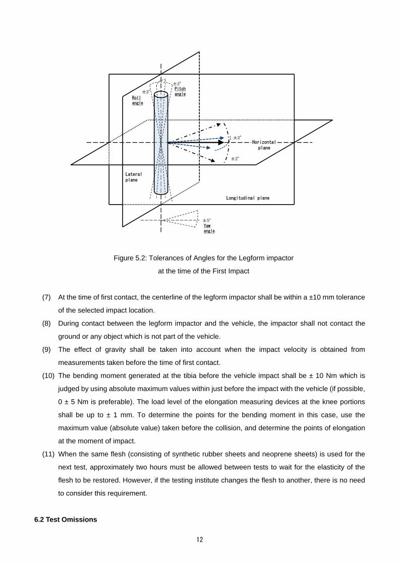
(2) The direction of the impact velocity vector shall be in the horizontal plane and parallel to the
longitudinal vertical plane of the vehicle. The tolerance for the direction of the velocity vector in the
horizontal plane and in the longitudinal plane shall be 0 ± 2° at the time of first contact. The axis of
the legform impactor shall be perpendicular to the horizontal plane, with a roll and pitch angle
tolerance of ± 2° in the lateral and longitudinal plane (if possible, 0 ± 1° is preferable). The horizontal,
longitudinal and lateral planes are orthogonal to each other (see Figure 5.2).
(3) The bottom of the legform impactor shall be at 75 mm above the ground reference plane at the time
of first contact with the bumper (see Figure 5.1), with a ±10 mm tolerance (if possible, a ±5 mm
tolerance is preferable).
Support
Ground level
Ground reference plane
Impactor in free flight
Ground reference plane= ground level
75 ± 10mm(at impact)
Figure 5.1: Impact Height of Legform impactor
(Complete vehicle in normal riding posture (left)
and or cut-body mounted on supports (right))
(4) The legform impactor for the bumper tests shall be in 'free flight' at the moment of impact. The
legform impactor shall be released to free flight at such a distance from the vehicle that the test
results are not influenced by contact of the legform impactor with the propulsion system during
rebound of the legform impactor.
(5) The legform impactor may be propelled by any means that can be shown to meet the requirements.
(6) At the time of first contact, the legform impactor shall have the intended orientation about its vertical
axis, for the correct operation of its knee joint, with a yaw angle tolerance of ±5° (see Figure 5.2).
12
Lateral plane
Longitudinal plane
Horizontal plane
±2°
±2°
±2°
±2°
±5°
Pitch angle
Roll angle
Yaw angle
Figure 5.2: Tolerances of Angles for the Legform impactor
at the time of the First Impact
(7) At the time of first contact, the centerline of the legform impactor shall be within a ±10 mm tolerance
of the selected impact location.
(8) During contact between the legform impactor and the vehicle, the impactor shall not contact the
ground or any object which is not part of the vehicle.
(9) The effect of gravity shall be taken into account when the impact velocity is obtained from
measurements taken before the time of first contact.
(10) The bending moment generated at the tibia before the vehicle impact shall be ± 10 Nm which is
judged by using absolute maximum values within just before the impact with the vehicle (if possible,
0 ± 5 Nm is preferable). The load level of the elongation measuring devices at the knee portions
shall be up to ± 1 mm. To determine the points for the bending moment in this case, use the
maximum value (absolute value) taken before the collision, and determine the points of elongation
at the moment of impact.
(11) When the same flesh (consisting of synthetic rubber sheets and neoprene sheets) is used for the
next test, approximately two hours must be allowed between tests to wait for the elasticity of the
flesh to be restored. However, if the testing institute changes the flesh to another, there is no need
to consider this requirement.
6.2 Test Omissions

13
If the selected collision points are symmetrical about the longitudinal vertical plane intersecting the
vehicle center and are assumed to have the same internal structure, it is possible to apply the test
results for one side to the other side.
6.3 Testing After the Side Collision Test
Collision points that might affect the results of the side collision test may be tested after the side collision
test. However, to be allowed to use this protocol, the vehicle manufacturer shall submit technical
documents to NASVA to explain the collision points that affect the side collision test results if the points
were tested before the side collision test.
6.4 Exchanging of Parts
A deformed or damaged part (e.g. bonnet, bumper, spoiler, headlight, etc.) must be replaced before
the next test, except those conducted at the locations specified below. Additionally, for exchanging parts
at the front of the vehicle, refer to Attachment 3.
(1) The collision point of the next test is more than 400 mm from the collision point of the preceding test.
(2) The deformed or damaged parts are unlikely to affect the next test result.
7. Recording and Measuring Items
7.1 Recording Prior to the Test
7.1.1 Confirming and Recording Received Vehicle for Test
After receiving a vehicle for the test, the testing institute shall check the following items and record the
results in the Appendix. At the same time, the test institute must make sure that the vehicle received
complies with specifications of the vehicle provided from NASVA.
(1) Name, model, and classification number or symbol of the vehicle
(2) Chassis number
(3) Shape of body
(4) Engine model
(5) Drive system
(6) Type of transmission
(7) Type of tires
7.1.2 Recording the Impactor Certification Results
(1) Characteristics of the legform impactor shall successfully pass the certification test specified in
Paragraph 1.7 of Attachment 2.
(2) The testing institute must record details of the legform impactor certification test in Appendix 5.
(3) If the flesh or main body of the legform impactor is damaged during the test and those parts are
then repaired, the repaired legform impactor must successfully pass the pendulum type dynamic
certification test specified in Paragraph 2 of Attachment 2.
7.1.3 Recording of Calibration Results of Measuring Instruments

14
(1) Results of the calibration conducted prior to the test, on the measuring instruments (measuring
channels used by the evaluation) shall be recorded. The calibration remains effective for one year
irrespective of how many times the instruments may be used during this period. However, if
abnormalities are observed, they must be recalibrated.
(2) Correctness of computation of the injury value shall be verified by using the calibration signal
generator, unless the calibration described in (1) was conducted not only for each channel including
transducers but also for the data acquisition system.
7.1.4 Recording of Final Vehicle Condition Prior to Test
After preparing the test vehicle according to the protocol described in Paragraph 3, the following items
shall be checked and recorded:
(1) Mass of the test vehicle
(2) Names and masses of the parts removed, and the mass after adjustment
(3) Heights of the vehicle (the points for measuring vehicle height shall be specified by the vehicle
manufacturer)
(4) Collision points
(5) Reference impact-measuring points
7.1.5 Recording of Test Room Temperature, etc.
Regarding the temperature conditions specified in 4.1.10, the following shall be recorded into Appendix
6:
(1) The test room temperature
(2) The duration during which the legform impactor was kept at the environment specified in Paragraph
4.1.10.
7.2 Recording During the Test
7.2.1 Recording Impact Velocity, Free Flight Posture of Legform Impactor, and Deviations from the
Target and Impact Points
(1) The velocity of the legform impactor just before the impact with the test vehicle shall be measured
using a velocity indicator, and the measured velocity shall be recorded.
(2) If the velocity indicator has any trouble in (1), the time differential of the moving distance of the legform
impactor just before impact in the high-speed photographing shall be adopted and recorded as an
equivalent to impact velocity.
(3) The legform impactor posture data during the free flight (from launch to the impact with the vehicle)
shall be recorded.
(4) If there was any problem in the measurement described in (3) above, NASVA and the vehicle
manufacturer shall discuss whether the test result can be used for assessing the collision point by
using (a) high-speed photographing data, (b) deviation of the actual collision point from the target
collision point, etc.
15
(5) Collision point deviation shall be determined and recorded by checking the positions of marks such
as paint left on the legform impactor prior to the test.
7.2.2 Recording of Electric Measurements
Electric measurements for injury assessment shall be recorded from -50 ms to 100 ms or longer.
Additionally, for monitoring purpose, it is recommended to record the bending moment at the femur,
elongation of the lateral collateral ligament (LCL) at the knee and acceleration at the knee (tibia side).
7.2.3 Recording the Maximum Values
By using the measured waveform data recorded as specified in Paragraph 7.2.2, the maximum values
of all measurement items shall be calculated and recorded.
7.2.4 High-Speed Photography
A high-speed VTR or the like shall be used as an auxiliary recording system in order to record the free
flight and impact posture of the legform impactor during the test.
7.3 Recording After the Test
7.3.1 Filming the Vehicle Condition Immediately After the Test
The test vehicle's following conditions shall be photographed:
(1) Damaged locations near the collision point
(2) Damaged internal parts within the collision point
7.3.2 Confirming and Recording the Damaged Parts
Check damages on the following parts of the test vehicle, and record the damages.
(1) The bonnet
(2) The front bumper (bumper face, grill, internal parts, etc.)
(3) The front body (the radiator support, etc.)
7.4 Management of Measured Values
The following rules apply to management of measured values:
(1) Measurement on the impact velocity (km/h) shall be recorded up to the first decimal place.
(2) Measurement on the posture angles (deg) of the legform impactor shall be recorded up to the first
decimal place.
(3) Measurement values shall be rounded at the first decimal place and recorded up to the next whole
number.
(4) Measurement value of LBRL height (mm) from the ground level shall be rounded at the first decimal
place and recorded up to the next whole number.
16
ATTACHMENT 1
Definition of Pushing Down Mode
1. Definition
If the test result matches the situation described below, pushing down mode is considered to have
occurred:
(i) The femur of the legform impactor leaned toward the ground hitting direction within 20 ms after the impact.
(ii) The femur of the legform impactor leaned toward the ground hitting direction before the maximum values
of (a) bending moment of tibia, (b) elongation of MCL and (c) elongation of ACL occurred.

17
ATTACHMENT 2
Specifications of Legform impactor and Requirements for Certification
1. Specifications of Legform impactor
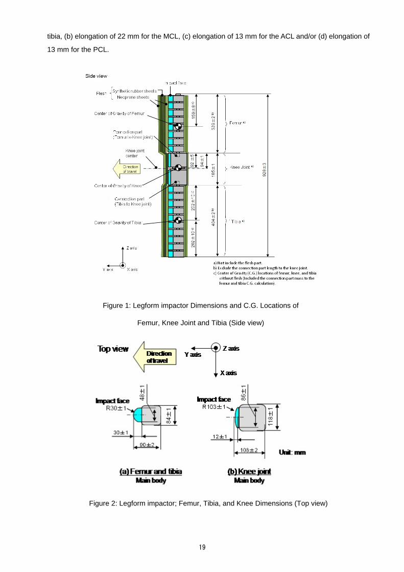
The legform impactor shall consist of flesh, flexible long bone segments (representing femur and tibia),
and a knee joint as shown in Figure 1. The overall length of the legform impactor shall be 928 ± 3 mm,
and its mass including flesh shall be 13.2 ± 0.7 kg. The length of the femur, knee joint, and tibia shall be
339 ± 2 mm, 185 ± 1 mm, and 404 ± 2 mm, respectively. The center position of the knee joint shall be
94 ± 1 mm from the top of the knee joint.
Brackets, pulleys, protectors, connection parts, etc. attached to the legform impactor for the purpose
of launching and/or protecting may extend beyond the dimensions shown in Figure 1.
1.1 The cross-sectional shape perpendicular to the Z-axis of the femur and tibia main bodies shall be 90 ±
2 mm in width along the Y-axis, and 84 ± 1 mm in width along the X-axis as shown in Figure 2. The
impact face shall be 30 ± 1 mm in radius, 30 ± 1 mm in width along the Y-axis, and 48 ± 1 mm in width
along the X-axis.
1.2 The cross-sectional shape perpendicular to the Z-axis of the knee joint shall be 108 ± 2 mm in width
along the Y-axis, and 118 ± 1 mm in width along the X-axis as shown in Figure 2. The impact face shall
be 103 ± 1 mm in radius, 12 ± 1 mm in width along the Y-axis, and 86 ± 1 mm in width along the X-axis.
1.3 The masses of the femur and tibia without flesh (including the connection part to the knee joint) shall be
2.46 ± 0.12 kg and 2.64 ± 0.13 kg respectively. The mass of the knee joint (without flesh) shall be 4.28
± 0.21 kg. The total mass of the femur, knee joint, and tibia shall be 9.38 ± 0.47 kg.
The center of gravity of the femur and tibia (without flesh, including the connection part to the knee
joint) shall be 159 ± 8 mm and 202 ± 10 mm respectively from the top (but not including the connection
part to the knee joint) of each part as shown in Figure 1.
The moment of inertia of the femur and tibia (without flesh, including the connection part inserted to
the knee joint) about the X-axis through the respective centers of gravity shall be 0.0325 ± 0.0016 kgm²
and 0.0467 ± 0.0023 kgm² respectively. The moment of inertia of the knee joint about the X-axis through
the respective center of gravity shall be 0.0180 ± 0.0009 kgm².
1.4 For each test, the legform impactor (femur, knee joint, and tibia) shall be covered by flesh composed of
synthetic rubber sheets (R1, R2) and neoprene sheets (N1F, N2F, N1T, N2T, N3) as shown in Figure 3.
The sheets are required to have a compression characteristic as shown in Figure 4. The compression
characteristic shall be checked using the same batch of sheets as those used for the legform impactor

18
flesh. The size of the sheets shall be within the requirements described in Figure 3.
1.5 The test legform impactor or at least the flesh shall be stored for at least four hours in a controlled storage
area with a stabilized temperature of 20 ± 2°C before removing the legform impactor for calibration.
After removal from the storage, the legform impactor shall not be subjected to conditions other than
those pertaining to the test area.
1.6 Legform impactor Instrumentation
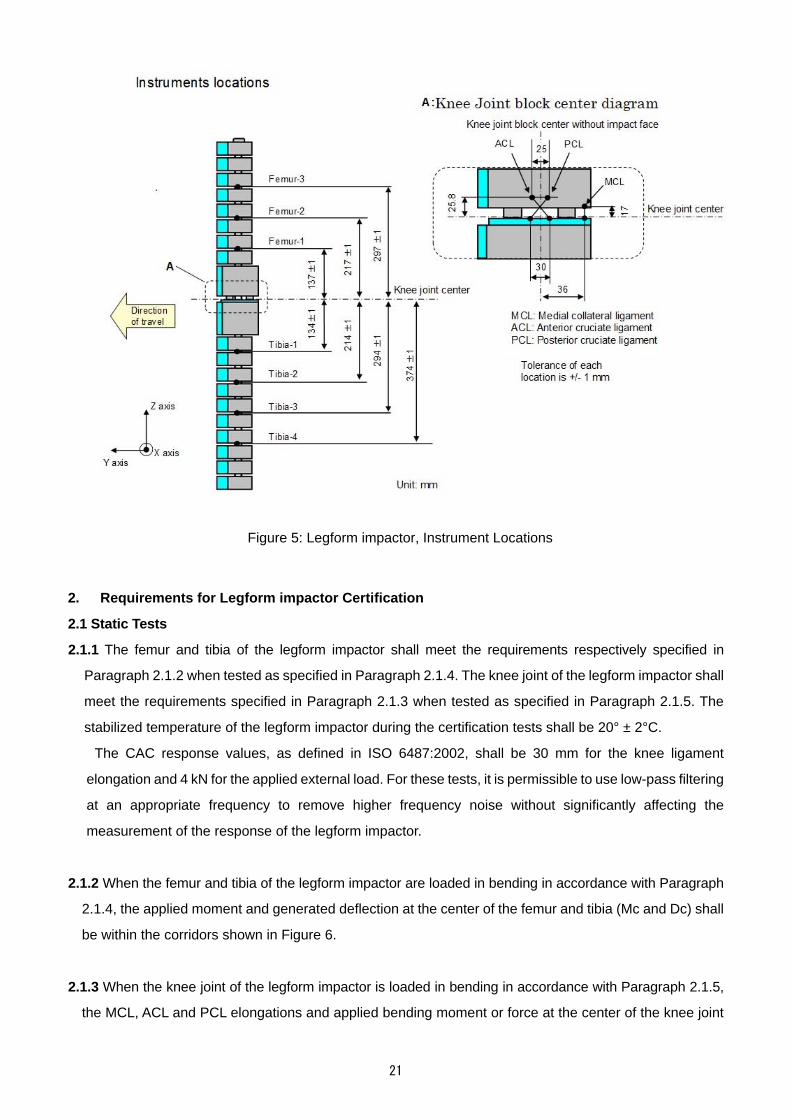
1.6.1 Four transducers shall be installed in the tibia to measure bending moments applied to the tibia. The
sensing locations of each of the transducers are as follows: tibia-1: 134 ± 1 mm, tibia-2: 214 ± 1 mm,
tibia-3: 294 ± 1 mm, and tibia-4: 374 ± 1 mm below the knee joint center respectively as shown in
Figure 5. The measurement axis of each transducer shall be the X-axis of the legform impactor.
1.6.2 Three transducers shall be installed in the knee joint to measure elongations of the MCL, ACL, and
PCL. The measurement locations of each transducer are shown in Figure 5. The measurement locations
shall be within ±4 mm along the X-axis from the knee joint center.
1.6.3 The instrumentation response value channel frequency class (CFC), as defined in ISO 6487:2002,
shall be 180 for all transducers. The CAC response values, as defined in ISO 6487:2002, shall be 30
mm for the knee ligament elongations and 400 Nm for the tibia bending moments. This does not require
that the legform impactor itself be able to physically elongate or bend until these values.
1.7 Legform impactor Certification
1.7.1 The legform impactor shall meet the performance requirements described in Paragraph 2. Certification
of the legform impactor shall be conducted at the timing described below.
1.7.1.1 It is permissible to use the legform impactor manufacturer's test data for the static certification tests
described in Paragraph 2.1 instead of the test institute conducting the test itself. However, if the legform
impactor does not meet the pendulum type dynamic certification test requirement described in
Paragraph 2.2 or the inverse type dynamic certification test requirement described in Paragraph 2.3,
the static test described in Paragraph 2.1 shall be conducted by the test institute or by the legform
impactor manufacturer.
1.7.1.2 The pendulum type dynamic certification test described in Paragraph 2.2 (and also the inverse type
dynamic certification test described in Paragraph 2.3 if necessary) shall be conducted just before the
series of tests of each vehicle. In addition, the pendulum type dynamic certification test (and also the
inverse type dynamic certification test if necessary) shall be conducted after replacing parts of the
legform impactor for repair, and when measured values exceed (a) bending moment of 380 Nm for the
19
tibia, (b) elongation of 22 mm for the MCL, (c) elongation of 13 mm for the ACL and/or (d) elongation of
13 mm for the PCL.
Figure 1: Legform impactor Dimensions and C.G. Locations of
Femur, Knee Joint and Tibia (Side view)
Figure 2: Legform impactor; Femur, Tibia, and Knee Dimensions (Top view)

20
Figure 3: Legform impactor Flesh Measurements
(a) Synthetic Rubber Sheets
(b) Neoprene Sheets
Figure 4: Legform impactor; Flesh Compression Characteristics
0
2
4
6
8
10
12
0 0.2 0.4 0.6 0.8 1
Strain
Str
ess
(M
Pa
)
Upper limit
Lower limit
0
1
2
3
4
5
6
0 0.2 0.4 0.6 0.8 1
Strain
Str
ess
(M
Pa
)
Upper Limit
Lower Limit
21
Figure 5: Legform impactor, Instrument Locations
2. Requirements for Legform impactor Certification
2.1 Static Tests
2.1.1 The femur and tibia of the legform impactor shall meet the requirements respectively specified in
Paragraph 2.1.2 when tested as specified in Paragraph 2.1.4. The knee joint of the legform impactor shall
meet the requirements specified in Paragraph 2.1.3 when tested as specified in Paragraph 2.1.5. The
stabilized temperature of the legform impactor during the certification tests shall be 20° ± 2°C.
The CAC response values, as defined in ISO 6487:2002, shall be 30 mm for the knee ligament
elongation and 4 kN for the applied external load. For these tests, it is permissible to use low-pass filtering
at an appropriate frequency to remove higher frequency noise without significantly affecting the
measurement of the response of the legform impactor.
2.1.2 When the femur and tibia of the legform impactor are loaded in bending in accordance with Paragraph
2.1.4, the applied moment and generated deflection at the center of the femur and tibia (Mc and Dc) shall
be within the corridors shown in Figure 6.
2.1.3 When the knee joint of the legform impactor is loaded in bending in accordance with Paragraph 2.1.5,
the MCL, ACL and PCL elongations and applied bending moment or force at the center of the knee joint

22
(Mc or Fc) shall be within the corridors shown in Figure 7.
2.1.4 The edges of the femur and tibia, not bending parts, shall be firmly mounted to the support rig as shown
in Figures 8 and 9. The Y-axis of the legform impactor shall be parallel to the loading axis within 180 ± 2°
tolerance. In order to avoid friction errors, roller plates shall be set underneath the support rigs.
The center of the loading force shall be applied at the center of the femur and tibia within ±2 mm
tolerance along the Z-axis. The force shall be increased at a rate between 10 and 100 mm/minute until
the bending moment at the center part (Mc) of the femur or tibia reaches 400 Nm.
2.1.5 The edges of the knee joint, not bending parts, shall be mounted to the support rig firmly as shown in
Figure 10. The Y-axis of the legform impactor shall be parallel to the loading axis within 180 ± 2°. In order
to avoid friction errors, roller plates shall be set underneath the support rigs. To avoid damage to the
legform impactor, a neoprene sheet shall be set underneath the loading ram, and the legform impactor
face of the knee joint shown in Figure 2 shall be removed. The neoprene sheet used in this test shall
have compression characteristics as shown in Figure 4.
The center of the loading force shall be applied at the center of the knee joint within ±2 mm tolerance
along the Z-axis. The external load shall be increased at a rate between 10 and 100 mm/minute until the
bending moment at the center part of the knee joint (Mc) reaches 400 Nm.
2.2 Pendulum Type Dynamic Certification Tests
2.2.1 The legform impactor (with the femur, knee joint and tibia firmly connected or assembled) shall meet
the requirements specified in Paragraph 2.2.3 when tested as specified in Paragraph 2.2.4.
2.2.2 General
2.2.2.1 The test facility used for the certification test shall have a stabilized temperature of 20 ± 2°C during
certification.
2.2.2.2 The temperature of the certification area shall be measured at the time of certification and
recorded in a certification report.
2.2.3 Requirements
2.2.3.1 When the legform impactor is used for a test as specified in Paragraph 2.2.4, the maximum bending
moment of the tibia at tibia-1 shall be 235–272 Nm, the maximum bending moment at tibia-2 shall be
187–219 Nm, the maximum bending moment at tibia-3 shall be 139–166 Nm, and the maximum bending
moment at tibia-4 shall be 90–111 Nm. The maximum elongation of the MCL shall be 20.5–26 mm, the
maximum elongation of the ACL shall be 8.0–10.5 mm, and the maximum elongation of the PCL shall be
3.5–5.0 mm.
For all these values, the readings used shall be from the initial impact timing to 200 ms after the impact
timing.
2.2.3.2 The instrumentation response value CFC, as defined in ISO 6487:2002, shall be 180 for all
23
transducers. The CAC response values, as defined in ISO 6487:2002, shall be 30 mm for the knee
ligament elongations and 400 Nm for the tibia bending moments. This does not require that the legform
impactor itself be able to physically elongate and bend to these values.
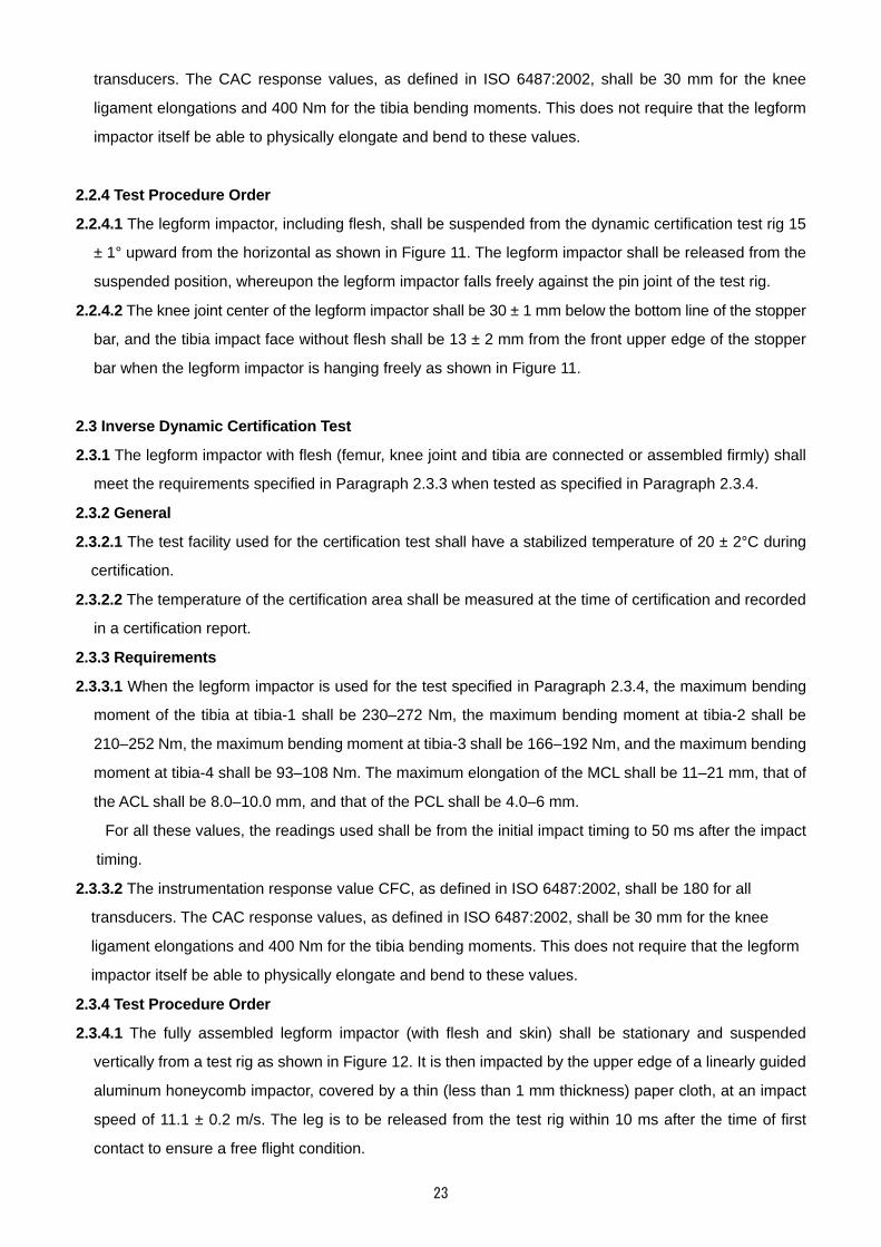
2.2.4 Test Procedure Order
2.2.4.1 The legform impactor, including flesh, shall be suspended from the dynamic certification test rig 15
± 1° upward from the horizontal as shown in Figure 11. The legform impactor shall be released from the
suspended position, whereupon the legform impactor falls freely against the pin joint of the test rig.
2.2.4.2 The knee joint center of the legform impactor shall be 30 ± 1 mm below the bottom line of the stopper
bar, and the tibia impact face without flesh shall be 13 ± 2 mm from the front upper edge of the stopper
bar when the legform impactor is hanging freely as shown in Figure 11.
2.3 Inverse Dynamic Certification Test
2.3.1 The legform impactor with flesh (femur, knee joint and tibia are connected or assembled firmly) shall
meet the requirements specified in Paragraph 2.3.3 when tested as specified in Paragraph 2.3.4.
2.3.2 General
2.3.2.1 The test facility used for the certification test shall have a stabilized temperature of 20 ± 2°C during
certification.
2.3.2.2 The temperature of the certification area shall be measured at the time of certification and recorded
in a certification report.
2.3.3 Requirements
2.3.3.1 When the legform impactor is used for the test specified in Paragraph 2.3.4, the maximum bending
moment of the tibia at tibia-1 shall be 230–272 Nm, the maximum bending moment at tibia-2 shall be
210–252 Nm, the maximum bending moment at tibia-3 shall be 166–192 Nm, and the maximum bending
moment at tibia-4 shall be 93–108 Nm. The maximum elongation of the MCL shall be 11–21 mm, that of
the ACL shall be 8.0–10.0 mm, and that of the PCL shall be 4.0–6 mm.
For all these values, the readings used shall be from the initial impact timing to 50 ms after the impact
timing.
2.3.3.2 The instrumentation response value CFC, as defined in ISO 6487:2002, shall be 180 for all
transducers. The CAC response values, as defined in ISO 6487:2002, shall be 30 mm for the knee
ligament elongations and 400 Nm for the tibia bending moments. This does not require that the legform
impactor itself be able to physically elongate and bend to these values.
2.3.4 Test Procedure Order
2.3.4.1 The fully assembled legform impactor (with flesh and skin) shall be stationary and suspended
vertically from a test rig as shown in Figure 12. It is then impacted by the upper edge of a linearly guided
aluminum honeycomb impactor, covered by a thin (less than 1 mm thickness) paper cloth, at an impact
speed of 11.1 ± 0.2 m/s. The leg is to be released from the test rig within 10 ms after the time of first
contact to ensure a free flight condition.

24
2.3.4.2 The aluminum 5052 honeycomb, which is attached in front of the moving ram, shall have a crush
strength of 75 psi ± 10% and 200 ± 5 mm in width, 160 ± 5 mm in length and 60 ± 2 mm in depth. To
ensure a consistent and good level of repeatability, the aluminum honeycomb should either have a 3/16-
inch cell size or a 1/4-inch cell size. The aluminum honeycomb should have a density of 2.0 pcf for a 3/16-
inch cell size or a density of 2.3 pcf for a 1/4-inch cell size.
2.3.4.3 The upper edge of the aluminum honeycomb face must coincide with the line of the rigid plate of the
linearly guided impactor. At the time of first contact, the tolerance range of the upper edge of the aluminum
honeycomb and the knee joint position line of the legform impactor with flesh shall be ± 2 mm. Additionally,
the honeycomb shall not be deformed before the impact test.
2.3.4.4 The legform impactor pitch angle (angle of rotation around the y-axis), i.e., the impact velocity vector
pitch angle, shall be within a margin of error of 0 ± 2° at the time of the initial collision. Similarly, the
legform impactor roll angle (angle of rotation around the z-axis), i.e., the impact velocity vector roll angle,
shall be within a margin of error of 0 ± 2° at the time of the initial collision. Additionally, the legform impactor
yaw angle (angle of rotation around the x-axis), i.e., the impact velocity vector yaw angle, shall be within
a margin of error of 0 ± 2° at the time of the initial collision.

25
(a) Femur bending corridor
(b) Tibia bending corridor
Figure 6: Legform impactor Requirement Corridor of Femur and Tibia in Static
Certification Test

26
Figure 7: Legform impactor Requirement Corridors for Knee Joint in Static
Certification Test

27
Figure 8: Legform impactor Test Set-up for Femur in Static Certification Test
Figure 9: Legform impactor Test Setup for Tibia in Static Certification Test

28
Figure 10: Legform impactor Test Setup for Knee Joint in Static Certification Test
Figure 11: Legform impactor Test Set-up for Pendulum Type Dynamic Legform impactor
Certification Test
Suspension angle
15 1 deg.
Released(Free fall around the pin joint)
Knee jointcenterline
Stopper bar
Pin joint
Additional Mass
13 2
10 deg.
30 1
Dynamic Certification Test Rig(Pendulum type)
Tibia
FemurKnee
FlexPLI with Flesh(cross sectional image)
Ø120 1
58 129.5 1
Additional MassMass: 5.0 kg ±0.05 (with screws)Inertia: 0.0061 ± 0.0006 kgm²
540 2
Center of gravity of additional mass
988.5 2
Dimension units: mm
Impactor side
R6 1

29
Figure 12: Legform impactor Test Set-up for Inverse Type Dynamic Legform impactor
Certification Test

30
ATTACHMENT 3
Detailed Protocols for Replacing Vehicle Parts
1. Repair of vehicle parts
Part Repair
Frame/Body These parts cannot be replaced even if they are deformed by the impact test.
Therefore, deformed parts shall be repaired to the original shape by using
several repair tools where possible.
Fender
Bonnet hinge
These parts take too long to replace. Therefore, deformed parts shall be
repaired to the original shape by using several repair tools where possible.
Other parts If other deformed parts would affect the subsequent test results, they shall be
repaired to the original shape by using several repair tools where possible.
2. Replacement of vehicle parts
Part Change Do Not Change
1. Bumper
2. Bonnet
3. Energy Absorber
If these parts were deformed
or broken by the preceding
test, they shall be changed to
new parts before the next
test.
If the collision point of the next test is located
400 mm or more from the collision point of
the preceding test.
1. Headlights If these parts were deformed
or broken by the preceding
test, they shall be changed to
new parts before the next
test.
If the collision point of the next test is located
in a symmetrical sub test area (e.g. L1 L3,
L3 L1) and the collision point of the next
test is located 400 mm or more from the
collision point of the preceding test.
1. Bumper Beam
2. Striker
3. Grill
4. Radiator Support
If these parts were deformed
or broken by the preceding
test, they shall be changed to
new parts before the next
test.
If the collision point of the next test is located
400 mm or more from the collision point of
the preceding test.
Other parts If the damaged or deformed
parts would affect the results
of the next test.

1
APPENDIX 1: SPECIFICATION DATA SHEET OF TEST VEHICLE
[For entry by the vehicle manufacturer and importer]
1. Specifications of test vehicle
Vehicle name, model, classification number or classification symbol
Chassis number
Body shape
Engine model
Drive system
Type of transmission
Type of tire
Tire air pressure Front: ____kPa, Rear: ______kPa
Fuel tank capacity L
2. Seat Adjustments
Driver's SeatFront
Passenger's Seat Other seats
Fore-aft adjustment of
seat (by seat-rail)
Adjustment distance per stage
mm mm mm
Total adjusted distance mm mm mm
Mid. posi-tion
from the front mm
( stages )mm
( stages) DesignStan-dard posi-tion
mm( stages)
from the rear mm
( stages )mm
( stages ) mm
( stages)
Fore-aft seat adjustment
(other)
Name of device Mid-position
Height adjustment device (only can adjust vertically)
Provided Not provided
Provided Not provided
Provided Not provided
Adjustment of seatback angle
Design standard angle deg
( stages )deg
( stages ) deg
( stages)
Other adjustment device
Name, Design standard position
Note) Enter the number of position adjusting stages counting the first locking position as 0
3. Reference Measuring Points of Vehicle Posture
(Enter the vehicle height after installing a mass of 75 kg to the driver and front passenger seat,
respectively, in addition to the mass of the test vehicle when brought in.)
(1) Height of front side
Reference point ( * ): Left Right
(2) Height of rear side

2
Reference point ( * ): Left Right
* Describe name of reference point. Submit drawings, if necessary to understand the point.
4. Reference: LBRL height (highest value) of vehicle scheduled for test
(1) LBRL height mm

3
APPENDIX 2: SPECIFICATION OF TEST VEHICLE
[For entry by the test institute]
1. Specifications of Test Vehicle
Vehicle name
Common name
Grade
Model type
Classification
Key optional equipment
Brand name and size of tire
Mass at vehicle delivery kg
2. Seat Adjustments
Driver's Seat Front
Passenger's seat Other seats
Fore-aft adjustment of
seat (by seat-rail)
Adjustment distance per stage
mm mm mm
Total adjusted distance
mm mm mm
Mid posi-tion
from the front end
mm( stages )
mm ( stages)
DesignStan-dard posi-tion
mm( stages)
from the rear end
mm( stages )
mm ( stages )
mm( stages)
Fore-aft seat adjustment
(other)
Name of device Mid-position
Height adjustment device (only can adjust vertically)
Provided Not provided
Provided Not provided
Provided Not provided
Adjustment of seatback angle
Design standard angle
deg
( stages )deg
( stages ) deg
( stages)
Other adjustment device
Name, Design standard
position
3. Other
Reference Measuring Points of Vehicle Posture
(1) Height of front side: Reference point ( * ): Left Right
(2) Height of rear side: Reference point ( * ): Left Right
* Describe name of reference point.

4
Appendix 2-1: Collision Points for Assessment (vehicle name: )
First candidate of collision point [NASVA]
Request x y z Impact parts and otherReplacement of bumper
and other
L1A
L1B
L2A
L2B
L3A
L3B
Note: 1."○" in the Area column [e.g.: L1A ] indicates 2nd candidates, without "○" indicates 1st candidates.
Remarks
L1
2. Reference impact point (x=0, y=0, z=0): Bonnet rear end on the vehicles's centerline.
L3
Impactorder
Area
L2
Distinction between 1st and2nd candidates
Impact point

5
Appendix 2-2: Bird's Eye Photo of Test Vehicle
Reference
・Test vehicle attached with marking
・Angle: 30 degrees in front of the test vehicle
・Photo taken using a digital camera
(use this photo for lower leg impactor test as well
as for head impactor test)

6
Appendix 2-3: Collision Points for Assessment (vehicle name: )
Second Candidate of Collision Point
Request x y z Impact parts and otherReplacement of bumper
and other
L1A
L1B
L2A
L2B
L3A
L3B
Note: 1."○" in the Area column [e.g.: L1A ] indicates 2nd candidates, without "○" indicates 1st candidates.
Remarks
L1
2. Reference impact point (x=0, y=0, z=0): Bonnet rear end on the vehicles's centerline.
L3
Impactorder
Area
L2
Distinction between 1st and2nd candidates
Impact point
7
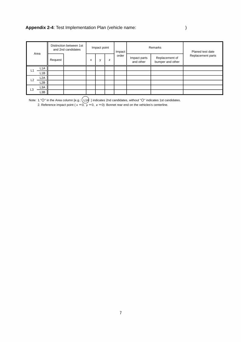
Appendix 2-4: Test Implementation Plan (vehicle name: )
Request x y zImpact parts
and otherReplacement of
bumper and other
L1A
L1B
L2A
L2B
L3A
L3B
Note: 1."○" in the Area column [e.g.: L1A ] indicates 2nd candidates, without "○" indicates 1st candidates.
Planed test dateReplacement parts
L1
2. Reference impact point (x=0, y=0, z=0): Bonnet rear end on the vehicles's centerline.
L3
Impactorder
Area
L2
Distinction between 1stand 2nd candidates
Impact point Remarks

8
Appendix 3-1: Specification Data Sheet of Test Vehicle
[For entry by the test institute]
1. Specifications of Test vehicle Vehicle name, Model, Classification number
Chassis number
Body shape
Engine model
Drive system
Type of transmission
Tire type
Tire air pressure Front wheel Right: Left:Rear wheel Right: Left:
Steer-ing
device
Shape of steering wheel
Air bag Not provided / Provided
Vertical adjustment Not provided / Provided (Electric, Manual)
Fore-aft adjustment Not Provided / Provided (Electric, Manual)
Seat
Fore-aft adjustment (seat-rail)
Dr. seat Not provided / Provided (Electric, Manual)
Fr. P. seat Not provided / Provided (Electric, Manual)
Other seat Not provided / Provided (Electric, Manual)
Fore-aft adjustment (other mechanism)
Dr. seat Device name :______, Not provided / Provided (Electric, Manual)
Fr. P. seat Device name :______, Not provided / Provided (Electric, Manual)
Other seat Device name :______, Not provided / Provided (Electric, Manual)
Height adjustment (only adjusted vertically)
Fr. P. seat Not provided / Provided (Electric, Manual)Other seat Not provided / Provided (Electric, Manual)Other seat Not provided / Provided (Electric, Manual)
Seatback adjustment Dr. seat Not provided / Provided (Electric, Manual)
Fr. P. seat Not provided / Provided (Electric, Manual)Other seat Not provided / Provided (Electric, Manual)
Other adjustment devices Dr. seat Device name:_________ (Electric, Manual)
Fr. P. seat Device name:_________ (Electric, Manual)Other seat Device name:_________ (Electric, Manual)
Fuel tank Capacity L
Reference Measuring Points of Vehicle Posture
(1) Height of front side
Reference point ( * ): Left Right
(2) Height of rear side
Reference point ( * ): Left Right
* Describe name of reference point.

9
Appendix 3-2: List of Test Results
Distinctionbetween 1st
and 2ndcandidates
Impactorder
Tibia-1(Nm)
Tibia-2(Nm)
Tibia-3(Nm)
Tibia-4(Nm)
MCL(mm)
ACL(mm)
PCL(mm)
Impactspeed(km/h)
Impactorposture
Deviation fromthe targetedimpact point
Remarks
L1A
L1B
L2A
L2B
L3A
L3B
L2
Area
L1
L3

10
Appendix 4: Results of Electric Measurements (area: sub area, sub-sub area)
Leg Impactor Measurement Items: (Tibia-1,Tibia-2,Tibia-3,Tibia-4)

11
Leg Impactor Measurement Items: (ACL, PCL, MCL, LCL*)
*Reference Measurements

12
Leg Impactor Measurement Items: (Femur-3*,Femur-2*,Femur-1*,Knee(tibia side)-Acc*)
*Reference Measurements

13
Appendix 5: Results of Leg Impactor Certification Test
Test
Number
Date/
Temperature
Calibration
Methods
Leg
Impactor
No.
Measurement
Items Maximum Value
***
Pendulum
or
Inverse
Tibia-1 Nm
Tibia-2 Nm
Tibia-3 Nm
Tibia-4 Nm
ACL mm
PCL mm
MCL mm
Test Result Pass Fail
Pendulum
or
Inverse
Tibia-1 Nm
Tibia-2 Nm
Tibia-3 Nm
Tibia-4 Nm
ACL mm
PCL mm
MCL mm
Test Result Pass Fail
Pendulum
or
Inverse
Tibia-1 Nm
Tibia-2 Nm
Tibia-3 Nm
Tibia-4 Nm
ACL mm
PCL mm
MCL mm
Test Result Pass Fail
Note: Attach wave forms during the calibration test.

14
Appendix 6: Temperature Records
Leg impactors soak start date and time:
/ / __/ :____
(Month/ Day/Year/ hour: minutes)
Temperature at the start of soak: Temperature: °C
Temperature when using leg impactor
Test No. Temperature (℃) Test Date/Time