Embed Size (px)
Citation preview

Special Applications – SPPP–2005 / 2006
SPECIAL APPLICATIONS iPAG
E
SNOWPLOW PREP PACKAGE (VYU)............................................................................................................................................. SP— 1
Ballast Compensating Weight .......................................................................................................................................... SP— 2
Chevrolet/GMC Snowplow Prep Package – Option VYU, Pickup – K15703-K25943 ......................................................... SP— 3
Chevrolet/GMC Snowplow Prep Package – Option VYU, Pickup – K25953-K35943 ......................................................... SP— 5
Chevrolet/GMC Snowplow Prep Package – Option VYU, Cab Chassis/Utility ................................................................... SP— 7
CMVSS 105 and FMVSS 105 Allowable Center of Gravity Calculation............................................................................... SP— 9
CMVSS 105 and FMVSS 105 Allowable Center of Gravity Charts ...................................................................................... SP— 11
CMVSS 135 and FMVSS 135 Allowable Center of Gravity Calculation............................................................................... SP— 12
CMVSS 135 and FMVSS 135 Allowable Center of Gravity Charts ...................................................................................... SP— 14
Snowplow Prep Package (VYU) Electrical Provisions .......................................................................................................... SP— 15
Figure 1 (Instrument Panel) ............................................................................................................................................ SP— 16
Figure 2 (Emergency Vehicle Roof Lamp Harness to Roof Header) ........................................................................... SP— 17
Figure 3 (Accessory Harness Grommet) ....................................................................................................................... SP— 18
Figure 4 (Forward Lamp Harness In-Line Connectors – L.H.) ..................................................................................... SP— 19
Figure 5 (Forward Lamp Harness In-Line Connectors – R.H.) ..................................................................................... SP— 20
Front Exterior Lamp Connector Circuit Function Charts ..................................................................................................... SP— 21
Forward Lamp Harness In-Line Connectors ........................................................................................................................ SP— 23
Headlamp Connectors ........................................................................................................................................................... SP— 24
Front Exterior Lamp Electrical Connector Part Numbers .................................................................................................... SP— 25
Figure 6 (Basic Trailer Wiring Package) ................................................................................................................................ SP— 26
Figure 7 (Heavy Duty Trailer Wiring Package) ....................................................................................................................... SP— 27

Special Applications – SPPP–2005 / 2006SNOWPLOW — ONLY ON THE C/K, UTILITY AND CAB CHASSIS
SPECIAL APPLICATIONS SP— 1PAG
E
SNOWPLOW PREP PACKAGE (VYU)
The chart on the following page shows GMTG approved models available with snowplow prep package-option VYU.
General Motors recommends that when a snowplow is mounted on a vehicle, only one passenger should accompany the driver. Morethan one passenger may exceed Front Gross Axle Weight Ratings.
Prior to installing a front mounted snowplow, the following process should be followed and necessary information obtained.
• Establish vehicle curb weight
• Establish chassis manufacturer’s front and rear axle weight ratings
• Chevrolet and GMC truck dealers can provide availability, specifications, Gross Vehicle Weight Ratings (GVWR), and Front andRear Gross Axle Weight Ratings (FGAWR/RGAWR). For vehicles already built, this information can be found on the certificationlabel installed on driver’s door/door frame or provided on the cover of the Incomplete Vehicle Document.
The following information should be obtained and provided by the manufacturers of snowplows and salt spreaders:
• Specifications, weights and center of gravity data
• Vehicle installation guidelines and instructions
• Calculation of weight distribution for the front and rear axles
The loaded vehicle with driver, passenger, aftermarket accessories, snowplows, spreader, and cargo must not exceed the Gross VehicleWeight Rating (GVWR), and Front and Rear Gross Axle Weight Ratings. In addition, the completed curb weight vehicle, with all installedaftermarket accessories, snowplow, and spreader, and with 400 lbs. for vehicles less than 10,000 lbs. and 500 lbs. for vehicles greaterthan 10,000 lbs. distributed in the driver-passenger area of the vehicle, must have a center of gravity location that is located within thetrapezoid formed by the coordinates A, B, C, D, H1 & H2, plus it must be to the rear of vertical line E and forward of vertical line F asdefined in the ALLOWABLE CENTER OF GRAVITY CHARTS. If the center of gravity location does not fall within the specified trapezoid,ballast weight may be required to shift the center of gravity location until it falls within the specified trapezoid.
The snowplow manufacturer and the installer of the aftermarket equipment should determine the amount of rear ballast required toensure that the vehicle, with the attached snowplow and aftermarket equipment, complies with the Allowable Center of Gravity Trapezoidand the resulting front and rear weight distribution ratio as defined in the Allowable Center of Gravity Charts published in this manual.
(Snowplow Prep Package — continued on next page)

Special Applications – SPPP–2005 / 2006SNOWPLOW — ONLY ON THE C/K, UTILITY AND CAB CHASSIS
SPECIAL APPLICATIONS SP— 2PAG
E
(Snowplow Prep Package — continued from previous page)
Ballast Compensating Weight
The use of rear ballast weight may be required to prevent exceeding the Gross Axle Weight Rating of the front axle. The use of rear ballastweight may be required to ensure that the center of gravity location of the completed vehicle, with the attached snowplow and otherinstalled equipment, complies with the Allowable Center of Gravity Trapezoid and the resulting front and rear weight distribution ratio,even though the actual front weight may be less than the Gross Axle Weight Rating of the front axle. In either case, the rearballast weight should be securely attached in the cargo box or behind the rear axle of the vehicle in a manner which prevents it frommoving during driving and stopping.
To help avoid personal injury, refer to Z-height setting procedurebefore adjusting torsion bars. If torsion bars are adjusted foraftermarket equipment, be sure to return them to specificationwhen the equipment is removed. Otherwise, a front shockabsorber may dislodge and damage a front brake line. This couldresult in an accident when minimum stopping distances arerequired.

Special Applications – SPPP–2005 / 2006SNOWPLOW — ONLY ON THE C/K, UTILITY AND CAB CHASSIS
SPECIAL APPLICATIONS SP— 3PAG
E
Chevrolet/GMC Snowplow Prep Package – Option VYU, Pickup – K15703-K25943
Model K15703 K15903 K25753 HD K25743 K25903 K25943
Cab Regular Regular Extended Crew Regular Crew
Wheelbase Inches 119 133 143.5 153 133 167
P.U. Box Length feet 6.5 8 6.5 6.5 8 8
GVWR lb. (option code) 6100(C5M) 6400(C7H) 9200(C6W) 9200(C6W) 9200(C6W) 9200(C6W)
GAWR lb. — Frt. 3925 3925 4800 4800 4800 4800
Engine Availability with VYU: Opt. CodeVortec 8.1L Gasoline V8 Engine L18 N/A N/A A N/A A N/A
Duramax 6.6L Diesel V8 Engine LLY N/A N/A A N/A A N/A
Vortec 4800 V8 Gasoline LR4 A A N/A N/A N/A N/A
Vortec 5300 V8 Gasoline LM7 A A N/A N/A N/A N/A
Vortec 6000 V8 Gasoline LQ4 N/A N/A A B B B
Base (B) Equipment Includes:Battery 600 CCA (*) — B B B B B B
Generator 160 amp. KW1 B B N/A N/A N/A N/A
Provisions for Rear Back-Up Lighting — B B B B B B
Front Tow Hooks V76 B B B B B B
Snowplow Prep Pkg. Includes: VYU
Upgrade Front Torsion Bar F60 X X X X X X
External Engine Oil Cooler LQ4 only KC4 N/A N/A R R R R
Generator 145-Amps KG3 N/A N/A X X X X
Provision for Roof Mntd. Emergency Light TRW X X X X X X
Transmission Cooler (air to oil) Auto only KNP X X X X X X
42mm Hole FOD with Rubber Grommet — X X X X X X(*) Trucks with LLY (Diesel Engine) come with dual 770 CCA batteries (TQ3) as base equipment B – base vehicle / A – available / X – included in package / Y – included where applicable / N/A – not available on this model / R – required on this mode
(continued on next page)

Special Applications – SPPP–2005 / 2006SNOWPLOW — ONLY ON THE C/K, UTILITY AND CAB CHASSIS
SPECIAL APPLICATIONS SP— 4PAG
E
Chevrolet/GMC Snowplow Prep Package – Option VYU, Pickup – K15703-K25943 (continued)
Model K15703 K15903 K25753 HD K25743 K25903 K25943
Cab Regular Regular Extended Crew Regular Crew
Wheelbase Inches 119 133 143.5 153 133 167
P.U. Box Length feet 6.5 8 6.5 6.5 8 8
GVWR lb. (option code) 6100(C5M) 6400(C7H) 9200(C6W) 9200(C6W) 9200(C6W) 9200(C6W)
GAWR lb. — Frt. 3925 3925 4800 4800 4800 4800
Snowplow Prep Pkg. Includes: (cont.) VYU
Fwd. Lamp Harness w/In-Line Connector — X X X X X X
Skid Plate “Off Road” NZZ X X X X X X
P265/70R17 ALS BW — B B N/A N/A N/A N/A
P265/70R17 ALS WOL — A A N/A N/A N/A N/A
LT 245/75R16E ALS/OOR TIRES (60 PSI) — N/A N/A R R R R
Suggested Optional Equipment:Locking Differential, Rear Axle G80 A A A A A A
Battery 770 CCA (*) 7Y9 A A A A A A
Batteries – 770 CCA & 600 CCA (*) 8B0 A A A A A A
Back-up Alarm – Gas Engine Only 8S3 A A A A A A
Engine Block Heater K05 A A A A A A
Replacement Floor Covering HD Rubber BG9 A A A A A A
Rear Window Defogger C49 A A A A A A(*) Trucks with LLY (Diesel Engine) come with dual 770 CCA batteries (TQ3) as base equipment B – base vehicle / A – available / X – included in package / Y – included where applicable / N/A – not available on this model / R – required on this model

Special Applications – SPPP–2005 / 2006SNOWPLOW — ONLY ON THE C/K, UTILITY AND CAB CHASSIS
SPECIAL APPLICATIONS SP— 5PAG
E
Chevrolet/GMC Snowplow Prep Package – Option VYU, Pickup – K25953-K35943
Model K25953 K35903 K35953 K35943 K35903 K35953 K35943
Cab Extended Regular Extended Crew Regular Extended Crew
Wheelbase Inches 157.5 133.0 157.5 167.0 133.0 157.5 167.0
P.U. Box Length feet 8 8 8 8 8 8 8
GVWR lb. (option code) 9200(C6W) 9900(C4M) 9900(C4M) 9900(C4M) 11400(C7W) 11400(C7W) 11400(C7W)
GAWR lb. — Frt. 4800 4800 4800 4800 4800 4800 4800
Engine Availability with VYU: Opt. CodeVortec 8.1L Gasoline V8 Engine L18 A A N/A N/A A A N/A
Duramax 6.6L Diesel V8 Engine LLY N/A N/A N/A N/A A N/A N/A
Vortec 6000 V8 Gasoline LQ4 B B B B B B B
Base (B) Equipment Includes:Battery 600 CCA (*) — B B B B B B B
Provisions for Rear Back-Up Lighting — B B B B B B B
Front Tow Hooks V76 B B B B B B B
Snowplow Prep Pkg. Includes: VYU
Upgrade Front Torsion Bar F60 X X X X X X X
External Engine Oil Cooler LQ4 only KC4 R R R R R R R
Generator 145-Amps KG3 X X X X X X X
Provision for Roof Mntd. Emergency Light TRW X X X X X X X
Transmission Cooler (air to oil) Auto only KNP X X X X X X X
42mm Hole FOD with Rubber Grommet — X X X X X X X
Fwd. Lamp Harness w/In-Line Connector — X X X X X X X(*) Trucks with LLY (Diesel Engine) come with dual 770 CCA batteries (TQ3) as base equipment B – base vehicle / A – available / X – included in package / Y – included where applicable / N/A – not available on this model / R – required on this mode
(continued on next page)

Special Applications – SPPP–2005 / 2006SNOWPLOW — ONLY ON THE C/K, UTILITY AND CAB CHASSIS
SPECIAL APPLICATIONS SP— 6PAG
E
Chevrolet/GMC Snowplow Prep Package – Option VYU, Pickup – K25953-K35943 (continued)
Model K25953 K35903 K35953 K35943 K35903 K35953 K35943
Cab Extended Regular Extended Crew Regular Extended Crew
Wheelbase Inches 157.5 133.0 157.5 167.0 133.0 157.5 167.0
P.U. Box Length feet 8 8 8 8 8 8 8
GVWR lb. (option code) 9200(C6W) 9900(C4M) 9900(C4M) 9900(C4M) 11400(C7W) 11400(C7W) 11400(C7W)
GAWR lb. — Frt. 4800 4800 4800 4800 4800 4800 4800
Snowplow Prep Pkg. Includes: (cont.) VYU
Skid Plate “Off Road” NZZ X X X X X X X
LT 245/75R16E ALS/OOR TIRES (60 PSI) — R N/A N/A N/A N/A N/A N/A
LT 265/75R16E — N/A R R R N/A N/A N/A
LT 215/85R16E ALS/OOR TIRES (70 PSI) — N/A R R R R R R
Suggested Optional Equipment:Locking Differential, Rear Axle G80 A — — — A A A
Battery 770 CCA (*) 7Y9 A A A A A A A
Batteries – 770 CCA & 600 CCA (*) 8B0 A A A N/A A A N/A
Back-up Alarm – Gas Engine Only 8S3 A A A A A A A
Engine Block Heater K05 A A A A A A A
Replacement Floor Covering HD Rubber BG9 A A A A A A A
Rear Window Defogger C49 A A A A A A A(*) Trucks with LLY (Diesel Engine) come with dual 770 CCA batteries (TQ3) as base equipment B – base vehicle / A – available / X – included in package / Y – included where applicable / N/A – not available on this model / R – required on this model

Special Applications – SPPP–2005 / 2006SNOWPLOW — ONLY ON THE C/K, UTILITY AND CAB CHASSIS
SPECIAL APPLICATIONS SP— 7PAG
E
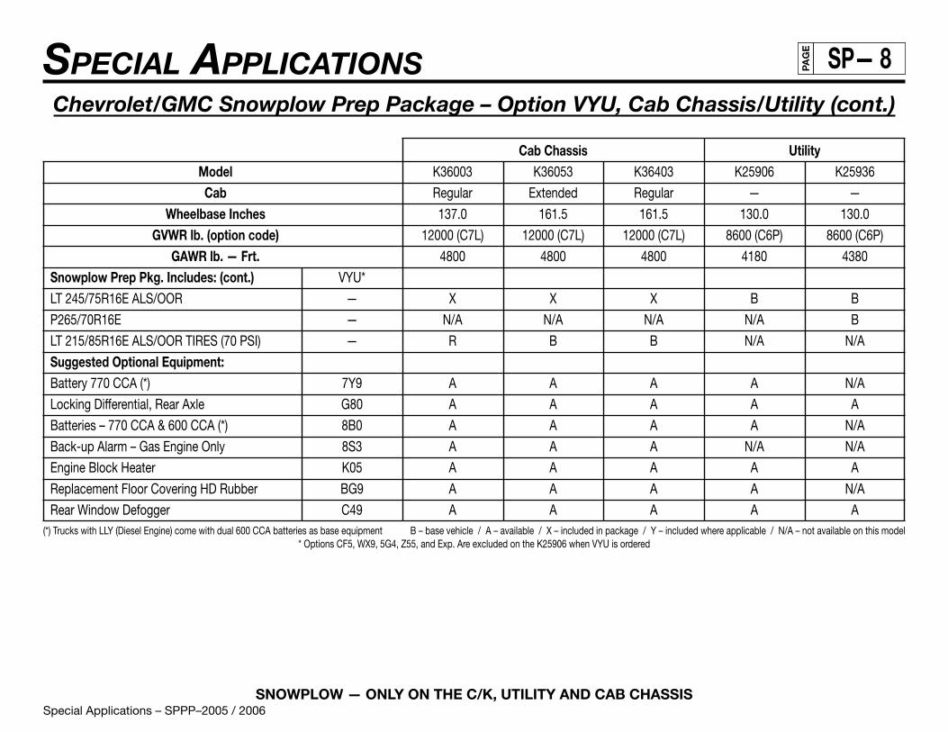
Chevrolet/GMC Snowplow Prep Package – Option VYU, Cab Chassis/Utility
Cab Chassis UtilityModel K36003 K36053 K36403 K25906 K25936
Cab Regular Extended Regular — —
Wheelbase Inches 137.0 161.5 161.5 130.0 130.0
GVWR lb. (option code) 12000 (C7L) 12000 (C7L) 12000 (C7L) 8600 (C6P) 8600 (C6P)
GAWR lb. — Frt. 4800 4800 4800 4180 4380
Engine Availability with VYU: Opt. CodeVortec 8.1L Gasoline V8 Engine L18 A A A N/A A
Duramax 6.6L Diesel V8 Engine LLY A N/A N/A N/A N/A
Vortec 6000 V8 Gasoline LQ4 B B B B N/A
Base (B) Equipment Includes:Battery 600 CCA (*) — B B B B B
Provisions for Rear Back-Up Lighting — B B B B B
Tow Hooks V76 B B B B B
Snowplow Prep Pkg. Includes: VYU*
Upgrade of front torsion bar F60 X X X X X
External Eng. Oil Cooler LQ4 only KC4 R R R R R
Generator 145-Amps KG3 X X X B X
Provision for Roof Mntd. Emergency Light TRW X X X X X
Transmission Cooler (air to oil) Auto only KNP X X X X X
42mm Hole FOD with Rubber Grommet — X X X X X
Fwd Lamp Harness with In-Line Connector — X X X X X
Skid Plate “Off Road” NZZ X X X A X(*) Trucks with LLY (Diesel Engine) come with dual 600 CCA batteries as base equipment B – base vehicle / A – available / X – included in package / Y – included where applicable / N/A – not available on this model
* Options CF5, WX9, 5G4, Z55, and Exp. Are excluded on the K25906 when VYU is ordered
(continued on next page)
Special Applications – SPPP–2005 / 2006SNOWPLOW — ONLY ON THE C/K, UTILITY AND CAB CHASSIS
SPECIAL APPLICATIONS SP— 8PAG
E
Chevrolet/GMC Snowplow Prep Package – Option VYU, Cab Chassis/Utility (cont.)
Cab Chassis UtilityModel K36003 K36053 K36403 K25906 K25936
Cab Regular Extended Regular — —
Wheelbase Inches 137.0 161.5 161.5 130.0 130.0
GVWR lb. (option code) 12000 (C7L) 12000 (C7L) 12000 (C7L) 8600 (C6P) 8600 (C6P)
GAWR lb. — Frt. 4800 4800 4800 4180 4380
Snowplow Prep Pkg. Includes: (cont.) VYU*
LT 245/75R16E ALS/OOR — X X X B B
P265/70R16E — N/A N/A N/A N/A B
LT 215/85R16E ALS/OOR TIRES (70 PSI) — R B B N/A N/A
Suggested Optional Equipment:Battery 770 CCA (*) 7Y9 A A A A N/A
Locking Differential, Rear Axle G80 A A A A A
Batteries – 770 CCA & 600 CCA (*) 8B0 A A A A N/A
Back-up Alarm – Gas Engine Only 8S3 A A A N/A N/A
Engine Block Heater K05 A A A A A
Replacement Floor Covering HD Rubber BG9 A A A A N/A
Rear Window Defogger C49 A A A A A(*) Trucks with LLY (Diesel Engine) come with dual 600 CCA batteries as base equipment B – base vehicle / A – available / X – included in package / Y – included where applicable / N/A – not available on this model
* Options CF5, WX9, 5G4, Z55, and Exp. Are excluded on the K25906 when VYU is ordered

Special Applications – SPPP–2005 / 2006SNOWPLOW — ONLY ON THE C/K, UTILITY AND CAB CHASSIS
SPECIAL APPLICATIONS SP— 9PAG
E
CMVSS105 and FMVSS105 Allowable Center of Gravity Calculation
C/G of vehicle in CMVSS or FMVSS unladen condition [Curb + 181.4 kg. (400 lb) or Curb + 226.8 kg. (500 lb) as defined by CMVSS 105and FMVSS 105] must be inside shaded area – that is, the C/G must be within the trapezoid formed by the coordinates A, B, C, D, H1,& H2, plus the C/G must be to the rear of vertical line E and forward of vertical line F.
The center of gravity of the total vehicle falls within the areas referenced on the “ALLOWABLE CENTER OF GRAVITY CHART” that follows.Instructions for determining the allowable center of gravity variation are listed below:
These charts detail the envelope of allowable center of gravity variation for completed vehicles. This is significant for the lightly loadedportion of FMVSS 105, which is defined as curb plus 181.4 kg (400 lb) distributed in the driver-passenger area of the vehicle for vehicles withGVWR of 4536 kg (10,000 lb) or less or as curb plus 226.8 kg (500 lb) distributed in the driver-passenger area of the vehicle for vehicles withGVWR greater than 4536 kg (10,000 lb).
The lightly loaded center of gravity complete vehicles needs to be restricted so it will meet FMVSS 105 stopping distances. The laden centerof gravity does not need to be specified as it is controlled within the CMVSS 105 and FMVSS 105 test procedure by specific instructions asto how ballast is to be placed (while height is not controlled, it is assumed that for test purposes it would be reasonable).
For Body Builder’s use, the center of gravity location can be approximated by the following formula:
d = [Wrc + Wrb + [(Hp)(Wp)/WB]] WBWt
h = [h1Wc + h2Wb + (h3)(Wp)]Wt
d = horizontal distance from front wheels to completed vehicle center of gravity cm (in)
(continued on next page)

Special Applications – SPPP–2005 / 2006SNOWPLOW — ONLY ON THE C/K, UTILITY AND CAB CHASSIS
SPECIAL APPLICATIONS SP— 10PAG
E
CMVSS 105 and FMVSS 105 Allowable Center of Gravity Calculation (continued)
h = vertical distance from ground to completed vehicle center of gravity cm (in)Wrc = rear component of bare chassis weight kg (lb)
Wrb = rear component of body weight kg (lb)WB = vehicle wheelbase cm (in)Wt = total weight of chassis and body kg (lbs) plus 181.4 kg (400 lb) for vehicles with GVWR of 4536 kg (10,000 lb) or lessWt = total weight of chassis and body kg (lbs) plus 226.8 kg (500 lb) for vehicles with GVWR greater than 4536 kg (10,000 lb)
h1 = center of gravity height from ground of the bare chassis = 71.1 cm (28 in)Wc = total weight of chassis kg (lb)h2 = center of gravity height of body from ground cm (in)
Wb = total weight of body kg (lb)
Wp = 181.4 kg (400 lb) amount from lightly loaded definition that is evenly distributed in driver-passenger area ofvehicle for vehicles with GVWR of 4536 kg (10,000 lb) or less
Wp = 226.8 kg (500 lb) amount from lightly loaded definition that is evenly distributed in driver-passenger area ofvehicle for vehicles with GVWR greater than 4536 kg (10,000 lb)
Hp = 146.7 cm (57.76 in) horizontal distance from front axle to center of gravity of 181.4 kg (400 lb) or226.8 kb (500 lb) evenly distributed in driver-passenger area of vehicle
h3 = 94.8 cm (37.32 in) vertical center of gravity height of 181.4 kg (400 lb) evenly distributed in driver-passengerarea for vehicles with 3900 kg (8600 lb) GVWR
h3 = 99.9 cm (39.33 in) vertical center of gravity height of 181.4 kg (400 lb) evenly distributed in driver-passengerarea for vehicles with 3856, 4173 and 4491 kg (8500, 9200 and 9900 lb) GVWR
h3 = 99.9 cm (39.33 in) vertical center of gravity height of 226.8 kg (500 lb) evenly distributed in driver-passengerarea for vehicles with 5171 - 5443 kg (11,400 - 12,000 lb) GVWR
NOTE: An alternate method of center of gravity calculation may be found in the current issue of the General Motors Body BuildersBook in the general instruction section and in SVIE Bulletin #39.

Special Applications – SPPP–2005 / 2006SNOWPLOW — ONLY ON THE C/K, UTILITY AND CAB CHASSIS
SPECIAL APPLICATIONS SP— 11PAG
E
CMVSS105 and FMVSS105 Allowable Center of Gravity Charts
Snowplow Prep Package VehiclesCoordinates of Allowable C/G Variation at CMVSS/FMVSS Unladen Curb Wt. + Forward Rearward
181.4 kg (400 lbs.) or 226.8 kg (500 lbs.) as defined by CMVSS & FMVSS 105 C/G Limit C/G Limit
Model GVWR Brake Wheelbase Rear H1 cm (in) H2 cm (in) A cm (in) B cm (in) C cm (in) D cm (in) E cm (in) F cm (in)Kg (lb) System cm (in) WheelK25906 3901 (8600) JH6 330.2 (130) SRW 30.5 (12) 121.9 (48) 129.5 (51) 198.1 (78) 205.7 (81) 264.2 (104) 129.5 (51) 259.1 (102)K25936 3901 (8600) JH6 330.2 (130) SRW 30.5 (12) 121.9 (48) 129.5 (51) 198.1 (78) 205.7 (81) 264.2 (104) 129.5 (51) 259.1 (102)K25903 4173 (9200) JH6 337.82 (133) SRW 30.5 (12) 121.9 (48) 91.4 (36) 160.0 (63) 205.7 (81) 269.23 (106) 127.0 (50) 269.23 (106)K25753 4173 (9200) JH6 364.49 (143.5) SRW 30.5 (12) 121.9 (48) 96.5 (38) 165.1 (65) 218.4 (86) 284.5 (112) 137.2 (54) 284.5 (112)K25743 4173 (9200) JH6 388.62 (153) SRW 30.5 (12) 121.9 (48) 101.6 (40) 170.2 (67) 231.1 (91) 297.2 (117) 144.8 (57) 297.2 (117)K25953 4173 (9200) JH6 400.05 (157.5) SRW 30.5 (12) 121.9 (48) 104.1 (41) 172.7 (68) 238.8 (94) 304.8 (120) 147.3 (58) 304.8 (120)K25943 4173 (9200) JH6 424.18 (167) SRW 30.5 (12) 121.9 (48) 109.2 (43) 177.8 (70) 251.5 (99) 317.5 (125) 157.5 (62) 317.5 (125)K35903 4491 (9900) JH6 337.82 (133) SRW 30.5 (12) 121.9 (48) 109.2 (43) 167.6 (66) 162.6 (64) 221.0 (87) 157.5 (62) 221.0 (87)K35953 4491 (9900) JH6 400.05 (157.5) SRW 30.5 (12) 121.9 (48) 127.0 (50) 185.4 (73) 182.9 (72) 243.8 (96) 137.2 (54) 243.8 (96)K35943 4491 (9900) JH6 424.18 (167) SRW 30.5 (12) 121.9 (48) 132.1 (52) 190.5 (75) 193.0 (76) 254.0 (100) 144.8 (57) 254.0 (100)K35903 5171 (11400) JH7 337.82 (133) DRW 30.5 (12) 121.9 (48) 111.8 (44) 157.5 (62) 256.5 (101) 276.9 (109) 111.8 (44) 276.9 (109)K35953 5171 (11400) JH7 400.05 (157.5) DRW 30.5 (12) 121.9 (48) 129.5 (51) 175.3 (69) 302.3 (119) 324.9 (128) 129.5 (51) 324.9 (128)K35943 5171 (11400) JH7 424.18 (167) DRW 30.5 (12) 121.9 (48) 137.2 (54) 182.9 (72) 319.8 (126) 342.9 (135) 137.2 (54) 342.9 (135)K36003 5443 (12000) JH7 348.0 (137) DRW 30.5 (12) 121.9 (48) 116.8 (46) 160.0 (63) 264.2 (104) 284.5 (112) 116.8 (46) 284.5 (112)K36053 5443 (12000) JH7 410.2 (161.5) DRW 30.5 (12) 121.9 (48) 134.6 (53) 177.8 (70) 309.9 (122) 332.5 (131) 134.6 (53) 332.5 (131)K36403 5443 (12000) JH7 410.2 (161.5) DRW 30.5 (12) 121.9 (48) 134.6 (53) 177.8 (70) 309.9 (122) 332.5 (131) 134.6 (53) 332.5 (131)
SRW = Single Rear Wheel Brake Systems:DRW = Dual Rear Wheel Vacuum Powered Boosters JF7C/G = Center of Gravity Hydraulic Powered Boosters JH6, JH7

Special Applications – SPPP–2005 / 2006SNOWPLOW — ONLY ON THE C/K, UTILITY AND CAB CHASSIS
SPECIAL APPLICATIONS SP— 12PAG
E
CMVSS135 and FMVSS135 Allowable Center of Gravity Calculation
C/G of vehicle in CMVSS or FMVSS unladen condition [Curb + 181.4 kg. (400 lb)] must be inside shaded area – that is, the C/G mustbe within the trapezoid formed by the coordinates A, B, C, D, H1, & H2, plus the C/G must be to the rear of vertical line E and forwardof vertical line F.
The center of gravity of the total vehicle falls within the areas referenced on the “ALLOWABLE CENTER OF GRAVITY CHART” that follows.Instructions for determining the allowable center of gravity variation are listed below:
These charts detail the envelope of allowable center of gravity variation for completed vehicles. This is significant for the lightly loadedportion of CMVSS 135 and FMVSS 135, which is defined as curb plus 181.4 kg (400 lb) distributed in the driver-passenger area of the vehicle.
The lightly loaded center of gravity complete vehicles needs to be restricted so it will meet CMVSS 135 and FMVSS 135 stopping distances.The laden center of gravity does not need to be specified as it is controlled within the CMVSS 135 and FMVSS 135 test procedure by specificinstructions as to how ballast is to be placed (while height is not controlled, it is assumed that for test purposes it would be reasonable).
For Body Builder’s use, the center of gravity location can be approximated by the following formula:
d = [Wrc + Wrb + [(Hp)(Wp)/WB]] WBWt
h = [h1Wc + h2Wb + (h3)(Wp)]Wt
d = horizontal distance from front wheels to completed vehicle center of gravity cm (in)h = vertical distance from ground to completed vehicle center of gravity cm (in)
Wrc = rear component of bare chassis weight kg (lb) Wrb = rear component of body weight kg (lb)
(continued on next page)

Special Applications – SPPP–2005 / 2006SNOWPLOW — ONLY ON THE C/K, UTILITY AND CAB CHASSIS
SPECIAL APPLICATIONS SP— 13PAG
E
CMVSS135 and FMVSS135 Allowable Center of Gravity Calculation (continued)
WB = vehicle wheelbase cm (in)Wt = total weight of chassis and body kg (lbs) plus 181.4 kg (400 lb)
h1 = center of gravity height from ground of the bare chassis = 71.1 cm (28 in)Wc = total weight of chassis kg (lb)h2 = center of gravity height of body from ground cm (in)
Wb = total weight of body kg (lb)Wp = 181.4 kg (400 lb) amount from lightly loaded definition that is evenly distributed in driver-passenger area of vehicle
Hp = 146.7 cm (57.76 in) horizontal distance from front axle to center of gravity of 181.4 kg (400 lb) evenly distributed indriver-passenger area of vehicle
h3 = 94.8 cm (37.72 in) vertical center of gravity height of 181.4 kg (400 lb) evenly distributed in driver-passengerarea for vehicles with 3500 kg (7716 lb) GVWR or less
NOTE: An alternate method of center of gravity calculation may be found in the current issue of the General Motors Body BuildersBook in the general instruction section and in SVIE Bulletin #39.

Special Applications – SPPP–2005 / 2006SNOWPLOW — ONLY ON THE C/K, UTILITY AND CAB CHASSIS
SPECIAL APPLICATIONS SP— 14PAG
E
CMVSS135 and FMVSS135 Allowable Center of Gravity Charts
Snowplow Prep Package VehiclesCoordinates of Allowable C/G Variation at CMVSS/FMVSS Unladen Curb Wt. + Forward Rearward
181.4 kg (400 lbs.) or 226.8 kg (500 lbs.) as defined by CMVSS & FMVSS 105 C/G Limit C/G Limit
Model GVWR Brake Wheelbase Rear H1 cm (in) H2 cm (in) A cm (in) B cm (in) C cm (in) D cm (in) E cm (in) F cm (in)Kg (lb) System cm (in) WheelK15703 2903 (6400) JF7 302.26 (119) SRW 30.5 (12) 121.9 (48) 104.1 (41) 144.8 (57) 134.6 (53) 203.2 (80) 104.1 (41) 203.2 (80)K15903 2903 (6400) JF7 337.82 (133) SRW 30.5 (12) 121.9 (48) 114.3 (45) 152.4 (60) 152.4 (60) 221.0 (87) 114.3 (45) 221.0 (87)
SRW = Single Rear Wheel Brake Systems:DRW = Dual Rear Wheel Vacuum Powered Boosters JF7C/G = Center of Gravity Hydraulic Powered Boosters JH6, JH7

Special Applications – SPPP–2005 / 2006SNOWPLOW — ONLY ON THE C/K, UTILITY AND CAB CHASSIS
SPECIAL APPLICATIONS SP— 15PAG
E
Snowplow Prep Package (VYU) Electrical Provisions
Emergency Roof-Mounted Lamp Switch This provision includes a dash-mounted switch (see Figure 1), a relay, and wiring which is routedup along the Left Hand B pillar that terminates at the roof as coiled blunt cut wires (see Figure 2). There are two blunt cut 12-gauge (3.0 mm2)wires, one is Brown (roof-mounted lamp power), it is controlled by the dash-mounted switch through the relay, the other is Black (ground).The Brown power wire is protected by the 30-Amp SEO 2 fuse which is located in the Underhood Electrical Center.
145-Amp Generator The 145-Amp generator – Option KG3, will be equipped on all Full Size K2500/3500 Series pickups, cab chassis andutilities with Snow Plow Prep Package – Option VYU, which is an upgrade from the standard 105-Amp generator.
160-Amp Generator The 160-Amp generator – Option KW1, will be equipped on all Full Size K1500 Series Pickups with Snow Plow PrepPackage – Option VYU, which is an upgrade from the standard 145-Amp generator – Option KG3.
Accessory Harness Grommet Trucks will come equipped with a predrilled 42mm pass-through hole located on the dash panel on the lefthand side of the vehicle. The hole will be sealed with a grommet (see Figure 3) which can be used by the upfitter for pass-through wiring. Touse the grommet (part# 15336702), the upfitter slices off the tape tab end (in engine compartment) of the grommet and then spreads it opento pass wiring through.
Forward Lamp Harness In-Line Connector The forward lamp wiring harness will have a set of mating eight cavity connectors on both theleft and right hand side of the vehicle (see Figures 4 & 5). The upfitter will be able to disconnect the in-line connectors which will allowinterfacing with the forward lamp circuits (Front Parklamp, Turn Signal and DRL). The headlamp circuits must be accessed from the headlampconnectors. Circuit function charts of these connectors are on page 10. Connector face diagrams of the connectors are on pages 11 and 12.A parts list of these connectors is provided on page 13.
Backup Lamp Power Feed Although this feature is standard on the All New C/K pickup trucks, it should be pointed out that a backup lamppower feed is provided at the rear of the vehicle through the trailer wiring harness. This circuit is protected by the 10-Amp TRLRB/U fuse which is located in the Underhood Electrical Center. On vehicles with Light Duty Trailer Wiring (see Figure 6) which comes standard,this circuit can be accessed through the Light Green trailer wire. This wire is blunt cut and located at the rear of the vehicle along with othertrailer tow circuits. On vehicles with Heavy Duty Trailer Wiring option (see Figure 7), this circuit is located in pin A of the trailer in-lineconnector at the rear of the vehicle.

SNOWPLOW — ONLY ON THE C/K, UTILITY AND CAB CHASSIS
SPECIAL APPLICATIONS SP— 16PAG
E
Special Applications – SPPP–2005 / 2006
Figure 1

SNOWPLOW — ONLY ON THE C/K, UTILITY AND CAB CHASSIS
SPECIAL APPLICATIONS SP— 17PAG
E
Special Applications – SPPP–2005 / 2006
Figure 2

SNOWPLOW — ONLY ON THE C/K, UTILITY AND CAB CHASSIS
SPECIAL APPLICATIONS SP— 18PAG
E
Special Applications – SPPP–2005 / 2006
Figure 3

SNOWPLOW — ONLY ON THE C/K, UTILITY AND CAB CHASSIS
SPECIAL APPLICATIONS SP— 19PAG
E
Special Applications – SPPP–2005 / 2006
Figure 4

SNOWPLOW — ONLY ON THE C/K, UTILITY AND CAB CHASSIS
SPECIAL APPLICATIONS SP— 20PAG
E
Special Applications – SPPP–2005 / 2006
Figure 5

Special Applications – SPPP–2005 / 2006SNOWPLOW — ONLY ON THE C/K, UTILITY AND CAB CHASSIS
SPECIAL APPLICATIONS SP— 21PAG
E
Front Exterior Lamp Connector Circuit Function Charts
LH Forward Lamp Harness In-Line ConnectorsCavity Circuit Wire Color Function Fuse
A 2309 BRN Front Parklamp 10-Amp FR PARK
B 2309 BRN Front Parklamp 10-Amp FR PARK
C 2114 LT BLU Turn Signal – Left In-line w/LF Side Marker
D — — — —
E 2114 LT BLU Turn Signal – Left 10-Amp LT TURN
F 150 BLK Pk/Turn to Gnd —
G 545 DK BLU DRL 10-Amp DRL
H 150 BLK DRL to Gnd —
RH Forward Lamp Harness In-Line ConnectorsCavity Circuit Wire Color Function Fuse
A 2309 BRN Front Parklamp 10-Amp FR PARK
B 2309 BRN Front Parklamp 10-Amp FR PARK
C 2115 DK BLU Turn Signal – Right In-line w/RT Side Marker
D –– –– –– ––
E 2115 DK BLU Turn Signal – Right 10-Amp RT TURN
F 150 BLK Pk/Turn to Gnd ––
G 545 DK BLU DRL 10-Amp DRL
H 150 BLK DRL to Gnd ––
NOTE: All fuses referenced above are located in the Underhood Electrical Center.
(continued on next page)

Special Applications – SPPP–2005 / 2006 — Revised 02/2006SNOWPLOW — ONLY ON THE C/K, UTILITY AND CAB CHASSIS
SPECIAL APPLICATIONS SP— 22PA
GE
Front Exterior Lamp Connector Circuit Function Charts (continued)
LH Low Beam ConnectorCavity Circuit Wire Color Function Fuse
A 712 YEL Left Low Beam 10-Amp #52 LO HDLP-LT
B 550 BLK Ground ———
RH Low Beam ConnectorCavity Circuit Wire Color Function Fuse
A 312 TAN/WHT Right Low Beam 10-Amp #55 LO HDLP-RT
B 150 BLK Ground ———
LH High Beam ConnectorCavity Circuit Wire Color Function Fuse
A 711 DK GRN/WHT Left High Beam 10-Amp #59 HI HDLP-LT
B 550 BLK Ground ———
RH High Beam ConnectorCavity Circuit Wire Color Function Fuse
A 311 LT GRN/BLK Right High Beam 10-Amp #46 HI HDLP-RT
B 150 BLK Ground ———
NOTE: All fuses referenced above are located in the Underhood Electrical Center.

SNOWPLOW — ONLY ON THE C/K, UTILITY AND CAB CHASSIS
SPECIAL APPLICATIONS SP— 23PAG
E
Special Applications – SPPP–2005 / 2006
Forward Lamp Harness In-Line Connectors

SNOWPLOW — ONLY ON THE C/K, UTILITY AND CAB CHASSIS
SPECIAL APPLICATIONS SP— 24PAG
E
Special Applications – SPPP–2005 / 2006
Headlamp Connectors

Special Applications – SPPP–2005 / 2006SNOWPLOW — ONLY ON THE C/K, UTILITY AND CAB CHASSIS
SPECIAL APPLICATIONS SP— 25PAG
E
Front Exterior Lamp Electrical Connector Part Numbers
Part # Connector12047938 FORWARD LAMP IN-LINE HARNESS CONNECTOR (F)
12047933 FORWARD LAMP IN-LINE HARNESS CONNECTOR (M)
12059181 LOW BEAM CONNECTOR (F) (ON VEHICLE)
12084166 LOW BEAM CONNECTOR (M)
12059183 HIGH BEAM CONNECTOR (F) (ON VEHICLE)
12084167 HIGH BEAM CONNECTOR (M)
NOTE: Terminals and secondary locks may have to be ordered separately. Further details regarding the connectors can be obtained fromthe Delphi Products Handbooks or by calling 1-800-PACKARD (1-800-722-5273).

SNOWPLOW — ONLY ON THE C/K, UTILITY AND CAB CHASSIS
SPECIAL APPLICATIONS SP— 26PAG
E
Special Applications – SPPP–2005 / 2006
Figure 6

SNOWPLOW — ONLY ON THE C/K, UTILITY AND CAB CHASSIS
SPECIAL APPLICATIONS SP— 27PAG
E
Special Applications – SPPP–2005 / 2006
Figure 7