Embed Size (px)
DESCRIPTION
Single Phase Sampler Manual
Citation preview

Proserv 4 Greenbank Place East Tullos Aberdeen
AB12 3BT
Tel: +44 (0) 1224 87 18 00 Fax: +44 (0) 1224 89 60 90 Email: [email protected] www.proserv.com
Registered Address: 70 Queens Road, Aberdeen, AB15 4YE
Proserv UK Ltd 1 Registered in Scotland No 122029
Operations Manual for the
Proserv Mark II Model Positive Displacement Sampler
Including the Single Phase System

Proserv 4 Greenbank Place East Tullos Aberdeen
AB12 3BT
Tel: +44 (0) 1224 87 18 00 Fax: +44 (0) 1224 89 60 90 Email: [email protected] www.proserv.com
Registered Address: 70 Queens Road, Aberdeen, AB15 4YE
Proserv UK Ltd 2 Registered in Scotland No 122029
Contents CONTENTS .......................................................................................................................................................... 2
LIST OF TABLES ................................................................................................................................................. 5
LIST OF FIGURES ............................................................................................................................................... 6
ACKNOWLEDGEMENTS ..................................................................................................................................... 9
ABOUT THIS MANUAL ........................................................................................................................................ 9 ABBREVIATIONS .................................................................................................................................................. 9 NEED MORE INFORMATION ................................................................................................................................... 10 COPYRIGHT © 2007 PROSERV UK LTD. ................................................................................................................ 10
INTRODUCTION .................................................................................................................................................. 11 POSITIVE DISPLACEMENT SAMPLER ...................................................................................................................... 11
PDS Description .......................................................................................................................................... 11 Principle of Operation .................................................................................................................................. 12 General specifications of the Positive Displacement Sampler ..................................................................... 12 Main features of the Positive Displacement Sampler ................................................................................... 12
SINGLE PHASE SAMPLER ..................................................................................................................................... 13 SPS description ........................................................................................................................................... 13 Specifications of the Single Phase Sampler ................................................................................................ 13 Main features of the SPS ............................................................................................................................. 13 Applications of the SPS ............................................................................................................................... 13
SAFE HANDLING PROCEDURES .............................................................................................................................. 14
POSITIVE DISPLACEMENT SAMPLER .............................................................................................................. 15 RE-DRESSING THE SAMPLER................................................................................................................................. 15
Sample chamber assembly .......................................................................................................................... 15 Flow regulator assembly .............................................................................................................................. 18 Air chamber ................................................................................................................................................. 19 Shuttle mechanism assembly ...................................................................................................................... 20
Removing the setting screw .................................................................................................................... 20 Periodic workshop checks ........................................................................................................................... 21
Shuttle mechanism assembly .................................................................................................................. 21 Relief valve .............................................................................................................................................. 24 Mechanical clock ..................................................................................................................................... 25 Anti-premature closing assembly ............................................................................................................ 25 Flow regulator .......................................................................................................................................... 26 Piston sample chamber assembly ........................................................................................................... 27
Well site checks to be carried out before sampling ...................................................................................... 29 PREPARING AND RUNNING THE PDS SAMPLER ....................................................................................................... 30
Piston sample chamber ............................................................................................................................... 30 Flow regulator selection ............................................................................................................................... 35 Air chamber ................................................................................................................................................. 37 Shuttle mechanism assembly ...................................................................................................................... 38 Priming the sampler ..................................................................................................................................... 39 Prime pressures for running the Positive Displacement Sampler ................................................................ 40
Prime pressure selection ......................................................................................................................... 40 Setting the mechanical clock ....................................................................................................................... 42 Short form check list of the PDS sampler running procedures: .................................................................... 45
Preventing sampler failure ....................................................................................................................... 48 Well simulation test ...................................................................................................................................... 50
Introduction ......................................................................................................................................... 50 Well sample simulation test- Using displacement fluid oil and water/glycol mix .................................. 50
Function test of a fully assembled sampler (pneumatic) .......................................................................... 51 COMPLETE PARTS AND ASSEMBLY LISTS FOR THE PDS SAMPLER ............................................................................. 54
Special utility tools available ........................................................................................................................ 72
Proserv 4 Greenbank Place East Tullos Aberdeen
AB12 3BT
Tel: +44 (0) 1224 87 18 00 Fax: +44 (0) 1224 89 60 90 Email: [email protected] www.proserv.com
Registered Address: 70 Queens Road, Aberdeen, AB15 4YE
Proserv UK Ltd 3 Registered in Scotland No 122029
Introduction .............................................................................................................................................. 72 MICRO FIELD TRANSFER BENCH ............................................................................................................................ 73
Introduction to sample transfer .................................................................................................................... 73 Description of the Micro Field Transfer Bench ......................................................................................... 73
Specifications of the Micro Field Transfer Bench ................................................................................ 73 Safe handling procedures ................................................................................................................... 73
MFTB pressure test procedure ................................................................................................................ 79 Transfer bench assembly ........................................................................................................................ 81 Procedures for transferring a sample via the transfer bench ................................................................... 84 Bubble point analysis ............................................................................................................................... 86 Rigging down ........................................................................................................................................... 89 Transfer control ....................................................................................................................................... 90 Complete parts and assembly lists for the M.F.T.B. ................................................................................ 91
SINGLE PHASE SAMPLER (SPS) ....................................................................................................................... 98 INTRODUCTION ................................................................................................................................................... 98
Single Phase Sampler Description .............................................................................................................. 98 Specifications of the SPS ............................................................................................................................. 98
Main features of the SPS ......................................................................................................................... 98 Applications of the SPS ............................................................................................................................... 98 Safe handling procedures ............................................................................................................................ 99 During sampling (SPS operation) ................................................................................................................ 99
RUNNING THE SPS ............................................................................................................................................. 100 Single Phase section ................................................................................................................................... 100 Priming the sampler ..................................................................................................................................... 103 Selecting the clock for mechanical operation ............................................................................................... 104 Nitrogen gas release to transmit pressure to the sample chamber .............................................................. 104 Periodic workshop checks ........................................................................................................................... 104 Function test and simulated well test of a MK II PDS/SPS sampler ............................................................. 104 Test Certificate for PDS/SPS ....................................................................................................................... 105 SPS - Checks to prevent a sampler failure .................................................................................................. 106
MICRO FIELD TRANSFER BENCH SINGLE PHASE SAMPLE TRANSFER ........................................................................ 107 Introduction to SPS transfer ......................................................................................................................... 107 Safe handling procedures ............................................................................................................................ 107 Transfer bench assembly ............................................................................................................................. 109 Rigging down after transfer .......................................................................................................................... 117 Transfer control ............................................................................................................................................ 118
SERVICING THE SINGLE PHASE SECTION ................................................................................................................. 120 COMPLETE PARTS AND ASSEMBLY LISTS FOR THE SPS SECTION .............................................................................. 126
GLOSSARY OF TERMS ...................................................................................................................................... 135
APPENDIX A: RESERVOIR FLUID CHEMISTRY ................................................................................................ 136 HYDROCARBONS ................................................................................................................................................. 136
1. Aliphatic compounds (n-paraffins or alkanes) .......................................................................................... 136 2. Cycloparaffins or Naphthenes .................................................................................................................. 136 3. Aromatics compounds ............................................................................................................................. 136
SULPHUR COMPOUNDS ........................................................................................................................................ 137 OTHER SUBSTANCES ........................................................................................................................................... 137 PVT PROPERTIES ............................................................................................................................................... 137
Changes of state .......................................................................................................................................... 137 Pure Substances ..................................................................................................................................... 138 Two Component Systems ....................................................................................................................... 139 Multi-component Mixtures (Reservoir Fluids) .......................................................................................... 140
When a reservoir should be sampled .......................................................................................................... 143 Considerations for Well Sampling ................................................................................................................ 143 Data Required Prior to Sampling ................................................................................................................. 144
OIL RESERVOIRS ................................................................................................................................................. 144 Under saturated reservoirs ...................................................................................................................... 144

Proserv 4 Greenbank Place East Tullos Aberdeen
AB12 3BT
Tel: +44 (0) 1224 87 18 00 Fax: +44 (0) 1224 89 60 90 Email: [email protected] www.proserv.com
Registered Address: 70 Queens Road, Aberdeen, AB15 4YE
Proserv UK Ltd 4 Registered in Scotland No 122029
Saturated Reservoirs ............................................................................................................................... 144 Surface sampling ..................................................................................................................................... 145
Gas/Condensate reservoirs ................................................................................................................ 145 Volatile oil reservoir ..................................................................................................................................... 146
Well conditioning ..................................................................................................................................... 146

List of Tables & Figures
Registered Address: 70 Queens Road, Aberdeen, AB15 4YE
Proserv UK Ltd 5 Registered in Scotland No 122029
List of Tables
Table 1: Choke selection guide for the PDS sampler .................................................................................................. 35 Table 2: Operating Tools (PDS MKII) .......................................................................................................................... 54 Table 3: Accessories (PDS MKII). ............................................................................................................................... 55 Table 4: Piston Sample Chamber Component List ...................................................................................................... 58 Table 5: Needle Valve Body Assembly Component List .............................................................................................. 59 Table 6: Piston Sub Assembly Component List ........................................................................................................... 60 Table 7: Premature Closing Assembly component list ................................................................................................ 61 Table 8: Flow Regulator/Prime Nipple Assembly Component List ............................................................................... 62 Table 9: Flow Regulator Assembly Component List .................................................................................................... 63 Table 10: Air Chamber Assembly Component List ...................................................................................................... 64 Table 11: Shuttle Mechanism Assembly Component List ............................................................................................ 65 Table 12: Trigger Mechanism Assembly Component List ........................................................................................... 66 Table 13: Clock Housing Assembly Component List ................................................................................................... 67 Table 14: PDS MKII Sampler (Mechanical Operation) Equipment List ........................................................................ 68 Table 15: PDS MKII Sampler (Electrical Operation) Equipment List ........................................................................... 68 Table 16: Part No. 86600.0.6000PDS – PDS MKII sampler O Ring and Back Up Ring Redress Kit ........................... 69 Table 17: PDS MK II Sampler Operational Spares (86600.0.7000) ............................................................................. 70 Table 18: PDS MKII Sampler – Workshop test equipment .......................................................................................... 71 Table 19: PDS MKII Sampler – Accessories for running multiple samplers ................................................................ 71 Table 20: PDS MKII Sampler special utility tools ......................................................................................................... 72 Table 21: Micro field transfer bench panel components list (see Figure 54) ................................................................ 75 Table 22: Micro Field Transfer Bench components list (see figure 55) ....................................................................... 77 Table 23: Constant volume assembly components list ................................................................................................ 91 Table 24: Sampler Hose Assembly Component List ................................................................................................... 92 Table 25: Prime Pump Hose Assembly Component List ............................................................................................. 93 Table 26: Cylinder/bench hose assembly component list ..................................................................................... 94 Table 27: Air Hose Assembly Component List ............................................................................................................ 95 Table 28: Prime Pump Assembly Component List ...................................................................................................... 96 Table 29: Part No. 88000.0.0000-RS – Contingency Back Up Spares MFTB ............................................................. 97 Table 30: Transfer Sleeve Coupling Assembly Components List .............................................................................. 108 Table 31: Part No. 86600.SP.0.5000 – MK II SPS Operating Tools & Accessories .................................................. 126 Table 32: Sure Lock Assembly Component List ........................................................................................................ 128 Table 33: SPS sub assembly component list ............................................................................................................ 129 Table 34: Prime Port Sub Assembly Component List ................................................................................................ 130 Table 35: Nitrogen Reservoir Fill Sub Assembly Component List ............................................................................. 131 Table 36: Nitrogen Reservoir Tube Assembly & Flow Reg Sub Component List ...................................................... 132 Table 37: SPS ‘O’ ring seal and back up ring re-dress kit ......................................................................................... 133 Table 38: Single phase section –contingency back-up spares .................................................................................. 133 Table 39: MK II SPS – Workshop and Test Equipment ............................................................................................. 134

List of Tables & Figures
Registered Address: 70 Queens Road, Aberdeen, AB15 4YE
Proserv UK Ltd 6 Registered in Scotland No 122029
List of Figures
Figure 1: Air line connection to the sample chamber to displace the water/glycol ....................................................... 15 Figure 2: Depressing the Posi-Lock Pin with a special tool ......................................................................................... 16 Figure 3: Unscrew the needle valve body from the piston rod ..................................................................................... 16 Figure 4: Replace the floating piston onto the piston rod ............................................................................................. 17 Figure 5: Insert the re-dressed needle valve into 'O' ring former ................................................................................. 17 Figure 6: Removing the flow regulator assembly ......................................................................................................... 18 Figure 7: Securing the air chamber plug by inserting the retaining fork behind the pressure coupling. ....................... 19 Figure 8: Retrieving the air chamber pressure coupling with the special tool. ............................................................. 20 Figure 9: Fitting new 'O' rings to the setting screw with the 'O' ring sleeve special tool. .............................................. 21 Figure 10: Unscrewing the shuttle mechanism retaining bush..................................................................................... 22 Figure 11: Remove piston valve stem. ........................................................................................................................ 22 Figure 12: Remove the retaining screw which secures the positioning bush and 'O' ring seals. ................................. 23 Figure 13: Hook on to the removal bush to remove the shuttle valve stem seals. ....................................................... 23 Figure 14: Testing the release pressure for the relief valve. ........................................................................................ 24 Figure 15: Adjusting the relief valve setting. ................................................................................................................ 24 Figure 16: Dismantling the anti-premature closing assembly. ..................................................................................... 25 Figure 17: Flow regulator test rig. ................................................................................................................................ 26 Figure 18: Push the needle valve body into sample chamber with the transfer lock sleeve ........................................ 27 Figure 19: Connect the sample chamber to the transfer bench. .................................................................................. 28 Figure 20: Removal of the piston rod assembly from the sample chamber ................................................................. 30 Figure 21: Checking the needle valve and transfer port plug are closed ..................................................................... 31 Figure 22: Checking the piston is aligned correctly ..................................................................................................... 31 Figure 23: Setting the anti-premature closing assembly. ............................................................................................. 32 Figure 24: Fitting the Posi-Lock Pin. ............................................................................................................................ 33 Figure 25: Inserting the push rod to push the needle valve body into the sample chamber. ....................................... 33 Figure 26: Filling the sample chamber with displacement fluid. ................................................................................... 34 Figure 27: Insertion of the flow regulator assembly into the prime nipple assembly .................................................... 36 Figure 28: Removing the air chamber retaining ring. ................................................................................................... 37 Figure 29: Removing the air chamber plug to drain the Air Chamber .......................................................................... 37 Figure 30: Setting the shuttle mechanism in the locked position ................................................................................. 38 Figure 31: Checking free movement of the trigger lever .............................................................................................. 38 Figure 32: Removing the prime port plug. ................................................................................................................... 39 Figure 33: Priming the displacement fluid pressure. .................................................................................................... 40 Figure 34: Internal pressure developed by the synthetic displacement oil from thermal expansion. ........................... 41 Figure 35: Engaging the clock winding head. .............................................................................................................. 42 Figure 36: Setting the clock delay time. ....................................................................................................................... 43 Figure 37: Rotation of the clock before insertion into the housing. .............................................................................. 43 Figure 38: Positioning the clock to engage the trigger locating pin. ............................................................................. 44 Figure 39: Setting screw release. ................................................................................................................................ 44 Figure 40: Sampler assembly for clean function test. .................................................................................................. 52 Figure 41: Well test simulator fitted ............................................................................................................................. 52 Figure 42: Illustration of a demonstrator clock for test purposes. ................................................................................ 53 Figure 43: Diagrams and descriptions of PDS operating tools and accessories, continued ........................................ 57 Figure 44: Part No. 86600.0.1000 – Piston Sample Chamber Assy ............................................................................ 58 Figure 45: Part No. 86600.0.1002 – Needle Valve Body Assembly ............................................................................. 59 Figure 46: Part No. 86600.0.1005 – Piston Sub Assembly .......................................................................................... 60 Figure 47: Part No. 86600.0.1006 – Premature Closing Assembly ............................................................................. 61 Figure 48: Part No. 86600.0.3007 – Flow Regulator/Prime Nipple Assembly ............................................................. 62

List of Tables & Figures
Registered Address: 70 Queens Road, Aberdeen, AB15 4YE
Proserv UK Ltd 7 Registered in Scotland No 122029
Figure 49: Part No. 86600.0.3010-SET – Flow Regulator Assembly Set .................................................................... 63 Figure 50: Part No. 86600.0.3100 – Air Chamber Assembly ....................................................................................... 64 Figure 51: Part No. 86600.0.3013 – Shuttle Mechanism Assembly ....................................................................... 65 Figure 52: Part No. 5100.0.11.01000 – Trigger Mechanism Assembly .................................................................. 66 Figure 53: Part No. 86600.0.3000 – Clock Housing Assembly .................................................................................... 67 Figure 54: Micro Field Transfer Bench piping layout (2). ............................................................................................. 76 Figure 55: MFTB accessories box general layout ........................................................................................................ 78 Figure 56: Schematic of Field Transfer Unit showing sample transfer into P.D.S. sample bottle. ..................... 80 Figure 57: Fitting of the sample cylinder and sample chamber.................................................................................... 81 Figure 58: Exposing the sample port ........................................................................................................................... 82 Figure 59: Evacuation of the transfer section .............................................................................................................. 83 Figure 60: Slide the sample chamber through the body clamps away from the sample cylinder. ................................ 86 Figure 61: Note the sample pressure on the test gauge. ............................................................................................. 87 Figure 62: Example bubble point graph ....................................................................................................................... 88 Figure 63: Using an air line to remove the transfer fluid from the sample chamber. .................................................... 90 Figure 64: Part No. 88000.0.6001 – Constant Volume Assembly ................................................................................ 91 Figure 65: Part No. 88000.0.8500-A-MKII – Sampler Hose Assembly ........................................................................ 92 Figure 66: Part No. 88000.0.8500-B – Prime Pump Hose Assembly .......................................................................... 93 Figure 67: Part No. 88000.0.8500-C – Cylinder/bench hose assembly .................................................................. 94 Figure 68: Part No. 88000.0.8536 – Air Hose Assembly ............................................................................................. 95 Figure 69: Part No. 88000.0.8500-D – Prime Pump Assembly ................................................................................... 96 Figure 70: Inserting the sure lock split collets into the retaining lugs. ........................................................................ 100 Figure 71: Inserting the sure lock collets into the sure lock sub ................................................................................ 101 Figure 72: Sure lock collet alignment. ........................................................................................................................ 101 Figure 73: Checking the stinger assembly is fully extended ...................................................................................... 102 Figure 74: Set up the SPS section ready for priming with nitrogen. ........................................................................... 102 Figure 75: Correct insertion of the flow regulator ....................................................................................................... 103 Figure 76: Part No. 86600.SP.0.2024 – Transfer Sleeve Coupling Assembly ........................................................... 108 Figure 77: Securing the Transfer Bench cover to the rear of the frame. .................................................................... 109 Figure 78: Secure the cylinder into the swivel holder. ............................................................................................... 110 Figure 79: Separation of the air chamber. ................................................................................................................. 111 Figure 80: Separation of the sample chamber from the nitrogen chamber ................................................................ 111 Figure 81: Fitting the transfer lock sleeve .................................................................................................................. 112 Figure 82: Transfer lock sleeve alignment to access the needle valve stem. ............................................................ 112 Figure 83: Connection of the transfer sleeve coupling. .............................................................................................. 113 Figure 84: Push back the ‘O’ ring protector. .............................................................................................................. 114 Figure 85: Evacuation of the transfer system. ........................................................................................................... 115 Figure 86: Move the sample chamber away from the cylinder................................................................................... 116 Figure 87: Type 6 Cylinder valve identification. ......................................................................................................... 117 Figure 88: Diagram showing the anti-tamper proof valve key. ................................................................................... 118 Figure 89: Upper part of the single-phase section. .................................................................................................... 120 Figure 90: Removing the flow regulator with the extractor tool. ................................................................................. 120 Figure 91: Inserting the retaining fork between the nitrogen chamber nipple and the body of the chamber. ............. 121 Figure 92: Re-dress the valve stem using the nitrogen stem O Ring sleeve. ............................................................ 121 Figure 93: Inserting the retaining fork between the gland nut and chamber body. .................................................... 122 Figure 94: SPS sub assembly and prime port sub assembly (complete) ................................................................... 122 Figure 95: Preparing to pull the stinger with the stinger extractor tool ....................................................................... 123 Figure 96: As illustrated, slowly unscrew the SPS sub from the prime port assembly. .............................................. 123 Figure 97: Re-dressing the nitrogen release stem using the special tool. ................................................................. 123 Figure 98: Tighten nitrogen release Stem 1/8 turn only. ............................................................................................ 124

List of Tables & Figures
Registered Address: 70 Queens Road, Aberdeen, AB15 4YE
Proserv UK Ltd 8 Registered in Scotland No 122029
Figure 99: Inspection of the stinger assembly sealing diameters. ............................................................................. 124 Figure 100: Illustration and description of the SPS operating tool ............................................................................. 127 Figure 101: Part No. 86600.SP.0.1016 – Sure Lock Assembly ................................................................................. 128 Figure 102: Part No. 86600.SP.0.2023 – SPS sub assembly () ................................................................................ 129 Figure 103: Part No. 86600.SP.0.2022 – Prime Port Sub Assembly ......................................................................... 130 Figure 104: Part No. 86600.SP.0.2021 – Nitrogen Reservoir Fill Sub Assembly ...................................................... 131 Figure 105: Part No. 86600.SP.0.2025 – Nitrogen Reservoir Tube Assembly & Flow Reg Sub ............................... 132 Figure 106: Phase diagram for a pure substance ...................................................................................................... 138 Figure 107: Phase diagram for a two component system .......................................................................................... 139 Figure 108: Phase diagram illustrating the Cricondenbar and Cricondemtherm........................................................ 140 Figure 109: Phase diagram for a Low Shrinkage Black Oil ....................................................................................... 140 Figure 110: Phase diagram for a High Shrinkage Oil ................................................................................................ 141 Figure 111: Phase diagram for a Wet Gas ................................................................................................................ 141 Figure 112: Phase diagram for a Gas Condensate ................................................................................................... 142 Figure 113: Phase diagram for a Dry Gas ................................................................................................................. 142

About this Manual
Registered Address: 70 Queens Road, Aberdeen, AB15 4YE
Proserv UK Ltd 9 Registered in Scotland No 122029
Acknowledgements In the compilation of this product review and manual, acknowledgement is made to various oil industry journals and the works of individual oil industry operatives from whose notes certain passages may have been copied.
Proserv UK Ltd., associate Proserv Companies and/or their agents accept no responsibility for errors or omissions or for any operational problems, accidents or damages to persons, equipment or wells which may arise and be construed as due to following any instructions contained in the manual.
The manual provides a general guide to bottom hole fluid sampling, particularly with the Proserv Positive Displacement Sampler System, with some notes and general guidance suggestions.
Operatives should refer to A.P.I. standards or their own Company's standing orders for definitive guidance and instructions.
About this manual This manual is primarily for use as guidance to operators during their formative period in getting to know how to use the equipment. This manual describes how to set up and use the Positive Displacement Sampler and the development option of the Single Phase Sampler. Step by step operational procedures are presented to guide operators and offer a reminder of how to prepare and operate equipment in a correct and safe manner. The procedures presented are only a guidance and it is accepted that end users may adopted alternative procedures provided that the element of safety required is still maintained. Detailed breakdown of the constituent parts of the equipment are given to provide information for the maintenance and ordering of replacement parts.
Abbreviations Throughout this manual various acronyms will be used. Please study the table below and familiarise yourself with them:
Abbreviation Meaning
PDS Positive Displacement Sampler
SPS Single Phase Sampler
BHS Bottom Hole Sampler
PVT Pressure Volume Temperature
GOR Gas Oil Ratio
CVA Constant Volume Assembly
AE Autoclave Engineer’s
NPT National pipe thread (thread specification)
MFTB Micro Field Transfer Bench
PTFE Polytetrafluoroethylene (Thread sealing tape)
BUR Back-up ring
p.s.i. Pounds per square inch
p.s.i.g. Pounds per square inch gauge
O.D. Outside diameter
ppmv Parts per million volume

About this Manual
Registered Address: 70 Queens Road, Aberdeen, AB15 4YE
Proserv UK Ltd 10 Registered in Scotland No 122029
Need more information If you require any information or help with using the PDS, please contact:
Proserv UK Ltd.
4 Greenbank Place
East Tullos
Aberdeen AB12 3BT
Tel: +44 (0)1224 871800
Fax: +44 (0)1224 896090
E-mail: [email protected]
Copyright © 2007 Proserv UK Ltd. All rights reserved. Copyright of this document is owned by Proserv UK Ltd and is distributed to customers of the Company for the purpose of information, training and management of equipment supplied by the Company. Any person associated with a Proserv customer is hereby authorized to view, copy, and print all or parts of this document subject to the following conditions:
1. The document may only be used for informational purposes.
2. Any copy of this document or portion thereof must include this copyright notice.

Section 1: Introduction to PDS MK II Sampling System and SPS
Operation
Registered Address: 70 Queens Road, Aberdeen, AB15 4YE
Proserv UK Ltd 11 Registered in Scotland No 122029
Introduction
Positive Displacement Sampler The Proserv Positive Displacement Sampler (PDS) device is designed for taking down-hole samples from hydrocarbon reservoirs. The purpose of the sampler is to provide high quality representative samples, which when analysed at reservoir conditions may provide data vital for the economic and technical evaluation of that reservoir for future development and/or reservoir management. The sampler is designed to operate in all the many environments and to consistently produce representative samples regardless of well fluid or any hostile conditions. When recovery of a sample is completed, a transfer system allows the sample to be validated prior to despatch to the PVT laboratory where it will be analysed. The data from the laboratory helps to determine such things as field development programmes, oil and gas recovery factors, production forecasts and design of production facilities. The PDS may also be used to retrieve sub-surface samples of water and condensates, and gases under certain circumstances.
PDS Description The sampler comprises of a sample chamber, an air chamber and the trigger mechanism. The Sampler functions as the name implies by the positive displacement by the reservoir fluid. This fluid can be oil, condensate, water or gas. The Sampler was designed to be run on slick wireline, however, changes in drilling and well operations now allow for samplers to be run in a carrier integral with a tubing string.
When the PDS sampler is run on slickline it is activated by a mechanical clock.
Other options available are:
• Battery powered electric clock.
• Surface triggering via electric wireline.
The sampler may be run individually or in series, the limit on the number that can be run is the height of the lubricator. Typically, up to 4 samplers can be run connected in series. When run on electric wireline it is only the top sampler that is triggered electrically, additional samplers are connected by a mechanical link (Tandem Firing Mechanism) that is activated when the sampler above completes the sampling process.
A further option is for a sampler to be run using the Surface Trigger electrical system, on electric line and in conjunction with an electronic pressure gauge with surface read out. To facilitate this option Proserv can supply a Gauge By-pass Carrier which provides electrical connection to an electronic gauge and simultaneously to the sampler. The electronic trigger system operates on the reverse polarity to the standard polarity used to power and read electronic gauges.
Running in combination with a gauge allows for the real time surface read out of downhole pressure. When the well is deemed suitably conditioned and ready for sampling, by the turn of a switch the polarity of the electric line is reversed and the sampler is activated to take a sample. A positive indicator shows that the sampler has been activated and the switch is reversed to continue monitoring the pressure. The operation to activate the sampler takes only a matter of seconds so that very little time is lost in the recording of the pressure readings.

Section 1: Introduction to PDS MK II Sampling System and SPS
Operation
Registered Address: 70 Queens Road, Aberdeen, AB15 4YE
Proserv UK Ltd 12 Registered in Scotland No 122029
Principle of Operation A floating piston is held at the bottom (inlet) of the sample chamber by pressurised displacement fluid (synthetic oil) effectively maintaining the chamber closed to the external environment. When the trigger system activates the sampler, a valve (in the air chamber) opens to allow the displacement fluid to flow into the chamber. The reservoir pressure acting upon the floating piston and the differential pressure between the reservoir fluid and the air chamber causes the displacement fluid to be displaced into the air chamber. The displacement fluid flows in a controlled rate metered by a flow regulator located between the sample chamber and the air chamber.
When the floating piston bottoms out at the end of its travel in the sample chamber a closing mechanism is initiated, which then traps the sample. The sampler(s) are retrieved from the well, and at surface, the sample chamber is separated for the transfer process.
The sample chamber is mounted on the transfer unit (Micro Field Transfer Bench, MFTB) and a procedure followed to facilitate a controlled transfer of the sample to a transportation cylinder at or above reservoir pressure. Once the transfer is completed the integrity of the sample can be checked by an on-site measurement of the sample bubble point.
General specifications of the Positive Displacement Sampler
Sample volume (standard) 600 ml (37 cu. in.)
Maximum pressure 1034 bar (15,000 p.s.i.)
Maximum temperature 180 oC (356 oF)
Length 3683 mm (12ft 1 in.)
O.D. 43 mm (1 11/16 in.)
Weight 28 Kg (61.6 lb)
Main features of the Positive Displacement Sampler • Suitable for sour service, H2S, C02 and high GOR wells.
• Adjustable sampling duration.
• Positive displacement.
• Positive locking after sampler closure.
• Confirmed sample volume.
• Mercury free operation.
• Double 'O' ring seal on all well pressure exposed joints.
• Ability to validate sample in sample chamber and ship to lab without transfer.
• Fast sample transfer and re-dress capability.
• Rugged construction with minimal components.
• No risk of sample contamination prior to or after sampling.

Section 1: Introduction to PDS MK II Sampling System and SPS
Operation
Registered Address: 70 Queens Road, Aberdeen, AB15 4YE
Proserv UK Ltd 13 Registered in Scotland No 122029
Single Phase Sampler The Single Phase Sampler (SPS) option with the PDS system is an addition made to the basic system that allows for a sample to be taken which is then maintained at a pressure above the reservoir pressure. By this process the sample cannot go through any phase change due to the lowering of temperature and subsequent shrinkage of the sample as the sampler is retrieved from the well. This pressurization of the sample is achieved by the addition of a Nitrogen Chamber (the SPS section).
SPS description The SPS section is fitted between the sample chamber and air chamber of the PDS. During the sampler preparation before running the sampler in the well the SPS section is primed with nitrogen to a pressure above the expected reservoir pressure (approximately 2000 p.s.i. above). When the sampler is at the required well depth, the sampler is triggered as described previously for the PDS. The basic operation of the sampler with SPS section fitted does not change from that described for the PDS. However, once the sample chamber is filled and the sample trapped, a stinger assembly shuts off the communication to the air chamber. Simultaneously, nitrogen flow ports are exposed releasing the pressure of the nitrogen gas to act upon the top of the floating piston thus maintaining the sample above reservoir pressure as it cools during retrieval from the well. There is an additional safety device which is fitted to the needle valve body called the sure lock assembly which locks in the sample.
To maintain the sample in single phase following transfer a special design of transportation cylinder is used which also incorporates a nitrogen gas chamber and similarly the sample pressure is maintained above the reservoir pressure during transportation and when in storage.
Specifications of the Single Phase Sampler Nitrogen Chamber Volume 450 ml (approximately) 28 cu in.
Maximum W.P. 1034 bar 15,000 p.s.i.
Maximum W.T. 180 oC 356 oF
Length (Single Phase Section) 1370 mm 4 ft 6 in.
Length (Complete Sampler) 5054 mm 16 ft 7 in.
Outside Diameter 42.8 mm 1 11/16 in.
Weight (Single Phase Section) 6 kg 13.2 lb
Weight (Complete Sampler) 34 kg 74.8 lb
Main features of the SPS
• As per the PDS features plus the unique attribute to maintain a sample above reservoir pressure.
Applications of the SPS
• Organic scale studies (solids deposition of asphaltenes, resins, waxes).
• Formation water.
• Near critical reservoir fluids.
• Gas/Condensate reservoirs.

Section 1: Introduction to PDS MK II Sampling System and SPS
Operation
Registered Address: 70 Queens Road, Aberdeen, AB15 4YE
Proserv UK Ltd 14 Registered in Scotland No 122029
Safe handling procedures Whilst the construction of the sampler and the transfer unit employ designs, materials and proprietary components calculated and tested to withstand maximum operating pressures, a certain level of standard safety considerations should be maintained during all operations. This manual presents operational procedures that take into account safety considerations and where necessary highlights areas that require particular attention by the operator. At all times the operator must be aware that when using the sampler it involves high pressure and naturally requires care and attention for a safe operation.
The sampling of well fluid is controlled by a flow regulator that allows the sample to enter the sample chamber and in doing so displaces the pre-charge fluid to an air chamber.
During sampling the well fluid sample in the sample chamber is in balance with fluid pressure around the sampler.
The materials used in the construction of the sampler were chosen to meet the requirement of the pressure rating and a degree of corrosion resistance for sour well operations. To avoid thread galling certain crossover connections are manufactured in an alternative material likewise considered suitable for expected pressure and corrosion resistance.
When the sampler is tested and primed (pre-operation) the recommended maximum internal pressure is 4000 p.s.i. The equipment used are hoses, connections and pumps from proprietary manufacturers. Some special plugs and fittings manufactured from stainless steel, seal to hold expected pressure; the thread design and depth of engagement on these pieces are based on standard high-pressure hydraulic fittings used in similar industrial applications.
Care must be taken when testing and/or priming the sampler to ensure that all seals and fittings are original and have been checked and periodically pressure tested. The sampler should be set up in an area set aside for the purpose where only technicians engaged on the operation have access. All safety guidelines pertaining to pressure testing of hydraulic units should apply.
The above also applies when the sampler is retrieved from the well with a high- pressure hydrocarbon sample trapped in the sample chamber. Although the sample chamber cylinder is designed to contain pressures internally, the sampler should be handled with care whilst carrying it to the area for the transfer and when preparing the sample chamber for the transfer.
For the PDS, during testing and transfer no pressure or direct force should be applied against the Posi-Lock Pin. The design function is to combat gravity and mechanical shock during retrieval and also to indicate the capture of the sample.
IMPORTANT: The difference between the nose cone and the transfer lock sleeve should be recognised. While the nose cone prevents the needle valve assembly moving out of the sample chamber prior to sampling intake, the transfer lock sleeve when fitted prevents movement of the needle valve body after a sample has been taken. This is an essential safety feature when pressurising or transferring a sample.

Section 2: PDS MK II Sampling System – Re-dressing the sampler
Registered Address: 70 Queens Road, Aberdeen, AB15 4YE
Proserv UK Ltd 15 Registered in Scotland No 122029
POSITIVE DISPLACEMENT SAMPLER
Re-dressing the sampler Unless the sampler has been exposed to high temperatures in excess of 150 oC (300 oF), then 'O' rings not in direct contact with well fluids can be replaced every two runs, or less frequently if conditions dictate. However, the sampler should be complete stripped down following each run and the ‘O’ rings and B.U. rings inspected as a matter of course. Experience is the only measure as to whether parts should be replaced, however, one should always err on the side of caution and when in doubt replace parts and not risk sampler failure.
Having completed the transfer, all pressures should be bled off from the sample chamber.
Sample chamber assembly The transfer fluid used to displace the sample from the sample chamber during the transfer can be returned back into the reservoir by connecting the air line supplied, to the transfer adaptor and the air outlet on the Micro Field Transfer Bench, see Figure 1 below.
Figure 1: Air line connection to the sample chamber to displace the water/glycol
Close V11 and open V12, then open the air line valve to displace the fluid. When all the fluid has been displaced make sure no residual air pressure remains in the sample chamber. With the sample chamber still clamped onto the transfer bench, remove the transfer lock sleeve and screw the needle valve assembly extractor into the valve thread on the needle valve body. Depress the Posi-Lock Pin by pushing it back into the recess using the special tool and pull back sharply on the needle valve extractor, see Figure 2.
Once the needle valve body has cleared the sample chamber, carefully remove the Posi-Lock Pin and spring. Pull on the extractor and gently draw the piston/rod/anti-premature closing assembly from the sample chamber. When the anti-premature closing assembly bottoms out on the piston, use a slight jarring action to free the piston from the bore of the sample chamber.

Section 2: PDS MK II Sampling System – Re-dressing the sampler
Registered Address: 70 Queens Road, Aberdeen, AB15 4YE
Proserv UK Ltd 16 Registered in Scotland No 122029
Figure 2: Depressing the Posi-Lock Pin with a special tool
Unscrew the rod from the valve body and pull off the piston, see Figure 3 below.
Figure 3: Unscrew the needle valve body from the piston rod
1. Replace the piston 'O' rings and Back-Up rings.
The internal 'O' rings and back-up rings are quite difficult to fit but with practice and using the tool dressing aids the task can be performed with relative ease.
2. Replace the 'O' rings and back-up rings on the needle valve body. Replace the 'O' ring protector, taking care not to damage the 'O' rings in doing so.
3. Completely unscrew the needle valve from the needle valve body and replace all 'O' rings and back-up rings. Inspect the seat of the valve stem for signs of wear.
Section 2: PDS MK II Sampling System – Re-dressing the sampler
Registered Address: 70 Queens Road, Aberdeen, AB15 4YE
Proserv UK Ltd 17 Registered in Scotland No 122029
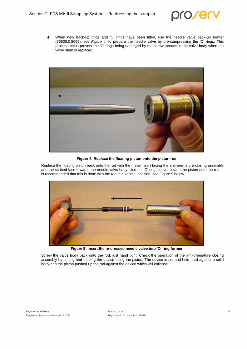
4. When new back-up rings and 'O' rings have been fitted, use the needle valve back-up former (86600.0.5055), see Figure 4, to prepare the needle valve by pre-compressing the 'O' rings. This process helps prevent the 'O' rings being damaged by the screw threads in the valve body when the valve stem is replaced.
Figure 4: Replace the floating piston onto the piston rod
Replace the floating piston back onto the rod with the metal insert facing the anti-premature closing assembly and the scribed face towards the needle valve body. Use the 'O' ring sleeve to slide the piston onto the rod. It is recommended that this is done with the rod in a vertical position, see Figure 5 below.
Figure 5: Insert the re-dressed needle valve into 'O' ring former
Screw the valve body back onto the rod, just hand tight. Check the operation of the anti-premature closing assembly by setting and tripping the device using the piston. The device is set and held hard against a solid body and the piston pushed up the rod against the device which will collapse.

Section 2: PDS MK II Sampling System – Re-dressing the sampler
Registered Address: 70 Queens Road, Aberdeen, AB15 4YE
Proserv UK Ltd 18 Registered in Scotland No 122029
Flow regulator assembly The Sample Chamber and Air Chamber are split with the flow regulator/prime nipple assembly remaining attached to the sample chamber. When the Air Chamber is split from the Sample Chamber it should be left to drain off the displacement fluid as described in a later section (illustrated in Figures 28 & 29).
Remove the flow regulator from its housing nipple using the flow regulator extractor. Normally, it is possible to pull the flow regulator from the nipple housing, if this is not the case then use the nut on the extractor to apply the pulling force required to do so, see Figure 6 below.
Figure 6: Removing the flow regulator assembly
1. After removal the flow regulator simply unscrews (end cap and body). Clean all the parts with safety solvent and blast dry with compressed air.
Ensure that the flow regulator is very clean and that there are no solid particles that could block the small hole in the body.
2. Inspect the piston nose for signs of wear and replace all the ‘O’ rings and back-up rings.
3. Re-assemble the flow regulator and replace in the nipple housing with the mesh filter towards the sample chamber. Re-connect the prime port/flow regulator nipple assembly to the sample chamber

Section 2: PDS MK II Sampling System – Re-dressing the sampler
Registered Address: 70 Queens Road, Aberdeen, AB15 4YE
Proserv UK Ltd 19 Registered in Scotland No 122029
Air chamber IMPORTANT: Invert the sampler (shuttle mechanism to top) for 3 minutes to release pressure from the chamber prior to draining.
After draining all the oil from the air chamber, (as described on page 36), disconnect the air chamber plug from the coiled tube. This can be done by unscrewing the Retaining ring then screwing in the air chamber plug extractor into the plug and pulling sharply until the pressure fitting is visible. While holding the coupling away from the air chamber insert the retaining fork between the air chamber and the pressure coupling, see Figure 7 below.
Figure 7: Securing the air chamber plug by inserting the retaining fork behind the pressure coupling.
Unscrew the coupling with the 7/16" AF spanners from the tool kit and remove the plug. Replace the ‘O’ rings and back-up rings and put the air chamber plug to one side.
Using the extractor tool attach it to the 1/8” Swagelok nut to extend the tube and remove the retaining fork. Next, unscrew the shuttle mechanism assembly from the air chamber . The air chamber plug extractor has a facility thread to retrieve the pressure tube coupling from the air chamber to aid the assembly, see Figure 8.

Section 2: PDS MK II Sampling System – Re-dressing the sampler
Registered Address: 70 Queens Road, Aberdeen, AB15 4YE
Proserv UK Ltd 20 Registered in Scotland No 122029
Figure 8: Retrieving the air chamber pressure coupling with the special tool.
Shuttle mechanism assembly
The internal seals of the shuttle mechanism assembly should not need to be serviced in the field unless exposed to very high temperatures or for more than four runs in a well, or a combination of both.
The removal and replacement of the internal ‘O’ rings are covered in the following section, please see below.
Removing the setting screw To remove the setting screw to re-dress the ‘O’ rings, remove the small internal circlip with circlip pliers, and unscrew fully from the shuttle mechanism assembly body. Replacing the ‘O’ rings can be difficult, but with the aid of ‘O’ ring Sleeve this task is made easier, see Figure 9.

Section 2: PDS MK II Sampling System – Re-dressing the sampler
Registered Address: 70 Queens Road, Aberdeen, AB15 4YE
Proserv UK Ltd 21 Registered in Scotland No 122029
Figure 9: Fitting new 'O' rings to the setting screw with the 'O' ring sleeve special tool.
Screw the setting screw back into the shuttle mechanism assembly and replace the circlip.
Replace all the outer ‘O’ rings and back-up rings on the shuttle mechanism and the top nipple.
Periodic workshop checks The following sub sections describe the workshop checks that should be carried out periodically.
Shuttle mechanism assembly With the shuttle mechanism separated from the air chamber, the internal valve seals can be replaced. Firstly, unscrew the retaining bush using the shuttle retaining bush extractor, see Figure 10.

Section 2: PDS MK II Sampling System – Re-dressing the sampler
Registered Address: 70 Queens Road, Aberdeen, AB15 4YE
Proserv UK Ltd 22 Registered in Scotland No 122029
Figure 10: Unscrewing the shuttle mechanism retaining bush.
If the retaining bush is difficult to unscrew by hand, a spanner can be used as the extractor is manufactured from hex bar.
Pull out the piston valve stem and trigger spring, see Figure 11.
Figure 11: Remove piston valve stem.
Using the needle valve key unscrew the retaining screw, see Figure 12.

Section 2: PDS MK II Sampling System – Re-dressing the sampler
Registered Address: 70 Queens Road, Aberdeen, AB15 4YE
Proserv UK Ltd 23 Registered in Scotland No 122029
Figure 12: Remove the retaining screw which secures the positioning bush and 'O' ring seals.
This will give access to the internal seals. Withdraw the complete assembly using the hooked dressing aid tool, see Figure 13. IMPORTANT: When assembling the Swagelock-Compression fittings to the shuttle mechanism it is CRITICAL that the flats on the hex are parallel to the centre. If they are not then the fitting will damage the sealing bore in the air chamber and also it will not be possible to remove the retaining screw fully.
Figure 13: Hook on to the removal bush to remove the shuttle valve stem seals.
The hook on the dressing aid is used to catch onto the removal bush, which is designed for this purpose.
Replace the seals and re-assemble the parts in the correct order finally securing the assembly with the retaining screw.
Smear a small amount of silicone grease on the 'O' rings before assembly.

Section 2: PDS MK II Sampling System – Re-dressing the sampler
Registered Address: 70 Queens Road, Aberdeen, AB15 4YE
Proserv UK Ltd 24 Registered in Scotland No 122029
Important, care is required not to damage the inner bore as this is sealing suface
Relief valve
A relief valve is built into the shuttle mechanism assembly to allow the bleed off of displacement fluid and prevent overpressure of the system from thermal expansion as the sampler is lowered into the well. With the shuttle mechanism detached from the air chamber, attach the hydraulic prime pump to the air chamber coiled tube (see Figure 14), and slowly build up pressure until the relief valve releases the pressure.
Figure 14: Testing the release pressure for the relief valve.
The pop-off pressure should be approximately 1700 p.s.i. and re-seat to between 1100 psi . If adjustment is required, then loosen the lock screw with a 1/16" A/F allen key and adjust the grub screw until the setting is correct, see Figure 15.
Figure 15: Adjusting the relief valve setting.
Tighten the lock screw and re-check the release pressure. Disconnect the hydraulic prime pump and fit the air chamber and air chamber plug.

Section 2: PDS MK II Sampling System – Re-dressing the sampler
Registered Address: 70 Queens Road, Aberdeen, AB15 4YE
Proserv UK Ltd 25 Registered in Scotland No 122029
Mechanical clock Wind the clock up to its full running time (this will depend on the range of the clock). Place the clock on a flat surface so that the clock body is supported but the cone and the winding head are free to rotate. Note the time, and check the clock time hourly against your wristwatch. Repeat this procedure with the clock positioned horizontally, vertically and inverted.
Should any problems occur with the clock, return the unit to Proserv for servicing.
Anti-premature closing assembly With the anti-premature closing assembly still attached to the piston rod, loosen the spring retaining nut from the brake collet. Next unscrew the retaining nut fully, this should be done on a clean flat surface and with the rod in a vertical position, see Figure 16.
Figure 16: Dismantling the anti-premature closing assembly.
Remove the piston rod and rod connector. The spring retainer and spring will come with it. Take care not to lose the four steel balls which may fall out while dismantling these parts.
With the assembly separated, inspect the rod connector, balls and brake collet and check for signs of wear or damage. Check that the rod connector is tight on the rod and if not tighten with a suitable spanner by gripping the rod in a vice with protected jaws to prevent marking the rod surface.
Coat the stainless steel balls with a light film of grease and balance them in their ports in the ball retainer.
Gently lower the brake collet over the ball retainer taking care that the balls remain in their ports and are not dislodged into the centre. Once this is completed, push the balls towards the outside of the ball retainer and lower the rod connector into place, then screw up tight.

Section 2: PDS MK II Sampling System – Re-dressing the sampler
Registered Address: 70 Queens Road, Aberdeen, AB15 4YE
Proserv UK Ltd 26 Registered in Scotland No 122029
Lock and release the assembly to check the operation. Lock by griping the rod and pulling with two fingers behind the ball retainer collet. Release by griping the ball retainer and spring retainer between thumb and forefinger and the unit should collapse.
The brake collet and the ball retainer should collapse leaving no space between the two. If there is a space, probably, one or more of the stainless steel balls may have fallen into the centre of the ball retainer. Check and re-assemble, then check again.
Flow regulator To test the operation of the flow regulator set up a test rig as shown in Figure 17.
This test rig can be supplied by Proserv on request.
Figure 17: Flow regulator test rig.
When using the prime hand pump in conjunction with the flow regulator test rig the purpose of the 1/4" NPT grub screw is to plug the port when the 0-6,000 p.s.i. gauge is removed on the hand pump as pressures used during this test exceed that of the gauge.
1. Using the higher pressure end cap (for reservoir pressures between 5000-15000 p.s.i. with the small port 0.062”[1.6 mm]), the flow regulator piston and any flow regulator body inserted into the test unit. Apply 8000 p.s.i; the secondary gauge should indicate between 300 p.s.i and 500 p.s.i. on the opposite side of the flow regulator (ratio of 16:1).
To prevent any air lock distorting the secondary outlet pressure, open the valve and allow a slight flow of hydraulic fluid through the system, then close the valve very slowly.
2. Similarly, the lower pressure flow regulator (reservoir pressures up to 5000 p.s.i.) is tested by fitting the end cap with the large port (0.156” [4 mm]). An applied pressure of 8000 p.s.i. should give a secondary pressure reading of between 1400 p.s.i. and 1600 p.s.i. (ratio of 5:1).

Section 2: PDS MK II Sampling System – Re-dressing the sampler
Registered Address: 70 Queens Road, Aberdeen, AB15 4YE
Proserv UK Ltd 27 Registered in Scotland No 122029
3. If pressure rises above these given levels the matching end cap and piston should be returned to the manufacturer for repair.
The end cap and piston are matched and tested accordingly, and on no account should these be separated and used on non-matching pieces unless also tested as described above.
Piston sample chamber assembly Before assembly the threads of the sample chamber must be checked for signs of wear and damage or worn parts must be replaced before tool is returned into service.
Re-dress the lower section of the sampler (sample chamber) as far as the flow regulator/prime nipple but DO NOT set the anti-premature closing assembly. Assemble as normal but use the transfer lock sleeve to push the needle valve body to seal in the sample chamber as though the sampler had taken a sample, see Figure 18.
Figure 18: Push the needle valve body into sample chamber with the transfer lock sleeve
Screw the transfer adaptor into the needle valve body and inject oil into the sample chamber until it is full. Next close the needle valve and the prime port nipple and disconnect the pump.
Screw the transfer sleeve assembly onto the flow regulator/prime nipple assembly, see Figure 19 (The flow regulator should not be fitted).

Section 2: PDS MK II Sampling System – Re-dressing the sampler
Registered Address: 70 Queens Road, Aberdeen, AB15 4YE
Proserv UK Ltd 28 Registered in Scotland No 122029
Figure 19: Connect the sample chamber to the transfer bench.
Pressure up the system to 15000 p.s.i., if this test is satisfactory with no leaks, bleed off the pressure.
If a leak is discovered on the needle valve seat, the complete unit must be returned to the manufacturer for replacement or repair.

Section 3: PDS MK II Sampling System – Well‐site Checks
Registered Address: 70 Queens Road, Aberdeen, AB15 4YE
Proserv UK Ltd 29 Registered in Scotland No 122029
Well site checks to be carried out before sampling 1. Insist that a scraper tool is used to clear the walls of the well to full depth.
2. At same time the winch operator can calibrate the depth counter.
3. a) Information about the bottom hole temperature and pressure are required in order for the correct choke (flow regulator) and prime pressure to be chosen.
b) Ensure that the choke (flow regulator) is inserted facing the correct direction.
4. Check the depth correlation for sampling.
5. Check that the length of the lubricator is sufficient for the number of samplers to be run.
6. Ensure that you have a flexible knuckle joint for times when you may be using a string of other measuring tools. This makes it very easy to insert the sampler into the lubricator section (closed well).
7. a) Check all clocks on site to see that they function correctly and keep good time.
b) When setting the clock, allow time for the well site operations to run the sampler and time to reach depth (example running in rate 60 ft/min. to 1000 ft will take 16.7 minutes), plus a 30 minute span of the sampling time to be sure the sample is taken at the required depth. Plus the time to load the sampler(s) into the lubricator, pressure test.
c) Always allow plenty of time for the sampler to fill e.g. 2 or 3 times the recommended fill time.
8. IMPORTANT: Always check that the shuttle setting screw is released before running the sampler(s).
9. If possible, it is recommended that you check the well fluid you intend to sample, to see if there are any sandy or salt particles present. If so, a filter attachment may be required.
10. A clean area is required for the preparation of the sampler(s) and sample transfer.

Section 4: PDS MK II Sampling System – Running the Sampler
Registered Address: 70 Queens Road, Aberdeen, AB15 4YE
Proserv UK Ltd 30 Registered in Scotland No 122029
Preparing and Running the PDS sampler It is assumed that prior to arrival at the well site; the sampler has had new 'O' rings fitted throughout.
Piston sample chamber Unscrew the nose cone and the flow regulator/prime nipple assembly from the sample chamber.
Screw the needle valve extractor tool into the needle valve body and pull the internal assembly from the sample chamber, Figure 20.
Figure 20: Removal of the piston rod assembly from the sample chamber
1. When removing the piston rod assembly from the sample chamber, it is important that you support the rod to prevent bending.
For this operation the Posi-Lock Pin should be uppermost. If not, the Posi-Lock Pin and spring may fall out of the valve body and be lost.
2. Remove the Posi-Lock Pin and spring.
3. Next remove the extractor.
4. Using the needle valve key, ensure that the needle valve and transfer port plug are fully closed, see Figure 21.
There is a threaded hole on the end of the needle valve body; this is used with SPS surelock assembly but serves no purpose in the standard operation of the MK II sampler.

Section 4: PDS MK II Sampling System – Running the Sampler
Registered Address: 70 Queens Road, Aberdeen, AB15 4YE
Proserv UK Ltd 31 Registered in Scotland No 122029
Figure 21: Checking the needle valve and transfer port plug are closed
Check that the rod is screwed fully into the anti-premature closing assembly and needle valve body. Check that the 'O' ring protector covers both 'O' rings and that the tapered end of the protector is flush with the end of the body.
Check that the piston slides freely along the rod and is assembled with the grooved face (A) towards the valve body, see Figure 22.
Figure 22: Checking the piston is aligned correctly
Set the anti-premature closing assembly by holding the rod and gently pulling on the top of the ball retainer. A clicking sound will be heard as the device locks into position and becomes rigid, see Figure 23.
Section 4: PDS MK II Sampling System – Running the Sampler
Registered Address: 70 Queens Road, Aberdeen, AB15 4YE
Proserv UK Ltd 32 Registered in Scotland No 122029
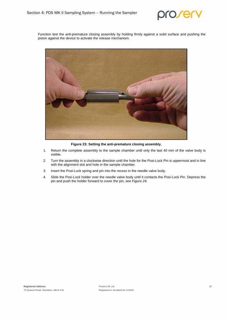
Function test the anti-premature closing assembly by holding firmly against a solid surface and pushing the piston against the device to activate the release mechanism.
Figure 23: Setting the anti-premature closing assembly.
1. Return the complete assembly to the sample chamber until only the last 40 mm of the valve body is visible.
2. Turn the assembly in a clockwise direction until the hole for the Posi-Lock Pin is uppermost and in line with the alignment slot and hole in the sample chamber.
3. Insert the Posi-Lock spring and pin into the recess in the needle valve body.
4. Slide the Posi-Lock holder over the needle valve body until it contacts the Posi-Lock Pin. Depress the pin and push the holder forward to cover the pin, see Figure 24.

Section 4: PDS MK II Sampling System – Running the Sampler
Registered Address: 70 Queens Road, Aberdeen, AB15 4YE
Proserv UK Ltd 33 Registered in Scotland No 122029
Figure 24: Fitting the Posi-Lock Pin.
Continue to push forward as far as possible. Then insert the push rod into the holder and push slowly forward until the shoulder hits the end of the holder, see Figure 25.
Figure 25: Inserting the push rod to push the needle valve body into the sample chamber.
If there is some resistance during this operation the Posi-Lock Pin will not be in line with the alignment groove in the chamber. To solve this problem, turn the holder slightly to the left or right until the push rod can be pushed forward easily.
1. Remove the holder and push rod, screw on the nose cone and tighten fully.
2. Clamp the sample chamber in a vertical position on the transfer bench with the nose cone pointing downward. First check that the assembly is in the set position. To check that the anti-premature closing assembly is set correctly, measure the length internally from the top of the sample chamber to the top of the anti-premature closing mechanism, which should be no greater than 45 mm,.
Then push the 5/16" diameter clear plastic tube into the hole in the centre of the anti-premature closing assembly..
3. Feed the filler funnel over the tube and screw it into the top of the chamber.
4. Connect the vacuum pump reservoir to the plastic tube. Connect the vacuum pump to the other side of the reservoir using a short length of plastic tube.
5. Almost fill the filler funnel with synthetic displacement oil (this is approximately 640 ml).

Section 4: PDS MK II Sampling System – Running the Sampler
Registered Address: 70 Queens Road, Aberdeen, AB15 4YE
Proserv UK Ltd 34 Registered in Scotland No 122029
6. Squeeze the handle of the vacuum pump repeatedly to draw the oil down into the chamber, see Figure 26.
7. When the funnel is empty, use the vacuum pump to remove any excess oil from the chamber until just level with the top of the anti-premature closing assembly.
8. Remove the tube and the funnel.
Figure 26: Filling the sample chamber with displacement fluid.
Fit and hand tighten the flow regulator/prime nipple assembly to the sample chamber and put to one side keeping in a vertical position until required to assemble the complete sampler.

Section 4: PDS MK II Sampling System – Running the Sampler
Registered Address: 70 Queens Road, Aberdeen, AB15 4YE
Proserv UK Ltd 35 Registered in Scotland No 122029
Flow regulator selection To help aid the selection of the correct flow regulator end cap and body, the options available for different well pressure and temperature are shown in Table 1.
Table 1: Choke selection guide for the PDS sampler
The optimum fill time is approximately 4 minutes and the table is constructed to reflect this. The table is split into two parts, one for low-pressure wells (up to 5000 p.s.i.) and the other for high-pressure wells (5000-15,000 p.s.i.). The differential in flow regulator set up is the size of the port in the end cap; the large port (0.156”) is for low pressures and the small port (0.062”) is for high pressures. The well pressure also determines which flow regulator body should be used. There are 4 different sizes to choose from: MK1, MK2, MK3 and MK4, Table 1 indicates which to choose for different well parameters.
The Flow regulator only alters the fill time and has no bearing on the prime pressure. The pressure differential ratios of the two flow regulators for the sampler are as follows:
• Low Pressure (Large front port): 5:1
• High Pressure (Small front port): 16:1
Numbers refer to Choke Size (Flow regulator body MK 1-4)
Temperature (Deg C)
Pressure differential Port size 50 60 70 80 90 100 110 120 130 140 150 160 170 180
Pres
sure
(psi
)
500 3 3 3 3 3 3 3 3 3 4 3 3 3 3
Larg
e P
ort (
0.15
6")
1000 3 3 3 3 3 3 3 3 3 3 3 3 3 3
1500 3 3 3 3 3 3 3 3 3 3 3 3 3 3
2000 3 3 3 3 3 3 3 3 3 3 3 3 3 3
2500 3 3 2 2 2 2 2 2 2 2 2 2 2 2
3000 4 2 2 2 2 2 2 2 2 2 2 2 2 2
3500 2 2 2 2 2 2 2 2 2 2 2 2 2 2
4000 2 2 2 2 2 2 2 2 2 2 2 2 2 2
4500 2 2 2 2 2 2 2 2 2 2 2 2 2 2
5000 2 2 2 2 2 - - - - - - - - -
- - - - - 4 4 4 4 4 4 4 4 4
Sm
all P
ort (
0.06
2")
6000 4 4 4 4 4 4 4 4 4 4 4 4 4 4
7000 4 4 4 4 4 4 4 4 4 4 4 4 4 4
8000 4 4 4 4 4 4 4 4 3 3 3 3 3 3
9000 3 3 3 3 3 3 3 3 3 3 3 3 3 3
10000 3 3 3 3 3 3 3 3 3 2 2 2 2 2
11000 2 2 2 2 2 2 2 2 2 2 2 2 2 2
12000 2 2 2 2 2 2 2 2 2 2 2 2 2 2
13000 2 2 2 2 2 2 2 1 1 1 1 1 1 1
14000 2 2 2 2 2 1 1 1 1 1 1 1 1 1
15000 1 1 1 1 1 1 1 1 1 1 1 1 1 1

Section 4: PDS MK II Sampling System – Running the Sampler
Registered Address: 70 Queens Road, Aberdeen, AB15 4YE
Proserv UK Ltd 36 Registered in Scotland No 122029
It is very important that these ratios are maintained, and the regulators are tested periodically. The flow regulator can be tested using the flow regulator test rig as described on page 26, Figure 17.
If the flow regulators are not maintained satisfactorily then there is a risk of sampler failure resulting in premature filling of the sampler before reaching the sampling depth. The reason for this is with a reduction in the differential pressure ratio across the flow regulator the relief valve may crack open allowing displacement fluid into the air chamber prematurely. The relief valve pressure should only need to be lowered for extreme conditions, for example, if the well temperature is extremely high and/or the well pressure extremely low.
Example:
• Well Pressure 3,000 p.s.i.
• Well Temperature 85 oC
• Fill Time Required 4 minutes
The correct selection is the end cap with the large port (0.156 ") and a MK2 Body.
The MK1 Body should only be used for well pressures over 10000 p.s.i. When assembling the flow regulator, ensure that the flow regulator body is free from any solid particles as these could block the end cap port and cause failure. Before screwing the flow regulator together, smear a small amount of nickel anti-seize on the threads.
Assemble the flow regulator assembly with the flow regulator/prime nipple assembly ensuring that the wire mesh filter is facing towards the sample chamber as indicated in Figure 27.
If water or glycol water has been used as the displacement fluid, the unit must be cleaned and oiled after use as the piston is manufactured from high carbon steel and will corrode.
Figure 27: Insertion of the flow regulator assembly into the prime nipple assembly

Section 4: PDS MK II Sampling System – Running the Sampler
Registered Address: 70 Queens Road, Aberdeen, AB15 4YE
Proserv UK Ltd 37 Registered in Scotland No 122029
Air chamber
Insert the air chamber plug retaining ring extractor into the lower end of the air chamber and unscrew the retaining ring from the air chamber, see Figure 28
Figure 28: Removing the air chamber retaining ring.
Screw the air chamber plug extractor into the end of the plug DO NOT OVERTIGHTEN. Hold the air chamber and pull the plug free of the air chamber until the connecting nut on the tube is visible and fit the setting fork behind the nut to hold the plug clear of the chamber, see Figure 29. DO NOT OVER STRETCH THE INTERNAL TUBING COIL. Tilt the chamber over a suitable container to allow any remaining oil to drain out.
Figure 29: Removing the air chamber plug to drain the Air Chamber
When the air chamber is fully drained remove the setting fork and re-fit the plug into the chamber. Screw the retaining ring into the end of the air chamber and tighten fully.

Section 4: PDS MK II Sampling System – Running the Sampler
Registered Address: 70 Queens Road, Aberdeen, AB15 4YE
Proserv UK Ltd 38 Registered in Scotland No 122029
Shuttle mechanism assembly Check that the shuttle mechanism assembly is fully tightened into the air chamber.
Secure the air chamber assembly in the transfer bench clamps. Slide the setting tool over the piston valve stem and push hard on the setting tool to overcome the trigger spring until it is hard against the face of the shuttle mechanism. Hold the tool in this position and screw in the setting screw until tight to lock the piston valve stem in position, see Figure 30
Figure 30: Setting the shuttle mechanism in the locked position
Remove the setting tool and screw in the trigger assembly, just hand tight. Next lift the trigger lever with a finger until it touches the sleeve to ensure that it has free movement, see Figure 31.
Figure 31: Checking free movement of the trigger lever
Screw on the container tube and tighten fully. Lay down the sample chamber assembly in a horizontal position and screw together with the air chamber assembly. It is advisable to use support blocks so that the two units

Section 4: PDS MK II Sampling System – Running the Sampler
Registered Address: 70 Queens Road, Aberdeen, AB15 4YE
Proserv UK Ltd 39 Registered in Scotland No 122029
are level to prevent damaging the threads. Ensure that the threads are properly aligned and DO NOT use excessive force.
Priming the sampler Hold the prime port nipple closed with the ring spanner, then unscrew and remove the prime port plug, see Figure 32.
Figure 32: Removing the prime port plug.
Check the hydraulic pump is filled with the synthetic displacement oil and connect the hydraulic hose to the hand pump. Fit the prime port adaptor onto hose and pump oil through the hose and adaptor to remove any air. Remove prime port adaptor from hose and screw it onto the prime port nipple whilst retaining the ring spanner in place so that the nipple can be opened when all is connected. Just tighten the adaptor hand tight against the flat ‘O’ ring face. DO NOT OVER TIGHTEN. Connect the other end of the hose to the prime port adaptor. Before tightening the connection, first fill the connection hose with oil to remove any air.
Open the prime port nipple half-to-one turn with the ring spanner. Prime the fluid pressure in the system until a steady reading 4,000 p.s.i. is registered on the pump gauge, see Figure 33. Initially there may be fluctuations in the pressure as the small amount of air in the sampler is compressed (this is normal).

Section 4: PDS MK II Sampling System – Running the Sampler
Registered Address: 70 Queens Road, Aberdeen, AB15 4YE
Proserv UK Ltd 40 Registered in Scotland No 122029
Figure 33: Priming the displacement fluid pressure.
Check all joints for leaks. If the test is satisfactory, adjust the pressure to that required for the well parameters, see below with reference to Figure 34.
If during the test the pressure does not hold, first check the shuttle mechanism valve is in the set position as this is the most likely cause for pressure loss.
Prime pressures for running the Positive Displacement Sampler Together with the flow regulator end cap and flow regulator body size selection for a sampler run, a suitable prime pressure must be chosen dependent on the well pressure. Figure 34 provides details for the selection of the prime pressure based on the well parameters of temperature and pressure.
Prime pressure selection Generally, there are just two prime pressures to consider based on the well pressure characterisation of low (1000-5000 p.s.i.) with a prime pressure of 1000 p.s.i. and high (5000-15,000 p.s.i.) with a prime pressure of 300 p.s.i.
The purpose of priming the sampler is to provide an initial overpressure in the sample chamber and thereby prevent any contamination caused by pre-sampling during the running in operation. With thermal expansion of the Synthetic displacement oil, the effect is to have an internal pressure greater than the reservoir pressure. For further reference on prime pressure (see Figure 34), the minimum differential pressure should be chosen.

Section 4: PDS MK II Sampling System – Running the Sampler
Registered Address: 70 Queens Road, Aberdeen, AB15 4YE
Proserv UK Ltd 41 Registered in Scotland No 122029
Reference graph
REFERENCE CHART - TEMPERATURE EFFECT ON PRIME PRESSURE FOR DISPLACEMENT OIL
0
5000
10000
15000
0 20 40 60 80 100 120 140 160
TEMPERATURE (DEG C)
PR
ESSU
RE
(PSI
)
1000 PSI Prime Pressure
300 PSI Prime Pressure
0 PSI Prime Pressure
Figure 34: Internal pressure developed by the synthetic displacement oil from thermal expansion.

Section 4: PDS MK II Sampling System – Running the Sampler
Registered Address: 70 Queens Road, Aberdeen, AB15 4YE
Proserv UK Ltd 42 Registered in Scotland No 122029
Finally, once the required prime pressure has been set for the well, close and tighten the prime port nipple. Bleed off the pressure from the hand pump. Holding the prime port nipple closed with the spanner, unscrew the hydraulic hose, and refit the prime port nipple plug. Place the sampler aside until ready to run into the well.
Setting the mechanical clock With the sampler almost ready to run, one of the final operations to be completed is the selection and setting of an appropriate clock time to cover the time required for well site operations and running of the sampler(s) in the well. Standard clock maximum times are: 21/2, 5, 10 and 24 hours. . With longer run time clocks, each division also becomes larger. Operators should check the run time of a clock at the well site to see that they are functioning correctly.
To set a clock delay time, hold the clock body with the cone end facing and the scribed line on the body uppermost. Locate the winding head pin in the slot in the cone and push fully forward to engage, see Figure 35.
Figure 35: Engaging the clock winding head.
At this stage, the scribed line on the body and the zero mark on the winding head should be aligned. Hold the body steady and turn the winding head until the required delay time is aligned with the scribed line, see Figure 36.
IMPORTANT: DO NOT OVERWIND THE CLOCK AS IT CANNOT BE TURNED BACK.

Section 4: PDS MK II Sampling System – Running the Sampler
Registered Address: 70 Queens Road, Aberdeen, AB15 4YE
Proserv UK Ltd 43 Registered in Scotland No 122029
Figure 36: Setting the clock delay time.
Remove the winding head. Look into the open end of the clock housing and turn the sampler until the locating pin in the end of the trigger sleeve is uppermost. Hold the clock with the coned end facing into the open end of the clock housing, and the scribed line setting line uppermost.
Rotate the clock as follows depending on the time set:
A. For a clock set for up to half of its full range (for example, up to 5 hours on a 10 hour clock), rotate the clock approximately 30 degrees to the left.
B. For a clock set for more than half of its full range (for example, over 5 hours on a 10 hour clock), rotate the clock approximately 30 degrees to the right, see Figure 37.
Figure 37: Rotation of the clock before insertion into the housing.
Push the clock into the housing as far as it will go. Slowly rotate the clock backwards, for example, to the right if set as in 'A', and to the left as in 'B', above. Maintain forward pressure while doing this and the clock will move forward another 6mm when the trigger locating pin is engaged, see Figure 38.

Section 4: PDS MK II Sampling System – Running the Sampler
Registered Address: 70 Queens Road, Aberdeen, AB15 4YE
Proserv UK Ltd 44 Registered in Scotland No 122029
Figure 38: Positioning the clock to engage the trigger locating pin.
Now attach the 5/8" sucker rod top nipple and tighten fully.
The final operation to be completed, immediately before the sampler is lifted for running in, is to back off the setting screw to release the Piston Valve Stem of the shuttle mechanism. The screw should be unscrewed fully until it is backed off hard against the circlip, see Figure 39. A feint ‘click’ may be heard as this is done, indicating that the Piston Valve Stem is set against the trigger mechanism.
IMPORTANT: If the operator fails to back off the setting screw, the sampler will fail to operate. (This is possibly the most common cause of failure).
Figure 39: Setting screw release.
The sampler is now ready to be run in the well. Run the sampler at no more than 200 feet per minute to reach the sampling depth. Leave the sampler at depth for at least 15 minutes after the set clock time for taking the sample, and then pull out of the well.
A
B

Section 5: PDS MK II Sampling System – Short Form Check List
Registered Address: 70 Queens Road, Aberdeen, AB15 4YE
Proserv UK Ltd 45 Registered in Scotland No 122029
Short form check list of the PDS sampler running procedures: Experienced Proserv engineers have compiled this short form checklist of the operating procedure for the PDS. The list is designed to help speed up procedures for the operating engineers who are familiar with the PDS equipment. Each item highlights important checks that must be carried out while setting up the sampler.
1. Check the Operating Tools and Accessories (see Identification Chart pages 56-57, Figure 43 and Figure 44).
2. Check condition of the 'O' rings and back-up rings throughout the sampler and replace as deemed necessary.
3. Check function of flow regulators (see page 25, Figure 17).
4. Assemble the needle valve body assembly, rod, floating piston and anti-premature closing assembly. Check needle valve is closed, and also check that Posi-Lock Pin, transfer port plug and 'O' ring protector are in place.
5. Make sure sample the chamber is clean and free from scratches, set anti-premature closing assembly in engaged position (see page 32, Figure 23) and carefully return the rod assembly into the sample chamber (see page 33).
6. Screw on the nose cone and fill the sample chamber with the synthetic displacement fluid, see page 34, Figure 26.
7. Select and assemble the required flow regulator, (see page 35) insert the unit into the flow regulator/prime nipple assembly.
Metal gauze filter toward the front of the sampler.
8. Connect the flow regulator/prime nipple assembly complete with the protection cap to the sample chamber.
9. Check the air chamber is drained and contains no residual displacement fluid from previous use, see page37, Figure 29.
10. Check the shuttle mechanism assembly and relief valve function correctly.
Should be checked after every run and after re-dressing.
11. Completely assemble the air chamber and set the shuttle mechanism assembly in its closed position using the setting tool (see page 38, Figure 30).
12. Assemble trigger mechanism and container tube by screwing them to the shuttle mechanism assembly.
13. Connect the sample chamber and air chamber and check all joints are correctly tightened.
14. Prime the sampler with the required prime pressure (see pages 40-41, Figures 33-34). Remember to remove any air from the hydraulic hose before pressurising (see page 39).
15. Set the clock to the time required (do not over-wind) and locate in clock housing. Screw on the top nipple. Finally, immediately before the sampler(s) are lifted into the lubricator back off the shuttle setting screw against circlip (a click should be heard). The sampler is now ready to take a sample. Note the time.
16. After the set sampling time has elapsed recover the sampler from the well. When at surface immediately check the Posi-Lock Pin is visible in the recess port as an indication that a sample has been taken. Remove sampler top nipple and clock, unscrew container tube and trigger. Screw on protection cap on to shuttle mechanism
17. Bleed off any pressure in the air chamber through the prime port nipple. Then separate the sampler into two halves, this must be at the junction between the air chamber assembly and the flow regulator/prime nipple assembly.
18. Remove the flow regulator from the flow regulator/prime nipple assembly with the special tool (See page 18, Figure 6).
19. The flow regulator should be stored inside a polythene bag in its box.

Section 5: PDS MK II Sampling System – Short Form Check List
Registered Address: 70 Queens Road, Aberdeen, AB15 4YE
Proserv UK Ltd 46 Registered in Scotland No 122029
20. The transfer bench should be checked and set up in a suitable work area in preparation for sample transfer (see page 81 refer items A to E).
21. A sample cylinder should be set up correctly filled and evacuated of air using the hand vacuum pump ready for transfer (see separate cylinder operating procedures).
22. Remove the nose cone from the sampler and immediately replace with the transfer lock sleeve. THIS IS VERY IMPORTANT TO MAKE THE SYSTEM SAFE
23. Pressurise the transfer bench to 1,000 p.s.i. above the anticipated transfer pressure. Check the pump for leaks then drop the pressure back to zero.
24. Connect the hose assemblies to the sampler and sample cylinder then bleed the air out of the lines and the rest of the system (see page 82, refer items G to J).
25. If necessary connect adaptors to the cylinder valves, screw the transfer adaptor into the transfer port of the needle valve, locate the sampler with the cylinder (take great care to ensure easy fitting and not to damage the threads). Tighten transfer adaptor into cylinder valve (see page 83, item M).
26. Evacuate the air from the transfer port adaptor through the evacuation port on the top of the cylinder using the vacuum hand pump ensuring the cylinder valve is open, see page 83, Figure 61. When maximum vacuum is reached close the vacuum port assembly and remove the hand pump. Leave cylinder valve fully open.
27. a) Check that V7 and V5 are closed and all other valves are open. Pressurise the entire system (both sides of the sample chamber) to 1,000 p.s.i. above the bottom hole pressure with the exception of the top area in the cylinder and the transfer adaptor, which are under vacuum. When the pressure is reached shut off the air regulator to the pump and allow the system to stabilise.
b) Slowly open V5 to lower the pressure in the system. Observe for a kick in the pressure gauge reading as it lowers and note the pressure at which this occurs. The kick is caused by movement of the floating piston and as it bottoms out in the sample chamber due to the presence of gas in the sample and thus is an accurate measure of the opening pressure which can be recorded at this time (the temperature should also be recorded for reference – a thermometer taped to the body of the sample chamber or ambient temperature may be the only reference). This process may be repeated as many times as required. If no opening pressure is found using this method steps 28 and 29 should be followed instead.
The purpose of an opening pressure is normally to check the validity of a sample when compared with other samples taken from the same zone.
28. Fine adjustments to the pressure setting should be made so that the pressure reads exactly 1000 p.s.i. This is done by small movements of any valve that is known to be in the open position or by the hand pumping.
29. After the pressure has stabilized, open the needle valve two complete turns and observe the opening pressure. At this stage you should record the opening pressure and approximate temperature of the sample.
30. To begin the transfer raise the pressure in the system to approximately 1500 p.s.i above an estimated bubble point based on information of the reservoir, alternatively, approximately 1,500 p.s.i. above the known pressure that the sample was taken at.
31. When the pressure has stabilized the sample can be transferred to the cylinder by the preferred procedure (see options page 84, 1, 2 or 3).
32. When the sample has been transferred into sample cylinder, close the top valve on the sample cylinder. Close V4 and ensure V7 and V8 are also closed.
33. Disconnect the sampler from the piston sample cylinder and leave transfer adaptor in sampler transfer port.
At this stage the sample chamber can be removed completely from the transfer bench, to do so take the following steps:
• First make a note of the pressure in the system.
• Open V11 and close V4 lower the pressure in the system to zero through V5.

Section 5: PDS MK II Sampling System – Short Form Check List
Registered Address: 70 Queens Road, Aberdeen, AB15 4YE
Proserv UK Ltd 47 Registered in Scotland No 122029
• Using the compressed air line push the water/glycol from the sample chamber back into the reservoir or alternatively into a suitable container through V12 (see page 15, Figure 1).
• Remove the hose from the flow regulator/prime nipple assembly and manifold and close V11.
• Remove the sample chamber from the transfer bench and put to one side for servicing (whenever possible the anti-premature closing assembly should be removed and cleaned to prevent rusting).
• Close V5 and re-pressurise the system to the noted pressure, allow to stabilise, then open V4.
34. If the option was taken to leave the sample chamber mounted on transfer bench, slide it away from the cylinder in the body clamps allowing for free rotation of the cylinder when measuring the bubble point of the sample (see page 86, Figure 62).
35. The sample should only be transferred in a single phase state i.e. with no free gas phase. Agitate the sample cylinder by rotating it through 180 degrees in both directions to allow the mixing device inside the cylinder to move through the sample. Be sure the clamping screws on the cylinder holder are securing the cylinder before inverting the cylinder. If a pressure drop is observed then the pressure will need to be increased and remain stable before continuing with the BP measurement.
36. If re-pressurising has been carried out to achieve a stable sample pressure then it can be raised by a further 1,500 p.s.i. This may provide a more successful starting point for the bubble point evaluation, for which, at least three co-ordinate points are needed for extrapolation with the sample in single-phase.
37. When ready to begin the BP measurement V4 can be closed (this will reduce the volume of the system to its minimum).
38. Check that V8 is closed then quickly open and close V7 to allow the constant volume assembly to fill (2 ml). Drain off the 2 ml of water/glycol by opening and closing V8. Again, agitate the sample by rocking the cylinder in the holder then note the stabilised pressure (approximately stabilisation time 2 minutes).
39. Procedure 38 is repeated and the data plotted (volume expansion – 2ml steps versus the sample pressure) to evaluate the bubble-point of the sample (for reference graph see page 88, Figure 64).
IMPORTANT: The exact procedure for volume change and settling time of the sample should be observed every cycle. The process (Bubble Point Analysis) can be repeated as many times as required.
40. The bubble-point graph is plotted with 2 ml volume steps sample expansion on the X-axis and the sample pressure (p.s.i.g.) on the Y axis. The intersection at which the two extrapolated lines converge is known as the bubble point for that sample. A temperature for the sample should be recorded and the closest reference to this that can easily be measured is the ambient temperature.
41. For safe transportation the pressure in the cylinder is reduced to produce a gas cap in the sample. A general rule followed is to reduce the water/glycol below the piston by 10% of the total volume or to a pressure recommended by the customer.
It is important to take a note of the volumes, temperature, pressure and the serial number of the cylinder.
42. Close the bottom valve of the cylinder, drop pressure in the transfer bench system and hoses and remove the hose adaptors and fit the cylinder valve port plugs.
43. Remove the cylinder from the holder and replace the protection caps, then store the cylinder in its box for transportation.
44. Label the sample cylinder and fill out a sampling sheet in duplicate, include one copy with the piston sample cylinder.
45. Recycle the transfer fluid from the sample chamber back into the reservoir or into a suitable container via V12 and remove the sample chamber from the transfer bench (see page 15, Figure 1).
46. The complete sampler should be stripped, cleaned and redressed as necessary ready for re-use.

Section 5: PDS MK II Sampling System – Short Form Check List
Registered Address: 70 Queens Road, Aberdeen, AB15 4YE
Proserv UK Ltd 48 Registered in Scotland No 122029
Preventing sampler failure Below is a quick check-list, together with reasons that may cause the sampler to fail:
1. Check: The needle valve is closed.
Reason: Loss of sample when the transfer port plug is removed.
2. Check: The anti-premature closing assembly has been function tested and set.
Reason: The sampler will close immediately after being triggered, and no sample
will be collected.
3. Check: There is no contamination in the flow regulator body.
Reason: A complete blockage or partial blockage may occur due to dirt in the small
back hole. This would slow down or stop sampling.
4. Check: The setting screw is fully backed off against the circlip.
Reason: The shuttle mechanism will remain locked in the set position preventing the mechanism from triggering.
5. Check: The flow regulator is facing in the correct direction.
Reason: The piston in the flow regulator would shut the flow off immediately after
the tool was triggered, preventing the flow of the displacement fluid into the
air chamber.
6. Check: The trigger mechanism is free moving (up/down) when in situ.
Reason: If the trigger mechanism sticks, it will not drop down into the slot of the cam follower when the clock unwinds, therefore preventing the piston valve stem from springing back and releasing the flow of the displacement fluid.
7. Check: The sampler clock is set for the correct duration.
Reason: Sampler triggered outside the sampling window, at the wrong depth, sampling the wrong fluid or non at all.
8. Check: The sampler clock is running before fitting into the sampler.
Reason: The sampler may not be triggered.
9. Check: The sampler clock has been serviced at regular intervals.
Reason: The clock may not fully unwind.

Section 5: PDS MK II Sampling System – Short Form Check List
Registered Address: 70 Queens Road, Aberdeen, AB15 4YE
Proserv UK Ltd 49 Registered in Scotland No 122029
10. Check: The relief valve is set at the correct pressure (especially not to low).
Reason: With a low setting, premature bleed off of the displacement fluid could result in sampling at the wrong depth. This would result in a sample that is not representative.
11. Check: The seals in the shuttle mechanism assembly hold pressure.
Reason: Premature bleed off of the displacement fluid could result in sampling at the wrong depth. This would result in a sample that is not representative.
12. Check: The piston valve stem is free to move before setting.
Reason: If the piston valve stem sticks the sampler will not fire.
13. Check: The correct prime pressure is used for the well conditions.
Reason: A high build up in pressure in the sample chamber damaging the seals and causing the needle valve body assembly and piston to jam.
14. Check: There is no free excess thread tape when assembling the air chamber (NPT fittings).
Reason: Thread tape blockage in the shuttle mechanism assembly, will prevent flow of displacement fluid and no sample can therefore be captured.
15. Check: The integrity of the location pin at the back of the trigger mechanism.
Reason: A loose, bent or missing pin may cause cam slot misalignment, which results in premature triggering or failure of the sampler.

Section 6: PDS MK II Sampling System – Well Simulation Test
Registered Address: 70 Queens Road, Aberdeen, AB15 4YE
Proserv UK Ltd 50 Registered in Scotland No 122029
Well simulation test The well simulation test is an option available to do a full simulated sampler run in the workshop using the transfer system and requires the purchase of a special item (well test simulator unit).
Introduction The well test simulator was designed by Proserv initially as a training aid, but there are a number of applications for its use. A sampler function test can be carried out in the workshop before sending the equipment to the well site. This is a complete function test of the sampler, but it can also serve to further familiarise the operating engineer with the sampler or for the training of personnel in the operation of the equipment.
The sampler is assembled ready for a sampling run, except that the nose cone is substituted for the well test simulator unit. On completion of the sampling simulation, a simulated transfer can also be carried out.
The sampler is prepared for a sampling run, pressure tested and then the well test simulator unit fitted replacing the nose cone of the sample chamber, prior to filling and priming.
Well sample simulation test- Using displacement fluid oil and water/glycol mix 1. Set up the transfer bench ready for a transfer with the following valve configuration:
Shut V5, V7, V8, and open V6, V10, V4, the Test Gauge snubber valve, V9 and V11.
2. Fit the flow regulator as described in a previous section, and for this test select the Mark 4 Body and the End Cap with the Large Orifice (0.156 "). Now set the push rod in position, and fit the trigger.
3. Set up the sample chamber for pressure testing via the prime port. The system can be pressure tested to 2000 p.s.i. If the pressure does not hold, check that the push rod has been set correctly and is held by the setting screw. Alternatively, the seals will need to be checked.
4. Bleed the system pressure to zero. Remove the nose cone and fit the special adaptor well test simulation sub.
This cannot be done if there is pressure in the sample chamber. The maximum working pressure of the well test sub is 3000 p.s.i., and this must not be exceeded.
5. Prepare to prime the sampler as per chapter “Priming the sampler”. Pre-pressure the sample chamber to 1000 p.s.i.
6. Proceed to pre-pressure the chamber via the hand pump with displacement fluid, as shown in on page 40, Figure 33.
7. Transfer the pressure hose from the system to the well test cell and apply over-pressure to about 1,500 p.s.i. Set the air regulator to maintain the pressure from the transfer bench.
8. To enable the sampler to operate, the clock housing and clock (which should be wound for the minimum running time) must be fitted and the setting screw in the release position.
This can also be done manually by holding up the trigger lever and when ready to begin the test release the lever.
10. When the clock winds down and triggers the sampler the piston valve stem moves back to activate the sampling process via the flow of displacement fluid into the air chamber through the shuttle assembly. The Transfer Bench pump will continue to stroke maintaining a pressure, which may drop from what was originally set due to the rate of flow. When the floating piston reaches the top of the sample chamber and collapses the anti-premature closing assembly, pressure will build up to 1,500 p.s.i. again, as the needle valve body is pulled into the sample chamber to close the inlet ports. Shut off the air supply to the pump. Warning do not allow pressure to exceed 3000psi.
11. Open valve 5, which allows fluid pressure from the test cell to bleed back to the reservoir.
12. With no pressure in the test cell it is free to be removed from the sample chamber; it must be replaced immediately with the Transfer Lock Sleeve, which allows access to needle valve body assembly. However, before trying to unscrew the test cell, confirm that no pressure is left in the test sub. Visually, confirm that the Posi-Lock Pin has sprung into place with the movement of the needle valve

Section 6: PDS MK II Sampling System – Well Simulation Test
Registered Address: 70 Queens Road, Aberdeen, AB15 4YE
Proserv UK Ltd 51 Registered in Scotland No 122029
body assembly. Likewise, the ‘O’ ring protection sleeve will be visible through the transfer port, move the sleeve back to expose the plug on the needle valve body assembly.
13. Before you disassemble the air chamber from the sample chamber, fit the ring spanner to the prime port nipple and bleed down any pressure.
14. Unscrew the air chamber section completely leaving the flow regulator/prime nipple assembly attached to the sample chamber.
15. Fit the transfer adaptor and hose assembly and prepare for transfer to the cylinder.
16. Following the transfer process and completion of the test the water/glycol mix or displacement fluid left in the lower sample chamber can be pushed back into reservoir or a suitable container via V12 by connecting the airline to the transfer adaptor and using the air pressure on the reverse of the floating piston (see page 15, Figure 1.
After completing the test of the PDS sampler, dry off thoroughly and apply a light smear of the synthetic displacement oil.
Function test of a fully assembled sampler (pneumatic) This procedure is used by Proserv engineers as a final functional check before packing and despatch. This is a low pressure (120 p.s.i.) 'Clean' test was introduced to function test the sampler without contaminating the internals with any fluids. The test involves the use of compressed air.
1. Assemble the sampler and air chamber assemblies together. Remove the nose cone and substitute it for the well test simulator, see Figure 40 and Figure 41. The well test simulator has internal threads that engage the threads on the sample chamber, the device must be hand tightened fully on these threads first. The collar is then tightened onto the ‘O’ ring to provide the seal behind the sample chamber ports.
No flow regulator is used for this test.

Section 6: PDS MK II Sampling System – Well Simulation Test
Registered Address: 70 Queens Road, Aberdeen, AB15 4YE
Proserv UK Ltd 52 Registered in Scotland No 122029
Figure 40: Sampler assembly for clean function test.
Figure 41: Well test simulator fitted
2. At the flow regulator/prime nipple, fit a vacuum pump to the prime port. Crack open the prime port and evacuate the air chamber and sample chamber.
3. When full vacuum is observed, close the prime port and disconnect the vacuum pump. Then using the setting tool push in the piston valve stem fully and screw in the setting screw to hold the piston valve stem in position.
4. Fit the trigger mechanism and container tube to the assembly and push in the sampler clock. The sampler clock can be held into position using a piece of tape.
Proserv technicians use a demonstration sampler clock of solid construction that has no timing mechanism and is operated by turning manually, see Figure 42. If required this item can be purchased from Proserv.

Section 6: PDS MK II Sampling System – Well Simulation Test
Registered Address: 70 Queens Road, Aberdeen, AB15 4YE
Proserv UK Ltd 53 Registered in Scotland No 122029
Figure 42: Illustration of a demonstrator clock for test purposes.
5. Back off the setting screw. The prime port is now opened to allow the sample chamber to return to atmospheric pressure.
6. Pressurise the sample chamber assembly through the prime port to 60-70 p.s.i. using compressed air. Close the prime port and remove the air line.
7. Pressurise the sample chamber with nitrogen via the well test simulator to 120 p.s.i. (compressed air can also be used if available to this pressure).
8. Rotate the clock (if a demonstration clock is used) or pull out the clock if a standard unit is used. The sampler will then operate and will simulate a sample being taken (in this case a nitrogen or air sample).
9. The regulator gauge will flicker as the piston runs up the tube. A double click will be heard as the piston collapses the anti-premature closing assembly and draws home the needle valve body into the sample chamber.
10. The simulated run is now completed. Bleed down any pressure in the well test simulator then remove the unit. For safety reasons immediately fit the transfer lock sleeve.
11. Bleed off the air pressure from the prime port to release pressure from the air chamber.
12. Push back the ‘O’ ring protector and remove the transfer port plug. Then carefully bleed off the nitrogen from the sample chamber.
13. The sample chamber can now be dismantled and the anti-premature closing assembly reset. Push in the assembly and re-assemble complete.

Section 7: PDS MK II Sampling System – Special Utility Tools
Registered Address: 70 Queens Road, Aberdeen, AB15 4YE
Proserv UK Ltd 54 Registered in Scotland No 122029
Complete parts and assembly lists for the PDS Sampler
Part No. 86600.0.5000 – Operating Tools & Accessories (PDS MKII)
Item Qty. Part No. Description 1 2 894-38mm Single End Open Ended Spanner 2 2 3/8 AF x 7/16 AF Spanner, Open ended, 24-8231 3 1 12R-Ken-558-5890K Circlip Pliers Reversible 4 1 3/16 P/500/3 Blade Screw Driver 5 1 549-333 Tool Dressing Aids (4 piece Probe set) 6 1 4000 Vacuum Hand Pump Kit (Mityvac) 7 1 86600.0.5033 O-Ring Sleeve 8 1 86600.0.5034 Holder (Posi-Lock Setting) 9 1 86600.0.5035 Push Rod (Posi-Lock Setting)
10 1 86600.0.5036 Setting Tool (Piston Valve Stem) 11 1 86600.0.5038 Transfer Lock Sleeve 12 1 86600.0.5040 Extractor (Needle Valve Body Assembly) 13 1 86600.0.5041 Air Chamber Plug Extractor 14 1 86600.0.5042 Funnel 15 1 86600.0.5044 Needle Valve Key Assembly 16 1 86600.0.5045 Transfer Port Adaptor Assembly 17 1 86600.0.5050 Special Ring Spanner 18 1 86600.0.5054 O-Ring Sleeve (Setting Screw) 19 1 86600.0.5055 Back Up Ring Former 20 2 86600.0.5064 Bottle Valve Adaptor 21 1 86600.0.5065 Evacuation Adaptor Assembly 22 1 86600.0.5070 Prime Port Adaptor Assembly 23 1 2100.1.99.04100-PDS Sampler Body Clamp Assembly 24 1 86600.0.5066 Spanner 1/2" AF Ring & Open end 25 1 86600.0.5082 Retaining Fork 26 1 PDS SPS Manual Operating Manual 27 1 86600.0.5071 Extractor (Shuttle Retaining Bush) 28 1 86600.0.5072 Extractor (Locking Ring) 29 1 86600.0.5081 Flow Regulator Extractor Assembly 30 1 1/16 A/F Allen Key 31 1 86600.0.5083 Posi-Lock Pin Depressing Tool
Table 2: Operating Tools (PDS MKII)

Section 7: PDS MK II Sampling System – Special Utility Tools
Registered Address: 70 Queens Road, Aberdeen, AB15 4YE
Proserv UK Ltd 55 Registered in Scotland No 122029
Item Qty. Part No. Description
33 1 500 GMS Nickel Anti-Seize
34 1 Leusynth – 5L Leusynth Oil
35 2 8 mm x 0.8 mm SS Internal Circlip
36 2 19 mm x 1mm SS Internal Circlip
37 2 86600.0.3013-10 Adjustable Grub Screw
38 2 86600.0.3013-11 Retaining Screw
39 10 4 BA x 3/16 Lg SS Socket Head Grub Screw
40 5 86600.0.1002-3 Posi-Lock Spring
41 5 86600.0.1002-2 Posi-Lock Pin
Table 3: Accessories (PDS MKII).

Section 7: Operating Tools & Accessories (PDS MK II) – Part No. 86600.0.5000
Registered Address: 70 Queens Road, Aberdeen, AB15 4YE
Proserv UK Ltd Registered in Scotland No 122029
Transfer Lock Sleeve 86600.0.5038 Extractor (Needle Valve Body Assembly) 86600.0.5040
Air Chamber Plug Extractor 86600.0.5041
Funnel 86600.0.5042
Needle Valve Key Assembly 86600.05044
Transfer Port Adaptor Assembly 86600.0.
Retains the Needle Valve Assembly during transfer or transit.
Used to remove the Needle Valve Assembly from the Sample
Chamber.
Used to remove the Air Chamber Plug. Holds a measured amount of displacement oil for filling the
Sample Chamber.
Operates Needle Valve/ Transfer Port PlugPrime Port Plugs & all grub screws on the
Transfer Bench.
Fluid connection from Sampler to Sample Cylinder valve adaptor.
Figure 43: Diagrams and descriptions of PDS operating tools and accessories
500 GMS Nickel Anti-Seize Leusynth – 5L Internal Circlip Internal Circlip Adjustable Grub Screw Socket Head Grub Screw
Used on all threads. Leusynth Oil 8 mm dia. x 0.8mm SS Used to prevent setting screw
from backing off.
19 mm dia. x 1 mm SS . Used to hold in filter disc on
flow regulator.
86600.0.3013-10
Used for setting relief valve.
4BA x 3/16 Lg SS
To prevent adjusting grub screw from backing off.
Retaining Screw 86600.0.3013-11
Posi-Lock Spring 86600.0.1002-3
Posi-Lock Pin 86600.0.1002-2
38 mm Body Spanners 894-38mm
7/16” Spanners 3/8AF x 7/16AF
Reversible Circlip Pliers 12R-Ken-558-5890K
Used to retain the shuttle sealing assembly.
Energizes the Posi-Lock Pin. Aligns the Needle Valve Body in the Sample Chamber.
For use on all body joints. Used on Swagelok connections.
To install/remove circlips on chokefilter and setting screw.
Blade Screwdriver 3/16P/500/3 Tool Dressing Aids 549-333
Vacuum Hand Pump Kit 4000
Holder (Posi-Lock Setting) 86600.0.5034
Push Rod (Posi-Lock Setting) 86600.0.5035
Setting Tool (Piston Valve Stem) 86600.0.5036
Used to adjust the Setting Screw.
For re-dressing ‘O’ rings and B.U. rings.
To aid priming and for evacuation prior to transfer.
Used to depress the Posi-Lock Pin during assembly.
Used to push the Needle Valve Assembly into the set position.
Used to compress the Piston Valve Stem spring when setting.

Section 7: Operating Tools & Accessories (PDS MK II) – Part No. 86600.0.5000
Registered Address: 70 Queens Road, Aberdeen, AB15 4YE
Proserv UK Ltd Registered in Scotland No 122029
PDS/SPS
Manual CD or
Figure 43: Diagrams and descriptions of PDS operating tools and accessories, continued
O-Ring Sleeve 86600.0.5033 Special Ring Spanner 86600.0.5050
O-Ring Sleeve (Setting Screw) 86600.0.5054
Back Up Ring Former 86600.0.5055 Bottle Valve Adaptor 86600.0.5064 Evacuation Adaptor Assembly 86600.0.5065
Used to protect internal ‘O’ rings on the floating piston when
assembling with the piston rod.
Used to open/close the Prime Port Nipple.
Used to ease ‘O’ rings onto the Setting Screw.
Used to reform B.U. rings on the Needle Valve to ease assembly.
Adaptors for ¼” NPT valve ports on the 10K Sample Cylinder.
Used for evacuating the void between P.D.S. Sampler and Sample Cylinder
immediately before transfer.
Prime Port Adaptor Assembly 86600.0.5070
Sampler Body Clamp Assembly 2100.0.99.1.04100-PDS
Spanner ½” AF Ring & Open end 86600.0.5066
Retaining Fork 86600.0.5082 PDS SPS Manual Operating Manual
Extractor (Shuttle Retaining Bush) 86600.0.5071
Connects the Hand Prime Pump to the Sampler for
priming the tool.
Used to clamp the body of the Sampler when making up joints.
Used to make up A.E. connections and plugs.
Used to retain the Air Chamber Plug outside the chamber during maintenance.
Provides detailed information on the operation and servicing of the Sampler.
Used to unscrew the Retaining Bush for access to the Shuttle Spring and Piston
Valve Stem.
Extractor (Locking Ring) 86600.0.5072
Flow Regulator Extractor Assembly 86600.0.5081
1/16 A/F Allen Key
Posi-Lock Pin Depressing Tool 86600.0.5083
Used to unscrew the Air Chamber Plug Retaining Ring to access the
Air Chamber during servicing.
Used to withdraw the Flow Regulator from the housing.
Used during the servicing and maintenance of the Shuttle Mechanism.
Used to depress the Posi Lock Pin into the recess to remove the Needle Valve
Assembly from the Sample Chamber for servicing after a Sampler has been run.

Section 9: PDS MK II Sampling System – Spares and Parts Inventory
Registered Address: 70 Queens Road, Aberdeen, AB15 4YE
Proserv UK Ltd Registered in Scotland No 122029
Sample Chamber Nose Cone
Piston Rod
Needle Valve Body
Piston Sub Assembly
Anti-Premature Closing
Figure 44: Part No. 86600.0.1000 – Piston Sample Chamber Assy
Table 4: Piston Sample Chamber Component List
Part No. Description
86600.0.1001 Nose Cone
86600.0.1004 Piston Rod
86600.0.1002 Needle Valve Body Assembly
86600.0.1005 Piston Sub Assembly
86600.0.1006 Premature Closing Assembly
86600.0.1003 Sample Chamber

Section 9: PDS MK II Sampling System – Spares and Parts Inventory
Registered Address: 70 Queens Road, Aberdeen, AB15 4YE
Proserv UK Ltd Registered in Scotland No 122029
Figure 45: Part No. 86600.0.1002 – Needle Valve Body Assembly
Table 5: Needle Valve Body Assembly Component List
Part No. Description
86600.0.1002-1 Needle Valve Body
86600.0.1002-6 Needle Valve
86600.0.1002-2 Posi-Lock Pin
86600.0.1002-3 Posi-Lock Spring
86600.0.1002-5 Transfer Port Plug
86600.0.1002-4 O Ring Protector
50-008V90 O Ring (Viton 90) (Quantity 3)
50-211V90 O Ring (Viton 90) (Quantity 2)
50-008STDSPL Solid Split Standard PTFE BUR (Quantity 2)
50-211STDSPL Solid Split Standard PTFE BUR (Quantity 2)
'O' Ring Protector Needle Valve Body
Needle Valve
Posi-Lock Pin
Posi-Lock Spring Transfer Port Plug

Section 9: PDS MK II Sampling System – Spares and Parts Inventory
Registered Address: 70 Queens Road, Aberdeen, AB15 4YE
Proserv UK Ltd Registered in Scotland No 122029
Figure 46: Part No. 86600.0.1005 – Piston Sub Assembly Table 6: Piston Sub Assembly Component List
Part No. Description
86600.0.1005-2 Piston
86600.0.1005-1 Thrust Pad
50-110V90 O Ring (Viton 90) (Quantity 2)
50-211V90 O Ring (Viton 90) (Quantity 2)
50-110STDSPL Solid Split Standard PTFE BUR (Quantity 2)
50-211STDSPL Solid Split Standard PTFE BUR (Quantity 2)
PistonThrust Pad

Section 9: PDS MK II Sampling System – Spares and Parts Inventory
Registered Address: 70 Queens Road, Aberdeen, AB15 4YE
Proserv UK Ltd Registered in Scotland No 122029
Figure 47: Part No. 86600.0.1006 – Premature Closing Assembly
Table 7: Premature Closing Assembly component list
Part No. Description
86600.0.1006-1 Ball Retainer
86600.0.1006-2 Brake Collet
86600.0.1006-3 Rod Connector
86600.0.1006-4 Spring Retainer
86600.0.1006-5 Compression Spring
3/16 H.T Balls
Set of 3/16 dia H.T Balls
Ball Retainer
Brake Collet
Rod Connector
Spring retainer
Compression Spring

Section 9: PDS MK II Sampling System – Spares and Parts Inventory
Registered Address: 70 Queens Road, Aberdeen, AB15 4YE
Proserv UK Ltd Registered in Scotland No 122029
Prime Port Nipple Plug
Flow Regulator/Prime Nipple Assembly
Prime Port Nipple
Figure 48: Part No. 86600.0.3007 – Flow Regulator/Prime Nipple Assembly
Table 8: Flow Regulator/Prime Nipple Assembly Component List
Part No. Description
86600.0.3007-1 Flow Regulator/Prime Nipple
86600.0.3007-2 Prime Port Nipple
86600.0.3007-3 Prime Port Nipple Plug
50-218V90 O Ring (Viton 90) (Quantity 2)
50-211V90 O Ring (Viton 90) (Quantity 1)
50-010V90 O Ring (Viton 90) (Quantity 1)
50-006V90 O Ring (Viton 90) (Quantity 1)
50-211STDSPL Solid Split Standard PTFE BUR (Quantity 2)

Section 9: PDS MK II Sampling System – Spares and Parts Inventory
Registered Address: 70 Queens Road, Aberdeen, AB15 4YE
Proserv UK Ltd Registered in Scotland No 122029
Filter Disc & Internal
Flow Regulator End Flow Regulator
Flow Regulator
Figure 49: Part No. 86600.0.3010-SET – Flow Regulator Assembly Set
Table 9: Flow Regulator Assembly Component List
Part No. Description
86600.0.3010-1 Flow Regulator End Cap (Large)
86600.0.3010-2 Flow Regulator End Cap (Small)
86600.0.3010-3 Flow Regulator Body (Mk I)
86600.0.3010-4 Flow Regulator Body (Mk II)
86600.0.3010-5 Flow Regulator Body (Mk III)
86600.0.3010-6 Flow Regulator Body (Mk IV)
86600.0.3010-7 Flow Regulator Piston
86600.0.3010-8 Filter Disc 150 Micron
19 mm X 1 mm SS Internal Circlip
50-010V90 O' Ring (Viton 90) (Quantity 2)
50-014V90 O Ring (Viton 90) (Quantity 2)
50-210V90 O Ring (Viton 90) (Quantity 6)
50-210STDSPL Solid Split Standard PTFE BUR

Section 9: PDS MK II Sampling System – Spares and Parts Inventory
Registered Address: 70 Queens Road, Aberdeen, AB15 4YE
Proserv UK Ltd Registered in Scotland No 122029
Shuttle Mechanism Assembly
Air Chamber
Air Chamber Plug
Retaining Ring
Air Chamber Tube Assembly
Figure 50: Part No. 86600.0.3100 – Air Chamber Assembly
Table 10: Air Chamber Assembly Component List
Part No. Description
86600.SP.0.3012 Air Chamber
86600.SP.0.3012-1 Air Chamber Pressure Relief Plug
86600.SP.0.30136-A Air Chamber Unit Assembly (Chamber & Plug)
86600.0.3009 Air Chamber Plug
86600.0.3008 Retaining Ring
86600.0.3011 Air Chamber Tube Assembly
SS-200-1-1 Male Coupling
50-210V90 O Ring (Viton 90) (Quantity 2)
50-211V90 O Ring (Viton 90)
50-210STDSPL Solid Split Standard PTFE BUR (Quantity 2)
50-211STDSPL Solid Split Standard PTFE BUR

Section 9: PDS MK II Sampling System – Spares and Parts Inventory
Registered Address: 70 Queens Road, Aberdeen, AB15 4YE
Proserv UK Ltd Registered in Scotland No 122029
Internal Circlip
Shuttle Nipple Body Setting Screw
Retaining Bush
Piston Valve Stem
Trigger Spring
Arlon Relief Valve Stem
Adjustable Grub Screw
Retaining Screw
Positioning Bush
'O' Ring Spacer
Removal Bush
Belville Disc Springs
Figure 51: Part No. 86600.0.3013 – Shuttle Mechanism Assembly
Table 11: Shuttle Mechanism Assembly Component List
Part No. Description Part No. Description
86600.0.3013-1 Shuttle Nipple Body 50-218V90 O Ring (Viton 90) (Quantity 2)
86600.0.3013-2 Setting Screw 50-216V90 O Ring (Viton 90)
86600.0.3013-4 Retaining Bush 50-215V90 O Ring (Viton 90)
86600.0.3013-5 Valve Stem 50-008V90 O Ring (Viton 90) (Quantity 2)
86600.0.3013-6 Trigger Spring 50-006V86 O Ring (Viton 86 Shore) (Quantity 2)
86600.0.3013-8A Relief Valve Stem 50-216STDSPL Solid Split Standard PTFE BUR
86600.0.3013-10 Adjustable Grub Screw 50-215STDSPL Solid Split Standard PTFE BUR
86600.0.3013-11 Retaining Screw
86600.0.3013-12 Positioning Bush
86600.0.3013-13 O-Ring Spacer
86600.0.3013-14 Removal Bush
8mmx4.2mmx0.2mm Belville Disc Springs (37)
4BA x 3/16 Lg SS Socket Head Grub Screw
8 mm x 0.8 mm Internal Circlip

Section 9: PDS MK II Sampling System – Spares and Parts Inventory
Registered Address: 70 Queens Road, Aberdeen, AB15 4YE
Proserv UK Ltd Registered in Scotland No 122029
Pin
Lever Housing
Stop Plate
Lever Support
Lever Assembly
Tension Springs
Figure 52: Part No. 5100.0.11.01000 – Trigger Mechanism Assembly
Table 12: Trigger Mechanism Assembly Component List
Part No. Description
5100.0.11.01001 Lever Housing
5100.0.11.01002 Stop Plate
5100.0.11.01004 Lever Support
5100.0.11.01190A Trigger Lever
5100.0.11.01003 Axis Screw (Quantity 2)
5100.0.11.01102 Tension Spring (Quantity 2)
5100.0.11.01104 Small Shaft
M2 x 8 mm Lg SS Slotted Csk Head Screw (Quantity 4)
M2 x 6 mm Lg SS Slotted Pan Head Screw
2mm x 5mm Lg SS Pin
2 mm x 10 mm Lg SS Pin
0.8mm x 10mm Lg SS Small Pin 30K (Quantity 2)
602XHZZW2.8SRL Bearing (SS)
D1500-1.9MM Lock Washer Circlip

Section 9: PDS MK II Sampling System – Spares and Parts Inventory
Registered Address: 70 Queens Road, Aberdeen, AB15 4YE
Proserv UK Ltd Registered in Scotland No 122029
Figure 53: Part No. 86600.0.3000 – Clock Housing Assembly
Table 13: Clock Housing Assembly Component List
Part No. Description
86600.0.3014 Container Tube
86600.0.3015 Top Nipple
5100.0.11.01000 Trigger Mechanism Assembly
50-218V90 O Ring (Viton 90)
50-215V90 O Ring (Viton 90)
50-215STDSPL Solid Split Standard PTFE BUR
Trigger Mechanism Assembly
Container Tube Top Nipple
Mechanical Clock Assembly

Section 9: PDS MK II Sampling System – Spares and Parts Inventory
Registered Address: 70 Queens Road, Aberdeen, AB15 4YE
Proserv UK Ltd Registered in Scotland No 122029
PDS MKII Sampling System Equipment Inventory
Table 14: PDS MKII Sampler (Mechanical Operation) Equipment List
Item Qty. Part No. Description
1 3 86600.0.0000 MK II PDS. Bottom Hole Sampler
Volume 600 ml – 15,000 p.s.i. W.P.
2 1 86600.0.5000 Operating Tools & Accessories (PDS MK II)
3 20 86600.0.6000 ‘PDS MKII Sampler O Ring& Back-Up Ring Redress Kit
For Component List and Material Option see page 69
4 2 851270-2.5H Driving Clock 2.5 Hours
5 2 851270-5H Driving Clock 5 Hours
6 2 851270-10H Driving Clock 10 Hours
7 2 86600.SP.0.0052 Transit Case (PDS/SPS) - Aluminium Transport Box. Holds One Sampler with Instrument Case for a Mechanical Clock
8 1 88000.0.0000 Micro Field Transfer System
c/w Transport Box, Accessories Box and Precision Gauge
9 10 850669-700 Type 5, 10K, 700cc PED/TPED/DOT/TC Piston Cylinder 10,000PSI Working Pressure, c/w Transport Box.
10 10 850870-700 Type 5, 15K, 700cc PED/TPED/DOT/TC Piston Cylinder 15,000PSI Working Pressure, c/w Transport Box
11 1 86600.0.7000 PDS Tool Operational Spares (see page 70 for breakdown)
12 1 88000.0.0000-RS Contingency Back-Up Spares - Micro Field Transfer System (see page 91)
13 1 86600.0.8000 Accessories for Combination Tool Running
(see page 71)
Table 15: PDS MKII Sampler (Electrical Operation) Equipment List
Item Qty. Part No. Description
14 2 86600.0.10000 Electric Surface Firing System
(20 Volt x 100mA at well head)
c/w Container Tube, Crossover Nipple, Surface Control Unit plus Conductor Line Cable-head (Mono Conductor Cable) Contains Items 15,16,17,18,19,20
15 2 86600.0.13000 Surface Control Unit
16 2 86600.0.12000 Electric Motor Trigger Sub Assembly c/w Container Tube and Crossover Nipple Contains Items 18, 19, 20
17 2 86600.0.14000 Cable Head Assembly
18 2 86600.0.12100 Electric Motor Sub Assembly.
19 2 86600.0.12001 Motorised Trigger Container Tube
20 2 86600.0.12200 Crossover Nipple
21 2 86600.0.11000 Surface Control Unit/Electric Motor Trigger Sub Assembly c/w Container Tube & Crossover Nipple Contains Items 15,18,19,20

Section 9: PDS MK II Sampling System – Spares and Parts Inventory
Registered Address: 70 Queens Road, Aberdeen, AB15 4YE
Proserv UK Ltd Registered in Scotland No 122029
Standard Fluoroelastomer (VITON) O Ring & P.T.F.E. Back-up rings
Table 16: Part No. 86600.0.6000PDS – PDS MKII sampler O Ring and Back Up Ring Redress Kit
Item Qty Part No. Description
1 3 50-006V90 O Ring (Viton 90)
2 5 50-008V90 O Ring (Viton 90)
3 3 50-010V90 O Ring (Viton 90)
4 2 50-110V90 O Ring (Viton 90)
5 2 50-014V90 O Ring (Viton 90)
6 8 50-210V90 O Ring (Viton 90)
7 6 50-211V90 O Ring (Viton 90)
8 2 50-215V90 O Ring (Viton 90)
9 1 50-216V90 O Ring (Viton 90)
10 5 50-218V90 O Ring (Viton 90)
11 2 50-008STDSPL Solid Split Standard PTFE BUR
12 2 50-110STDSPL Solid Split Standard PTFE BUR
13 4 50-210STDSPL Solid Split Standard PTFE BUR
14 7 50-211STDSPL Solid Split Standard PTFE BUR
15 2 50-215STDSPL Solid Split Standard PTFE BUR
16 1 50-216STDSPL Solid Split Standard PTFE BUR
The above O Rings and back-up rings (BUR) are for general use only and are not recommended for use when CO2 and H2S are present.
Alternative higher performance O Ring and B.U. ring options are available as follows:
FR58/90 'O' RING SEAL AND BACK-UP RING RE-DRESS KIT (86600.0.6000-FR)
FLUOROELASTOMER - FR 58/90 WITH STANDARD P.T.F.E. BACK-UP RINGS
THE ABOVE 'O' RINGS AND BACK-UP RINGS ARE FOR USE WHEN THERE ARE LOW CONCENTRATES OF H2S AND HIGH CO2 PRESENT
FLUORAZ 'O' RING SEAL AND BACK-UP RING RE-DRESS KIT (86600.0.6000-FLZ)
FLUORAZ ELASTOMER COMPOUND WITH PEEK BACK-UP RINGS
THE ABOVE 'O' RINGS AND BACK-UP RINGS ARE FOR USE WHEN THERE ARE HIGH CONCENTRATES OF H2S AND HIGH CO2 PRESENT
KALREZ 'O' RING SEAL AND BACK-UP RING RE-DRESS KIT (86600.0.6000-KLZ)
KALREZ COMPOUND WITH ARLON BACK-UP RINGS
THE ABOVE 'O' RINGS AND BACK-UP RINGS ARE THE ULTIMATE IN SEALING. THEY ARE RESISTANT TO VIRTUALLY ALL KNOWN FLUIDS AND COMBINATIONS OF FLUIDS
The above named materials are trade names of the companies that manufacture the raw materials, other manufacturers supply equivalent materials and may be supplied as alternatives.

Section 9: PDS MK II Sampling System – Spares and Parts Inventory
Registered Address: 70 Queens Road, Aberdeen, AB15 4YE
Proserv UK Ltd Registered in Scotland No 122029
Table 17: PDS MK II Sampler Operational Spares (86600.0.7000)
Item Qty. Part No. Description
1 2 86600.0.3013 Shuttle Mechanism Assembly
2 2 86600.0.3013-6 Trigger Spring
3 2 86600.0.3013-2 Setting Screw
4 2 86600.0.3013-8A Relief Valve Stem
5 1 8mmx4.2mmx0.2mm Belville Disc Spring (Pack of 100)
6 2 86600.0.3013-5 Valve Stem
7 2 86600.0.1002 Needle Valve Body Assembly
8 2 86600.0.1002-6 Needle Valve
9 10 86600.0.1002-2 Posi-Lock Pin
10 10 86600.0.1002-3 Posi-Lock Spring
11 2 86600.0.1002-4 O Ring Protector
12 2 86600.0.1002-5 Transfer Port Plug
13 2 86600.0.3007-2 Prime Port Nipple
14 2 86600.0.3007-3 Prime Port Nipple Plug
15 2 86600.0.1006 Premature Closing Assembly
16 2 86600.0.1006-5 Compression Spring
17 2 86600.0.1006-6 Balls (Set of 4)
18 2 86600.0.1005 Piston Sub Assembly
19 2 86600.0.1004 Piston Rod
20 2 86600.0.3010-1&7 Flow Regulator End Cap Assembly
21 2 86600.0.3010-2&7 Flow Regulator End Cap Assembly
22 2 86600.0.3008 Retaining Ring
23 2 86600.0.3011 Air Chamber Tube Assembly

Section 9: PDS MK II Sampling System – Spares and Parts Inventory
Registered Address: 70 Queens Road, Aberdeen, AB15 4YE
Proserv UK Ltd Registered in Scotland No 122029
Table 18: PDS MKII Sampler – Workshop test equipment
Item Qty. Part No. Description
1 1 86600.0.0247 Well Test Simulator Assembly (PDS)
c/w Well Test Simulator Adaptor – 850350
O ring – 50-326V75
Spanner 85000.0.0247-4
2 1 86600.0.0246 Flow Regulator Field Test Unit Assembly
c/w:2-½ 0-10,000PSI Gauge
2-½ 0-3,000PSI Gauge
50-218V90 – O Ring
¼ NPT SS – Socket Head Grub Screw
MAV2NS-1M-36MM-H – ¼ NPT 6000PSI RA Valve
3 1 86600.0.0639-A Air Chamber Test Plug Assembly
c/w Enerpac Connection AR-630 and Dust Cap
Table 19: PDS MKII Sampler – Accessories for running multiple samplers
Item Qty. Part No. Description
1 1 86600.0.1007 Tandem Nipple
(Replaces the Nose Cone, terminates in 5/8" SR Box)
2 1 86600.0.0047 Swivel Joint Connector Assembly
( 5/8" SR Box - 5/8" SR Pin)
3 1 850575 Swivel Joint Connector Assembly
(11/2" ACME PIN - 5/8" SR BOX)
4 1 86600.0.0063 Crossover Nipple
(Amerada Pin - 1.390” Stub ACME Pin)
5 1 86600.0.0057 Shock Absorber Assembly
(Screws directly into Tandem Conversion Nipple)
6 1 86600.0.4200 Tandem Firing Mechanism Assembly – Triggers Bottom Sampler after Top Sampler closes (With Built in Swivel Joint)

Section 9: PDS MK II Sampling System – Spares and Parts Inventory
Registered Address: 70 Queens Road, Aberdeen, AB15 4YE
Proserv UK Ltd Registered in Scotland No 122029
Special utility tools available
Introduction The following tools have been designed to improve the performance when operating the PDS Sampler and Micro Field Transfer Bench. Although they are not vital to the operation they enhance the operator's tool kit.
Table 20: PDS MKII Sampler special utility tools
Item Part No. Description
1 86600.0.4100 Sand Filtration Sleeve Assembly
Fits over end of Sample Chamber covering the inlet ports with a fine stainless steel mesh, for use in wells containing high levels of solid material.
2 86600.0.0589 Clamp Height Adjusters
Fits over the Shaft on the Tool Clamps of the Micro Transfer Bench. For fine adjustment when lining up Transfer Adaptor with Cylinder Valve.
3 86600.0.0590
Piston Rod Clamp Assembly
For detaching the needle valve body assembly from the piston rod. Helps grip the piston rod when removing the needle valve body.
4 86600.0.5040-Unit
Extractor (Needle Valve Body Assy)
For extracting the needle valve body from the Sample Chamber. The needle valve body can be extracted slowly and in a controlled manner making the operation less complicated.
5 85000.0.0628 Lapping Sticks (Needle Valve Body)
For repairing needle valve body Seats when damaged.
(To be used with fine lapping paste)

Section 10: PDS MK II Sampling System – Micro Field Transfer Bench
Registered Address: 70 Queens Road, Aberdeen, AB15 4YE
Proserv UK Ltd Registered in Scotland No 122029
Micro field transfer bench
Introduction to sample transfer The Proserv Micro Field Transfer Bench (MFTB – P/N 88000.0.0000) is designed for use with the Positive Displacement Sampler (PDS), and the piston type sample cylinders. The purpose of the transfer bench is to facilitate the transfer of samples, which are trapped in the sample chamber of the PDS to a shipping cylinder for transportation to the PVT laboratory for analysis. Prior to transfer sample must be homogenous and in single phase.
The MFTB, following the transfer of a sample, allows for a validation to be carried by the measurement of a bubble point and thus make a comparison between samples.
Description of the Micro Field Transfer Bench The MFTB is of stainless steel construction with a boxed tube framework. When assembled all main control valves are accessible from on the front panel. The sample chamber is positioned horizontally in clamps above the rear and the sample cylinder to one side to connect directly to the sample chamber. In addition to the MFTB, there is an accessories box, which contains all the hoses and attachments required for the transfer operation.
Specifications of the Micro Field Transfer Bench Maximum working pressure 1035 bar (15,000 p.s.i.)
Maximum working temperature 180°C (365°F)
Dimensions 432mm x 533mm x 330mm (17”x21”x13”)
Weight (with accessories) 73.9 Kg (163lb)
Transfer fluid 1/3 Ethylene Glycol 2/3 Water
Safe handling procedures The transfer system is constructed from standard high pressure components supplied by specialist manufacturers assembled to form the control and pressure unit for testing and transfer of samples into a piston cylinder. All components carry manufacturer conformity to material grade, working and test pressure configuration.
Care must be taken to ensure that no component is damaged. Tube connections must be kept tightened and valves should periodically be inspected and/or re-packed. The unit is protected by a pre-set safety rupture disc (set to 18000 p.s.i.). Prior to delivery the unit is pressure tested (without rupture disc) to 20,000 p.s.i.

Section 10: PDS MK II Sampling System – Micro Field Transfer Bench
Registered Address: 70 Queens Road, Aberdeen, AB15 4YE
Proserv UK Ltd Registered in Scotland No 122029
Figure 54: Micro Field Transfer Bench piping layout (1)

Section 10: PDS MK II Sampling System – Micro Field Transfer Bench
Registered Address: 70 Queens Road, Aberdeen, AB15 4YE
Proserv UK Ltd Registered in Scotland No 122029
Table 21: Micro field transfer bench panel components list (see Figure 54)
Item Qty. Part No. Description 1 5 20SM4073 20K 3-Way Angle Valve AE 2 3 20SM4071 20K 2-Way Straight Valve AE 3 1 20SM4072 20K 2-Way Angle Valve AE 4 2 SS-4P4T1 Plug Valve 5 1 20BFX4466 Bulkhead Coupling ¼ AE MP Slimline 6 1 0495 464 Pump Stroke Counter 7 1 88000.0.4525 Stroke Counter Hose Assembly 8 1 88000.0.5001/2 Control Panel 9 27 CGLX40 Autoclave Port Gland
10 2 CPX40 Autoclave Port Plug 11 25 CCLX40 Autoclave Collar 12 1 SS72N4-4FV-C4 ¼”NPT Snaptite Fem Nipple 316 SS 13 1 88000.0.3001 Inlet Block 14 1 88000.0.3002 Outlet Block 15 1 AMB1 1/4NPT Male Crowsfoot Connector 16 30 3/16 UNC x 3/8 Lg SS Socket Head Cap Screw Stainless 16 30 3/16 UNC SS FW Flat Washer 17 4 3/16 UNC Nut 17 2 3/16 UNC SS SW Spring Washer 18 1 88000.0.6011-A Bulkhead Connector Bracket Assembly 19 1 1/4 UNC x 1/4 LgSS Socket Head Grub Screw 20 1 88000.0.6001 Constant Volume Assembly 21 2 3/16 UNC x 1 ¼ Lg Socket Head Cap Screw 22 1 88000.0.6009-5 Gauge Support Assembly 23 5 1/4 UNC x 1/2 Lg SS Socket Head Cap Screw St/St 24 8 1/4 SS FW Flat Washer 25 4 1/4 UNC SS Nut 26 1 SS-400-1-4 Connector 27 1 88000.0.6011-2 Autoclave Tube Link 28 1 88000.0.4003-1 Autoclave Tube Link
29 1 88000.0.6007-2 Autoclave Tube Link
30 1 88000.0.6008-1 Autoclave Tube Link
31 1 88000.0.6008-2 Autoclave Tube Link
32 1 88000.0.6008-3 Autoclave Tube Link
33 1 88000.0.6004 Autoclave Tube Link
34 2 88000.0.6003 Autoclave Tube Link
35 1 88000.0.6009-1 Autoclave Tube Link
36 1 88000.0.6009-2 Autoclave Tube Link 37 1 88000.0.6002 Constant Volume Assembly Holder

Section 10: PDS MK II Sampling System – Micro Field Transfer Bench
Registered Address: 70 Queens Road, Aberdeen, AB15 4YE
Proserv UK Ltd Registered in Scotland No 122029
Figure 54: Micro Field Transfer Bench piping layout (2).

Section 10: PDS MK II Sampling System – Micro Field Transfer Bench
Registered Address: 70 Queens Road, Aberdeen, AB15 4YE
Proserv UK Ltd Registered in Scotland No 122029
Table 22: Micro Field Transfer Bench components list (see figure 55)
Item Qty Part No. Description
1 1 M-HP-188-ASSY Haskel Pump Assembly
2 1 23.8mm x 12.7mm Flexi Cap
3 1 BO7-201-M3KG Norgren Filter Regulator
4 1 88000.0.2000-Assy Reservoir Assembly
5 200mm APC-6/12 Clear PVC Plastic Tube
6 1 1/4 NPT SS Socket Head Grub Screw
7 1 88000.0.2008 Outlet Boss Filter
8 1 SS-400-1-2 Male Connector
9 1 18mm x 1mm SS Internal Circlip (Stainless Steel)
10 2 20BFX4466 Bulkhead Coupling ¼ AE MP Slimline
11 9 CGLX40 Autoclave Port Gland
12 2 CPX40 Autoclave Port Plug
13 7 CCLX40 Autoclave Collar
14 2 AGL40 Gland
15 2 ACL40 Collar
16 1 CSX4600-1/4 A Universal Safety Head
17 1 P-7375-CE Rupture Disc, CE Marked
18 1 CXX4444 Cross ¼” AE MP Slimline
19 3 3/8 UNF x 3/4 LG HT Socket Head Grub Screw (HT)
20 1 SS-400-2-4 Male Elbow
21 2 SS-400-1-4 Connector
22 2 1/4 UNC x 3/4Lg SS Socket Head Cap Screw St/St
23 6 1/4 UNC x 1/2Lg SS Socket Head Cap Screw
24 1 88000.0.6010-1 Autoclave Tube Link
25 1 88000.0.6009-3 Autoclave Tube Link
26 1 88000.0.6010-2 Autoclave Tube Link
27 1 88000.0.6008-4 Autoclave Tube Link
28 1 88000.0.6007-1 Autoclave Tube Link
29 1 88000.0.6010-3 Autoclave Tube Link
30 1 88000.0.6007-3 Autoclave Tube Link
31 1 88000.0.6011-1 Autoclave Tube Link
32 1 88000.0.4003-2 Airline Tube Link
33 1 88000.0.4003-1 Autoclave Tube Link
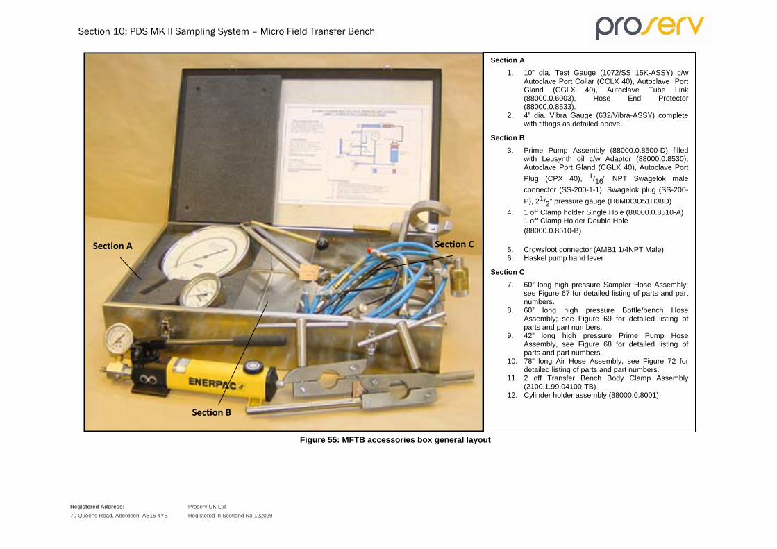
Section 10: PDS MK II Sampling System – Micro Field Transfer Bench
Registered Address: 70 Queens Road, Aberdeen, AB15 4YE
Proserv UK Ltd Registered in Scotland No 122029
Figure 55: MFTB accessories box general layout
Section A 1. 10” dia. Test Gauge (1072/SS 15K-ASSY) c/w
Autoclave Port Collar (CCLX 40), Autoclave Port Gland (CGLX 40), Autoclave Tube Link (88000.0.6003), Hose End Protector (88000.0.8533).
2. 4” dia. Vibra Gauge (632/Vibra-ASSY) complete with fittings as detailed above.
Section B 3. Prime Pump Assembly (88000.0.8500-D) filled
with Leusynth oil c/w Adaptor (88000.0.8530), Autoclave Port Gland (CGLX 40), Autoclave Port Plug (CPX 40), 1/16” NPT Swagelok male connector (SS-200-1-1), Swagelok plug (SS-200-P), 21/2” pressure gauge (H6MIX3D51H38D)
4. 1 off Clamp holder Single Hole (88000.0.8510-A) 1 off Clamp Holder Double Hole (88000.0.8510-B)
5. Crowsfoot connector (AMB1 1/4NPT Male) 6. Haskel pump hand lever
Section C 7. 60” long high pressure Sampler Hose Assembly;
see Figure 67 for detailed listing of parts and part numbers.
8. 60” long high pressure Bottle/bench Hose Assembly; see Figure 69 for detailed listing of parts and part numbers.
9. 42” long high pressure Prime Pump Hose Assembly, see Figure 68 for detailed listing of parts and part numbers.
10. 78” long Air Hose Assembly, see Figure 72 for detailed listing of parts and part numbers.
11. 2 off Transfer Bench Body Clamp Assembly (2100.1.99.04100-TB)
12. Cylinder holder assembly (88000.0.8001)
Section A
Section B
Section C

Section 10: PDS MK II Sampling System – Micro Field Transfer Bench
Registered Address: 70 Queens Road, Aberdeen, AB15 4YE
Proserv UK Ltd Registered in Scotland No 122029
MFTB pressure test procedure
1. Plug all the bulkhead fittings; fit the Test Gauge and Vibra Gauge.
2. Start the pneumatic pump stroking and bleed all the air from the system.
3. Pressurise the entire system to 15,000 p.s.i. This figure should be a maximum for the duration of the test period.
4. Close V7 and open V8 and observe the 10" Test Gauge for any indication of a pressure drop.
5. Close V9 and open V7 and observe the 10" Test Gauge for any indication of a pressure drop.
6. Close V4 and open V5 and observe the 10" Test Gauge for any indication of a pressure drop.
7. Re-pressurise the system to 15,000 p.s.i.
8 Close V10 and V11 and then open V5. At this point observe the Vibra Gauge for any indication of a pressure drop.
9. Open the sampler port (bulkhead fitting plug) and observe the Vibra Gauge. It should maintain the same pressure reading.
10. Open V11 to release the contained pressure.
This completes the pressure test.

Section 10: PDS MK II Sampling System – Micro Field Transfer Bench
Registered Address: 70 Queens Road, Aberdeen, AB15 4YE
Proserv UK Ltd Registered in Scotland No 122029
Figure 56: Schematic of Field Transfer Unit showing sample transfer into P.D.S. sample bottle.

Section 10: PDS MK II Sampling System – Micro Field Transfer Bench
Registered Address: 70 Queens Road, Aberdeen, AB15 4YE
Proserv UK Ltd Registered in Scotland No 122029
Transfer bench assembly
A. Remove the front cover by releasing the four spring clips and unscrewing the two knurled safety lugs.
B. Lift off the front cover using the handles and place to one side.
If required, the cover can be used to stabilise the unit when attached to the rear using the safety lugs.
C. Insert the swivel cylinder holder into the location point at the side of the bench and secure in place. Position the piston sample cylinder in the holder and tighten the securing screws to lock the cylinder in place.
The valve ports on the cylinder must be pointing towards the back of the bench.
D. The piston sample cylinders should be filled with transfer fluid prior to being shipped to the well site but it is advisable to check all cylinders are correctly filled prior to use.
SAFETY WARNING: The transfer lock sleeve must be fitted prior to pressurisation of the sample chamber.
E. Fit the extension arms into the two rearward facing holes at the top left and top right of the bench and Insert and secure the two body clamps. Tighten all four screws sufficiently so that most of the play has been removed, but small adjustments in position may be carried out. Fit the Sample chamber complete with Prime port nipple into the clamps and roughly line up the transfer port with the cylinder valve, see Figure 61.
Figure 57: Fitting of the sample cylinder and sample chamber
Important: check that the flow regulator has been removed.
F. Fit the airline, pressure gauge (to snubber valve), Vibra Gauge (to top bulkhead fitting), hose from the bulkhead fitting (leading from V11) and screw the transfer bench sleeve assembly into the end of the flow regulator/prime nipple assembly. Fit the other hose to the bulkhead fitting positioned next to the cylinder holder and connect it to the bottom valve on the piston sample cylinder.

Section 10: PDS MK II Sampling System – Micro Field Transfer Bench
Registered Address: 70 Queens Road, Aberdeen, AB15 4YE
Proserv UK Ltd Registered in Scotland No 122029
G. Bleed all the air out of the system. Remove the sample chamber prime port plug and crack open the prime port nipple one half turn.
WARNING: It is critical that the transfer lock sleeve is fitted before any pressure is applied to the sample chamber assembly.
H. Close V9 and V5, open the snubber valve, V10, V4, V6 and V11. Flush the transfer fluid through to the prime port nipple to remove air from the hose connection this can be done using the pump. Close the prime port nipple and open V9.
IMPORTANT: It is critical that V6 is open when operating the pump. If not, an air lock can develop causing the pump to malfunction. This results in no transfer fluid being pumped.
I. Check that V7 and V8 are closed, crack open the hose connection to the bottom valve on the piston cylinder. Again, remove air from the hose by pumping fluid through it and whilst doing so tighten the connection.
J. Crack open the connection from the pressure gauges slowly stroking the pump by hand until all the air is flushed out then tighten.
K. The system has to be pressure tested to 1,000 p.s.i. above the anticipated transfer pressure. Open valves V11, V6, V4, V10, V9, the snubber and the bottom valve on the piston sample cylinder. Close valves V7, V5, and V8. Open the air supply valve and the pump supply valve. Gradually turn up the air pressure regulator to the required pressure. When the test has been completed, bleed the pressure down by opening V5.
L. Push the ‘O’ ring protector back to expose the sample port and remove the transfer port plug (see Figure 60).
Figure 58: Exposing the sample port

Section 10: PDS MK II Sampling System – Micro Field Transfer Bench
Registered Address: 70 Queens Road, Aberdeen, AB15 4YE
Proserv UK Ltd Registered in Scotland No 122029
M. Screw in the transfer adaptor and tighten (taking care not to over-tighten). Slowly swivel the piston sample cylinder towards the transfer adaptor making sure that the port and stem are in line connect and tighten. Evacuate the air from the transfer port connection through the evacuation port of the sample cylinder. Attach the hand pump to the vacuum port via the evacuation port adaptor. Open the port by holding the evacuation port assembly with a spanner, turning the top part anti-clockwise. Open the top valve on the piston sample cylinder and evacuate the transfer section (see Figure 61).
Figure 59: Evacuation of the transfer section
N. While this transfer section is under vacuum, close the Evacuation Port Nipple and remove the hand pump.
O. Check that V7 and V5 are closed - all other valves should be open. Pressurise up the entire system to 1,000 p.s.i. above the bottom hole pressure. Shut off the air regulator and allow the pressure to stabilise. Lower the pressure in the system by slowly opening V5, observe for a kick in the pressure gauge reading as it lowers and note the pressure at which this occurs. The kick is caused by movement of the floating piston due to the presence of gas in the sample, therefore an accurate opening pressure and temperature may be recorded at this time.
This process may be repeated as required. If no opening pressure is found using this method an alternative method may be used and is described in the following paragraph
The purpose of an opening pressure is normally to check the validity of samples by comparison when multiple samples are taken from the same zone.
P. Check that V7 and V5 are closed; all other valves must be open. Pressurise the system to 1,000 p.s.i. exactly, then shut off the air regulator and allow the pressure to stabilise. Open the sampler needle valve two complete turns and observe the opening pressure increase or decrease. Allow the pressure to stabilise and take a note of the pressure and temperature of the sampler.

Section 10: PDS MK II Sampling System – Micro Field Transfer Bench
Registered Address: 70 Queens Road, Aberdeen, AB15 4YE
Proserv UK Ltd Registered in Scotland No 122029
Due to the (evacuated) lost volume of approx. 6 ml in top of the cylinder and the transfer port there will be a minor pressure drop (Opening Pressure) when the sampler needle valve is opened. This lost volume represents only 1% of the total sample volume. The pre-charge pressure of 1000 p.s.i. should compensate for this very small reduction in volume.
Q. With the sampler needle valve open, pump up the entire system to at least 1500 p.s.i. above the expected bubble point. The pressure may be seen to initially remain stable as gas goes back into the solution and the sample returns to single phase. The pump should be operated to maintain the pressure. It may be useful to note the number of strokes required to pressure up and make the sample single phase as a comparison with other samples from the same zone.
If the approximate bubble point pressure is not known, then the transfer pressure should be 25% above reservoir pressure.
R. When the pressure has remained steady for 10 minutes, the sample can be considered single phase and ready for transfer. Close V6 and V10 and open V5. Operate the pump by increasing the air pressure with the regulator to maintain a steady pump rate.
S. A pump stroke counter is incorporated on the front panel to give an indication of the progress of a transfer (600 ml is equivalent to a specific number of pump strokes). The stroke counter requires between 30-115 p.s.i. (2-8 bar) to operate correctly.
Procedures for transferring a sample via the transfer bench There are 3 different procedures proposed for transferring a sample via the transfer bench to a cylinder, as follows:
1. Closed Loop configuration
This procedure is most suited for a SPS when bubble point analysis is not measured.
a) For this method the pump stroke counter is used to monitor the progress of the transfer.
b) The valve configuration after the initial pressurisation of the system is as follows: V6, V10 and V7 are closed and then open V5. All other valves should also be open. Note that at the point the transfer is complete (using the air regulator to control the pump pressure and rate of transfer) a slight drop in gauge pressure is observed from cylinder side.
2. Open-loop configuration (for transfer systems with just 1 pressure gauge)
a) For this method the pump stroke counter and a measuring cylinder are used to monitor the progress of the sample transfer and the larger Test Gauge to monitor pressure.
b) For this method 600 ml of Water/Glycol is displaced from the cylinder into a measuring cylinder via V8. The valve configuration after the initial pressurisation of the system is as follows: Valves V5 and V9 are closed.
Valve V7 is used to control the rate of transfer as the fluid is displaced from the system. All other valves are open. The system is maintained at a constant pressure set with the air regulator to the pump. When the transfer is complete (600 ml observed in the measuring cylinder) a slight increase in gauge pressure is observed. V7 should immediately be closed to prevent the sample pressure dropping too low.
3. Open-Loop configuration (for transfer systems with two pressure gauges)
a) To monitor the progress of the sample transfer with 2 pressure gauges in line.
b) When transferring a sample using this open-loop method the 2 pressure gauges are used to monitor the transfer (one located above the snubber valve and the other on the V11 gauge manifold). As with (2) above, 600 ml of Water/Glycol is displaced from the cylinder via V7.
The valve configuration after the initial pressurisation of the system is as follows:
Valves V4 and V5 are closed all other valves are in the open position, except of V7 which should be closed initially and then used to control the rate of transfer. Transfer fluid is bled through V8 into a measuring cylinder while a constant pressure is maintained using the air regulator to control the pump pressure. When transfer is complete (600 ml observed in measuring cylinder) a slight increase in gauge pressure will be seen on the V11 manifold

Section 10: PDS MK II Sampling System – Micro Field Transfer Bench
Registered Address: 70 Queens Road, Aberdeen, AB15 4YE
Proserv UK Ltd Registered in Scotland No 122029
gauge. V7 should immediately be closed to prevent pressure drop in the sample which will be seen on the Test Gauge. A small
drop in sample pressure is not detrimental as it can be re-pressurised.
The pressure must not be allowed to fall below 1500 p.s.i. above the expected bubble point.
T. When transfer is complete the pump will stop and a sudden but slight pressure drop will be observed on the gauge.
U. Close the top valve on the sample cylinder. Close V4 so that the system volume is minimised for bubble point determination. Disconnect the transfer adaptor and remove from sampler.
V. Slacken the clamps holding the sample chamber and move it out of the way of the sample cylinder so that the cylinder it can be rotated in the holder, see Figure 62.

Section 10: PDS MK II Sampling System – Micro Field Transfer Bench
Registered Address: 70 Queens Road, Aberdeen, AB15 4YE
Proserv UK Ltd Registered in Scotland No 122029
Figure 60: Slide the sample chamber through the body clamps away from the sample cylinder.
Bubble point analysis Having transferred the sample into the transportation piston cylinder the sample can be analysed for the bubble point. In the cylinder there is an agitation device to aid the mixing of the sample and achieve equilibrium.
The sample is agitated by rotating the bottle backwards and forwards through 180o. If a pressure decrease is observed then the sample may not be in single-phase. Re-pressurise the sample and repeat agitation until a stable pressure is achieved. To apply pressure to the sample open V4 and adjust the air regulator to operate the pump.
To measure the bubble point the sample is expanded in a step wise procedure by release of a small volume of transfer fluid (2 ml) from the cylinder. This is a closed system and following each expansion and equilibrium step the pressure noted.
This is achieved using the Constant Volume Assembly (CVA), integrated into the design of the MFTB. Check that V8 is closed, then open and close V7 to allow the CVA to fill, shown by the movement of the indicator rod. The measured volume of transfer fluid is released into a graduated cylinder by opening V8 (closed again). To equilibrate the sample, rotate the cylinder in the holder (see Figure 62) and note the pressure on the Test Gauge (see Figure 63) and record the data on a volume/pressure plot (see Figure 64). This process should be repeated until sufficient data points are obtained to determine the bubble point.

Section 10: PDS MK II Sampling System – Micro Field Transfer Bench
Registered Address: 70 Queens Road, Aberdeen, AB15 4YE
Proserv UK Ltd Registered in Scotland No 122029
Figure 61: Note the sample pressure on the test gauge.
The bubble point is measured from the graph by extrapolation. The point where the two extrapolated lines intersect is the bubble point for that sample at the measured sample temperature (normally ambient), see example Figure 64.
For low pressure samples with a low GOR and a corresponding low bubble point, it may be necessary to temporarily remove the CVA return spring as the back pressure this creates may be sufficient to affect the measurement.

Section 10: PDS MK II Sampling System – Micro Field Transfer Bench
Registered Address: 70 Queens Road, Aberdeen, AB15 4YE
Proserv UK Ltd Registered in Scotland No 122029
EXAMPLE BUBBLE POINT GRAPH
1600
1700
1800
1900
2000
2100
2200
2300
2400
2500
2600
2700
2800
2900
3000
2cc Steps removed from cylinder starting on the right
Pres
sure
(psi
)
A: Formation water
B: Reservoir fluid
C: Gas
AB
C
Figure 62: Example bubble point graph

Section 10: PDS MK II Sampling System – Micro Field Transfer Bench
Registered Address: 70 Queens Road, Aberdeen, AB15 4YE
Proserv UK Ltd Registered in Scotland No 122029
Rigging down 1. To make the sample safe during transport a gas cap is created equivalent to the expansion of the
sample by approximately 10%. Sum the total volume of transfer fluid displaced from the cylinder for the bubble point measurement. Bleed off a further volume of transfer fluid through valves V7 and V8 to a total volume of fluid of approximately 60 ml. If there was no bubble point measurement then similarly remove 60 ml of transfer fluid. Agitate the sample and note the pressure and temperature. Record the pressure as the shipping pressure.
2. Close the bottom valve on the piston sample cylinder tightly - the top valve should already be closed but if not, close tight. Bleed off remaining pressure through valves V7 and V8 or V5 back to the water/glycol tank.
3. Ensure the sample chamber needle valve is open and all the valves on the transfer bench, to allow the whole system to bleed down.
4. Fit a plug to the bottom valve on the piston sample cylinder. Disconnect the transfer adaptor from the top valve and fit a plug.
5. Remove the piston sample cylinder from the transfer bench.
6. Label the sample cylinder and fill out the sampling sheet in duplicate including one copy with the cylinder.
7. Put the cylinder into its transport box ready for dispatch to the PVT laboratory.
8. The transfer fluid can be recycled from the sample chamber back into the water/glycol tank; however this is not good practise because the sample chamber displacement fluid (oil) will contaminate the water/glycol transfer fluid.
9. The best practice is to displace the transfer fluid from the sample chamber via V12 into a suitable container and discard it. This can be done using the air line provided with the transfer bench. Fit one end to the air outlet port on the front panel of the transfer bench, and the other end to the transfer port adaptor. see Figure 65.

Section 10: PDS MK II Sampling System – Micro Field Transfer Bench
Registered Address: 70 Queens Road, Aberdeen, AB15 4YE
Proserv UK Ltd Registered in Scotland No 122029
Figure 63: Using an air line to remove the transfer fluid from the sample chamber.
10. Open the sample chamber needle valve, and close V11. Fit a suitable piece of plastic tubing to the vent pipe on V12 and direct the open end into a container to receive the fluid. Use the air regulator to apply minimal pressure to the system and slowly open V12. Direct the flow of transfer fluid into an open container.
11. When all the transfer fluid is removed the sample chamber can be disconnected from the transfer bench and re-dressed as necessary.
Transfer control Absolute control and flow observation is required when transferring a sample. The latest model of the Transfer System is supplied with a second pressure gauge (15K Vibra Gauge) which is connected to a bulkhead fitting above the front panel. As a replacement for the Vibra Gauge an additional Test Gauge can be supplied on request from Proserv.
An additional Test Gauge permits the more accurate monitoring of the fluid pressure being pumped into the sample chamber against the pressure below the piston on the transport cylinder when a transfer is in progress. Any blockage in the system, which would inhibit the transfer, would be more easily detected as both gauges should indicate the balanced transfer pressure.
The second gauge is also useful in detecting an incorrect valve set-up, as this could lead to an over-pressure of the system and complete loss through rupture of the safety disc.

Section 11: PDS MK II Sampling System – MFTB Complete Parts and
Assembly Lists
Registered Address: 70 Queens Road, Aberdeen, AB15 4YE
Proserv UK Ltd Registered in Scotland No 122029
Complete parts and assembly lists for the Micro Field Transfer Bench
Figure 64: Part No. 88000.0.6001 – Constant Volume Assembly
Table 23: Constant volume assembly components list
Part No Description
88000.0.6001-1 Constant Volume Assembly Body
88000.0.6001-2 Constant Volume Assembly End Cap
88000.0.6001-3 Constant Volume Assembly Piston
88000.0.6001-4 Constant Volume Assembly Indicator Rod
86600.0.3013-6 Trigger Spring
50-014V90 O Ring (Viton 90)
50-014STDSPL Solid Split Standard PTFE BUR
Spring
Body End Cap
Piston Indicator Rod

Section 11: PDS MK II Sampling System – MFTB Complete Parts and
Assembly Lists
Registered Address: 70 Queens Road, Aberdeen, AB15 4YE
Proserv UK Ltd Registered in Scotland No 122029
Figure 65: Part No. 88000.0.8500-A-MKII – Sampler Hose Assembly
Table 24: Sampler Hose Assembly Component List
Part No. Description
88000.0.2024-3 Protection Cap
88000.0.2024-2 Transfer Sleeve
88000.0.2024-1 Transfer Coupling
88000.0.8533 Hose End Protector
86500.0.8528 Flexible Hose Adaptors (Quantity 2)
4005ST-60 Hose Assembly 60” MS Plated
CCLX40 Autoclave Collar (Quantity 2)
CGLX40 Autoclave Port Gland (Quantity 2)
50-210V90 O Ring (Viton 90) (Quantity 2)
50-210STDSPL Solid Split Standard PTFE BUR (Quantity 2)
Autoclave Collar & Gland (2off) &
Hose End Protector
Protection Cap
Transfer Sleeve
Transfer Coupling Flexible Hose Adaptor
Flexible Hose (Female Swivel) with 1/4" BSP Ends

Section 11: PDS MK II Sampling System – MFTB Complete Parts and
Assembly Lists
Registered Address: 70 Queens Road, Aberdeen, AB15 4YE
Proserv UK Ltd Registered in Scotland No 122029
Figure 66: Part No. 88000.0.8500-B – Prime Pump Hose Assembly
Table 25: Prime Pump Hose Assembly Component List
Part No. Description
88000.0.8533 Hose End Protector
BN4-4HN10K-SS Flexible Hose Adaptor 1/4BSP Male x ¼ NPT Male
88000.0.8528 Flexible Hose Adaptor
4005ST-42 Hose Assembly 42” MS Plated
AH630 Enerpac Male Coupling
CCLX40 Autoclave Collar
CGLX4 Autoclave Port Gland
Autoclave Collar & Gland
Hose End Protector
Flexible Hose Adaptor Flexible Hose Adaptor
Flexible Hose (Female Swivel) with 1/4 " BSP Ends
Enerpac Fitting

Section 11: PDS MK II Sampling System – MFTB Complete Parts and
Assembly Lists
Registered Address: 70 Queens Road, Aberdeen, AB15 4YE
Proserv UK Ltd Registered in Scotland No 122029
Figure 67: Part No. 88000.0.8500-C – Cylinder/bench hose assembly
Table 26: Cylinder/bench hose assembly component list
Part No. Description
88000.0.8533 Hose End Protector (Quantity 2)
88000.0.8528 Flexible Hose Adaptors (Quantity 2)
CCLX40 Autoclave Collars (Quantity 2)
CGLX40 Autoclave Port Gland (Quantity 2)
4005ST-60 Hose Assembly 60” MS Plated
Flexible Hose (Female Swivel) with 1/4 " BSP Ends
Hose End Protector Flexible Hose Adaptor
Autoclave Collars & Glands
Hose End Protector
Flexible Hose Adaptor
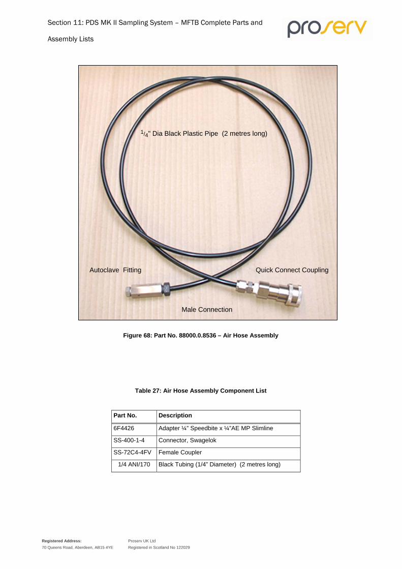
Section 11: PDS MK II Sampling System – MFTB Complete Parts and
Assembly Lists
Registered Address: 70 Queens Road, Aberdeen, AB15 4YE
Proserv UK Ltd Registered in Scotland No 122029
Figure 68: Part No. 88000.0.8536 – Air Hose Assembly
Table 27: Air Hose Assembly Component List
Part No. Description
6F4426 Adapter ¼” Speedbite x ¼”AE MP Slimline
SS-400-1-4 Connector, Swagelok
SS-72C4-4FV Female Coupler
1/4 ANI/170 Black Tubing (1/4” Diameter) (2 metres long)
1/4" Dia Black Plastic Pipe (2 metres long)
Autoclave Fitting
Male Connection
Quick Connect Coupling

Section 11: PDS MK II Sampling System – MFTB Complete Parts and
Assembly Lists
Registered Address: 70 Queens Road, Aberdeen, AB15 4YE
Proserv UK Ltd Registered in Scotland No 122029
Figure 69: Part No. 88000.0.8500-D – Prime Pump Assembly
Table 28: Prime Pump Assembly Component List
Part No. Description
SS-200-1-1 Male Connection, 1/8 Tube x 1/16 M/P
SS-200-P Hex Plug
88000.0.8530-1 Prime Pump Adaptor
CPX 40 Autoclave Port Plug
CGLX 40 Autoclave Gland
P142 Enerpac Pump
H6MIX3D51H38B Gauge, 63mm 0-6000PSI/Bar ¼”NPT Bottom Fitting
MAV2NS-1M-36MM-H ALCO ¼ NPT 6000PSI RA Valve
Gauge 0-6000PSI, 1/4 " NPT Male Connection
1/16" NPT Male Connector and Plug
Prime Port Adaptor A.E. Gland and A.E. Plug
Enerpac Pump

Section 11: PDS MK II Sampling System – MFTB Complete Parts and
Assembly Lists
Registered Address: 70 Queens Road, Aberdeen, AB15 4YE
Proserv UK Ltd Registered in Scotland No 122029
Table 29: Part No. 88000.0.0000-RS – Contingency Back Up Spares MFTB
Item Qty Part No. Description
1 1 M-HP-188-ASSY Haskel Pump Assembly
2 1 HS17179-188 Seal Kit (Haskel Pump Fluid Section)
3 1 HS17178 Seal Kit (Haskel Pump Air Drive Section)
4 3 20SM4073 20K 3-Way Angle Valve AE
5 1 20SM4072 20K 2-Way Angle Valve AE
6 2 20SM4071 20K 2-Way Straight Valve AE
7 1 CSX4600/P7375 Universal Safety Head Assembly (c/w Rupture Disc)
8 2 P-7375-CE Rupture Disc, CE Marked
9 1 B07-201-M3KG Norgren Filter Regulator
10 1 P142 Hydraulic Hand Pump
11 1 88000.0.6001 Constant Volume Assembly (c/w Seals)
12 5 50-014V90 O Ring (Seal Kit for Item 11)
12 5 50-014STD SPL Solid Split Standard PTFE BUR (Seal Kit for Item 11)
13 1 SS-4P4T1 Plug Valve
14 1 AMB1 1/4NPT Male Crowsfoot Connector
15 1 H6MIX3D51H38B Gauge, 63mm 0-6000PSI/Bar ¼”NPT Bottom Fitting
16 1 632/Vibra-ASSY 15K Vibra Gauge Assembly
17 1 1072/SS 15K-ASSY 15K Test Gauge Assembly
18 1 0495 464 Pump Stroke Counter
19 5 88000.0.8528 Flexible Hose Adaptor
20 10 50-210V90 O Ring (Seal Kit for Part No. 86600.0.2024)
20 10 50-210STDSPL Solid Split Standard PTFE BUR (Seal Kit for Part No. 86600.0.2024)
21 2 SS72N4-4FV ¼”NPT Snaptite Fem Nipple 316 SS
22 2 88000.0.8500-A-MKII Sampler Hose Assembly (60”)
23 2 88000.0.8500-C Bottle/Bench Hose Assembly (60”)
24 2 88000.0.8500-B Prime Pump Hose Assembly (42”)
25 2 88000.0.8536 Air Hose Assembly

Section 12: PDS MK II Sampling System – Single Phase
Sampler (SPS)
Registered Address: 70 Queens Road, Aberdeen, AB15 4YE
Proserv UK Ltd Registered in Scotland No 122029
Single Phase Sampler (SPS)
Introduction The Proserv SPS section added to the MK II Positive Displacement Sampler (PDS) is a development to provide high quality samples from subterranean reservoirs which are then maintained in single phase (using a nitrogen gas charge). When analysed at reservoir conditions, samples provide data vital for the economic and technical evaluation of the associated reservoir. The sampler was designed to operate in most environments and to consistently provide representative samples regardless of well fluid or hostile conditions.
Single Phase Sampler Description The SPS section is fitted to a standard MK II PDS. The sampler can be triggered by various methods, please refer to the PDS Description section on page 11 for details.
The SPS section (nitrogen chamber) is fitted between the sample chamber assembly and the air chamber assembly. The nitrogen chamber is primed with nitrogen to a pressure above the expected down-hole reservoir pressure (approximately 2000 p.s.i. above). When the sampler is at the required well depth and is triggered the well pressure displaces fluid from the sample chamber into the air chamber. The sampling process is identical for PDS and SPS until the sample is trapped in the sample chamber. The needle valve body pulls the sure lock assembly into place, locking in the sample. Nitrogen flow ports are then exposed releasing the gas pressure to act upon the top of the floating piston, which keeps the sample pressurised as it cools and shrinks during retrieval from the well.
Specifications of the SPS Nitrogen Chamber Volume 450 ml (approximately) 28 cu in.
Maximum W.P. 1034 bar 15,000 p.s.i.
Maximum W.T. 180 oC 356 oF
Length (Single Phase Section) 1370 mm 4 ft 6 in.
Length (Complete Sampler) 5054 mm 16 ft 7 in.
Outside Diameter 42.8 mm 1 11/16 in.
Weight (Single Phase Section) 6 kg 13.2 lb
Weight (Complete Sampler) 34 kg 74.8 lb
Main features of the SPS • The ability to operate in high H2S, CO2 and high G.O.R. wells.
• Double seal on all well pressure exposed joints.
• Fast redress.
• Rugged construction with minimal components.
• Lloyd's Register of Shipping (Industrial Services Division) design approval.
Applications of the SPS • Organic scale (asphaltenes, resins, waxes).
• Formation water.
• Near critical reservoir fluids.
• Gas/Condensate reservoirs.

Section 12: PDS MK II Sampling System – Single Phase
Sampler (SPS)
Registered Address: 70 Queens Road, Aberdeen, AB15 4YE
Proserv UK Ltd Registered in Scotland No 122029
Safe handling procedures
Although the items used in construction employ designs, materials and proprietary components calculated and tested to withstand maximum pressures, certain standard safety considerations should be made during testing and operation.
During sampling (SPS operation)
The design and construction of the SPS section is made to meet the requirements for single-phase sampling. The sampler utilises a charge of nitrogen held under pressure by a sliding sleeve arrangement. When the nitrogen pressure is activated for release by the rod connector this further pressurises the sample by contact with the floating piston.
The materials used in construction of the SPS need to meet the requirement of pressure rating and corrosion resistance. To avoid thread galling, certain crossover connections are manufactured in an alternative material considered suitable for expected pressure and corrosion exposure.
The nitrogen pressure at surface temperature will increase on exposure to the down hole well temperature. The integrity of the nitrogen chamber is designed to withstand this increase. The SPS section can be tested separately, charging up the nitrogen chamber and observing for leaks.
Some components that are used (fittings, hoses, connections, pumps) are of proprietary manufacturer and some special plugs/fittings are manufactured from 17-4PH stainless steel. The design considerations and depth of engagement of threaded parts are based on standard high-pressure hydraulic fittings used in similar industrial applications.
Care must be taken when testing the sampler to ensure that all seals and fittings are as original and suitable for service and component parts have been checked and periodically pressure tested. The SPS section should be set up in an area specially set aside for the purpose where only technicians involved on the operation have access. All safety guidelines relevant to pressure testing should apply.
The above should also apply when the sampler is retrieved from the well with a high-pressure sample in the sample chamber. Although the sample chamber tube is designed to contain pressures internally, the sampler should be handled with care avoiding any mechanical shock whilst the system is under pressure.
Before commencing the transfer process the sure lock assembly should be checked for engagement. This is critical as serious injury could result and/or the loss of sample during transfer. A transfer lock sleeve is provided as an additional safety measure for retaining the pressurised sample and this is fitted as replacement to the nose cone before transfer and to give access to operate the needle valve.
The SPS section should be left connected to the sample chamber assembly and must only be disconnected immediately before transfer, therefore maintaining contact between sample and the nitrogen charge and compensating any further pressure change due to temperature change during transit.
The nitrogen chamber must be isolated from the sample chamber and the gas pressure must be bled down before removing the SPS section.

Section 13: PDS MK II Sampling System – Running the SPS
Registered Address: 70 Queens Road, Aberdeen, AB15 4YE
Proserv UK Ltd Registered in Scotland No 122029
Running the SPS
Single Phase section
Withdraw the Single Phase Section from its transit box.
It is assumed that the sample chamber/air chamber (MK II PDS) have been prepared as required for a run, see MK II PDS section.
Unscrew the sure lock assembly from the connector protection sub, push out the split collets and remove the securing screw. Next, squeeze the split collets together and insert them into the sure lock retaining lugs collet/tool, see Figure 72.
Figure 70: Inserting the sure lock split collets into the retaining lugs.
The complete unit can be inserted into the front end (Male Thread Side) of the sure lock sub. Push the split collets into the sure lock sub and remove the sure lock retaining lugs collet/tool, see Figure 73. Align the Split Collets as shown in Figure 74 and insert the securing screw.
Unscrew the nose cone from the sample chamber and replace it with the sure lock sub. Screw on the Sure Lock Sub until the securing screw can be located with the threads in the Needle Valve Body. Secure the Split Collets to the Needle Valve Body by tightening up the screw. Fully tighten the Sure Lock Sub.
Make sure that the small radius in the bore and the securing pin are aligned.

Section 13: PDS MK II Sampling System – Running the SPS
Registered Address: 70 Queens Road, Aberdeen, AB15 4YE
Proserv UK Ltd Registered in Scotland No 122029
Figure 71: Inserting the sure lock collets into the sure lock sub
Tighten the sure lock sub onto the sample chamber and replace the nose cone. To complete the assembly of the sample chamber follow the procedures in the PDS section.
Figure 72: Sure lock collet alignment.
Unscrew the connector protection sub from the SPS sub assembly. Check that the stinger assembly is fully extended. This can be checked by screwing the stinger extractor tool into the stinger assembly and pulling. The bottom of the taper should be flush with the front face, see Figure 75.

Section 13: PDS MK II Sampling System – Running the SPS
Registered Address: 70 Queens Road, Aberdeen, AB15 4YE
Proserv UK Ltd Registered in Scotland No 122029
Figure 73: Checking the stinger assembly is fully extended
Once this has been done replace the connector protection sub, as this will protect the stinger assembly from any damage or movement.
The nitrogen chamber can now be pressurised with nitrogen gas to the required pressure.
The recommended pressure is approximately 2000 p.s.i. above the expected reservoir pressure. This over pressurisation is to compensate for the sample volume shrinkage as it cools during the retrieval to surface. To prime with nitrogen refer to the illustration of the Single Phase Section valves as shown in Figure 76.
Figure 74: Set up the SPS section ready for priming with nitrogen.
Connect the nitrogen gas supply via the gas booster pump to the nitrogen prime port. Valve V1 should be closed and V2 open.
Following a redress it will be necessary to purge the nitrogen chamber with gas:
1. Evacuate the nitrogen chamber with a vacuum pump or purge by pressurising to approximately 3000 p.s.i. 2-3 times.
2. Pressurise the nitrogen chamber to the required pressure and close valve V1 and V2. Remove the high-pressure line and replace the nitrogen prime port plug.
For Single Phase Sampling the position of the flow regular is changed, the MK II PDS sampler flow regulator/prime nipple assembly is surplus to requirements and should therefore be removed. The flow regulator placement is now positioned at the top of the nitrogen chamber.
Prime Port
Valve (V1)
Valve (V2)
Nitrogen Prime Port, opposite V2
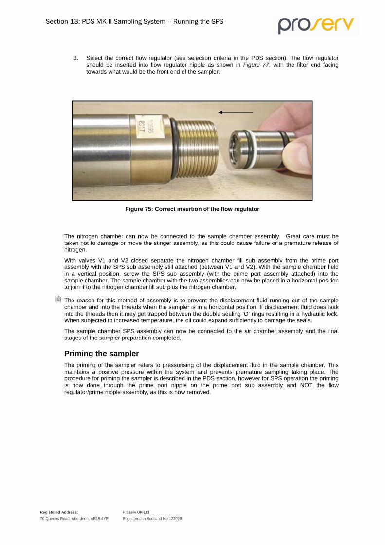
Section 13: PDS MK II Sampling System – Running the SPS
Registered Address: 70 Queens Road, Aberdeen, AB15 4YE
Proserv UK Ltd Registered in Scotland No 122029
3. Select the correct flow regulator (see selection criteria in the PDS section). The flow regulator should be inserted into flow regulator nipple as shown in Figure 77, with the filter end facing towards what would be the front end of the sampler.
Figure 75: Correct insertion of the flow regulator
The nitrogen chamber can now be connected to the sample chamber assembly. Great care must be taken not to damage or move the stinger assembly, as this could cause failure or a premature release of nitrogen.
With valves V1 and V2 closed separate the nitrogen chamber fill sub assembly from the prime port assembly with the SPS sub assembly still attached (between V1 and V2). With the sample chamber held in a vertical position, screw the SPS sub assembly (with the prime port assembly attached) into the sample chamber. The sample chamber with the two assemblies can now be placed in a horizontal position to join it to the nitrogen chamber fill sub plus the nitrogen chamber.
The reason for this method of assembly is to prevent the displacement fluid running out of the sample chamber and into the threads when the sampler is in a horizontal position. If displacement fluid does leak into the threads then it may get trapped between the double sealing ‘O’ rings resulting in a hydraulic lock. When subjected to increased temperature, the oil could expand sufficiently to damage the seals.
The sample chamber SPS assembly can now be connected to the air chamber assembly and the final stages of the sampler preparation completed.
Priming the sampler The priming of the sampler refers to pressurising of the displacement fluid in the sample chamber. This maintains a positive pressure within the system and prevents premature sampling taking place. The procedure for priming the sampler is described in the PDS section, however for SPS operation the priming is now done through the prime port nipple on the prime port sub assembly and NOT the flow regulator/prime nipple assembly, as this is now removed.

Section 13: PDS MK II Sampling System – Running the SPS
Registered Address: 70 Queens Road, Aberdeen, AB15 4YE
Proserv UK Ltd Registered in Scotland No 122029
Selecting the clock for mechanical operation The clock selection, setting and fitting procedure is described in the PDS section.
Nitrogen gas release to transmit pressure to the sample chamber On completion of the set up procedures, the penultimate operation before running the SPS is to release the nitrogen pressure, opening the route through the SPS nitrogen chamber fill sub and SPS prime port assembly to act against the stinger and nitrogen stem, by opening valves V1 and V2. The sampler is now ready to run in the well and can be carried to the wellhead. The final requirement for a successful run is to release the setting screw (see page 44, Figure 39) immediately prior to the sampler being lifted into the lubricator for the run.
Periodic workshop checks 1. Inspect the rear of the stinger sealing diameters for internal and external marking that may cause
leaking. If damage is observed then the unit must be replaced.
2. Inspect the sure lock collets and spring for evidence of wear, for example, rounding of the edges on the collets, if there is evidence of wear on the collets they may fail to hold resulting in loss of sample and possible injury to personnel.
3. Inspect the nitrogen release stem for damage also check the metal-metal seal on the mating part with the prime port sub assembly. If damage is observed then the parts must be replaced.
4. Inspect and test all valves and sealing parts for evidence of damage and wear (metal-metal seats and sealing bores). If any damage is observed then the parts must be replaced.
Function test and simulated well test of a MK II PDS/SPS sampler Proserv engineers use the procedure described as a final functional check before packing and despatching the sampler. This test has been introduced to function test all internal assemblies and it involves the use of compressed air and nitrogen as well as the recommended Synthetic Displacement Oil.
1. Completely assemble the Single Phase Section as described previously. Shut valve V1 and open valve V2. Prime the nitrogen chamber to 2500 p.s.i. and put the unit to one side.
2. Fill the sample chamber with synthetic displacement oil as per standard as described in the PDS section. Screw all three sections together (the sample chamber, Single Phase Section and the air chamber assembly.
A flow regulator is not necessary for this test.
3. Remove the nose cone and replace it with the sure lock assembly.
The sure lock assembly should be set as discussed previously. It is very IMPORTANT to make sure that the sure lock sub is screwed tightly onto the sample chamber.
4. Screw the extra long well test simulator onto the sure lock sub. It is IMPORTANT to ensure that the well test simulator is only screwed up by hand and then backed off a quarter of a turn. Fit the trigger mechanism, container tube and clock with elapse time set and top nipple.
Fit the trigger mechanism, container tube and clock with elapse time set and top nipple.

Section 13: PDS MK II Sampling System – Running the SPS
Registered Address: 70 Queens Road, Aberdeen, AB15 4YE
Proserv UK Ltd Registered in Scotland No 122029
Proserv engineers use a demonstration sampler clock that has no timing mechanism which is operated manually by rotating the knurled handle of the device, which in turn revolves the slotted cone, see reference in PDS section. If this item is required it can be purchased from Proserv.
5. Back off the setting screw and prime the sampler to 1000 p.s.i. Open V1and V2.
6. Pressure up the sample chamber through the well test simulator to 1000 p.s.i. With the pump of the Transfer Bench set to maintain a steady 1000 p.s.i. rotate the clock (if a demonstration clock is used) or pull out the clock if a standard unit is used. The sampler will then operate and simulate a sample being taken (in this case the water/glycol from the Transfer Bench).
7. Once the sample run is completed, bleed down any pressure in the well test simulator and then remove the unit.
IMPORTANT: If the well test simulator feels tight when being unscrewed, this may be because the sure lock sub is being unscrewed with it. Great care must be taken if this is the case. The pressure in the sample chamber must be bled off through the nitrogen prime plug, checking that valve V1 and valve V2 are shut before removing the plug. Open valve V1 slowly and bleed off the pressure. The test will have to be repeated.
8. With the well test simulator removed, check that the Posi-Lock Pin is in place and check that the sure lock collets have sprung out and are in place. It is good practise to fit a transfer lock sleeve during this function test.
9. The sample (glycol/water mix) must be bled from the sample chamber. To do this, slide back the ‘O’ ring sleeve, remove the transfer port plug, screw in the transfer adaptor with a plastic tube attached and finally open the needle valve. This allows the nitrogen to push the sample into a container.
10. Shut valve V2 (shutting off the nitrogen chamber). Next shut valve V1 and open the nitrogen prime port plug. Slowly open valve V1 and release the nitrogen gas from the sample chamber. All sections can be dismantled and cleaned as per standard practice and as described in previous sections of this manual.
Test Certificate for PDS/SPS As well as the function test performed in the previous section, the information and individual tests described below form part of the PDS/SPS release certificate.
1. Parts are assembled complete as per general arrangement drawings.
2. The correct seating of all valves, nipples and plugs that have metal-to-metal seating are checked
3. Pressure test at 10,000 p.s.i. with valve V1 and valve V2 closed.
4. Pressure test at 10,000 p.s.i. the nitrogen release stem and stinger assembly.
5. Pressure test the nitrogen chamber assembly (with nitrogen pressure held for a duration of 10 minutes).
6. Pressure test at 10,000 p.s.i. with valve V1 and valve V2 open, the prime port nipple/plug open and closed and the nitrogen prime port plug closed.
7. The correct position and function of the sure lock assembly is checked.
8. A function test of the SPS section with the PDS in line to observe the gas crossover timing. This function test is described in more detail in the previous section.
9. Drain and clean the sampler, then stamp with the serial number and store.
10. All of the above are witnessed by the Proserv Quality Control Inspector (the details of all the above are described in this manual).

Section 14: PDS MK II Sampling System – SPS – Checks
to Prevent Failure
Registered Address: 70 Queens Road, Aberdeen, AB15 4YE
Proserv UK Ltd Registered in Scotland No 122029
SPS - Checks to prevent a sampler failure
1. Check: The split collets on the sure lock assembly are free to spring open while attached to the needle valve body by the securing screw.
Reason: Loss of sample will occur, due to the split collets not opening and engaging into their recess, therefore, allowing the needle valve body assembly/floating piston assembly to be pushed back into their original position, by the nitrogen gas pressure when this is released, opening up the inlet ports. It should also be noted that in the process the Posi-Lock Pin will be sheared.
2. Check: The stinger assembly is in the correct position.
Reason: If the stinger assembly is too far forward the flow of the displacement fluid will be prevented and the sampler will not operate.
3. Check: Both the valve stems on the nitrogen chamber assembly and the prime port sub assembly are holding pressure and are not leaking past the ‘O’ rings or metal/metal seats.
Reason: Complete loss or low nitrogen pressure below the expected well pressure resulting in a sample not in single phase.
4. Check: Ths sure lock collets are in good condition i.e. the edges are not rounded off as they may not engage properly.
Reason: See item 1.
5. Check: Both the valve stems on teh nitrogen chamber sub assembly and the prime port sub assembly have been opened before the sampler is run into the well.
Reason: There will be no communication between the nitrogen chamber and the sample chamber resulting in a sample that is not in single phase.
6. Check: The nitrogen chamber is primed to the required pressure.
Reason: If the nitrogen pressure is too low this will result in a sample which is not in single phase.
7. Check: For damage or scratch marks on the stinger assembly sealing diameters.
Reason: The ‘O’ rings on the nitrogen release stem could be damaged resulting in premature release of the nitrogen.
8. Check: The nitrogen release stem is not bent before assembly.
Reason: The nitrogen release stem could damage the bore of the stinger assembly resulting in ‘O’ ring failure and premature release of the nitrogen.
9. Check: The nitrogen release stem has been tightened properly in the prime port sub assembly.
Reason: Nitrogen gas will leak into the sample chamber prematurely. This causes a build up of nitrogen gas in the displacement fluid, when the sampler is triggered. The nitrogen gas in the air chamber will create too high a back pressure. The back pressure will prevent the sampler from closing resulting in loss of sample.

Section 15: PDS MK II Sampling System –MFTB Single Phase
Transfer
Registered Address: 70 Queens Road, Aberdeen, AB15 4YE
Proserv UK Ltd Registered in Scotland No 122029
Micro Field Transfer Bench Single Phase Sample transfer
Introduction to SPS transfer The transfer of a single phase sample is very similar to the transfer method described previously for a PDS sample. There are, however, a few important differences and great care must be observed. This section has been written so as to avoid any confusion. The specifications described in the PDS MKII MFTB Section apply except for the attachment of a different transfer sleeve coupling to the sampler hose specific for SPS and to connect to the SPS prime port sub assembly.
Safe handling procedures Important checks need to be carried out when the sampler reaches the surface. The position of the Posi-Lock Pin should be checked and the transfer lock sleeve installed as soon as possible.
IMPORTANT: The sure lock assembly must be fitted when the single phase section is used.
WARNING: The transfer lock sleeve must be fitted to the sure lock sub as, it provides additional safety during sample transfer and secures the sure lock split collet against failure.

Section 15: PDS MK II Sampling System –MFTB Single Phase
Transfer
Registered Address: 70 Queens Road, Aberdeen, AB15 4YE
Proserv UK Ltd Registered in Scotland No 122029
Figure 76: Part No. 86600.SP.0.2024 – Transfer Sleeve Coupling Assembly
Table 30: Transfer Sleeve Coupling Assembly Components List
Part No. Description
86600.SP.0.2024-1 Transfer Coupling
86600.SP.0.2024-2 Transfer Sleeve
86600.SP.0.2024-3 Protection Cap
50-012V90 O Ring (Viton 90) (Quantity 2)
50-012STDSPL Solid Split Standard PTFE BUR (Quantity 2)
O Rings (Viton 90) Back Up Ring (PTFE)
Transfer Coupling
Transfer Sleeve
Protection Cap
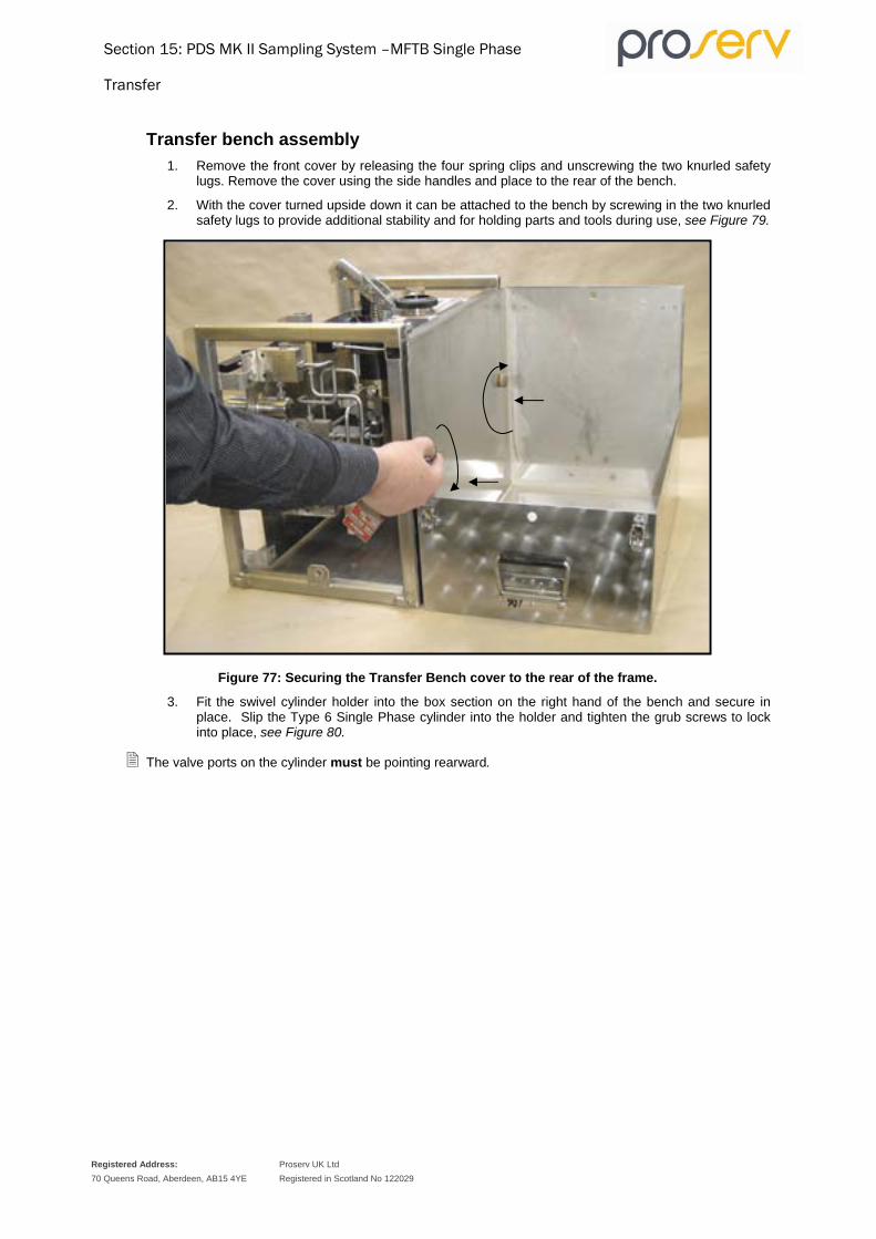
Section 15: PDS MK II Sampling System –MFTB Single Phase
Transfer
Registered Address: 70 Queens Road, Aberdeen, AB15 4YE
Proserv UK Ltd Registered in Scotland No 122029
Transfer bench assembly 1. Remove the front cover by releasing the four spring clips and unscrewing the two knurled safety
lugs. Remove the cover using the side handles and place to the rear of the bench.
2. With the cover turned upside down it can be attached to the bench by screwing in the two knurled safety lugs to provide additional stability and for holding parts and tools during use, see Figure 79.
Figure 77: Securing the Transfer Bench cover to the rear of the frame.
3. Fit the swivel cylinder holder into the box section on the right hand of the bench and secure in place. Slip the Type 6 Single Phase cylinder into the holder and tighten the grub screws to lock into place, see Figure 80.
The valve ports on the cylinder must be pointing rearward.

Section 15: PDS MK II Sampling System –MFTB Single Phase
Transfer
Registered Address: 70 Queens Road, Aberdeen, AB15 4YE
Proserv UK Ltd Registered in Scotland No 122029
Figure 78: Secure the cylinder into the swivel holder.
4. It should be noted that in preparation the Type 6 piston sample cylinder must be filled with transfer fluid and primed with nitrogen gas to approximately 1000 p.s.i. (minimum) above the expected well pressure.
If it is not possible, then preparation can be done while the sampler is sampling, or at any other convenient time on site.
SAFETY WARNING: As mentioned in the safe handling procedures section, it is advisable to check that the transfer lock sleeve has been fitted.
5. Insert the two body clamps into the extension arms and insert them into the two rearward facing holes at the top left and top right of the bench frame.
Tighten all four screws sufficiently so that most of the play has been removed, but adjustment is possible.
Before the sampler has been separated from the air chamber bleed pressure from Prime Port Nipple, if, it is suspected that 'O' ring failure may have occurred and high pressure nitrogen has passed through to the air chamber, there is a safety plug fitted to the air chamber to release the pressure (see Figure 81).
6. The air chamber assembly can now be separated from the Single Phase Section/sample chamber assembly and put aside, see Figure 81.

Section 15: PDS MK II Sampling System –MFTB Single Phase
Transfer
Registered Address: 70 Queens Road, Aberdeen, AB15 4YE
Proserv UK Ltd Registered in Scotland No 122029
Figure 79: Separation of the air chamber.
7. Valves V1 and V2 on the Single Phase Section must be kept open until just before transfer. This maintains contact of the sample with the nitrogen pressure to effect any further changes in the sample due to the ambient temperature.
8. With the transfer bench and sample cylinder set up, the Single Phase Section can be separated from the sample chamber assembly.
Close valves V1 and V2 and slowly bleed off the nitrogen from between the valves through the nitrogen prime port plug. The sampler can now be separated at the connection between the nitrogen chamber fill sub assembly and the prime port sub assembly, see Figure 82.
Figure 80: Separation of the sample chamber from the nitrogen chamber
9. Fit the sample chamber assembly complete with SPS sub assembly and prime port sub assembly in the clamps of the transfer bench.
10. Next remove the nose cone and fit the transfer lock sleeve, see Figure 83.
Pressure release plug

Section 15: PDS MK II Sampling System –MFTB Single Phase
Transfer
Registered Address: 70 Queens Road, Aberdeen, AB15 4YE
Proserv UK Ltd Registered in Scotland No 122029
Figure 81: Fitting the transfer lock sleeve
The air chamber plug retaining ring extractor can be used to screw in the transfer lock sleeve.
There are four holes running through the transfer lock sleeve, this is so that one of them can be aligned to access the needle valve stem in the needle valve body, see Figure 84.
Figure 82: Transfer lock sleeve alignment to access the needle valve stem.
11. A special transfer sleeve coupling must be fitted to the sampler transfer hose and screwed into the prime port assembly (see Figure 85).

Section 15: PDS MK II Sampling System –MFTB Single Phase
Transfer
Registered Address: 70 Queens Road, Aberdeen, AB15 4YE
Proserv UK Ltd Registered in Scotland No 122029
Figure 83: Connection of the transfer sleeve coupling.
11. Approximate alignment of the transfer port with the valve port of the cylinder.
12. Fit the airline supply, pressure gauge (to the snubber valve), Vibra Gauge (to top bulkhead fitting), hose from bulkhead fitting (leading from VII) to the transfer sleeve coupling assembly. Fit the second hose to the bulkhead fitting at the rear of the bench, next to the cylinder holder. Connect the other end of the hose to the bottom valve on the Type 6 piston sample cylinder.
13. Before proceeding with the transfer air must be bled out of the connecting hoses and other parts of the system. Crack open the connection from the transfer sleeve coupling assembly and flexible hose. Close V9, V5 and open the snubber valve, V10, V4, V6 and V11. With a slow pump rate, flush the transfer fluid through the connection until no air is present, hand tighten the connection and then open V9.
It is critical at all times that V6 is open when the pump is operated, if not an airlock will develop causing the pump to malfunction resulting in no transfer fluid being pumped.
14. Repeat the procedure for the hose connection to the sample cylinder.
15. Crack open the connections of the pressure gauges and similarly flush through transfer fluid until free of air.
16. Pressure test the system to 1,000 p.s.i. above the anticipated transfer pressure. Open V11, V6, V4, V10, V9, snubber valve and the bottom valve on the piston sample cylinder. Close V7, V5 and V8. Open the air supply valve and the pump supply valve. Slowly screw down the air pressure regulator to operate the pump and raise the pressure to that required, alternatively raise the pressure manually with the pump lever.
When the test has been completed bleed the pressure down by opening V5 or through V7 and V8.
17. Using a small screwdriver carefully push back the ‘O’ ring Protector to expose the sample port and remove the transfer port plug, see Figure 86.

Section 15: PDS MK II Sampling System –MFTB Single Phase
Transfer
Registered Address: 70 Queens Road, Aberdeen, AB15 4YE
Proserv UK Ltd Registered in Scotland No 122029
Figure 84: Push back the ‘O’ ring protector.
18. Carefully screw in the transfer adaptor and just hand tighten against the ‘O’ ring compression. Swivel the sample cylinder towards the transfer bench, making sure that the port and stem are in line and the threads make up correctly, make the connection and the then tighten with spanners.
19. Next, evacuate the air from the top of the cylinder and the transfer adaptor through the evacuation port on top of the cylinder using the vacuum hand pump. Attach the tubing of the pump to the Evacuation Adaptor fitted to the Evacuation port nipple and open the port by holding the body of the assembly with a ring spanner and turning the top part anti-clockwise. Open the valve on the cylinder and evacuate the transfer section, see Figure 87. When maximum vacuum is achieved, close the evacuation port.

Section 15: PDS MK II Sampling System –MFTB Single Phase
Transfer
Registered Address: 70 Queens Road, Aberdeen, AB15 4YE
Proserv UK Ltd Registered in Scotland No 122029
Figure 85: Evacuation of the transfer system.
20. Check that V7 and V5 are closed; all other valves on the transfer bench should be in the open position. Pressurise up the system to 2,000 p.s.i. above the bottom hole pressure, and allow the pressure to stabilise. Isolate the pump. Open V1 on the sampler and record the opening pressure.
21. Open the sampler needle valve two complete turns and observe the opening pressure. Record the opening pressure and approximate sample temperature.
There will be a very slight effect on the system pressure because of the evacuated volume of the transfer system adaptor and top of the cylinder (approximately 6 ml). The volume represents <1% of the sample volume and should not be significant.
The system pressure must not be allowed to drop below the well pressure as this could take the sample out of single phase sample.
22. Re-pressurise the system to 2000 p.s.i. above the well pressure leaving the pump active to maintain this set pressure during transfer. Close V6, V10 and open V5.
Operate the pump by screwing down on the air pressure regulator to maintain a steady pump rate. A pump stroke counter is incorporated on the transfer bench panel. The counter can be used to give an approximate indication of the progress of the transfer (600 ml will be equivalent to a specific number of pump strokes. A pressure of 2-8 bar is required for the stroke counter to operate correctly.
23. The recommended procedure for transferring a single phase sample is the closed loop method, as described in the PDS section.

Section 15: PDS MK II Sampling System –MFTB Single Phase
Transfer
Registered Address: 70 Queens Road, Aberdeen, AB15 4YE
Proserv UK Ltd Registered in Scotland No 122029
The Closed Loop method is the most suited when bubble point analysis is not required, but of course no bubble point analysis should be done with a single-phase sample if the sample integrity is to be maintained.
24. When transferring using the closed loop method, the valve configuration (after the initial pressurisation) of the system should be as follows:
Ensure V6, V10 and V7 are closed then open V5. All other valves must be in the open position.
When the transfer is complete (using the air regulator to control the rate of transfer) a slight drop in gauge pressure will be observed. It is critical that the pressure does not fall below the well pressure.
25. On the completion of transfer close the top valve on the piston sample cylinder and the needle valve on the sampler. Disconnect the transfer adaptor. Slide the sample chamber through the body clamps away from the cylinder to allow better access to the cylinder, see Figure 88 showing a 10,000 p.s.i. single phase cylinder in use.
Figure 86: Move the sample chamber away from the cylinder.

Section 15: PDS MK II Sampling System –MFTB Single Phase
Transfer
Registered Address: 70 Queens Road, Aberdeen, AB15 4YE
Proserv UK Ltd Registered in Scotland No 122029
Rigging down after transfer 1. With the sampler isolated, shut valve V4 on the transfer bench.
2. Open the nitrogen cylinder valve on the Type 6 cylinder (the valves are colour coded this valve by yellow and the end cap stamped to identify the valves, see Figure 89 illustrating the identification on a 15K cylinder. This will release the nitrogen to make contact with what remains of the transfer fluid and thereby maintaining the sample single phase.
Figure 87: Type 6 Cylinder valve identification.
Figure 89 shows the Type 6 cylinder valve identification stamped on the end cap.
3. Observe the pressure on the gauge; the pressure should still read 2000 p.s.i. above well pressure. Close the bottom cylinder fill/transfer valve (this valve is colour coded red), see Figure 89.
4. Shut off the air supply to the pump and bleed down the pressure in the transfer bench, by, opening valve V4 and slowly opening valves V5 and V6. This will allow the transfer fluid to bleed back into the reservoir.
5. All the valves on the Type 6 cylinder are anti-tamper proof and are operated by a special anti-tamper proof key. This tool is supplied with each cylinder (see Figure 90, illustrating the valve key in use with a 15,000 p.s.i. cylinder).

Section 15: PDS MK II Sampling System –MFTB Single Phase
Transfer
Registered Address: 70 Queens Road, Aberdeen, AB15 4YE
Proserv UK Ltd Registered in Scotland No 122029
Figure 88: Diagram showing the anti-tamper proof valve key.
6. Remove the hose and connections from the bottom valve of the cylinder, then re-fit the plugs to both top and bottom valves.
7. Remove the sample cylinder from the transfer bench.
8. Screw on the valve protection caps, label the cylinder and fill out the sampling sheet in duplicate. Include one of the duplicate sampling sheets with the cylinder in the transportation box.
9. Put the piston sample cylinder into its transport box ready for dispatch to the PVT laboratory.
10. It is advisable to dispose of the transfer fluid from the sample chamber, as it will be contaminated with displacement fluid (oil). This can be done through V12 and using a special air line supplied with the transfer bench. Connect the air line to the air outlet port on the front panel of the transfer bench and the other end to the transfer adaptor (see Figure 65 in the PDS section). Attach a piece of plastic tube to the outlet on V12. Open the sample chamber needle valve. And check V10 is closed, keeping the pump supply valve closed and open the air supply valve. Direct the flow of transfer fluid into a suitable container.
11. The sample chamber can be disconnected from the transfer bench and re-dressed.

Section 15: PDS MK II Sampling System –MFTB Single Phase
Transfer
Registered Address: 70 Queens Road, Aberdeen, AB15 4YE
Proserv UK Ltd Registered in Scotland No 122029
Transfer control
Absolute control and flow observation is required when transferring a sample. The latest model of the Transfer System is supplied with a second pressure gauge (15K Vibra Gauge) which is connected to a bulkhead fitting above the front panel. As a replacement for the Vibra Gauge an additional Test Gauge can be supplied on request from Proserv.
An additional Test Gauge permits the more accurate monitoring of the fluid pressure being pumped into the sample chamber against the pressure below the piston on the transport cylinder when a transfer is in progress. Any blockage in the system, which would inhibit the transfer, would be more easily detected as both gauges should indicate the balanced transfer pressure.
The second gauge is also useful in detecting an incorrect valve set-up, as this could lead to an over-pressure of the system and complete loss through rupture of the safety disc.

Section 16: PDS MK II Sampling System – Servicing the Single
Phase Section
Registered Address: 70 Queens Road, Aberdeen, AB15 4YE
Proserv UK Ltd Registered in Scotland No 122029
Servicing the single phase section It is important to check the condition of the 'O' ring seals and their back-up rings. It may not be necessary to replace them if they are in good condition. If there is any doubt in any operator's mind, the seals should be replaced.
The upper section of the Single Phase Section has already been disconnected before transfer. The nitrogen chamber/tube assembly, flow regulator sub and nitrogen chamber fill sub assembly should be connected as a complete assembly, (see Figure 91).
Figure 89: Upper part of the single-phase section.
It should be noted that the flow regulator must be removed from the flow regulator sub. Fit the flow regulator extractor into the small thread on the end of the flow regulator. If the flow regulator cannot simply be pulled from the housing, then use a spanner on the nut in a clockwise direction, this will draw out the unit from its housing to a point were it can be pulled free, (see Figure 92).
Figure 90: Removing the flow regulator with the extractor tool.
If the nitrogen chamber assembly needs to be redressed, then the nitrogen must be bled from the chamber. Open valve V2 and release the pressure. Unscrew the flow regulator nipple and redress. Screw in the air chamber plug extractor, pull out the nitrogen chamber nipple and slip the retaining fork into position. This prevents the nitrogen chamber tube assembly springing back into the nitrogen chamber, (see Figure 93).
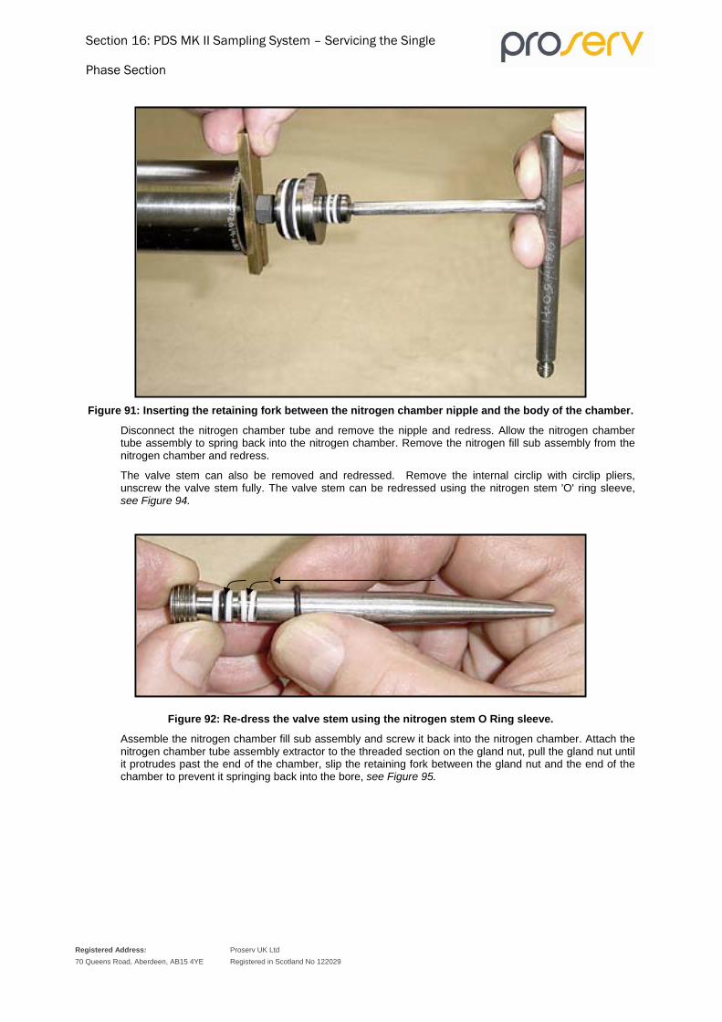
Section 16: PDS MK II Sampling System – Servicing the Single
Phase Section
Registered Address: 70 Queens Road, Aberdeen, AB15 4YE
Proserv UK Ltd Registered in Scotland No 122029
Figure 91: Inserting the retaining fork between the nitrogen chamber nipple and the body of the chamber.
Disconnect the nitrogen chamber tube and remove the nipple and redress. Allow the nitrogen chamber tube assembly to spring back into the nitrogen chamber. Remove the nitrogen fill sub assembly from the nitrogen chamber and redress.
The valve stem can also be removed and redressed. Remove the internal circlip with circlip pliers, unscrew the valve stem fully. The valve stem can be redressed using the nitrogen stem 'O' ring sleeve, see Figure 94.
Figure 92: Re-dress the valve stem using the nitrogen stem O Ring sleeve.
Assemble the nitrogen chamber fill sub assembly and screw it back into the nitrogen chamber. Attach the nitrogen chamber tube assembly extractor to the threaded section on the gland nut, pull the gland nut until it protrudes past the end of the chamber, slip the retaining fork between the gland nut and the end of the chamber to prevent it springing back into the bore, see Figure 95.

Section 16: PDS MK II Sampling System – Servicing the Single
Phase Section
Registered Address: 70 Queens Road, Aberdeen, AB15 4YE
Proserv UK Ltd Registered in Scotland No 122029
Figure 93: Inserting the retaining fork between the gland nut and chamber body.
Unscrew the extractor and replace the nitrogen chamber nipple. Screw in the air chamber plug extractor, pull slightly, then slip out the retaining fork and allow the nipple to spring back into the nitrogen chamber. Screw back the flow regulator sub.
The SPS sub assembly and the prime port sub assembly can be unscrewed from the sample assembly. The complete assembly is illustrated in Figure 96.
Figure 94: SPS sub assembly and prime port sub assembly (complete)
When the nitrogen is released into the sample chamber, the end 'O' ring and back-up ring on the nitrogen release stem may be damaged and invariably needs to be replaced, this is to be expected. Before attempting to unscrew the SPS sub assembly from the prime port sub assembly, the following steps need to be carried out.
Screw the stinger extractor tool into the stinger front thread fully, see Figure 97, and gently pull the stinger forward, if this is possible. If the stinger assembly cannot be moved in this way then unscrew the SPS sub assembly from the prime port assembly (very slowly), see Figure 98.

Section 16: PDS MK II Sampling System – Servicing the Single
Phase Section
Registered Address: 70 Queens Road, Aberdeen, AB15 4YE
Proserv UK Ltd Registered in Scotland No 122029
Figure 95: Preparing to pull the stinger with the stinger extractor tool
Figure 96: As illustrated, slowly unscrew the SPS sub from the prime port assembly.
This will gently ease the stinger assembly away from the nitrogen release stem. As both of these items are critical to the function of the SPS, inspect them for any damage or wear.
When the SPS sub assembly is separated from the prime port sub assembly, be careful not to damage the nitrogen release stem. If there is any damage the stem must be replaced. Only remove and replace the stem if it is visibly damaged. The stem can be redressed assembled with the prime port sub assembly as shown in Figure 99, using the O Ring sleeve.
Figure 97: Re-dressing the nitrogen release stem using the special tool.
It is critical that the O Ring sleeve is used, as without it the task is very difficult and the O Rings and back-up rings may be damaged or broken.
If the nitrogen release stem does have to be replaced, screw in the new stem just hand tight, then tighten with a spanner (1/8" of a turn only) see Figure 100.

Section 16: PDS MK II Sampling System – Servicing the Single
Phase Section
Registered Address: 70 Queens Road, Aberdeen, AB15 4YE
Proserv UK Ltd Registered in Scotland No 122029
Figure 98: Tighten nitrogen release Stem 1/8 turn only.
Inspect both the inner and outer sealing diameters of the stinger assembly, see Figure 101, A and B.
Figure 99: Inspection of the stinger assembly sealing diameters.
A
B

Section 16: PDS MK II Sampling System – Servicing the Single
Phase Section
Registered Address: 70 Queens Road, Aberdeen, AB15 4YE
Proserv UK Ltd Registered in Scotland No 122029
Both diameters should have a high polish finish. If the ‘O’ ring and back-up rings from the nitrogen release stem are damaged then there may be particles of these items on the inner diameter and these must be removed.
There are two sets of Arlon back-up rings on the nitrogen release stem (two rear grooves), these should only be replaced if they are damaged. All other seals on the SPS can be replaced, simply follow the assembly drawings later in this section for identification.
To remove the sure lock assembly, simply unscrew, and remove the transfer lock sleeve, then unscrew the securing screw checking that the radial groove is in line. Unscrew the sure lock sub, the split collets can then be easily removed. Check for any damage and check that the collets spring back when pushed together. Re-assemble as described previously.
Note, Never attempt to remove the sure lock sub with out checking that all internal pressure has been bled off from the sample chamber

Section 17: PDS MK II Sampling System – SPS Section Parts and
Assembly Lists
Registered Address: 70 Queens Road, Aberdeen, AB15 4YE
Proserv UK Ltd Registered in Scotland No 122029
Complete parts and assembly lists for the SPS section
Table 31: Part No. 86600.SP.0.5000 – MK II SPS Operating Tools & Accessories
SPS Operating Tools
Item Qty. Part No. Description
1 1 86600.SP.5044 Needle Valve Key Assembly
2 1 86600.SP.5080 Stinger Extractor Tool
3 1 86600.SP.5082 Sure Lock Retaining Lugs Collet Tool
4 1 86600.SP.5083 Stinger Stem O Ring Sleeve
5 1 86600.SP.5084 Transfer Lock Sleeve (SPS)
6 1 86600.SP.5085 Nitrogen Reservoir Tube Assembly Extractor
SPS Accessories
7 1 86600.SP.O.2022-5 Nitrogen Release Stem
8 1 86600.SP.0.2023-3A Stinger Rear
9 1 86600.SP.0.2023-3B Stinger Front

Section 17: PDS MK II Sampling System – SPS Section Parts and
Assembly Lists
Registered Address: 70 Queens Road, Aberdeen, AB15 4YE
Proserv UK Ltd Registered in Scotland No 122029
Needle Valve Key Assembly
86600.SP.0.5044
Stinger Extractor Tool
86600.SP.0.5080
Sure-Lock Retaining Lugs Collet Tool 86600.SP.0.5082
Used to operate the needle valve through the Sure-Lock device when this is fitted.
Used to pull out the Stinger Assembly from the Nitrogen Release Stem.
Used to keep the Sure-Lock collets compressed to fit into the Sure-Lock device.
Stinger Stem O Ring Sleeve 86600.SP.0.5083 Stinger Rear
86600.SP.0.2023-3A
Stinger Front
86600.SP.0.2023-3B
Aids the fitting of the O Rings onto the Nitrogen Release Stem.
A critical part of the nitrogen release mechanism, fits over the Nitrogen Release Stem
A critical part of the nitrogen release mechanism, connects to the Stinger Rear.
Nitrogen Reservoir Tube Assembly Extractor 86600.SP.0.5085 Nitrogen Release Stem
86600.SP.0.2022-5
Transfer Lock Sleeve (SPS)
86600.SP.0.5084
Used to remove the Tube Assembly from the Nitrogen Reservoir. A critical part of the nitrogen release mechanism, screws into the Prime Port Sub Assembly and fits into the bore of the Stinger
Rear.
An additional safety device to back-up the Sure-Lock Sub Assembly to prevent the Needle Valve Body from being pushed
out of the Sample Chamber.
Figure 100: Illustration and description of the SPS operating tool

Section 17: PDS MK II Sampling System – SPS Section Parts and
Assembly Lists
Registered Address: 70 Queens Road, Aberdeen, AB15 4YE
Proserv UK Ltd Registered in Scotland No 122029
Figure 101: Part No. 86600.SP.0.1016 – Sure Lock Assembly
Table 32: Sure Lock Assembly Component List
Part No. Description
86600.SP.0.1016-1 Sure Lock Sub
86600.SP.0.1016-5 Locking Screw
86600.SP.0.1016-4 Securing Screw
86600.SP.0.1016-2 Split Collets
86600.SP.0.1016-3 Sure Lock Springs (Quantity 2)
Split Collets
Sure Lock Sub
Locking Screw
Securing Screw Sure Lock Springs (2)

Section 17: PDS MK II Sampling System – SPS Section Parts and
Assembly Lists
Registered Address: 70 Queens Road, Aberdeen, AB15 4YE
Proserv UK Ltd Registered in Scotland No 122029
Figure 102: Part No. 86600.SP.0.2023 – SPS sub assembly ()
Table 33: SPS sub assembly component list
Part No. Description
86600.SP.0.2023-1 SPS Sub
86600.SP.0.2023-2 Fixed Sleeve
86600.SP.0.2023-3A Stinger Rear
86600.SP.0.2023-3B Stinger Front
19mm x 1mm STD BL Balanced Lug Internal Circlip
50-218V90 O Ring (Viton 90)
50-212VED90 O Ring (Zyflon or FR 58/90)
50-211VED90 O Ring (Zyflon or FR 58/90)
50-113VED90 O Ring (Zyflon or FR 58/90)
50-010VED90 O Ring (Zyflon or FR 58/90)
50-212PKSPL Peek, Back Up Ring, Solid Split
50-211STDSPL Solid Split Standard PTFE BUR (Quantity 2)
851103 Back Up Ring, Solid not split, Arlon (Quantity 2)
Internal Circlip (St.Stl.) (1)
SPS Sub
Fixed Sleeve Stinger RearStinger Front
Protection Cap

Section 17: PDS MK II Sampling System – SPS Section Parts and
Assembly Lists
Registered Address: 70 Queens Road, Aberdeen, AB15 4YE
Proserv UK Ltd Registered in Scotland No 122029
Figure 103: Part No. 86600.SP.0.2022 – Prime Port Sub Assembly
Table 34: Prime Port Sub Assembly Component List
Part No. Description
86600.SP.0.2022-1 Prime Port Sub
86600.SP.0.2022-5 Nitrogen Release Stem
86600.0.3007-2 Prime Port Nipple
86600.0.3007-3 Prime Port Plug
86600.SP.0.2022-2 Valve Stem
11mm x 1mm SS Internal Circlip
50-218V90 O Ring (Viton 90)
50-212VED90 O Ring (Zyflon or FR 58/90)
50-010VED90 O Ring (Zyflon or FR 58/90)
50-008VED90 O Ring (Zyflon or FR 58/90) (Quantity 5)
50-006V90 O Ring (Viton 90)
50-212PKSPL Peek, Back Up Ring, Solid Split (Quantity 2)
851344 Arlon, Back Up Ring, Solid Split (Quantity 4)
50-008GFSPL Glass Filled PTFE, BUR, Split (Quantity 6)
Valve Stem Internal Circlip (s/s) (1)
Prime Port Sub
Nitrogen Release Stem
Prime Port Plug Prime Port Nipple

Section 17: PDS MK II Sampling System – SPS Section Parts and
Assembly Lists
Registered Address: 70 Queens Road, Aberdeen, AB15 4YE
Proserv UK Ltd Registered in Scotland No 122029
Figure 104: Part No. 86600.SP.0.2021 – Nitrogen Reservoir Fill Sub Assembly
Table 35: Nitrogen Reservoir Fill Sub Assembly Component List
Part No. Description
86600.SP.0.2021-1 Nitrogen Reservoir Fill Sub
86600.SP.0.2022-2 Valve Stem
86600.SP.0.2021-2 Nitrogen Prime Port Plug
11mm x 1mm SS Internal Circlip
50-218V90 O Ring (Viton 90)
50-212VED90 O Ring (FR 58/90 or Zyflon)
50-211VED90 O Ring (FR 58/90 or Zyflon)
50-012VED90 O Ring (FR 58/90 or Zyflon) (Quantity 2)
50-008VED90 O Ring (FR 58/90 or Zyflon) (Quantity 2)
50-212STDSPL Solid Split Standard PTFE BUR (Quantity 2)
50-211STDSPL Solid Split Standard PTFE BUR (Quantity 2)
50-012STDSPL Solid Split Standard PTFE BUR (Quantity 2)
50-008GFSPL Glass Filled PTFE, BUR, Split (Quantity 4)
Internal Circlip (s/s) (1)
Nitrogen Reservoir Fill Sub
Valve Stem
Nitrogen Prime Port Plug

Section 17: PDS MK II Sampling System – SPS Section Parts and
Assembly Lists
Registered Address: 70 Queens Road, Aberdeen, AB15 4YE
Proserv UK Ltd Registered in Scotland No 122029
Figure 105: Part No. 86600.SP.0.2025 – Nitrogen Reservoir Tube Assembly & Flow Reg Sub
Table 36: Nitrogen Reservoir Tube Assembly & Flow Reg Sub Component List
Part No. Description
86600.SP.0.2019-480 Nitrogen Reservoir
86600.SP.0.2018 Nitrogen Reservoir Plug
86600.SP.0.2017 Flow Regulator Sub
86600.SP.O.2020-480 Nitrogen Reservoir Tube Assembly
SMN20 3/8 W125 Type Gland Nut
SSL20 Sleeve
50-211VED90 O Ring (Zyflon or FR 58/90)
50-218V90 O Ring (Viton 90)
50-012VED90 O Ring (Zyflon or FR 58/90) (Quantity 2)
50-211STDSPL Solid Split Standard PTFE BUR (Quantity 2)
50-012STDSPL Solid Split Standard PTFE BUR (Quantity 2)
Gland (SMN 20)Sleeve (SSL 20)
Nitrogen Reservoir
Nitrogen Reservoir Nipple
Flow Regulator Nipple
Nitrogen Reservoir Tube Assembly

Section 17: PDS MK II Sampling System – SPS Section Parts and
Assembly Lists
Registered Address: 70 Queens Road, Aberdeen, AB15 4YE
Proserv UK Ltd Registered in Scotland No 122029
Table 37: SPS ‘O’ ring seal and back up ring re-dress kit
Item Qty. Part No. Description
1 1 50-006VED90 ‘O’ Ring (FR58/90)
2 7 50-008VED90 ‘O’ Ring (FR58/90)
3 2 50-010VED90 ‘O’ Ring (FR58/90)
4 4 50-012VED90 ‘O’ Ring (FR58/90)
5 1 50-113VED90 ‘O’ Ring (FR58/90)
6 3 50-211VED90 ‘O’ Ring (FR58/90)
7 3 50-212VED90 ‘O’ Ring (FR58/90)
8 4 50-218V90 ‘O’ Ring (VITON 90)
9 10 50-008STDSPL B.U.R.'s (P.T.F.E.)
10 4 50-012STDSPL B.U.R.'s (P.T.F.E.)
11 4 851344 Arlon, Back Up Ring, Solid Split
12 2 851103 Back Up Ring, Solid not Split, Arlon
13 3 50-212PKSPL Peek, Back Up Ring, Solid Split
14 2 50-212STDSPL Solid Split Standard PTFE BUR
15 6 50-211STDSPL Solid Split Standard PTFE BUR
Table 38: Single phase section –contingency back-up spares
Item. Qty. Part No. Description
1 2 86600.SP.0.1016-2 Split Collets (Pair)
2 4 86600.SP.0.1016-3 Sure Lock Spring
3 2 86600.SP.0.1016-4 Securing Screw
4 2 86600.SP.0.1016-5 Locking Screw
5 2 86600.SP.0.2023-3A Stinger Rear
6 2 86600.SP.0.2023-3B Stinger Front
7 10 19mm x 1mm STD BL Balanced Lug Internal Circlip
8 2 86600.0.3007-2 Prime Port Nipple
9 2 86600.0.3007-3 Prime Port Nipple Plug
10 4 86600.SP.0.2022-2 Valve Stem
11 10 11mm x 1mm SS Internal Circlip
12 2 86600.SP.0.2022-5 Nitrogen Release Stem
13 2 86600.SP.0.2021-2 Nitrogen Prime Port Plug
14 2 86600.SP.0.2020-480 Nitrogen Reservoir Tube Assembly
15 2 86600.SP.0.3012-1 Air Chamber Pressure Relief Plug

Section 17: PDS MK II Sampling System – SPS Section Parts and
Assembly Lists
Registered Address: 70 Queens Road, Aberdeen, AB15 4YE
Proserv UK Ltd Registered in Scotland No 122029
Table 39: MK II SPS – Workshop and Test Equipment
Item Qty.
Part No. Description
1 1 86600.SP.0.0247-EL
850350
50-326V90
3151
Well Test Simulator Assembly
Adaptor
‘O’ Ring
Spanner
2 1 851007-AG-152-NGBP Nitrogen Gas Booster Unit Assembly
Maximum outlet pressure: 20,000 PSI (1379 Bar)
Maximum Gas Inlet: 5,000 PSI (345 Bar),
Minimum supply pressure required: 1,000 PSI (69 Bar)
Air Drive Maximum Working Pressure: 100PSI (7 Bar)
Unit comprises:
Haskel Air Driven Gas Booster, Model AG-152.
Air Controls (Ball Valve and Filter/Regulator)
0-400 Bar, 21/2" Diameter Inlet Pressure Gauge,
0-1600 Bar, 4" Diameter Outlet Pressure Gauge
Inlet Gas Filter and Outlet Pressure Relief Valve.
All mounted in an open tubular frame and supplied in an Aluminium Transit Case (Part No. 850880).
Air Connection 1/2" BSP Female
Low Pressure Nitrogen Inlet: 1/4" NPT Female
High Pressure Nitrogen Outlet: 1/4" Autoclave MP
Approximate boxed dimensions: 350 x 400 x 680 mm
(14" x 16" x 27" )
Approximate boxed weight: 36Kgs (79 Ib)
3 1 86600.SP.0.2022-TP Prime Port Sub Test Sub.
4 1 86600.SP.0.2021-TP Nitrogen Res/Fill Sub Test Sub.
Optional Accessories for PDS/SPS and MFTB
1 1 LOTOFA Lowtox Fast 5Lt (Cleaning Solvent)
2 1 203-473-3 Monoethylene Glycol (5 Lt Transfer Fluid)
3 1 112 IATA Steel Can (Drum), 5Litres (For Transporting Dangerous Fluid)

Section 18: PDS MK II Sampling System – Glossary of Terms
Registered Address: 70 Queens Road, Aberdeen, AB15 4YE
Proserv UK Ltd Registered in Scotland No 122029
Glossary of terms Bubble Point A steady state condition of a system characterised by the co-existence of a liquid
phase with an infinitesimal quantity of gas phase in equilibrium.
Bubble Point Pressure The fluid pressure in a system at its bubble point.
Coning The condition that exists down-hole due to mobility of fluid (oil, water and gas) in a radial flow system.
Dissolved Gas That, material contained in the liquid phase at an elevated (Solution Gas) pressure and temperature state which ordinarily is gaseous at atmospheric conditions.
Formation Gas Oil The ratio of the gas to the oil that co-exists in the reservoir (reservoir gas-oil when they are segregated and reduced to standard atmospheric Ratio) conditions. This may be restricted to 'original' or 'current'. It ordinarily is expressed as cubic feet per barrel.
Gas Gravity Ratio of the molecular mass of the gas to the molecular mass of air, 28.97 kg/kmol.
Liquid Saturation The extent to which pores in a reservoir rock are filled with liquid. Saturation ordinarily is expressed as a percentage of pore volume.
Opening Pressure Pressure that is equal to that in the sampler at surface temperature.
Permeability A measure of the capacity of a porous material to transmit fluid.
The unit of permeability is the darcy. A material has the permeability of one darcy when one atmosphere pressure differential across one centimetre length causes a viscous flow of one cubic centimetre per second a fluid of one centipoise viscosity through a cross section of one square centimetre.
Phase A homogenous body of material, which differs in its intensive properties from its neighbouring phases.
Production Gas-Oil The ratio of natural gas production rate to crude oil production rate, expressed as cubic feet per barrel measured at standard conditions of pressure and temperature (14.7 p.s.i. and 60 oF).
Reservoir Rock Any, reservoir rock that contains a commercially exploitable concentration of hydrocarbon.
Saturated Fluid A liquid which is in equilibrium with vapour at given pressure and temperature state.
Solution Gas-Oil Ratio The volume ratio obtained by dividing the amount of gas which (Dissolved Gas-Oil would be liberated from a system existing originally as a liquid Ratio) by the liquid remaining after the system is reduced to standard atmospheric condition.
Stock Tank Oil Crude oil in equilibrium with a portion of its evolved gases at standard atmospheric conditions.
Under saturated Fluid A liquid or vapour capable of holding additional gaseous or liquid components in solution at the specified pressure and temperature.
Water cut The percentage of water carried in the reservoir fluid.
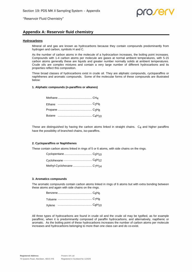
Section 19: PDS MK II Sampling System – Appendix
“Reservoir Fluid Chemistry”
Registered Address: 70 Queens Road, Aberdeen, AB15 4YE
Proserv UK Ltd Registered in Scotland No 122029
Appendix A: Reservoir fluid chemistry
Hydrocarbons
Mineral oil and gas are known as hydrocarbons because they contain compounds predominantly from hydrogen and carbon, symbols H and C.
As the number of carbon atoms in the molecule of a hydrocarbon increases, the boiling point increases. Compounds with 1-4 carbon atoms per molecule are gases at normal ambient temperatures, with 5-15 carbon atoms generally these are liquids and greater number normally solids at ambient temperatures. Crude oils are complex mixtures and contain a very large number of different hydrocarbons and its properties reflect this composition.
Three broad classes of hydrocarbons exist in crude oil. They are aliphatic compounds, cycloparaffins or naphthenes and aromatic compounds. Some of the molecular forms of these compounds are illustrated below:
1. Aliphatic compounds (n-paraffins or alkanes)
Methane .......................................... CH4
Ethane .......................................... C2H6
Propane .......................................... C3H8
Butane .......................................... C4H10
These are distinguished by having the carbon atoms linked in straight chains. C4 and higher paraffins have the possibility of branched chains, iso-paraffins.
2. Cycloparaffins or Naphthenes
These contain carbon atoms linked in rings of 5 or 6 atoms, with side chains on the rings.
Cyclopentane .................................. C5H10
Cyclohexane ................................... C6H12
Methyl-Cyclohexane ....................... C7H14
3. Aromatics compounds
The aromatic compounds contain carbon atoms linked in rings of 6 atoms but with extra bonding between these atoms and again with side chains on the rings.
Benzene .......................................... C6H6
Toluene .......................................... C7H8
Xylene .......................................... C8H10
All three types of hydrocarbons are found in crude oil and the crude oil may be typified, as for example paraffinic, when it is predominantly composed of paraffin hydrocarbons, and alternatively, napthenic or aromatic. As the boiling point of these hydrocarbons increases the number of carbon atoms per molecule increases and hydrocarbons belonging to more than one class can and do co-exist.

Section 19: PDS MK II Sampling System – Appendix
“Reservoir Fluid Chemistry”
Registered Address: 70 Queens Road, Aberdeen, AB15 4YE
Proserv UK Ltd Registered in Scotland No 122029
Other types of hydrocarbons such as olefins or alkenes do exist and are of great importance in petroleum processing and petrochemical manufacture. They are not however found in any significant amounts in crude oil.
Sulphur compounds
Sulphur is found in many crude oils normally in the range of 0.1 to 5.0% weight. The element is very rarely present in the free-state but is usually combined with hydrogen as hydrogen sulphide H2S and/or with carbon and hydrogen, such as;
C2H5SH .......................................... Ethyl Mercaptan
C2H5S-C5H5 .................................. Diethyl Sulphide
C4H4S .......................................... Thiophen
These compounds are normally only present when there is a relatively high concentration of H2S (>5000 ppmv). Apart from the mercaptans the other sulphur compound formulae can be derived from a corresponding hydrocarbon by replacing CH or CH2 by S. In most crude oils the percentage of sulphur in the oil increases with the boiling point, i.e. the naphtha fractions may have up to 0.1% sulphur, the gas fractions up to 1% and the residues up to 5% sulphur.
Other substances
Water and inorganic salts are often present in a reservoir but are relatively easy to remove during processing by simple separation systems and are not chemically speaking part of the crude oil.
Other elements present in crude oil in much smaller amounts than sulphur (ppm level) but of importance to the refining and/or use of the crude are oxygen, nitrogen, nickel and vanadium.
Oxygen is combined in what are known as naphthenic acids normally detected by determining the acid value of the crude oil and of products derived from it. Naphthenic acids are of importance for potential corrosion of handling and distillation equipment. If present in sufficient amounts they can be recovered for chemical use.
Nitrogen if present will be found in the higher boiling fraction of crude vacuum gas oils and residues and can be of importance to use of these products.
Nickel and Vanadium if present will be found only in the residual fractions of crude oil. If present in more than a few ppm they can be of importance to the use of these fractions.
PVT properties
Changes of state
In order to study the properties of gases and hydrocarbon liquids we need to understand the relationship between them. This is best understood by considering molecular behaviour and its effect on three physical properties, please see below:
Pressure (P) - which is a function of molecular attraction and repulsion
Volume (V) - which is a function of the number of molecules present
Temperature (T) - which is a function of the kinetic energy of the molecules
When a material appears to be at rest it is actually in dynamic equilibrium between the attractive and repulsive forces.

Section 19: PDS MK II Sampling System – Appendix
“Reservoir Fluid Chemistry”
Registered Address: 70 Queens Road, Aberdeen, AB15 4YE
Proserv UK Ltd Registered in Scotland No 122029
If one of the physical properties is changed (P.V. or T.) then equilibrium must be established. For example, if heat is added to a liquid system the temperature rises, because of the increase in kinetic energy of the system and:
EITHER
Pressure increases in a closed system as a function of an increase in the number of impacts of the molecules on the surface of containment.
OR
In an open system the volume expands to accommodate the more excited molecules at the same pressure.
In the extreme case when enough heat is added the forces become unbalanced (boiling liquid) and the material changes state into the gas phase.
Phase behaviour is best understood by considering phase diagrams.
Pure Substances
First, consider the simple phase diagram of a pure substance.
Figure 106: Phase diagram for a pure substance
The phase diagram is a plot of Pressure against Temperature. For the purposes of hydrocarbon chemistry we can ignore the 'Solid' part of the phase diagram and concentrate on the vapour pressure line TC with particular reference to C the critical point. The temperature and pressure at this point are defined as:

Section 19: PDS MK II Sampling System – Appendix
“Reservoir Fluid Chemistry”
Registered Address: 70 Queens Road, Aberdeen, AB15 4YE
Proserv UK Ltd Registered in Scotland No 122029
Critical Temperature (Tc): The temperature above which a gas cannot be liquefied regardless of the pressure applied
Critical Pressure (Pc): The pressure above which liquid and gas cannot co-exist regardless of temperature.
Two Component Systems
Now consider a two component system.
Figure 107: Phase diagram for a two component system
There is developed a phase envelope. The line AC is the Bubble Point Locus and BC is the Dew Point Locus.
Observe that the definition of critical point C applied to the pure component does not apply. Clearly liquid and gas can co-exist at temperatures and pressures above the critical point. The critical point is merely the point at which the Bubble Point locus and the Dew Point locus meet.
This type of behaviour becomes more exaggerated as the complexity of a hydrocarbon mixture increases as is shown in the next diagram.
It now becomes necessary to re-define the pressure and temperature above which gas and liquid cannot co-exist.
The cricondenbar is the pressure above which liquid cannot be formed and the cricondentherm is the temperature above which liquid cannot exist.

Section 19: PDS MK II Sampling System – Appendix
“Reservoir Fluid Chemistry”
Registered Address: 70 Queens Road, Aberdeen, AB15 4YE
Proserv UK Ltd Registered in Scotland No 122029
Figure 108: Phase diagram illustrating the Cricondenbar and Cricondemtherm
Multi-component Mixtures (Reservoir Fluids)
Now consider ‘real’ complex hydrocarbon fluids, below are presented typical phase diagrams for reservoir fluids under the normal classifications accepted in petroleum engineering.
Figure 109: Phase diagram for a Low Shrinkage Black Oil

Section 19: PDS MK II Sampling System – Appendix
“Reservoir Fluid Chemistry”
Registered Address: 70 Queens Road, Aberdeen, AB15 4YE
Proserv UK Ltd Registered in Scotland No 122029
Figure 110: Phase diagram for a High Shrinkage Oil
Figure 111: Phase diagram for a Wet Gas

Section 19: PDS MK II Sampling System – Appendix
“Reservoir Fluid Chemistry”
Registered Address: 70 Queens Road, Aberdeen, AB15 4YE
Proserv UK Ltd Registered in Scotland No 122029
Figure 112: Phase diagram for a Gas Condensate
Figure 113: Phase diagram for a Dry Gas

Section 19: PDS MK II Sampling System – Appendix
“Reservoir Fluid Chemistry”
Registered Address: 70 Queens Road, Aberdeen, AB15 4YE
Proserv UK Ltd Registered in Scotland No 122029
As previously stated, phase diagrams are plots of pressure against temperature, whereas in petroleum engineering it is more usual to consider pressure vs. volume (PV) at a fixed or perhaps one or two fixed temperatures.
In this case it is interesting to consider the isotherm marked 1-2-3 on the phase diagrams which represents reservoir temperature.
With reservoir oils a drop in pressure from 1-2 brings reaches the Bubble Point (the point at which the first bubble of gas from the lightest component in the mixture appears). With progress from 2-3 the gas becomes progressively richer in heavier components, as the liquid becomes progressively depleted of light ends.
With condensate reservoir gases a drop in pressure from 1-2 brings reaches the Dew Point (the point at which the first drop of liquid appears). In this case it is termed retrograde condensation, which is that the heaviest components drop out first and the gas stream becomes progressively lighter as pressure drops.
Now consider what happens in practice when the reservoir fluid is produced to the surface, giving rise to both a drop in pressure and temperature.
This is demonstrated by reference to the dotted line on the phase diagrams marked 2-Sep. The point marked 'Sep' denotes the Separator Pressure and Temperature.
With oils and condensate gases the system remains within the phase envelope where liquid and gas can co-exist. The actual point within the phase envelope defines the relative compositions of the oil and gas according to physico-chemical parameters which are explained later.
What is interesting to observe is that the Wet Gas produces no liquid (in the reservoir) along the isotherm 1-2 but if the drop in pressure is accompanied by a drop in temperature, as happens during production, then liquid is produced at separator pressure and temperature. By definition a Dry Gas produces no liquid even at separator conditions, and any heavy components present have to be chilled out from the gas stream to bring the temperature within the phase envelope.
When a reservoir should be sampled
The aim of PVT Sampling is to obtain a small sample of fluid under pressure, which is identical to the reservoir fluid under initial conditions. To achieve this several factors must be taken into account and decisions made:
• Decide upon the condition of the well to be sampled.
• Decide which sampling technique will give the best chance of obtaining a representative fluid sample.
A field discovery well is usually subjected to relatively large drawdown pressures and considerable depletion in the production testing necessary to determine its extent. The second and third wells drilled will still encounter essentially virgin reservoir pressure and the problems associated with conditioning, sampling and analysis will be minimised.
Depletion of a reservoir below the bubble-point pressure, leads to extreme difficulty in obtaining a reliable sample. As the results from the analysis of reservoir fluids are generally used in material balance calculations it is desirable that the analysis is performed on original fluid samples. Extra pollution of data from a current bottom hole pressure to a higher bubble-point pressure is always hazardous and should only be attempted in extreme cases.

Section 19: PDS MK II Sampling System – Appendix
“Reservoir Fluid Chemistry”
Registered Address: 70 Queens Road, Aberdeen, AB15 4YE
Proserv UK Ltd Registered in Scotland No 122029
Considerations for Well Sampling For the results of the fluid analysis to be of maximum value in the reservoir study, the sample must be representative of the phase that saturated the reservoir rock initially. In an oil reservoir it will be the gas phase.
The well to be sampled should meet as many of the following conditions as possible:
• The well should be centrally located in the field.
• It should have as high a productivity index as possible.
• The well should be completed in the section of the reservoir to be studied. In most cases this will be the oil zone. Care should be taken to eliminate any possibility of gas coning.
• The well should be free from water production.
• The flow in the reservoir should be single phase.
• If bottom hole sampling is required, then the sample should be taken at or as close to the perforations as possible.
Data Required Prior to Sampling Before sampling is attempted it is important to obtain preliminary details of the reservoir and well characteristics for example:
• The type of fluid expected to be encountered. Oil, gas/condensate, or water
• Whether it is saturated or under saturated.
• Whether the formation has high or low permeability.
In exploration wells Standing's correlations can be used to estimate the bubble-point pressure at formation temperature. To use these correlations the following data is required:
• Initial and present static reservoir pressure.
• Reservoir temperature.
• Oil and gas gravities.
• Stabilised gas-oil ratios at one or more flow rates.
Oil reservoirs
Under saturated reservoirs
These reservoirs are characterised by a constant G.O.R. equal to the maximum gas solubility in the oil. Bottom hole sampling and surface sampling can be carried out with the well flowing at any stabilised flow rate for which flowing reservoir pressure exceeds saturation pressure at reservoir conditions.
Saturated Reservoirs
In these reservoirs the G.O.R. is only equal to the maximum gas stability in oil during a very short initial flow period. The G.O.R. then increases as the well is produced. Saturation pressure is equal to or near the initial static reservoir pressure, and if an initial gas cap is present will always equal the initial pressure.
Bottom hole sampling can be carried out if the following procedures are adopted.
Section 19: PDS MK II Sampling System – Appendix
“Reservoir Fluid Chemistry”
Registered Address: 70 Queens Road, Aberdeen, AB15 4YE
Proserv UK Ltd Registered in Scotland No 122029
The flow rate should be progressively reduced and then the well finally shut-in. During this process the flowing bottom hole pressure will increase and the free gas produced into the well bore, or remain stationary within the oil phase until the well is shut in. Reservoir saturation pressure should be near to the initial static reservoir pressure.
At this point the well should be opened on the smallest possible choke (e.g. 1/16") and flowed for 10 to 15 minutes before the sampler closes. During this short flow period draw down should be minimised and any liberated gas should be too small to affect the validity of the samples.
The flow rate would be progressively reduced over a long period (depending on the permeability of the reservoir) and finally shut in. During this period the flowing bottom hole pressure will increase until it approaches the initial static bottom hole pressure. The movable free gas will be produced into the well bore and the stationary free gas will remain in the pore space of the reservoir. This remaining free gas reduces the effective permeability of the reservoir rock to single-phase reservoir fluid, and increases the pressure drawdown.
Surface sampling
Surface Sampling can only be carried out if at the minimum stabilised flow rate the G.O.R. is very close to the initial G.O.R.
Gas/Condensate reservoirs
Since for these reservoirs it is difficult to determine from the well test data the exact nature of the reservoir, sampling should always be carried out assuming the worse case, i.e. a saturated reservoir with a dew point equal to the initial static pressure.
Surface sampling should always be carried out for gas/condensate reservoirs, PDS. bottom hole sampling is unsuitable for the following reasons:
1. PVT laboratory analysis normally requires a larger sample volume than the 600 ml available from bottom hole samplers.
2. If a sample were taken, the effect of bringing the sampler to surface conditions would cause liquid to condense in the Sample Chamber. This liquid would in most cases be only a small amount and would remain behind, wetting the walls of the Chamber, during a normal transfer at atmospheric temperature. The normal practice of heating the Sample Chamber at surface before transfer is no guarantee that single-phase equilibrium conditions can be achieved in the field.
Bottom hole sampling can be considered if the reservoir is known to be under-saturated and using a Single-Phase Sampler.
In addition to the normal criteria for surface sampling in dealing with gas/condensate reservoirs, a further parameter has to be met. The liquid condensed in the tubing, between the bottom of the well and the surface must be produced into the separator. This requires a production rate that is sufficient to lift any condensed liquids to surface. The general rule is; gas/condensate reservoirs are produced at a maximum stable production rate. Of course, this does not apply to every case and exceptions arise when formation porosity is such that there is liquid condensed in the formation around the well bore during the clean up phase of the well test. In the most extreme case it could take months for a well under flowing conditions to produce representative equilibrium reservoir fluid at surface.

Section 19: PDS MK II Sampling System – Appendix
“Reservoir Fluid Chemistry”
Registered Address: 70 Queens Road, Aberdeen, AB15 4YE
Proserv UK Ltd Registered in Scotland No 122029
Volatile oil reservoir
A volatile oil is one with very high gas solubility in relation to its bubble point pressure and because of its high G.O.R. and low relative density can be confused in the field with a gas/condensate reservoir. Because of these unusual characteristics, Standing's correlations cannot be used to determine bubble point pressure, therefore, these reservoirs should be sampled as gas/condensates. If PVT analysis shows that it is an oil reservoir and the bubble point is established, bottom hole sampling can be employed on subsequent wells.
Well conditioning
The well should be flowed until a stabilised rate is achieved such that the G.O.R. is equal to the initial G.O.R. Stability should be achieved for a minimum of 4 hours for bottom hole sampling and 12 hours for surface sampling with a flowing bottom hole pressure greater than the bubble point pressure. During this period the oil and gas flow rates, well-head pressure, and flowing bottom hole pressure should all be constant. The latter gives the best indication of stability but can only be used if electronic surface read-out gauges are available.

SAMPLE CYLINDER
TYPE 5 (10K) 850669‐700
USER SPARE PARTS LIST
File:..\ PDS SPS Manual Source (rev6453) 18‐05‐2012 CB REV. DATE: 11.12.09 Last printout: 20.05.12 13:18 Page 1 of 2
PNS 0261 rev 1 issue 1 Appx. A – B 14/11/2002 All information is subject to change without further notice.
Registered Address: 70 Queens Road, Aberdeen, AB15 4YE
Proserv UK Ltd Registered in Scotland No 122029
TYPE 5 10K CYLINDER PARTS INVENTORY
Item Qty. Part No. Description
1 1 850669-1 Cylinder Body
2 1 850669-9 Sample End Cap
3 1 850669-3 Non-Sample End Cap
4 1 850669-5 Floating Piston
5 1 850409-7 Scraper Ring
6 1 1 1/2 Dia 316 SS Bal Agitation Ball
7 2 CAG078-1464 Protection Cage
8 2 BTV4B4P2TGE1526 Valve (Cylinder)
9 2 1/4 NPT SS Socket Head Grub Screw
10 2 77mm x 2.65mm External Circlip
11 2 68mm X 2.65mm Internal Circlip Zinc/Lipped
12 4 50-834GFS Back Up Ring
13 4 50-834V90 O Ring
14 1 122329007310450 Tee Seal Assembly
15 1 850409-5 Vacuum Port Nipple
16 1 50-010V90 O Ring
17 1 850409-6 Vacuum Port Nipple Plug
18 1 50-006V90 O Ring
1 4 2 8
11 6 5
3 9 7
10 12
1314
15 16 17 18

SAMPLE CYLINDER
TYPE 5 (10K) 850669‐700
USER SPARE PARTS LIST
File:..\ PDS SPS Manual Source (rev6453) 18‐05‐2012 CB REV. DATE: 11.12.09 Last printout: 20.05.12 13:18 Page 2 of 2
PNS 0261 rev 1 issue 1 Appx. A – B 14/11/2002 All information is subject to change without further notice.
Registered Address: 70 Queens Road, Aberdeen, AB15 4YE
Proserv UK Ltd Registered in Scotland No 122029
TYPE 5 10K CYLINDER LIST OF WORKSHOP TOOLS AND ACCESSORIES
Item Qty. Part No. Description
19 1 212450-101 Hand Pump w/Swivel Adaptor
20 1 850337 Piston Removal Tool Assembly
21
22
1
1
850340/CCLX/CGLX
8000-J.31
Autoclave Vacuum Nipple Assembly
Circlip Pliers (Internal)
23 1 117B Pin Spanner
24 1 8000-A3 Circlip Pliers (External Straight) Geodore
25 1 850339/CCLX/CGLX Prime Hand Pump Adapter Assy
26 1 850669-WT&A-070014 Type 5 10 K Tool Box
27 1 1/4 AF Allen Key
TYPE 5 10K CYLINDER REDRESS KIT
Item Qty. Part No. Description
28 1 850409-7 Scraper Ring
29 4 50-834V90 O Ring
30 1 122329007310450 Tee Seal Assembly
31 4 50-834GFS Back Up Ring
32 2 68mm X 2.65mm Internal Circlip Zinc/Lipped
33 2 77mm x 2.65mm External Circlip
34 1 50-010V90 O Ring
35 1 50-006V90 O Ring

SAMPLE CYLINDER
TYPE 5 (15K) 850870-700 USER SPARE PARTS LIST
PNS 0261 Rev 1 Issue 1 Appx A-B 11/12/2009
PDS SPS Manual Source (rev6453) 18‐05‐2012 CB Last printout: 20.05.12 13:18 ISO 9001 CERTIFIED
All information is subject to change without further notice. Registered Address: 70 Queens Road, Aberdeen, AB15 4YE
Proserv UK Ltd Registered in Scotland No 122029
Registered in Scotland No: 122029
TYPE 5 (15K) CYLINDER PARTS INVENTORY
Item Qty. Part No. Description 1 1 850870-1 Cylinder Body 2 1 850870-2 Sample End Cap 3 1 850870-3 Non Sample End Cap 4 1 850870-4 Floating Piston Single Ball 5 2 850409-7 Scraper Ring 6 1 1 1/2 Dia 316 SS Bal Agitation Ball 7 2 CAG078-1464 Protection Cage 8 8
2 2
US6130-ESR1514 101A-6751 A. E.
20K Valve Stem Assembly “V” Stem Assembly
8 2 101A-6754 A. E. Packing Gland 8 8
2 2
P-1240 P-0129
Locking Device Lock Screw
8 4 P-1691 A. E. Valve Packing 8 2 1120-7638 A. E. Bottom Washer 8 2 1090-7638 A. E. Packing Washer 8 2 P-0129 Locking Device Screw (20K) 8 2 102B-7568 Valve Handle
82 144
11
7121
5
315
6 9 10
16 1718 19
20 21
13
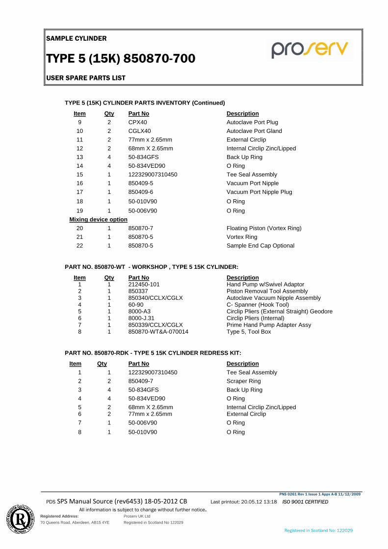
SAMPLE CYLINDER
TYPE 5 (15K) 850870-700 USER SPARE PARTS LIST
PNS 0261 Rev 1 Issue 1 Appx A-B 11/12/2009
PDS SPS Manual Source (rev6453) 18‐05‐2012 CB Last printout: 20.05.12 13:18 ISO 9001 CERTIFIED
All information is subject to change without further notice. Registered Address: 70 Queens Road, Aberdeen, AB15 4YE
Proserv UK Ltd Registered in Scotland No 122029
Registered in Scotland No: 122029
TYPE 5 (15K) CYLINDER PARTS INVENTORY (Continued)
Item Qty Part No Description9 2 CPX40 Autoclave Port Plug
10 2 CGLX40 Autoclave Port Gland 11 2 77mm x 2.65mm External Circlip 12 2 68mm X 2.65mm Internal Circlip Zinc/Lipped 13 4 50-834GFS Back Up Ring 14 4 50-834VED90 O Ring 15 1 122329007310450 Tee Seal Assembly 16 1 850409-5 Vacuum Port Nipple 17 1 850409-6 Vacuum Port Nipple Plug 18 1 50-010V90 O Ring 19 1 50-006V90 O Ring
Mixing device option 20 1 850870-7 Floating Piston (Vortex Ring) 21 22
1 1
850870-5 850870-5
Vortex Ring Sample End Cap Optional
PART NO. 850870-WT - WORKSHOP , TYPE 5 15K CYLINDER:
Item Qty Part No Description1 1 212450-101 Hand Pump w/Swivel Adaptor 2 1 850337 Piston Removal Tool Assembly 3 1 850340/CCLX/CGLX Autoclave Vacuum Nipple Assembly 4 1 60-90 C- Spanner (Hook Tool) 5 1 8000-A3 Circlip Pliers (External Straight) Geodore 6 1 8000-J.31 Circlip Pliers (Internal) 7 1 850339/CCLX/CGLX Prime Hand Pump Adapter Assy 8 1 850870-WT&A-070014 Type 5, Tool Box
PART NO. 850870-RDK - TYPE 5 15K CYLINDER REDRESS KIT:
Item Qty Part No Description1 1 122329007310450 Tee Seal Assembly 2 2 850409-7 Scraper Ring 3 4 50-834GFS Back Up Ring 4 4 50-834VED90 O Ring 5 2 68mm X 2.65mm Internal Circlip Zinc/Lipped 6 2 77mm x 2.65mm External Circlip 7 1 50-006V90 O Ring 8 1 50-010V90 O Ring

SAMPLE CYLINDER
TYPE 6 (10K) 850409-700 USER SPARE PARTS LIST
PNS 0261 Rev 1 Issue 1 Appx A-B 11/12/2009
PDS SPS Manual Source (rev6453) 18‐05‐2012 CB Last printout: 20.05.12 13:18 ISO 9001 CERTIFIED
All information is subject to change without further notice.
Registered Address: 70 Queens Road, Aberdeen, AB15 4YE
Proserv UK Ltd Registered in Scotland No 122029
Registered in Scotland No: 122029
TYPE 6 (10K) CYLINDER PARTS INVENTORY
Item Qty. Part No. Description 1 1 850409-1 Nitrogen Reservoir Body 2 1 850409-2 Nitrogen Reservoir Plug 3 1 850409-3 Sample Cylinder Body 4 1 850409-3 Sample Cylinder Body 5 1 850409-5 Vacuum Port Nipple 6 1 850409-6 Vacuum Port Nipple Plug 7 1 850870-4 Floating Piston (Multi Ball) 8 1 850870-5 Floating Piston (Vortex Ring) 9 1 850870-6 Vortex Ring – Not Shown
10 2 FVX2A22NT61110HT-SG Valve (Anti Tamper RA Forged Body)1/4 NPT 11 2 611-10HT-AT-316-SG Anti Tamper Bonnet Assembly 12 1 CGLX 40 Autoclave Port Gland 13 1 CPX 40 Autoclave Port Plug 14 2 1/4 NPT SS Socket Head Grub Screw 15 1 01-4153-01 Anti-Tamper Key – Not Shown 16 50 ¼” Diameter Mixing Balls
1
5
6
3 7 10 12 11 13
14
14 162 10
19
20
21
23
22 24
25
26

SAMPLE CYLINDER
TYPE 6 (10K) 850409-700 USER SPARE PARTS LIST
PNS 0261 Rev 1 Issue 1 Appx A-B 11/12/2009
PDS SPS Manual Source (rev6453) 18‐05‐2012 CB Last printout: 20.05.12 13:18 ISO 9001 CERTIFIED
All information is subject to change without further notice.
Registered Address: 70 Queens Road, Aberdeen, AB15 4YE
Proserv UK Ltd Registered in Scotland No 122029
Registered in Scotland No: 122029
TYPE 6 (10K) CYLINDER PARTS INVENTORY (Continued)
Item Qty Part No Description17 1 78074-20A 3-3/4" Protection Cover (Sample End, Not Shown) 18 1 850409-9 4-1/8" Protection Cover (N2 End – Not Shown) 19 1 50-006V90 O Ring 20 1 50-010V90 O Ring 21 1 122329007310450 Tee Seal Assembly 22 1 50-214VED90 O Ring 23 2 50-214GFS 25% Glass Filled PTFE Solid Back Up Ring 24 2 50-834VED90 O Ring 25 2 50-834GFS Back Up Ring 26 2 850409-7 Scraper Ring
PART NO. 850409-WT – TYPE 6 10K WORKSHOP TOOLS
Item Qty Part No Description27 1 850337 Piston Removal Tool Assembly
28 1 212450-101 Hand Pump w/Swivel Adaptor
29 1 850339/CCLX/CGLX Prime Hand Pump Adaptor Assy
30 1 3/32 AF Allen Key
31 1 850340/CCLX/CGLX Autoclave Vacuum Nipple Assembly
32 1 1/4 AF Allen Key
33 1 117B Pin Spanner
34 35
1 1
3151 850409-WT&A-94-22315
C-Spanner Type 6 10K Cylinder Work/Tools Box
PART NO. 850409-RDK – TYPE 6 10K CYLINDER REDRESS KIT:
Item Qty Part No Description36 2 850409-7 Scraper Ring 37 1 122329007310450 Tee Seal Assembly 38 2 50-834VED90 O Ring 39 1 50-010V90 O Ring 40 1 50-006V90 O Ring 41 1 50-214VED90 O Ring 42 2 50-834GFS Back Up Ring 43 2 50-214GFS 25% Glass Filled PTFE Solid Back Up Ring

SAMPLE CYLINDER
TYPE 6 (10K) 850409-700 USER SPARE PARTS LIST
Registered Address: 70 Queens Road, Aberdeen, AB15 4YE
Proserv UK Ltd Registered in Scotland No 122029
1 24 5
98
11
12 10
3
6
7
8 9 11
13
8
1412
9
TYPE 6 (15K) CYLINDER PARTS INVENTORY
Item Qty. Part No. Description 1 1 850852-1 Nitrogen Reservoir Body 2 1 850852-2 Cylinder Body 3 1 850409-2 Nitrogen Reservoir Plug 4 1 850870-5 Floating Piston (Vortex Ring) 5 1 850870-6 Vortex Ring 6 1 850409-5 Vacuum Port Nipple 7 1 850409-6 Vacuum Port Nipple Plug 8 3 CGLX 40 Autoclave Port Gland 9 3 CPX 40 Autoclave Port Plug
10 1 PLAA2528010A Lee Plug 11 2 US6131-ESR1514 30K Valve Stem Assembly 12 2 US6130-ESR1514 20K Valve Stem Assembly 13 4 850871 Valve Handle Adaptor 14 2 A.E. 30K L.D. Locking Device for 30K Valve Stem Assy 15 2 A.E. 20K L.D. Locking Device for 20K Valve Stem Assy 16 1 01-4153-01 Anti-Tamper Key (Cast) – Not Shown 17 1 78074-20A 3-3/4" Protection Cover 18 1 850409-9 4-1/8" Protection Cover 19 1 50-006V90 O Ring 20 1 50-010V90 O Ring 21 1 122329007310450 Tee Seal Assembly

SAMPLE CYLINDER
TYPE 6 (10K) 850409-700 USER SPARE PARTS LIST
Registered Address: 70 Queens Road, Aberdeen, AB15 4YE
Proserv UK Ltd Registered in Scotland No 122029
TYPE 6 (15K) CYLINDER PARTS INVENTORY (Continued) 22 1 50-214VED90 O Ring 23 2 50-214GFS 25% Glass Filled PTFE Solid Back Up Ring24 2 50-834VED90 O Ring 25 2 50-834GFS Back Up Ring 26 2 850409-7 Scraper Ring
PART NO. 850852-WT – TYPE 6 15K WORKSHOP TOOLS:
Item Qty Part No Description27 1 850337 Piston Removal Tool Assembly
28 1 212450-101 Hand Pump w/Swivel Adaptor
29 1 850339/CCLX/CGLX Prime Hand Pump Adaptor Assembly
30 1 3/32 AF Allen Key
31 1 1/8 AF Allen Key
32 1 1/4 AF Allen Key
33 1 850340/CCLX/CGLX Autoclave Vacuum Nipple Assembly
34 1 117B Pin Spanner
35 36 37 38
1 1 1 1
3151 86600.0.5066 86600.0.5050 850852-WT&A-94-22315
C-Spanner Spanner 1/2" AF Ring & Open end Special Ring Spanner Type 5 10 K Tool Box
PART NO. 850852-RDK – TYPE 6 15K CYLINDER REDRESS KIT:
Item Qty Part No Description39 2 850409-7 Scraper Ring 40 1 122329007310450 Tee Seal Assembly 41 2 50-834VED90 O Ring 42 2 50-834GFS Back Up Ring 43 1 50-214VED90 O Ring 44 2 50-214GFS 25% Glass Filled PTFE Solid Back Up
Ring 45 1 50-010V90 O Ring 46 1 50-006V90 O Ring


![Dangc Pds 71 Pds Ngc Model700[1]](https://img.dokumen.tips/doc/110x75/577cc1111a28aba71192272d/dangc-pds-71-pds-ngc-model7001.jpg)