Embed Size (px)
Citation preview

PDS-360 ULTRASONIC
OPEN-CHANNEL FLOWMETER
INSTRUCTION MANUAL
Ship To:
CONTROL ELECTRONICS, INC.148 Brandamore Rd.
Brandamore, PA 19316
Mail To:
CONTROL ELECTRONICS,INC.P.O. Box 330
Brandamore, PA 19316
Tel: (610) 942-3190 Fax: (610) 942-3672
Via UPS
http://www.controlelectronics.com e-mail: [email protected]

INDEX
SPECIFICATIONS ....................................................... III.REPAIR / RETURN POLICY ..................................... IV.PRODUCT PERFORMANCE STATEMENT ....... V.WARRANTY .................................................................... VI. ... Please read first before installing flow meter.
INTRODUCTION ............................................................ 1.INSTALLATION .............................................................. 2.
1. Enclosure Location ............................................. 2.2. Sensor Location .................................................. 3.
a] Parshall Flume b] Palmer/Bowlus Flumec] V-Notch Weird] Rectangular Weirse] Stilling Wells
3. Enclosure Mounting ........................................... 5.4. Sensor Mounting ................................................ 6.5. Electrical Connections ....................................... 7.
Sensor Cable ............................................. 7.4-20mA. Output .......................................... 8. Sampler/Counter Relay Output .............. 8.
Setpoint Relay Outputs ............................. 8.0-10 VDC Output ....................................... 9.120VAC Input ............................................. 9.AC Output ................................................... 9.Heater ......................................................... 9.DC Volt Outputs ........................................ 9.Battery Operation ..................................... 9.Shut OFF .................................................... 9.
ADJUSTMENTS AND CONTROLS ...................... 10.1. Transmitter / Receiver Card ............................. 10.
GAIN adjust ................................................ 10.J1 / J2 Threshold Jumpers ...................... 10.Xmit / L2 Tuning Coil ................................ 10.
2. Main Circuit Board ............................................. 11.4-20mA. adjustments ............................... 11.0-10VDC adjustment ................................ 11.DAMP Adjustment ..................................... 11.ON/OFF switch ........................................... 11.120/220VAC Select .................................. 11.
FRONT PANEL ...............................................................11.Pass Code .................................................. 11.
LCD DISPLAY ............................................................... 12.Indicator Type ............................................ 12.GPM, MGD ................................................. 12.Totalizer ...................................................... 12. I .

INDEX ( CONT’D)FLOW % ...................................................... 13.Temperature Reading .............................. 13.DEPTH ........................................................ 12.LF (Low Flow) ............................................ 12.* Asterisk ..................................................... 13.
CLAIBRATION .............................................................. 14.CHANGING CALIBRATION REFERENCE ........ 14.SETTING THE ANALOG OUTPUTS ................... 15.SETTING SAMPLER / COUNT OUTPUTS ...... 15.
SETTING ALARM CONTROLS .............................. 15. 3 Volt Battery ................................................................ 15.
Programming The Flowmeter
USING THE PROGRAM FLOWCHART .............. 16.Operating Instructions ............................................. 16.Resetting The Flowmeter ....................................... 16.If Flowmeter Should Lock-up ................................ 16.Power Up Flowmeter .............................................. 17.RUN MODES ........................................................... 17.Set PRIMARY DEVICE ........................................... 17.Pass Code ................................................................ 17.Setting FLOW PARAMETERS ............................... 18.SETPOINTS .............................................................. 19.Sampler / External Counter Pulse ........................ 19.Set CALIBRATION REFERENCE .......................... 20.Set TIME/DATE ........................................................ 20.Reset TOTALIZER / DATA LOG ............................. 20.Set Communications .............................................. 20.Viewing the DATA LOG .......................................... 21.Print / Download DATA LOG ................................. 22.
USING RS-232 COMMUNICATION PORT ...... 24.Initiate DOWNLOAD from the flowmeter ............. 24.Initiate DOWNLOAD from a PC or Laptop .......... 25.RS-232 Wiring .......................................................... 26.
ILLUSTRATIONSFlume - Weir Types ............................................... 3 & 4.Front Panel Display Samples .......................... 12 & 13.FIGURE 1. Enclosure Mounting / Dimensions ..... 5.FIGURE 2. Sensor Mounting ................................... 6.FIGURE 3. PDS-360 Wiring Diagram .................... 8.FIGURE 4. Ultrasonic Xmit / Receive Card .......... 10.FIGURE 5. PVC Sensor Mounting Bracket .......... 23.RS-232 Wiring Diagram .......................................... 26.
II .
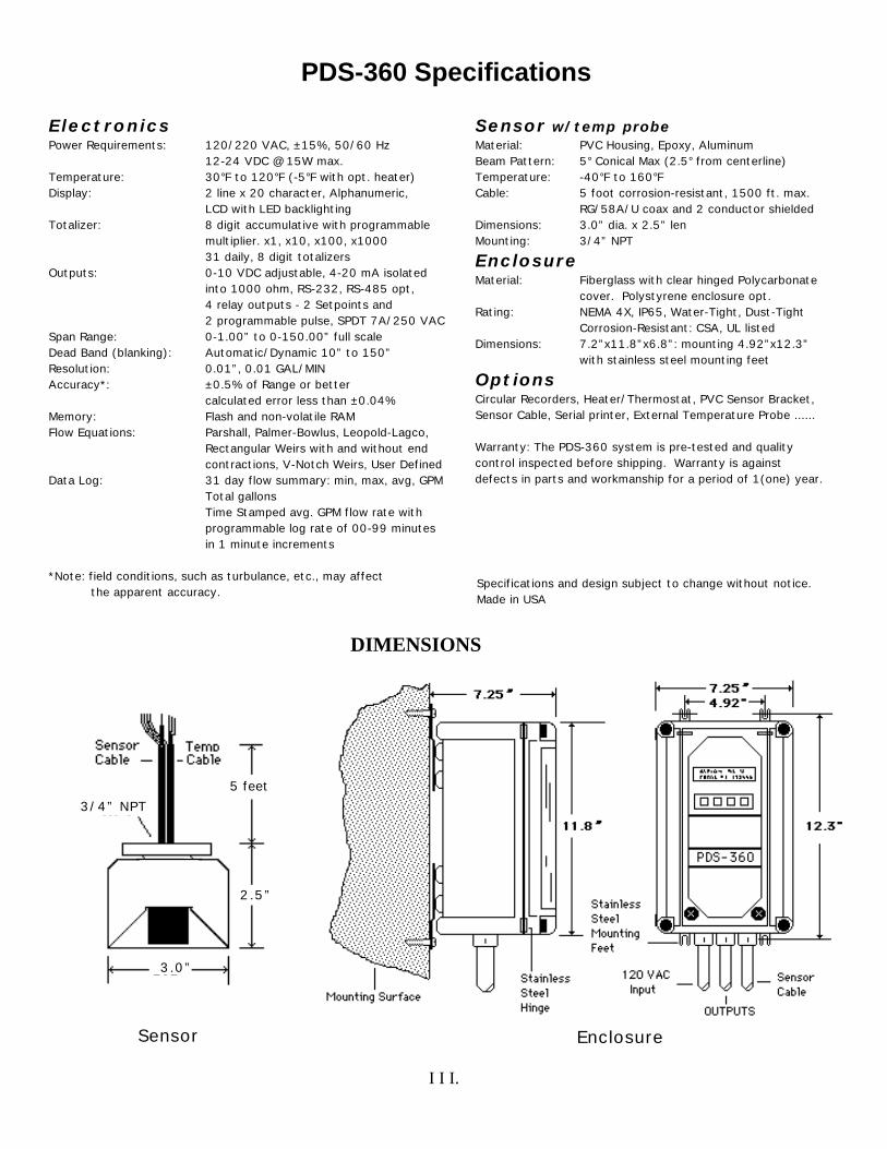
Sensor w/temp probeMaterial: PVC Housing, Epoxy, AluminumBeam Pattern: 5° Conical Max (2.5° from centerline)Temperature: -40°F to 160°FCable: 5 foot corrosion-resistant, 1500 ft. max.
RG/58A/U coax and 2 conductor shieldedDimensions: 3.0” dia. x 2.5” len Mounting: 3/4” NPT
EnclosureMaterial: Fiberglass with clear hinged Polycarbonate
cover. Polystyrene enclosure opt.Rating: NEMA 4X, IP65, Water-Tight, Dust-Tight
Corrosion-Resistant: CSA, UL listedDimensions: 7.2”x11.8”x6.8”: mounting 4.92”x12.3”
with stainless steel mounting feet
OptionsCircular Recorders, Heater/Thermostat, PVC Sensor Bracket,Sensor Cable, Serial printer, External Temperature Probe ......
Warranty: The PDS-360 system is pre-tested and qualitycontrol inspected before shipping. Warranty is againstdefects in parts and workmanship for a period of 1(one) year.
ElectronicsPower Requirements: 120/220 VAC, ±15%, 50/60 Hz
12-24 VDC @ 15W max.Temperature: 30°F to 120°F (-5°F with opt. heater)Display: 2 line x 20 character, Alphanumeric,
LCD with LED backlightingTotalizer: 8 digit accumulative with programmable
multiplier. x1, x10, x100, x100031 daily, 8 digit totalizers
Outputs: 0-10 VDC adjustable, 4-20 mA isolatedinto 1000 ohm, RS-232, RS-485 opt,4 relay outputs - 2 Setpoints and 2 programmable pulse, SPDT 7A/250 VAC
Span Range: 0-1.00” to 0-150.00” full scaleDead Band (blanking): Automatic/Dynamic 10” to 150”Resolution: 0.01”, 0.01 GAL/MINAccuracy*: ±0.5% of Range or better
calculated error less than ±0.04%Memory: Flash and non-volatile RAMFlow Equations: Parshall, Palmer-Bowlus, Leopold-Lagco,
Rectangular Weirs with and without endcontractions, V-Notch Weirs, User Defined
Data Log: 31 day flow summary: min, max, avg, GPMTotal gallonsTime Stamped avg. GPM flow rate withprogrammable log rate of 00-99 minutesin 1 minute increments
*Note: field conditions, such as turbulance, etc., may affect the apparent accuracy.
PDS-360 Specifications
Specifications and design subject to change without notice.Made in USA
DIMENSIONS
Sensor
3/4” NPT
5 feet
2.5”
3.0”
I I I.
Enclosure

Repair Policy: All repairs are performed on our premises. Repairs must be sent to Control Electronics by UPS prepaid. Customer must enclose a description of problem, who to contact, phone number, return ship-to address and purchase order number to cover repairs. Delay of repair may occur if information is not provided. No ARM number is required.
Repair Cost: Most repairs are processed within 48 hours unless major repair is required. Minimal repair charge is $ 150.00 plus shipping. This covers most repairs. If repair exceeds $ 150.00, we will notify the customer before we proceed. Payment is COD or Credit Card only unless other arrangements are made.
MasterCard VisaAMERICAN EXPRESS
Warranty repairs are made at our discretion and returned UPS GROUND at our expense.
Return Policy: Control Electronics will accept ‘return of product’ for credit within 6 months (within 6 months) of shipping date if it is determined that the product is not performing to
specification as described in Product Performance statement in this manual (provided application is not the cause of problem). We do not accept returns for credit when the application is the source of the problem (i.e. poorly installed flumes, poor piping arrangements, interference from other equipment etc.) , product is misapplied or not used properly and/or if product is out of warranty (12 months from ship date).
(after 6 months) A 35% restocking charge will be applied if product is returned for credit after 6 months from ship date. ( 7 to 12th month from shipping date).
Control Electronics does not accept returns of options such as circular recorders and other products not manufactured by Control electronics, Inc.
Control Electronics will not accept returns of used Sensors, cables, or spare parts unless shown to be defective under warranty or not performing as specified.
Any credit issued will be at the discretion of Control Electronics, Inc. Warranty of product is limited only to the repair or replacement (with same model) of defective product.
Any product or part of product returned damaged will not be considered for any credit.
Customer must call for authorization before returning product for credit. Products returned for credit will not be considered without prior authorization.
A description of how it was determined that the product was not performing to specification must accompany the return of the product for our evaluation before Control Electronics will consider any credit. The name of who to contact along with phone number should also be included with the return.
Ship To Adress: All repairs or returns must be shipped prepaid via UPS or equal to:
Control Electronics, Inc., 148 Brandamore Rd., Brandamore, PA 19316
I V.

CONTROL ELECTRONICS, INC.
PDS-360 Product Performance
Control Electronics PDS-360 Flowmeter will perform as specified when tested under known, simulated conditions. All PDS-360’s are tested for full functionality and performance before shipping.
The accuracy of the product is determined by inputting a known, stable target distance into the system and monitoring its ability to process the return ECHO delay accurately and conversion of the calculated DEPTH indication to GPM and Total flow as related to the built-in equations. Specifications for the product are determined by this method.
The accuracy of the product is not determined by any other method. Other tests methods indicate the accuracy of the over-all application/installation, not just that of the product. Such tests are not acceptable as an indication of product(s) accuracy. However, other test methods can be used to determine if the calibration of the product should be changed in attempt to compensate for application/installation conditions. This should only be done if no other application/installation corrections can be initiated to correct the problem.
Some examples of application/installation problems are:
1] Flume/Weir not sized properly 2] Strong vapours from liquid or severe air density changes 3] too much turbulance or foaming on the liquid surface 4] Flow moving too fast through the flume/Weir 5] Flow approach to flume/weir incorrect6] Sensor not installed properly etc.
Some equipment such as variable speed drives, nearby radio transmitters (i.e.: radio dispatch or hand held transmitters) etc. located next to the product or even at times in adjacent rooms may possibly interfere with the products performance. The worst of these is the variable speed drive controllers. This type of equipment generates large amounts of electrical and RF (radio frequency) noise that can interfere with the products ability to interpret the return ECHO signal. Some adjustment to the product , relocation of the product or different electrical grounding attempts may minimize or eliminate the interference. Ultimately, it is up to the user to make the corrections necessary and require that the source that is causing the interference be corrected.
If you have any questions in regards to product performance, please contact Control Electronics at (610) 942-3190 or fax us with application conditions and questions at (610) 942-3672.You may also E-mail us at: [email protected] .
V .
CONTROL ELECTRONICS, INC.
PRODUCT WARRANTY
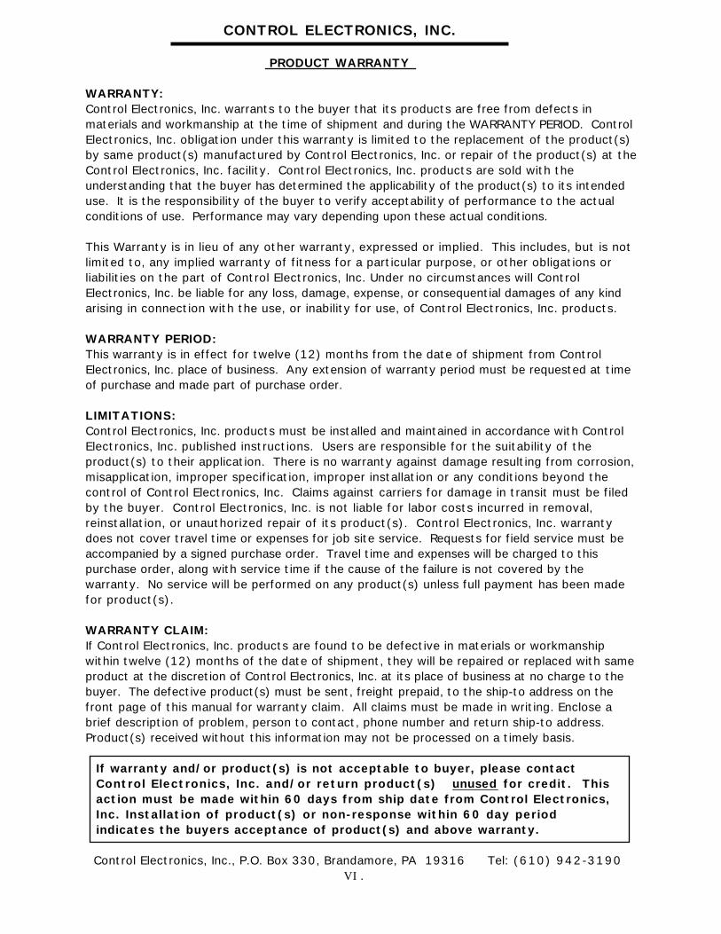
WARRANTY:Control Electronics, Inc. warrants to the buyer that its products are free from defects in materials and workmanship at the time of shipment and during the WARRANTY PERIOD. Control Electronics, Inc. obligation under this warranty is limited to the replacement of the product(s) by same product(s) manufactured by Control Electronics, Inc. or repair of the product(s) at the Control Electronics, Inc. facility. Control Electronics, Inc. products are sold with the understanding that the buyer has determined the applicability of the product(s) to its intended use. It is the responsibility of the buyer to verify acceptability of performance to the actual conditions of use. Performance may vary depending upon these actual conditions.
This Warranty is in lieu of any other warranty, expressed or implied. This includes, but is not limited to, any implied warranty of fitness for a particular purpose, or other obligations or liabilities on the part of Control Electronics, Inc. Under no circumstances will Control Electronics, Inc. be liable for any loss, damage, expense, or consequential damages of any kind arising in connection with the use, or inability for use, of Control Electronics, Inc. products.
WARRANTY PERIOD:This warranty is in effect for twelve (12) months from the date of shipment from Control Electronics, Inc. place of business. Any extension of warranty period must be requested at time of purchase and made part of purchase order.
LIMITATIONS:Control Electronics, Inc. products must be installed and maintained in accordance with Control Electronics, Inc. published instructions. Users are responsible for the suitability of the product(s) to their application. There is no warranty against damage resulting from corrosion, misapplication, improper specification, improper installation or any conditions beyond the control of Control Electronics, Inc. Claims against carriers for damage in transit must be filed by the buyer. Control Electronics, Inc. is not liable for labor costs incurred in removal, reinstallation, or unauthorized repair of its product(s). Control Electronics, Inc. warranty does not cover travel time or expenses for job site service. Requests for field service must be accompanied by a signed purchase order. Travel time and expenses will be charged to this purchase order, along with service time if the cause of the failure is not covered by the warranty. No service will be performed on any product(s) unless full payment has been made for product(s).
WARRANTY CLAIM:If Control Electronics, Inc. products are found to be defective in materials or workmanship within twelve (12) months of the date of shipment, they will be repaired or replaced with same product at the discretion of Control Electronics, Inc. at its place of business at no charge to the buyer. The defective product(s) must be sent, freight prepaid, to the ship-to address on the front page of this manual for warranty claim. All claims must be made in writing. Enclose a brief description of problem, person to contact, phone number and return ship-to address. Product(s) received without this information may not be processed on a timely basis.
If warranty and/or product(s) is not acceptable to buyer, please contact Control Electronics, Inc. and/or return product(s) unused for credit. This action must be made within 60 days from ship date from Control Electronics, Inc. Installation of product(s) or non-response within 60 day period indicates the buyers acceptance of product(s) and above warranty.
Control Electronics, Inc., P.O. Box 330, Brandamore, PA 19316 Tel: (610) 942-3190 VI .

INTRODUCTION
Control Electronics model PDS-360 Ultrasonic Open Channel flowmeter is a microprocessor controlled, non-contacting flowmetering system designed to accurately measure liquid flow through any standard primary flow device. The PDS-360 flowmeter has been designed with the user in mind, allowing for simple, intuitive set-up through a menu driven programming interface. Control Electronics has been designing and manufacturing Ultrasonic type flowmeters since 1980. The PDS-360 flowmeter represents the latest in microprocessor technology and ultrasonic echo-ranging techniques.
In theory, the PDS-360 system transmits high-frequency sound pulses from the sensor to the liquid flow surface and calculates the elapsed time of echo return. The elapsed time is directly related to distance and is used, along with a temperature measurement, to calculate an accurate Depth-of-Flow measurement. The system makes these measurements continuously and without contact to the flow. Depth-of-Flow is then converted to flow rate indication and totalization through the built-in mathematical conversion equations for the Primary Flow Device selected by the operator.
All PDS-360 circuits are protected in a NEMA 4X corrosion resistant fiberglass enclosure with a clear polycarbonate hinged cover for easy viewing of the flow indications.
The Sensing element is a non-contacting probe capable of transmitting andreceiving high-frequency sound waves. The Sensor requires less transmit power than most other systems. Approximately 24 volts peak-to-peak is required as opposed to other manufacturers that use from 400 to 1700 volts to pulse their Sensors. The higher voltages are hazardous to personnel and explosive atmospheres. Additionally, the PDS-360 Sensors unique design reduces both the dead-band (minimum range) and the signals beam spread. Two important considerations when monitoring flows in a flume with a narrow throat and approach section or manholes with low ceilings.
After installing the flowmeter and Sensor, the operator will find the PDS-360 Flowchart in the back of this manual extremely helpful in navigating through the many options and features of the flowmeter.
With proper understanding of open-channel flowmetering and the successful installation of the flowmeter, the PDS-360 system will provide the user with many years of continuous, reliable operation.
- 1 -

INSTALLATION
The PDS-360 Flowmetering system is easy to install. Adherence to all installation instructions will result in successful operation of your system. If any deviation must be made from the prescribed installation procedures, please call our service department for change approval. Failure to install your system properly could lead to operational problems and become costly if a service technician is required on site to remedy. We suggest you read the entire manual to familiarize yourself with the equipment before installing.
1. Enclosure Location
The PDS-360 electronics controller is housed in a NEMA 4X fiberglass enclosure. This enclosure is UL listed and rated as being water-tight, dust-tight and corrosion resistant. However, care should be taken in selecting a location that will offer protection from rain, chemical spills, extreme temperatures etc.
The electronics enclosure is suitable for outdoor installation, but it is 120° recommended that the enclosure be mounted indoors or in a fiberglass
shed located next to the measuring site. If the instrument has to be located outdoors, provisions must be made to maintain a temperature
32° range between 35°F and 120°F within the enclosure. For cold locations,our optional Heater and Thermostat should be purchased. This option can be installed at any time by the user. In warmer climates the enclosure should be mounted away from direct sunlight or a sun shade should be erected.
Important On a hot day, direct sun light could damage the LCD displayand raise the internal temperature of the enclosure well above ambient temperature causing malfunction and/or possible damage to the unit. A Sun Shade should be provided.
The PDS-360 Electronics requires a 120 VAC power source. Though the PDS-360 flowmeter is designed to minimize electrical noiseinterference you should avoid installation in locations near equipmentthat may be electrically noisy or instruments that generate R.F.(radio frequency) noise such as SCR controlled equipment (i.e.variable speed controllers). This will minimize any potentialproblems.
The enclosure may be located up to 1500 feet from the measuring site. It is recommended that you keep the distance as short as possible.Metal conduit will be required between the measuring site andcontroller electronics for the Sensor co-axial cable to run through. Itis important that no other cables with the exception of thetemperature compensation (TC) cable be run in this conduit. Cablelengths less than 50 feet may be run in PVC conduit if there are noother conduits or signal wires in close vicinity.
- 2 -

2. Sensor Location
The Sensor location over the Primary Flow Device (flume/Weir etc.) is very important so the PDS-360 can accurately measure the flow. The location of the measuring point over the flow device varies with the type of flow device used. Three most widely used flow devices are:
1] PARSHALL FLUME: Mount the Sensor 2/3 of the distance upstream from the start of the throat section and the beginning or edge of flume.
2] PALMER-BOWLUS FLUME: Mount the Sensor 1/2 the flumes diameter (D/2) upstream from the start of the throat section.
- 3 -

3] V-NOTCH/RECTANGULAR WEIRS: Mount the Sensor before the Weir plate a distance of at least 4x the maximum flow depth to be measured. DO NOT mount the Sensor over the Weir plate or the waters drawdon.
Using A Stilling Well foam sensor
A stilling well may be used if there is difficulty in measuring the flow level due to turbulence, thick foam etc. The stilling well must
maintain a smooth inside surface for best results. Eliminate any gasket protrusion if to sections of pipe are joined to form a longer pipe. We recommend PVC pipe, at least 8 inch diameter or greater for the stilling well.
If there is any question about the orientation of the Sensor, contact flume stilling well the flume/weir manufacturer or contact our service department.
- 4 -

3. Enclosure Mounting
Once a suitable location has been selected for the controller, carefully screw
mount the enclosure as shown in figure1. Be sure to allow room for the conduit entrance to the enclosure as shown.
All conduit entrances should be made through the bottom side of the enclosure. Do not enter through the top. This could cause possible water damage from leaks if the enclosure is rained on or hosed down. Separate conduits should be provided for 120VAC power source (conduit not required if supplied with optional AC power cord), output signal wires (4-20 mA., relay outputs etc.) and Sensor cable.
Use care to protect the electronics circuit card from damage when punching holes in the enclosure for conduit entrance. The circuit card may be removed from the enclosure by removing the four retaining screw and unplugging the ribbon cable. A GREENLEE punch is recommended for punching the holes.
Figure 1.
- 5 -

4. Sensor Mounting
Correct Sensor mounting is important for satisfactory performance from your flowmeter. It is necessary that the Sensor be mounted over the flume or weir as illustrated in figure 2.
IMPORTANT DO NOT use any metallic pipe or fittings to mount the Sensor.The Sensor must be mounted to PVC or other plastic type material for the sensor to work properly - no exceptions.
The Sensors radiating surface must be parallel to the liquid surface in the flow device or the returning ECHO may be reflected away from the Sensor.
Figure 2.
The Sensor mounting should take into account the 12.0"minimum DEAD BAND as specified. When programming the PDS-360, you should not allow for less than a 12.0" DEAD BAND.
IMPORTANT If the flow surface comes closer than the specified or programmed DEAD BAND to the Sensor, the system may notrespond to further increase of flow and all readings may be considered invalid.
- 6 -

The Sensor is provided with 5 feet of cable (standard). An electrical junction box should be located near the Sensor to allow splicing of its cable to a longer cable, if required. Use supplied cable (optional) or type RG174A coaxial (Beldon# 8216 or equal) for the ultrasonic sensor and a shielded twisted pair (Beldon# 8451or equal ) for the temperature compensation sensor.
IMPORTANT It is Mandatory that the cables be run in a PVC conduit
using PVC water-tight fittings between the Sensor and the junction box. If the Sensor is mounted to metallic pipe , fittings or bracket, the flowmeter will not work !!
The cable running from the junction box to the electronics must run in a metal conduit for lengths greater than 50 feet. This conduit must be committed only to this cable. Running any other cables will very likely interfere with the instrument's operation.
Mount the Sensor over the prescribed measuring point in the flume or Weir (see Sensor Location, page 3) using Control Electronics PVC Sensor Mounting Bracket (optional) or a Sensor mounting bracket of your own construction (see figure 2). Be sure the Sensor mounting bracket is made from PVC, not metal , and is secure, not just dangling over the flume. Make certain that the elevation of the Sensor allows for at least a 12.0" DEAD BAND.
5. ELECTRICAL CONNECTIONS
SENSOR CABLE When running the Sensor's interconnecting cable, be sure to keep it as short as possible (maximum 1500 feet) using only specified cable or supplied cable (optional). Avoid close proximity to AC power lines and other frequency carrying lines. Run the Sensor cable through its own committed conduit. No other cables should be allowed to run in the same conduit other than the Temperature Probe cable. The Sensor cable should enter through the bottom side of the controller enclosure.
IMPORTANT Be certain to make a good water tight entrance with the conduit to maintain the NEMA 4X rating. The conduit should also be plugged to prevent moisture migrating from the Sensor to the enclosure and vice versa. This will help to prevent condensation forming in the conduit and enclosure.
Connect the Sensors coaxial and Temperature Compensation cables to the
five (5) pin terminal barrier strip on PC-547 Open-Channel flow card marked SENSOR and Temp Probe. The coax shield to SHIELD and itscenter lead to CENTER. The Temperature cables red wire to RED (+5V),bare wire to BARE (ground) and black wire to BLACK (signal). Refer to figure 3, page 8.Cable types: Beldon #8216 coaxial or equal and Beldon #8451 twisted pair shielded or equal.
- 7 -

4-20mA output The 4-20mA. output is used to control Samplers, setpoint controls, recorders, chlorinators etc. This analog output signal is a FLOATING output (both the ‘+’ and ‘-’ terminals have their potential above system ground) and is DC isolated from electrical ground. The signal output is connected as shown in figure 3. Polarity must be observed through the entire control loop for proper operation. Maximum loop resistance is 700 ohms. 1000 ohms with J8 jumper moved toward terminal barrier.
Make Splice using wire nutsand electrical tape. Cover with Liquid tape if available.
xmit
GAIN
CNTShield
Red
Bare
Black
COAX Cable
Temp Cable
Sensor
PC-547 Input Card
ON
Ribbon Cable Socket + 4-20 mA output
+
Jumper or other 4-20mA device.
4-20mA Receiver
H N G
120 VAC Input
H N H
N Optional 25 wattHeater/Thermostat
0.5 amp fuse 5mm
#1
#2
#3
#4
Relay Outputs
DC volt outputs
LED Relay Output Indicators
4mA 20mA
0-10
Damp Adj
3 volt battery
Processor Card
Power Switch
Rx Tx Grd RS-232 Output
Ground Neutral
Hot
120VAC 220 VACSelection Jumpers
J8
0-10VDC output +
+12
+18
NO (normally open)
NC (normally closed)C (common)
(7 amp, 250VAC contacts )
Figure 3. PDS-360 Wiring Diagram
RELAY #1, 2 Relay #1 and #2 are two independently programmed setpoint (Setpoints) outputs used for alarming and control. They are 7 amp, 250 VAC
contacts with associated LED status indicators on board.
RELAY #3, 4 #3 and #4 relays are used for pulsing a remote totalizer/counter (Sampler Pulse) or for Sampler control. The outputs are dry contacts rated at
7 amp, 250VAC. Closure duration is 250 ms. (milli-seconds). #3 relay is considered COUNTER output and #4 as SAMPLER pulse output. Both circuits are identical and are interchangable.
- 8 -
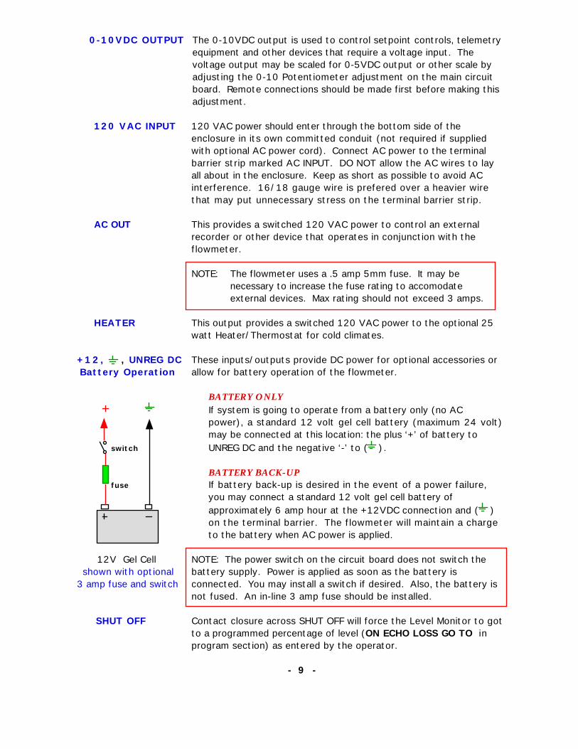
0-10VDC OUTPUT The 0-10VDC output is used to control setpoint controls, telemetry equipment and other devices that require a voltage input. The voltage output may be scaled for 0-5VDC output or other scale by adjusting the 0-10 Potentiometer adjustment on the main circuit board. Remote connections should be made first before making this adjustment.
120 VAC INPUT 120 VAC power should enter through the bottom side of the enclosure in its own committed conduit (not required if supplied with optional AC power cord). Connect AC power to the terminal barrier strip marked AC INPUT. DO NOT allow the AC wires to lay all about in the enclosure. Keep as short as possible to avoid AC interference. 16/18 gauge wire is prefered over a heavier wire that may put unnecessary stress on the terminal barrier strip.
AC OUT This provides a switched 120 VAC power to control an external recorder or other device that operates in conjunction with the flowmeter.
NOTE: The flowmeter uses a .5 amp 5mm fuse. It may be necessary to increase the fuse rating to accomodate external devices. Max rating should not exceed 3 amps.
HEATER This output provides a switched 120 VAC power to the optional 25 watt Heater/Thermostat for cold climates.
+12, , UNREG DC These inputs/outputs provide DC power for optional accessories or Battery Operation allow for battery operation of the flowmeter.
BATTERY ONLY
If system is going to operate from a battery only (no AC power), a standard 12 volt gel cell battery (maximum 24 volt)may be connected at this location: the plus ‘+’ of battery to
switch UNREG DC and the negative ‘-’ to ( ).
BATTERY BACK-UP fuse If battery back-up is desired in the event of a power failure,
you may connect a standard 12 volt gel cell battery of approximately 6 amp hour at the +12VDC connection and ( ) on the terminal barrier. The flowmeter will maintain a charge
to the battery when AC power is applied.
12V Gel Cell NOTE: The power switch on the circuit board does not switch the shown with optional battery supply. Power is applied as soon as the battery is 3 amp fuse and switch connected. You may install a switch if desired. Also, the battery is
not fused. An in-line 3 amp fuse should be installed.
SHUT OFF Contact closure across SHUT OFF will force the Level Monitor to gotto a programmed percentage of level (ON ECHO LOSS GO TO in program section) as entered by the operator.
- 9 -

ADJUSTMENTS AND CONTROLS
There are very few adjustments that can be made on the PDS-360 system. Do not attempt to make any if you do not understand their purpose. To do so may void your warranty and result in a costly service charge. Refer to figure 4 for adjustment locations.
1. Transmitter / Receiver Card
GAIN The gain should always be set before programming begins. Normally the
GAIN setting does not need to be touched. Typical adjustment is set to one half of its turn. If adjustment needs to be made first make certain that the Sensor is plumb to the flow surface. Keep in mind that changes in the GAIN setting may effect the apparent calibration and you may have to offset the calibration under CAL/TEST/...... mode - SENSOR/FLOW SURFACE RANGE in the programming. Too much or too little GAIN may cause the unit to respond to unwanted noise or cause loss of signal.
J1 and J2 J1(FILT)/J2(THRESHOLD), positions 1 is normal selection. Position 2 of JUMPERS J1 and/or J2 will help to filter out unwanted noises. Select position 2
only if meter is in a electrically noisy environment and the meter is erratic. Moving J2 jumper is generally prefered over J1 jumper. Do Not mistaken Sensor mounting problems for electrical noise problems. Sensor mounted to any metalic fittings etc. will cause problems that may not be resolved by GAIN or J1/J2 selections. See Sensor Installation.
XMIT / L2 XMIT is for setting the transmitt frequency (40kHz.) and L2 (tuning coil) for setting the receivers frequency. The XMIT pot is typically set to 1/2 of its turn. Slight adjustments of these settings will affect the gain of the flowmeter and may help minimize electrical noise problems.
Cnt
Shd
Threshold
FiltON
Gain
L21 2 J2
J11
2
trig
echo12
J3
RED
BARE
BLACK
xmit
PC-547 Ultrasonic Xmit / Receive Card
Adjustments shown in their NORMAL position
Figure 4.

2. Main Circuit Board
Refer to Figure 3 for the following adjustments.
4 mA. The 4 mA. adjustment is used to set the 4-20 mA. current output loop to4 mA. This should be set before the 20 mA. adjustment. This will prevent any apparent interaction of the 4 and 20 mA. adjustments. You can Simulate0% output using the TEST ANALOG OUTPUT feature under CAL/TEST/..... mode in the programming to set the 4 mA. output.
20 mA. Adjust the 20 mA. control for 20 mA. output on the 4-20 mA. current output loop. Simulate 100% output using the TEST ANALOG OUTPUT feature found under CAL/TEST/.... mode in the programming.
0-10 VDC Adjust the 0-10 VDC potentiometer for a scaled voltage output. It is best to have the receiving device connected to the terminal barrier when making this adjustment.
DAMP ADJ Adjust clockwise to increase the Analog Output Dampening for steadier chartrecordings.
ON/OFF Applies AC power to the circuit board and AC out to the HEATER and AC OUT on the terminal barrier. Note: this switch does not control battery if connected.
120/220 VAC Install or remove appropriate jumper(s) to change operating voltage to 120 or 220 VAC.
FRONT PANEL
The keypad on the front panel is used for selecting the various RUN MODE indications and program modes of the flowmeter. When in the RUN MODE, press SELECT button for the display type you want. The 4-20 mA. output isnot affected by the selection of any RUN MODE window. Refer to the PROGRAM FLOWCHART on page 16 for navigating through the programming.
The programming of the flowmeter is accomplished by pressing the SELECTbutton until you are asked if you want to GO TO PROGRAM MODE? If youselect YES you will be asked to ENTER YOUR PASS CODE . Enter the PASSCODE using the SHIFT, UP and DOWN buttons. If the wrong PASS CODE is entered, the display will return to the RUN MODES.
Note: The flowmeter leaves the factory with pass code 0000.
Once in the PROGRAM MODES, use the SELECT button to scroll through the various selections, selecting NO/YES where needed. To change any value, use the SHIFT, UP and DOWN buttons. Refer to the PROGRAM FLOWCHART.
- 11 -

LCD DISPLAY
INDICATOR The PDS-360 display is a 2 line, 20 character alpha-numeric display with LED backlighting. All flow information and programming data is indicated by this display.
GPM, MGD Flow may be displayed in GPM (gallons per minute) or in MGD (million gallons per day) units.
TOTALIZER An 8 digit totalizer count indicates the total accumulated flow to date. The total will be equal to the count displayed times the multiplier (i.e. x100) indicated. The multiplier may be programmed under the SET FLOW PARAMETERS.
TYPICAL DISPLAY AND KEYPAD LAYOUT
MGD = 1.20300TOTAL x 10 = 38447
Select Shift Up Down
NO Datalog YES
DEPTH DEPTH indicates the measured HEAD (depth) of water as it passes through the flume or over the weir plate. This reading is used in the equation for the selected primary device to calculate the GPM flow reading and finally atotal accumulated flow.(Depth = ZERO% distance - SENOR to FLOW SURFACE range).Note: if the flow level drops below the ZERO % setting, the DEPTH will be displayed as a negative number.i.e. DEPTH = - 2.34" (means 2.34" below ZERO % level).
LF The letters LF displayed in the top right corner of the display indicate that (Low Flow) the LOW-FLOW SHUT-OFF is activated. When the flow percent calculated
by the flowmeter is below the LOW FLOW SHUT OFF percent setting programmed by the operator, the %, GPM, MGD readings and analog outputs (i.e. 4-20mA) will be forced to zero. The totalizer stops countingat this time. The DEPTH display will continue to indicate the flow depth as measured by the flowmeter.
-12 -

* (asterik) A blinking asterik (*) displayed in the top right corner indicates that the ECHO tracking function is enabled (user selectable). When the asterikblinks erraticly, this indicates the presents of electrical noise or intermittent ECHO return due to turbulence. When the asterik is continuously ON (does not blink), this indicates the flowmeter is searching for a valid or lost ECHO. It is possible the flowmeter will discriminate the ECHO returns for up to 5-10 seconds.
Indicates GPM, MGD, DEPTH of flow and LOW-FLOW is activated % of flow as selected by SELECT button. ECHO tracking is ON
GPM = 000.00 LF* TOTAL x100 = 325476
Indicates TOTAL flow to The multiplier is set in the date in gallons. SET FLOW PARAMETERS mode. Note: the totalizer is disabled when 'LF' (low flow) is displayed on the top line.
TYPICAL RUN DISPLAY
FLOW % FLOW % indicates the percent of flow as found on the 4-20 mA. output.The output is scaled by the SCALE ANALOG OUTPUT under the SET FLOW PARAMETERS mode in programming.
TEMPERATURE The outside temperature at the Sensor is indicated here. The temperature is in degree fahrenheit ±3°. The flowmeter must have a temperature reading to do flow calculations. If the probe is damaged or not used, you must manually turn the probe OFF and enter a temperature under TURN TEMP PROBE ON / OFF in CAL/TEST/...... mode.
Note: Temperature may indicate a few degrees warmer than the ambient air if the sun is shining directly on the sensor.
Indicates % of flow as found on the 4-20 mA. output.
FLOW % = 35.6 % Temperature = 65 deg F
Indicates the fahrenheit temperature at the Sensor
- 13 -

CALIBRATION
All PDS-360 systems are calibrated through the PROGRAM modes. The
operator first installs the Sensor as described and measures the distance from the Sensor face to the ZERO FLOW point (crest) in the flume or weir.The Sensor must be at least 12.0" from the anticipated 100% flow level.
Enter into the PROGRAM MODE by pressing the SELECT button, answering YES when asked GO TO PROGRAM MODE? . Enter the PASS CODE and press SELECT and go to PRIMARY DEVICE mode. Press YES and enter the type and size flow device you have. Next press select and YES when asked SET FLOW PARAMETERS . Enter the measured ZERO FLOW DISTANCE point using the SHIFT, UP and DOWN keys. Press SELECT. Enter the 0-100% SPAN . Refer to the FLOWCHART to help younavigate through the program section. See page 16.
Note: The SPAN will automatically set itself according to SPAN = ZERO DISTANCE setting less12.0". You may change the SPAN to any value that is less then the value displayed. Minimum SPAN is 1.00".
Proceed through the PROGRAM MODE refering to the PROGRAM FLOWCHART for assistance. Change the SCALE ANALOG OUTPUT to scale the analog output (i.e. 4-20 mA.) to a remote recorder if needed.For example, the recorder charts are printed 0-500 (gallons). Set the ANALOG OUTPUT for 000500.00 gallons. This completes the basic calibration.
Changing The Calibration Reference
Take a measurment from the Sensors face to the surface of the flow. Go toCAL/TEST/.... mode in the flowmeter and check the SENSOR/FLOW SURFACE RANGE. This is the actual measurement the flowmeter is making. If the distance is not correct, use the UP or DOWN button to change. Each press of the button is approximately 0.05". This alters the microsecond reference used in the distance calculation to compensate for installation anomalies and atmosphere conditions. DO NOT attempt to correct flow indication unless you are absolutely certain that the instrument is incorrect.Be sure the Sensor has been installed properly over the flumeor weir (see sensor installation), programmed data is
Sensor to Flow Surface correct, Temperature Reading is correct and all cables have Distance been properly connected.
- 14 -

SETTING THE ANALOG OUTPUTS
4-20mA. The 4-20 mA. output can be set by using the TEST ANALOG OUTPUT? function under the CAL/TEST/.... mode. Enter the TEST OUTPUT feature and press SHIFT to simulate 0% (4mA), UP for 50% (16mA)and the DOWN button for 100% (20mA). Simulate 0% and adjust the"4 mA." potentiometer adjustment (figure 3) for 4 mA. output. Simulate 100% and adjust the "20 mA." potentiometer for 20 mA. output.Note: perform the 4 mA. adjustment first to eliminate any interaction between the 4 and 20 mA. adjustments.
0-10VDC This may be adjusted at any time for any scaled voltage output desired up to 10VDC. Example: if full scale output required is 0-5 VDC adjust the 0-10 trim pot for correct voltage out.
SAMPLER AND COUNTER OUTPUTS
The SAMPLER and COUNT outputs are functionally the same but independently programmable under the SETPOINT/RELAY mode. Example: if you need to sample your flow every 1000 gallons you would program the SAMPLER PULSE RATE for 001000. If a remote counter needs to be pulsed you would use EXTERNAL COUNT and program the multiplier i.e enter 000100 for x100. The relay will close for a duration of 250 ms. (milli-seconds = 1/4 sec) when the count is reached. The function will automatically reset itself for next count.The relay contacts are dry contact closures rated 7 amp, 250 VAC.
ALARM SETPOINTS
The PDS-360 has two independently programmed alarm setpoint outputs.The programming is performed under the SETPOINT/RELAY mode. Eachalarm has a separate percent ON and OFF setting for differential control of pump ON and pump OFF or valve open/close control etc. The relay contacts are dry contact closures rated 7 amp, 250VAC.
3 VOLT BATTERY (type CR2325)
This battery is for retaining programmed information and keeping the clock running when power is turned OFF. The battery should last for approximately 8 to 10 years under normal operation. Replace the batteryif it is over 5 years old and the system fails to start-up after attempting the start-up resets as described in the Program Flowchart page 16-17. It will be necessary to remove the processor card above the battery. Referto figure 3. Install a new battery and reinstall the processor card. Start-up the system as described and reset the meter to factory defaults. Proceedto program section and reprogram the flowmeter and setting the clock. The reset to factory defaults may need to be repeated 2 or 3 times to clear the memory properly.
- 15 -
Using The PDS-360 FLOWCHART
OPERATING INSTRUCTIONSWhen power is first applied, the PDS-360 flowmeter will run through its POWER-UPwindows. It should display a greeting informing the user that the settings have not beenchanged; a request that the user should read the instruction manual; the softwarerevision number, copyright notice and manufacturers name. The process takes a fewseconds and will then enter the RUN MODE. The flowmeter will display the windowthat was ON prior to turning power ‘OFF’. To select or scroll through the RUN MODES,use the SELECT button. Each press of the SELECT button takes you to the next window.Selecting any of the RUN MODES will not affect the 4-20 mA. output or any of theprogrammed settings. The flowmeter begins monitoring flow automatically.
To enter the PROGRAM MODE , press the SELECT button until asked GO TOPROGRAM MODE? . Press ‘YES’. You will be asked for the PASS CODE before youcan enter into the PROGRAM MODES . The pass code is 0000 when it leaves thefactory and will remain this until you change it. Press SELECT. If you like to changethe code at this time, use the SHIFT, UP and DOWN buttons to enter your new pass codethen press SELECT. This stores your new code. You now have access to the programsection. If the incorrect pass code is entered, you will be returned to the RUN MODE.
Once you entered the PROGRAM MODE you can scroll through it by pressing theSELECT button. The SELECT button performs three functions: 1] NO, 2] ENTER and 3]NEXT WINDOW. Use the SHIFT, UP and DOWN buttons to change the values in eachwindow as needed. The DOWN button is used to select YES when data values are notdisplayed.
RESETTING THE FLOWMETERIf the SELECT button is held when power is applied, then released, the user will haveaccess to the flowmeters reset functions. The user may reset the flowmeter to factorydefaults. This reset will set the pass code to ‘0000’. The user may also reload thesaved USER PRESETS for quick resetting/programming of the flowmeter (providedthe user SAVED the settings when prompted to in the programming). This function canhelp recover from a processor crash or lock-up. Both of these resets do not affect thetotalizer or data log. The user may proceed to resetting the totalizer and /or data log inthe PROGRAMMING section.
IF THE FLOWMETER SHOULD LOCK-UP or CRASHIt is possible that the flow of the program may be interrupted by some external eventsuch as lightning, testing back-up generators or some other anomaly on the AC orSensor input that may cause the flowmeter to crash or lock-up. Turning power OFFand waiting approximately 10 seconds before turning the meter back ON maycorrect/unlock the meter. If not, it may be necessary to perform a RESET using theSELECT button mentioned above. Resetting to factory defaults is considered a hard resetand it will be necessary to reprogram the meter after this reset. Resetting to USERPRESETS is prefered. You can first do a FACTORY DEFAULT reset and then a USERPRESETS if you like. You should not need to reset the totalizer or data log.
- 16 -

The PDS-360 PROGRAM FLOWCHART 1
GPM = 560.20 * Total x 10 = 231445
MGD = 0.80600 * Total x 10 = 231445
Depth = 23.70 in. *GPM = 560.20
- 17 -
RUN MODE
GO TO PROGRAM MODE ?>NO YES
Enter Your Pass Code 0000
Change Pass Code ? 0000
Shift Up Down
Shift Up Down
Wrong
Set Primary Device ? >NO YES
Up Down
NO
The PASS CODE must be enteredcorrectly before you can proceedto the Program Modes. If the wrong code is entered, you will be returned to the RUN MODE.
The Flowmeter leaves the factorywith PASS CODE 0000. PressSELECT to continue and enter the Program section.
If you like, you can change the PASS CODE at this time.
REMEMBER YOUR CODE !!!
Asterisk (*) indicatesTracking is Activated Select Flume/Weir
Parshall Flume
Select Size 2 in. PARSHALL
Selections are:1] Parshall2] Palmer-Bowlus3] Leopold Lagco4] V-Notch Weir5] Rect Weir W/end6] Rect Weir no end7] User Defined a] max flow head b] GPM at max head c] Exponent
To SET FLOWPARAMETERS
PRIMARY DEVICE
Flow % = 65.37 % *Temperature = 72 F
CONTROL ELECTRONICS Model PDS-360
Open-Chan Flowmeter REV xx
Select
POWER UP Holding and then releasing the SELECT button when power is applied will access the metersRESET functions.
Turn Power ON
Hello ! Meter Reset Settings NOT Changed
Please Read Your Instruction Manual !
no buttonheld
Rv X, Copyight 1997Control Electronics
Rv X, Copyight 1997Control Electronics
Reset to Defaults ? >NO YES
Rst to USER PRESETS ? >NO YES
Reset the Flowmeterto Factory Defaults.
Reset the flowmeterto USERS savedPRESETS.
Press the DOWN button to read DEPTHin inches orfeet.
Shift Up Down
Enter # of Weirs 01
If #4-7 is selected, you willbe asked for the number ofWeirs you are monitoring.The GPM and Total will bemultiplied by this value.
Note: Shadowed Windows must be set by the user. All others are optional.

2 The PDS-360 PROGRAM FLOWCHART
Set Flow Parameters>NO YES
- 18 -
PROGRAM MODE
Set Span (max. head)Span = 16.00 in.
Scale Analog Output100% = 00500.00 GPM
Average Readings Average Every 10
Zero Flow Distance ?Zero % = 28.00 in.
Low Flow Shut Off % OFF = 02%
On Echo Signal LostGo To 00% of scale
Data Log Sample RateLog Every 05 Minutes
ZERO Flow Distance is the distance from the Sensor face to the ZERO% flow point (crest) of the flow device. Refer to Sensor Installation.
SPAN is auto set to SPAN = ZERO% - 12.0” if you had changed the ZERO % setting in the previous window. You may change the SPAN to a smaller value, but not greater.
This scales the analog output. i.e.: the circular chart recorder is set for 0-500 GPM. Set output for 00500.00 GPM.
Outputs and flow indications will go to ZERO when flow is below SHUT OFF % setting. This works in conjunction with SCALE ANALOG OUTPUT.Note: if 100% ANALOG OUTPUT above is set too high, the SHUT OFF may prevent flow readings.
Sets the SAMPLE RATE for Data Logging. i.e.: 05 minutes indicates that every 5 minutes the FLOW will be logged and time stamped. If set to 00 minutes, data log is disabled.
RED shadowed Windows indicatethat these parameters MUST be set
by the operator to calibrate the flowmeter to his/her application. Allother settings are optional to the user.
Note:
NO
Average Readings helps to Damp the display. As shown, The flowmeter will take 10 measurements and average the readings before displaying. An average of 4 equals approximately 1 second before updating the display. Average of 8, approximatly 2 seconds and so on.
If the ECHO Signal is lost, the flow meters display and outputs will go to the percent entered. Relay outputs etc. will respond accordingly. 00% = Stay at last reading.
To SETPOINTS/RELAYS
Meter has been RESETmodel PDS-360 RVxx
Press and hold the DOWN button at anytime for 2 seconds will RESET the meter with no change to data and display model# and software Rv#.
To Last RUN mode
After 2 seconds meter will display....
Totalizer Multiplier1 count = 1 gal.
Select the times factor for the Totalizer in total gallons. Select x1, x10, 100, x1000.
Signal Filtering......Filtering = 05%
Applies filtering to receivedsignal to filter out noisespikes etc. CAUTION: 80 to100% filtering could removedistant echo signals.
Values are shown in FACTORY DEFAULTS

The PDS-360 PROGRAM FLOWCHART 3
Setpoint /Relay mode>NO YES
- 19 -
SET POINT MODE
Setpoint # 1 ON ON % = 05 %
Setpoint # 1 OFF OFF % = 15 %
Setpoint # 2 ON ON % = 90 %
Setpoint # 2 OFF OFF % = 85 %
Sampler Pulse Rate 000000 gallons
External Count Pulse 000000 gallons
Two (2) independent setpoints are available withindependent ON/OFF percent trip points. This allows fordifferential control of a pump, valve etc. or to preventrelay chatter in turbulent flow conditions.
Two (2) independent programmable pulse outputs are available. The Sampler Pulse will generate a relay pulse closure of 250 ms. duration at the SAMPLE output relay each time the amount of gallons set is counted by the totalizer. This output is usually connected to a remote Sampler. The External Count Pulse output is identical in function as the Sampler Pulse output. It may be used to pul;se a second sampler or remote counter. Once settings are changed, the function will reset itself with the new data.
CAL/TEST/MISC/TIME modeNO

4 The PDS-360 PROGRAM FLOWCHART
- 20 -
Cal/Test/Misc/Time>NO Yes
Test Analog Output ?> NO YES
Sensor/Flow SurfaceRange = 06.42 in.
Enter Ambient Temp 070 deg. F
Analog Output = 0 %Done 0% 50% 100%
Set the Time/Date for Data Logging
Test the ANALOG outputs and set the4-20 mA. adjustments if needed.
If the temperature probe is not being used or is defective, you must enter a temperature for the flowmeter to make its calculations. Enter a temperature that represents the averagetemperature out at the Sensor.
This indicates the distance from the Sensors face to the flow surface as measured by the meter. If incorrect, use the UP/DOWN buttons to change. Each press of the button = approx. 0.05”. Be sure the Temperature indication is reasonably correct in RUN MODE first. See CALIBRATION section for more information.
Temp Probe is........... ON
SHIFT UP DOWN
Turn Tracking ON ? >NO YES
Time Date12:00 AM 11/15/97
Set Communications ?>NO YES
SHIFT UP DOWN
Save as Presets ?>NO Yes
NO
Set RS-232 Baud Rate 2400
UP DOWN
Set the RS-232 output Baud Rate to 1200, 2400 or 9600
Turn the AUTO tracking function ON in turbulent or noisy environments. An asterisk (*) will appear in the upper right hand corner of the display indicating that it is activated. The ‘*’ will flash steadily when locked onto ECHO return and will be erratic or ON steady when searching for or discriminating the ECHO.
Presets are Saved! Thank You
NO
Return to RUN modes
Once you set all the required parameters, you may save them as PRESETS. If the meter crashes or loses the programming, you can restore the presets quickly as described at POWER-UP.
Reset the Totalizer?>NO YES
Select YES to ZERO Totalizer
Set ID# of Flowmeter FT-0000
SHIFT UP DOWN
SHIFT UP DOWN
Setup Data Download?>NO YES
Download Data to......>Printer PC
Type Printer>Serial Parallel
60 entries per page Print 01 pages
Print Data with Plot>NO YES
SHIFT UP DOWN
Set 4 digit ID number
UP DOWN
Set Com Address Com Addr = ‘A’
Set the Communication Address‘A-Z’ (N and Y are reserved)for PC/Laptop communication
UP DOWN
OFF
Reset the Data Log?>NO YES
Sensor RING Time....... 07.53 inches
Blanking Distance....... 25.32 inches
SHIFT
UP DOWN
Select YES to reset Data Log
MISC MODE

The PDS-360 PROGRAM FLOWCHART 5
View Data Log ?>NO YES
- 21 -
Press SHIFT in RUN mode
View Data by>Day Entries
UP/DN to change DAYSel =DONE Shift=MORE
Date: 11/15/97Total = 24356
Date: 11/15/97Avg GPM = 364.23
Time: 10:23 AMMin GPM 205.21
Time: 05:36 PMMax GPM 460.44
UP/DN to change TimeSel =DONE Shift=AUTO
09:45 AM 11/16/97Avg GPM = 73.52
Return to RUN mode
SHIFT
UP DOWN
UP DOWN
UP DOWN
UP DOWN
UP DOWN
Press SHIFT for ON/OFF of AUTO advance by 10.UP/DOWN buttons set direction.
Viewing the Data Log
Select either discrete logged entries orDaily Entries
Reminder of button functions. UP/DOWNto change the Date or Time; SELECT toexit Data View and SHIFT for more info.
Display the Total gallons reading for day indicated.
Use the UP/DOWN button to changeday. 31 days are available with autowrap around.
Press SHIFT to see Average GPM forday indicated. UP/DOWN to change day.
Press SHIFT for more info. Minimumand Maximum GPM’s with Time of occurrence are displayed. Pressing UP or DOWN will advance tothe next day.
Viewing individual Entries. Pressingthe UP or DOWN button will advanceto the next data indicating the time and date.Pressing SHIFT will advance the databy 10 entries automatically. UP/DOWNsets the direction. Auto advance isapproximately every 5 seconds.Pressing SHIFT again will turn offAuto function.
Meter has been RESET
If display should scramble, holding the DOWN button at anytime for 2 seconds will RESET the meter with no change to data.
To Last RUN mode

6 The PDS-360 PROGRAM FLOWCHART
Print Daily Readings... >NO YES
- 22 -
Press UP button when in RUN mode
Print Data Log.........>NO YES
Return to RUN mode
Data Log to Printand/or Download to PC
Print Data ........>NOW AUTO
SHIFT UP DOWN
Print Flow Data ........>NOW AUTO
Will AUTO Print Flow every 05 minutes
Print How Many Days? Print Past 05 days
Will AUTO Print Flowfor Day at MIDNIGHT
Select YES for Dailysummary of flow. Upto 31 days is available.
Select YES for sampledlogged data
Print data NOW or AUTO
If NOW is selected: Print # of pages in setup Print up to 31 daysof flow summary w/totals.Printing begins when the SELECT button is pressed.
If AUTO is selected, displaywill show for 5 seconds thenwill print data as described automatically.
NOTE
keypad is disabled when printing starts. Hold the DOWN button for 2 seconds to cancel printing.
You must first set-up communication parameters underCAL / TEST / MISC / TIME section of program before printingdata.
1]
2]
Making your selections then pressing the SELECT button will begin the printingor downloading to a PC.Connect your PC’s COM 1 port to the RS-232 output on the flowmeter for downloading. The PDS-360 will download data in ASCII format to any standard communication package such as found in HYPER TERMINAL in WINDOWS 95/98 etc. Data may be saved to file, printed out or imported into a spread sheet for graphing and analysis.
Will begin to print DATA.Will print number of pagesselected in Communicationssetup with PLOT if selected.


Using the RS-232 Communication Output Port
The Operator may choose to communicate with the flowmeter using their PC or Laptop computer in order to download the logged data for further viewing and analysis. This may be accomplished by using any standard communication software package such as WINDOWS HYPER-TERMINAL, PROCOM etc. All data downloaded is in ASCII format. Each line of data is terminated by a CR (carrage return) and line feed. Downloading of flow data may be initiated from the flowmeter using the PRINT functions (see FLOWCHART page 22 ) or by the PC / Laptop computer. Connect your communication cable to the RS-232 terminal barrier as indicated (see page 26).
In order to successfully download data by either method, you must first match the communication settings in both the flowmeter and the PC. The flowmeter sends data in one of three baud rates - 1200, 2400 (default) or 9600 baud. The baud rate is set in the flowmeter by the user under the CAL program section. You may set the flowmeter ID# at this time and whether data will be sent in SERIAL, PARALLEL or PC format (required if you are going to initiate downloading from the flowmeter only).
PC’s Communication SettingsYou should set the PC parameters to match the flowmeters baud rate, no parity, 8 bit, 1 stop bit, XON/XOFF disabled. (i.e. 2400,N,8,1)
Serial Output (printer Only)This mode is used to send data to a serial printer and is fairly slow, because a 3 second delay is performed by the flowmeter for each line sent to allow the printer time to print the line. Be sure to set the serial printers baud rate to match the flowmeters. Use the Tx connection on the RS-232 terminal barrier, not the ‘serial’ output connection. NOTE: The ‘serial out’ on the terminal barrier is for special purposes only. Do not use for communications.
Parallel Output (printer only)This mode is used for downloading to a PC and sending data to a parallel matrix printer when a serial to parallel converter is used. Data is sent much faster using this selection. Use the Tx output connection, not the ‘serial’ output, when connecting to a PC.
PC OutputThis mode is identical to PARALLEL output except it is a little faster.
To Initiate Downloading from the Flowmeter:
Use this method if your PC software does not support 2 way communication.Set your software in the PC to ‘begin capture’ and save to file. (See your PC/software owners manual for assistance).Select the PRINT function on the flowmeter (press the UP button while in the RUN modes) and select data type to send. i.e. 31 day summary or individual time stamped entries with or without plot . See page 22 of flowmeters manual for assistance.Once download begins, it will continue until completed or interrupted by holding the DOWN button for 2 seconds. Once data has been downloaded and saved to file, you may import it into a spread sheet for graphing and analysis or reformat the data in a word processor for printing etc.
- 24 -

To Initiate Download from a PC or Laptop:
Communication is kept simple. Connect the communication cable to the RS-232 connector onthe PC board (see page 26). Open your PC communication software (i.e. HYPER-TERMINAL), then:
1] type an upper case ‘A’ (= com addr as set by user)to get the flowmeters attention .2] Flowmeter should respond with a greeting, model number and a short menu.
Hello!PDS-360 Ultrasonic FlowmeterEnter Download Selection Type....
1] 31 Day Flow Summary2] Data Entries with plot3] Data Entries without plot4] Auto Data Entry5] Terminate Auto Data Entry [#4 above]6] Terminate Communication7] Reset the Data Log
Hit ENTER to interrupt Download Selection number 2 and 3.
Your Choice .......>
Once communication is established, you may select type of download by typing the number of the selection.
Selection 1: will download the past 31 day flow summary with DATE, MIN/MAX GPM with TIME, AVG GPM and TOTALS.
Selection 2: will download data entries as logged, time stamped with plot. This download could take a few minutes depending on baud rate and data size.
Selection 3: Same as number 2, but without plot.Selection 4: allows the PC to capture the data as it is logged. This allows monitoring
the flow as it occurs. Communication is suspended until a data stream is sent. Data will be sent in intervals equal to the LOG SAMPLE RATE programmed by the user. The keypad is enabled at this time.
Selection 5: will terminate selection number 4, but only after you obtain the flowmeters attention once again by typing an upper case ‘A’ and ENTER.
Selection 6: terminates communication.Selection 7: Resets the Data Log and terminates communication.
Please note:1] while the flowmeter is downloading data, the flowmeters keypad is disabled except for the DOWN button which will interrupt the downloading if held for 2 seconds. The flowmeter continues to monitor and total the flow during communication and downloading to a PC. 2] Hit ‘shift’ key at any time during selection 2 & 3 above to interrupt the download.3] All downloads begin with the most recent data.4] All downloads begin with a header indicating model number, ID number, date and type of download.5] Once the flowmeters ‘attention’ has been acquired, the user has approximately 2 minute to respond or the flowmeter will automatically terminate communication. This is to prevent communication port lockup and flowmeter keypad lockup.6] The optional RS-485 output allows communication with the flowmeter up to 4000 feet away. It does require that the receiving end has an RS-485 receiver.
- 25 -