Embed Size (px)
Citation preview

i
TABLE OF CONTENTS
1. Introduction .............................................................................................. 1
2. Operation ................................................................................................... 2
2.1 Installation ................................................................................................ 2
2.2 Connecting the ATMOS 22 .......................................................................... 4
2.2.1 Connecting to a ZENTRA, EM60, or Em50 Family Data Logger .......... 4
2.2.2 Connecting to a Non-METER Logger ................................................ 5
2.3 Communication ......................................................................................... 6
3. System ......................................................................................................... 7
3.1 Specifications ............................................................................................ 7
3.2 Anemometer .............................................................................................. 9
3.3 Temperature Sensor ................................................................................. 10
3.4 Tilt Sensor ................................................................................................ 10
3.5 Wind Speed and Direction Theory ............................................................ 11
3.6 Limitations .............................................................................................. 12
3.6.1 Snow and Ice Accumulation ........................................................... 12
3.6.2 Heavy Rain and Strong Wind .......................................................... 12
4. Service ....................................................................................................... 13
4.1 Calibration ............................................................................................... 13
4.2 Cleaning and Maintenance ....................................................................... 13
4.3 Troubleshooting ....................................................................................... 14
4.4 Customer Support.................................................................................... 15
4.5 Terms and Conditions .............................................................................. 16
References .................................................................................................... 18
Index ................................................................................................................. 19
14586-01
1.6.2018
1
INTRODUCTION
1. INTRODUCTIONThank you for choosing the ATMOS 22 Ultrasonic Anemometer from METER Group.
The ATMOS 22 Ultrasonic Anemometer is designed for continuous monitoring of wind speed
and direction (Section 3). A robust, no moving parts design that prevents errors because of
wear or fouling make the ATMOS 22 ideal for long-term, remote installations.
Applications of the ATMOS 22 are listed below:
• Weather monitoring
• Microenvironment monitoring
• In-canopy wind measurement
• Spatially-distributed environmental monitoring
• Wind profiling
• Crop weather monitoring
• Weather networks
Additional advantages include its low-power design that supports battery-operated data
loggers, and the SDI-12 three-wire interface. A tilt sensor warns the user of out-of-level
condition, and no configurations are necessary.

2
ATMOS 22
2. OPERATIONPlease read all instructions before operating the ATMOS 22 to ensure it performs to its
full potential.
SAFETY PRECAUTIONS
METER sensors are built to the highest standards. Misuse, improper protection, or improper
installation may damage the sensor and possibly void the manufacturer’s warranty.
Before integrating ATMOS 22 or other METER sensors into a system, make sure to follow
the recommended installation instructions and have the proper protections in place to
safeguard sensors from damage.
2.1 INSTALLATIONFollow the steps listed in Table 1 to set up the ATMOS 22 and start collecting data.
Table 1 Installation
Tools Needed
Wrench 13 mm (1/2 inch)
Secure mounting location
Mount meteorological stand
pole in cement
tripod
Diameter: 31.8–50.8 mm, 1.25–2.00 inch
NOTE: Smaller mounts are compatible if washers are added to the V-bolt (not included).
Standard pipe sizes that are compatible are 1.00-, 1.25-, and 1.50-inch diameter pipes.
Square tubing with a width of 1.25 to 2.00 inches or T-posts can also work as mounting
options.
Preparation
Consider the Surroundings
Avoid obstructions.
Ensure that site selection is far from wind obstruction.
Conduct System CheckVerify that the ATMOS 22 reads within expected ranges (Section 3).
Adjust Pole HeightMounting height can be adjusted based on the specifi c application for the ATMOS 22.
19
INDEX
INDEX
A
applications 1
C
calibration 13
cleaning 13
components 11
connecting the ATMOS 22 4
connections
customer support 15
D
data acquisition system 3
See also installation,
connecting the ATMOS 22
I
installation 2
connecting the ATMOS 22 4–6
mounting 3
tools required 2
L
limitations 12
M
maintenance 13
measurements 7–9
air temperature 10
tilt 7, 10
wind direction 7, 9
wind gust 7, 9
wind speed 7, 9
S
sensors
anemometer 9
temperature sensor 10
tilt 10
specifi cations 7–10
cable length 7
compliance 9
dimensions 7
electrical and timing characteristics 8
measurement specifi cations 7
T
terms and conditions 16–17
theory
air temperature 10–11
temperature sensor 10
wind direction 9, 11–13
wind gust 9
wind speed 9, 11–13
troubleshooting
ATMOS 22 not responding 14
no wind speed 14
precipitation measurements
in frozen conditions 12
wind speed and direction errors
during heavy rain and strong wind 12
Z
ZENTRA
ZENTRA Cloud 4
ZENTRA Utility 4
18
ATMOS 22
REFERENCES
Campbell GS, Unsworth MH. 1979. An inexpensive sonic anemometer for eddy correlation.
J Appl Meteor. 18:1072–1077.
3
OPERATION
Table 1 Installation (continued)
Mounting
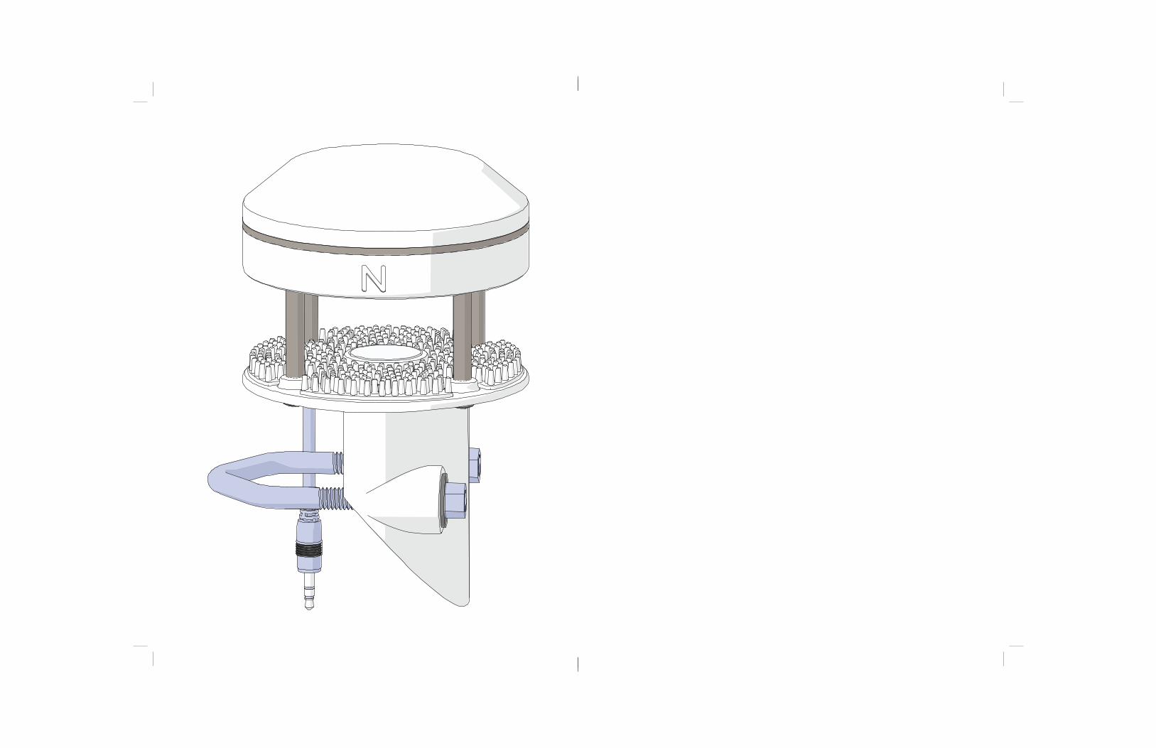
Install on Mounting PoleThe ATMOS 22 is fi tted with a V-bolt, allowing it to be mounted on top of most posts, poles, tripods, etc.
Mount Toward True NorthThe ATMOS 22 must be oriented correctly for accurate wind direction measurements. An N engraved on the side of the instrument should be oriented to point true north (not magnetic north).
Level the SystemUse the bubble level underneath the ATMOS 22 or a ProCheck display to level the anemometer. The angle of the mounting pole may need to be adjusted or shims added to the ATMOS 22 pole interface to achieve level.
Secure the SystemUse a wrench to tighten the bolts, securing the ATMOS 22 fl at and tight against the top of the stand.
Connecting
Plug Sensor into Data Acquisition SystemConnect the 3.5-mm stereo plug connector into a ZENTRA-, EM60-, or Em50-family of data loggers.
Confi gure it to read the ATMOS 22 (refer to Section 3).
VerifyUse the SCAN function in the software to show a list of ATMOS 22 readings. Verify that these readings are within expected ranges.
Third Party Data LoggersTo connect to a non-METER data logger, see the ATMOS 22 Integrator Guide.
4
ATMOS 22
Table 1 Installation (continued)
Protecting Cables
Improperly protected cables can lead to severed cables or disconnected sensors. Cabling issues can be caused by many factors such as rodent damage, driving over sensor cables, tripping over the cable, not leaving enough cable slack during installation, poor sensor wiring connections.
Relieve Cable Strain
To relieve strain on the connections and prevent loose cabling from being inadvertently snagged, gather and secure the cables travelling between the ATMOS 22 and the data acquisition device to the mounting mast in one or more places.
Prevent Rodent Damage
Install cables in conduit or plastic cladding when near the ground to avoid rodent damage.
Secure Excess Cable
Tie excess cable to the data logger mast to ensure cable weight does not cause sensor to unplug.
2.2 CONNECTING THE ATMOS 22The ATMOS 22 Ultrasonic Anemometer works most efficiently with ZENTRA-, EM60-, or
Em50-family data loggers. However, this system will not work with legacy data loggers
(Decagon Em5, Em5B).
2.2.1 CONNECTING TO A ZENTRA, EM60, OR EM50 FAMILY DATA LOGGERThe ATMOS 22 works seamlessly with ZENTRA, EM60, or Em50 data loggers. Logger
configuration may be done using either ZENTRA Utility (desktop and mobile) or ZENTRA
Cloud (for cell-enabled ZENTRA data loggers).
1. Plug the 3.5-mm stereo plug connector into one of the sensor ports.
2. Once the ATMOS 22 has been connected to a ZENTRA, EM60, or Em50 data logger,
confi gure the logger port for the ATMOS 22.
3. Set the measurement interval.
Download ATMOS 22 data from a ZENTRA, EM60, or Em50 logger using either ZENTRA
Utility or ZENTRA Cloud.
The standard station with a 3.5-mm stereo plug connector (Figure 1) connects to and is
configured with a ZENTRA, EM60, or Em50 data logger.
17
SERVICE
WARRANTIES. The Seller warrants all equipment manufactured by it to be free from defects
in parts and labor for a period of one year from the date of shipment from factory. The liability
of the Seller applies solely to repairing, replacing, or issuing credit (at the Seller’s sole
discretion) for any equipment manufactured by the Seller and returned by the Buyer during
the warranty period. SELLER MAKES NO SEPARATE OR OTHER WARRANTY OF ANY NATURE
WHATSOEVER, EXPRESS OR IMPLIED, INCLUDING THE WARRANTY OF MERCHANTABILITY
OR FOR A PARTICULAR PURPOSE. There shall be no other obligations either expressed or
implied.
LIMITATION OF LIABILITY. Seller will not be liable to the Buyer or any other person or entity
for indirect special, incidental, consequential, punitive, or exemplary damages in connection
with this transaction or any acts or omissions associated therewith or relating to the sale
or use of any goods, whether such claim is based on breach of warranty, contract, tort, or
other legal theory and regardless of the causes of such loss or damages or whether any other
remedy provided herein fails. In no event will the Seller’s total liability under this contract
exceed an amount equal to the total amount paid for the goods purchased hereunder.
WAIVER. In the event of any default under or breach of the contract by the Buyer, the Seller
has the right to refuse to make further shipments. The Seller’s failure to enforce at any time
or for any period of time the provisions of this contract will not constitute a waiver of such
provisions or the right of the Seller to enforce each and every provision.
GOVERNING LAW. The validity, construction, and performance of the contract and the
transactions to which it relates will be governed by the laws of the United States of America.
All actions, claims, or legal proceedings in any way pertaining to this contract will be
commenced and maintained in the courts of Whitman County, State of Washington, and the
parties hereto each agree to submit themselves to the jurisdiction of such court.
SEVERABILITY. If any of the Terms and Conditions set out in this contact are declared
to be invalid by a court, agency, commission, or other entity having jurisdiction over the
interpretation and enforcement of this contract, the applications of such provisions to
parties or circumstances other than those as to which it is held invalid or unenforceable
will not be affected. Each term not so declared invalid or unenforceable will be valid
and enforced to the fullest extent permitted by law and the rights and obligations of the
parties will be construed and enforced as though a valid commercially reasonable term
consistent with the undertaking of the parties under the order has been substituted in
place of the invalid provision.
SET-OFF. The Buyer may not set-off any amount owing from the Seller to the Buyer against
any amount payable by the Buyer to the Seller whether or not related to this contract
16
ATMOS 22
4.5 TERMS AND CONDITIONSCONTRACT FORMATION. All requests for goods and/or services by METER Group, Inc. USA
(METER) are subject to the customer’s acceptance of these Terms and Conditions. The
Buyer will be deemed to have irrevocably accepted these Terms and Conditions of Sale
upon the first to occur of the Buyer’s issuance of a purchase order or request for goods or
services. Unless expressly assented to in writing by METER, terms and conditions different
are expressly rejected. No course of dealing between the parties hereto shall be deemed to
affect or to modify, amend, or discharge any provisions of this agreement.
PRICES AND PAYMENT. Invoice prices will be based upon METER prices as quoted or at
METER list price in effect at the time an order is received by the Seller. Prices do not include
any state or federal taxes, duties, fees, or charges now or hereafter enacted applicable to the
goods or to this transaction, all of which are the responsibility of the Buyer. Unless otherwise
specified on the invoice, all accounts are due and payable 30 days from the date of invoice.
Unpaid accounts extending beyond 30 days will be subject to a service charge of 2% per
month (24% per annum). Should Seller initiate any legal action or proceeding to collect on
any unpaid invoice, Seller shall be entitled to recover from Buyer all costs and expenses
incurred in connection therewith, including court costs and reasonable attorney’s fees.
RISK OF LOSS AND DELIVERY TITLE. Liability for loss or damage passes to the Buyer when
the Seller delivers the goods on the Seller’s dock or to the transporting agent, whichever
occurs first. The Seller has the right to deliver the goods in installments. Shipping and
delivery dates communicated by the Seller to the Buyer are approximate only.
SHIPMENT. In the absence of specific shipping instructions, the Seller, if and as requested
by the Buyer, will ship the goods by the method the Seller deems most advantageous. Where
the Seller ships the goods, the Buyer will pay all transportation charges that are payable on
delivery or, if transportation charges are prepaid by the Seller, the Buyer will reimburse the
Seller upon receipt of an invoice from the Seller. The Buyer is obligated to obtain insurance
against damage to the goods being shipped. Unless otherwise specified, the goods will be
shipped in the standard Seller commercial packaging. When special packing is required or, in
the opinion of the Seller, required under the circumstances, the cost of the special packaging
shall be the responsibility of the Buyer.
INSPECTION AND ACCEPTANCE. Goods will be conclusively deemed accepted by the
Buyer unless a written notice setting out the rejected goods and the reason for the
rejection is sent by the Buyer to the Seller within 10 days of delivery of the goods. The
Buyer will place rejected goods in safe storage at a reasonably accessible location for
inspection by the Seller.
CUSTOM GOODS. There is no refund or return for custom or nonstandard goods.
5
OPERATION
GroundData
Power
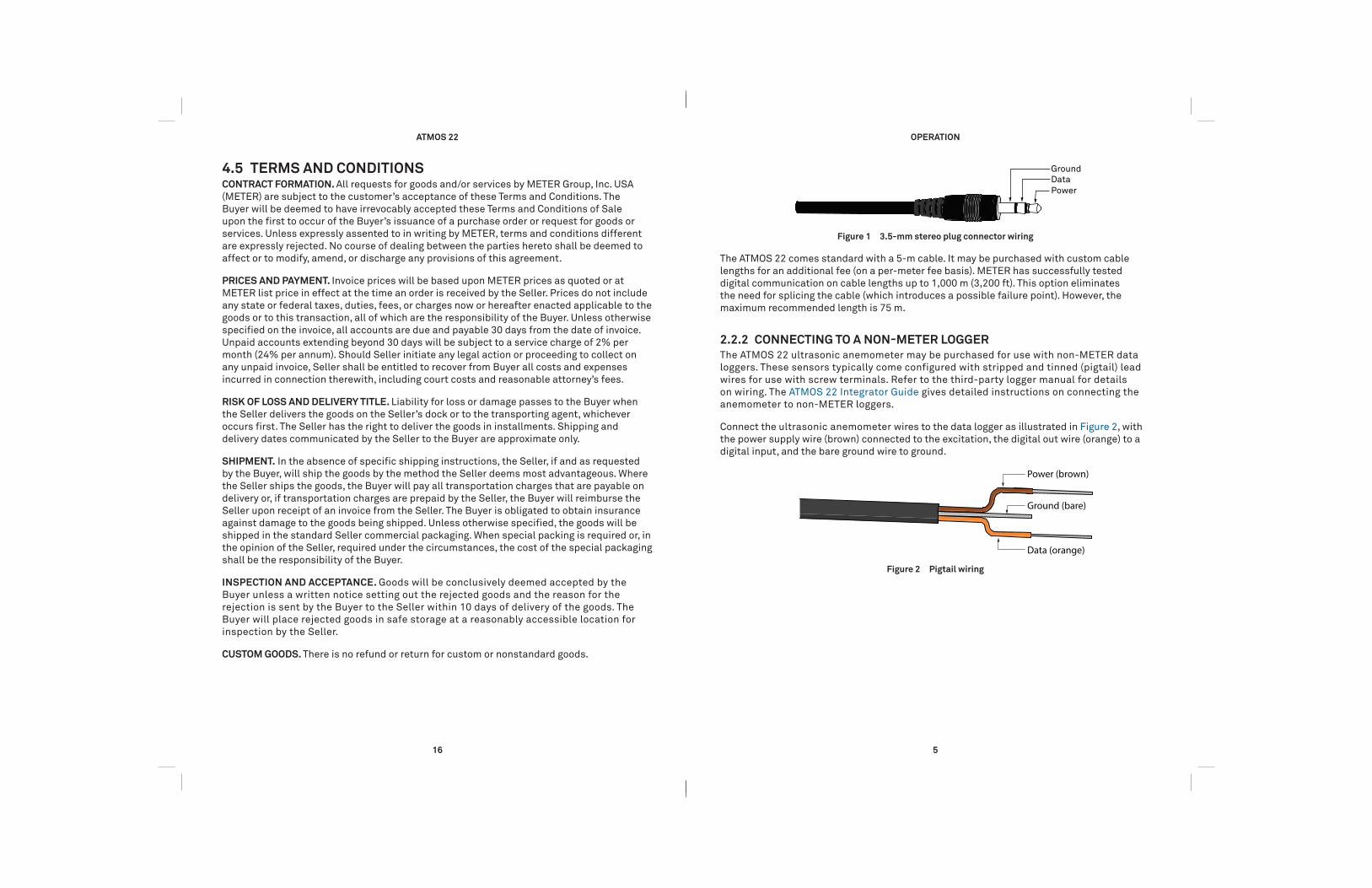
Figure 1 3.5-mm stereo plug connector wiring
The ATMOS 22 comes standard with a 5-m cable. It may be purchased with custom cable
lengths for an additional fee (on a per-meter fee basis). METER has successfully tested
digital communication on cable lengths up to 1,000 m (3,200 ft). This option eliminates
the need for splicing the cable (which introduces a possible failure point). However, the
maximum recommended length is 75 m.
2.2.2 CONNECTING TO A NON-METER LOGGERThe ATMOS 22 ultrasonic anemometer may be purchased for use with non-METER data
loggers. These sensors typically come configured with stripped and tinned (pigtail) lead
wires for use with screw terminals. Refer to the third-party logger manual for details
on wiring. The ATMOS 22 Integrator Guide gives detailed instructions on connecting the
anemometer to non-METER loggers.
Connect the ultrasonic anemometer wires to the data logger as illustrated in Figure 2, with
the power supply wire (brown) connected to the excitation, the digital out wire (orange) to a
digital input, and the bare ground wire to ground.
Ground (bare)
Data (orange)
Power (brown)
Figure 2 Pigtail wiring
6
ATMOS 22
Switched
3.6–15 VDC
Digital
In
Data Logger
G
Data(orange)
Ground(bare)
Power(brown)
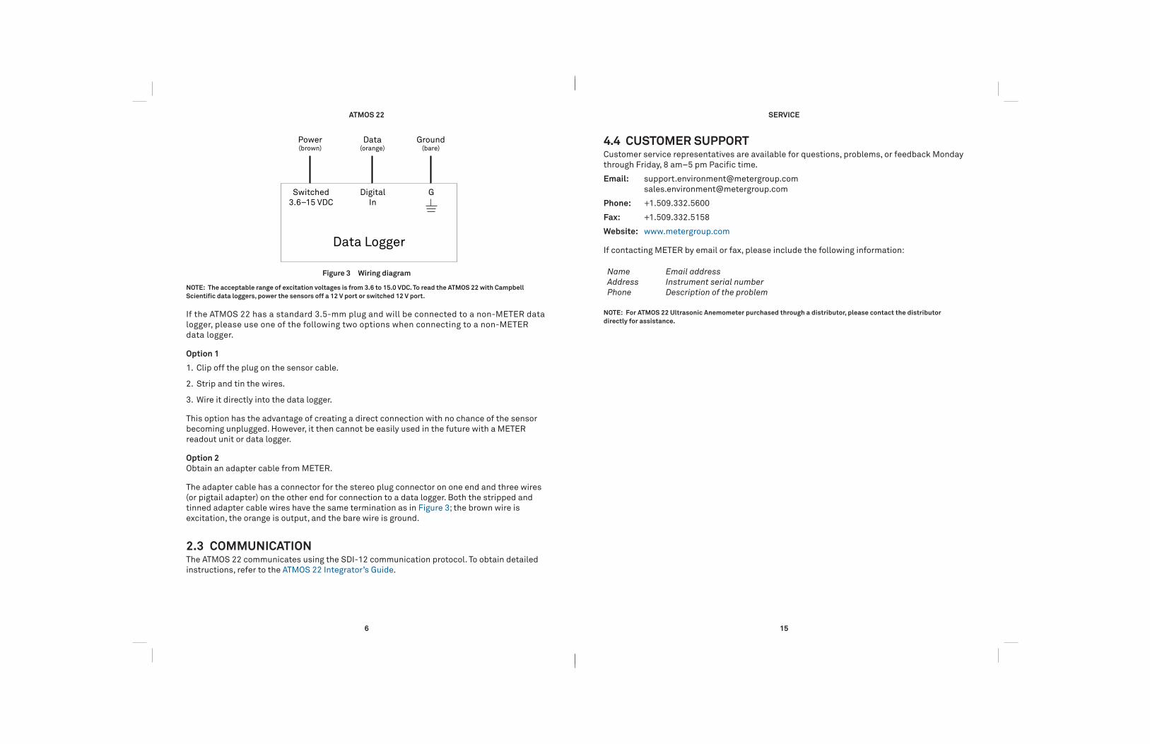
Figure 3 Wiring diagram
NOTE: The acceptable range of excitation voltages is from 3.6 to 15.0 VDC. To read the ATMOS 22 with Campbell
Scientific data loggers, power the sensors off a 12 V port or switched 12 V port.
If the ATMOS 22 has a standard 3.5-mm plug and will be connected to a non-METER data
logger, please use one of the following two options when connecting to a non-METER
data logger.
Option 1
1. Clip off the plug on the sensor cable.
2. Strip and tin the wires.
3. Wire it directly into the data logger.
This option has the advantage of creating a direct connection with no chance of the sensor
becoming unplugged. However, it then cannot be easily used in the future with a METER
readout unit or data logger.
Option 2
Obtain an adapter cable from METER.
The adapter cable has a connector for the stereo plug connector on one end and three wires
(or pigtail adapter) on the other end for connection to a data logger. Both the stripped and
tinned adapter cable wires have the same termination as in Figure 3; the brown wire is
excitation, the orange is output, and the bare wire is ground.
2.3 COMMUNICATIONThe ATMOS 22 communicates using the SDI-12 communication protocol. To obtain detailed
instructions, refer to the ATMOS 22 Integrator’s Guide.
15
SERVICE
4.4 CUSTOMER SUPPORTCustomer service representatives are available for questions, problems, or feedback Monday
through Friday, 8 am–5 pm Pacific time.
Email: [email protected]
Phone: +1.509.332.5600
Fax: +1.509.332.5158
Website: www.metergroup.com
If contacting METER by email or fax, please include the following information:
Name
Address
Phone
Email address
Instrument serial number
Description of the problem
NOTE: For ATMOS 22 Ultrasonic Anemometer purchased through a distributor, please contact the distributor
directly for assistance.
14
ATMOS 22
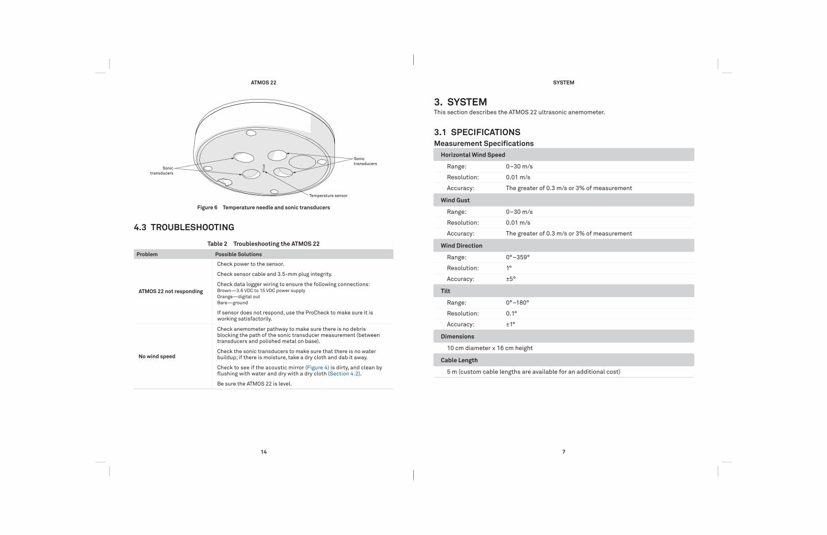
Temperature sensor
Sonic
transducersSonic
transducers
Figure 6 Temperature needle and sonic transducers
4.3 TROUBLESHOOTING
Table 2 Troubleshooting the ATMOS 22
Problem Possible Solutions
ATMOS 22 not responding
Check power to the sensor.
Check sensor cable and 3.5-mm plug integrity.
Check data logger wiring to ensure the following connections:Brown—3.6 VDC to 15 VDC power supply
Orange—digital out
Bare—ground
If sensor does not respond, use the ProCheck to make sure it is working satisfactorily.
No wind speed
Check anemometer pathway to make sure there is no debris blocking the path of the sonic transducer measurement (between transducers and polished metal on base).
Check the sonic transducers to make sure that there is no water buildup; if there is moisture, take a dry cloth and dab it away.
Check to see if the acoustic mirror (Figure 4) is dirty, and clean by fl ushing with water and dry with a dry cloth (Section 4.2).
Be sure the ATMOS 22 is level.
7
SYSTEM
3. SYSTEMThis section describes the ATMOS 22 ultrasonic anemometer.
3.1 SPECIFICATIONS
Measurement Specifi cations
Horizontal Wind Speed
Range: 0 –30 m/s
Resolution: 0.01 m/s
Accuracy: The greater of 0.3 m/s or 3% of measurement
Wind Gust
Range: 0 –30 m/s
Resolution: 0.01 m/s
Accuracy: The greater of 0.3 m/s or 3% of measurement
Wind Direction
Range: 0° –359°
Resolution: 1°
Accuracy: ±5°
Tilt
Range: 0° –180°
Resolution: 0.1°
Accuracy: ±1°
Dimensions
10 cm diameter × 16 cm height
Cable Length
5 m (custom cable lengths are available for an additional cost)

8
ATMOS 22
Electrical and Timing Characteristics
Supply Voltage (VCC) to GND
Minimum 3.6 VDC continuous
Typical
Maximum 15.0 VDC continuous
Digital Input Voltage (logic high)
Minimum 2.8 V
Typical 3.0 V
Maximum 15.0 V
Digital Input Voltage (logic low)
Minimum –0.3 V
Typical 0.0 V
Maximum 0.8 V
Power Line Slew Rate
Minimum 1.0 V/ms
Typical
Maximum
Current Drain (during measurement)
Minimum 0.050 mA
Typical 0.125 mA
Maximum 0.500 mA
Current Drain (while asleep)
Minimum 0.050 mA
Typical 0.125 mA
Maximum 0.150 mA
Operating Temperature Range
Minimum –40 °C
Typical
Maximum 50 °C
13
SERVICE
4. SERVICEThis section contains calibration frequencies, cleaning and maintenance, troubleshooting
guidelines, and contact information..
4.1 CALIBRATIONThe relationship between wind speed and phase is determined by geometry and the laws of
physics. Since the geometry is tightly controlled in manufacture, no individual anemometer
calibration is needed. The phase of each ATMOS 22 anemometer is initially set to zero in a
zero wind speed condition. Extensive wind tunnel and field testing has shown this to result
in accurate wind speed measurements. A subsample of anemometers is checked monthly
for accuracy as part of routine QA/QC (quality assurance) procedures. Routine recalibration
of the ATMOS 22 is not necessary.
4.2 CLEANING AND MAINTENANCEBelow are instructions to clean and maintain the ATMOS 22. Cleaning and maintenance
should be performed as needed.
1. Make sure nothing is obscuring the temperature sensor or the sonic transducers shown in
Figure 6 (cobwebs, leaves, wasp nests, etc.).
2. Check the following areas to make sure they are clear of miscellaneous environmental,
animal (specifi cally bird droppings), insect debris, or spider webs:
a. Anemometer opening
b. Sintered glass reflection plate
3. Clean the ATMOS 22
a. Scrub with light to medium pressure using a warm, damp cloth.
b. Completely dry the instrument by removing excess water using a dry cloth.
c. Clean around posts and between crevices using a dry brush.
d. Be sure the sensor is level after cleaning.
CAUTIONS
• DO NOT immerse the sensor in water.
• DO NOT touch the temperature sensor needle (Figure 6).
• Avoid more than light pressure on the sonic transducers (Figure 6).
NOTE: Do not allow water to enter the ultrasonic sensors (Figure 6). Water may corrode the metal parts inside the
sensors and ruin them. Do not touch the temperature sensor when cleaning because it is very delicate and can be
damaged if pushed into the ATMOS 22 body.

12
ATMOS 22
Equation 7S u 2= + v2
Where the overbar indicates an average of the values sampled every 10 s, wind direction is
computed with Equation 8.
Equation 8 /tan v u1θ = - ^ h
The wind measurement requires 42 ms to complete. An additional 60 ms are required for the
computations to determine phase differences. The anemometer samples every 10 s (or more
often if requested through more frequent SDI-12 commands). The gust speed reported is the
highest instantaneous wind speed measured during the selected averaging interval (must be
>20 s or gusts will equal speed). Wind speeds above 30 m/s are not measured reliably with
the phase shift method, so wind speeds measured above 30 m/s will be reported as 30 m/s.
NOTE: Cup anemometers average over a much longer interval than 42 ms, so the gusts measured with a sonic
anemometer will have a larger peak-to-mean ratio than a cup anemometer.
3.6 LIMITATIONSThe ATMOS 22 is engineered to be a robust device with minimal downtime. However, it does
have limitations that will affect its measurements under some conditions.
3.6.1 SNOW AND ICE ACCUMULATIONAccumulation of snow, ice, or frost can compromise the wind measurements if
accumulation occurs in the anemometer acoustic pathway or on the acoustic mirror
(see Section 4.2).
3.6.2 HEAVY RAIN AND STRONG WINDDuring strong storm events, water can splash off of the horizontal bottom plate of the
anemometer envelope and interrupt the signal passing between the sonic transducers. The
spikes on the bottom plate help dissipate the energy of rainwater to minimize splashing
and reduce the likelihood that the wind measurements are interrupted. Additionally, porous
polyethylene membranes protect the ultrasonic transducers from direct splashing and the
sintered (porous) glass construction draws water from the upper surface of the plate to keep a
constant sound path length. Despite these features, heavy rain and strong wind can still cause
water to reach the membranes and also cause temporary water buildup on the sintered glass.
The hydrophobic nature of the transducer protective membranes and the quick-draining ability
of the sintered glass should limit wind measurement interruptions to heavy rain events and
should bring wind measurement back online soon after extreme conditions abate.
9
SYSTEM
Power Up Time (SDI Ready)—aRx! Commands
Minimum
Typical 10 s
Maximum
Power Up Time (SDI Ready)—Other Commands
Minimum
Typical 800 ms
Maximum
Measurement Duration
Minimum
Typical 110 ms
Maximum 3,000 ms
Compliance
Manufactured under ISO 9001:2015
EM ISO/IEC 17050:2010 (CE Mark)
3.2 ANEMOMETERThe open space in the center of the anemometer is where the ATMOS 22 measures wind
speed. Ultrasonic signals emitted from transducers at right angles to each other bounce
off the porous sintered glass plate (Figure 4) and back up to the opposite sensor. The speed
of sound is affected by the wind, and the wind speed is calculated by measuring differences
in the time it takes for sound to travel back and forth between sensors (Section 3.5).
Splash
guard
Sintered
glass plate
Figure 4 Anemometer

10
ATMOS 22
3.3 TEMPERATURE SENSORThe ATMOS 22 temperature measurement (Figure 5) is made in the small stainless steel
needle containing a tiny temperature sensor (thermistor) that extends from the middle of
the four ultrasonic transducers in the center of the anemometer. The speed of sound is
temperature dependent, so the ATMOS 22 temperature measurement is important for the
wind speed and direction calculations. The ATMOS 22 temperature measurement should
not be used as an accurate measurement of air temperature. Testing has shown errors of as
much as 2 °C between the ATMOS 22 temperature sensor and the true air temperature under
sunny conditions.
NOTE: Temperature data will not be collected by legacy Em50 series data loggers.
Temperature sensor
Figure 5 Temperature sensor
3.4 TILT SENSORThe ATMOS 22 is also equipped with a tilt sensor similar to those found in smartphones.
The primary use of the tilt sensor data will be to ensure the ATMOS 22 remains level
at all times. Regularly check X and Y tilt data to ensure the ATMOS 22 is level; if it has
tilted, return to the site and level again. Although this sensor may also be used to level
the instrument during installation, it is much easier to use the small bubble level on the
bottom of the anemometer plate.
NOTE: Tilt data will not be collected by legacy Em50 series data loggers.
11
SYSTEM
3.5 WIND SPEED AND DIRECTION THEORYThe theory behind the anemometer comes from Campbell and Unsworth (1979). The speed
c (m/s) of sound in still air depends on air temperature T (K), vapor pressure e (kPa), and
atmospheric pressure, p (kPa), as shown in Equation 1.
Equation 1. T.
c pe
20 067 10 32
= +b l
For a given sound path length, d (m), the number of wavelengths, n, in still air is
determined with Equation 2.
Equation 2 n cvd=
Here v is the frequency of the sound (Hz). When the air is moving, the speed of sound is the
sum of the wind speed and the speed of sound in still air. The anemometer transmits a sound
pulse in a forward direction, then a similar pulse in the reverse direction. The difference in n
between the two points is computed. If the vector magnitude of the wind in the direction of
the sound is u (m/s), then
Equation 3 n n c uvdD- = ++
Equation 4 n n c uvdD- = --
for sound traveling with and against the wind. Subtracting the result of Equation 3 from the
results of Equation 4 creates Equation 5.
Equation 5n n nc u
vdu22 2D D D= + =-- +
Even at the maximum wind speeds for the anemometer, u2 is only about 1% of c2, so the
equation can be simplified as shown in Equation 6.
Equation 6 x vdc
n2
2
, D
This is the basic equation for the anemometer. Delta (Δ) n is proportional to the phase
difference between the forward and reverse sound pulses. The sound comes from a
40 kHz ultrasonic transducer in the head of the anemometer. A sound pulse is transmitted
diagonally across the anemometer, bouncing off a sintered glass disk in the center. The
sound pulse is then received by another transducer in the anemometer head that is
opposite the first. Once the sound pulse is received, the receiver becomes the transmitter
and the process is repeated. Two more sensors, mounted at 90 degrees from the first
two, give the other horizontal component of the wind. The sound travels a total distance
of about 72 mm from transmitter to receiver, but d in the equations is just the horizontal
distance, which is 40 mm.
If u is the magnitude of the wind vector in the east–west direction (east +) and v is the magnitude
in the north–south direction (north +), then wind speed is computed with Equation 7.