Embed Size (px)
Citation preview


TABLE OF CONTENTS
1.0 Introduction and Summary .......................................................................................... L-1
2.0 General Well Construction Information ...................................................................... L-2
3.0 Surface Conductor Setting........................................................................................... L-2
4.0 Pilot Hole ....................................................................................................................... L-3
5.0 Geophysical Logs ......................................................................................................... L-3
6.0 Surface and Intermediate (Long String) Well Casing ................................................ L-4
7.0 Cementing ..................................................................................................................... L-4
8.0 Installation of Shutter Screen ...................................................................................... L-6
9.0 Installation of Gravel Pack ........................................................................................... L-6
10.0 Completion .................................................................................................................... L-7
11.0 Airlift Development ....................................................................................................... L-8
12.0 Plumbness and Alignment........................................................................................... L-8
13.0 Well Completion Tests ................................................................................................. L-8
14.0 Wellhead ........................................................................................................................ L-9
15.0 References .................................................................................................................... L-9
L-i

TABLE OF CONTENTS
Appendices
Appendix A Well Construction Detail
Appendix B Material and Equipment Specifications
Appendix C Geophysical Logging Program
Appendix D Gyrocompass Alignment Survey Specifications Appendix E Water and Core Sampling
Appendix F Mechanical Integrity Test
L-ii

Lis t o f Acronyms
~ approximately
API American Petroleum Institute ASME American Society of Mechanical Engineers
ASTM American Society for Testing and Materials
AWS American Welding Society AWWA American Water Works Association
bgs below ground surface
Director Director, UIC Program, California DV differential valve
ECGS El Centro Generating Station
F Fahrenheit gpm gallons per minute
IW injection well KI potassium iodide
KOH potassium hydroxide
mg/L milligrams per liter
MIT mechanical integrity testing
ml milliliter(s) MnSO42H2O manganous sulfate monohydrate
N2 nitrogen
OD outside diameter psi pounds per square inch
SP spontaneous potential SWC sidewall core
TD total depth TDS total dissolved solids UIC Underground Injection Control USEPA United States Environmental Protection Agency
L-iii

ATTACHMENT L Construction Procedures
1.0 INTRODUCTION AND SUMMARY The El Centro Generating Station (ECGS) proposes the installation of three Class I, nonhazardous deep injection wells (IWs) at the locations shown in Attachment B, Maps of Well/Area of Review, Figure B5, Site Plan and Utility Interface, Sheet 1. The proposed injection wells will be drilled to a depth of between 2,740 and 3,660 feet below ground surface (bgs) and constructed in two phases. One well will be completed and tested prior to drilling of the second well. The third well will not be drilled initially, but will serve as a backup if either of the other two wells become inoperable.
Overview – Injection Well Construction Maximum use will be made of current technology and expertise. Contractor selection will be made with regard to prior relevant experience, commercial terms, quality, and safety procedures. Provisional well construction information is provided in a general form in this section. Final well construction may vary depending on geologic conditions encountered at the ECGS site. Three activities, to be performed synchronously with the construction of the well, are:
1. Cementation 2. Geophysical well logging
3. The collection of soil and water samples
Components of the various construction materials and equipment will be assembled, completed, tested, and commissioned to the maximum extent possible. Exact setting depths of all casings or tubing will be determined from field data, based on all available information. The disposal of drilling fluids or cuttings and the disposal of formation water or waste during testing will be done in a sound environmental manner that avoids violation of surface and groundwater quality standards. The ECGS will supervise the collection and removal of material that has the potential to impact the environment. This may include drilling mud and/or drill cuttings, placed in Baker Tanks or other appropriate containers, for removal from the ECGS property to a California state-licensed disposal facility.
Drilling pads will be designed for each injection well to collect spillage of potential contaminants and to support the heaviest load that will be encountered during drilling. If the formation pressure of any confined zone is excessive, flow control will be used to prevent uncontrolled release of formation or drilling fluids at land surface. Details of the provisional design are provided in Appendix A, Well Construction Detail. The material specifications are listed in Appendix B, Material and Equipment Specifications, and the geophysical logging appears in Appendix C, Geophysical Logging Program. Details for performing well alignment logging are shown in Attachment M, Construction Details, Figure M1, Proposed Injection Well Schematic. The methods to be used for the collection of water and soil samples are described in Appendix E, Water and Core Sampling. A provisional description of the mechanical integrity test method is included in Appendix F, Mechanical Integrity Test.
L-1
ATTACHMENT L Construction Procedures
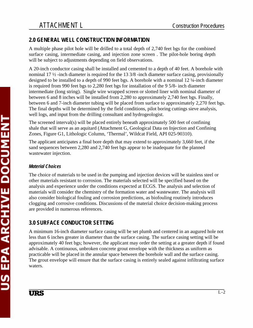
2.0 GENERAL WELL CONSTRUCTION INFORMATION A multiple phase pilot hole will be drilled to a total depth of 2,740 feet bgs for the combined surface casing, intermediate casing, and injection zone screen . The pilot-hole boring depth will be subject to adjustments depending on field observations.
A 20-inch conductor casing shall be installed and cemented to a depth of 40 feet. A borehole with nominal 17 ½ -inch diameter is required for the 13 3/8 -inch diameter surface casing, provisionally designed to be installed to a depth of 990 feet bgs. A borehole with a nominal 12 ¼-inch diameter is required from 990 feet bgs to 2,280 feet bgs for installation of the 9 5/8- inch diameter intermediate (long string). Single wire wrapped screen or slotted liner with nominal diameter of between 6 and 8 inches will be installed from 2,280 to approximately 2,740 feet bgs. Finally, between 6 and 7-inch diameter tubing will be placed from surface to approximately 2,270 feet bgs. The final depths will be determined by the field conditions, pilot boring cuttings sieve analysis, well logs, and input from the drilling consultant and hydrogeologist. The screened interval(s) will be placed entirely beneath approximately 500 feet of confining shale that will serve as an aquitard (Attachment G, Geological Data on Injection and Confining Zones, Figure G1, Lithologic Column, ‘Thermal’, Wildcat Field, API 025-90310). The applicant anticipates a final bore depth that may extend to approximately 3,660 feet, if the sand sequences between 2,280 and 2,740 feet bgs appear to be inadequate for the planned wastewater injection.
Material Choices The choice of materials to be used in the pumping and injection devices will be stainless steel or other materials resistant to corrosion. The materials selected will be specified based on the analysis and experience under the conditions expected at ECGS. The analysis and selection of materials will consider the chemistry of the formation water and wastewater. The analysis will also consider biological fouling and corrosion predictions, as biofouling routinely introduces clogging and corrosive conditions. Discussions of the material choice decision-making process are provided in numerous references.
3.0 SURFACE CONDUCTOR SETTING A minimum 16-inch diameter surface casing will be set plumb and centered in an augured hole not less than 6 inches greater in diameter than the surface casing. The surface casing setting will be approximately 40 feet bgs; however, the applicant may order the setting at a greater depth if found advisable. A continuous, unbroken concrete grout envelope with the thickness as uniform as practicable will be placed in the annular space between the borehole wall and the surface casing. The grout envelope will ensure that the surface casing is entirely sealed against infiltrating surface waters.
L-2

ATTACHMENT L Construction Procedures
4.0 PILOT HOLE Well drilling will be by the rotary process, with bentonite, clay, mud, or other additives appropriate for the return of the drill cuttings.
After emplacement of the surface conductor and surface casing, the pilot hole for the well will be drilled to a nominal 12 ¼-inches or less in diameter to approximately total depth expected to be between 2,740 and 3,660 feet bgs feet deep. The hydrogeologist will provide personnel to collect representative drill cuttings from a sample catcher or splitter at a minimum of every 20 feet of depth and at every change of formation throughout the well installation program. The hydrogeologist will determine the conductivity of the groundwater in the depth interval 200 to 1,200 feet bgs, at intervals that will provide data to locate the depth at which the total dissolved solids (TDS) exceeds 10,000 milligrams per liter (mg/L). The conductivity of the groundwater will be tested after air-flushing the drilling mud from the pilot hole at depth intervals of 20 feet. The Contractor will maintain logs that accurately indicate depth, type, and composition of formation and drilling rate. The drill rig will be equipped with a continuous drilling recorder (Geolograph or equivalent) with a minimum of two pens to record penetration rate and hook load. The drilling logs will be annotated regularly with the weight applied to the drill bit as noted on the indicator, rotary revolutions per minute, bit changes, and comments on rig action. The logs from the drilling time recorder will be turned over to the hydrogeologist at the completion of the drilling.
Deviation Checks During the drilling, the Contractor will check for deviation of the pilot hole, using a method considered appropriate by industry. A deviation survey will be placed in the pilot hole at least every 90 feet (every three joints). The maximum deviation at each measurement will not exceed 1 degree deviation from vertical. A directional survey will also be performed after any hole reaming and prior to the installation of the casing. The Contractor will note the time and angular deviation on the drilling time recorder chart when deviation surveys are conducted and will supply the hydrogeologist with a copy of the alignment information at the completion of each phase of drilling.
With the approval of the Underground Injection Control (UIC) Program Director, the ECGS may request a modification of the provisional well construction design described in this application. The ECGS will submit proof to the UIC Program Director to show that the modification will not adversely affect the successful construction and operation of the injection well(s).
5.0 GEOPHYSICAL LOGS The work required to drill and construct the wells under these specifications also includes work as outlined in State Code § 146.12 for Class I, Deep Injection Wells or as modified by the Director, UIC Program, California (Director). Materials used in construction will be in accordance with American Water Works Association (AWWA), American Petroleum Institute
L-3

ATTACHMENT L C o n s t r u c t i o n P r o c e d u r e s
(API), and American Society for Testing and Materials (ASTM) specifications, unless approved by the Director. Open-hole logs of the pilot hole will be placed before casing is installed. The downhole logs will include: spontaneous potential; resistivity; natural gamma-ray; and caliper. Before conductor and long-string casing is installed, compensated density and/or neutron porosity log, and dipmeter/fracture finder logs will be placed. After casing installation and cementing, a cement bond/variable density log and a temperature log will be placed on all casing strings. In addition, after cementing, a casing inspection log will be placed and an inclination survey will be performed on the conductor and long-string casing.
The well logs and tests will be interpreted by the service company that processed the logs or conducted the test, or by other qualified persons.
Drilling for Surface Casing The hole will be drilled to at least 17 ½ inches to a depth of approximately 990 feet bgs. The hydrogeologist and logging consultant will determine the depth of drilling for the installation of the surface casing of the well after examining geologic and logging data obtained during drilling.
6.0 SURFACE AND INTERMEDIATE (LONG STRING) WELL CASING The UIC Program Director’s approval will be obtained prior to the installation of the ‘long-string’ injection casing and the ‘surface’ casing which extends to the base of the underground source of drinking water. Well casing and screen will be selected according to manufactured specifications such that the tensile, column, and collapse strengths are sufficient to withstand column loads during installation and borehole pressures anticipated for the proposed wells. The welding sequence to be followed will meet the American Welding Society (AWS) specifications. Welders shall be certified and qualified in accordance with the latest revision of the American Society of Mechanical Engineers (ASME) Boiler Construction Code, Section titled “Welding Procedures,” or AWS Standard Qualification Procedure.
The preliminary design is for the installation of approximately 990 feet of 13 3/8-inch diameter K55 conductor casing, followed by approximately 2,280 feet of 9 5/8-inch diameter seamless L80 casing. Approximately 460 feet of single wire wrapped screen or slotted liner will be installed between 2,280 and 2,740 feet bgs.
7.0 CEMENTING The wells will be constructed with two concentric grout-sealed annuli as shown in Attachment M, Construction Details, Figure M1, Proposed Injection Well Schematic, in accordance with State Code No. 146.12.
The cementing contractor will provide a means for centralizing the casing to provide sufficient annular space around the outer perimeter of the casing for an adequate thickness of cement.
L-4

ATTACHMENT L C o n s t r u c t i o n P r o c e d u r e s
The provisional nominal overdrill for the long-string casing that will determine the cement thickness between the casing and formation, and the diameter of the annulus surrounding the final string of casing are shown in Attachment M, Figure M1. The UIC Program Director may request the modification of these provisional dimensions, or request that the ECGS show that the well design will not adversely affect the successful construction and future operation of the wells.
Methods of Cementing The pump-and-plug method (or other method approved by the UIC Program executive director) must be used to cement the injection well casings. This method uses rubber wiper plugs to separate mud, cement, and displacement fluid while being pumped down the casing. A “bottom plug” is pumped down ahead of the cement and is caught on a restriction designed for that purpose in a device called the “float collar” which is positioned near the bottom of the casing.
Classes of Cement and Types of Additives The API has established eight classes of cement based upon suitability for use at various depths and temperatures (Lehr 1986). The Contractor will design the appropriate cement mixtures. A number of special cements, including pozzolan-lime, sulfate-resistant, latex, and epoxy-resin cements, for which the API standards have not been established, have applications in disposal wells. These include accelerators, retarders, light-weight additives, heavy-weight additives, loss-circulation control additives, water-loss control additives, and friction reducers.
Volumes of Cement The cement pumped will be with volume equivalent to at least 120 percent of the volume calculated necessary to fill the annular space between the hole and casing and between casing strings to the surface of the ground. A caliper tool with two or more arms will be used to measure the hole diameter. With regard to any interval of the drilled hole greater than or equal to the maximum readable diameter of the caliper tool, the minimum amount of cement for that interval will be a volume calculated to be equivalent to or greater than 150 percent of the space between the casing and the maximum measurable diameter of the caliper. If lost circulation zones or other subsurface conditions are anticipated and/or encountered, which could result in less than 100 percent filling of the annular space between the casing and the borehole or between the casings, the Contractor will implement a contingency plan approved by the hydrogeologist. The Contractor will incorporate additional measures to optimize the quality of the cementing, including the installation with “guide shoe” and multiple cement stage tools or differential valve (DV) tools in a casing string. These tools allow the casing to be completely cemented in stages. In many situations, use of such tools may be advisable to prevent downhole formations from being subjected to a single-stage cement slurry hydrostatic pressure sufficient to cause formation fracturing in the wellbore. The stage tool may also be used to place different types of cement outside the same casing. In addition, “centralizers” and “scratchers” may be installed on the outside of the casing wall. “Parasite air strings” may also be affixed to the exterior of the surface casing.
L-5

ATTACHMENT L C o n s t r u c t i o n P r o c e d u r e s
The Contractor will consider reducing the drilling mud's 10-minute gel strength and casing wiper plugs ahead of and behind the cement slurry to enable a more efficient sweeping of mud from the annulus outside the casing to minimize mud contamination of the cement. The cement work will meet the United States Environmental Protection Agency (USEPA) performance standard State Code No. 146.8.
8.0 INSTALLATION OF SCREENED COMPLETION The dimensions and preliminary depth of installation of the single wire wrapped screen or slotted liner sections across the proposed injection zones are shown in Attachment M, Figure M1. Centralizers will not be welded to any part of the screen material. The casing string will be supported by casing clamps or hangers welded to both the casing and surface casing prior to releasing tension. All of the casing and screen sections will be joined by continuous welds. The welding work will meet AWS specifications. The fully assembled casing/screen will be suspended just off the bottom of the hole to ensure that it is installed plumb.
9.0 INSTALLATION OF GRAVEL PACK (OPTIONAL) Clean gravel will be placed in the annular space between the screen and borehole wall. The gravel will be composed of sound, durable, highly spherical, well-rounded siliceous particles containing no silt, clay, organic matter, or deleterious materials. The selection of the grade of gravel and appropriate shutter screen will be determined by the hydrogeologist on completion of soil sample sieve analyses. A permanent 2½-inch diameter gravel feed tube will be installed to approximately 10 feet above the top of the screen. The casing assembly will be installed in accordance with the specifications as noted in (Appendix A). Centering guides (centralizers) will be used to ensure that the casing is centered in the hole. Centralizers will be installed at 60-foot spacings.
During gravel placement, a continuous stream of water will be airlifted from the well at a rate of approximately 300 gallons per minute (gpm) to remove suspended sediments. Clean water will be added to the well though the gravel feed tube and to the inside of the surface casing, such that water level in the annulus is not allowed to fall below the bottom of the surface casing during placement of gravel pack and cement seal. The method of gravel placement will be by hydraulic feed through the temporary tremie pipe initially placed at the bottom of the screened interval in the annular space between the open borehole and the screen. To prevent bridging of the gravel pack, no more than 40 feet of tremie pipe will be pulled back at a time during gravel placement. An accurate log of the amount of gravel tremied into the borehole over each 40-foot length of screen will be maintained during installation. The gravel placement will proceed until the height of the gravel pack is approximately 10 feet above the bottom of the permanent gravel feed tube (20 feet above the top of the screen). The Contractor will then place 10 feet of clean, fine silica sand in the well annulus by hydraulic feed through the temporary tremie.
L-6
ATTACHMENT L C o n s t r u c t i o n P r o c e d u r e s
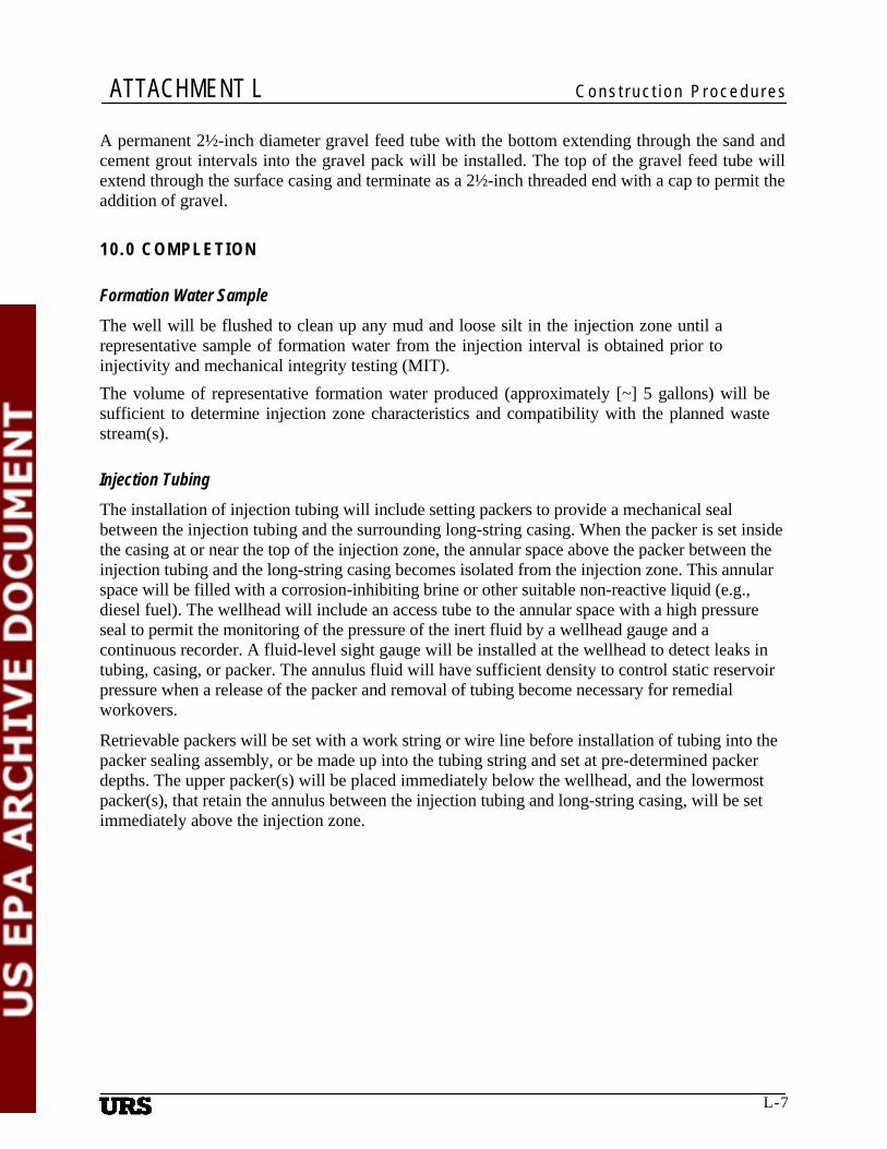
A permanent 2½-inch diameter gravel feed tube with the bottom extending through the sand and cement grout intervals into the gravel pack will be installed. The top of the gravel feed tube will extend through the surface casing and terminate as a 2½-inch threaded end with a cap to permit the addition of gravel.
1 0 . 0 C O M PL ET I O N
Formation Water Sample The well will be flushed to clean up any mud and loose silt in the injection zone until a representative sample of formation water from the injection interval is obtained prior to injectivity and mechanical integrity testing (MIT). The volume of representative formation water produced (approximately [~] 5 gallons) will be sufficient to determine injection zone characteristics and compatibility with the planned waste stream(s).
Injection Tubing The installation of injection tubing will include setting packers to provide a mechanical seal between the injection tubing and the surrounding long-string casing. When the packer is set inside the casing at or near the top of the injection zone, the annular space above the packer between the injection tubing and the long-string casing becomes isolated from the injection zone. This annular space will be filled with a corrosion-inhibiting brine or other suitable non-reactive liquid (e.g., diesel fuel). The wellhead will include an access tube to the annular space with a high pressure seal to permit the monitoring of the pressure of the inert fluid by a wellhead gauge and a continuous recorder. A fluid-level sight gauge will be installed at the wellhead to detect leaks in tubing, casing, or packer. The annulus fluid will have sufficient density to control static reservoir pressure when a release of the packer and removal of tubing become necessary for remedial workovers.
Retrievable packers will be set with a work string or wire line before installation of tubing into the packer sealing assembly, or be made up into the tubing string and set at pre-determined packer depths. The upper packer(s) will be placed immediately below the wellhead, and the lowermost packer(s), that retain the annulus between the injection tubing and long-string casing, will be set immediately above the injection zone.
L-7
ATTACHMENT L Construction Procedures
11.0 AIRLIFT DEVELOPMENT Airlift development of the well will commence a minimum of 12 and no more than 24 hours after completion of grout placement in the well annulus. Airlift development will begin at the bottom of the screen and proceed opposite the entire screen section. Airlift development will be achieved using a swab tool that allows airlift pumping to be conducted through a perforated section of drill pipe between two tight-fitting surge blocks located on the end of the development pipe string.
Airlift development will be conducted by vigorous surging (rawhiding) while producing a continuous flow of formation water at approximately 300 gpm through the long-string casing. Swabbing at a rate of 30 to 40 strokes per hour will be achieved for the airlift development. As the gravel pack settles during development, more gravel will be added to maintain the top of gravel above the bottom of the gravel feed tube at as minimal a level as practicable to avoid bridging. Airlift development will continue until there is no further settling of the gravel and all sand and mud has been washed from the well as determined by the hydrogeologist. The Contractor will maintain a flow of clear potable water through the gravel feed tube during well development activities to avoid bridging of the gravel. Upon completion of airlift development, the Contractor will pump the well to remove all rock, sand, mud, and foreign material. Airlift pumping will again be used during this phase of the well installation and will continue until the water is clean and free of sand and silt.
12.0 PLUMBNESS AND ALIGNMENT The well will be constructed in such vertical alignment that a line drawn from the center of the well casing at the ground surface will not deviate from the vertical by more than 1 degree in 90 feet of length unless otherwise authorized by the hydrogeologist. To verify that the well is sufficiently straight and plumb, the Contractor will either place a gyrocompass alignment survey as noted in the (Appendix D), or pass a full length stabilizer down the length of the pilot hole.
13.0 WELL COMPLETION TESTS On completion of construction with well, the following tests will be performed:
• A cement evaluation survey • Temperature survey • Pressure test of the final casing to at least 1.5 times the expected injection pressure or 350
pounds per square inch (psi), whichever is greater, for 30 minutes, with a change in pressure of no more than 5 percent from the initial test pressure
• Video television survey – from the top to bottom of the well for baseline monitoring purposes
• Injection tests • Caliper survey • Radioactive tracer survey
L-8

ATTACHMENT L Construction Procedures
14.0 WELLHEAD The wellhead will be completed, ready for installation of surface monitoring equipment, including pressure, flow, and temperature gauges. The wellhead slab will be at least 6-foot by 6-foot, with the edges aligned east/west and north/south, finished 6 inches above finished grade. The 6-foot by 6-foot slab will extend to 3 feet below finished grade, and the bottom will slope downward toward the top of the surface casing seal grout so that it forms a continuous seal with the grout. The central pedestal will be 3feet by 3-feet square, finished level and flush with the top of the well casing 2 feet above the top of the wellhead slab (2.5 feet above finished grade). The wellhead slab and central pedestal will be poured as one unit using 3,000-psi concrete. The gravel tube will project 6 inches above the wellhead slab, at an angle of 30 degrees from vertical through the well slab, and have a screw-on cap marked with a "G." Two 2-inch galvanized vent pipes will penetrate the well casing and project at a 45-degree angle from vertical, positioned so that they project from the side of the pedestal, or the top of the wellhead slab. The two vents will each have a threaded coupler so that the extensions can be removed below the level of the top of the central pedestal. The vent pipes will be seal-welded to the casing so that no portion of the vent pipes protrudes into the casing interior. One of the vent pipes will terminate in an elbow with its opening downward, and screened to prevent entry of insects. The opening will be at least 18 inches above finished grade. The other vent pipe will be terminated with a screw-on cap at least 18 inches above finished grade.
15.0 REFERENCES Lehr, J.H. 1986. Underground Injection – A Positive Advocate, in Proceedings of the
International Symposium on Subsurface Injection of liquid Wastes: National Water Well Association, Dublin, Ohio, p. 51-56.
L-9

Appendices

Appendix A Wel l Construct ion Deta i l
Alternative Drilling and Casing Program
• Drill 26-inch hole to ~40 feet bgs for conductor casing.
• Install 20-inch 94# J-55 casing to ~40 feet bgs.
• Drill 17 ½ inches from 0 to an estimated depth of 990 feet bgs using water-base drilling mud. The final depth to be determined by groundwater TDS value.
• Place geophysical logs, collect water samples, and obtain sidewall cores (SWCs).
• Install 13 5/8-inch, K-55 grade surface casing from surface to 990 feet. • Inject cement between formation and 13 5/8 -inch surface casing.
• Place logging tools to demonstrate that the ‘cement is continuous’ behind the well bore. • Drill 12 ¼ -inch pilot hole from 0 to 2,280 feet. • Place geophysical logs, collect water samples, and obtain sidewall cores (SWCs) on open hole. • Install L-80 grade 9-5/8-inch intermediate (long-string) casing from 0 to 2,280 feet bgs. • Inject cement behind intermediate (long-string) casing. • Place logging tools to demonstrate continuity of cement behind casing.
• Drill 8 ¾-inch pilot hole from 2,280 to 2,740, the estimated final depth of hole.
• Circulate and condition hole, and pull out of hole. • Install 7 7/8 -inch stainless steel single wire wrapped screen with L-80 grade base pipe or 7
inch L-80 grade slotted liner from 2,280 to 2,740 feet bgs.
• Install 7-inch L-80 grade hang-down tubing from approximately 0 to 2,270 feet bgs
• Install packers between long-string casing and injection tubing for well annulus. • Complete topside access piping, connect flow and pressure gauges, and erect housing for
electronic monitoring equipment. • Fill annulus with water with corrosion retardant, and pressure-test wellhead seals and
equipment.
Attachment L, Appendix A-1

Appendix B Material and Equipment Specifications
•
Grout Specifications • Mix proportions or standard specs • Clay seal specs • Material and form introduced
Casing Specifications • Thickness
• Material
• Certifications • Condition delivered • Surface casing specs
Screened Completion Specifications
The screened completion will be a minimum 6-inch diameter single wire-wrapped screen made of stainless steel with an L-80 grade base pipe of sufficient collapse strength for the application. Alternately a L-80 grade slotted liner may be used. Maximum slot size will be based on further investigation of the formation within the injection interval. The percentage of open area in the screened interval will be maximized to the extent practical.
Gravel-Pack Specifications The gravel-pack material used will be Colorado silica or equivalent, with respect to grain size distribution, roundness, and composition. The casing/well-screen assembly will be suspended in the borehole, just off the bottom during installation of the gravel pack and seal materials to ensure plumb installation. The gravel-pack material will be introduced into the annular space surrounding the casing/well-screen by use with 3-inch diameter tremie pipe, the end of which will be suspended just above the interval being installed. The tremie pipe will be withdrawn during installation to keep its tip above the installed gravel pack. The gravel-pack material will be introduced as slurry made with water and disinfectant to avoid bridging in the pipe or in the borehole annular space. Circulation will be maintained in the hole to ensure proper gravel-pack development.
Gravel-pack material will be continued 20 feet past the top of any screened interval. When the top of the last gravel-packed interval is reached, the tremie pipe will be set down on top of the gravel-pack material, filled with the same gravel pack material to the surface, and left in the annular space as a gravel tube. It will be capped and labeled “gravel” and terminated on its top end, so as to be accessible for gravel replenishment after completion of the well. The remainder of the annular space will be filled (around the gravel tube) with an appropriate seal material for the conditions present.
Attachment L, Appendix B-1

Appendix BMaterial and Equipment Specifications
Sieve Analysis • Roundness
• Composition • Certifications
Pressure Test Pump Specifications • T o b e d e t e r m i n e d
Injection Well Drilling and Casing, Provisional Data
Casing Material Depth Interval
(ft) Hole Diameter
(in)
Casing Diam.
(in)
Nominal Weight (lb/ft)
Internal Yield
Pressure (psi)*
Total Footage
K-55 0-40 26 20 94.0 2,110 40
K-55 Seamless 0-990 17 ½ 13 3/8 54.5 2,730 990
K-55 or L-80 Seamless 0 to 2,280 12 ¼ 9 5/8 40.0
(47.0) 3,950
(6,870) 2,280
S/S SWWS Screen or Slotted Liner L
80
2,280 to 2,740
8 ¾ 7 5/8 (7) 26.4 (26.0)
6,020 (7,240)
460
L-80 Seamless 0 to 2,270 8 (=ID of long string)
7 26 7,240 2,270
* Halliburton, eRedbook Copyright 2006, http://www.halliburton.com\eRedbook
Attachment L, Appendix B-2

Appendix C Geophysical Logging
Summary Dual induction, spontaneous potential (SP), gamma ray, and neutron-density logs will be placed through the confining and injection zones after the IWs are drilled to total depth (TD). A cement bond log will be placed from the top of the injection zone to surface after each section of casing is cemented in place. Ten sidewall samples will be acquired from the first well to be drilled for laboratory analysis.
A. Open-Hole Logs
The geophysical logs will be placed in the open hole immediately following completion of each section. The following geophysical logs will be placed in the open hole:
1. Natural gamma 2. Spontaneous potential 3. Dual induction 4. Neutron-density 5. Caliper (four-arm) 6. Electromagnetic induction
The geophysical logs will be placed from the bottom of the boreholes to the bottom of conductor casing. A set of backup tools should be on site, or accessible within a reasonable amount of time, to reduce downtime in case of tool failure and to minimize the amount of time that the hole stands open.
B. Logging through conductor/surface casing:
1. Before casing and cementing: dual induction, SP, gamma ray, neutron-density, caliper logs, etc.
2. After casing and cementing: cement bond, temperature, gamma ray, neutron logs, etc.
C. Logging through long-string casing
1. Before casing and cementing: dual induction, SP, gamma ray, neutron-density, caliper logs, etc.
2. Fracture locating logs 3. After casing and cementing: cement bond, temperature, gamma ray, neutron logs, etc. 4. Radioactive tracer, spinner, and video logs.
Attachment L, Appendix C-1

Appendix D Gyrocompass Alignment Survey Specifications
General Information The injection wells will be surveyed with a high-speed gyrocompass and plumb-bob assembly equipped with a multi-shot camera and full-gauge centralizers. Well orientation measurements will be conducted every 20 feet for the entire depth of the hole. A repeat survey of the first 200 feet of each cased well will be conducted to ensure precision of the survey. The precision of the measurements will be ± 2-½ minutes for inclination (drift angle), ± 1 degree for azimuth (drift direction), and ± 1 foot for true vertical depth. The hydrogeologist will be present during the plumbness and alignment surveys.
A written report will be submitted, in triplicate, within 5 days of the survey. The report will contain a drawing of the horizontal projection of the well and the following tabulated survey data:
• Depths of measurements
• Course length • Drift angle • Vertical depth
• True vertical depth • Drift direction
• North/south and east/west coordinate differences
• North/south and east/west rectangular coordinates • Degree of dogleg per 100 feet • Degree of dogleg per 20-foot course length
The data will be supplied in digital format along with any special readers required to view the data unless in Microsoft Word, Excel, or PDF format.
Attachment L, Appendix D-1

Appendix E Water and Core
Water Sampling for Chemical Analysis Sample bottles and directions for taking samples will be obtained from the laboratory. Arrangements will be made to coordinate the collection, transportation, and testing of the samples so as to minimize delay in testing for pH, bacteria, and other constituents where holding times are relatively short. When taking bacteriological samples, the bottles will be sterile and care will be exercised not to contaminate either the bottle or the sample. The sample tap will be allowed to flow smoothly for at least 1 minute before collection with sample. Samples for mineral analysis will be taken in clean bottles with plastic (non-metal) caps.
The temperature will be taken of all water samples to provide a clue as to the average depth of the producing aquifers. The thermometer will have a scale engraved on the glass and the graduations will be such that an estimate will be possible of the reading to the nearest degree Fahrenheit (F).
Samples for dissolved oxygen will have the following equipment and reagents available: • A ¼-inch outside diameter (OD) polyethylene tube that can be connected to the sample tap.
• A special sample bottle with a tapered ground-glass stopper. It should have a capacity of approximately 250 milliliters (mL).
• Three small (35- to 100-mL) bottles equipped with screw-on rubber bulb dispensing pipettes. The pipettes should discharge approximately 0.5 mL when the bulb is squeezed (an ordinary eye dropper is satisfactory).
• The first bottle will contain a 40 percent solution of manganous sulfate monohydrate (MnSO42H2O).
• The second bottle will contain alkaline iodine reagent consisting of 70 grams of potassium hydroxide (KOH) and 150 grams potassium iodide (KI) diluted to 100 mL.
• The third bottle will contain concentrated sulfuric acid. The sample bottle will be filled with water, using the plastic tube immersed almost to the bottom of the special bottle. It will be allowed to overflow to displace 4 to 10 volumes. The eye dropper containing the manganous sulfate will be immersed under the surface of the water and 1 mL (two squirts) of manganese sulfate reagent added. Next, 1 mL of alkaline iodide reagent will be added, with no air bubbles entrapped. The floc of manganese hydroxide will be allowed to settle for 3 or 4 minutes before removing the stopper. One mL of concentrated sulfuric acid will be added, and the stopper inserted and the solution mixed by inverting the bottle. The solution will be transported to the laboratory for oxygen determination.
Attachment L, Appendix E-1

Appendix F Mechanical Integr i ty
A mechanical integrity test, or MIT, is a pressure test performed on every injection well to determine that no significant fluid is leaking through the well casing, tubing, or packer into formations that could be sources of drinking water. The MIT is designed to test the entire system including the tubing, packer, and wellhead. The test is performed by applying pressure to the space between the casing and the tubing for a period of 30 minutes. If a pressure drop is observed that causes the well to fail the test, then the casing, tubing or packer, or wellhead has developed a leak. The leak must be fixed and the test retaken.
MIT Test Procedure 1. Give a 45-day advance notice to USEPA so an inspector can be scheduled. USEPA will
send out a certified letter to the operator with the time and date of the test. The letter will have contacts and phone numbers.
2. Ensure that the packer is properly set in casing at the depth specified in the permit. Fill annular space with fluid. Air should be totally displaced.
3. Check all valves, secure tubing, and ensure that all leaks are repaired.
4. With inspector on location, apply pressure on tubing annular space (usually with nitrogen [N2]). Oxygen should not be used because of safety concerns.
5. Apply a minimum 350-pound pressure on tubing annulus for 30 minutes. The USEPA representative will monitor pressure variations at the time of the test. Pressure changes cannot exceed 5 percent above or below the applied pressure (17.5 pounds per 350 pounds of applied pressure).
Attachment L, Appendix F-1