Embed Size (px)
Citation preview

Introduction 1
Information about the Library 2
Description of Blocks 3
Description of the Excel Add-In
4
Configuration Manual 5
Technical Data 6
Technical Support 7
Energy Management for PCS7
SIMATIC PCS 7 powerrate
Manual
03/2008

Safety guidelines
Safety guidelines This manual contains notices you have to observe in order to ensure your personal safety, as well as to prevent damage to property. The notices referring to your personal safety are highlighted in the manual by a safety alert symbol, notices referring only to property damage have no safety alert symbol. The notices shown below are graded according to the degree of danger.
DANGER indicates that death or severe personal injury will, result if proper precautions are not taken.
WARNING indicates that death or severe personal injury may result if proper precautions are not taken.
CAUTION with a safety alert symbol indicates that minor personal injury can result if proper precautions are not taken.
CAUTION without a safety alert symbol indicates that property damage can result if proper precautions are not taken.
NOTICE indicates that an unintended result or situation can occur if the corresponding information is not taken into account.
If more than one degree of danger is present, the warning notice representing the highest degree of danger will be used. A notice warning of injury to persons with a safety alert symbol may also include a warning relating to property damage.
Qualified personnel The device/system may only be set up and used in conjunction with this documentation. Commissioning and operation of a device/system may only be performed by qualified personnel. Within the context of the safety notes in this documentation, qualified persons are defined as persons who are authorized to commission, ground, and label devices, systems, and circuits in accordance with established safety practices and standards.
Prescribed usage Note the following:
WARNING This device may only be used for the applications described in the catalog or the technical description and only in conjunction with devices or components from other manufacturers which have been approved or recommended by Siemens. Correct, reliable operation of the product requires proper transport, storage, positioning, and assembly as well as careful operation and maintenance.
Trademarks All names identified by ® are registered trademarks of the Siemens AG. The remaining trademarks in this publication may be trademarks whose use by third parties for their own purposes could violate the rights of the owner.
Disclaimer of liability We have reviewed the contents of this publication to ensure consistency with the hardware and software described. Since variance cannot be precluded entirely, we cannot guarantee full consistency. However, the information in this publication is reviewed regularly and any necessary corrections are included in subsequent editions.
Siemens AG Automation and Drives P.O. Box 48 48 90327 NUREMBERG GERMANY
Ⓟ 03/2008
Copyright © Siemens AG 2007. Subject to change without prior notice

Contents SIMATIC PCS 7 powerrate Manual
Siemens AG 3 SIMATIC PCS 7 powerrate Manual V2.0
Contents
SAFETY GUIDELINES ..................................................................................................................2
CONTENTS....................................................................................................................................3
1 INTRODUCTION.............................................................................................................. 7
1.1 General ........................................................................................................................................ 7
1.2 Installing the library ................................................................................................................. 7
2 INFORMATION ABOUT THE LIBRARY......................................................................... 8
2.1 Overview of the blocks............................................................................................................ 8
2.2 Overview of the Excel Add-In ................................................................................................ 8
2.3 General information about OS typicals............................................................................... 9 2.3.1 Faceplates .............................................................................................................................. 9 2.3.2 Icons ...................................................................................................................................... 11
3 DESCRIPTION OF BLOCKS......................................................................................... 12
3.1 PRE_SYNC: Time synchronization .................................................................................... 12 3.1.1 Calling OBs .......................................................................................................................... 12 3.1.2 Called blocks........................................................................................................................ 12 3.1.3 Function ................................................................................................................................ 12 3.1.4 Message behavior ............................................................................................................... 12 3.1.5 Error behavior ...................................................................................................................... 12 3.1.6 Startup characteristics ........................................................................................................ 12 3.1.7 Block parameters ................................................................................................................ 13
3.2 PRE_SUM: Energy acquisition and processing ............................................................. 14 3.2.1 Calling OBs .......................................................................................................................... 14 3.2.2 Called blocks........................................................................................................................ 14 3.2.3 Function ................................................................................................................................ 14 3.2.4 Message behavior ............................................................................................................... 16 3.2.5 Error behavior ...................................................................................................................... 16 3.2.6 Startup characteristics ........................................................................................................ 17 3.2.7 Block parameters ................................................................................................................ 17 3.2.8 Description of icon and faceplate...................................................................................... 19
3.3 PRE_FIFO_DATA: FIFO buffer ............................................................................................ 23 3.3.1 Calling OBs .......................................................................................................................... 23 3.3.2 Called blocks........................................................................................................................ 23 3.3.3 Function ................................................................................................................................ 23 3.3.4 Message behavior ............................................................................................................... 24 3.3.5 Error behavior ...................................................................................................................... 24 3.3.6 Startup characteristics ........................................................................................................ 24

SIMATIC PCS 7 powerrate Manual Contents
4 Siemens AG SIMATIC PCS 7 powerrate V2.0 Manual
3.3.7 Block parameters .................................................................................................................24
3.4 PRE_AR_DATA: Data interface for sending the archive data .....................................25 3.4.1 Calling OBs ...........................................................................................................................25 3.4.2 Called blocks ........................................................................................................................25 3.4.3 Function.................................................................................................................................25 3.4.4 Message behavior................................................................................................................26 3.4.5 Error behavior .......................................................................................................................26 3.4.6 Startup characteristics.........................................................................................................26 3.4.7 Block parameters .................................................................................................................26
3.5 PRE_AR_SND: Archiving measured values .....................................................................27 3.5.1 Calling blocks .......................................................................................................................27 3.5.2 Called blocks ........................................................................................................................27 3.5.3 Function.................................................................................................................................27 3.5.4 Message behavior................................................................................................................27 3.5.5 Error behavior .......................................................................................................................27 3.5.6 Startup characteristics.........................................................................................................27 3.5.7 Block parameters .................................................................................................................28
3.6 PRE_LMGM: Load management..........................................................................................29 3.6.1 Calling blocks .......................................................................................................................29 3.6.2 Called blocks ........................................................................................................................29 3.6.3 Function.................................................................................................................................29 3.6.4 Message behavior................................................................................................................37 3.6.5 Error behavior .......................................................................................................................38 3.6.6 Startup characteristics.........................................................................................................39 3.6.7 Block parameters .................................................................................................................39 3.6.8 Description of icon and faceplate ......................................................................................45
3.7 PRE_AS_SEND: AS-to-AS communication ......................................................................56 3.7.1 Calling blocks .......................................................................................................................56 3.7.2 Called blocks ........................................................................................................................56 3.7.3 Function.................................................................................................................................56 3.7.4 Message behavior................................................................................................................56 3.7.5 Error behavior .......................................................................................................................57 3.7.6 Startup characteristics.........................................................................................................57 3.7.7 Block parameters .................................................................................................................57
3.8 PRE_AS_RECV: AS-to-AS communication ......................................................................59 3.8.1 Calling blocks .......................................................................................................................59 3.8.2 Called blocks ........................................................................................................................59 3.8.3 Function.................................................................................................................................59 3.8.4 Message behavior................................................................................................................59 3.8.5 Error behavior .......................................................................................................................60 3.8.6 Startup characteristics.........................................................................................................60 3.8.7 Block parameters .................................................................................................................60
3.9 PRE_SND_H: AS-4xxH to AS-4xx communication .........................................................62 3.9.1 Calling blocks .......................................................................................................................62 3.9.2 Called blocks ........................................................................................................................62 3.9.3 Function.................................................................................................................................62 3.9.4 Message behavior................................................................................................................63 3.9.5 Error behavior .......................................................................................................................63

Contents SIMATIC PCS 7 powerrate Manual
Siemens AG 5 SIMATIC PCS 7 powerrate Manual V2.0
3.9.6 Startup characteristics ........................................................................................................ 63 3.9.7 Block parameters ................................................................................................................ 64
3.10 PRE_RCV_H: AS-4xxH to AS-4xx communication ........................................................ 66 3.10.1 Calling blocks ....................................................................................................................... 66 3.10.2 Called blocks........................................................................................................................ 66 3.10.3 Function ................................................................................................................................ 66 3.10.4 Message behavior ............................................................................................................... 67 3.10.5 Error behavior ...................................................................................................................... 67 3.10.6 Startup characteristics ........................................................................................................ 67 3.10.7 Block parameters ................................................................................................................ 68
3.11 PRE_BS: Calling the BSEND system function block .................................................... 70 3.11.1 Calling blocks ....................................................................................................................... 70 3.11.2 Called blocks........................................................................................................................ 70 3.11.3 Function ................................................................................................................................ 70
3.12 PRE_BR: Calling the BRCV system function block ....................................................... 70 3.12.1 Calling blocks ....................................................................................................................... 70 3.12.2 Called blocks........................................................................................................................ 70 3.12.3 Function ................................................................................................................................ 70
3.13 PRE_CALC: Calculations...................................................................................................... 71 3.13.1 Calling blocks ....................................................................................................................... 71 3.13.2 Function ................................................................................................................................ 71 3.13.3 Message behavior ............................................................................................................... 71 3.13.4 Error behavior ...................................................................................................................... 71 3.13.5 Startup characteristics ........................................................................................................ 71 3.13.6 Block parameters ................................................................................................................ 72
3.14 PRE_FIFO_IO: Organization of FIFO buffer ..................................................................... 72 3.14.1 Calling blocks ....................................................................................................................... 72 3.14.2 Called blocks........................................................................................................................ 72 3.14.3 Function ................................................................................................................................ 72 3.14.4 Message behavior ............................................................................................................... 72 3.14.5 Error behavior ...................................................................................................................... 72 3.14.6 Startup characteristics ........................................................................................................ 72 3.14.7 Block parameters ................................................................................................................ 73
3.15 UDT_PRE_FIFO ....................................................................................................................... 74 3.15.1 Description ........................................................................................................................... 74 3.15.2 Structure ............................................................................................................................... 74
3.16 UDT_PRE_ITEM....................................................................................................................... 74 3.16.1 Description ........................................................................................................................... 74 3.16.2 Structure ............................................................................................................................... 74
3.17 UDT_PRE_TLG ........................................................................................................................ 75 3.17.1 Description ........................................................................................................................... 75 3.17.2 Structure ............................................................................................................................... 75
4 DESCRIPTION OF THE EXCEL ADD-IN...................................................................... 76
4.1 Cost center report................................................................................................................... 77

SIMATIC PCS 7 powerrate Manual Contents
6 Siemens AG SIMATIC PCS 7 powerrate V2.0 Manual
4.2 Duration curve report .............................................................................................................78
5 CONFIGURATION MANUAL ........................................................................................ 79
5.1 Configuring measuring points for energy/power acquisition .....................................79 5.1.1 Writing the AS program.......................................................................................................79 5.1.2 Connection to WinCC ..........................................................................................................82 5.1.3 Configuring the process value archive .............................................................................84
5.2 Configuring load management ............................................................................................87 5.2.1 Writing the AS program.......................................................................................................87 5.2.2 Connection to WinCC ..........................................................................................................89 5.2.3 Configuring the user archive in WinCC ............................................................................89
5.3 Configuring the Excel Add-In ...............................................................................................91 5.3.1 Connection to WinCC ..........................................................................................................91 5.3.2 Starting the Excel Add-In ....................................................................................................91 5.3.3 Read Taglist: Reading tag names .....................................................................................91 5.3.4 Configuring report data .......................................................................................................91 5.3.5 Reading archive tags...........................................................................................................94
6 TECHNICAL DATA........................................................................................................ 96
7 TECHNICAL SUPPORT ................................................................................................ 98

Introduction SIMATIC PCS 7 powerrate Manual
Siemens AG 7 SIMATIC PCS 7 powerrate Manual V2.0
1 Introduction
1.1 General
The SIMATIC PCS 7 powerrate (pre for short) V2.0 software package can be used in PCS 7 versions V6.1 SP1 and V7.0 SP1 and contains the following components:
- Block library with:
o PRE_SYNC: Time synchronization
o PRE_SUM: PCS 7 block for acquiring and processing energy
o PRE_FIFO_DATA: Contains the FIFO data
o PRE_AR_DATA: Data interface for sending the archive data
o PRE_AR_SND: Archives measured values
o PRE_LMGM: Load management
o PRE_AS_SEND: Send block for AS-to-AS communication
o PRE_AS_RECV: Receive block for AS-to-AS communication
o PRE_SND_H: Send block for AS-4xxH to AS-400 communication
o PRE_RCV_H: Receive block for AS-4xxH to AS-400 communication
o PRE_BS: Calls the BSEND system block
o PRE_BR: Calls the BRCV system block
o PRE_CALC: Calculation block
o PRE_FIFO_IO: Organizes the FIFO buffer
o CFC templates for using the blocks
o User objects and operating blocks for operating and observing energy acquisition data and load management on the OS
- Excel Add-In with the functions:
o Reading the archive data from the WinCC Tag Logging archive to Excel
o Further processing of archive data
o Output of archive data in the form of Excel reports
- Online help in German and English
1.2 Installing the library
To start the installation, please insert the CD in the CD-ROM drive on your PG/PC and launch the "setup.exe" program. All the other information you need will be provided during the installation process. Please also read the information in the readme file.

SIMATIC PCS 7 powerrate Manual Information about the library
8 Siemens AG SIMATIC PCS 7 powerrate V2.0 Manual
2 Information about the library
2.1 Overview of the blocks
The library contains the following blocks:
Name Function Number PRE_SYNC Time synchronization FB1060 PRE_SUM PCS 7 block for acquiring and processing energy FB1061 PRE_FIFO_DATA FIFO buffer FB1062 PRE_AR_DATA Data interface for sending the archive data FB1063 PRE_AR_SND Archives measured values in the WinCC Tag Logging archive FB1064 PRE_LMGM Load management FB1065 PRE_AS_SEND Send block for AS-to-AS communication FB1070 PRE_AS_RECV Receive block for AS-to-AS communication FB1071 PRE_SND_H Send block for AS-4xxH to AS-400 communication FB1072 PRE_RCV_H Receive block for AS-4xxH to AS-400 communication FB1073 PRE_BS Calls the BSEND system function block (is used internally) FB1074 PRE_BR Calls the BRCV system function block (is used internally) FB1075 PRE_CALC Calculation block FC1061 PRE_FIFO_IO Organizes the FIFO buffer FC1062 UDT_PRE_FIFO Data type for check data for organizing the FIFO buffer UDT1060 UDT_PRE_ITEM Data type for measured value UDT1061 UDT_PRE_TLG Data type for telegram element for sending to the WinCC Tag
Logging archive UDT1062
2.2 Overview of the Excel Add-In
The Excel Add-In contains the following files:
Name Function pre_Reporting.xla - Reading the archive data from the WinCC Tag Logging archive to
Excel - Further processing of archive data - Output of archive data in the form of Excel reports
pre_Configuration.xls Configuration file DataReading.xlt Template for data storage and reports

Information about the library SIMATIC PCS 7 powerrate Manual
Siemens AG 9 SIMATIC PCS 7 powerrate Manual V2.0
2.3 General information about OS typicals
2.3.1 Faceplates
Faceplates are configured with the Graphics Designer using the templates and PCS 7-specific standard views (Trend, Batch, and Alarm) provided by the Faceplate Designer. If other user objects are required, they can be added.
The faceplates described are provided as functional and tested examples and can be adapted by the user to reflect his or her own needs.
Icons are provided for the PRE_SUM energy acquisition block and the PRE_LMGM load management block, with a group display including all necessary displays also being provided for each of these two blocks. The PRE_SUM block also has a loop display. The relevant group display is called using the icon.
A description that allows the user to adapt the faceplates (description of interface to energy acquisition block PRE_SUM / load management block PRE_LMGM, description of operating and display functions) is provided along with the faceplates.
Overview The display forms part of the @PG_PRE_SUM_OVERVIEW.PDL/@PL_PRE_SUM_OVERVIEW.PDL and @PG_PRE_LMGM_OVERVIEW.PDL/@PL_PRE_LMGM_OVERVIEW.PDL basic displays.
Group display
Message lock (MSG_LOCK) Message
acknowledgement
Message suppression (QMSG_SUP)

SIMATIC PCS 7 powerrate Manual Information about the library
10 Siemens AG SIMATIC PCS 7 powerrate V2.0 Manual
Trend (@PCS7_TREND.PDL) The "ReturnPath" and "StandardTrend" properties must be parameterized on the icon to incorporate a trend in a faceplate.
• StandardTrend 2 Online values with 5 min time axis
> 2 Archive values with time axis of the value entered (in min)
• ReturnPath .S Structural element name starting with a full stop
: Separator
CO_GREEN Color for trend
Add the structural element name and color to other trends (e.g. .S:CO_GREEN,.V:CO_RED)
*asia Skip the server prefix in the archive tag name
: Separator
*archivname:pre Archive name of pre-archive
Since a dynamic selection is made for the PRE_SUM faceplate as regards whether the online values or archive tags will be accessed, the ReturnPath_Online (for online values) / ReturnPath_Archive (for archive tags) properties must be parameterized here.

Information about the library SIMATIC PCS 7 powerrate Manual
Siemens AG 11 SIMATIC PCS 7 powerrate Manual V2.0
Separate trends can be produced for other display types (e.g. comparison of a trend value over several time domains) with the help of the "Trends online" function. The button from the bottom strip of buttons shown below is used for calling.
2.3.2 Icons
The process display icons are based on the process symbols provided by the Faceplate Designer. The diagrams are schematic diagrams. Template diagrams @PCS7Typicals_PRE.pdl/@Template_PRE.pdl The block icons can be found in the template diagrams @PCS7Typicals_PRE.pdl and @Template_PRE.pdl. To be able to use the "Create / update block icons" function in the Graphics Designer, you have to copy the icons of the @Template_PRE.pdl file into @Template.pdl.
When using the "Create/Update Block Icons" function, PCS 7 accesses the file @PCS7Typicals_PRE.pdl.
When manually copying the icons into a process display, you must use the icons from the @Template_PRE.pdl file. When updating the icons, PCS 7 accesses the @Template.pdl file. Different variants of block icons There may be several variants of block icons for one measuring point. These variants are distinguished by the "type" attribute: The value of this attribute describes the variant. For example, if you look at a variant of the block icon for a measuring point for energy acquisition, you will find the value "@PRE_SUM/2". You use the part of the value displayed after the "/" to control which variant of the block icon is produced. You therefore have to enter this part in the object properties for the block instance. If you do not enter any parameters in the object properties for the block instance, the standard block icon is produced automatically: This is the block icon with the "/1" label for the "type" attribute, e.g. "@PRE_SUM/1". Connection to the measuring point For the different blocks, there is one icon that is linked to the associated measuring point using the "Connect picture block to tag structure" function.
The block icons contain the following visible information:
Equipment identifier (tag name)
Group display (EventState)
Power (CUR_PWR/Unit: CUR_PWR#unit)
Mode (QMAN_AUT)
Energy (work) (CUR_VAL/Unit: CUR_VAL#unit)

SIMATIC PCS 7 powerrate Manual Description of blocks
12 Siemens AG SIMATIC PCS 7 powerrate V2.0 Manual
3 Description of blocks
3.1 PRE_SYNC: Time synchronization
FB1060
3.1.1 Calling OBs The OB alarm in which the block is installed (e.g. OB32). Also in OB100 (see startup characteristics).
3.1.2 Called blocks
The block calls the following blocks:
SFC1 READ_CLK SFC6 RD_SINFO FC1 AD_DT_TM (IEC function from the STEP 7 Standard Library) FC34 SB_DT_DT (IEC function from the STEP 7 Standard Library)
3.1.3 Function The block acts as the clock for time synchronization for the PRE_SUM block for energy acquisition. The SYNC_OUT clock is triggered by an external synchronization signal (EXT_SYNC) or the internal CPU time. If the external synchronization is deactivated (EXT_EN = FALSE), REQ_PER contains the period time for synchronization. During external synchronization (EXT_EN = TRUE) the time stamp for the synchronization pulse (SYNC_TS) is rounded to the next whole time value (e.g. 15-minute value) according to the expected period time of the external synchronization signal (REQ_PER) and of the current CPU time stamp.
3.1.4 Message behavior The block has no message behavior.
3.1.5 Error behavior The QPARAMF error output is set when - Synchronization period REQ_PER or synchronization pulse REQ_T <= 0 - Synchronization period REQ_PER is less than the period of synchronization pulse REQ_T - Synchronization period REQ_PER is greater than one hour - Synchronization period REQ_PER is not a whole second value - Synchronization period REQ_PER is not a divisor of an hour
3.1.6 Startup characteristics The times are restarted during startup.

Description of blocks SIMATIC PCS 7 powerrate Manual
Siemens AG 13 SIMATIC PCS 7 powerrate Manual V2.0
3.1.7 Block parameters Element Data type Type Description OCM CUR_TS DATE_AND_TIME O Current time stamp when block is called EXT_EN BOOL I 1=Release for external synchronization EXT_SYNC BOOL I External synchronization pulse QPARAMF BOOL O 1=Parameterization error REQ_PER REAL I Synchronization period in [s] REQ_T REAL I Period of synchronization pulse in [s] SAMPLE_T REAL I Sampling time in [s] SYNC_OUT BOOL O Synchronization pulse SYNC_PER REAL O Synchronization period in [s], copy of
REQ_PER
SYNC_TS DATE_AND_TIME O Time stamp of synchronization pulse

SIMATIC PCS 7 powerrate Manual Description of blocks
14 Siemens AG SIMATIC PCS 7 powerrate V2.0 Manual
3.2 PRE_SUM: Energy acquisition and processing
FB1061
3.2.1 Calling OBs The OB alarm in which the block is installed (e.g. OB32). Also in OB100 (see startup characteristics).
3.2.2 Called blocks
The block calls the following blocks:
SFB35 ALARM_8P SFC6 RD_SINFO FC1 AD_DT_TM (IEC function from the STEP 7 Standard Library) FC14 GT_DT (IEC function from the STEP 7 Standard Library) FC34 SB_DT_DT (IEC function from the STEP 7 Standard Library) FC1061 PRE_CALC FC1062 PRE_FIFO_IO
3.2.3 Function The PRE_SUM block is used to acquire and process energy and it forms the interface to the OS. Measured value acquisition This block does not have a driver function, i.e. it is not dependent on the measuring instruments used. Various types of signals are supported. They are selected using the INP_SEL switch. The table provides an overview of the various options. INP_SEL Signal type Parameter Quality code
parameter Normalization factor/calculation constants
0 Count pulse VALUE_P QC_P WEIGHT_P 1 Integer count value VALUE_D QC_D WEIGHT_A 2 Analog count value VALUE_R QC_R WEIGHT_A 3 Energy value calculated
using calculation function* ACTUALx (x=1..3)
QC_ACTx (x=1..3)
CALC_Px (x=0..3), CALC_FN *
* see calculation algorithms contained in the PRE_CALC block (Chapter 3.13 PRE_CALC: Calculations) - For signal type 0, the energy consumed (work) is established by adding together the weighted
pulses. At the end of the acquisition period (PER_T), the power value (CUR_PWR) is calculated from the energy consumed (work).
- For signal types 1 and 2, the difference (normalized) between the current and last count value is
the energy consumed (work). At the end of the acquisition period (PER_T), the power value (CUR_PWR) is calculated from the energy consumed (work).

Description of blocks SIMATIC PCS 7 powerrate Manual
Siemens AG 15 SIMATIC PCS 7 powerrate Manual V2.0
- For signal type 3, the PRE_CALC function produces a power value (CUR_PWR) which is converted into energy (time basis corresponds to processing cycle time of block). If the power value < ZERO_CUT, 0 is set for the value.
At the start of a synchronization period (SYNC_PER, SYNC_P = FALSE TRUE), the current count value is set as CUR_VAL = 0. During the synchronization period, the energy values calculated are added to the CUR_VAL parameter in cycles. At the end of the synchronization period (SYNC_PER), the mean power value (AVG_PWR) is calculated from the energy consumed (work). The current energy value is extrapolated to the total synchronization period (EST_VAL). The expected, average power (EST_PWR) for the current synchronization period is determined from this. Mode changeover for measured value acquisition For signal types (INP_SEL) 1 and 2, the operator can use the AUT_ON_OP input to change over the mode for measured value acquisition if the corresponding releases (AUTOP_EN/MANOP_EN) are present. The mode selected is displayed at the QMAN_AUT parameter. Automatic mode In automatic mode (QMAN_AUT = TRUE), the energy value is formed from the corresponding VALUE_P or VALUE_R input. Manual mode In manual mode (QMAN_AUT = FALSE), the faceplate can be used to enter the energy value at the V_MAN parameter. The value is then valid when V_MAN >= V_MAN_L1 (last valid manual value), taking into account the maximum counter value MAX_CNT (counter overflow) and the time stamp of the manual value (V_MAN_DATE, V_MAN_TIME) > time stamp of the last valid manual value (V_MAN_L1T_DATE, V_MAN_L1_TIME). The total energy consumed (CUR_VAL) and the power values (AVG_PWR = CUR_PWR) for the acquisition period are calculated from the difference between the current and last manual value within the time entered (difference between current and last time stamp). The expected energy and power values (EST_VAL/EST_PWR) are equated with the current values for the acquisition period (CUR_VAL/CUR_PWR). Archiving The LAST_VAL (current saved energy value CUR_VAL at the end of synchronization period SYNC_PER) and AVG_PWR (mean power value at the end of synchronization period SYNC_PER) parameters are used for archiving. In manual mode, the CUR_VAL (energy consumed within the time period stated) and AVG_PWR (mean power value in time period stated) parameters are used for archiving. The values are given the time stamp entered. The data awaiting archiving are written to the FIFO buffer using the PRE_FIFO_IO function. The PRE_AR_SND block is responsible for archiving. Value archiving can be deactivated on an individual basis by setting the ARSNO_S parameter (for the energy value) / the ARSNO_V parameter (for the power value) to 0.

SIMATIC PCS 7 powerrate Manual Description of blocks
16 Siemens AG SIMATIC PCS 7 powerrate V2.0 Manual
Quality code The QC_P, QC_D, QC_R, QC_ACTx (x=1..3) parameters contain the quality codes of the input signals and must be connected to the QUALITY output of the associated driver blocks when using the input signals selected. Depending on the signal type, the corresponding inputs are used to form the quality codes for the output side: QC_LAST_VAL, QC_CUR_VAL, QC_EST_VAL, QC_AVG_PWR, QC_CUR_PWR, and QC_EST_PWR. The following quality code information is evaluated: Quality code = 16#60: Simulation on driver block active (QSIM = TRUE) Quality code = 16#80: Valid value Quality code <> 16#60 or <> 16#80: Invalid value, external error (QBAD = TRUE) In the event of an error, -1 is displayed at the outputs.
3.2.4 Message behavior
PRE_SUM issues the following messages: Message block
Message number
Block parameter
Message text Message class
1 QPARAMF Parameterization error PLC pr ctrl error 2 QPF_FIFO FIFO parameterization error PLC pr ctrl error 3 QOVL FIFO buffer overflow PLC pr ctrl error 4 QCALCERR Error in calculation function PLC pr ctrl error 5 QOP_ERR Invalid manual value OS pr ctrl error 6 QBAD External error PLC pr ctrl error 7 - Free -
MSG_EVID1
8 - Free -
3.2.5 Error behavior The QPARAMF error output is set when - The acquisition period PER_T <= 0 - The synchronization period SYNC_PER <= 0 - Normalization factor WEIGHT_P (when INP_SEL = 0) or WEIGHT_A (when INP_SEL = 1 or 2) <=
0.0 - The maximum counter value MAX_CNT <= 0.0 - The count input of the selected signal type (VALUE_D / VALUE_R) > MAX_CNT - The limit for zero point power ZERO_CUT < 0 - Subnumber for archive tag (ARSNO_V/ARSNO_S) > 16#0FFF The QPF_FIFO error output is set when the PRE_FIFO_IO function called internally for managing the FIFO buffer reports that - The parameterized FIFO DB is not present - The FIFO DB length is too short The QCALCERR error output is set when the PRE_CALC calculation function called internally reports an error in the calculation.

Description of blocks SIMATIC PCS 7 powerrate Manual
Siemens AG 17 SIMATIC PCS 7 powerrate Manual V2.0
The QOP_ERR error output is set for 1 cycle when one of the following is entered in manual mode: - An invalid time stamp - A manual value < 0 or > maximum count value MAX_CNT
3.2.6 Startup characteristics During startup, the accumulated values are reset, the times restarted, and the messages suppressed.
3.2.7 Block parameters Element Data type Type Description OCM ACTUALx REAL I Current value x (x=1..3) for calculation * ARSNO_S WORD I Subnumber for archive tag of accumulated
value .S
ARSNO_V WORD I Subnumber for archive tag of actual value .S
AUT_ON_OP BOOL IO Mode selection for measured value acquisition: 0=manual, 1=automatic
+
AUTMAN_EN BOOL I 1=Release for automatic changeover to manual in the event of an external error
AUTOP_EN BOOL I 1=Release for automatic operation AVG_PWR REAL O Average power at end of synchronization
period +
CALC_FN INT I Calculation function * CALC_Px REAL I Parameter x (x=0..3) of calculation function
*
CSF BOOL I 1=External error CUR_PWR REAL O Current power at end of acquisition period + CUR_TS DATE_AND_TIME I Current time stamp when block is called CUR_VAL REAL O Current integrated value + EST_VAL REAL O Probable value by end of acquisition period + EST_PWR REAL O Average power by end of acquisition period + FIFO INT I Link to FIFO data INP_SEL INT I Selector for signal type: 0=pulse input,
1=integer count input, 2=analog count input, 3=result from calculation
+
LAST_VAL REAL O Last archived, accumulated value + MANOP_EN BOOL I 1=Release for manual operation MAX_CNT REAL I Maximum counter value for signal types 1
and 2 +
MSG_ACK WORD O Messages acknowledged, ALARM_8P block
MSG_EVID DWORD I Event ID of the ALARM_8P message block MSG_STAT WORD O MESSAGE: STATUS output PER_T REAL I Acquisition period for current power value in
[s]
QAUTOP BOOL O 1=Release for automatic operation + QBAD BOOL O 1=External error QC_ACTx BYTE I Quality code for ACTUALx QC_AVG_PWR BYTE O Quality code for AVG_PWR QC_CUR_PWR BYTE O Quality code for CUR_PWR QC_CUR_VAL BYTE O Quality code for CUR_VAL QC_D BYTE I Quality code for VALUE_D

SIMATIC PCS 7 powerrate Manual Description of blocks
18 Siemens AG SIMATIC PCS 7 powerrate V2.0 Manual
Element Data type Type Description OCM QC_EST_PWR BYTE O Quality code for EST_PWR QC_EST_VAL BYTE O Quality code for EST_VAL QC_LAST_VAL BYTE O Quality code for LAST_VAL QC_P BYTE I Quality code for VALUE_P QC_R BYTE I Quality code for VALUE_R QCALCERR BOOL O 1=Error in calculation function QMAN_AUT BOOL O Measured value acquisition mode:
0=manual, 1=automatic +
QMANOP BOOL O 1=Release for manual operation + QMSG_ERR BOOL O 1=ALARM_8P error QMSG_SUP BOOL O 1=Message suppression + QOP_ERR BOOL O Operating error QOVL BOOL O 1=FIFO buffer overflow QPARAMF BOOL O 1=Parameterization error QPF_FIFO BOOL O 1=FIFO parameterization error QSIM BOOL O 1=Simulation active + RESET BOOL IO 1=Reset the accumulated value RUNUPCYC INT I Number of startup cycles SAMPLE_T REAL I Sampling time in [s] SET BOOL IO Set manual value + SYNC_P BOOL I Synchronization pulse SYNC_PER REAL I Synchronization period in [s] SYNC_TS DATE_AND_TIME I Time stamp of synchronization pulse V_MAN REAL IO Current manual value + V_MAN_DATE DWORD IO Time stamp for date of current manual
value +
V_MAN_Lx REAL IO Last manual value x (x=1..3) + V_MAN_Lx_DATE DWORD IO Time stamp for date of last manual value x
(x=1..3) +
V_MAN_Lx_TIME DWORD IO Time stamp for time of last manual value x (x=1..3)
+
V_MAN_TIME DWORD IO Time stamp for time of current manual value + VALUE_D DINT I Integer count input VALUE_P BOOL I Pulse input VALUE_R REAL I Analog count input WEIGHT_A REAL I Normalization factor for integer/analog
count input
WEIGHT_P REAL I Normalization factor for pulse input ZERO_CUT REAL I Limit for zero point during calculation * see calculation algorithms contained in the PRE_CALC block (Chapter 3.13 PRE_CALC: Calculations)

Description of blocks SIMATIC PCS 7 powerrate Manual
Siemens AG 19 SIMATIC PCS 7 powerrate Manual V2.0
3.2.8 Description of icon and faceplate Block icon
Variant 1
Variant 2
Faceplate The faceplate available is described in this chapter.
The following views are available: Overview OVERVIEW Standard STANDARD Table TABLE Edit EDIT Maintenance MAINTENANCE Messages Trend The file name is composed as follows: @PG_PRE_SUM_<view>.PDL
The PCS 7 standard displays are used for the messages and trend views.
The structure of the individual views of faceplates is described below.

SIMATIC PCS 7 powerrate Manual Description of blocks
20 Siemens AG SIMATIC PCS 7 powerrate V2.0 Manual
Standard (STANDARD)
Explanation of values
Element Signal type 0, 1 – 2 (automatic)
Signal type 1 – 2 (manual)
Signal type 3
Energy: Last (Work)
Last archived energy value from the previous synchronization period
Last archived energy value from the last time period entered
Last archived energy value from the previous synchronization period
Current Energy value accumulated within the current synchronization period
Energy consumption of the time period entered
Energy value accumulated within the current synchronization period
Estimated Extrapolated accumulated energy value to end of synchronization period
See Energy (Work): Current
Extrapolated accumulated energy value to end of synchronization period
Power: Last Avg Last archived mean power value
Mean power value for the last time period entered
Last archived mean power value
Current Current power value See Power: Current Current power value Estimated Extrapolated mean
power value to end of synchronization period
See Power: Current Extrapolated mean power value to end of synchronization period
QMAN_AUT/AUT_ON_OP
LAST_VAL/Unit LAST VAL#unit
CUR_VAL/Unit CUR VAL#unit
EST_VAL/Unit EST VAL#unit
EST_PWR/Unit EST PWR#unit
CUR_PWR/Unit CUR PWR#unit
SYNC_PER
AVG_PWR/Unit AVG PWR#unit

Description of blocks SIMATIC PCS 7 powerrate Manual
Siemens AG 21 SIMATIC PCS 7 powerrate Manual V2.0
Table (TABLE)
Display of archived, accumulated energy values and mean power values
Edit (EDIT)
Maintenance (MAINTENANCE)
The accumulated energy values and mean power values in the archive can be changed in this view.
Note: The changed values are not checked for consistency. The user is responsible for ensuring the values are correct.
V_MAN / Unit V_MAN#unit
V_MAN_Lx / Unit V_MAN_Lx#unit (x=1..3)
V_MAN_DATE / V_MAN_TIME
V_MAN_Lx_DATE / V_MAN_Lx_TIME (x=1..3)
SET / Text SET#string 1
Archive tag S: Added energy value (LAST_VAL)
Archive tag V: Mean power value (AVG_PWR)
Archive tag S: Added energy value (LAST_VAL)
Archive tag .V: Mean power value (AVG_PWR)

SIMATIC PCS 7 powerrate Manual Description of blocks
22 Siemens AG SIMATIC PCS 7 powerrate V2.0 Manual
Trend (@PCS7_Trend)
If archiving of accumulated energy values is active, the S (added energy value) and V (mean power value) archive tags are shown in the trend view.
If accumulated energy values are not activated, the trend view contains the CUR_VAL (current energy) and CUR_PWR (current power) online tags.

Description of blocks SIMATIC PCS 7 powerrate Manual
Siemens AG 23 SIMATIC PCS 7 powerrate Manual V2.0
3.3 PRE_FIFO_DATA: FIFO buffer
FB1062
3.3.1 Calling OBs The OB alarm in which the block is installed (e.g. OB32). Also in OB100 (see startup characteristics).
3.3.2 Called blocks
The block calls the following blocks:
SFC6 RD_SINFO FC1062 PRE_FIFO_IO
3.3.3 Function The PRE_FIFO_DATA block serves as a buffer for measured values to be archived which supply the PRE_SUM FB and are sent by the PRE_AR_SND FB to WinCC. It is used as a place holder for the buffer data block in CFC and is connected with the PRE_SUM and PRE_AR_SND blocks. Parameterization of data block numbers is therefore transferred to PRE_SUM and PRE_AR_SND. The PRE_FIFO_IO function is responsible for organizing the cyclic buffer. The source of the block is contained in the library. The user can thereby adjust the length of the buffer. The number of elements inside the FIFO buffer can be changed in the NO_ITEMS constant.
The buffer elements are of data type UDT_PRE_ITEM (see Chapter 3.16 UDT_PRE_ITEM).

SIMATIC PCS 7 powerrate Manual Description of blocks
24 Siemens AG SIMATIC PCS 7 powerrate V2.0 Manual
3.3.4 Message behavior The block has no message behavior.
3.3.5 Error behavior The block has no error behavior.
3.3.6 Startup characteristics The block initializes the PRE_FIFO_IO function during initial startup. When the CPU is started up subsequently, the pointers are retained.
3.3.7 Block parameters Element Data type Type Description OCM FIFO INT O Number of the FIFO DB ITEM_LEN INT O Length of an element ITEM_NO INT O Number of elements

Description of blocks SIMATIC PCS 7 powerrate Manual
Siemens AG 25 SIMATIC PCS 7 powerrate Manual V2.0
3.4 PRE_AR_DATA: Data interface for sending the archive data
FB1063
3.4.1 Calling OBs The OB alarm in which the block is installed (e.g. OB32). Also in OB100 (see startup characteristics).
3.4.2 Called blocks
The block calls the following blocks:
FB1064 PRE_AR_SND
3.4.3 Function The PRE_AR_DATA function block contains the data interface for the archive data to be sent and calls the PRE_AR_SND block which sends the archive data to WinCC. The memory area for telegram data is located in the instance DB. The source of the block is contained in the library. The user can thereby adjust the length of the telegram data. The number of elements inside the telegram data can be changed in the NO_ITEMS constant.
Please note the resource restrictions when using the S7 functions "AR_SEND" and "BSEND/BRCV" to communicate with an S7-400. No more than 16 Kbytes of data can be simultaneously sent by the AS to WinCC using the AR_SEND and/or BSEND/BRCV functions. The telegram elements are of data type UDT_PRE_TLG (see Chapter 3.17 UDT_PRE_TLG) and are 26 bytes in length.

SIMATIC PCS 7 powerrate Manual Description of blocks
26 Siemens AG SIMATIC PCS 7 powerrate V2.0 Manual
3.4.4 Message behavior
The message behavior is programmed in the called block PRE_AR_SND. The interface to the messages is the PRE_AR_DATA FB.
PRE_AR_DATA issues the following messages: Message block
Message number
Block parameter
Message text Message class
1 QERR Communication error PLC pr ctrl error 2 QPARAMF Parameterization error PLC pr ctrl error 3 - Free - 4 - Free - 5 - Free - 6 - Free - 7 - Free -
MSG_EVID
8 - Free -
3.4.5 Error behavior
The block has no error behavior
3.4.6 Startup characteristics Messages are suppressed during startup.
3.4.7 Block parameters Element Data type Type Description OCM AR_EVID DWORD I Archive number for the AR_SEND archive
send block
AR_STAT WORD O AR_SEND: STATUS output FIFO INT I Link to FIFO data MSG_ACK WORD O Messages acknowledged, ALARM_8P
block
MSG_EVID DWORD I Event ID of the ALARM_8P message block MSG_STAT WORD O MESSAGE: STATUS output QERR BOOL O 1=Error when sending archive QMSG_ERR BOOL O 1=ALARM_8P error QMSG_SUP BOOL O 1=Message suppression QPARAMF BOOL O 1=Parameterization error RUNUPCYC INT I Number of startup cycles

Description of blocks SIMATIC PCS 7 powerrate Manual
Siemens AG 27 SIMATIC PCS 7 powerrate Manual V2.0
3.5 PRE_AR_SND: Archiving measured values
FB1064
3.5.1 Calling blocks The block is called by the PRE_AR_DATA FB.
3.5.2 Called blocks
The block calls the following blocks:
SFB35 ALARM_8P SFB37 AR_SEND SFC6 RD_SINFO SFC24 TEST_DB FC1062 PRE_FIFO_IO
3.5.3 Function The PRE_AR_SND function block reads the values from the FIFO buffer, produces the telegram data for writing the values to the OS, and sends them to WinCC with SFB37 AR_SEND.
3.5.4 Message behavior
See message behavior in Chapter 3.4 PRE_AR_DATA: Data interface for sending the archive data.
3.5.5 Error behavior The QPARAMF error output is set when - The parameterized archive DB is not present - The archive DB length is too short The QERR error output is set when - The AR_SEND archive send block reports an error
3.5.6 Startup characteristics Messages are suppressed during startup.

SIMATIC PCS 7 powerrate Manual Description of blocks
28 Siemens AG SIMATIC PCS 7 powerrate V2.0 Manual
3.5.7 Block parameters Element Data type Type Description OCM AR_DB INT I DB number for archive data AR_EVID DWORD I Archive number for the AR_SEND archive
send block
AR_STAT WORD O AR_SEND: STATUS output FIFO_DB INT I DB number for FIFO MSG_ACK WORD O Messages acknowledged, ALARM_8P
block
MSG_EVID DWORD I Event ID of the ALARM_8P message block MSG_STAT WORD O MESSAGE: STATUS output QERR BOOL O 1=Error when sending archive QMSG_ERR BOOL O 1=ALARM_8P error QMSG_SUP BOOL O 1=Message suppression QPARAMF BOOL O 1=Parameterization error RUNUPCYC INT I Number of startup cycles
Description of blocks SIMATIC PCS 7 powerrate Manual
Siemens AG 29 SIMATIC PCS 7 powerrate Manual V2.0
3.6 PRE_LMGM: Load management
FB1065
3.6.1 Calling blocks The OB alarm in which you install the block (e.g. OB32). Also in OB100 (see startup characteristics).
3.6.2 Called blocks
The block calls the following blocks:
SFB31 NOTIFY_8P SFB35 ALARM_8P SFC6 RD_SINFO SFC20 BLKMOV SFC21 FILL SFC51 RDSYSST
3.6.3 Function In the context of energy management systems, load management refers to monitoring the power limit agreed with the power supply company for each time interval. The time interval depends on the type of energy used; for electricity it is typically 15 minutes, for gas 1 hour. The PRE_LMGM block performs the following general load management functions: - Calculating the difference in power based on actual consumption and the trend transferred to the
PRE_SUM block at the end of the period - Monitoring the reference limit - Issuing a warning/alarm if a limit is about to be exceeded - Generating a release/hold signal for every load, based on the priority list and taking the load's
min./max. disconnect times and min. connect times into account General information about the configuration The load management configuration is stored in WinCC user archives. Please note that these archives must be licensed. Load management is configured in the faceplate. By editing and saving the parameters in the different views, the data are loaded to the controller and also written to WinCC user archives for documentation purposes. To guarantee that the actual status of the priority list in the PLC is used for the configuration, the function “Load from PLC” in the faceplate view “Edit priolist” shall be executed. Before performing a general download of the controller, it is advisable to read the program back in CFC so that the latest configuration will remain active after a CPU restart. If it is not possible to read the program back, the priority list can be loaded from the faceplate to the controller immediately. The remaining parameters can be taken from the "Configuration" view. To do this, the filter in the User Archive Table Control must first be cleared so that all saved configurations are displayed. The most recent configuration can be identified by means of the config ID (if known) or the start time of configuration and end time of configuration time stamps (the latter will be empty).

SIMATIC PCS 7 powerrate Manual Description of blocks
30 Siemens AG SIMATIC PCS 7 powerrate V2.0 Manual
Configuration of total energy consumption/total supply power The PRE_SUM block is used to acquire the total energy (CUR_VAL) / the total supply power (CUR_PWR), including calculation of trends up to the end of the period (EST_VAL / EST_PWR) and the energy / average power value at the end of the period (LAST_VAL / AVG_PWR). The block parameters must be connected accordingly. Configuration of loads The block can manage up to 100 loads. The number of the highest input to which a load will be connected must be specified via the MAX_LOAD input. Settings can be made for each load. The associated parameters are described below, where x represents the number of the load and can be a value of 01..100. The Px input contains the current load power. This input is only evaluated if the MODEx input (see below) has a value of 1. The rated power is specified at the CAPx input. The rated power always serves as the basis for performing a calculation during connection. If MODEx = 2 or 3, it is assumed that the load will run at rated power when enabled. The ONx input is connected to the load's switching state (only MODEx = 2). The type of load is set via the MODEx input:
MODEx Type of load 1 Actual power of the load is connected
to the Px input 2 Switching state of the load is
connected to the ONx input 3 Only the load's rated power is known
Depending on its type, a load will be considered to be disabled under the following conditions: Type of load Condition for "OFF" MODEx = 1
Px < CAPx*MAX_STBY/100.0 Current load power is lower than maximum standby power
MODEx = 2
ONx = FALSE Feedback "OFF"
MODEx = 3
QONx = FALSE Load not released by load management
A minimum connect time, a minimum disconnect time, and a maximum disconnect time are parameterized at the MIN_ONx, MIN_OFFx, and MAX_OFFx inputs for each load: - Minimum connect time is how long the load must remain enabled following its release before it
can be held again. - Minimum disconnect time is the minimum length of time the load must be shed before it can be
released again.
Description of blocks SIMATIC PCS 7 powerrate Manual
Siemens AG 31 SIMATIC PCS 7 powerrate Manual V2.0
- Maximum disconnect time is the maximum length of time the load may be shed before it has to be re-enabled (MAX_OFFx = 0 means there is no max. disconnect time).
The block contains the SHED_Tx and EN_Tx output variables, which are of data type REAL, for each load. The time in seconds since the last connect/disconnect procedure is saved in these variables. A load cannot be held until the minimum connect time has elapsed, nor can it be released again until the minimum disconnect time has elapsed. Once the maximum disconnect time has elapsed without consideration of the SETTLE_T settling time, a shed load is automatically released without any other conditions being checked, unless it is in manual mode. The value of the MAX_STBY input is used to determine the maximum standby power of all loads. The load management block generates a hold/release signal, depending on the specified limit and the calculated trend. A hold signal means that load management calculations have indicated that the load should be disabled. The hold signal can either disable a load directly, if it is connected accordingly, or the load can be linked to other conditions so that process boundary conditions can be taken into account. The same applies to the release signal, which indicates that a load should be enabled. Where reference is made in the following to connection/disconnection or load shedding, it is assumed that the release/hold signals have caused the load to be enabled/disabled directly, but this does not necessarily have to be the case. The difference in power is calculated from the difference between the specified power limit and the estimated average power at the end of the period (EST_PWR). The power limit value may take a hysteresis into account at the start of the period, if necessary. Load shedding takes place if the difference in power is lower than 0 and both the SUPP_T suppression time and the SETTLE_T settling time have elapsed. Released loads or groups of loads in the priority list are shed, starting with the highest priority loads and taking the minimum connect time into account, until the total shed power (current power Px or rated power CAPx for loads without power feedback) is greater than the difference in power. Loads with the same priority represent a group and will always be shed together. Following load shedding, the SETTLE_T settling time is allowed to expire before a new load shedding procedure is executed or loads are reconnected, if required. Requirements for load shedding: Parameter Description EN_SHED = TRUE General release for load
shedding EN_SHEDx = TRUE Load is in load management
mode, so is not deactivated MANx = FALSE Load is not in manual mode P_DIFF < 0 Negative difference in power QSUPP_T <= 0 Suppression time has
elapsed QSETTLE_T <= 0 Settling time has elapsed QMIN_ONx = FALSE Load's minimum connect time
has elapsed The QONx output is set to FALSE for shed loads.
SIMATIC PCS 7 powerrate Manual Description of blocks
32 Siemens AG SIMATIC PCS 7 powerrate V2.0 Manual
Loads with status feedback If load x does not have separate power feedback, but just ONx status feedback, and ONx = TRUE, it is assumed that the load is running at its rated power CAPx; if ONx = FALSE, it is assumed that no power is being used. A disabled load (ONx = FALSE) will also be shed, if it is next in line according to the priority list. However, no power is added in order to reach the difference in power. Releasing shed loads If loads have been shed and the P_DIFF difference in power is greater than 0 once the SETTLE_T settling time has elapsed, loads are released again. Shed loads or groups of shed loads are released, starting with the lowest priority loads and taking the minimum disconnect time into account, until the total released power (CAPx rated power) is greater than the difference in power. Loads with the same priority represent a group. Because of this, they always will be released together, if the load management allows this. It is not possible to release several loads within a group. Following release of a load, the SETTLE_T settling time is allowed to expire before a new load shedding procedure or release is executed, if required. If a low-priority load cannot be released because its rated power is greater than the available difference in power, no high-priority load is released either. If the settling time and maximum disconnect time (MAX_OFFx) of disconnected load x have elapsed, the load is released unconditionally. The QONx output is set to TRUE for released loads. Load control Hysteresis To avoid switching operations occurring too frequently, particularly at the start of the period, a hysteresis aimed at increasing the limit at which load shedding is triggered (HYS_LIMP) can be configured in accordance with the algorithm shown below. The block checks whether the value entered for the end of the hysteresis (HYS_T) is greater than zero and lower than the period time (SYNC_PER). If this is not the case, HYS_T is reset to its previous value when a change is made. If the period time (SYNC_PER) is changed to a value lower than HYS_T, HYS_T is set to the new period time.

Description of blocks SIMATIC PCS 7 powerrate Manual
Siemens AG 33 SIMATIC PCS 7 powerrate Manual V2.0
Calculation of HYS_LIMP(t) t < HYS_T: HYS_LIMP(t) = t >= HYS_T: HYS_LIMP(t) = LIM_P Description of the parameters: LIM_P Power limit HYS_LIMP Current power limit, taking the hysteresis into account HYS_PW Hysteresis starting value as a % of the power or work maximum at the start of a
period HYS_T Time after start of the period after which no hysteresis is to be taken into account any
longer t Time since start of current period
Time tSYNC_PER (end of period)
HYS_T SUPP_T
LIM_P * HYS_PW/ 100.0
LIM_P
HYS_LIMP (t) (power value taking the hysteresis into account)
(LIM_P * HYS_PW/100.0 – LIM_P) − * t + LIM_P * HYS_PW/100.0 HYS_T
SIMATIC PCS 7 powerrate Manual Description of blocks
34 Siemens AG SIMATIC PCS 7 powerrate V2.0 Manual
Delay time (suppression time) Another way of preventing unnecessary switching operations at the start of the period is to configure a delay time (suppression time) SUPP_T, during which no load shedding will be performed and the "limit about to be exceeded" warning/alarm messages will not be issued. SUPP_T must always be lower than HYS_T (delay time < hysteresis time). If a higher value is entered for SUPP_T, it will be rejected and the last valid SUPP_T value will be used instead. If HYS_T is changed to a lower value than SUPP_T, SUPP_T is set to HYS_T. Settling time A settling time can be configured to deal with the inertia of a load following a switching operation. After load shedding or the release of loads due to the difference in power, the block waits for the SETTLE_T settling time to elapse before a new load shedding procedure or release is executed (SETTLE_T = 0 means that no settling time will be taken into account). If a load is connected because of the elapsed maximum disconnect time, the settling time does not have to elapse until another load is connected. Priority list Assigning a priority Each load has a PRIOx input, at which the load's priority is parameterized as a number (1 to 255). 1 is the highest priority, 0 means that the load is not participating in load management or that no load is present. Disconnection is performed from the highest priority down to the lowest, i.e. the load with priority 1 is disconnected first. Loads with the same priority form a priority group. The loads in the priority list must be deleted and reinserted by changing the connections in the CFC chart. A load is assigned to a priority group and/or a rolling group in the "Edit prio list" faceplate view in WinCC and loaded to the controller using "Save". Note: If priorities (PRIOx) or assignments to rolling groups (ROLLx) have been changed in the CFC chart, it is essential that a recalculation is performed in the faceplate. The "Load from PLC" command must be executed in the "Edit prio list" faceplate view to transfer the modified values from the block to WinCC. Rolling loads Each load has an input named ROLLx, which defines whether the load is a rolling load within the priority group (ROLLx > 0) or not (ROLLx = 0). Rolling loads all have the same priority. The ROLLx parameter is used to specify the sequence in which these loads are disconnected. This procedure means that the load disconnected for a particular priority is not always the same one; rather, it changes each time. Groups can also be formed in order to switch loads together. Loads with the same priority and same ROLLx parameter form a group of loads, which are switched together. Several load groups may exist for the same priority. If a group of loads with the same priority (= priority group) is shed, all non-rolling loads are shed, as are the rolling loads starting with the first ROLLx number.

Description of blocks SIMATIC PCS 7 powerrate Manual
Siemens AG 35 SIMATIC PCS 7 powerrate Manual V2.0
Behavior of rolling load groups: If several loads have the same ROLLx number, they cannot be shed until at least one load is in the load management and not in manual mode and its minimum connect time has elapsed. If this is not the case, an attempt is made to shed the next group of rolling loads. If the maximum disconnect time of a load located within a group of rolling loads elapses, this load is reconnected (without consideration of the settling time). The next group of rolling loads is not disconnected until it is required due to the difference in power. If the next group of rolling loads within a priority group cannot be disconnected because at least one load of the currently disconnected group has yet to be reconnected, loads of the next priority level will be disconnected to prevent a deadlock from occurring, if necessary. Irrespective of that, the next group of rolling loads will be connected as soon as all loads in the current group have been reconnected. Tariffs The block has three tariffs (on-peak tariff, off-peak tariff, and Sunday or holiday tariff). Either a work limit or a power limit can be defined for each tariff. - LIM_W_H: Work limit for on-peak tariff - LIM_W_L: Work limit for off-peak tariff - LIM_W_SH: Work limit for Sunday or holiday tariff - LIM_P_H: Power limit for on-peak tariff - LIM_P_L: Power limit for off-peak tariff - LIM_P_SH: Power limit for Sunday or holiday tariff If SEL_PW = TRUE, the limits must be defined in the faceplate as power values; if SEL_PW = FALSE, they must be defined as work limits. The block receives the CPU's current UTC time via its CUR_TS input from the PRE_SYNC block, which is internally converted to local time. The block uses the BEG_HT (start time for on-peak tariff) and BEG_LT (start time for off-peak tariff) inputs to decide whether the limit for the on- or off-peak tariff should be applied. - On-peak tariff applies, when BEG_HT < BEG_LT and BEG_HT <= time <= BEG_LT, else off-peak
tariff - Off-peak tariff applies, when BEG_LT < BEG_HT and BEG_LT <= time <= BEG_HT, else on-peak
tariff - Off-peak tariff applies, when both times are equal. Setting the SH_ACT (Sunday or holiday active) input causes the Sunday or holiday tariff to be used for the next day (starting at 00:00). The SH_NUM input is used to set how many consecutive days the Sunday / holiday tariff will remain active before it is switched back to the on-/off-peak tariff. The current work and power limits are displayed at the LIM_W and LIM_P outputs in each case. Quality code The validity of the CUR_PWR, CUR_VAL, and EST_VAL input parameters is monitored via their QC_CUR_PWR, QC_CUR_VAL, and QC_EST_VAL quality codes. The same applies to the current power of the individual loads (Px) / their switching feedback (ONx), whose quality codes are connected to the QC_Px or QC_ONx inputs.

SIMATIC PCS 7 powerrate Manual Description of blocks
36 Siemens AG SIMATIC PCS 7 powerrate V2.0 Manual
The quality code of the current power of the individual loads does not influence the choice of loads to be shed. In case of a bad quality code no power credit is granted for accomplishing the difference in power. The following quality code information is evaluated: Quality code = 16#80: Valid value Quality code <> 16#80: Invalid value, external error or simulation Loads and load management on different PLCs If loads and load management are running on different PLCs, the current load power (Px, QC_Px) / current switching state (ONx, QC_ONx) must be transferred to the controller on which the PRE_LMGM block is running, and information relating to releasing/shedding (QONx output) transferred to the controller on which the load is running. The PRE_AS_SEND/PRE_AS_RECV (send/receive block for AS-to-AS communication) and PRE_SND_H/PRE_RCV_H (send/receive block for AS-4xxH to AS-400 communication) blocks supplied can be used for communication purposes.

Description of blocks SIMATIC PCS 7 powerrate Manual
Siemens AG 37 SIMATIC PCS 7 powerrate Manual V2.0
3.6.4 Message behavior
PRE_LMGM issues the following messages: Message block
Message number
Block parameter
Message text Message class
1 QLIM_WRN Warning upcoming exceeding of limit @1%.2f@ kWh/@3%.2f@ kW (limit @2%.2f@ kWh/@4%.2f@ kW)
WH
2 QLIM_ALM Alarm upcoming exceeding of limit @1%.2f@ kWh/@3%.2f@ kW (limit @2%.2f@ kWh/@4%.2f@ kW)
AH
3 QLIM_ERR Exceeding of limit: @5%.2f@ kWh/@6%.2f@ kW (limit @2%.2f@ kWh/@4%.2f@ kW)
AH
4 QSHED_ IMP
No loads sheddable AH
5 QLMGM_ OFF
Load management deactivated AH
6 QELD_PARA
Error while loading parameters AH
7 QLIM_E Invalid limit AH
MSG_EVID1
8 QP_ERR Invalid supply power AH 1 - Reserved - 2 - Reserved - 3 - Reserved - 4 - Reserved - 5 QPRIO_LST
_E Invalid priority list AH
6 - Free - 7 - Free -
MSG_EVID2
8 - Free - 1 QSHED Load @1%s@ has been shed Automation
system (AS) status
2 QFREE Load @2%s@ has been released Automation system (AS) status
3 - Reserved - 4 - Reserved - 5 - Free - 6 - Free - 7 - Free -
MSG_EVID3
8 - Free - The ALARM_8P auxiliary values are assigned as follows: Message block Auxiliary
value Parameter Description
1 EST_VAL Estimated energy value at end of synchronization period
2 HYS_LIMW Current work limit, taking the hysteresis into account
MSG_EVID1 MSG_EVID2
3 EST_PWR Average power value at end of synchronization period

SIMATIC PCS 7 powerrate Manual Description of blocks
38 Siemens AG SIMATIC PCS 7 powerrate V2.0 Manual
Message block Auxiliary value
Parameter Description
4 HYS_LIMP Current, average power limit, taking the hysteresis into account
5 LAST_VAL Last archived, accumulated work value
6 AVG_PWR Average power at end of period 7 - Free 8 - Free 9 - Free 10 - Free
The NOTIFY_8P auxiliary values are assigned as follows: Message block Auxiliary
value Parameter Description
1 NAMEx Name of the load which has been held
2 NAMEx Name of the load which has been released
3 - Free 4 - Free 5 - Free 6 - Free 7 - Free 8 - Free 9 - Free
MSG_EVID3
10 - Free
3.6.5 Error behavior Validity of input parameters If the associated quality codes detect an invalid value at the CUR_PWR, CUR_VAL, or EST_VAL input parameters, an "Invalid supply power" message is issued and load management is switched off. An invalid value for load feedback will mean that, if the load is shed, no power will be used to compensate the difference in power for this load. Switching load management off Behavior of the PRE_LMGM block in the event of an error, i.e. if load management needs to be switched off: - Load control remains in its current state until the end of the period, i.e. it is not connected or
disconnected any more. However, the user can still perform a manual release/hold operation. - If the error is still present once the period has ended, all loads are released, taking their hold times
into account. - If a trend can be calculated, this calculation is also performed and displayed. No overshoot
alarms/warnings are issued, however.

Description of blocks SIMATIC PCS 7 powerrate Manual
Siemens AG 39 SIMATIC PCS 7 powerrate Manual V2.0
3.6.6 Startup characteristics After a CPU restart, the PRE_SUM block does not provide a valid supply power at its CUR_VAL output until after the first synchronization pulse. Until this point, load management is not performed. The following applies between a restart and the first synchronization pulse: - All loads are released (QONx = TRUE). - The time since the loads were released (EN_Tx) starts at 0. This time forms the basis for the
minimum connect time. - The outputs for limits which take the hysteresis into account (HYS_LIMW and HYS_LIMP) do not
themselves take any hysteresis into account. - All messages have the "sent" state. - The balance time in the current period (BAL_TM and BAL_TS) is set to 0. - The differences in work and power are set to 0. - The available connection and disconnection power (P_ON and P_SHED) and the number of loads
to be disconnected and connected (EN_POS and SHED_POS) are calculated now. The number of shed loads (LOAD_SHED) is 0.
- The available connection and disconnection work (W_ON and W_SHED) is set to 0, as the period's balance time is not known.
- The average power/work of the last period (LT_P and LT_W) is set to 0. - Flags for last rolling load (LAST_ROLLx) are set to 0. - If necessary, the processes of editing and downloading a configuration from the faceplate are
aborted (CFG_EDIT = FALSE and CFG_LOAD = FALSE). - The remaining suppression time after the start of the period and settling time after load shedding
(QSUPP_T and QSETTLE_T) are set to 0.
3.6.7 Block parameters General data Element Data type Type Description OCM BAL_TM INT O Period's balance time in minutes + BAL_TS INT O Period's balance time in seconds + CUR_TS DT I Current time stamp when block is called DIFF_LOC REAL O Difference between UTC and local time in
[h] +
MAX_LOAD INT IO Number of the highest input, which is connected to a load
+
MSG_ACKx WORD O Messages acknowledged, ALARM_8P block x (x=1..2)
MSG_EVIDx DWORD I Event ID x (x=1..3) of the ALARM_8P / NOTIFY_8P message block
MSG_STATx WORD O MESSAGE x (x=1..3): STATUS output QMSG_ERR BOOL O 1=ALARM_8P / NOTIFY_8P error QMSG_SUP BOOL O 1=Message suppression RUNUPCYC INT I Number of startup cycles SAMPLE_T REAL I Sampling time in [s] SYNC_P BOOL I Synchronization pulse SYNC_PER REAL I Synchronization period in [s] +

SIMATIC PCS 7 powerrate Manual Description of blocks
40 Siemens AG SIMATIC PCS 7 powerrate V2.0 Manual
Supply Element Data type Type Description OCM AVG_PWR REAL O Average power at end of synchronization
period +
CUR_PWR REAL I Current power at end of acquisition period + CUR_PWRHR REAL I Bar graph upper limit, current power + CUR_VAL REAL I Current integrated value + CUR_VALHR REAL I Bar graph upper limit, current accumulated
energy value +
EST_PWR REAL I Average power by end of acquisition period + EST_VAL REAL I Probable value by end of acquisition period + LAST_VAL REAL I Last archived, accumulated value + MAX_STBY REAL I Maximum standby power as a [%] of rated
power for all loads +
P_DIFFHLR REAL I Bar graph upper limit, difference in power + QC_AVG_PWR BYTE I Quality code for AVG_PWR QC_CUR_PWR BYTE I Quality code for CUR_PWR QC_CUR_VAL BYTE I Quality code for CUR_VAL QC_EST_PWR BYTE I Quality code for EST_PWR QC_EST_VAL BYTE I Quality code for EST_VAL W_DIFFHLR REAL I Bar graph upper limit, difference in work + Load data Element Data type Type Description OCM CAPx REAL I Rated power of load x (x=01..100) + DUMMY_IN STRUCT I Internal structure DUMMY_OUT STRUCT O Internal structure EN_SHEDx BOOL I 1=Load x (x=01..100) is in load
management mode +
EN_Tx REAL O Time elapsed since load x was released (x=01..100)
+
GR_NAMEx STRING[32] I Name of load group x (x=01..20) + GRPx BYTE I Assignment of load x (x=01..100) to a load
group +
LAST_ROLLx BOOL I Load x (x=01..100): 1=Last disconnected, rolling load
+
MAN_ENx BOOL I Manual mode (MANx = TRUE): 0=Disable, 1=Release
+
MANx BOOL I 1=Load x (x=01..100) is in manual mode + MAX_OFFx REAL I Maximum disconnect time for load x
(x=01..100) in [s] +
MAX_STBYx REAL I Maximum standby power as a [%] of rated power for load x (x=01..100)
+
MIN_OFFx REAL I Minimum disconnect time for load x (x=01..100) in [s]
+
MIN_ONx REAL I Minimum connect time for load x (x=01..100) in [s]
+
MODEx BYTE I Type of load x (x=01..100): 0=No load present, 1=Actual power of the load is connected at the Px input, 2=Switching state of the load is connected
+

Description of blocks SIMATIC PCS 7 powerrate Manual
Siemens AG 41 SIMATIC PCS 7 powerrate Manual V2.0
Element Data type Type Description OCM at the ONx input, 3=Only the load's rated power is known
NAMEx STRING[32] I Name of load x (x=01..100) + ONx BOOL I 1=Load x (x=01..100) is enabled with rated
power CAPx +
PRIOLSTx DWORD I Priority list for load shedding entry x (x=01..100)
+
PRIOx BYTE I Priority of load x (x=01..100) (1=highest priority)
+
Px REAL I Current power of load x (x=01..100) + QC_ONx BYTE I Quality code for ONx QC_Px BYTE I Quality code for Px QMAX_OFFx BOOL O 1=Maximum disconnect time for load x has
not yet elapsed (x=01..100) +
QMIN_OFFx BOOL O 1=Minimum disconnect time for load x has not yet elapsed (x=01..100)
+
QMIN_ONx BOOL O 1=Minimum connect time for load x has not yet elapsed (x=01..100)
+
QMSG_OFFx BOOL O 1=Hold message is sent to WinCC (x=01..100)
QMSG_ONx BOOL O 1=Release message is sent to WinCC (x=01..100)
QONx BOOL O 1=Load x is released, 0=Load x is shed (x=01..100)
+
ROLLx BYTE I Load x (x=01..100): Number for rolling load + SHED_Tx REAL O Time elapsed since load x was held
(x=01..100) +
Load control Element Data type Type Description OCM EN_POS INT O Number of loads which can be connected + EN_SHED BOOL I Load shedding release (loads
disconnected) +
HYS_LIMP REAL O Current, average power limit, taking the hysteresis into account
+
HYS_LIMW REAL O Current work limit, taking the hysteresis into account: if HYS_LIMW < EST_VAL, load shedding is performed
+
HYS_PW REAL I Hysteresis starting value as a [%] of the power or work maximum at the start of a period
+
HYS_T REAL IO Time after start of the period after which no hysteresis is to be taken into account any longer [min]
+
LIM_ALM REAL I Limit for alarm message indicating a limit is about to be exceeded as a [%] of LIM_W/LIM_P
+
LIM_P REAL O Current power limit without hysteresis + LIM_W REAL O Current work limit without hysteresis + LIM_WRN REAL I Limit for warning message indicating a limit
is about to be exceeded as a [%] of LIM_W/LIM_P
+

SIMATIC PCS 7 powerrate Manual Description of blocks
42 Siemens AG SIMATIC PCS 7 powerrate V2.0 Manual
Element Data type Type Description OCM LOAD_SHED INT O Number of shed loads by load
management +
LT_LIM_P * REAL O Power limit of last period + LT_LIM_W * REAL O Work limit of last period + LT_LOAD_SHED *
REAL O Number of shed loads at end of last period +
LT_P * REAL O Average power of the last period + LT_P_SHED * REAL O Power of shed loads at end of last period + LT_P_SHED_ POS *
REAL O Power of loads which could be shed at end of last period
+
LT_SHED_POS * REAL O Number of loads which could be shed at end of last period
+
LT_W * REAL O Average work of the last period + P_DIFF REAL O Difference in power: HYS_LIMP –
EST_PWR +
P_ON REAL O Available connection power + P_SHED REAL O Available disconnection power + QC_W_DIFF BYTE O Quality Code for W_DIFF QC_P_DIFF BYTE O Quality Code for P_DIFF QFREE BOOL O Load has been released + QLIM_ALM BOOL O Alarm indicating a limit is about to be
exceeded +
QLIM_E BOOL O Invalid limit + QLIM_ERR BOOL O Limit overshoot + QLIM_WRN BOOL O Warning indicating a limit is about to be
exceeded +
QLMGM_OFF BOOL O 1=Load management deactivated + QP_ERR BOOL O Invalid supply power + QSETTLE_T REAL O Remaining settling time after load
shedding/release in [s] +
QSHED BOOL O Load has been held + QSHED_IMP BOOL O No loads can be shed + QSUPP_T REAL O Remaining suppression time after start of
period in [s] +
SEL_PW BOOL I Limit selector: 0=Setting of maximum average power (LIM_P_H, LIM_P_L, and LIM_P_SH) within a period, 1=Setting of maximum work (LIM_W_H, LIM_W_L, and LIM_W_SH) within a period
+
SETTLE_T REAL I Settling time [s] + SHED_POS INT O Number of loads which can be switched + SUPP_T REAL I Suppression time [min] + W_DIFF REAL O Difference in work: HYS_LIMW - EST_VAL + W_ON REAL O Available connection work + W_SHED REAL O Total energy capable of being shed + Tariffs Element Data type Type Description OCM ADJ_D_H * DWORD I Date on which the automatic on-peak tariff
adjustment ends in [ddmmyyyy] +
ADJ_D_L * DWORD I Date on which the automatic off-peak tariff +

Description of blocks SIMATIC PCS 7 powerrate Manual
Siemens AG 43 SIMATIC PCS 7 powerrate Manual V2.0
Element Data type Type Description OCM adjustment ends in [ddmmyyyy]
ADJ_D_SH * DWORD I Date on which the automatic Sunday and holiday tariff adjustment ends in [ddmmyyyy]
+
ADJ_LIM * BOOL I Limits adjusted automatically in the event of an overshoot
+
ADJ_TEOM * BOOL I 1=The ADJ_TIME time does not start until the end of the month following limit adjustment
+
ADJ_TIME * INT I Time in [months] for which a limit is valid following automatic adjustment
+
ADJ_VAL * REAL I Percentage by which the limit is adjusted automatically following an overshoot
+
BEG_HT DINT I Start time for on-peak tariff (local time) [ms] + BEG_LT DINT I Start time for off-peak tariff (local time) [ms] + EN_SCHEDULE * BOOL I 1=Load management active according to
schedule +
LIM_P_H REAL IO Power limit for on-peak tariff + LIM_P_L REAL IO Power limit for off-peak tariff + LIM_P_SH REAL IO Power limit for Sunday or holiday tariff + LIM_W_H REAL IO Work limit for on-peak tariff + LIM_W_L REAL IO Work limit for off-peak tariff + LIM_W_SH REAL IO Work limit for Sunday or holiday tariff + NT_END_D * REAL I End date for next period in [ddmmyyyy] + NT_END_D * REAL I End time for next period in [hhmm] + NT_P * REAL I Maximum average power for next period + NT_SRT_D * REAL I Start date for next period in [ddmmyyyy] + NT_SRT_T * REAL I Start time for next period in [hhmm] + QADJ_LIM_H * BOOL O 1=Automatic on-peak tariff adjustment
executed +
QADJ_LIM_L * BOOL O 1=Automatic off-peak tariff adjustment executed
+
QADJ_LIM_SH * BOOL O 1=Automatic Sunday and holiday tariff adjustment executed
+
QNXT_LE * BOOL O No limit for next period + SH_ACT BOOL IO 1=Sunday or holiday tariff active + SH_NUM INT IO Number of days for which the Sunday and
holiday tariff is valid if SH_ACT = TRUE +
Archiving Element Data type Type Description OCM CFG_CUR INT I ID of the current configuration in the user
archive +
CFG_EDIT BOOL I 1=Configuration is being edited + CFG_LOAD BOOL I 1=Configuration is being loaded + CFG_MAX INT I Maximum number of configurations in the
user archive +
QELD_PARA BOOL O Error while loading parameters QT_LD REAL O Remaining time for loading parameters LIME_CUR * INT IO ID of the data record to which the current
limit violation is to be saved +
LIME_MAX * INT I Maximum number of data records for limit +
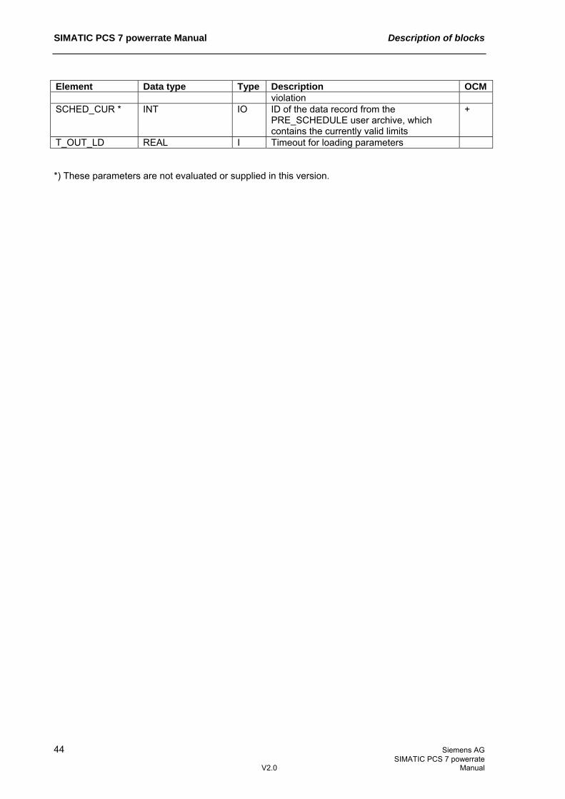
SIMATIC PCS 7 powerrate Manual Description of blocks
44 Siemens AG SIMATIC PCS 7 powerrate V2.0 Manual
Element Data type Type Description OCM violation
SCHED_CUR * INT IO ID of the data record from the PRE_SCHEDULE user archive, which contains the currently valid limits
+
T_OUT_LD REAL I Timeout for loading parameters *) These parameters are not evaluated or supplied in this version.

Description of blocks SIMATIC PCS 7 powerrate Manual
Siemens AG 45 SIMATIC PCS 7 powerrate Manual V2.0
3.6.8 Description of icon and faceplate Block icon
The following parameters are displayed: Element Parameter Description Power – Trend EST_PWR The calculated trend at the end of the period Limit HYS_LIMP The currently valid limit Faceplate The faceplate available is described in this chapter.
The following views are available: Overview OVERVIEW Standard STANDARD Energy ENERGY Parameter PARAMETERS Bar para. BAR_PARA Tariffs TARIFFS Priority list PRIOLIST Edit prio list EDITPRIOLIST Configuration CONFIG Messages The file name is composed as follows: @PG_PRE_LMGM_<view>.PDL
The PCS 7 standard display is used for the messages view.
The structure of the individual views of faceplates is described below.

SIMATIC PCS 7 powerrate Manual Description of blocks
46 Siemens AG SIMATIC PCS 7 powerrate V2.0 Manual
Standard (STANDARD)
This view shows the current load management status, based on calculated power values.
The following parameters are displayed: Element Parameter Description Power – act. CUR_PWR The current supply power, shown as a bar graph Power – Trend EST_PWR The calculated trend at the end of the period, shown
as a bar graph Limit HYS_LIMP The currently valid limit, shown as a bar graph Difference P_DIFF The difference between the trend and the current limit,
shown as a bar graph Power – Actual CUR_PWR The current supply power, shown as a value Power – Trend EST_PWR The calculated trend at the end of the period Limit HYS_LIMP The currently valid limit Difference P_DIFF The difference between the trend and the current limit,
shown as a value shed / add shed P_SHED The disconnect power still available according to the
priority list add P_ON The connect power still available according to the
priority list

Description of blocks SIMATIC PCS 7 powerrate Manual
Siemens AG 47 SIMATIC PCS 7 powerrate Manual V2.0
Energy (ENERGY)
This view shows the current load management status, based on calculated energy (work) values.
The following parameters are displayed: Element Parameter Description Energy – act. CUR_VAL The current supply energy, shown as a bar graph Energy – Trend EST_VAL The calculated trend at the end of the period, shown
as a bar graph Limit HYS_LIMW The currently valid limit, shown as a bar graph Difference W_DIFF The difference between the trend and the current limit,
shown as a bar graph Energy – Actual CUR_VAL The current supply energy, shown as a value Energy – Trend EST_PWR The calculated trend at the end of the period Limit HYS_LIMW The currently valid limit Difference W_DIFF The difference between the trend and the current limit,
shown as a value shed / add shed W_SHED The disconnect energy still available according to the
priority list add W_ON The connect energy still available according to the
priority list

SIMATIC PCS 7 powerrate Manual Description of blocks
48 Siemens AG SIMATIC PCS 7 powerrate V2.0 Manual
Parameters (PARAMETERS)
General load management parameters can be set in this view.
Element Parameter Description Limit source SEL_PW Specifies whether the limit will be defined as energy
(work) or power. Release of load shed EN_SHED If this box is checked, loads are released/held in
accordance with the priority list. If the box is not checked, only a trend calculation and limit monitoring are performed, i.e. corresponding messages are output if a limit is about to be exceeded.
Stabilization delay SETTLE_T Specifies the time which must elapse following release/hold before a new signal can be set.
Hysteresis starting value
HYS_PW % value based on the current limit for the hysteresis starting value at the start of the period
Hysteresis time window
HYS_T Time until hysteresis reached 0, i.e. until the specified limit is used as a basis
Suppression time SUPP_T Time which must elapse from the start of the period before load management becomes active

Description of blocks SIMATIC PCS 7 powerrate Manual
Siemens AG 49 SIMATIC PCS 7 powerrate Manual V2.0
Element Parameter Description Period synchro. SYNC_PER Time for the specified limit (for electricity, usually
15 min); this value is configured at the PRE_SUM block.
Threshold Specifies when a warning or alarm will be output. The values are given as percentages of the specified limit.
Warning threshold LIM_WRN % value of the limit after which a warning message indicating a limit is about to be exceeded is issued
Alarm threshold LIM_ALM % value of the limit after which an alarm message indicating a limit is about to be exceeded is issued
Bar para. (BAR_PARA)
The limits for bar graphs displayed in the standard view are specified in this view.
The following parameters are displayed: Element Parameter Description Bargraph upper limit Power CUR_PWRHR Bar graph upper limit for power Energy CUR_VALHR Bar graph upper limit for energy Diff. bargraph upper limit Power P_DIFFHLR Bar graph upper limit for difference in power Energy W_DIFFHLR Bar graph upper limit for difference in energy

SIMATIC PCS 7 powerrate Manual Description of blocks
50 Siemens AG SIMATIC PCS 7 powerrate V2.0 Manual
Tariffs (TARIFFS) This view shows the current tariff and enables the individual tariff limits to be changed.
Element Parameter Description Active tariff Power LIM_P Shows the currently valid tariff as power. Energy LIM_W Shows the currently valid tariff as energy. On-peak tariff/ off-peak tariff
BEG_HT/BEG_LT The duration of the on-peak tariff and the power limit which is valid during this time can be specified here. The power is automatically converted into energy and displayed, based on the period time.
On-peak tariff Power LIM_P_H Power limit for on-peak tariff Energy LIM_W_H Energy limit for on-peak tariff Off-peak tariff Power LIM_P_L Power limit for off-peak tariff Energy LIM_W_L Energy limit for off-peak tariff Holiday tariff LIM_P_SH/ The limit for the holiday tariff can be specified here. A

Description of blocks SIMATIC PCS 7 powerrate Manual
Siemens AG 51 SIMATIC PCS 7 powerrate Manual V2.0
Element Parameter Description LIM_W_SH period of validity is not needed here, as the holiday tariff
always runs from 00:00 to 24:00. Priority list (PRIOLIST)
This view shows the current status of the individual loads in load management mode and allows the user to remove certain loads from load management control and to release them manually.
Element Parameter Description Consumer load name NAMEx Shows the name of the load. Available QONx Indicates whether the load is currently released via
load management or not. Load management EN_SHEDx Defines whether the load is included in load
management control or not. In manual MANx Defines whether the load can be released manually or
not. Manual add MAN_ENx This manually releases the load so that it is no longer
under load management control. Nominal power Px Shows the load's calculated power, provided it exists. Connected ONx Shows the status of the load, provided the load has
status feedback.

SIMATIC PCS 7 powerrate Manual Description of blocks
52 Siemens AG SIMATIC PCS 7 powerrate V2.0 Manual
Element Parameter Description Capacity CAPx Contains the load's configured rated power. Priority PRIOx Shows the load's priority, which is used for holding. Rolling sequence ROLLx Specifies the sequence in which loads of the same
priority are disconnected in a rolling process. If loads have the same priority and rolling sequence, they are switched together as a group.
x=01..100 Detailed information is available for every load, including the configured hold times and the type of load, i.e. whether the load features power feedback (=1), status feedback (=2), or no feedback (=3).
Element Parameter Description Type of load MODEx Load type/mode:
0=No load present, 1=Actual power of the load is connected at the Px input, 2=Switching state of the load is connected at the ONx input, 3=Only the load's rated power is known
min. connect time MIN_ONx Minimum time the load must be released before it can be held again
min. connect time active
QMIN_ONx 1=Minimum connect time has not yet elapsed
min. disconnect time MIN_OFFx Minimum time the load must be held before it can be released again
min. disconnect time active
QMIN_OFFx 1=Minimum disconnect time has not yet elapsed
max. disconnect time MAX_OFFx Maximum time the load may be held max. disconnect time active
QMAX_OFFx 1=Maximum disconnect time has not yet elapsed
x=01..100

Description of blocks SIMATIC PCS 7 powerrate Manual
Siemens AG 53 SIMATIC PCS 7 powerrate Manual V2.0
Edit priority list (EDITPRIOLIST)
This view allows the user to edit load parameters and to load the current configuration from the PLC.

SIMATIC PCS 7 powerrate Manual Description of blocks
54 Siemens AG SIMATIC PCS 7 powerrate V2.0 Manual
Element Parameter Description Acquisition type MODEx Load status feedback:
0: No load present 1: Power feedback 2: Status feedback 3: No feedback
Capacity CAPx Load's rated power min. connect time MIN_ONx Minimum time the load must be released before it can
be held again min. disconnect time MIN_OFFx Minimum time the load must be held before it can be
released again max. disconnect time MAX_OFFx Maximum time the load may be held Priority PRIOx Shows the load's priority, which is used for holding. Rolling sequence ROLLx Specifies the sequence in which loads of the same
priority are disconnected in a rolling process. If loads have the same priority and rolling sequence, they are switched together as a group.
x=01..100

Description of blocks SIMATIC PCS 7 powerrate Manual
Siemens AG 55 SIMATIC PCS 7 powerrate Manual V2.0
Configuration (CONFIG) The entire load management configuration is displayed in this list, and can be printed out.

SIMATIC PCS 7 powerrate Manual Description of blocks
56 Siemens AG SIMATIC PCS 7 powerrate V2.0 Manual
3.7 PRE_AS_SEND: AS-to-AS communication FB1070
3.7.1 Calling blocks The OB alarm in which you install the block (e.g. OB32). Also in OB100 (see startup characteristics).
3.7.2 Called blocks
The block calls the following blocks:
FB1074 PRE_BS SFB35 ALARM_8P SFC6 RD_SINFO
3.7.3 Function The block uses S7 communication (BSEND) to send data to another S7 station (BRCV). A maximum of 30 REAL values and 30 binary values can be sent. Each value also has a binary quality code, which specifies whether the measured value is free of errors or not. Quality code The QC_Rx and QC_Bx (x=1..30) parameters contain the quality codes of the input signals and must be connected to the QUALITY output of the associated driver blocks when using the input signals selected.
3.7.4 Message behavior
PRE_AS_SEND issues the following messages: Message block
Message number
Block parameter
Message text Message class
1 QERR Communication error PLC pr ctrl error 2 MSG_2 - - 3 MSG_3 - - 4 MSG_4 - - 5 MSG_5 - - 6 MSG_6 - - 7 MSG_7 - -
MSG_EVID
8 MSG_8 - - The auxiliary values of the message blocks are assigned as follows: Message block Auxiliary
value Parameter Description
1 QSTATUS Data transfer status 2 AUX_PR02 Free 3 AUX_PR03 Free 4 AUX_PR04 Free 5 AUX_PR05 Free 6 AUX_PR06 Free 7 AUX_PR07 Free 8 AUX_PR08 Free 9 AUX_PR09 Free
MSG_EVID
10 AUX_PR10 Free The auxiliary values (AUX_PRx, x=02..10) of the message block can be freely assigned.

Description of blocks SIMATIC PCS 7 powerrate Manual
Siemens AG 57 SIMATIC PCS 7 powerrate Manual V2.0
3.7.5 Error behavior Monitoring the send process The connection with the partner station is monitored. When an error is detected, the QERR output is set and a summary event is sent to the OS. The QSTATUS status is also sent as an auxiliary value, which indicates the precise cause of the error. A message is not generated until the SUPPTIME (suppression time) has elapsed. This parameter is adjustable. The send error is reset when at least one telegram containing valid data has been successfully sent. If SUPPTIME < SAMPLE_T, the error message is generated immediately.
3.7.6 Startup characteristics The RUNUPCYC parameter can be used to set for how long (number of cycles) messages are to be suppressed. RESTART = TRUE can be used to simulate a restart.
3.7.7 Block parameters Element Data type Type Description OCM AUX_PRx ANY IO Auxiliary value 02 - 10 BOOLx REAL I BOOL values 1 - 30 DONE BOOL O Data transfer complete ERR_COUNT DINT IO Error counter FIRST_VAR BOOL I Start of send data HISTLAST_ STATUS
WORD O Status of the last error
HISTLAST_TIME_STAMP
DATE_AND_TIME O Time stamp of the last error
HISTx_STATUS WORD O Status of errors 1 - 4 HISTx_TIME_ STAMP
DATE_AND_TIME O Time stamp of errors 1 - 4
ID WORD I Connection ID L_MSGLCK BOOL I Central message suppression can be
connected
LAST_VAR BOOL I End of send data LEN_COUNT DINT IO Integration of the sent data count MODE BYTE I 0=Send once
1=Send cyclically 2 – 255=Send every nth cycle
MSG_ACK WORD O Messages acknowledged MSG_EVID DWORD I MESSAGE ID/ALARM_8P event ID MSG_STAT WORD O STATUS output MSG_x BOOL I Message input 2 - 8 QC_Bx BYTE I Quality code BOOL value 1 – 30 QC_Rx BYTE I Quality code REAL value 1 – 30 QERR BOOL O 1=Error during data transfer QLEN INT O Length of the sent data QMSG_ERR BOOL O ALARM_8P error QMSG_SUP BOOL O Message suppression QSTATUS INT O Data transfer status R_ID DWORD I Request ID for connection REALx REAL I REAL values 1 - 30 RES_HIST BOOL IO Reset history RESTART BOOL I Manual startup RUNUPCYC INT I Number of startup cycles

SIMATIC PCS 7 powerrate Manual Description of blocks
58 Siemens AG SIMATIC PCS 7 powerrate V2.0 Manual
Element Data type Type Description OCM SAMPLE_T REAL I Sampling time in [s] SUPPTIME REAL I Suppression time in [s] SWITCH BOOL I 1=Send Description of the status xSTATUS Description 11 Warning: New job not active because the previous job is still busy. 25 Communication has started. The job is being processed. 1 Communication problems, e.g. connection description not loaded (local or remote),
connection interrupted (e.g. cable, CPU off, CP in STOP mode) 2 Negative acknowledgment from partner SFB. The function cannot be �executed. 3 R_ID is unknown on the connection specified by the ID or the receive block �has not yet
been called. 4 Error in the send area pointer SD_1 regarding data length or data �type, or the value 0
was transferred with LEN. 5 Reset request was executed. 6 The status of the partner SFB is DISABLED (value of EN_R is 0). 7 The status of the partner SFB is not correct (receive block not called since last data
transfer). 8 Access to remote object in the user memory was rejected: The destination area at the
associated SFB13 "BRCV" is too small (ERROR = 1, STATUS = 4 is reported at the associated SFB13 "BRCV").
10 Access to local user memory not possible (for example, access to deleted DB). 12 When the SFB was called, an instance DB that does not belong to SFB12 was specified,
a shared DB was specified instead of an instance DB, no instance DB was found (loading a new instance DB from the PG).
18 R_ID already exists in the connection. 20 Insufficient work memory -1 Connection error FIRST_VAR and/or LAST_VAR -2 Internal error SFC20 BLKMOV -3 Internal error SFC20 BLKMOV: Destination area too small -4 Internal error SFC6 RD_SINFO

Description of blocks SIMATIC PCS 7 powerrate Manual
Siemens AG 59 SIMATIC PCS 7 powerrate Manual V2.0
3.8 PRE_AS_RECV: AS-to-AS communication
FB1071
3.8.1 Calling blocks The OB alarm in which you install the block (e.g. OB32). Also in OB100 (see startup characteristics).
3.8.2 Called blocks
The block calls the following blocks:
FB1075 PRE_BR SFC6 RD_SINFO SFB35 ALARM_8P
3.8.3 Function The block uses S7 communication (BRCV) to receive data from another S7 station (BSEND). A maximum of 30 REAL values and 30 binary values can be sent. Each value also has a binary quality code, which specifies whether the measured value is free of errors or not. Quality code The QC_Rx and QC_Bx (x=1..30) parameters contain the quality codes of the input signals and must be connected to the QUALITY output of the associated driver blocks when using the input signals selected. In addition to the quality codes received, the quality code also provides the following information: Quality code = 16#14: Communication error, last valid value Quality code = 16#18: Communication error, no valid value available
3.8.4 Message behavior
PRE_AS_RECV issues the following messages: Message block
Message number
Block parameter
Message text Message class
1 QERR Communication error PLC pr ctrl error2 MSG_2 - - 3 MSG_3 - - 4 MSG_4 - - 5 MSG_5 - - 6 MSG_6 - - 7 MSG_7 - -
MSG_EVID
8 MSG_8 - -

SIMATIC PCS 7 powerrate Manual Description of blocks
60 Siemens AG SIMATIC PCS 7 powerrate V2.0 Manual
The auxiliary values of the message blocks are assigned as follows: Message block Auxiliary
value Parameter Description
1 QSTATUS Data transfer status 2 AUX_PR02 Free 3 AUX_PR03 Free 4 AUX_PR04 Free 5 AUX_PR05 Free 6 AUX_PR06 Free 7 AUX_PR07 Free 8 AUX_PR08 Free 9 AUX_PR09 Free
MSG_EVID
10 AUX_PR10 Free The auxiliary values (AUX_PRx, x=02..10) of the message block can be freely assigned.
3.8.5 Error behavior Monitoring the receive process The connection with the partner station is monitored. When an error is detected, the QERR output is set and a summary event is sent to the OS. The QSTATUS status is also sent as an auxiliary value, which indicates the precise cause of the error. A message is not generated until the SUPPTIME (suppression time) has elapsed. This parameter is adjustable. The send error is reset when at least one telegram containing valid data has been successfully sent. If SUPPTIME < SAMPLE_T, the error message is generated immediately.
3.8.6 Startup characteristics The RUNUPCYC parameter can be used to set for how long (number of cycles) messages are to be suppressed. RESTART = TRUE can be used to simulate a restart.
3.8.7 Block parameters Element Data type Type Description OCM AUX_PRx ANY IO Auxiliary value 02 - 10 BOOLx REAL O BOOL values 1 - 30 for connection ERR_COUNT DINT IO Error counter FIRST_VAR BOOL IO Start of receive data HISTLAST_ STATUS
WORD O Status of the last error
HISTLAST_TIME_STAMP
DATE_AND_TIME O Time stamp of the last error
HISTx_STATUS WORD O Status of errors 1 - 4 HISTx_TIME_ STAMP
DATE_AND_TIME O Time stamp of errors 1 - 4
ID WORD I Connection ID IN_BOOLx REAL O BOOL values 1 - 30 receive buffer IN_QC_Bx BYTE O Quality code BOOL value 1 – 30 receive
buffer
IN_QC_Rx BYTE O Quality code REAL value 1 – 30 receive buffer

Description of blocks SIMATIC PCS 7 powerrate Manual
Siemens AG 61 SIMATIC PCS 7 powerrate Manual V2.0
Element Data type Type Description OCM IN_REALx REAL O REAL values 1 - 30 receive buffer L_MSGLCK BOOL I Central message suppression can be
connected
LAST_VAR BOOL I End of receive data LEN_COUNT DINT IO Integration of the sent data count MSG_ACK WORD O Messages acknowledged MSG_EVID DWORD I MESSAGE ID/ALARM_8P event ID MSG_STAT WORD O STATUS output MSG_x BOOL I Message input 2 - 8 NDR BOOL O Receive new data QC_Bx BYTE O Quality code BOOL value 1 – 30 QC_Rx BYTE O Quality code REAL value 1 – 30 QERR BOOL O 1=Error during data transfer QLEN INT O Length of the received data QMSG_ERR BOOL O ALARM_8P error QMSG_SUP BOOL O Message suppression QSTATUS INT O Data transfer status R_ID DWORD I Request ID for connection REALx REAL O REAL values 1 - 30 for connection RES_HIST BOOL IO Reset history RESTART BOOL I Manual startup RUNUPCYC INT I Number of startup cycles SAMPLE_T REAL I Sampling time in [s] SUPPTIME REAL I Suppression time in [s] Description of the status xSTATUS Description 11 Warning: New job not active because the previous job is still busy. 17 Warning: Block receiving data asynchronously. 25 Communication has started. The job is being processed. 1 Communication problems, e.g. connection description not loaded (local or remote),
connection interrupted (e.g. cable, CPU off, CP in STOP mode) 2 The function cannot be executed. 4 Error in the receive area pointer RD_1 regarding data length or data type (data block sent
is longer than receive area). 5 Reset request received, incomplete transfer. 8 Access error in the corresponding SFB12 "BSEND": The data packet to be sent is larger
than 452 bytes and after the first data segment is sent, ERROR = 1 and STATUS = 4 are reported.
10 Access to local user memory not possible (for example, access to deleted DB). 12 When the SFB was called, an instance DB that does not belong to SFB13 was specified.
A shared DB was specified instead of an instance DB. No instance DB was found (loading a new instance DB from the PG).
18 R_ID already exists in the connection. 20 Insufficient work memory -1 Connection error FIRST_VAR and/or LAST_VAR -2 Internal error SFC20 BLKMOV -3 Internal error SFC20 BLKMOV: Destination area too small -4 Internal error SFC6 RD_SINFO

SIMATIC PCS 7 powerrate Manual Description of blocks
62 Siemens AG SIMATIC PCS 7 powerrate V2.0 Manual
3.9 PRE_SND_H: AS-4xxH to AS-4xx communication FB1072
3.9.1 Calling blocks The OB alarm in which you install the block (e.g. OB32). Also in OB100 (see startup characteristics).
3.9.2 Called blocks
The block calls the following blocks:
FB1074 PRE_BS SFB35 ALARM_8P SFC6 RD_SINFO
3.9.3 Function The block coordinates the process of sending telegrams between a redundant and a non-redundant automation station by means of S7 communication (BSEND). A maximum of 30 REAL values and 30 binary values can be sent. Each value also has a binary quality code, which specifies whether the measured value is free of errors or not.
Quality code The QC_Rx and QC_Bx (x=1..30) parameters contain the quality codes of the input signals and must be connected to the QUALITY output of the associated driver blocks when using the input signals selected.
AS-4xxH AS-4xx
Connection #1
Connection #2
Send direction PRE_RCV_H
Send direction PRE_RCV_H
PRE_SND_H
PRE_SND_H

Description of blocks SIMATIC PCS 7 powerrate Manual
Siemens AG 63 SIMATIC PCS 7 powerrate Manual V2.0
3.9.4 Message behavior
PRE_SND_H issues the following messages: Message block
Message number
Block parameter
Message text Message class
1 QERR_1 Communication error, connection 1 PLC pr ctrl error 2 QERR_2 Communication error, connection 2 PLC pr ctrl error 3 QERR_1,
QERR_2 Total communication failure PLC pr ctrl error
4 MSG_4 - - 5 MSG_5 - - 6 MSG_6 - - 7 MSG_7 - -
MSG_EVID
8 MSG_8 - - The auxiliary values of the message blocks are assigned as follows: Message block Auxiliary
value Parameter Description
1 QSTATUS_1 Data transfer status, connection 1 2 QSTATUS_2 Data transfer status, connection 2 3 AUX_PR03 Free 4 AUX_PR04 Free 5 AUX_PR05 Free 6 AUX_PR06 Free 7 AUX_PR07 Free 8 AUX_PR08 Free 9 AUX_PR09 Free
MSG_EVID
10 AUX_PR10 Free The auxiliary values (AUX_PRx, x=03..10) of the message block can be freely assigned.
3.9.5 Error behavior Monitoring the send process The two connections to the receiving partner are monitored separately. The block usually sends data via both connections simultaneously. When an error is detected, the relevant QERR_1/QERR_2 output is set and a summary event is sent to the OS. Following a total failure of both connections, the auxiliary value (quality code) supplied for every value is also activated. A message is not generated until the SUPPTIME (suppression time) has elapsed. This parameter is adjustable. The send error is reset when at least one telegram containing valid data has been successfully sent. If SUPPTIME < SAMPLE_T, the error message is generated immediately.
3.9.6 Startup characteristics The RUNUPCYC parameter can be used to set for how long (number of cycles) messages are to be suppressed. RESTART = TRUE can be used to simulate a restart.

SIMATIC PCS 7 powerrate Manual Description of blocks
64 Siemens AG SIMATIC PCS 7 powerrate V2.0 Manual
3.9.7 Block parameters Element Data type Type Description OCM AUX_PRx ANY IO Auxiliary value 03 - 10 BOOLx REAL I BOOL values 1 - 30 DONE_x BOOL O Data transfer complete, connection x ERR_CNT_x DINT O Error counter, connection x FIRST_VAR BOOL I Start of send data HISTLAST_STATUS
WORD O Status of the last error, connection x
HISTLAST_TIME_STAMP_x
DATE_AND_TIME O Time stamp of the last error, connection x
HISTx_STATUS_x WORD O Status of errors 1 - 4, connection x HISTx_TIME_STAMP_x
DATE_AND_TIME O Time stamp of errors 1 - 4
ID_1 WORD I Connection ID, connection 1 ID_2 WORD I Connection ID, connection 2 L_MSGLCK BOOL I Central message suppression can be
connected
LAST_VAR BOOL I End of send data LEN_CNT_x DINT O Integration of the sent data count,
connection x
MODE BYTE I 0=Send once 1=Send cyclically 2 – 255=Send every nth cycle
MSG_ACK WORD O Messages acknowledged MSG_EVID DWORD I MESSAGE ID/ALARM_8P event ID MSG_STAT WORD O STATUS output MSG_x BOOL I Message input 4 - 8 QC_Bx BYTE O Quality code BOOL value 1 – 30 QC_Rx BYTE O Quality code REAL value 1 – 30 QERR_x BOOL O 1=Error during data transfer, connection x QLEN_x INT O Length of the sent data, connection x QMSG_ERR BOOL O ALARM_8P error QMSG_SUP BOOL O Message suppression QSTATUS_x INT O Data transfer status, connection x R_ID_1 DWORD I Request ID for connection 1 R_ID_2 DWORD I Request ID for connection 2 REALx REAL I REAL values 1 - 30 RES_HI_1 BOOL IO Reset history, connection 1 RES_HI_2 BOOL IO Reset history, connection 2 RESTART BOOL I Manual startup RUNUPCYC INT I Number of startup cycles SAMPLE_T REAL I Sampling time in [s] SUPPTIME REAL I Suppression time in [s] SWITCH BOOL I 1=Send

Description of blocks SIMATIC PCS 7 powerrate Manual
Siemens AG 65 SIMATIC PCS 7 powerrate Manual V2.0
Description of the status XSTATUS Description 11 Warning: New job not active because the previous job is still busy. 25 Communication has started. The job is being processed. 1 Communication problems, e.g. connection description not loaded (local or remote),
connection interrupted (e.g. cable, CPU off, CP in STOP mode) 2 Negative acknowledgment from partner SFB. The function cannot be �executed. 3 R_ID is unknown on the connection specified by the ID or the receive block �has not yet
been called. 4 Error in the send area pointer SD_1 regarding data length or data �type, or the value 0
was transferred with LEN. 5 Reset request was executed. 6 The status of the partner SFB is DISABLED (value of EN_R is 0). 7 The status of the partner SFB is not correct (receive block not called since last data
transfer). 8 Access to remote object in the user memory was rejected: The destination area at the
associated SFB13 "BRCV" is too small (ERROR = 1, STATUS = 4 is reported at the associated SFB13 "BRCV").
10 Access to local user memory not possible (for example, access to deleted DB). 12 When the SFB was called, an instance DB that does not belong to SFB12 was specified,
a shared DB was specified instead of an instance DB, no instance DB was found (loading a new instance DB from the PG).
18 R_ID already exists in the connection. 20 Insufficient work memory -1 Connection error FIRST_VAR and/or LAST_VAR -2 Internal error SFC20 BLKMOV -3 Internal error SFC20 BLKMOV: Destination area too small -4 Internal error SFC6 RD_SINFO

SIMATIC PCS 7 powerrate Manual Description of blocks
66 Siemens AG SIMATIC PCS 7 powerrate V2.0 Manual
3.10 PRE_RCV_H: AS-4xxH to AS-4xx communication
FB1073
3.10.1 Calling blocks The OB alarm in which you install the block (e.g. OB32). Also in OB100 (see startup characteristics).
3.10.2 Called blocks
The block calls the following blocks:
FB1075 PRE_BR SFB35 ALARM_8P SFC6 RD_SINFO
3.10.3 Function The block coordinates the process of receiving telegrams between a redundant and a non-redundant automation station by means of S7 communication (BRCV). A maximum of 30 REAL values and 30 binary values can be sent. Each value also has a binary quality code, which specifies whether the measured value is free of errors or not.
Quality code The QC_Rx and QC_Bx (x=1..30) parameters contain the quality codes of the input signals and must be connected to the QUALITY output of the associated driver blocks when using the input signals selected. In addition to the quality codes received, the quality code also provides the following information: Quality code = 16#14: Communication error, last valid value Quality code = 16#18: Communication error, no valid value available
AS-4xxH AS-4xx
Connection #1
Connection #2
Send direction PRE_RCV_H
Send direction PRE_RCV_H
PRE_SND_H
PRE_SND_H

Description of blocks SIMATIC PCS 7 powerrate Manual
Siemens AG 67 SIMATIC PCS 7 powerrate Manual V2.0
3.10.4 Message behavior
PRE_RCV_H issues the following messages: Message block
Message number
Block parameter
Message text Message class
1 QERR_1 Communication error, connection 1 PLC pr ctrl error2 QERR_2 Communication error, connection 2 PLC pr ctrl error3 QERR_1,
QERR_2 Total communication failure PLC pr ctrl error
4 MSG_4 - - 5 MSG_5 - - 6 MSG_6 - - 7 MSG_7 - -
MSG_EVID
8 MSG_8 - - The auxiliary values of the message blocks are assigned as follows: Message block Auxiliary
value Parameter Description
1 QSTATUS_1 Data transfer status, connection 1 2 QSTATUS_2 Data transfer status, connection 2 3 AUX_PR03 Free 4 AUX_PR04 Free 5 AUX_PR05 Free 6 AUX_PR06 Free 7 AUX_PR07 Free 8 AUX_PR08 Free 9 AUX_PR09 Free
MSG_EVID
10 AUX_PR10 Free The auxiliary values (AUX_PRx, x=03..10) of the message block can be freely assigned.
3.10.5 Error behavior Monitoring the receive process The two connections to the sending partner are monitored separately. If the process is functioning without errors, the receive data is transferred from the first connection; if one connection fails, the data is transferred from whichever of the two connections still exists. When an error is detected, the relevant QERR_1/QERR_2 output is set and a summary event is sent to the OS. Following a total failure of both connections, the auxiliary value (quality code) supplied for every value is also activated. A message is not generated until the SUPPTIME (suppression time) has elapsed. This parameter is adjustable. The send error is reset when at least one telegram containing valid data has been successfully sent. If SUPPTIME < SAMPLE_T, the error message is generated immediately.
3.10.6 Startup characteristics The RUNUPCYC parameter can be used to set for how long (number of cycles) messages are to be suppressed. RESTART = TRUE can be used to simulate a restart.

SIMATIC PCS 7 powerrate Manual Description of blocks
68 Siemens AG SIMATIC PCS 7 powerrate V2.0 Manual
3.10.7 Block parameters Element Data type Type Description OCM AUX_PRx ANY IO Auxiliary value 03 - 10 BOOLx REAL O BOOL values 1 - 30 for connection DUMMY WORD IO Dummy ERR_CNT_1 DINT O Error counter FIRST_VAR_1 BOOL IO Pointer initial value, connection 1 FIRST_VAR_2 BOOL IO Pointer initial value, connection 2 HISTLAST_ STATUS_x
WORD O Status of the last error, connection x
HISTLAST_TIME_STAMP_x
DATE_AND_TIME O Time stamp of the last error, connection x
HISTx_STATUS_x WORD O Status of errors 1 - 4, connection x HISTx_TIME_ STAMP_x
DATE_AND_TIME O Time stamp of errors 1 - 4, connection x
ID_1 WORD I Connection ID, connection 1 ID_2 WORD I Connection ID, connection 2 IN_BOOLx_1 REAL IO BOOL values 1 - 30 for readback IN_BOOLx_2 REAL IO BOOL values 1 - 30 for readback IN_QC_Bx_1 BYTE IO Quality code BOOL value 1 – 30 for
readback
IN_QC_Bx_2 BYTE IO Quality code BOOL value 1 – 30 for readback
IN_QC_Rx_1 BYTE IO Quality code REAL value 1 – 30 for readback
IN_QC_Rx_2 BYTE IO Quality code REAL value 1 – 30 for readback
IN_REALx_1 REAL IO REAL values 1 - 30 for readback IN_REALx_2 REAL IO REAL values 1 - 30 for readback L_ACT_CON BOOL O Last active connection: 0=Connection 1,
1=Connection 2
L_MSGLCK BOOL I Central message suppression can be connected
LAST_VAR_1 BOOL IO End ID receive buffer readback, connection 1
LAST_VAR_2 BOOL IO End ID receive buffer readback, connection 2
LEN_CNT_1 DINT O Integration of the sent data count MSG_ACK WORD O Messages acknowledged MSG_EVID DWORD I MESSAGE ID/ALARM_8P event ID MSG_STAT WORD O STATUS output MSG_x BOOL I Message input 4 - 8 NDR_2 BOOL O Receive new data for connection 2 QC_Bx BYTE O Quality code BOOL value 1 – 30 QC_Rx BYTE O Quality code REAL value 1 – 30 QERR_2 BOOL O 1=Error during data transfer for connection QLEN_2 INT O Length of the received data for connection QMSG_ERR BOOL O ALARM_8P error QMSG_SUP BOOL O Message suppression QSTATUS_2 INT O Data transfer status for connection R_ID_1 DWORD I Request ID for connection 1 R_ID_2 DWORD I Request ID for connection 2 REALx REAL O REAL values 1 - 30 for connection

Description of blocks SIMATIC PCS 7 powerrate Manual
Siemens AG 69 SIMATIC PCS 7 powerrate Manual V2.0
Element Data type Type Description OCM RES_HI_x BOOL IO Reset history, connection x RESTART BOOL I Manual startup RUNUPCYC INT I Number of startup cycles SAMPLE_T REAL I Sampling time in [s] SUPPTIME REAL I Suppression time in [s] Description of the status xSTATUS Description 11 Warning: New job not active because the previous job is still busy. 17 Warning: Block receiving data asynchronously. 25 Communication has started. The job is being processed. 1 Communication problems, e.g. connection description not loaded (local or remote),
connection interrupted (e.g. cable, CPU off, CP in STOP mode) 2 The function cannot be executed. 4 Error in the receive area pointer RD_1 regarding data length or data type (data block sent
is longer than receive area). 5 Reset request received, incomplete transfer. 8 Access error in the corresponding SFB12 "BSEND": The data packet to be sent is larger
than 452 bytes and after the first data segment is sent, ERROR = 1 and STATUS = 4 are reported.
10 Access to local user memory not possible (for example, access to deleted DB). 12 When the SFB was called, an instance DB that does not belong to SFB13 was specified.
A shared DB was specified instead of an instance DB. No instance DB was found (loading a new instance DB from the PG).
18 R_ID already exists in the connection. 20 Insufficient work memory -1 Connection error FIRST_VAR and/or LAST_VAR -2 Internal error SFC20 BLKMOV -3 Internal error SFC20 BLKMOV: Destination area too small -4 Internal error SFC6 RD_SINFO

SIMATIC PCS 7 powerrate Manual Description of blocks
70 Siemens AG SIMATIC PCS 7 powerrate V2.0 Manual
3.11 PRE_BS: Calling the BSEND system function block
FB1074
3.11.1 Calling blocks The block is called internally.
3.11.2 Called blocks
The block calls the following blocks:
SFB12 BSEND SFC1 READ_CLK SFC6 RD_SINFO SFC20 BLKMOV
3.11.3 Function The block forms the internal interface for communication in the send direction.
3.12 PRE_BR: Calling the BRCV system function block
FB1075
3.12.1 Calling blocks The block is called internally.
3.12.2 Called blocks
The block calls the following blocks:
SFB13 BRCV SFC1 READ_CLK SFC6 RD_SINFO SFC20 BLKMOV
3.12.3 Function The block forms the internal interface for communication in the receive direction.

Description of blocks SIMATIC PCS 7 powerrate Manual
Siemens AG 71 SIMATIC PCS 7 powerrate Manual V2.0
3.13 PRE_CALC: Calculations
FC1061
3.13.1 Calling blocks The block is called by the PRE_SUM FB.
3.13.2 Function The PRE_CALC function contains the calculation algorithms which can be used when producing measured values for the PRE_SUM FB. The function is a source in the library and the user can therefore add other calculations to it. The function interface must not be changed. The following algorithms are implemented: CALC_FN function
Algorithm
0 OUT = P0 + P1 * IN1 + P2 * IN2 + P3 * IN3
1 Calculation of heat quantity for liquids OUT = P0 * IN1 * P1 * IN2 where: P0 = specific heat capacity c P1 = density p IN1 = flow V IN2 = difference in temperature ΔT
Assignment input parameters PRE_CALC to input parameters PRE_SUM: PRE_CALC PRE_SUM CALC_FN CALC_FN INx ACTUALx Px CALC_Px
3.13.3 Message behavior The block has no message behavior.
3.13.4 Error behavior The QERR error output is set when - An error is established during the calculation (e.g. division by 0)
3.13.5 Startup characteristics The block has no startup characteristics.

SIMATIC PCS 7 powerrate Manual Description of blocks
72 Siemens AG SIMATIC PCS 7 powerrate V2.0 Manual
3.13.6 Block parameters Element Data type Type Description OCM CALC_FN INT I Calculation function INx REAL I Input value x (x=1..3) Px REAL I Constant x (x=0..3) QERR BOOL O 1=Error OUT REAL O Result
3.14 PRE_FIFO_IO: Organization of FIFO buffer
FC1062
3.14.1 Calling blocks The block is called by the PRE_SUM, PRE_FIFO_DATA, and PRE_AR_SND FBs.
3.14.2 Called blocks
The block calls the following blocks:
SFC24 TEST_DB
3.14.3 Function The PRE_FIFO_IO function organizes reading and writing access on the FIFO buffer, which is represented by the PRE_FIFO_DATA FB. The FIFO contains the functionality of a cyclic buffer. Old data are overwritten when the buffer overflows. The status of the FIFO buffer is displayed at the QEMPTY (buffer empty) and QFULL (buffer full) outputs.
3.14.4 Message behavior The block has no message behavior.
3.14.5 Error behavior The QPARAMF error output is set when - The parameterized FIFO DB is not present - The FIFO DB length is too short
3.14.6 Startup characteristics During initial startup, the block initializes the check data of the FIFO buffer. This call takes place in the PRE_FIFO_DATA FB. When the CPU is started up subsequently, the pointers are retained.
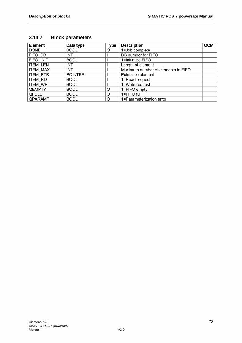
Description of blocks SIMATIC PCS 7 powerrate Manual
Siemens AG 73 SIMATIC PCS 7 powerrate Manual V2.0
3.14.7 Block parameters Element Data type Type Description OCM DONE BOOL O 1=Job complete FIFO_DB INT I DB number for FIFO FIFO_INIT BOOL I 1=Initialize FIFO ITEM_LEN INT I Length of element ITEM_MAX INT I Maximum number of elements in FIFO ITEM_PTR POINTER I Pointer to element ITEM_RD BOOL I 1=Read request ITEM_WR BOOL I 1=Write request QEMPTY BOOL O 1=FIFO empty QFULL BOOL O 1=FIFO full QPARAMF BOOL O 1=Parameterization error

SIMATIC PCS 7 powerrate Manual Description of blocks
74 Siemens AG SIMATIC PCS 7 powerrate V2.0 Manual
3.15 UDT_PRE_FIFO
UDT1060
3.15.1 Description The UDT_PRE_FIFO user data type contains internal check data for organizing the FIFO buffer. The UDT is used internally.
3.15.2 Structure Element Data type Description FIFO_ST DWORD Pointer at start of FIFO FIFO_END DWORD Pointer at end of FIFO WR_POS DWORD Pointer at current write position RD_POS DWORD Pointer at current read position ITEM_CNT INT Counter for elements LOCKED BOOL 1=Access locked SPARE ARRAY [1..4] of
BYTE Reserve
3.16 UDT_PRE_ITEM
UDT1061
3.16.1 Description The UDT_PRE_ITEM user data type contains the storage structure of a measured value. The UDT is used internally.
3.16.2 Structure Element Data type Description TS DATE_AND_TIME Time stamp of measured value VALUE REAL Measured value AR_SNO WORD Subnumber for archive tag

Description of blocks SIMATIC PCS 7 powerrate Manual
Siemens AG 75 SIMATIC PCS 7 powerrate Manual V2.0
3.17 UDT_PRE_TLG
UDT1062
3.17.1 Description The UDT_PRE_TLG user data type contains the structure of a telegram element for sending into the WinCC Tag Logging archive. The UDT is used internally.
3.17.2 Structure Element Data type Description Default HEAD_TYPE WORD Header type 8 : With time stamp CYCLE TIME Cycle 0 : Not relevant U_TYPE BYTE Unit (type) 2 : Each process value has a
time stamp U_AREA BYTE Units (range) 0 : Not relevant AR_SNO WORD Subnumber of archive tag DT_TYPE INT Data type of element 5 : Analog value NO_ITEMS INT Number of elements to be
sent 1
TS DATE_AND_TIME Time stamp of element VALUE REAL Measured value

SIMATIC PCS 7 powerrate Manual Description of the Excel Add-In
76 Siemens AG SIMATIC PCS 7 powerrate V2.0 Manual
4 Description of the Excel Add-In The Excel Add-In reads the selected archive data of the Tag Logging archive from the WinCC Runtime database. Due to WinCC system behavior, it is not currently possible to access swapped archives. The following functions can be executed: - Export: Exports data to Excel without creating a report - Cost center report: Assigns energy values/costs to cost centers - Duration curve report: Represents mean power values as a duration curve The generated reports are created using standard Excel tools and can be easily adapted to meet the prevailing requirements. Note: - As the Add-In writes directly to the cells, the allocation of the cells has to be maintained if the file
is to be reused. - If different types of report are created alternately, the previously created report tabs are deleted
and the appropriate tabs generated from scratch. If the formatting of the reports has been changed, it is advisable to save the modified template file for a particular report type, and to only use it for that type.

Description of the Excel Add-In SIMATIC PCS 7 powerrate Manual
Siemens AG 77 SIMATIC PCS 7 powerrate Manual V2.0
4.1 Cost center report
The reports "Table" and "Chart" are generated to evaluate energy values (.S tags). These reports are used to assign consumption data and costs to the relevant cost centers. When a report is created, the reporting period over which the evaluation is to be performed must be specified. "Table" tab
"Chart" tab

SIMATIC PCS 7 powerrate Manual Description of the Excel Add-In
78 Siemens AG SIMATIC PCS 7 powerrate V2.0 Manual
4.2 Duration curve report
The "Duration curve" report contains the mean power values (.V tags). It shows the frequency with which particular mean power values occur. This graphic can then be used to deduce whether temporary power peaks are present. "Duration curve" tab
A detailed description of the Excel Add-In is provided in Chapter 5.3 Configuring the Excel Add-In.

Configuration manual SIMATIC PCS 7 powerrate Manual
Siemens AG 79 SIMATIC PCS 7 powerrate Manual V2.0
5 Configuration manual
5.1 Configuring measuring points for energy/power acquisition
5.1.1 Writing the AS program
The library contains pre-produced CFC templates, which can be used as templates. The CFC charts and the procedure for writing the program are provided below.
The CFC "SYSTEM" chart contains the superordinate blocks which are responsible for time synchronization, data buffering, and data archiving.

SIMATIC PCS 7 powerrate Manual Configuration manual
80 Siemens AG SIMATIC PCS 7 powerrate V2.0 Manual
- Installation of PRE_SYNC block for different synchronization times o Parameterization of type of synchronization (internal/external) o Parameterization of synchronization periods o Parameterization of synchronization pulse periods
- Installation of PRE_FIFO_DATA block for FIFO buffer - Installation of PRE_AR_DATA block for communication with WinCC Tag Logging archive
o Connection with PRE_FIFO_DATA There is one CFC for each signal type: - Pulse input: PULSE_INPUT - Integer counter: INTEGER_COUNTER - Analog counter: ANALOG_COUNTER - Calculation function: CALCULATION

Configuration manual SIMATIC PCS 7 powerrate Manual
Siemens AG 81 SIMATIC PCS 7 powerrate Manual V2.0
- Installation of PRE_SUM block for measuring point o Connection with measured value o Connection with PRE_SYNC block o Connection with PRE_FIFO_DATA o Connection with PRE_AR_DATA o Parameterization of signal type/calculation parameter o Parameterization of subnumbers of archive tags
Since blocks whose numbers are covered by the CFC by default are used, the settings for Compile/Download have to be adjusted in the CFC prior to compiling the program. These changes are carried out in the menu Options > Customize > Compile/Download.
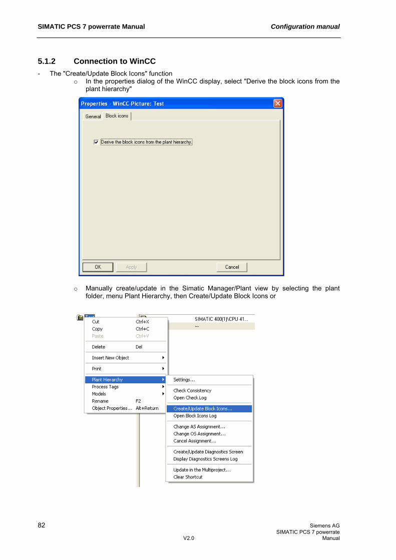
SIMATIC PCS 7 powerrate Manual Configuration manual
82 Siemens AG SIMATIC PCS 7 powerrate V2.0 Manual
5.1.2 Connection to WinCC - The "Create/Update Block Icons" function
o In the properties dialog of the WinCC display, select "Derive the block icons from the plant hierarchy"
o Manually create/update in the Simatic Manager/Plant view by selecting the plant
folder, menu Plant Hierarchy, then Create/Update Block Icons or

Configuration manual SIMATIC PCS 7 powerrate Manual
Siemens AG 83 SIMATIC PCS 7 powerrate Manual V2.0
o Automatically create/update when compiling the OS
- Manually copy the user object from file @Template_PRE.pdl to the process display and run the
"Connect picture block to tag structure" Dynamic Wizard

SIMATIC PCS 7 powerrate Manual Configuration manual
84 Siemens AG SIMATIC PCS 7 powerrate V2.0 Manual
5.1.3 Configuring the process value archive - Create a process value archive with the name pre - Create two process-controlled archive tags for PRE_SUM block
o The names of the archive tags have the following structure: Accumulated work value (LAST_VAL): tagname.S Mean power value (CUR_PWR): tagname.V
tagname matches the tag name of the PRE_SUM block. The names of the archive tags have to be unique throughout the project.
o Enter the unit in [] in the comments box (e.g. [kWh])
o Parameterization of AR_ID with AR_EVID parameter of associated PRE_AR_DATA
archiving block o Parameterization of subnumbers with parameters ARSNO_S (for work value) and
ARSNO_V (for mean power value) of the associated energy acquisition block PRE_SUM

Configuration manual SIMATIC PCS 7 powerrate Manual
Siemens AG 85 SIMATIC PCS 7 powerrate Manual V2.0
- Configuration of Tag Logging Fast:
Process-controlled archive tags are saved by WinCC in Tag Logging Fast. When configuring Tag Logging Fast it has to be taken into account that the application only accesses the runtime archive and archives which have not been swapped out.
The memory requirement of a process-controlled archive tag depends on the archiving cycle. For a 15-minute archiving cycle, it is approx. 1MB per year for one archive tag. In Tag Logging Fast, the acyclic measured values (archiving triggered by result) and cyclic measured values with a cycle <= 1 minute are saved by default in addition to the process-controlled archive tags.

SIMATIC PCS 7 powerrate Manual Configuration manual
86 Siemens AG SIMATIC PCS 7 powerrate V2.0 Manual

Configuration manual SIMATIC PCS 7 powerrate Manual
Siemens AG 87 SIMATIC PCS 7 powerrate Manual V2.0
5.2 Configuring load management
5.2.1 Writing the AS program
The library contains a pre-produced "LMGM" CFC template, which can be used as a template. The CFC charts and the procedure for writing the load management program are provided below.
- Installation of PRE_LMGM block for load management
o Connection of CUR_VAL, CUR_PWR, EST_VAL, EST_PWR, LAST_VAL, AVG_PWR with PRE_SUM block for supply
o Connection with PRE_SYNC block o Connection of load inputs with status (ONx)/power (Px) o Connection of load release signal outputs (QONx) with load's switching logic

SIMATIC PCS 7 powerrate Manual Configuration manual
88 Siemens AG SIMATIC PCS 7 powerrate V2.0 Manual
In the example, a PRE_SUM block is available in the "LMGM" CFC for acquiring the supply power. This block can also be installed in a separate CFC chart.

Configuration manual SIMATIC PCS 7 powerrate Manual
Siemens AG 89 SIMATIC PCS 7 powerrate Manual V2.0
5.2.2 Connection to WinCC See Chapter 5.1.2 Connection to WinCC Loads and limits are parameterized in WinCC (see Chapter 3.6.8 Description of icon and faceplate).
5.2.3 Configuring the user archive in WinCC Configuration files are provided for the user archives required by load management. The files are located in the WinCC installation directory, in folder powerrate\Config, and are available in English and German. The configuration can only use one language. - Importing the configuration
Please use the following files: German: UserArchiveKonfigurationDeutsch.uap English: UserArchiveConfigurationEnglish.uap
Two user archives are created:
o PRE_CONFIG_LIST: List of previous configurations o PRE_PRIO_LIST: Priority list

SIMATIC PCS 7 powerrate Manual Configuration manual
90 Siemens AG SIMATIC PCS 7 powerrate V2.0 Manual
- Importing runtime data for making priority list default settings
A file (PRE_PRIO_LIST.csv) containing archive default settings is provided for the PRE_PRIO_LIST archive. This file can be edited in Excel, if desired, then imported.

Configuration manual SIMATIC PCS 7 powerrate Manual
Siemens AG 91 SIMATIC PCS 7 powerrate Manual V2.0
5.3 Configuring the Excel Add-In
5.3.1 Connection to WinCC The Excel Add-In is called using a button in WinCC. This button is found on the @Template_pre.pdl template display. It must be incorporated in a display on the computer on which the Add-In has been installed.
- Incorporating call button in process display
5.3.2 Starting the Excel Add-In When the button is pressed, the system checks whether the Add-In is installed or not. If it is, Excel and the Add-In are started and the computer name of the server which contains the Tag Logging archive to be processed is transferred. An error message will be displayed in the event of an error. The entry for pre-reporting appears in the Excel menu bar.
The user can now either open an existing file or use the "Read Taglist" menu item to read the archive tags available.
5.3.3 Read Taglist: Reading tag names The "Read Taglist" function performs the following actions:
- Opens the pre_Configuration.xls configuration file - Opens a new DataReading*.xls file for storing data on the basis of the DataReading.xlt
template - Establishes a connection with the WinCC Tag Logging archive selected - Reads the archive data from the Tag Logging archive and stores it in the DataReading*.xls file
5.3.4 Configuring report data The following reports can be created: - Export: Exports data to Excel without creating a report - Cost center report: Assigns energy values/costs to cost centers - Duration curve report: Represents mean power values as a duration curve The PRE Reporting menu contains additional sub-items for the different reports.

SIMATIC PCS 7 powerrate Manual Configuration manual
92 Siemens AG SIMATIC PCS 7 powerrate V2.0 Manual
Procedure for configuring report data: Below you will find information on general settings, followed by report-specific configurations. General configurations - Define the derived tags in pre_Configuration.xls/"Derived Tags" tab and enter calculation
formulas.
The tags used in formulas have to be marked as to be read on the "Settings" tab. If they are not to appear in the report, the tag must not be assigned to a cost center.
If an incorrect formula is entered, the erroneous cell is marked red. Reading of the tag list (Read Taglist function) is interrupted with an error message.
- Running "Read Taglist" again results in a new DataReading*.xls file being generated with modified
settings. - Highlight the archive tags to be read in the DataReading1.xls file/"Settings" tab/"Read" column.
- Parameterize the start and end time, aggregation time, and time zone.
For the start/end time, note that archive values can only be read from archives which have not been swapped. The end time must be after the start time. The aggregation time should not be greater than the archiving cycle of the archive tags, otherwise invalid values could be displayed. This applies in particular to energy values which are entered manually.
Cost center report The cost center report only takes energy values into account. The Add-In identifies such values by the ".S" suffix added to the archive tag name. The following settings must be made: - Copy name of relevant archive tags into pre_Configuration.xls file/"CostCenter" tab/left-hand
column.

Configuration manual SIMATIC PCS 7 powerrate Manual
Siemens AG 93 SIMATIC PCS 7 powerrate Manual V2.0
- Define the cost centers and assignment to the archive tags (double clicking on the cell adds "X").
Every tag can be assigned just one cost center. If 2 cost centers are assigned to a tag, the line is marked red. Reading of the tag list (Read Taglist function) is interrupted with an error message. Tags which are not assigned to a cost center are not taken into account in the report. Note: The cost centers are not present in the WinCC data storage.
- Running "Read Taglist" again results in a new DataReading*.xls file being generated with modified
settings. - Define the tariffs in file DataReading1.xls/"Tariff" tab:
An on- and off-peak tariff can be assigned to individual days of the week/times and holidays. The time is only entered for the on-peak tariff. If the off-peak tariff is assigned to a day, it is applied to the whole day, likewise on holidays. Only whole hours can be entered for time specifications.
- If there is only one tariff, the same value has to be entered in both cells containing the rate
($/kWh).
The data aggregation time (for export to Excel) can be set to 1 hour at most, so that the different tariffs can be taken into account granular on the hour.
Duration curve report Only power values are taken into account in the duration curve report. The Add-In identifies such values by the ".V" suffix added to the archive tag name. Only 1 tag may be selected. This tag must have been archived during the reporting period with a uniform archiving cycle. The aggregation time must be set to "None".

SIMATIC PCS 7 powerrate Manual Configuration manual
94 Siemens AG SIMATIC PCS 7 powerrate V2.0 Manual
5.3.5 Reading archive tags When the DataReading1.xls file is opened, the "Cost center report", "Duration curve report", and "Export" sub-items also appear in the PRE Reporting menu.
In addition to reading out archive tags, the following reports are also created: - Export: Exports data to Excel without creating a report - Cost center report: Assigns energy values/costs to cost centers - Duration curve: Represents mean power values as a duration curve These functions initiate the reading of values from the Tag Logging archive and create the selected reports. The reports are described in Chapter 4 Description of the Excel Add-In. Only values from the WinCC RT archive are read. Files which have already been swapped are not taken into account. The parameters already set for the start/end time, aggregation time, and time zone are displayed in a window and can be adjusted again before the archive values are read.
If mistakes are made during input, the function is not executed and a Msgbox displayed.

Configuration manual SIMATIC PCS 7 powerrate Manual
Siemens AG 95 SIMATIC PCS 7 powerrate Manual V2.0
A progress message box appears during the reading process and is closed at the end.
The values of the archive tags are written along with the time stamp to the "Raw Data" tab and the values of the derived tags are written to the "Derived Data" tab of the DataReading*.xls file. If the data had already been removed at the parameterized start time and are no longer part of the WinCC Runtime archive, the data are read from the earliest time stamp available. Once the data sheets have been filled, the selected report views are generated and supplied with the read values.

SIMATIC PCS 7 powerrate Manual Technical data
96 Siemens AG SIMATIC PCS 7 powerrate V2.0 Manual
6 Technical data The following meanings apply:
Block type name
The symbolic identifier in the library's icon table for the relevant FB. It must be unique to the project.
Object name
Consists of the type of block (FB) and the number.
Block length in load/work memory
Memory requirement of program code, once per block type.
Length of instance data in load/work memory
Memory requirement of an instance DB.
Temporary memory
The local data memory needed when calling the block in an execution level. This is limited depending on the CPU. If exceeded, you must check this in the CPU configuration and, if necessary, redistribute to OBs of the size actually needed.
Called blocks
The blocks stated here are used by the block in question and must be located in the user program. They are saved in the same library.
Block (type name) Number Block length in load/work memory (bytes)
Length of instance data in load/work memory (bytes)
Temporary memory (bytes)
Called blocks
PRE_SYNC FB1060 1302 / 1100 238 / 92 70 FC1 FC34 SFC1 SFC6
PRE_SUM FB1061 6278 / 5446 884 / 440 92 FC1 FC14 FC34 FC1061 FC1062 SFB35 SFC6
PRE_FIFO_DATA * FB1062 470 / 322 14206 / 14066 54 FC1062 SFC6
PRE_AR_DATA * FB1063 464 / 212 736 / 490 22 FB1064

Technical data SIMATIC PCS 7 powerrate Manual
Siemens AG 97 SIMATIC PCS 7 powerrate Manual V2.0
Block (type name) Number Block length in load/work memory (bytes)
Length of instance data in load/work memory (bytes)
Temporary memory (bytes)
Called blocks
PRE_AR_SND FB1064 1524 / 1206 480 / 210 102 FC1062 SFB35 SFB37 SFC6 SFC24
PRE_LMGM FB1065 23266 / 15774 16300 / 9574 276 SFB31 SFB35 SFC6 SFC20 SFC21 SFC51
PRE_AS_SEND FB1070 2174 / 1430 1878 / 1156 44 FB1074 SFB35 SFC6
PRE_AS_RECV FB1071 5616 / 4334 3008 / 1996 46 FB1075 SFB35 SFC6
PRE_SND_H FB1072 3010 / 2070 2692 / 1782 44 FB1074 SFB35 SFC6
PRE_RCV_H FB1073 9820 / 7806 4592 / 3460 44 FB1075 SFB35 SFC6
PRE_BS FB1074 2052 / 1758 792 / 594 38 SFB12 SFC1 SFC6 SFC20
PRE_BR FB1075 1846 / 1590 1374 / 1192 36 SFB13 SFC1 SFC6 SFC20
PRE_CALC * FC1061 358 / 270 - 12 - PRE_FIFO_IO FC1062 1070 / 914 - 22 SFC24 * The technical data relate to the condition of the blocks on delivery. If modified by the user, the data may differ from those provided.
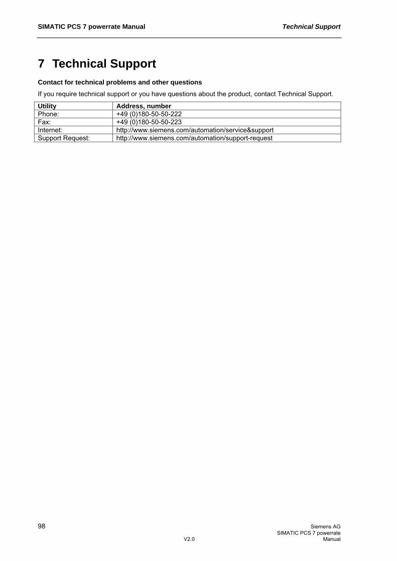
SIMATIC PCS 7 powerrate Manual Technical Support
98 Siemens AG SIMATIC PCS 7 powerrate V2.0 Manual
7 Technical Support Contact for technical problems and other questions
If you require technical support or you have questions about the product, contact Technical Support.
Utility Address, number Phone: +49 (0)180-50-50-222 Fax: +49 (0)180-50-50-223 Internet: http://www.siemens.com/automation/service&support Support Request: http://www.siemens.com/automation/support-request