Embed Size (px)
Citation preview

Signature 1000H+ Cable AnalyzerUser’s Guide
Version 3.0Major Revision
7 September, 1999
Signature 1000H+ Cable Analyzer User’s GuideVersion 3.0
Major Revision7 September, 1999
Copyright 1999 by Cirris Systems Corporation1991 Parkway Boulevard
Salt Lake City, Utah 84119-2026United States of America
All rights reserved
Visit our web site at www.cirris.com
I Need Your Help!
As Senior Editor, it’s my responsibility to constantly improve the manuals and other documentationwe include with our equipment. We try hard, but we know we’ll never please everyone. If you werein my chair, how would you change the documentation to make it better? Here’s your chance to take gripes, suggestions and (we hope) praise directly to the guy who can change things. Please fax or mail this form to me, or contact me by e-mail.
Thanks!
Van NielsonSenior Editor, Technical Documentation
Fax Telephone: 801-973-4609e-mail: [email protected]
Van Nielsonc/o Cirris Systems Corporation1991 Parkway BoulevardSalt Lake City, Utah 84119-2026U.S.A.
1000H+ User’s Guide
Attach more pages if needed

Visit our web site at www.cirris.com
Table of Contents
Introduction to the Cirris 1000H+ .................................................................................... 7
Section 1: Work With the Hardware ................................................................................ 9
Section 2: Check the Option Settings ........................................................................... 17
Section 3: What the Option Settings Mean ................................................................... 19
Section 4: Learn a Sample Cable, Store it in Memory .................................................. 23
Section 5: Test Your First Cable ................................................................................... 27
Section 6: Retrieve a Cable from Memory .................................................................... 31
Section 7: Delete a Cable from Memory ....................................................................... 33
Section 8: Print a Directory of Cables Stored in Memory .............................................. 35
Section 9: Cable Documentation and Signatures ......................................................... 37
Section 10: Select a Test Procedure ............................................................................ 43
Section 11: Rework and Guided Assembly ................................................................... 55
Section 12: Troubleshooting ......................................................................................... 61
Section 13: Specifications ............................................................................................. 71
Section 14: Statement of Warranty ............................................................................... 73
Section 15: Glossary ..................................................................................................... 75
Section 16: Blank Forms to Photocopy ......................................................................... 79
Appendix 1: Four-Wire Testing on the 1000H+ ............................................................ 87
1000H+ User’s Guide / page 5

1000H+ User’s Guide / page 6

to r
you ain.
for
for
d
the
ted a
a 3 x an
Introduction to the Cirris 1000H+
Lets get started! The Cirris 1000H+ cable analyzer is an easy-to-use machine that will allow you test cables quickly, and with little fuss. In simple terms, the process of using you1000H+ goes like this:
1. Install any expansion boxes you want to use (see page 10 for details). Oncehave installed the boxes the first time, you probably won’t have to do this ag
2. Install connector adapters to match the cables you want to test (see page 9 details).
3. Check the test option settings; reset the options if you need to (see page 17details).
4. Either:
• Learn a Sample Cable (a cable you know is built correctly) of the kinyou want to test (see page 23 for details), or...
• Retrieve the wirelist data for the kind of cable you want to test from analyzer’s memory (see page 31 for details)
This completes programming the analyzer for testing cables. If you have connecSample Cable to learn it, disconnect it now.
5. Connect the first cable you want to test.
6. Test the cable (see page 27 for details).
7. Record and/or or print the test results (see page 30 for details).
That’s it! We’ll show you how to do each of these steps in this manual.
What your ordershould contain
Your order should contain these things in addition to this manual:
• 1000H+ main unit, including a wall transformer with cord, to providepower for the analyzer.
• Hand-held test probe.
• Whatever connector adapters you have ordered (usually shipped in 5-inch card file). You may also have ordered an optional tilt stand, oroptional frame stand. If so, these should be included.
• Any expansion boxes you have ordered.
1000H+ User’s Guide / page 7

Introduction to the Cirris 1000H+ / What your order should contain
1000H+ User’s Guide / page 8

ion or
to
or its
and
pter s. To tal r
Section 1: Work With the Hardware
The Cirris 1000H+ system consists of a main unit, and as many as three expansboxes. To connect the cables you want to test to the analyzer, you use connectadapters which match the connectors on the cable you want to test.
In this section, we will explain how to work with the hardware. We will show youhow to install your connector adapters, how to install an expansion box, and howdisassemble the analyzer in case you need to replace one of its subassemblies,EPROM.
How to installconnector adapters
To install connector adapters onto the Cirris 1000H+, follow these steps:
1. Turn the four twistlock fasteners on the adapter cover plate to unlock them, remove the cover plate.
2. Plug in the connector adapters. Be sure the pins on the bottom of each adaare lined up properly, so they don’t bend as they are inserted into the socketline the pins up properly, press the adapter against the inside edge of the meframe, and have the bottom of the adapter card resting on the plastic adaptesupport.
Twistlock fastener unlocked
Twistlock fastener locked
J1
J1
J2
J3
J4
These horizontal pin sockets... accept the adapter connectorpins on the bottom of each adapter
1000H+ User’s Guide / page 9
Section 1: Work With the Hardware / How to install an expansion box
de fit
mber t
e
. ing
e the
er
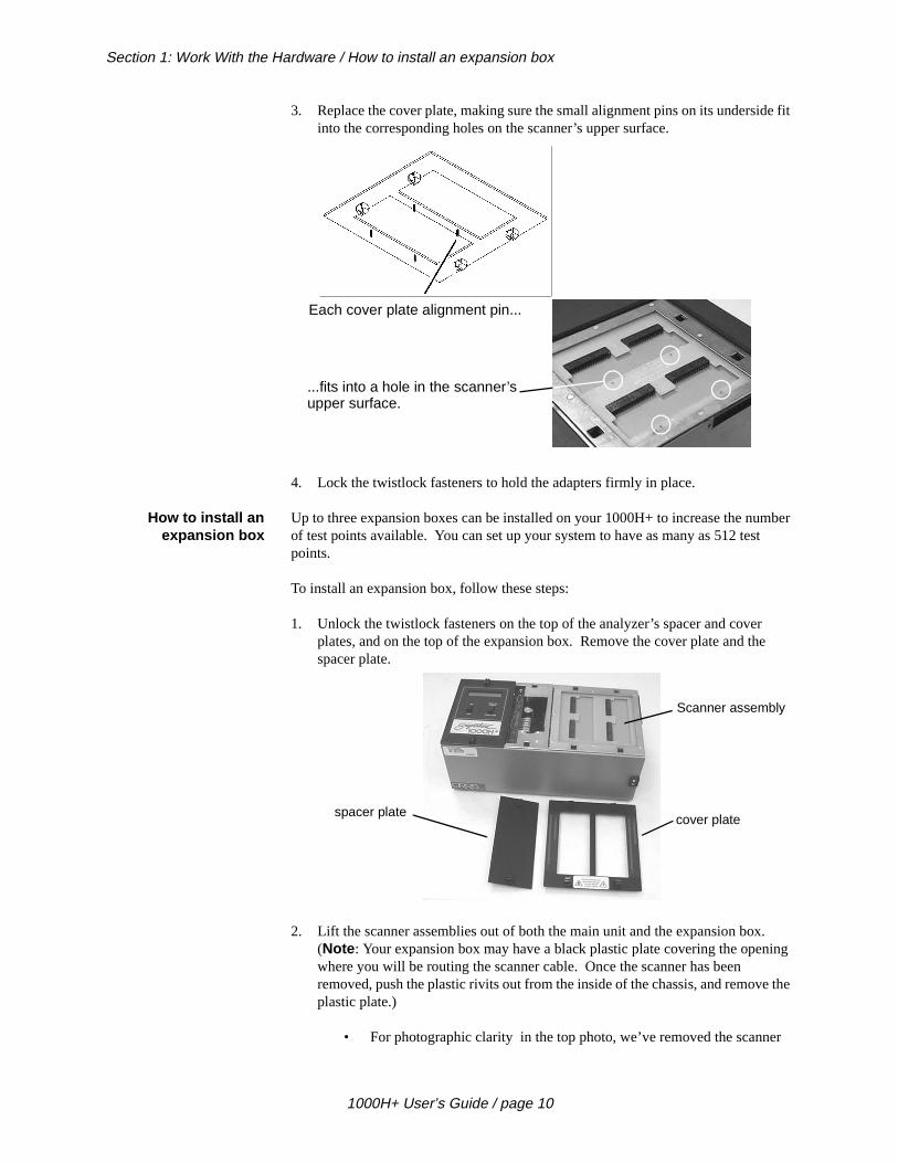
3. Replace the cover plate, making sure the small alignment pins on its undersiinto the corresponding holes on the scanner’s upper surface.
4. Lock the twistlock fasteners to hold the adapters firmly in place.
How to install anexpansion box
Up to three expansion boxes can be installed on your 1000H+ to increase the nuof test points available. You can set up your system to have as many as 512 tespoints.
To install an expansion box, follow these steps:
1. Unlock the twistlock fasteners on the top of the analyzer’s spacer and coverplates, and on the top of the expansion box. Remove the cover plate and thspacer plate.
2. Lift the scanner assemblies out of both the main unit and the expansion box(Note : Your expansion box may have a black plastic plate covering the openwhere you will be routing the scanner cable. Once the scanner has been removed, push the plastic rivits out from the inside of the chassis, and removplastic plate.)
• For photographic clarity in the top photo, we’ve removed the scann
Each cover plate alignment pin...
...fits into a hole in the scanner’supper surface.
spacer platecover plate
Scanner assembly
1000H+ User’s Guide / page 10

ec-tor see
assembly from the main unit, and disconnected it. You see the conntor that plugs into the main unit’s scanner assembly, and the connecthat plugs into the scanner assembly in the expansion box. You alsothe plastic plate in the main unit’s cable routing opening partially removed. You should remove the plate completely. Make sure the connections to both the main unit’s scanner and the scanner in the expansion box are secure.
.
Connector goes to mainscanner
Connector goes to expansion box scanner
Remove this plasticplate completely
This view shows the cables that connect the main unit to the expansion box as they should appear just before you plug them together. Be surethe connectors are well-seated, and that the connection is secure.
Gently lower both scanners into their boxes, routing the connectingcables through the openings in the side of each box.
1000H+ User’s Guide / page 11
Section 1: Work With the Hardware / How to install an expansion box
ox
he rely
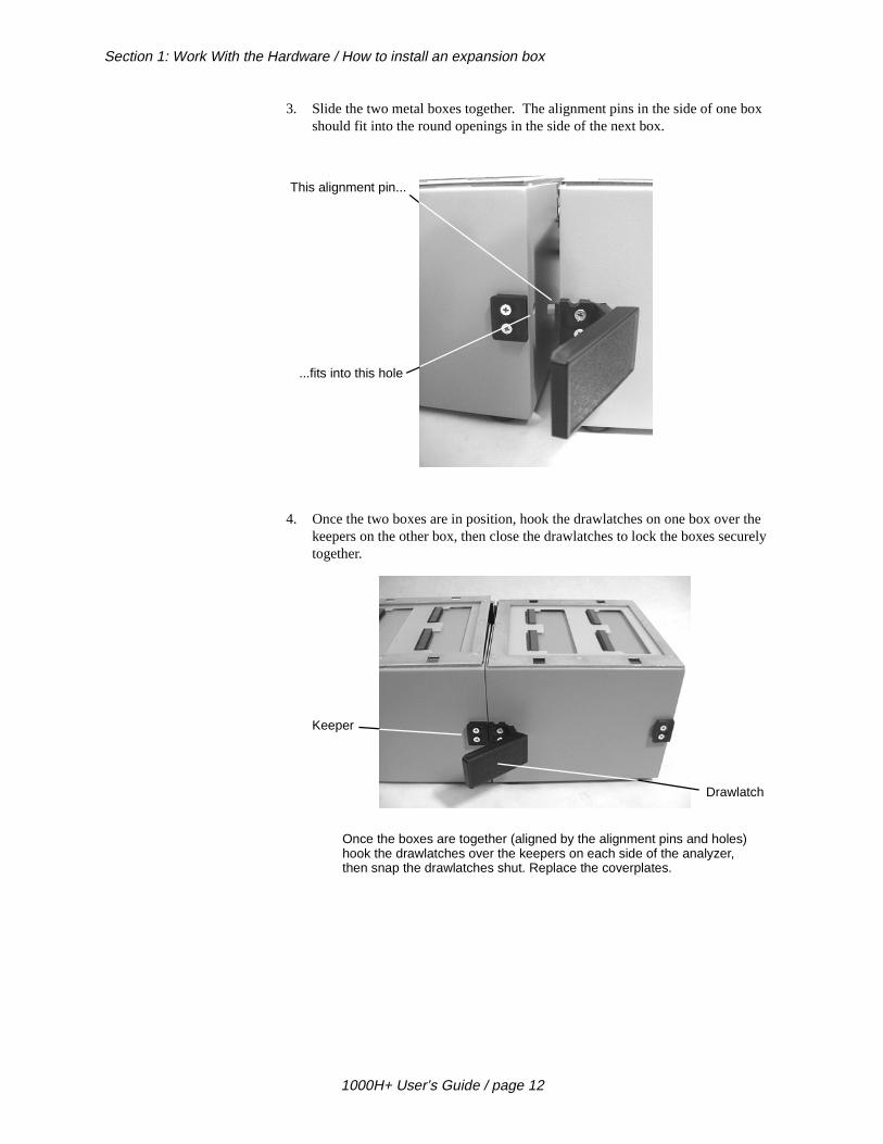
3. Slide the two metal boxes together. The alignment pins in the side of one bshould fit into the round openings in the side of the next box.
4. Once the two boxes are in position, hook the drawlatches on one box over tkeepers on the other box, then close the drawlatches to lock the boxes secutogether.
This alignment pin...
...fits into this hole
Once the boxes are together (aligned by the alignment pins and holes)hook the drawlatches over the keepers on each side of the analyzer, then snap the drawlatches shut. Replace the coverplates.
Keeper
Drawlatch
1000H+ User’s Guide / page 12

his,
wer
e
5. This photo shows your 1000H+ as it should look with one expansion box installed, and the spacer plate and coverplates in place..
How to change theEPROM
You may need to change the EPROM on the microprocessor assembly. To do tfollow these steps:
1. Disconnect the wall transformer from the wall outlet, then disconnect the pocable from the socket on the back of the analyzer.
2. Unlock the twistlock fasteners, remove the spacer plate, then gently raise thmicroprocessor assembly out of the box.
Disconnect the powercable
1000H+ User’s Guide / page 13
Section 1: Work With the Hardware / How to change the EPROM
the
et,
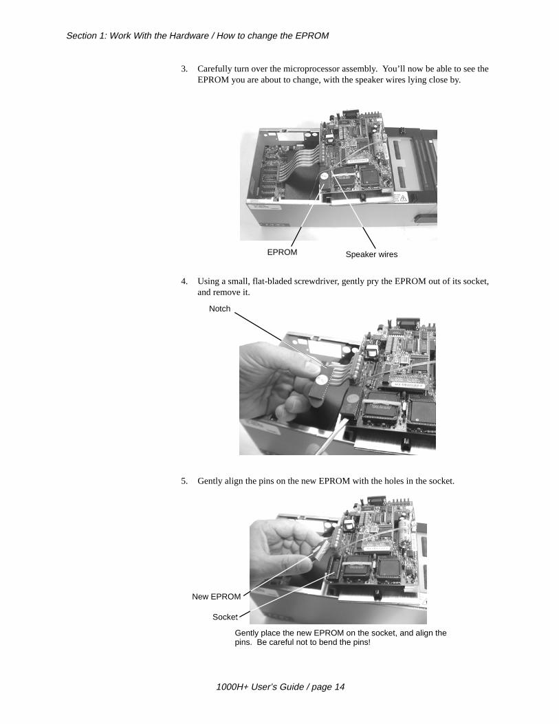
3. Carefully turn over the microprocessor assembly. You’ll now be able to seeEPROM you are about to change, with the speaker wires lying close by.
4. Using a small, flat-bladed screwdriver, gently pry the EPROM out of its sockand remove it.
5. Gently align the pins on the new EPROM with the holes in the socket.
EPROM Speaker wires
Notch
Gently place the new EPROM on the socket, and align thepins. Be careful not to bend the pins!
Socket
New EPROM
1000H+ User’s Guide / page 14

Be
pacer
l al ctory
he
. th a a
6. Carefully push the new EPROM down into the socket using even pressure. careful not to misalign or bend the pins!.
7. Gently lower the microprocessor assembly back into the box. Replace the splate, then lock the twistlock fasteners. Your unit is reassembled!
Adding a printer The 1000H+ works with almost any printer that has an Epson/Centronics paralleinterface. WARNING!! Connecting the analyzer to a printer with an RS-232 seriinterface will cause serious damage to the analyer, and is not covered by your fawarranty.
To connect the printer, use a standard Epson/Centronic parallel interface cable, readily available from almost any PC dealer. Plug one end of the cable into the printer, and the other end into the analyzer’s parallel printer socket as shown in tphoto.
How do I know if Ihave a parallel
printer?
To see if you have a parallel printer, look for the parallel connector on the printerPrinters usually have a parallel interface located in back. Many printers have boserial and a parallel connector. To work with the 1000H+ your printer must have36-position female ribbon connector similar to the one shown here.
Plug the printerin here
1000H+ User’s Guide / page 15

Section 1: Work With the Hardware / Can I use one printer with more than one analyzer?
ge h
ther
en-n, r-
so
he
Can I use one printerwith more than one
analyzer?
Yes. To use your printer with more than one analyzer, use a switchbox. To chanwhich analyzer the printer is receiving information from, simply change the switcsetting on the box.
How do I use a printerwithout an on-line/off-
line switch?
If your printer does not happen to have an on-line/off-line switch, you can use eiof two solutions:
• Add a switch by placing a switch in the wire to pin 11 of the Epson/Ctronics printer cable. When pin 11 on either side of the cable is opethe analyzer will see the printer as being off-line, and will display infomation rather than send it to the printer. When you close the switchthat pin 11 is closed, information will be sent to the printer.
• If you have a switch box available, you can connect the cable to theswitchbox, and use its switch as the on-line/off-line switch.
Changing thecompany name
To change the company name that appears in the documentation produced by t1000H+, you can order an EPROM change from Cirris Systems. Replace the EPROM. For details on how to do this, see page 13.
1000H+ User’s Guide / page 16

’ll
Section 2: Check the Option Settings
Overview: The Cirris 1000H+ has twelve test options. Before we learn a Sample Cable, wemake sure they are set to their factory defaults.
How to check theoption settings
To check the option settings, do these things:
1. Press in and hold the Display/Print switch as you turn on the analyzer by
pressing the On switch. Hold Display/Print until Ready To Set Up Options appears.
2. Once Ready To Set Up Options appears in the display, release Display/Print.
3. Select the Create Test From option by pressing Display/Print.
• If the setting is SAMPLE CABLE , go on to the next option by pressing Display/Print
• To change the option setting, press Function until SAMPLE CABLE
appears, then go on to the next option by pressing Display/Print.
Press and hold...
...then press here
SET UP OPTIONSREADY TO
Press to step
Press to changeoption settings
through options
1000H+ User’s Guide / page 17

Section 2: Check the Option Settings / What to do if you go past the value you want
old
e
urn .
4. Continue stepping through the options by pressing Display/Print, changing the
settings as necessary by pressing Function, until all the options are set as shownin this table: When you are done, Ready to Learn will appear on the display.
What to do if you gopast the value you
want
If you want to go backward through either the options or settings, press in and hthe Memory button on the back of the analyzer, while pressing Display/Print or
Function. Note : All options or settings will roll over to the beginning when you argoing forward or backward..
Your option settingsare saved
When you set the value you want, it is saved once it is displayed on the screen.Toff the analyzer, the analyzer will use those settings when you power it up again
Factory Default Option Settings
Option Setting
Create Test From SAMPLE CABLE
Connection Resistance AUTO
Hipot Voltage 300 V
Insulation Resistance 10 MΩ
Hipot Duration 100mS
Apply Hipot to ALL ADAPTER PINS
Single Net Error FAILS HIPOT
Auto Hipot OFF
Error Tones are LOW
Sorted Wire List is OFF
Count All Cables is OFF
Auto Print is OFF
Memory button
Touch 1 User’s Manual (1500-Volt System) / page 18
ting
last addi-
each pe y
, you initely
help
-
tically t d for
you asure
uld ing a
Section 3: What the Option Settings Mean
Overview The Cirris 1000H+ has twelve test option settings which you set to meet your tesrequirements. In this section, we’ll tell you what each of the settings means.
Create Test From Gives you the option to create a new test setup from a new Sample Cable, your test setup, or by learning a complex cable that contains resistors and/or diodes intion to ordinary wire connections.
SAMPLE CABLE : Use this setting to learn standard simple cables (cables that contain only wires and connectors).
LAST TEST SETUP : Use this setting when you need to use the same test setup time you turn on the analyzer. Useful when testing large batches of the same tycable. Will help protect your test setup from a power failure, or if you accidentallturn on the analyzer with an untested cable connected.
COMPLEX ASSEMBLY : Use this setting to learn a cable that contains resistorsdiodes, or divider networks in addition to ordinary wires and connectors. When use this setting, the Connection Resistance refers to the resistance level that defseparates wires from resistors. The analyzer sets this to 5 Ω. You may change the setting to meet your needs. Using the Connection Resistance CALC mode mayyou determine a good setting.
ConnectionResistance
Specifies the maximum resistance a connection can have and still be considered good. For example, if you set the Connection Resistance to 10 Ω, the analyzer will consider all connections with resistances less than 10 Ω as good, and those with resistances greater than 10 Ω as bad.
Range : 0.1 to 100 Ω, 500 Ω, 1MΩ, 5 MΩ, AUTO, CALC.
AUTO mode : When you set the Connection Resistance to AUTO, the 1000H+ measures the resistance of each connection in your Sample Cable, then automasets the Connection Resistance threshold to a value 20% higher than the largesresistance measured in the Sample Cable. The 20% margin of error is increaseresistances less than 1Ω.
CALC mode : Setting the Connection Resistance to CALC causes the 1000H+ to measure the resistance of the connections in the Sample Cable in the same waywould measure them with an ohmmeter. In this mode, the analyzer can only meresistances up to 10KΩ. After the analyzer calculates the resistance of the SampleCable, it prompts RESISTANCE READY. Press the Display/Print switch to display all resistances measured below 10Kohms.
Hipot Voltage Specifies what voltage will be applied during hipot testing, between pins that shonot be connected. This determines how effective the insulation on a cable is dur
1000H+ User’s Guide / page 19
Section 3: What the Option Settings Mean / Insulation Resistance with hipot off
lyzer an
bon
ce at
at
lts
Once
ins
test. The higher the voltage you set, the higher the insulation resistance the anacan detect. Voltage settings will affect the range of insulation resistance settingsavailable to you. Warning!! Do not subject cable assemblies to voltages higher ththey are designed to handle, because this may damage them. For example, ribcable is usually designed to handle up to 300 volts.
Insulation Resistancewith hipot off
By setting the Insulation Resistance threshold, you select the highest resistance that the analyzer will detect during a test. For example, setting the Insulation Resistan50KΩ means the analyzer will detect connections with resistances up to 50KΩ. Any connections with resistances higher than 50KΩ will be ignored. Important! The Insulation Resistance setting must be equal to or greater than the Connection Resistance setting. When you select a hipot voltage, the resistance is the level which a hipot failure will be detected.
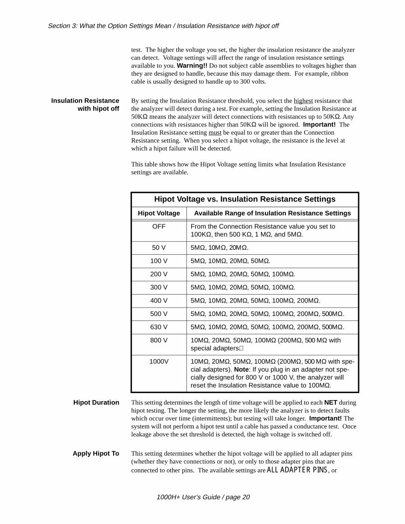
This table shows how the Hipot Voltage setting limits what Insulation Resistancesettings are available.
Hipot Duration This setting determines the length of time voltage will be applied to each NET during hipot testing. The longer the setting, the more likely the analyzer is to detect fauwhich occur over time (intermittents); but testing will take longer. Important! The system will not perform a hipot test until a cable has passed a conductance test. leakage above the set threshold is detected, the high voltage is switched off.
Apply Hipot To This setting determines whether the hipot voltage will be applied to all adapter p(whether they have connections or not), or only to those adapter pins that are connected to other pins. The available settings are ALL ADAPTER PINS, or
Hipot Voltage vs. Insulation Resistance Settings
Hipot Voltage Available Range of Insulation Resistance Settings
OFF From the Connection Resistance value you set to 100KΩ, then 500 KΩ, 1 MΩ, and 5MΩ.
50 V 5MΩ, 10ΜΩ, 20ΜΩ.
100 V 5MΩ, 10MΩ, 20MΩ, 50MΩ.
200 V 5MΩ, 10MΩ, 20MΩ, 50MΩ, 100MΩ.
300 V 5MΩ, 10MΩ, 20MΩ, 50MΩ, 100MΩ.
400 V 5MΩ, 10MΩ, 20MΩ, 50MΩ, 100MΩ, 200MΩ.
500 V 5MΩ, 10MΩ, 20MΩ, 50MΩ, 100MΩ, 200MΩ, 500MΩ.
630 V 5MΩ, 10MΩ, 20MΩ, 50MΩ, 100MΩ, 200MΩ, 500MΩ.
800 V 10MΩ, 20MΩ, 50MΩ, 100MΩ (200MΩ, 500 MΩ with special adapters).
1000V 10MΩ, 20MΩ, 50MΩ, 100MΩ (200MΩ, 500 MΩ with spe-cial adapters). Note : If you plug in an adapter not spe-cially designed for 800 V or 1000 V, the analyzer will reset the Insulation Resistance value to 100MΩ.
1000H+ User’s Guide / page 20
Section 3: What the Option Settings Mean / Single Net Error
uld to
this as
est)
allows
ple, t.
r
hich
CONNECTIONS ONLY. The CONNECTIONS ONLY setting is generally faster, since only connected pins will be hipot tested.
Single Net Error The range of settings for this option is IS IGNORED or FAILS HIPOT. This option allows cables with one oversized net, or a net with excessive capacitance (that wonormally fail) to pass a hipot test. Most of the time, a cable which has insulationresistance problems will show two or more net failures, since they will be leakingeach other.
Caution! When Apply Hipot To is set to Connections Only, and Single Net Error is set to Ignored, the analyzer will not report an error if one net is leaking to any unconnected pin in the adapter.
Auto Hipot This option lets you choose between automatic and manual hipot testing. Whenoption is ON, the analyzer will automatically begin a hipot test on a cable as soonthat cable passes a resistance test. You can repeat the hipot test by pressing theFunction switch.
When this option is OFF, a cable won’t be hipot tested (after passing a resistance t
until you press the Function switch.The Function switch becomes a “push-to-test” switch on the hipot test.
Error Tones When the analyzer detects errors, it emits a series of sharp beeps. This setting you to set the volume of these beeps. The available settings are Off, Low, and High.
Sorted Wire List When this option is ON, it changes the order that errors appear in a net. For exampin J1-01 will always come before pin J1-14 if they are connected in the same neWhen this option is OFF, the order that pins appear in a net is determined by the scanning order of the analyzer.
Count All Cables Once the analyzer is programmed, and you’ve begun testing cables, the analyzebegins to count the cables you test. When this option is ON, the printout from your tests shows the total number of cables tested, as well as the number of cables wtested as good. When this option is OFF, the printout will show only the number of cables that tested as good.
Auto Print When a printer is connected to the analyzer and this option is ON, the system will print a one-line report when each cable being tested is disconnected, indicating whether that cable tested as good, bad, or intermittent. When this option is OFF, the system will not print each result automatically.
1000H+ User’s Guide / page 21

Section 3: What the Option Settings Mean / Auto Print
1000H+ User’s Guide / page 22

elist
f the .You lists
is ng
n
ady
on
Section 4: Learn a Sample Cable, Store it in Memory
Overview: In this chapter, we will show you how to learn a Sample Cable, then store the wirfrom that cable in one of the analyzer’s permanent memory locations.
Memory in the 1000H+ The Signature 1000H+ has from 10 to 50 permanent memory locations you can storewirelists in. How many memory locations are available depends upon the size owirelists you want to save. Large wirelists take up more memory than small onescan store wirelists in these locations, retrieve wirelists from them, and delete wirefrom them. There is also one temporary memory location called “Last Learned.”
Last Learned When the analyzer learns a new Sample Cable, the wirelist data from that cablestored in the temporary “Last Learned” memory location. It stays there until youeither save it in one of the permanent memory locations, or overwrite it by learnianother Sample Cable.
Learn a Sample Cable Before you can learn a Sample Cable, you must install the right cable adapters oyour 1000H+ (see page 9 for instructions on how to do this).
To learn the Sample Cable do these things:
1. Connect the Sample Cable you want to learn to the connector adapters alreinstalled on the 1000H+. Turn on the analyzer by pressing the On switch. The analyzer will learn the cable, then prompt Please Verify .
2. To verify that the Sample Cable has been learned correctly, press Display/Print.
• If you have a printer connected to the analyzer, when you press Display/Print, the analyzer will print out the cable’s wirelist information. Theprintout is your cable documentation. Compare the printed informatito the Sample Cable’s specification sheet or build list to be sure the cable is a good one.
SIG:6BECB9-6F350PLEASE VERIFY
Turn the analyzer on
1000H+ User’s Guide / page 23
Section 4: Learn a Sample Cable, Store it in Memory / Store the Sample Cable in memory
.
go. a-
these
n. -
• If you don’t have a printer connected to the analyzer, pressing Display/Print causes the analyzer to prompt wirelist information in its display
Repeatedly press Display/Print to step through the wirelist, transcribingthe information to a blank documentation form (see page 79) as youCompare the transcribed information to the Sample Cable’s specifiction sheet or build list to be sure it’s a good cable.
3. Disconnect the Sample Cable from the analyzer.
Store the SampleCable in memory
Now that you’ve learned the Sample Cable, and verified that the wirelist data is correct, you may store the cable in the analyzer’s memory. To store the cable, dothings:
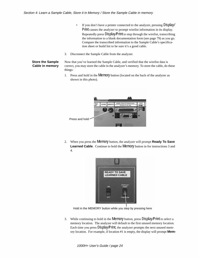
1. Press and hold in the Memory button (located on the back of the analyzer as shown in this photo).
2. When you press the Memory button, the analyzer will prompt Ready To Save Learned Cable . Continue to hold the Memory button in for instructions 3 and 4.
3. While continuing to hold in the Memory button, press Display/Print to select a memory location. The analyzer will default to the first unused memory locatioEach time you press Display/Print, the analyzer prompts the next unused memory location. For example, if location #1 is empty, the display will prompt Mem-
Press and hold
READY TO SAVELEARNED CABLE
Hold in the MEMORY button while you step by pressing here
1000H+ User’s Guide / page 24
Section 4: Learn a Sample Cable, Store it in Memory / What to do if you see an error message
te ’s
t
stance
ings
ory Location 1 Is Now Unused . Keep pressing Display/Print until you find the memory location you want. Note : If the display prompts No Memory Available , all of the analyzer’s memory locations are full. You’ll have to delea wirelist to make room available. See “To delete a cable from the analyzermemory, do these things:” on page 33 for instructions on how to do this.
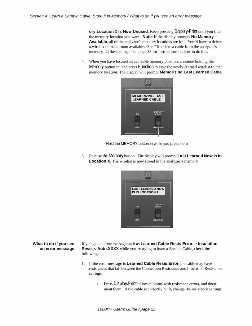
4. When you have located an available memory position, continue holding the Memory button in, and press Function to save the newly-learned wirelist to thamemory location. The display will prompt Memorizing Last Learned Cable .
5. Release the Memory button. The display will prompt Last Learned Now Is In Location X . The wirelist is now stored in the analyzer’s memory.
What to do if you seean error message
If you get an error message such as Learned Cable Resis Error or Insulation Resis < Auto.XXXX while you’re trying to learn a Sample Cable, check the following:
1. If the error message is Learned Cable Resis Error , the cable may have resistances that fall between the Connection Resistance and Insulation Resisettings.
• Press Display/Print to locate points with resistance errors, and docu-ment them. If the cable is correctly built, change the resistance sett
LEARNED CABLEMEMORIZING LAST
Hold the MEMORY button in while you press here
LAST LEARNED NOWIS IN LOCATION 1
1000H+ User’s Guide / page 25

Section 4: Learn a Sample Cable, Store it in Memory / What to do if you see an error message
se
not
e
an ee
to accomodate the cable. See “To check the option settings, do thethings:” on page 17 for details on how to do this.
• If the cable is not built correctly, use another Sample Cable that doescontain the errors, and repeat the learning process. Note : If you discon-nect the cable with the error, or if you press the Memory button, the analyzer will enter the test mode.
2. If the error message is Insulation Resis < Auto .XXXX , check to see if the Connection Resistance is set to AUTO, and the Auto resistance is higher than thInsulation Resistance setting.
• Change the Insulation Resistance setting to be equal to or higher ththe AUTO Connection Resistance setting prompted in the display. Spage 17 for details on how to change the setting.
1000H+ User’s Guide / page 26
d ed the the
t
ill
e
Section 5: Test Your First Cable
How to test your firstcable
Now that you have installed any expansion boxes you will be using, have installeyour connector adapters, have checked the option settings, and have programmanalyzer by learning a Sample Cable (see page 23), or by retrieving a cable fromanalyzer’s memory (see page 31), you are ready to test your first cable.
To test your first cable, follow these steps:
1. Disconnect and remove the Sample Cable from the analyzer.
2. Connect the cable you want to test to the analyzer.
• Once you have connected the cable, the analyzer will automaticallybegin the test. (Note : If you have set the Auto Hipot option to OFF, the analyzer will stop after the continuity and conductance tests, prompReady To Hipot , and wait for you to press Function to begin the hipot test.)
• WARNING!! Do not connect a powered (“live”) cable to the analyzer! This will seriously damage your analyzer, and will immediately void any stated or implied warranty.
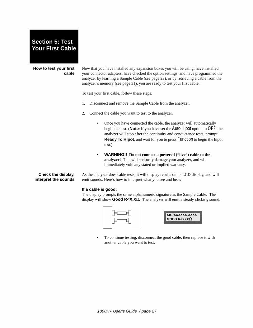
Check the display,interpret the sounds
As the analyzer does cable tests, it will display results on its LCD display, and wemit sounds. Here’s how to interpret what you see and hear:
If a cable is good:The display prompts the same alphanumeric signature as the Sample Cable. Thdisplay will show Good R<X.X Ω. The analyzer will emit a steady clicking sound.
• To continue testing, disconnect the good cable, then replace it with another cable you want to test.
SIG:XXXXXX-XXXXGOOD R<XXXΩ
1000H+ User’s Guide / page 27
Section 5: Test Your First Cable / Interpreting hipot test results
ting, f dou-
n set to
ay
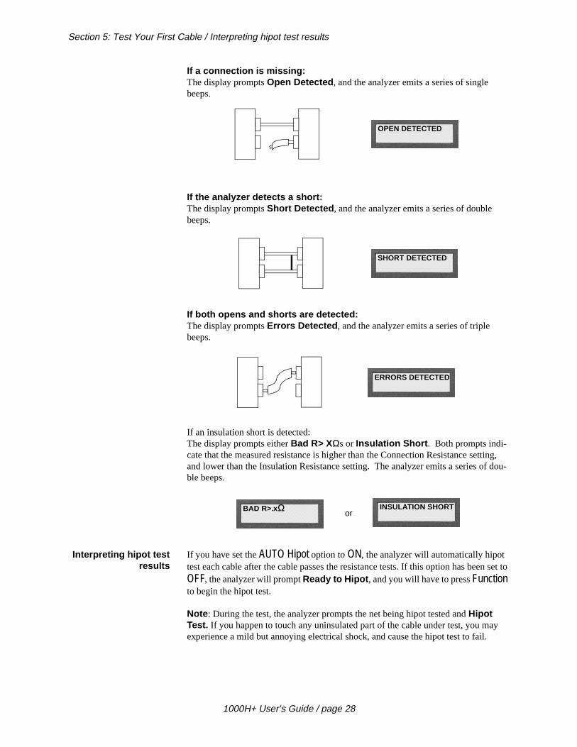
If a connection is missing:The display prompts Open Detected , and the analyzer emits a series of single beeps.
If the analyzer detects a short:The display prompts Short Detected , and the analyzer emits a series of double beeps.
If both opens and shorts are detected:The display prompts Errors Detected , and the analyzer emits a series of triple beeps.
If an insulation short is detected:The display prompts either Bad R> XΩs or Insulation Short . Both prompts indi-cate that the measured resistance is higher than the Connection Resistance setand lower than the Insulation Resistance setting. The analyzer emits a series oble beeps.
Interpreting hipot testresults
If you have set the AUTO Hipot option to ON, the analyzer will automatically hipot test each cable after the cable passes the resistance tests. If this option has beeOFF, the analyzer will prompt Ready to Hipot , and you will have to press Function to begin the hipot test.
Note : During the test, the analyzer prompts the net being hipot tested and Hipot Test. If you happen to touch any uninsulated part of the cable under test, you mexperience a mild but annoying electrical shock, and cause the hipot test to fail.
OPEN DETECTED
SHORT DETECTED
ERRORS DETECTED
BAD R>.x Ω
orINSULATION SHORT
1000H+ User’s Guide / page 28
Section 5: Test Your First Cable / Interpreting hipot test results
b-
r ome er-
the
e ill will
ts an le
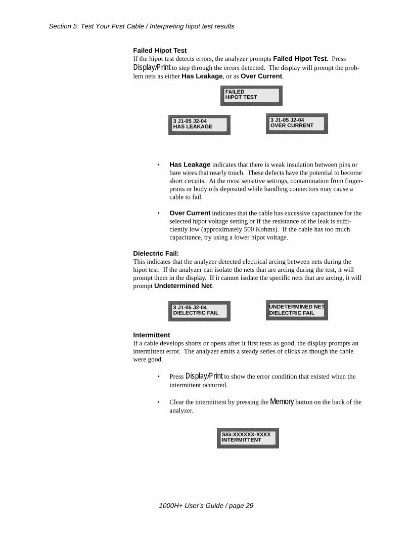
Failed Hipot TestIf the hipot test detects errors, the analyzer prompts Failed Hipot Test . Press Display/Print to step through the errors detected. The display will prompt the prolem nets as either Has Leakage , or as Over Current .
• Has Leakage indicates that there is weak insulation between pins obare wires that nearly touch. These defects have the potential to becshort circuits. At the most sensitive settings, contamination from fingprints or body oils deposited while handling connectors may cause acable to fail.
• Over Current indicates that the cable has excessive capacitance forselected hipot voltage setting or if the resistance of the leak is suffi-ciently low (approximately 500 Kohms). If the cable has too much capacitance, try using a lower hipot voltage.
Dielectric Fail:This indicates that the analyzer detected electrical arcing between nets during thhipot test. If the analyzer can isolate the nets that are arcing during the test, it wprompt them in the display. If it cannot isolate the specific nets that are arcing, itprompt Undetermined Net .
IntermittentIf a cable develops shorts or opens after it first tests as good, the display prompintermittent error. The analyzer emits a steady series of clicks as though the cabwere good.
• Press Display/Print to show the error condition that existed when the intermittent occurred.
• Clear the intermittent by pressing the Memory button on the back of the analyzer.
3 J1-05 J2-04
3 J1-05 J2-04
FAILED HIPOT TEST
HAS LEAKAGE OVER CURRENT
3 J1-05 J2-04
UNDETERMINED NET DIELECTRIC FAIL DIELECTRIC FAIL
SIG:XXXXXX-XXXX INTERMITTENT
1000H+ User’s Guide / page 29

Section 5: Test Your First Cable / Print or transcribe an error list
. To
this, a ou
Passed Hipot TestIf the hipot test is successful, the analyzer briefly prompts Passed Hipot Test , then cycles to a continuous resistance test and prompts Good R<.X Ω. The analyzer emits a steady clicking sound after each newly-completed continuity/conductance testrepeat the hipot test, press Function again. The conductance test always follows a successful hipot test, and continues until you remove the cable.
Print or transcribe anerror list
If the analyzer detects errors, it can prompt where the error is in a cable. To do press Display/Print while the cable is still connected to the analyzer. If you have printer connected to your analyzer, it will automatically print out an error list. If ydon’t have a printer, keep pressing Display/Print to step through the errors as you transcribe them to a cable documentation form (see page 79).
PASSED HIPOT TEST
SIG:BBF038-6J0A0 GOOD R<.XΩ
1000H+ User’s Guide / page 30
r the time e u
lyzer,
ting,
e
he
you
Section 6: Retrieve a Cable from Memory
Why retrieve a cable? Before the 1000H+ can test cables, it has to be programmed with wirelist data focables you intend to test. You can avoid having to re-learn a Sample Cable eachyou want to test, by storing the learned information in the analyzer’s memory (sepage 24 for instructions on how to do this). Once the information is stored, all yohave to do to set up for testing is to install the correct cable adapters on the anathen retrieve the cable data from memory in order to program the analyzer.
How to retrieve a cable To retrieve a learned cable’s data from memory and program the analyzer for tesdo these things:
1. Install the connector adapters that mate with the cables you want to test (sepage 9 for instructions on how to do this).
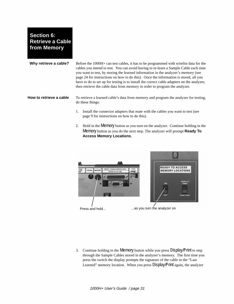
2. Hold in the Memory button as you turn on the analyzer. Continue holding in t
Memory button as you do the next step. The analyzer will prompt Ready To Access Memory Locations .
3. Continue holding in the Memory button while you press Display/Print to step through the Sample Cables stored in the analyzer’s memory. The first time press the switch the display prompts the signature of the cable in the “Last Learned” memory location. When you press Display/Print again, the analyzer
READY TO ACCESSMEMORY LOCATIONS
Press and hold... ...as you turn the analyzer on
1000H+ User’s Guide / page 31

Section 6: Retrieve a Cable from Memory / How to retrieve a cable
mber
t,
eady
’ve
d
prompts the signature for the cable stored in permanent memory location nu1 (there can be as many as 50 of these). Continue pressing Display/Print until you see the signature for the kind of cable you want to test.
4. When the display prompts the signature for the kind of cable you want to tesrelease the Memory button.
• If the display prompts Ready To Test , the analyzer has retrieved the Sample Cable data, the correct adapters are in place, and you are rto test cables.
• If the display prompts JX Adapter Sig: Should Be , this means that the adapters you have installed don’t go with the Sample Cable youretrieved. Read the display to get the correct adapters and their positions, then install them. Note : It’s OK to install adapters without turning off the analyzer when it is in this mode. Once you’ve installethe correct adapters, the display will prompt Ready To Test .
MEM LOCATION XSIG:XXXXXX-XXXX
Continue to hold... ...while you step through the cable signatures
READY TO TESTSIG:BBF038-0501
J1 ADAPTER SIG:SHOULD BE ACEFA1
C able re trieved, adapters a recorrect. You are ready to test.
Installed adapters are not correct.Install correct adapters. Whenyou’ve done that, prompt willchange to Ready to Test .
1000H+ User’s Guide / page 32

g ze of ou you
he
to
be d
Section 7: Delete a Cable from Memory
Why delete a cable? The Cirris 1000H+ has a maximum of 50 permanent memory locations for storincable information. How many locations are actually available depends on the sithe wirelists being stored. Small wirelists take up less space than large ones. Ymay need to delete cables to make room for new wirelists, or to discard wirelistsno longer use for testing.
How to delete a cable To delete a cable from the analyzer’s memory, do these things:
1. Hold in the Memory button as you turn on the analyzer. Continue holding in tbutton as you do the next step. The analyzer will prompt Ready To Access Memory Locations .
2. Continue holding in the Memory button while you press Display/Print to step through the Sample Cables stored in the analyzer’s memory, until you comethe signature of the cable you want to delete. (Remember, the first cable displayed will be the cable in the “Last Learned” memory location. It cannotdeleted.) When you come to the cable you want to delete, the display shoulprompt Mem. Location X Sig: XXXXXX-XXXX , indicating the memory location and signature of the cable.
READY TO ACCESSMEMORY LOCATIONS
Press and hold... ...as you turn the analyzer on
MEM LOCATION XSIG:XXXXXX-XXXX
Continue to hold...
1000H+ User’s Guide / page 33

Section 7: Delete a Cable from Memory / How to delete a cable
3. Continue to hold in the Memory button while you press Function to select the
cable for deletion. Continue to hold down the Function switch as you do the next step.
4. Delete the Sample Cable you’ve selected by first releasing the Memory button,
then releasing the Function switch. When you release the Memory button, the prompt will change to Mem Location X Is Now Unused . When you release the Function switch, the prompt will change to Ready To Learn . The memory location is now empty.
MEM LOCATION XIS TO BE DELETED
Continue to hold...
...while you press here to select the cable for deletion
MEM LOCATION XIS NOW UNUSED
First release this button...
...then release this button
1000H+ User’s Guide / page 34
ows the mem-r
o
.
Section 8: Print a Directory of Cables Stored in Memory
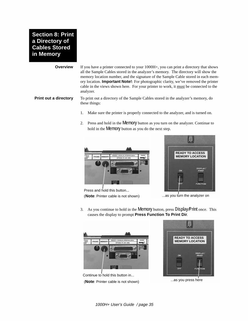
Overview If you have a printer connected to your 1000H+, you can print a directory that shall the Sample Cables stored in the analyzer’s memory. The directory will show memory location number, and the signature of the Sample Cable stored in eachory location. Important Note! : For photographic clarity, we’ve removed the printecable in the views shown here. For your printer to work, it must be connected to the analyzer.
Print out a directory To print out a directory of the Sample Cables stored in the analyzer’s memory, dthese things:
1. Make sure the printer is properly connected to the analyzer, and is turned on
2. Press and hold in the Memory button as you turn on the analyzer. Continue to
hold in the Memory button as you do the next step.
3. As you continue to hold in the Memory button, press Display/Print once. This causes the display to prompt Press Function To Print Dir .
READY TO ACCESSMEMORY LOCATION
...as you turn the analyzer onPress and hold this button...
(Note : Printer cable is not shown)
READY TO ACCESSMEMORY LOCATION
...as you press hereContinue to hold this button in...
(Note : Printer cable is not shown)
1000H+ User’s Guide / page 35
Section 8: Print a Directory of Cables Stored in Memory / Print out a directory
on-
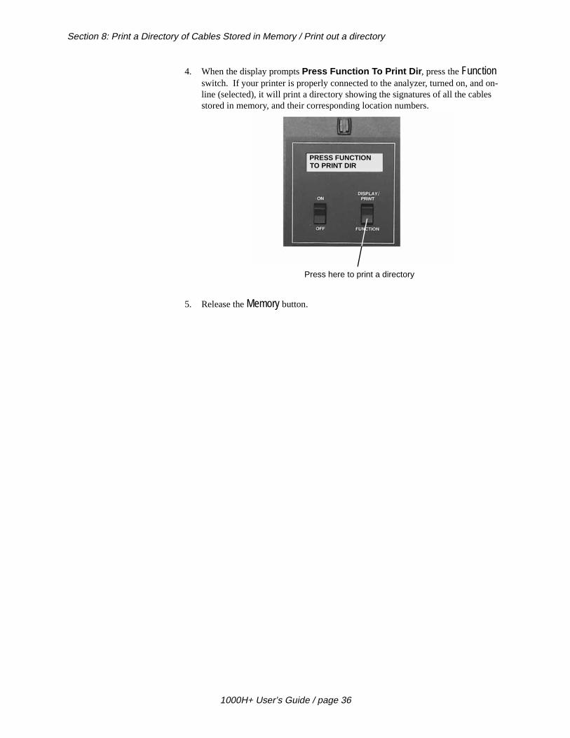
4. When the display prompts Press Function To Print Dir , press the Function switch. If your printer is properly connected to the analyzer, turned on, and line (selected), it will print a directory showing the signatures of all the cablesstored in memory, and their corresponding location numbers.
5. Release the Memory button.
PRESS FUNCTIONTO PRINT DIR
Press here to print a directory
1000H+ User’s Guide / page 36
lp you
ation nta-r tran-ave
n’t ture cu--
anu-ation to
Section 9: Cable Documentation and Signatures
What is cabledocumentation?
Cable documentation is a printed record of a Sample Cable’s unique signature, theadapters used to test it, and the test parameters used to test it. It also contains acomplete list of the interconnections in the cable, and any notes necessary to hebuild the cable.
Why prepare cabledocumentation?
When you prepare complete documentation, you prepare a standard set of informfrom which future cables will be built. The 1000H+ can help you prepare documetion by learning a Sample Cable. Once the cable has been learned, you can eithescribe it by hand onto a documentation form (see page 79), or print it out if you ha printer connected to your analyzer.Once the cable has been completely documented and stored in memory, you woneed to keep an array of “known good” cables handy for comparison. If the signaprompted by the analyzer after each test matches the signature in the cable’s domentation, you can be sure the cable is correctly built according to your specifications.
You can store Sample Cable information in the analyzer’s memory. When you retrieve that information from memory, you program the analyzer just as if you’d learned a real Sample Cable. The analyzer will prompt the Sample Cable’s alphmeric signature, and which connector adapters to install. See page 24 for informon how to store a Sample Cable in memory, and page 31 for information on howretrieve a cable from memory.
Please see next page...
1000H+ User’s Guide / page 37
Section 9: Cable Documentation and Signatures / How to interpret cable documentation
eed able
ture pted
tance ne me.
r the n J2
tion is
d are
How to interpret cabledocumentation
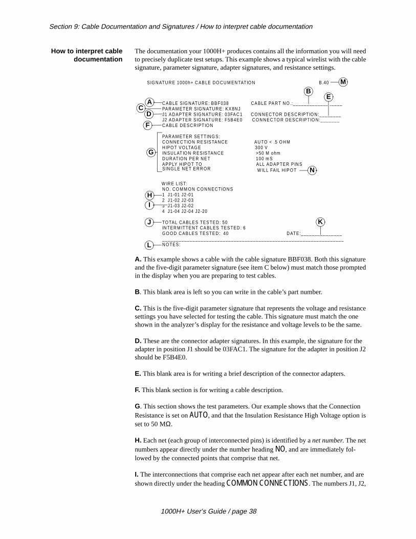
The documentation your 1000H+ produces contains all the information you will nto precisely duplicate test setups. This example shows a typical wirelist with the csignature, parameter signature, adapter signatures, and resistance settings.
A. This example shows a cable with the cable signature BBF038. Both this signaand the five-digit parameter signature (see item C below) must match those promin the display when you are preparing to test cables.
B. This blank area is left so you can write in the cable’s part number.
C. This is the five-digit parameter signature that represents the voltage and resissettings you have selected for testing the cable. This signature must match the oshown in the analyzer’s display for the resistance and voltage levels to be the sa
D. These are the connector adapter signatures. In this example, the signature foadapter in position J1 should be 03FAC1. The signature for the adapter in positioshould be F5B4E0.
E. This blank area is for writing a brief description of the connector adapters.
F. This blank section is for writing a cable description.
G. This section shows the test parameters. Our example shows that the ConnecResistance is set on AUTO, and that the Insulation Resistance High Voltage optionset to 50 MΩ.
H. Each net (each group of interconnected pins) is identified by a net number. The net numbers appear directly under the number heading NO, and are immediately fol-lowed by the connected points that comprise that net.
I. The interconnections that comprise each net appear after each net number, anshown directly under the heading COMMON CONNECTIONS. The numbers J1, J2,
C AB LE S IG N ATU R E: BB F038 CA BLE PA RT N O .:__________________PAR A M E TER S IG N ATU R E: KX 8N JJ1 AD APTER S IG NATU R E: 03FA C 1 C O N N EC TO R D ES C RIPTIO N :________J2 AD APTER S IG NATU R E: F5B4E 0 C O N N EC TO R D ES CR IPT IO N:_______ C AB LE DE SC R IPTIO N
PAR A M E TER SE TTING S:C O N NE C TIO N R E SISTA NC E AU TO < .5 O H MH IPO T V O LTAG E 300 VIN SU LAT IO N R ES ISTAN C E >50 M ohmD UR ATIO N PE R NE T 100 m SAP PLY H IP O T TO ALL AD APTER P IN S
N O . CO M M O N C O N N EC TIO N S1 J1-01 J2-012 J1-02 J2-033 J1-03 J2-024 J1-04 J2-04 J2-20
TO TAL CA BLE S TES TED : 50IN TER M ITTE N T CA BLES TES TED : 6G O O D C AB LES TE STE D : 40 D ATE:_________________________________________________________________________________N O TES :
A
BE
K
CD
F
G
HI
J
L
SIG N ATU R E 1000h+ C AB LE DO CU M EN TATIO N B .40 M
W ILL FA IL H IP O TS ING LE NE T ER R O R
W IR E L IST:
N
1000H+ User’s Guide / page 38

Section 9: Cable Documentation and Signatures / How signatures work
cific
sted as ad. the
-
s a a
e doc-
e in
ted ilt.
e of the nique se.
re,
rent
que,
J3, and J4 indicate the adapter position. The number after the hyphen is the spepin to which a connection is madeJ. Our example shows that a total of 50 cables has been tested. Forty of these tegood. Six cables tested as having intermittent errors, and four tested simply as bThis breakdown of good and bad cables appears on the documentation becauseanalyzer’s Count All Cables option was set to ON. When this option is set to OFF, the printout shows only the number of cables which tested as good.
K. This blank area is for writing in the date of the test.
L. This is a section left open for writing in any additional notes. You may wish to include a drawing of the cable here.
M. This shows the EPROM revision number your analyzer is equipped with.
N. “Will Fail Hipot” may or may not appear in the printout depending on what settings you are using.
How signatures work Signatures are the working basis of the 1000H+ system. When the 1000H+ learnSample Cable (a cable that you know is built correctly), it computes and displayscable signature for that Sample Cable. This signature becomes part of your cablumentation for that kind of cable.
• When the signature prompted by the analyzer matches the signaturyour cable documentation, you know that your test setup is correct.
• When the signature of a cable you are testing matches the documensignature during a test, you know the cable under test is correctly bu
Types of signatures The 1000H+ uses three types of signatures:
1. The cable signature.
2. The parameter signature.
3. The connector adapter signature(s).
The cable signatureThe first six characters in a signature (as displayed by the 1000H+) are called thcable signature. This six-character alphanumeric number represents a summary interconnections in a cable. When the analyzer learns a cable, it computes this usignature based on the cable’s interconnections, and the connector adapters in u
The parameter signatureWhen the 1000H+ displays a signature, it first displays the six-digit cable signatuthen a hyphen. The five-digit alphanumeric number that follows the hyphen is theparameter signature. It represents the voltage and resistance settings you have selected. Note : If you select the same voltage and resistance settings for two diffekinds of cables, both kinds will have the same parameter signature, but different cable signatures.
The connector adapter signature(s)The connector adapters you use to connect your cables to the 1000H+ have uni
1000H+ User’s Guide / page 39

Section 9: Cable Documentation and Signatures / How connector adapters are supported
ter ne. tation ur
stems terior rame
py
y
six-character connector adapter signatures. Each kind of adapter has its own adapsignature. These signatures help you verify that your test setups are correctly doThey appear on the labels attached to the adapters, and on your cable documen(see item D on page 39). When the adapter signatures match those found on yocable documentation, you have installed the correct adapters.
How connectoradapters are
supported
The 1000H+ uses connector adapters mounted on small printed circuit boards toconnect the cables you want to test to the analyzer’s scanner assembly. Cirris Sycan provide adapters for nearly all popular connectors. You can also make an exadapter cable to adapt to any connector with up to 120 pins by using an optional fmount stand. This photo shows a frame stand with D-sub type connectors.
Types of adapters There are three general adapter types available for the 1000H+. These are:
1. Single-high adapters. These are for connectors with up to 28 pins. They occuone “J” position on the analyzer’s scanner.
2. Double-high adapters. These are for connectors with from 29 to 64 pins. Theoccupy two “J” positions on the analyzer’s scanner.
.
Example: An ADBP-15 single-high adapter
Single-high adapter mounted inscanner position J1.
Example: ADPG-37 double-highadapter
Double-high adapter mounted inscanner postions J1, J2
1000H+ User’s Guide / page 40

Section 9: Cable Documentation and Signatures / How connector adapters are placed on the analyzer
py t one
ssem-le
bly. ay
he h J12,
3. Quad-high adapters. These are for connectors with up to 120 pins. They occufour “J” positions on the analyzer’s scanner. To use more than one of these atime, you must use an expansion box.
How connectoradapters are placed
on the analyzer
The 1000H+ analyzer itself has four connector adapter positions on its scanner ably, marked J1 through J4. Each position has 32 points, for a total of 128 availabpoints.
How connectoradapters are placedon expansion boxes
Each expansion box has four connector adapter positions on its scanner assemThese positions are not marked. They each have a white square on which you mwrite in the adapter position number. The analyzer recognizes the positions for tfirst expansion box as J5 through J8, for the second expansion box as J9 througand for the third expansion box as J13 through J16. You can connect up to threeexpansion boxes to the analyzer’s main box, for a total of 16 connector adapter positions (512 available test points).
Example: AD5P-100A quad-highadapter
Quad-high adapter mounted in scannerpositions J1, J2, J3, J4
J1
J2
J3
J4
Expansion box w ith white squares ata ll four adapter positions
Squares
1000H+ with 1 expansion boxinstalled. Eight “J” positions(256 test points) are available.
1000H+ User’s Guide / page 41
Section 9: Cable Documentation and Signatures / Order of adapter positions
rder n-to, itions
e, the nta-
w-ns
ector n ner
d
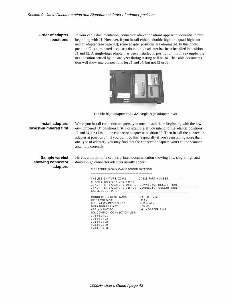
Order of adapterpositions
In your cable documentation, connector adapter positions appear in sequential obeginning with J1. However, if you install either a double-high or a quad-high conector adapter (see page 40), some adapter positions are eliminated. In this phoposition J2 is eliminated because a double-high adapter has been installed in posJ1 and J2. A single-high adapter has been installed in position J4. In this examplnext position sensed by the analyzer during testing will be J4. The cable documetion will show interconnections for J1 and J4, but not J2 or J3.
Install adapterslowest-numbered first
When you install connector adapters, you must install them beginning with the loest-numbered “J” positions first. For example, if you intend to use adapter positioJ2 and J4, first install the connector adapter at position J2. Then install the connadapter at position J4. If you don’t do this (especially if you’re installing more thaone type of adapter), you may find that the connector adapters won’t fit the scanassembly correctly.
Sample wirelistshowing connector
adapters
Here is a portion of a cable’s printed documentation showing how single-high andouble-high connector adapters usually appear.
Double-high adapter in J1-J2, single-high adapter in J4
SIG N ATU RE 1000H+ C ABLE DO CU M EN TATIO N________________________________________
CA BLE S IG N ATUR E : Z06A1 C AB LE PART N UM BE R :____________PAR AM ETE R S IG N ATU RE : 6J0A 0J1-AD A PTER S IG NATU R E: D 507F1 C O N N EC TO R D ES CR IPTIO N_______________J4-AD A PTER S IG NATU R E: 03FA C 1 CO NN E CTO R D E SC R IPTIO N _______________CA BLE D E SC R IPTIO N :____________________________________________
CO NN E CTIO N R ES ISTAN C E <A U TO .5 ohmHIP O T VO LTA G E 300 VIN S ULATIO N R ES ISTAN C E > 10 M ohmDU R ATIO N PE R N E T 100 M SAPP LY H IP O T TO A LL AD A PTER P IN SNO . C O M M O N C O N N EC TIO N LIS T:1 J1-01 J4-012 J1-02 J4-023 J1-04 J4-084 J1-05 J4-095 J1-03 J4-03
1000H+ User’s Guide / page 42
re:
ese
just
Section 10: Select a Test Procedure
Types of Tests Types of TestsUsing the Cirris 1000H+, you can perform three different kinds of tests. These a
1. Simple tests.
2. Complex tests.
3. Hipot tests.
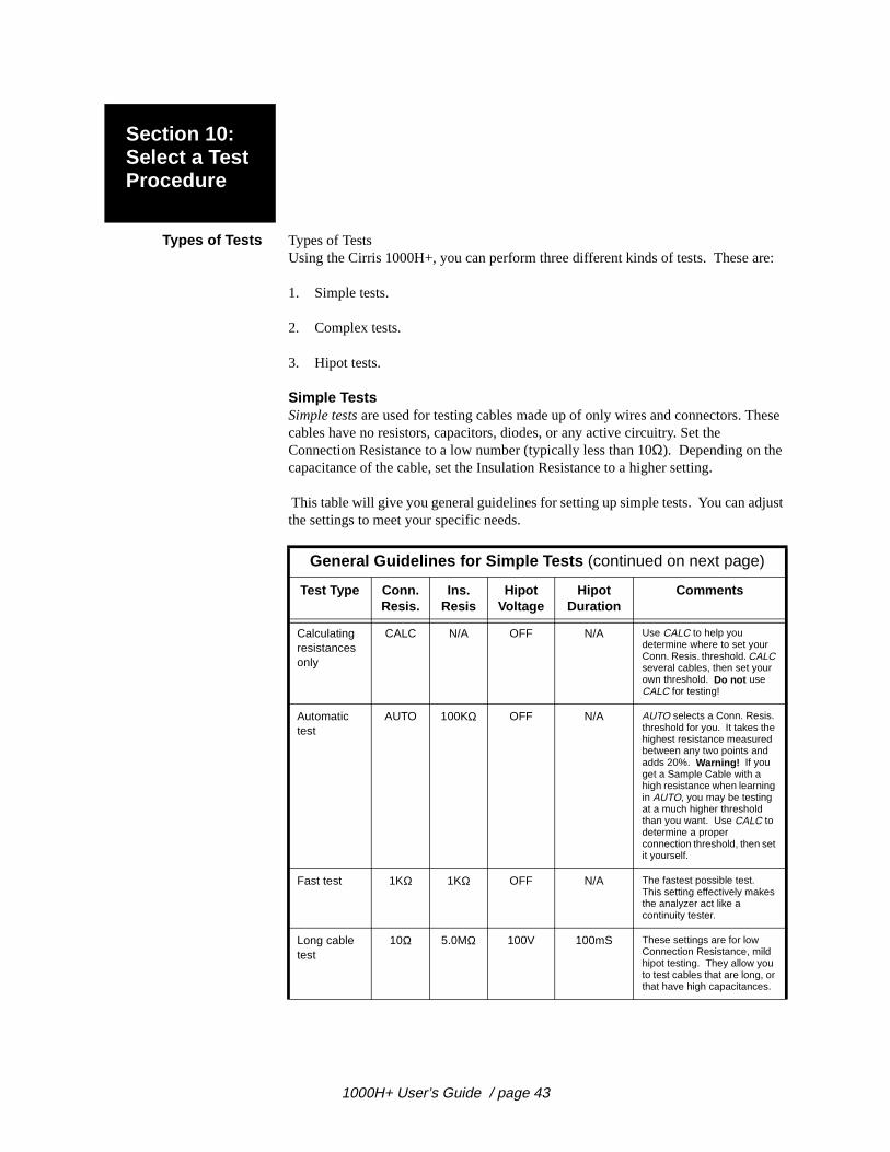
Simple TestsSimple tests are used for testing cables made up of only wires and connectors. Thcables have no resistors, capacitors, diodes, or any active circuitry. Set the Connection Resistance to a low number (typically less than 10Ω). Depending on the capacitance of the cable, set the Insulation Resistance to a higher setting.
This table will give you general guidelines for setting up simple tests. You can adthe settings to meet your specific needs.
General Guidelines for Simple Tests (continued on next page)
Test Type Conn. Resis.
Ins. Resis
Hipot Voltage
Hipot Duration
Comments
Calculating resistances only
CALC N/A OFF N/A Use CALC to help you determine where to set your Conn. Resis. threshold. CALC several cables, then set your own threshold. Do not use CALC for testing!
Automatic test
AUTO 100KΩ OFF N/A AUTO selects a Conn. Resis. threshold for you. It takes the highest resistance measured between any two points and adds 20%. Warning! If you get a Sample Cable with a high resistance when learning in AUTO, you may be testing at a much higher threshold than you want. Use CALC to determine a proper connection threshold, then set it yourself.
Fast test 1KΩ 1KΩ OFF N/A The fastest possible test. This setting effectively makes the analyzer act like a continuity tester.
Long cable test
10Ω 5.0MΩ 100V 100mS These settings are for low Connection Resistance, mild hipot testing. They allow you to test cables that are long, or that have high capacitances.
1000H+ User’s Guide / page 43
Section 10: Select a Test Procedure / Types of Tests
or :
.
epa-tance
u are
gs:
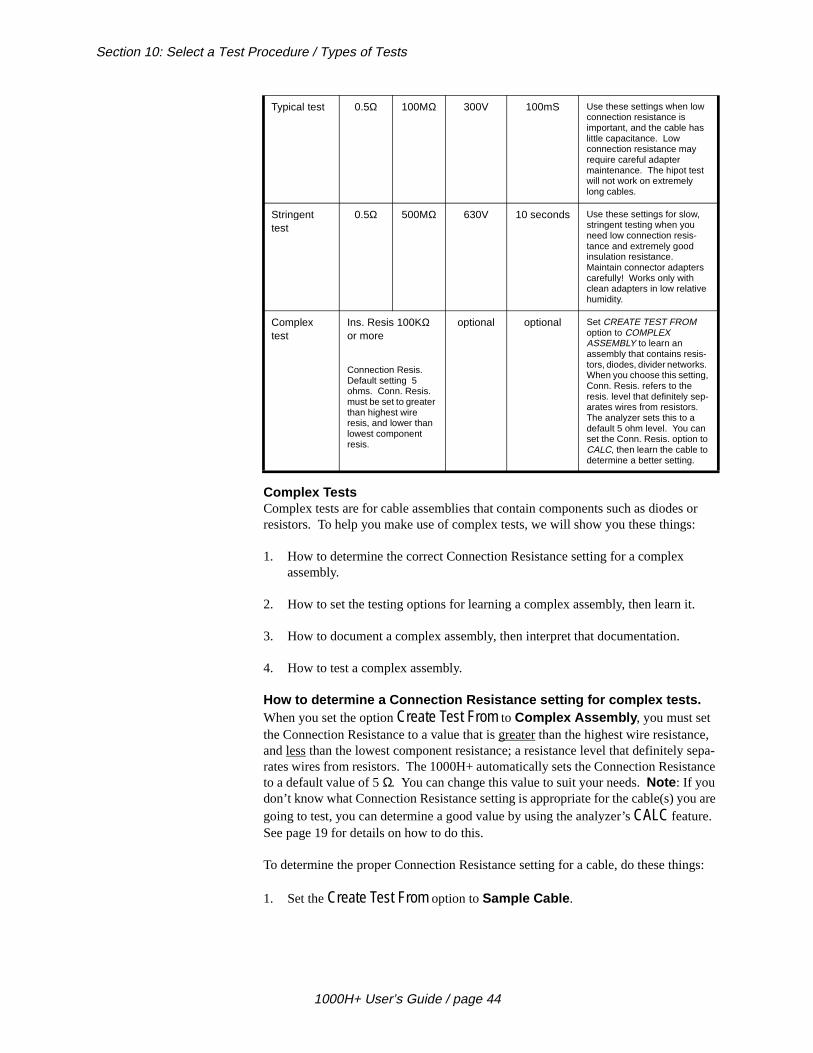
Complex TestsComplex tests are for cable assemblies that contain components such as diodesresistors. To help you make use of complex tests, we will show you these things
1. How to determine the correct Connection Resistance setting for a complex assembly.
2. How to set the testing options for learning a complex assembly, then learn it
3. How to document a complex assembly, then interpret that documentation.
4. How to test a complex assembly.
How to determine a Connection Resistance setting for complex tests.When you set the option Create Test From to Complex Assembly , you must set the Connection Resistance to a value that is greater than the highest wire resistance, and less than the lowest component resistance; a resistance level that definitely srates wires from resistors. The 1000H+ automatically sets the Connection Resisto a default value of 5 Ω. You can change this value to suit your needs. Note : If you don’t know what Connection Resistance setting is appropriate for the cable(s) yogoing to test, you can determine a good value by using the analyzer’s CALC feature. See page 19 for details on how to do this.
To determine the proper Connection Resistance setting for a cable, do these thin
1. Set the Create Test From option to Sample Cable .
Typical test 0.5Ω 100MΩ 300V 100mS Use these settings when low connection resistance is important, and the cable has little capacitance. Low connection resistance may require careful adapter maintenance. The hipot test will not work on extremely long cables.
Stringent test
0.5Ω 500MΩ 630V 10 seconds Use these settings for slow, stringent testing when you need low connection resis-tance and extremely good insulation resistance. Maintain connector adapters carefully! Works only with clean adapters in low relative humidity.
Complex test
Ins. Resis 100KΩ or more
Connection Resis.Default setting 5 ohms. Conn. Resis. must be set to greater than highest wire resis, and lower than lowest component resis.
optional optional Set CREATE TEST FROM option to COMPLEX ASSEMBLY to learn an assembly that contains resis-tors, diodes, divider networks. When you choose this setting, Conn. Resis. refers to the resis. level that definitely sep-arates wires from resistors. The analyzer sets this to a default 5 ohm level. You can set the Conn. Resis. option to CALC, then learn the cable to determine a better setting.
1000H+ User’s Guide / page 44

Section 10: Select a Test Procedure / Types of Tests
2. Set the Connection Resistance setting to CALC .
3. Turn on the analyzer, and learn the cable.
4. When the display prompts Please Verify , press the Memory button on the back of the analyzer. The prompt will change to Resistance Ready .
5. When the prompt changes to Resistance Ready , press Display/Print. A list of the measured resistances in the cable will be printed.
6. From your printout locate these resistances:
• The highest measured resistance for nets that you know contain onlywires.
CREATE TEST FROMSAMPLE CABLE
CONNECTION RESISCALC
SIG:XXXXXX-XXXXPLEASE VERIFY
Press herePress here
SIG:XXXXXX-XXXXRESISTANCE READY
SIG:XXXXXX-XXXXRESISTANCE READY
Press here
1000H+ User’s Guide / page 45
Section 10: Select a Test Procedure / Types of Tests
n in has a of .1 n m to
in
,
iate ire
arn to
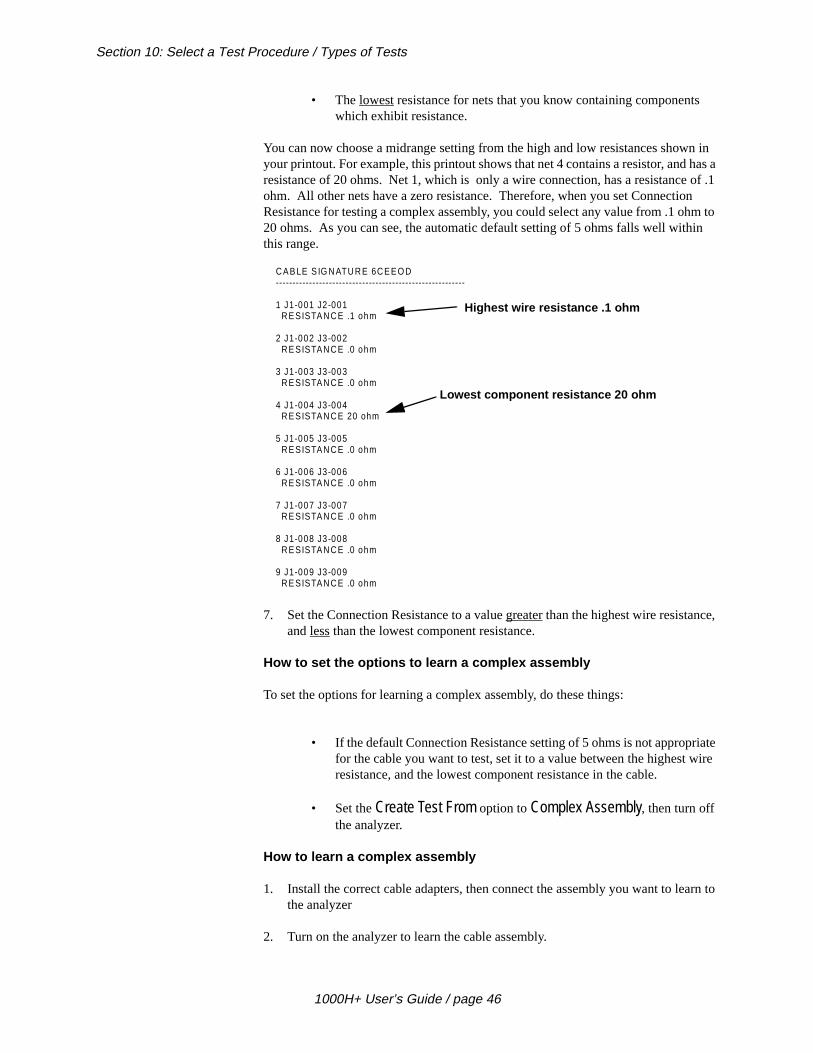
• The lowest resistance for nets that you know containing componentswhich exhibit resistance.
You can now choose a midrange setting from the high and low resistances showyour printout. For example, this printout shows that net 4 contains a resistor, and resistance of 20 ohms. Net 1, which is only a wire connection, has a resistanceohm. All other nets have a zero resistance. Therefore, when you set ConnectioResistance for testing a complex assembly, you could select any value from .1 oh20 ohms. As you can see, the automatic default setting of 5 ohms falls well withthis range.
7. Set the Connection Resistance to a value greater than the highest wire resistanceand less than the lowest component resistance.
How to set the options to learn a complex assembly
To set the options for learning a complex assembly, do these things:
• If the default Connection Resistance setting of 5 ohms is not approprfor the cable you want to test, set it to a value between the highest wresistance, and the lowest component resistance in the cable.
• Set the Create Test From option to Complex Assembly, then turn off the analyzer.
How to learn a complex assembly
1. Install the correct cable adapters, then connect the assembly you want to lethe analyzer
2. Turn on the analyzer to learn the cable assembly.
C A B LE S IG N ATU R E 6C E E O D---------------------------------------------------------
1 J1-001 J2-001 R E SISTA N C E .1 ohm
2 J1-002 J3-002 R E SISTA N C E .0 ohm
3 J1-003 J3-003 R E SISTA N C E .0 ohm
4 J1-004 J3-004 R E SISTA N C E 20 ohm
5 J1-005 J3-005 R E SISTA N C E .0 ohm
6 J1-006 J3-006 R E SISTA N C E .0 ohm
7 J1-007 J3-007 R E SISTA N C E .0 ohm
8 J1-008 J3-008 R E SISTA N C E .0 ohm
9 J1-009 J3-009 R E SISTA N C E .0 ohm
Highest wire resistance .1 ohm
Lowest component resistance 20 ohm
1000H+ User’s Guide / page 46
Section 10: Select a Test Procedure / Types of Tests
s a is uld
The analyzer first prompts Learning Cable , as it learns all interconnections in the cable which have resistances up to the Insulation Resistance setting you have selected.
The prompt changes to Learning Complex as the analyzer learns the pattern of wires which have resistances less than the Connection Resistance setting.
The prompt finally changes to Creating Checks as the analzyer learns the resistorand diodes in the cable. The analyzer sets the accuracy of the resistor check todefault value of 10%. You can change this value using CTL or CTLynx from CirrSystems. Important! If you change this value, the analyzer’s accuracy (4%) shoalways be added to the expected accuracy of the resistance.
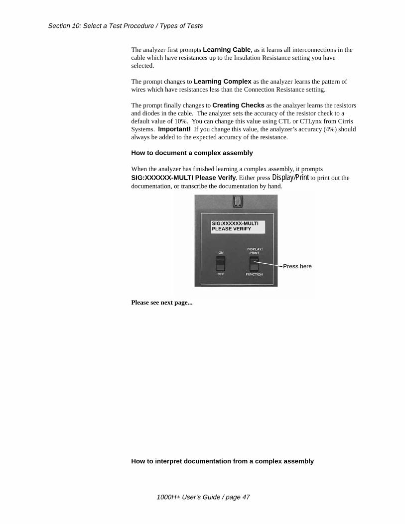
How to document a complex assembly
When the analyzer has finished learning a complex assembly, it prompts SIG:XXXXXX-MULTI Please Verify . Either press Display/Print to print out the documentation, or transcribe the documentation by hand.
Please see next page...
How to interpret documentation from a complex assembly
SIG:XXXXXX-MULTIPLEASE VERIFY
Press here
1000H+ User’s Guide / page 47
Section 10: Select a Test Procedure / Types of Tests
with
insula-
est.
is
spec-
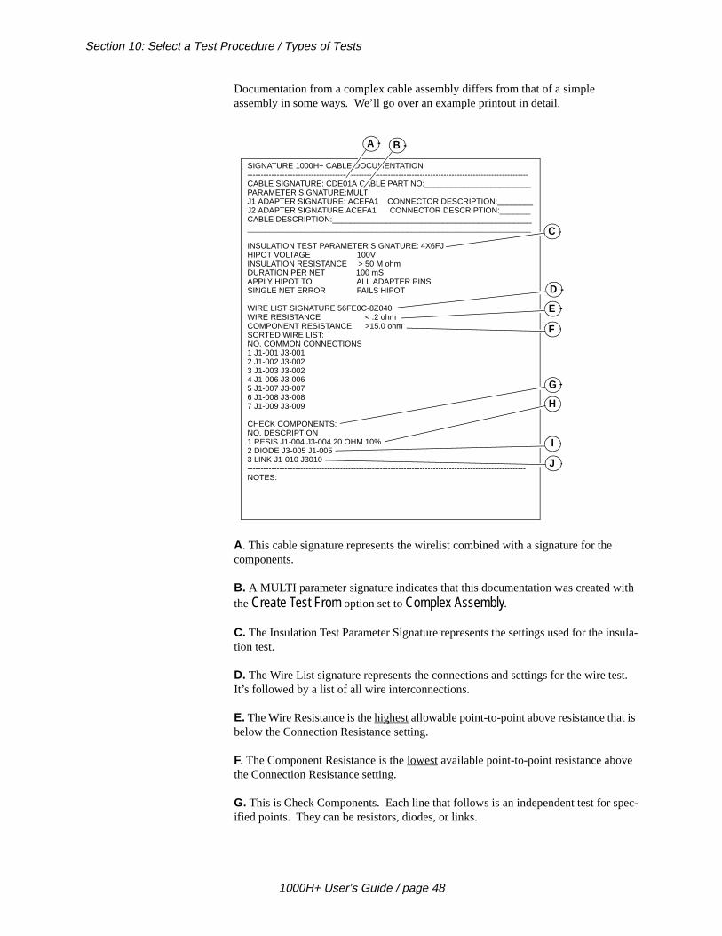
Documentation from a complex cable assembly differs from that of a simple assembly in some ways. We’ll go over an example printout in detail.
A. This cable signature represents the wirelist combined with a signature for thecomponents.
B. A MULTI parameter signature indicates that this documentation was created the Create Test From option set to Complex Assembly.
C. The Insulation Test Parameter Signature represents the settings used for the tion test.
D. The Wire List signature represents the connections and settings for the wire tIt’s followed by a list of all wire interconnections.
E. The Wire Resistance is the highest allowable point-to-point above resistance that below the Connection Resistance setting.
F. The Component Resistance is the lowest available point-to-point resistance abovethe Connection Resistance setting.
G. This is Check Components. Each line that follows is an independent test for ified points. They can be resistors, diodes, or links.
SIGNATURE 1000H+ CABLE DOCUMENTATION----------------------------------------------------------------------------------------------------------CABLE SIGNATURE: CDE01A CABLE PART NO:________________________PARAMETER SIGNATURE:MULTIJ1 ADAPTER SIGNATURE: ACEFA1 CONNECTOR DESCRIPTION:________J2 ADAPTER SIGNATURE ACEFA1 CONNECTOR DESCRIPTION:_______CABLE DESCRIPTION:_____________________________________________________________________________________________________________
INSULATION TEST PARAMETER SIGNATURE: 4X6FJHIPOT VOLTAGE 100VINSULATION RESISTANCE > 50 M ohmDURATION PER NET 100 mSAPPLY HIPOT TO ALL ADAPTER PINSSINGLE NET ERROR FAILS HIPOT
WIRE LIST SIGNATURE 56FE0C-8Z040WIRE RESISTANCE < .2 ohmCOMPONENT RESISTANCE >15.0 ohmSORTED WIRE LIST:NO. COMMON CONNECTIONS1 J1-001 J3-0012 J1-002 J3-0023 J1-003 J3-0024 J1-006 J3-0065 J1-007 J3-0076 J1-008 J3-0087 J1-009 J3-009
CHECK COMPONENTS:NO. DESCRIPTION1 RESIS J1-004 J3-004 20 OHM 10%2 DIODE J3-005 J1-0053 LINK J1-010 J3010
---------------------------------------------------------------------------------------------------------NOTES:
A B
C
D
E
F
G
H
I
J
1000H+ User’s Guide / page 48

Section 10: Select a Test Procedure / First pass of a complex test
sis-04. If tside
J3-
, but nce is
he
nnect t to
not
f ters
using .
er
s
g the
H. This indicates that a resistor is present in the cable. It shows two points, a retance, and a percentage. The resistance is measured between J1-003 and J1-0the measured resistance is more than 22 ohms, or less than 18 ohms, it falls outhe specified 10% tolerance for the resistor, and the analyzer reports an error.
I. This line indicates that a diode is present in the cable. It is connected between005 (the anode), and J12-005 (the cathode).
J. This shows two points that were somehow linked in the learned Sample Cablea specific test was not created for them. This occurs when the Insulation Resistaset higher than 100KΩ, and a connection exists between 100KΩ and the Insulation Resistance. It also occurs in a cable with a complex system of resistors which tanalyzer cannot completely unscramble on its own.
How to test a complex cable assembly
To test a complex cable assembly, do these things:
1. Set the test options (see page 17 for instructions on how to do this), then coa Sample Cable (a cable that you know is built correctly) of the kind you wantest, to the analyzer.
2. Learn and document the Sample Cable.
3. Disconnect the Sample Cable, then connect a cable that you want to test.
First pass of acomplex test
Insulation TestFirst, the analyzer does a low voltage insulation test to verify that points which aresupposed to be connected are in fact, not connected.
• If you have set a hipot voltage, this test is supplementary to the hipottest that will be conducted later. It is used to find gross errors.
• If you have not set a hipot voltage, this test is the insulation portion othe complex test, and the analyzer will use the insulation test parameyou’ve set.
Wires TestSecond, the analyzer does a wires test (checking connections without resistors)the wirelist test parameters. If it detects an error, the analyzer loops on this test
Check Components TestThird, the analyzer tests individual components. If it detects an error, the analyzloops on that specific check.
• If the analyzer detects an error during any of these three tests, presDisplay/Print to print out an error list.
• If the analyzer detects no errors, it will continuously loop on the firstthree tests until you disconnect the cable.
Hipot TestIf you have set a hipot voltage, and the analyzer does not detect any errors durin
1000H+ User’s Guide / page 49

Section 10: Select a Test Procedure / Limitations when testing complex assemblies
the are too
e enta-
or n the
sis- as t pass
previous tests, it will prompt Ready To Hipot .
• If the Auto Hipot option is set to ON, the analyzer will automatically perform a hipot test after the cable has passed all other tests.
• If the Auto Hipot option is set to OFF, the analyzer will prompt Ready to Hipot . You must press Function to begin a hipot test.
Limitations whentesting complex
assemblies
When you test complex assemblies, remember these things:
1. Any connections which have resistances between the Wire Resistance and Component Resistance are seen by the analyzer as errors. The resistanceslow to be seen as components, and too high to be seen as wires.
2. The connection pattern for test points which have resistances below the WirResistance must match the wire connections specified in the cable’s documtion.
3. All points in a cable assembly that are not connected by either components wires must be insulated from each other by resistances which are greater thaInsulation Resistance setting.
4. All connections which have resistances that fall between the Component Retance setting and the Insulation Resistance setting are seen by the analyzercomponents. They must have a corresponding Component Check, and musthe test for that check.
1000H+ User’s Guide / page 50

Section 10: Select a Test Procedure / Hipot Testing
le elec-.
ion ons in g the
e ana-ins .
That refully
ff the
e ana-n
Hipot Testing The purpose of hipot testing is to test the effectiveness of the insulation on a cabassembly.When you hipot test, you are making sure that there is extremely hightrical resistance between points that should not be connected in the cable or harness
Important note! Before the analyzer performs a hipot test, it performs a connectresistance test (sometimes called a continuity test) to make sure that all connectithe cable are correct. If the analyzer finds any open or shorted connections durincontinuity test, it will not perform the hipot test.
Once a cable passes the continuity test, the analyzer can begin a hipot test. Thlyzer applies high voltage to a group of connected pins (“nets”). The remaining pare tied together. In the example below, we see net number 1 being hipot tested
Remember that each net the analyzer tests has capacitance to every other net. means there is a current surge as this capacitance is charged. The analyzer camonitors this current surge. The amount of current tells the analyzer how much energy is being delivered to the cable. If the current delivered is excessive, the amount of energy delivered might be dangerous; therefore, the analyzer shuts ohigh voltage and fails that net, labeling it “Over Current”
If the current surge subsides to an acceptable level, the hipot test continues. Thlyzer has already calculated the maximum amount of current it will allow based othe Insulation Resistance and Hipot Voltage option settings you’ve chosen (see
1234
1234NC
1234
1234NC
OPEN
This is a known-good cablewith all connections intact.
Example of the same cablewith an open connection.The hipot test cannot be doneon this cable.
1234
1234NC
+-
I
Hipot voltage
Current meter
Time
Current
Maximum allowablecurrent
Hipot Duration
Overcurrent error
1000H+ User’s Guide / page 51

Section 10: Select a Test Procedure / Tips on selecting Hipot Voltage settings
to tays
st. If and
er
a
ge to
ort
uture n ost .
ns) t if ther.
page 20). The current flow is monitored during the hipot duration you have set, make sure it does not exceed the maximum allowed current. If the current flow sbelow the maximum allowed current for the hipot duration, the net passes the teit does not stay below the maximum allowed current, the net fails the hipot test, the analyzer labels it “Has Leakage.” Note : The analyzer does not check where the current flows; it only knows that too much current is leaving the high voltage powsupply.
If the current flow spikes above the maximum allowable current during the hipot duration, the analyzer shuts off the high voltage, and labels the cable as having dielectric failure.
Tips on selectingHipot Voltage settings
Remember, when you select a hipot voltage, you are setting the amount of voltabe applied between pins that are not connected. Remember these things when you select hipot voltage settings:
• The more voltage you use, the more likely the analyzer is to detect contamination between pins, or frayed wires that almost create a shcircuit. However, higher test voltages only work well on cables with little pin-to-pin capacitance.
• Higher voltage settings require greater pin-to-pin spacing on cable connectors.
• Subjecting a cable assembly to excessive voltage may degrade its fperformance. Use the lowest voltage setting that still finds insulatioproblems in a cable. Most cables require no more than 630 volts. Mribbon cables are designed to handle a maximum of about 300 volts
• The hipot test applies high voltage to a net (a group of connected piand measures the current that flows from the net. The analyzer does no determine which net or pin the current is flowing to. This means thatseveral nets have leakage, you cannot tell which nets leak to each o
Time
Current
Maximum allowablecurrent
Hipot Duration
“Has Leakage” error
Time
Current
Maximum allowablecurrent
Hipot Duration
Dielectric Failure
1000H+ User’s Guide / page 52
Section 10: Select a Test Procedure / Hipot voltage and capacitance problems
re s to likely
volt-.
the
a ests ed
g the
mber
e . ss
y go-
the
Hipot voltage andcapacitance problems
Excessive capacitance in a cable assembly is a major consideration when you adeciding on what Hipot Voltage, Hipot Duration, and Insulation Resistance settinguse. If a cable has shielding or a grounded net, capacitance problems are more to occur. Remember these things:
• In general, the higher the capacitance a cable has, the lower a hipotage setting you’ll be able to use. See page 20 for further information
• If you find that a cable has excessive capacitance, first try lowering Hipot Voltage setting. You may also set the Single Net Error option to
Is Ignored. This will cause the analyzer to ignore a single-net hipot failure. (A single-net hipot failure is an indication of the presence ofnet with high capacitance, a net with too many points, or a net that tas borderline.) Normally, hipot failures show up with at least two failnets.
• If you’ve set the Apply Hipot option to Connections Only, the analyzer will not detect leakage of a single net to any unconnected pins.
Tips on selectingInsulation Resistance
settings
Remember, when you select an Insulation Resistance setting, you are specifyinlowest resistance that should appear between unconnected points. See page 20 for more information on Insulation Resistance versus Hipot Voltage settings. Remethese things:
• Using the highest setting might increase your chances of finding somkinds of errors. You might not want to use an extremely high settingOil, solder flux, or fingerprints left over from the manufacturing procecan become conductive in high relative humidity conditions.
• If you are testing in relative humidity conditions above 75%, you mahave more failures when you test at 500 megohms, or even 200 mehms.
• In general, select an Insulation Resistance setting that is lower thanresistance of normal contamination on the cable.
1000H+ User’s Guide / page 53

Section 10: Select a Test Procedure / Tips on selecting Insulation Resistance settings
1000H+ User’s Guide / page 54
H+.
r pin 1,
Section 11: Rework and Guided Assembly
The hand-held testprobe
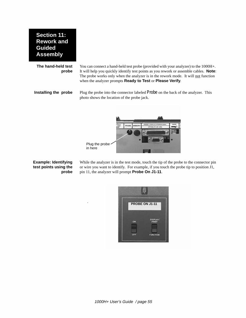
You can connect a hand-held test probe (provided with your analyzer) to the 1000It will help you quickly identify test points as you rework or assemble cables. Note : The probe works only when the analyzer is in the rework mode. It will not function when the analyzer prompts Ready to Test or Please Verify .
Installing the probe Plug the probe into the connector labeled Probe on the back of the analyzer. This photo shows the location of the probe jack.
Example: Identifyingtest points using the
probe
While the analyzer is in the test mode, touch the tip of the probe to the connectoor wire you want to identify. For example, if you touch the probe tip to position Jpin 11, the analyzer will prompt Probe On J1-11 .
Plug the probein here
PROBE ON J1-11.
1000H+ User’s Guide / page 55

Section 11: Rework and Guided Assembly / Displaying multiple interconnected pins
pins he
open. ce the the
Displaying multipleinterconnected pins
Up to three different pins can be displayed at the same time. If more than three are interconnected, a plus sign (+) will appear in the lower right-hand corner of tdisplay. To view any additional interconnections, press Display/Print.
Using the probe toidentify an open
circuit
Using the probe, the analyzer can detect which end of an interconnection has an When the analyzer prompts an open, use the sharp metal tip of the probe to pierinsulation of the wire that should connect between the two pins. The pin shown indisplay is the pin that has a good connection to the wire. The pin that is not displayed is the open.
Reworkinstructions
Before you begin reworking a cable assembly, remember these things:
• If you have a printer connected to your analyzer, either turn it off or disconnect it.
• When the analyzer displays errors, pressing Display/Print once will put
the analyzer into rework mode. If you press Display/Print twice, the analyzer will just prompt all the errors it detects.
Please see next page...
PROBE ON J1-09J1-10 J1-11 +
Plus sign here indicatesmore than three pointsare interconnected.
Press to displayadditional points
PROBE ON J3-02
J1-01
J3-02
Open
1000H+ User’s Guide / page 56
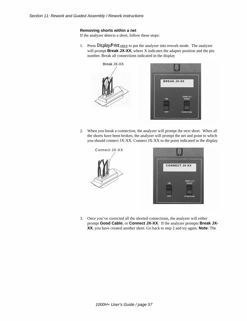
Section 11: Rework and Guided Assembly / Rework instructions
n all hich lay.
Removing shorts within a netIf the analyzer detects a short, follow these steps:
1. Press Display/Print once to put the analyzer into rework mode. The analyzer will prompt Break JX-XX , where X indicates the adapter position and the pinnumber. Break all connections indicated in the display
2. When you break a connection, the analyzer will prompt the next short. Whethe shorts have been broken, the analyzer will prompt the net and point to wyou should connect JX-XX. Connect JX-XX to the point indicated in the disp
3. Once you’ve corrected all the shorted connections, the analyzer will either prompt Good Cable , or Connect JX-XX . If the analyzer prompts Break JX-XX, you have created another short. Go back to step 2 and try again. Note : The
BREAK JX-XX
Break JX-XX
CONNECT JX-XX
Connect JX -XX
1000H+ User’s Guide / page 57

Section 11: Rework and Guided Assembly / Removing shorts between nets
s
ll tell
analyzer may prompt Intermittents as you rework the connection. To clear thiprompt, press the Memory button on the back of the analyzer.
Removing shortsbetween nets
If the analyzer detects short circuits in the cable or harness you are testing, it wiyou where to make cuts to correct the shorts. This will happen if two nets should become shorted. To correct a detected short, do these things:
1. The analyzer will prompt Cut JX-XX From JX-XX , where X indicates the adapter positions and pin number.
2. Locate the short between the nets, and remove it.
Please see next page...
GOOD CABLE BREAK JX-XX
Cable has been corrected You’ve created another short.G o back and try aga in
CUT JX-XXFROM JX-XX
1000H+ User’s Guide / page 58

Section 11: Rework and Guided Assembly / Correcting opens
pt
e
.
ple
le
n.
f you
Correcting opens If the analyzer prompts Connect JX-XX to JX-XX indicates that the cable you’re testing has an open circuit. To correct an open, follow these steps:
1. Locate the open circuit prompted in the analyzer’s display.
2. Make the correct connections in the cable as indicated.
• Once you’ve connected all the opens, the analyzer should prompt Good Cable .
• If you should happen to create another short, the analyzer will promBreak JX-XX .
GuidedAssembly
Building cables pin-to-pinTo use guided assembly to build pin-to-pin cables, follow these steps:
1. Following the documentation for the kind of cable you want to build, install thcorrect connector adapters onto the 1000H+, then replace the cover plate.
2. Either connect a Sample Cable of the kind you want to build, or retrieve the correct wirelist from memory (see page 31 for instructions on how to do this)If you use a retrieved wirelist, skip step 3, and go directly to step 4.
3. Turn on the analyzer and learn the Sample Cable, then disconnect the SamCable.
4. Install the same kinds of connectors used in the Sample Cable onto the cabadapters already installed in the analyzer.
5. Make the first connection in your cable that is specified in the documentatioThe analyzer should prompt Open Detected .
• If the analyzer prompts Errors Detected , you have not connected twopoints that should be connected; you have created a short instead. Ihave created a short, break it, and go back to make the first good connection.
6. Once the analyzer prompts Open Detected , press Display/Print once. The analyzer will prompt you with the next set of points you should connect.
CONNECT JX-XXTO JX-XX
1000H+ User’s Guide / page 59
Section 11: Rework and Guided Assembly / Guided Assembly
s
reate
e
, or s
ple
er on
le
yzer
ak pts
ding
7. Connect the next set of points prompted by the analyzer. If the connection icorrect, the analyzer willdisplay Attach JX-XX to JX-XX .
8. Repeat the last step by connecting the next set of points prompted. If you ca short, the analyzer will prompt Break JX-XX.
9. Continue connecting points as prompted by the 1000H+ until the analyzer prompts Good Cable or Ready To Hipot . This indicates you have finished wiring the assembly.
Building cables that have one end terminated with a connectorTo build cables that have only one end terminated, follow these steps:
1. Following the documentation for the kind of cable you want to build, install thright cable adapters onto the analyzer, and replace the cover plate.
2. Either connect a Sample Cable of the kind you want to build to the analyzerretrieve the wirelist for the kind of cable you want to build from the analyzer’memory (see page 31 for instructions on how to do this). If you use a wirelist retrieved from memory, skip step 3 and go directly to step 4.
3. Turn on the analyzer and learn the Sample Cable, then disconnect the SamCable.
4. Insert the connector on the terminated end of the cable into the cable adaptthe analyzer.
5. Insert an empty connector of the type correct for the cable into the other cabadapter on the analyzer.
6. Plug the probe into the Probe jack on the back of the analyzer.
7. Make the first connection specified in your cable’s documentation. The analshould prompt Open Detected .
• If the analyzer prompts Errors Detected , you have created a short instead of connecting the two points that should be connected. Brethe short, check your build list, and try again until the analyzer promOpen Detected .
8. Press Display/Print to enter rework mode.
9. Probe the loose end of one of the wires. The display will prompt Probe On JX-XXX. Connect this wire to the appropriate pin on the empty connector, accorto your cable documentation.
10. If you create an error, the display will read Break JX-XXX . Remove the error, then try reconnecting the loose wire at the correct position.
11. Continue until the display reads either Good Cable , or Ready to Hipot .
1000H+ User’s Guide / page 60

ou m is Cirris
Section 12: Troubleshooting
What is in thissection?
In this section we will tell you how to deal with three basic kinds of trouble whichmay occur when you are working with your 1000H+. These are:
• Error messages as prompted by the analyzer in its display.
• General problems with the analyzer.
• Problems with printing.
Need more help? Callus!
Each section will help you solve problems you might have with your analyzer. Ymay be able to correct some of the problems yourself. If you find that the problea defective microprocessor or scanner assembly, or if for some other reason youcannot solve the problem yourself, please contact our customer support team at by calling 1-801-973-4600, or 1-800-441-9910. When you call, please have the following information ready:
• What model of analyzer do you have?
• Purchase date (if you know it).
• What is the analyzer’s serial number?
• What have you done to try to solve the problem?
Please have your analyzer set up near your telephone so you can duplicate troubleshooting steps as our customer service team talks with you.
Please see next page...
1000H+ User’s Guide / page 61
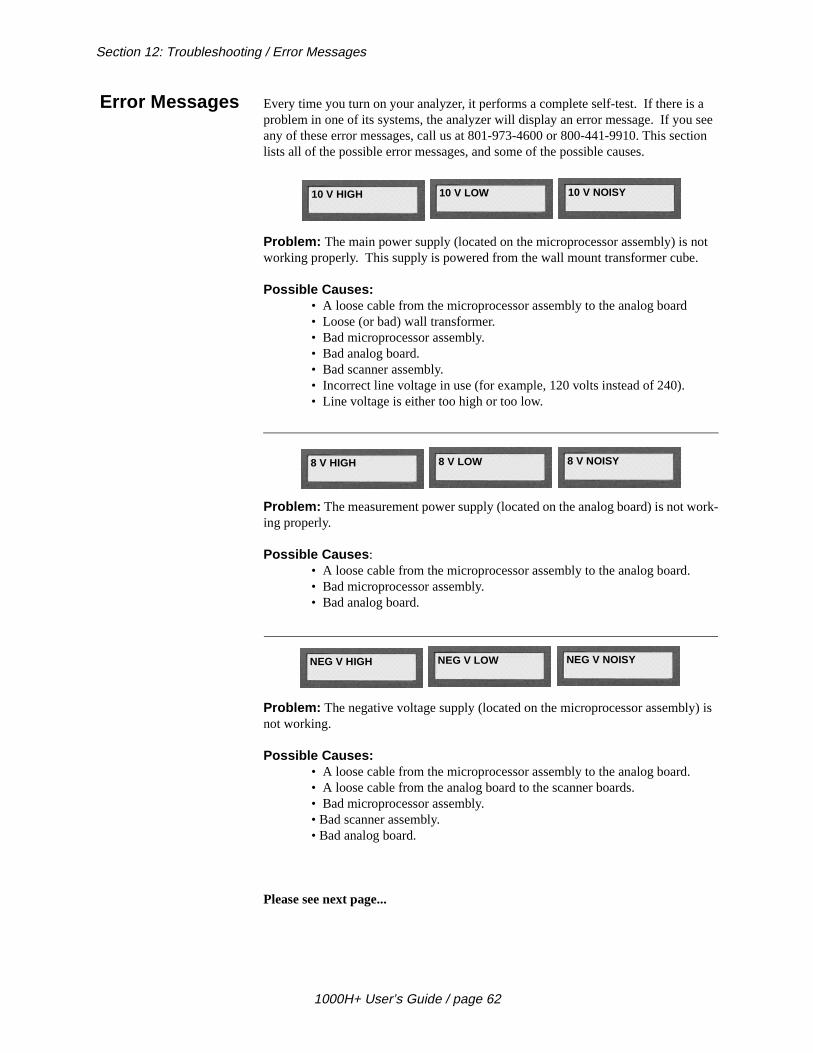
Section 12: Troubleshooting / Error Messages
a see tion
ot .
ork-
) is
Error Messages Every time you turn on your analyzer, it performs a complete self-test. If there isproblem in one of its systems, the analyzer will display an error message. If youany of these error messages, call us at 801-973-4600 or 800-441-9910. This seclists all of the possible error messages, and some of the possible causes.
Problem: The main power supply (located on the microprocessor assembly) is nworking properly. This supply is powered from the wall mount transformer cube
Possible Causes:• A loose cable from the microprocessor assembly to the analog board• Loose (or bad) wall transformer.• Bad microprocessor assembly.• Bad analog board.• Bad scanner assembly.• Incorrect line voltage in use (for example, 120 volts instead of 240).• Line voltage is either too high or too low.
Problem: The measurement power supply (located on the analog board) is not wing properly.
Possible Causes :• A loose cable from the microprocessor assembly to the analog board.• Bad microprocessor assembly.• Bad analog board.
Problem: The negative voltage supply (located on the microprocessor assemblynot working.
Possible Causes: • A loose cable from the microprocessor assembly to the analog board.• A loose cable from the analog board to the scanner boards.• Bad microprocessor assembly.• Bad scanner assembly.• Bad analog board.
Please see next page...
10 V HIGH 10 V LOW 10 V NOISY
8 V HIGH 8 V LOW 8 V NOISY
NEG V HIGH NEG V LOW NEG V NOISY
1000H+ User’s Guide / page 62

Section 12: Troubleshooting / Error Messages
s not
l the
d on
Problem : The current source (located on the analog board) needed for this test iworking.
Possible Causes:• A loose cable from the microprocessor assembly to the analog board.• Bad analog board.
Problem: The measurement system (located on the analog board) cannot controinput signal.
Possible Causes:• A loose cable from the microprocessor assembly to the analog board.• Bad analog board.
Problem : The analyzer was unable to calibrate the measurement system (locatethe analog board).
Possible Causes:• Bad analog board.
Please see next page...
6.2 ma ERROR xxx110 < X 180
OFFSET_C BAD xxx OFFSET C_BAD xxx OFFSETF_HxxxLxxx
OFFSET COARSE OFFSET FINE
66 < X <79 X > 100 ON G8 36 < X , 47
CANT GET TO 25 CANT GO TO 23
LOW CURRENT CAL OFFSET CAL ERROR GAIN xx X vvv
CANT ADJUST CANT ADJUST CALIB. # xxx
CALIB # xxx
ERROR xxx nnn
OFFSET COARSE OFFSET FINE HI<= LO
HI-LO=vv OPB=nnn
1000H+ User’s Guide / page 63
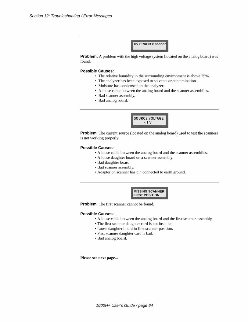
Section 12: Troubleshooting / Error Messages
was
nners
ly.
Problem: A problem with the high voltage system (located on the analog board) found.
Possible Causes: • The relative humidity in the surrounding environment is above 75%.• The analyzer has been exposed to solvents or contamination.• Moisture has condensed on the analyzer.• A loose cable between the analog board and the scanner assemblies.• Bad scanner assembly.• Bad analog board.
Problem : The current source (located on the analog board) used to test the scais not working properly.
Possible Causes : • A loose cable between the analog board and the scanner assemblies.• A loose daughter board on a scanner assembly.• Bad daughter board.• Bad scanner assembly.• Adapter on scanner has pin connected to earth ground.
Problem : The first scanner cannot be found.
Possible Causes : • A loose cable between the analog board and the first scanner assemb• The first scanner daughter card is not installed.• Loose daughter board in first scanner position.• First scanner daughter card is bad.• Bad analog board.
Please see next page...
HV ERROR x nnnnnn
SOURCE VOLTAGE < 3 V
MISSING SCANNERFIRST POSITION
1000H+ User’s Guide / page 64

Section 12: Troubleshooting / General Problems with the Analyzer
is
ted to
nd
eels s
Problem : One of the scanners is missing, or is not connected correctly to the analyzer.
Possible Causes : • Scanner boards not installed properly.• A loose cable from the analog board to the scanner board.• Loose scanner daughter card.• Bad scanner daughter card.• Bad scanner mother board.• Bad cable from analog board to scanner boards.• Bad analog board.
Problem : A test point on a scanner board is not functioning properly. The point located on daughter board ‘v’ on scanner assembly ‘n.’
Possible Causes :• Loose scanner daughter board.• Cable or harness presently connected to analyzer has a point connec
earth ground or to some power source.• A loose cable from the analog board to the scanner assembly.• Bad scanner daughter board.• Bad analog board.
GeneralProblems with
the Analyzer
There are problems you may see with the analyzer that are not detected by the analyzer’s own internal tests. We will talk about those here.
Problem : No display and no sound. The analyzer’s display is totally blank.
Possible Causes : • Bad 10 VAC wall mount transformer.• The intensity control for the display is not adjusted correctly.• Bad microprocessor assembly.
Things to do :
1. Be sure the wall transformer is plugged into a live wall outlet, then feel if it is warm. If the transformer stays cold, it is probably bad. If the outlet is good athe transformer is bad, call Cirris to replace the transformer.
2. If the transformer feels warm, check to see if the microprocessor assembly fwarm. It should warm up within about five minutes after you turn it on. If it istill cold after five minutes, the transformer is bad. Call Cirris to replace it.
SCANNER OUT OFSEQUENCE
BOX n DB V PT nn BOX n DB V PT nn BOX n DB v PT nnSCR ERR SNK ERR CLR ERR
1000H+ User’s Guide / page 65

Section 12: Troubleshooting / General Problems with the Analyzer
-k of
ere
l at the
tem,
place
cro-
f the
3. If the microprocessor assembly feels warm and the display has a blue background, but is otherwise blank, adjust the Display Intensity control at the bacthe analzyer by turning it clockwise. If the display is still blank, call Cirris to replace the microprocessor assembly.
4. If the microprocessor assembly is warm, but the display is totally blank, or this no blue background showing in the display, call Cirris to replace the microprocessor assembly.
Problem : Display shows a darkened row, or gibberish characters.
Possible Causes : • Display Intensity control is not adjusted properly.• Scanner assembly is bad.• Microprocessor assembly is bad.
Things to do :
1. If both rows of the display are dark, try adjusting the Display Intensity controthe back of the analyzer by turning it counterclockwise. If this does not solveproblem, go to step 2.
2. Turn off the analyzer, disconnect the microprocessor from the rest of the systhen turn on the microprocessor. The analyzer should prompt 10 V LO. If it does, the analog board or one of the scanner boards is bad. Call Cirris to reit.
3. If the problem is not solved after the microprocessor is disconnected, the miprocessor assembly is probably bad. Call Cirris to replace it.
Problem : When a cable is disconnected, the display still prompts Please Verify .
Possible Causes:• A cable adapter is bad, or adapting cables are bad.• The scanner assembly is defective.
Things to do :
1. Remove the cable adapters from the analyzer while the analyzer is still on. Ianalyzer still prompts Please Verify , the scanner is probably defective. Call Cirris to replace it.
2. If the analyzer prompts Ready To Test after step one is done, you have unwanted connections in your cable adapters or adapting cables.
Display Intensity control
1000H+ User’s Guide / page 66

Section 12: Troubleshooting / General Problems with the Analyzer
f the is insu-s not ector cog-h as
r con-ana-able.
are into be will
to
c-
.
f
n-
Problem : Connections are not recognized by the analyzer.
Possible Causes : • Bad cable adapters or adapting cables.• Bad scanner assembly.
Things to do:
1. Using the hand-held test probe as a diagnostic tool, use the sharp steel tip oprobe to pierce the insulation on the connecting wire for the connection thatnot being recognized. The pin which is displayed by the analyzer when the lation is pierced is the pin that makes a connection to the wire. The pin that idisplayed is the one that is open. Remove the connector and check the connadapter with the probe to see if the missing pin is recognized there. If it is renized at the test adapter, you may have a worn contact, or contaminants sucsolder flux on the contacts.
2. If you are using an adapting cable, move back to the test point on the adaptenected to the analyzer, and see if the analyzer will recognize it there. If the lyzer recognizes the point, the adapting cable is bad. Rework the adapting c
3. If you are using an AUNV-64, or AHR2-64 adapter, be aware that some pinsused to identify these adapter’s signatures. Because they are incorporated the adapter signature, these connections may cause test points to no longerrecognized. If this is the case, you have miswired your connections, and youhave to rework them.
• To isolate a problem with an AUNV adapter, remove all connectionspin 31, 32, 33, and 34 on a 34-pin connector adapter.
• If you are using an AHR2-64 adapter, make sure there are no connetions to pins 33 and 34.
• If after removing these connections you can now identify these pinswith the probe, you have found the type of miswire described aboveRework your adapting cable.
• It is possible the adapter is bad. Check for worn connectors on the adapter. Also check for continuity of the adapter pin on the bottom othe adapter to the test connector on top. If you find open or worn connections, replace the adapter.
• If you find a bad pin after all these tests, call Cirris to replace the scaner assembly.
Please see next page...
Problem : The analyzer stops operating while it is being used.
1000H+ User’s Guide / page 67

Section 12: Troubleshooting / General Problems with the Analyzer
lug
or
it
bles
to
Possible Causes :• Damage from static electricity.• Bad microprocessor assembly.• Overheating.
Things to do :
1. If static electricity may be a problem, be sure the safety ground on the wall pis connected. Take measures to control static in your work area.
2. If the microprocessor is bad, call Cirris Systems to replace the microprocessassembly.
3. If overheating may be a problem, let the analyzer cool for a few minutes. It comes back on, you may want to direct a cooling fan on the analyzer.
Problem : Speaker problem. There is no sound, but the display works.
Possible Causes : • The Error Tones option is set to OFF.• The speaker inside the analyzer is not plugged in.• The microprocessor assembly is bad.
Things to do :
1. If you hear clicking sounds for cables that test as good, but no sounds for cathat test as bad, the Error Tones option is set to OFF. See page 17 for instructions on how to change the option setting.
2. Connect the speaker wire to the microprocessor assembly.
3. If the speaker wire is connected, but the sounds still do not work, call Cirris replace the microprocessor assembly.
Problem : The sounds the analyzer makes disturb others.
Things to do:
• Set the Error Tones option to OFF or Low.• Place tape over the speaker opening in the metal case to dampen the
sounds.• Disconnect the speaker from the microprocessor.
Please see next page...
1000H+ User’s Guide / page 68
Section 12: Troubleshooting / Problems with Printing
old is
uld be
able
Problem : Analyzer will not learn a cable.
Possible Causes:• The Create Test From option is set to Last Cable.• The Connection Resistance threshold, or Insulation Resistance thresh
not set properly.Things to do :
1. You cannot learn a cable’s wirelist when the Create Test From option is set to
Last Cable. Change the option setting to Sample Cable. See page 17 for instructions on how to do this.
2. If the Insulation Resistance is set to less than the Connection Resistance
(which can take place if the Connection Resistance option is set to AUTO),
then the analyzer will prompt Insulation Resis <AUTO.XXX . The Insulatioin Resistance should be raised to a value above the Connection Resistance set-ting.
Problems withPrinting
Printer failures usually take place because of one of four things:
1. User error.
2. A bad printer.
3. A bad cable.
4. A bad microprocessor assembly.
These guidelies will help you solve printing problems:
Problem : Nothing prints.
Possible Causes :• Printer is not on-line (selected).• Cable between analyzer and printer is not connected properly.• The printer has a serial instead of a parallel interface.• A bad cable.• A bad printer.• A bad microprocessor assembly.
Things to do :1. Make sure the printer is turned on, on-line (selected), and not out of paper.
2. Check the cable connections at the analyzer and the printer. The cable shofirmly connected to the back of the analyzer where it is marked Printer-Parallel Interface. Check the connection at the printer end too.
3. Your printer must have a parallel cable interface. Do not use a printer with an RS-232 serial interface. You will damage the analyzer.
4. The cable running from the analyzer to the printer may be bad. Try another cto see if it works.
1000H+ User’s Guide / page 69
Section 12: Troubleshooting / Problems with Printing
er it is
the
s. able
bly
2
your a with
han er
nge olves
5. The printer may be bad. Try using another printer, or test your original printand cable with a standard computer. If the printer does not work with the PC,probably bad.
6. If the cable and printer work with a PC, the microprocessor assembly insideanalyzer is probably bad. Call Cirris to replace it.
Problem : Characters missing in printout.
Possible Causes :• Bad printer cable.• Printer cable is too long.• Printer is incompatible with the analyzer.• Microprocessor assembly inside the analyzer is bad.
Things to do :
1. Verify that the printer cable is correctly built. Check for shorts in pin 11.
2. If the printer cable is more than 10 feet long, you may have printing problemThe electrical signals from the printer become too weak to work well as the cgets longer. Use a shorter printer cable.
3. Try using the printer cable with a PC. If it works, the printer probably is not compatible with the analyzer.
4. If the cable and printer work with a PC, the analyzer’s microprocessor assemis probably bad. Call Cirris to replace it.
Problem : Wrong characters in printout.
Possible Causes :• Bad printer cable.• Bad printer.• Printer cable too long.• Microprocessor assembly inside the analyzer is bad.
Things to do :
1. The printer cable may be bad. Check for shorts, opens, or miswires on pinsthrough 9. Either fix the cable, or replace it with a good cable.
2. The printer may be bad. Try using another printer with the analyzer, or test original printer cable and printer with a PC. If the printer does not work withPC, the printer is bad. Replace the printer. If the printer and cable do work a PC, the analyzer’s microprocessor assembly is probably bad.
3. The printer cable may be too long. Your printer cable should not be longer t10 feet. The printer signals get too weak to work properly if the cable is longthan 10 feet.
4. If you have another Cirris 1000H+ analyzer available, it is possible to exchamicroprocessor assemblies. If using a different microprocessor assembly sthe problem, the original microprocessor is bad. Call Cirris to replace it.
1000H+ User’s Guide / page 70

ed will
no-no-
ve
allel
Section 13: Specifications
Test Point Capacity 128 points expandable to 256, 384, or 512 points.
Test Levels 5 VDC @ 6mA max. current.
Connection resistancesentisivity
0.1 to 100Kohms ± 4% ± 0.1 ohm, also 500K, 1M, and 5Mohms ± 20%.
Insulation resistancesensitivity
5M, 10M, 20M, 50M, 100M, 200MΩ ± 10%, and 500 Mohms ±20%.
Typical test rate Tests 512 points in less than 3 seconds, 128 points in less than 0.3 seconds (spechange with parameter selection, OR 128 points per second (typical).
Maximum points pernet
50 points (100 points with auxiliary power supply).
Maximum capacitanceper net
@50V 0.1 microfarad, 100 V 0.1 microfarad, 200 V 0.03 microfarad, 300 V 15 nafarad, 400 V 7 nanofarad, 630 V 3 nanofarad, 800 V 1.5 nanofarad, 1000 V 1 nafarad.
Humidity Will test without error in environments with zero to 75% relative humidity. Relatihumidity above 75% will affect performance.
HV energy limit Current limited to 6ma max. for ten ms duration.
Printer output Standard Epson/Centronics-type parallel interface. Pinout matches IBM PC parport.
Probe For test point identification.
Memory Nonvolatile storage for up to 50 wirelists. Lithium battery backup.
Power 105-135 VAC, 60Hz 16 Watts (210-260 VAC 50Hz optional).
Size Main unit: 13”w X 6.5” d X 5” h./33 X 16.5 X 13 cm.Expansion box: 6” w X 6.5” d X 5” high/15 x 16.5 x 13 cm.
Weight Main unit: 9 lbs. (4 kgs.)Expansion box: 5 lbs. (2.3 kgs.)
Display 2-line x 16-character LCD
Warranty 1 year parts and labor. Replacement modules available next working day.
1000H+ User’s Guide / page 71

Section 13: Specifications / Warranty
1000H+ User’s Guide / page 72
fects ry to fect
ir or r-
unit be
r-s war-
er t of ris
ion
Section 14: Statement of Warranty
Cirris Systems Corporation warrants the 1000H+ Cable Analyzer to be free of dein materials and workmanship for a period of one (1) year from the date of deliveyou, as evidenced by receipt of your warranty registration form. In the event a dedevelops due to normal use during the warranty period, Cirris Systems will repareplace the analyzer with a new or reconditioned unit of equal value. For this waranty to be valid you must complete and return the warranty registration card.
In the event of replacement with a new or reconditioned model, the replacementwill continue the warranty period of the original analyzer. Replacement units will returned by the same method shipped; generally within one (1) working day.
If analyzer failure results from accident, abuse, or misapplication, Cirris SystemsCorporation shall have no responsibility to replace the analyzer or refund the puchase price. Defects arising from such causes will be considered a breach of thiranty. Cirris Systems Corporation is not responsible for special, incidental, or consequential damages resulting from any breach of warranty, or under any othlegal theory, including lost profits, downtime, goodwill, damage to or replacemenequipment and property, and any costs of recovering materials used with the Cir1000H+ Analyzer.
ANY IMPLIED WARRANTIES ARISING OUT OF SALES OF THE 1000H+ ANALYZER, INCLUDING BUT NOT LIMITED TO IMPLIED WARRANTIES OF MERCHANTABILITY AND FITNESS FOR A PARTICULAR PURPOSE ARE LIMITED IN DURATION TO THE ABOVE STATED ONE (1) YEAR PERIOD. Cirris Systems SHALL NOT BE LIABLE FOR INCIDENTAL OR CONSEQUENTIAL DAMAGE, EXPENSES, OR ECONOMIC LOSS.
Some states do not allow limitations on length, or implied warranty, or the exclusor limitation of incidental or consequential damages, so the above limitations or exclusions may not apply to you.
This warranty gives you specific legal rights and you may also have other rights which vary from state to state.
Cirris Systems CorporationSalt Lake City, Utah.
PLEASE RECORD PURCHASE DATE AND SERIAL NUMBER BELOW.
DATE:________________________________SERIAL NUMBER: ______________________
1000H+ User’s Guide / page 73

Section 14: Statement of Warranty
1000H+ User’s Guide / page 74
tions.
llow s sig- the
are ter.
on-J1, J2,
cable
a
lly in a
s a
t
Section 15: Glossary
cable signature A six-character alphanumeric code that changes with any change in interconnecValid characters include the numbers 0 through 9, and the letters A through F.
connection resistance Option setting that allows you to select the maximum allowable resistance that a “good” connection can have.
connector adapter Connector adapters are adapters mounted on small printed circuit boards, that ayou to connect the cables you want to test to the 1000H+. There are three type(single-high, double-high, quad-high). Each adapter has its own unique adapternature. Adapters are usually kept organized in a 3 x 5-inch card file. You identifyadapter by its signature, either on the cardboard sleeve in which the adapter is shipped, or by the signature printed on the label on the adapter itself. Adapters identified by the connector they mate to, not the connector mounted on the adap
connector adapterposition
The location either on the analyzer’s main unit, or on an expansion box where cnector adapters are mounted. The main unit has four such positions, marked as J3, J4. Each expansion box also has four connector adapter positions.
control The regulation of manufacturing or assembly processes; particularly the use of a signature for verifying the test setup against the documentation.
cable documentation The written definition of how a cable should be constructed. Usually consists ofwirelist, and a complete set of notes on what connectors, materials, and special techniques should be used to build the cable successfully.
hipot Hipot stands for HIgh POTential. Hipot tests are done to verify that the resistance between pins that are not supposed to be connected is sufficiently high. Generaused to check the effectiveness of insulation and/or spacing between conductorscable.
hipot duration The length of time for which hipot voltage is applied to each net during hipot testing.
Insulation Resistance Option setting that allows you to select the minimum allowable resistance between points that should not be connected.
insulation short An insulation short occurs when the resistance of a connection is higher than the Connection Resistance setting, and lower than the Insulation Resistance setting. In other words, the connection has a resistance too high for the analyzer to see it a“good” connection, and too low for the analyzer to see it as effective insulation.
interconnection A situation where continuity exists between two connector pins. Continuity moscommonly exists here because a wire connects the two pins.
1000H+ User’s Guide / page 75
Section 15: Glossary / intermittent
fer h le
are le you atch
y the mple
nent” the nes
actu-
igns zer’s
tor
git ts s of
ed
intermittent The 1000H+ detects an intermittent fault when a cable is seen to develop shorts, opens, or excessive resistance after it has already tested as good.
known-good cable A known-good cable is a cable that you know is built correctly. We most often reto such a cable as a Sample Cable. You can program the 1000H+ to test cables whicare supposed to be like the Sample Cable by letting the analyzer learn the SampCable. When the list of interconnections and the other properties of a cable youtesting are not the same as those of the Sample Cable, the signature of the cabare testing will not match the signature of the Sample Cable. This signature mismwill be reported as a “bad” cable.
last test setup The last wirelist (including all test parameters and adapter information) learned banalyzer. This can be loaded into the analyzer for testing either by learning a SaCable, or by retrieving the wirelist information for a cable from the analyzer’s memory.
memory location The 1000H+ has one “last learned” memory location, and as many as 50 “permamemory locations. The number of available locations depends upon the size of wirelists being stored. Large wirelists take up more memory space than small odo. You can load cable information into the analyzer for testing by retrieving theinformation from one of these memory locations. It is also possible to delete old wirelist information from specific memory locations to free up memory for storingnew cable information.
microprocessor The electronic assembly which includes the LCD display. As you look at the analyzer from above, the microprocessor assembly is located to the left.
miswire A type of interconnection error where a one pin is incorrectly connected to another pin. For example, if a connection is supposed to exist between pins 5 and 6, butally exists between pins 5 and 7, the error will be reported as a miswire.
net Any group of pins which are connected together. The analyzer automatically assa number to each group of interconnected pins (called nets). This number appears onthe left-hand side of printed documentation, and in the left-hand side of the analyLCD display.
open A kind of interconnection error where there is no continuity between two connecpins which are supposed to be connected. A connection which the cable’s masterdocumentation says should exist, does not in fact exist in the cable.
parameter signature When it displays signatures, the analyzer displays a six-digit alphanumeric cable signature followed by a hyphen. After the hyphen, the analyzer displays a five-dialphanumeric known as the parameter signature. The parameter signature representhe various test options you have selected for your test setup. Two different kindcables will always have different cable signatures; but they may have the same parameter signature if the option settings for both types were identical.
pin An electrical contact point within a connector. In this manual, the word “pin” is usin place of terms such as “point,” “contact,” “socket,” “termination,” etc.
1000H+ User’s Guide / page 76
Section 15: Glossary / Sample Cable
ild
ight-you nti-
are he
Sample Cable A Sample Cable is a cable you know is built correctly according to your master bulist.
scanner assembly If you look at the analyzer from above, the scanner assembly is located on the rhand side of the unit’s top. This assembly contains the “J” positions onto which install your connector adapters. It also contains the electronics which control conuity testing between all connector pins in all possible combinations.
setup The steps involved in preparing the analyzer to test cables.
short A kind of interconnection error where there is continuity between two points thatnot supposed to be connected. A connection is present that does not appear in tmaster cable documentation.
1000H+ User’s Guide / page 77

Section 15: Glossary / short
1000H+ User’s Guide / page 78

s you
at
re-l
Section 16: Blank Forms to Photocopy
What are these for? We have designed three forms that we believe will help you document the cabletest. They are:
• Master Parts List: This form will help you keep track of cables by their part numbers and cable signatures.
• Directory of Wirelists Stored in Analyzer’s Memory: This form allows you to easily write down which cable’s information is stored ineach of the analyzer’s permanent memory locations. Remember ththere are a maximum of 50 memory positions available, and that thenumber of positions actually available depends on the size of the wilist you are storing. Large wirelists take up more memory than smalones do.
• Cable Documentation Form: This form lets you keep track of signatures, option settings, and net lists for each cable you test.
PHOTOCOPY THESE! You should photocopy these forms instead of writing directly on them. That wayyou’ll have a fresh supply of blank forms whenever you need them.
1000H+ User’s Guide / page 79

Section 16: Blank Forms to Photocopy
1000H+ User’s Guide / page 80
Master Parts ListCable Part Number Description Signature
Copyright 1999 by Cirris Systems Corporation


Directory of Wirelists Stored in Analyzer’s Memory
123456789
1011121314151617181920212223242526272829303132333435353738394041424344454647484950
MemoryLocation Cable Description Signature
Copyright 1999 by Cirris Systems Corporation

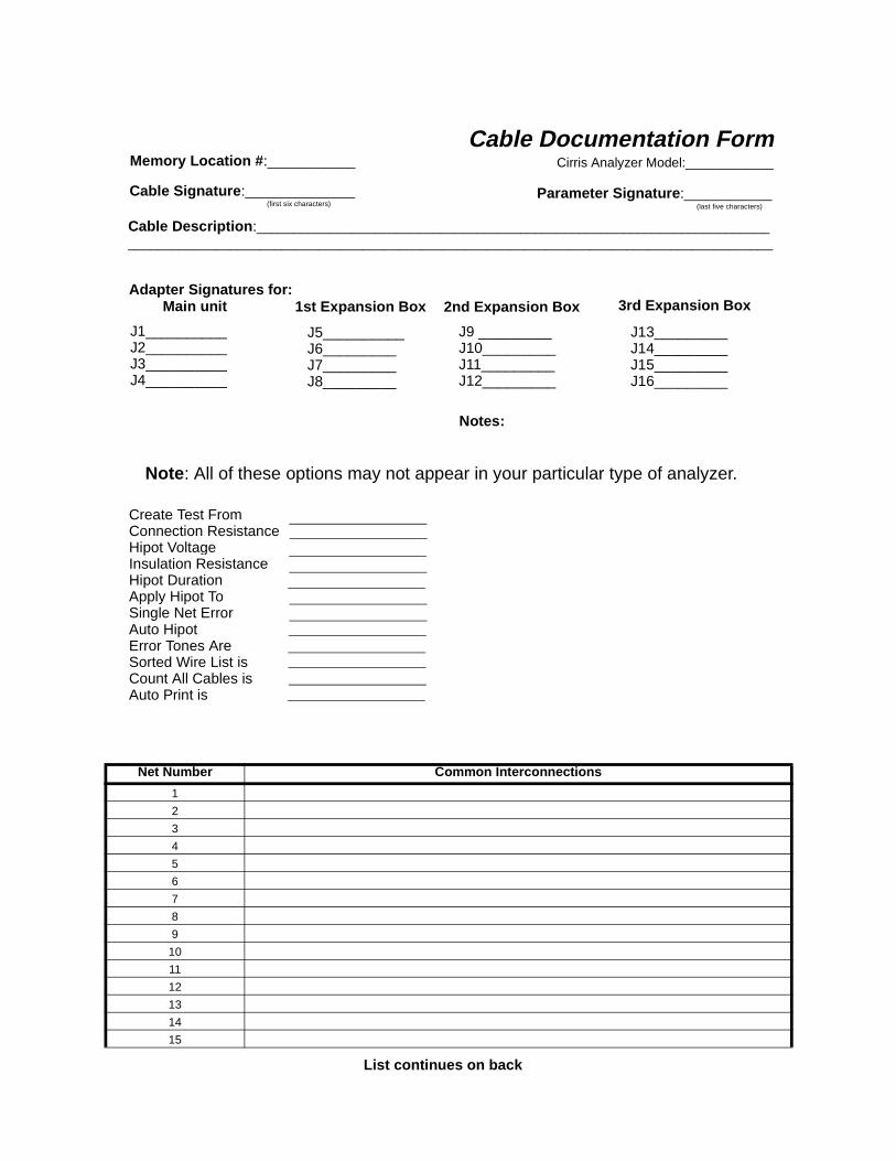
Net Number Common Interconnections
1
2
3
4
5
6
7
8
9
10
11
12
13
14
15
Cable Documentation FormCirris Analyzer Model:____________
Parameter Signature :____________(last five characters)
Memory Location # :____________
Cable Signature :_______________(first six characters)
Cable Description :______________________________________________________________________________________________________________________________________________________________
Adapter Signatures for:Main unit
J1__________J2__________J3__________J4__________
1st Expansion Box 2nd Expansion Box 3rd Expansion Box
J5__________J6_________J7_________J8_________
J9 _________J10_________J11_________J12_________
J13_________J14_________J15_________J16_________
Notes:
Create Test FromConnection ResistanceHipot VoltageInsulation ResistanceHipot DurationApply Hipot ToSingle Net ErrorAuto Hipot Error Tones AreSorted Wire List isCount All Cables isAuto Print is
Note : All of these options may not appear in your particular type of analyzer.
List continues on back
Use additional page if necessary
16
17
18
19
20
21
22
23
24
25
26
27
28
29
30
31
32
33
34
35
36
37
38
39
40
41
42
43
44
45
46
47
48
49
50
51
52
53
54
55
56
57
58
59
60
61
62
63
64
65
Net Number Common Interconnections
Copyright 1999 by Cirris Systems Corporation

nce of
irris
t ts
Appendix 1: Four-Wire Testing on the 1000H+
Capability andTolerances
The 1000H+ can measure resistances from 0.010 ohms to 10 ohms with a tolera4% or 5 milliohms (whichever is greater). The 1000H+ can make relative measurements down to 1 milliohms (0.001 ohms).
Adapters To do four-wire testing on your 1000H+, you’ll need the appropriate adapters (Cadapter signature FBEA7D) as shown here.
Installing Four-Wire Adapters
These are continuous-count adapters. You must install them in the analyzer starting ascanner position J1, so that all empty scanner positions are to the right of the sloalready in use.
1000H+ User’s Guide / page 87
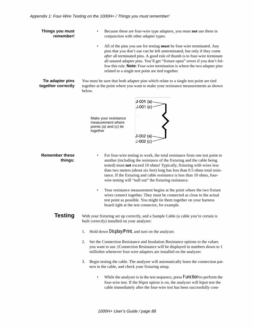
Appendix 1: Four-Wire Testing on the 1000H+ / Things you must remember!
e te l-s
d shown
to
sis-r-
ure ual
s
ues to 1
pat-
-
Things you mustremember!
• Because these are four-wire type adapters, you must not use them in conjunction with other adapter types.
• All of the pins you use for testing must be four-wire terminated. Any pins that you don’t use can be left unterminated, but only if they comafter all terminated pins. A good rule of thumb is to four-wire terminaall unused adapter pins. You’ll get “fixture open” errors if you don’t folow this rule. Note : Four-wire termination is where the two adapter pinrelated to a single test point are tied together.
Tie adapter pinstogether correctly
You must be sure that both adapter pins which relate to a single test point are tietogether at the point where you want to make your resistance measurements as below.
Remember thesethings:
• For four-wire testing to work, the total resistance from one test pointanother (including the resistance of the fixturing and the cable beingtested) must not exceed 10 ohms! Typically, fixturing with wires less than two meters (about six feet) long has less than 0.5 ohms total retance. If the fixturing and cable resistance is less than 10 ohms, fouwire testing will “null out” the fixturing resistance.
• Your resistance measurement begins at the point where the two fixtwires connect together. They must be connected as close to the acttest point as possible. You might tie them together on your harness board right at the test connector, for example.
Testing With your fixturing set up correctly, and a Sample Cable (a cable you’re certain ibuilt correctly) installed on your analyzer:
1. Hold down Display/Print, and turn on the analyzer.
2. Set the Connection Resistance and Insulation Resistance options to the valyou want to use. (Connection Resistance will be displayed in numbers downmilliohm whenever four-wire adapters are installed on the analyzer.
3. Begin testing the cable. The analyzer will automatically learn the connectiontern in the cable, and check your fixturing setup.
• While the analyzer is in the test sequence, press Function to perform the four-wire test. If the Hipot option is on, the analyzer will hipot test thecable immediately after the four-wire test has been successfully com
Make your resistancemeasurement wherepoints (a) and (c) tietogether
1000H+ User’s Guide / page 88

Appendix 1: Four-Wire Testing on the 1000H+ / The value of four-wire testing
i-
u- to
ns ts,
d
is-g
-
ge of
the
to
g
e
the points rom mea-
er is it is if
ality
nnec-ce on
build cts
pleted. If the Auto Hipot function is turned on, the cable will automatcally be four-wire tested, then hipot tested.
• Before and after a four-wire test, the cable is tested for proper continity. A continuous low-current connection resistance test is performeda level 100 milliohms above the four-wire connection threshold.
• The analyzer checks your fixturing continuously. Using the connectiotest, it constantly checks for the presence of intermittent short circuiand fixture wires that should be connected together.
• Immediately prior to performing each high-current measurement, theresistance is measured using low current. High current is then appliebased on that two-wire resistance measurement (if the two-wire restance is less than 10 ohms). This prevents the analyzer from applyinhigh current that could damage a contact while a cable is being connected.
The value offour-wire
testing
Simply stated, a four-wire test is a test for wires and contact points. The advantafour-wire testing over ordinary two-wire resistance testing is that four-wire testing“nulls out” the resistance of the test fixturing. Only the resistance of the wire andcontact itself is measured.
How four-wire testingworks
In four-wire testing, a known amount of electrical current flows from point J-001 point J-002. To “null out” the resistance of the test fixturing, two wires are connected to each test point. One of these wires provides a known amount of current flowininto (“sourced into”) point J-001.
A second wire is connected to point J-002. It provides a return (“sink”) path for thcurrent flowing into J-001.
The other two wires (one to point J-001, the other to point J-002) work much likeprobes on a voltmeter to measure voltage. The voltage drop across the two test (J-001 and J-002) is measured. The resistance is then automatically calculated fthe voltage drop reading using Ohm’s Law. The result is the four-wire resistance surement.
Limitations of four-wire testing
The accuracy of the analyzer limits the effective range of four-wire testing. A testless accurate when it tests cables which have over ten ohms of resistance, thanthe fixturing resistance is “nulled out” using the four-wire testing technique.
Four-wire testing may satisfy a testing specification. It offers no advantage for quassurance testing of cables which have more than 10 ohms of resistance.
Four-wire testing does not eliminate problems caused by the resistance of test cotors. Connectors wear a bit with each insertion cycle. This wear creates resistanthe test connector, which four-wire testing does not “null out.” To be certain that your tests remain accurate, you must maintain the analyzer’s connectors carefully, or special four-wire test connectors which use spring-loaded contacts. These contawear less with each insertion cycle than traditional connectors do.
1000H+ User’s Guide / page 89
Appendix 1: Four-Wire Testing on the 1000H+ / Using Cirris Test Language (CTL) Commands
’ll
e,
ndi-
sure-
r fix-
con- to a
Using CirrisTest Language
(CTL)Commands
You can use Cirris Test Language (CTL) while you’re doing four-wire testing. Wediscuss some of the details here.
RESIS() RESIS() will perform a four-wire test (if necessary) to establish a resistance valuand will check the validity of only the points being accessed.
CR_TEST() CR_TEST() may also perform a four-wire test if the low-current connection test icates that this has to be done to determine an accurate resistance.
CR4TEST CR4TEST performs a continuity test followed by a four-wire test.
Specifications These are the specifications for the 1000H+ as they relate to four-wire testing:
Range 0.010 ohm to 10 ohms starting in 1 milliohm increments. Can make relative meaments down to 1 milliohm (0.001 ohms).
Accuracy 4% tolerance or 5 milliohms, whichever is greater.
Current used 1.00 amp for fixture and connection resistance less than 1.2 ohms, 0.250 amp foture and connection resistance less than 10 ohms.
Low-current test Less than 10 milliamps is used to perform a continuous test whenever a cable isnected to the 1000H+. The cable is tested using low-current four-wire techniquesthreshold of 100 milliohms above the high-current four-wire threshold to look forintermittent short circuits.
1000H+ User’s Guide / page 90
ce
Index
AAdapter signature
see Connector adapter signature 39Adapters
how they are placed on analyzer 41how they are placed on expansion boxes 41how they are supported 40how to install 9order of positions 42sample wirelist showing them 42Types
double-high 40quad-high 41single-high 40
Adding a printer 15Apply Hipot To option
what it does 20Auto Hipot option
what it does 21AUTO mode 19Auto Print option
what it does 21
CCable documentation
how to interpret 38Sample documentation forms 79what it is 37why prepare it? 37
Cable signaturewhat it is 39
CALC mode 19, 44Changing the EPROM 13Complex assembly
how to interpret documentation 48how to learn 46how to test 49limitations when testing 50
Complex testFirst pass
check components test 49hipot test 49insulation test 49
wires test 49Complex tests
how to determine Connection Resistansetting for 44
Connection ResistanceAUTO mode 19CALC mode 19
Connector adapter signaturewhat it is 39
Count All Cables optionwhat it does 21
Create Test From optionwhat it does 19
DDeleting a cable from memory 33Dielectric Fail
what it means 29Documentation
changing the company name 16from complex assembly
interpreting 48
EEPROM
how to change it 13Error List
Print or transcribe 30Error Message
Dielectric Fail 29what it means 29
Errors Detected 28what it means 28
Failed Hipot Test 29what it means 29
Goodwhat it means 27
Has Leakage 29what it means 29
Intermittent 29what it means 29
Open Detected 28what it means 28
Over Current 29what it means 29
print or transcribe an error list 30Short Detected 28
1000H+ User’s Guide / page 91
what it means 28While learning a Sample Cable
what to do 25Error Tones option
what it does 21Errors Detected
what it means 28Expansion box
how to install 10
FFailed Hipot Test
what it means 29Forms
blank, for photocopying 79Four-wire testing
Adapters 87installing 87
Capability and tolerances 87Limitations 89Specifications 90Testing 87Using CTL commands 90value 89
Four-wire testing on the 1000H+ 87
GGetting started 7Glossary 75Guided assembly
building cables pin-to-pin 59building cables with one terminated end 60
HHas Leakage
what it means 29Hipot Test
Passed 30Hipot test
"Has Leakage" error 52dielectric failure error 52hipot voltage and capacitance problems 53interpreting results 28must pass continuity test first 51overcurrent error 51purpose of 51tips on setting voltage 52
Hipot Voltage optionwhat it does 19
How to install an expansion box 10How to install connector adapters 9
IInsulation Resistance
tips on setting 53Insulation Resistance option
what it does 20Intermittent
what it means 29
LLast Learned
what it is 23Learn
Sample Cable 23
MMemory
Available in the 1000H+ 23How to delete a cable 33How to print a directory 35How to retrieve a cable 31Last Learned 23Why delete a cable? 33Why retrieve a cable? 31
OOpen Detected
what it means 28Option settings
Apply Hipot To 20Auto Print
what it does 21Connection Resistance
Auto mode 19CALC mode 19
Count All Cableswhat it does 21
Create Test FromComplex Assembly 19Last Test Setup 19Sample Cable 19
Error Tones optionwhat it does 21
hipot duration
1000H+ User’s Guide / page 92

e
s-
what it does 20hipot voltage 19how to check 17Insulation Resistance
hipot voltage vs. insulation resistancesettings 20what it does 20
setting to learn a complex assembly 46Single Net Error
what it does 21Sorted Wire List
what it does 21what they mean 19
Optionswhen they are saved 18
Over Currentwhat it means 29
PPacking List
what your order should contain 7Parameter signature
what it is 39Passed Hipot Test 30
what it means 30pecifies 19Printer
How do I know if I have a parallel printer?15
how to add 15how to use with more than one analyzer 16
Printinga directory of Sample Cables in memory 35
Probedisplaying multiple interconnected pins 56how to install 55identifying an open circuit 56identifying test points 55
RRetrieving a cable from memory 31Rework
correcting opens 59instructions 56removing shorts within a net 56, 57
SSample Cable
how to delete from memory 33how to learn 23how to store in memory 24learning
what to do if you see an error messag25
what it is 77Short Detected
what it means 28Signatures
how they work 39Types
cable signature 39connector adapter signature 40parameter signature 39
Single Net Error optionwhat it does 21
Sorted Wire List optionwhat it does 21
Specifications 71
TTest procedures
Complex testshow to determine Connection Resitance setting for 44
Typescomplex tests 44simple tests 43
These are the connector adapter signatures38Three general adapter types 40to 27To print out a directory 35To retrieve a learned cable’s 31To store the cable 24Troubleshooting 61
Error Messagesgeneral problems with analyzer 65problems with printing 69prompted in display 62
Types of adapters 40
1000H+ User’s Guide / page 93

WWarranty 73What to do if you go past the value you want18
1000H+ User’s Guide / page 94


![ECLIPSE - FOLIO · .ECLIPSE 100 [mm] OPTION .A cable ≤ 3000 mm 23 100 d 23 100 d [mm] OPTION .B d w cable ≤ 3000 mm GENERAL INFO Suspended LED panel Aluminum - Methacrylate (PMMA)](https://img.dokumen.tips/doc/110x75/5eb78d69fa986a6f0b53d6f5/eclipse-folio-eclipse-100-mm-option-a-cable-a-3000-mm-23-100-d-23-100-d.jpg)